Synthesis, Characterization and Catalytic Investigation of Metal-Organic Frameworks constructed from Salen Type Metalloligands Agnes Eva Þórarinsdóttir Faculty of Physical Sciences University of Iceland 2015
Transcript
Synthesis, Characterization and Catalytic
Investigation of Metal-Organic Frameworks
constructed from Salen Type Metalloligands
Agnes Eva Þórarinsdóttir
Faculty of Physical Sciences
University of Iceland
2015
Synthesis, Characterization and Catalytic
Investigation of Metal-Organic Frameworks
constructed from Salen Type Metalloligands
Agnes Eva Þórarinsdóttir
15 ECTS thesis submitted in partial fulfillment of a
Baccalaureus Scientiarum degree in Chemistry
Advisor
Dr. Krishna Kumar Damodaran
Faculty of Physical Sciences
School of Engineering and Natural Sciences
University of Iceland
Reykjavík, May 2015
Synthesis, Characterization and Catalytic Investigation of Metal-Organic Frameworks
constructed from Salen Type Metalloligands
Efnasmíð, greining og könnun á hvatavirkni málmlífrænna grinda smíðuðum úr salen-
afleiddum málmtenglum
15 ECTS thesis submitted in partial fulfillment of a B.Sc. degree in Chemistry
Table 4.2 ESI-MS analysis of 6aI-6aIII and 7aI-7aIII ................................................... 34
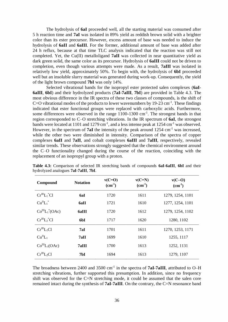
Table 4.3 Comparison of selected IR bands of 6aI-6aIII, 6bI and 7aI-7aIII, 7bI ........... 36
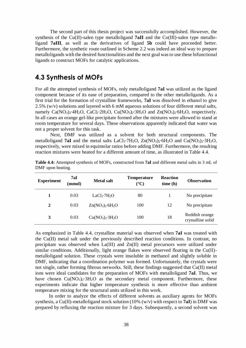
Table 4.4 Attempted synthesis of MOFs in DMF; different metal salts ........................... 38
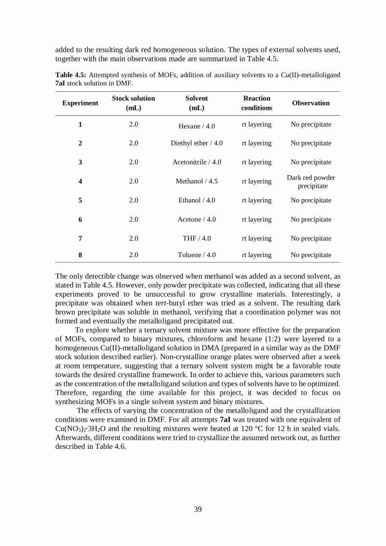
Table 4.5 Attempted synthesis of MOFs in DMF; effects of auxiliary solvents ............... 39
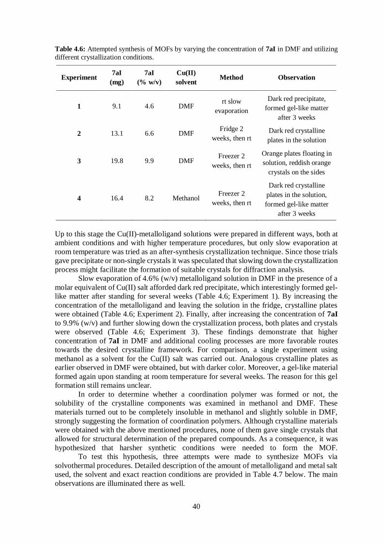
Table 4.6 Attempted synthesis of MOFs in DMF; different crystallization conditions ..... 40
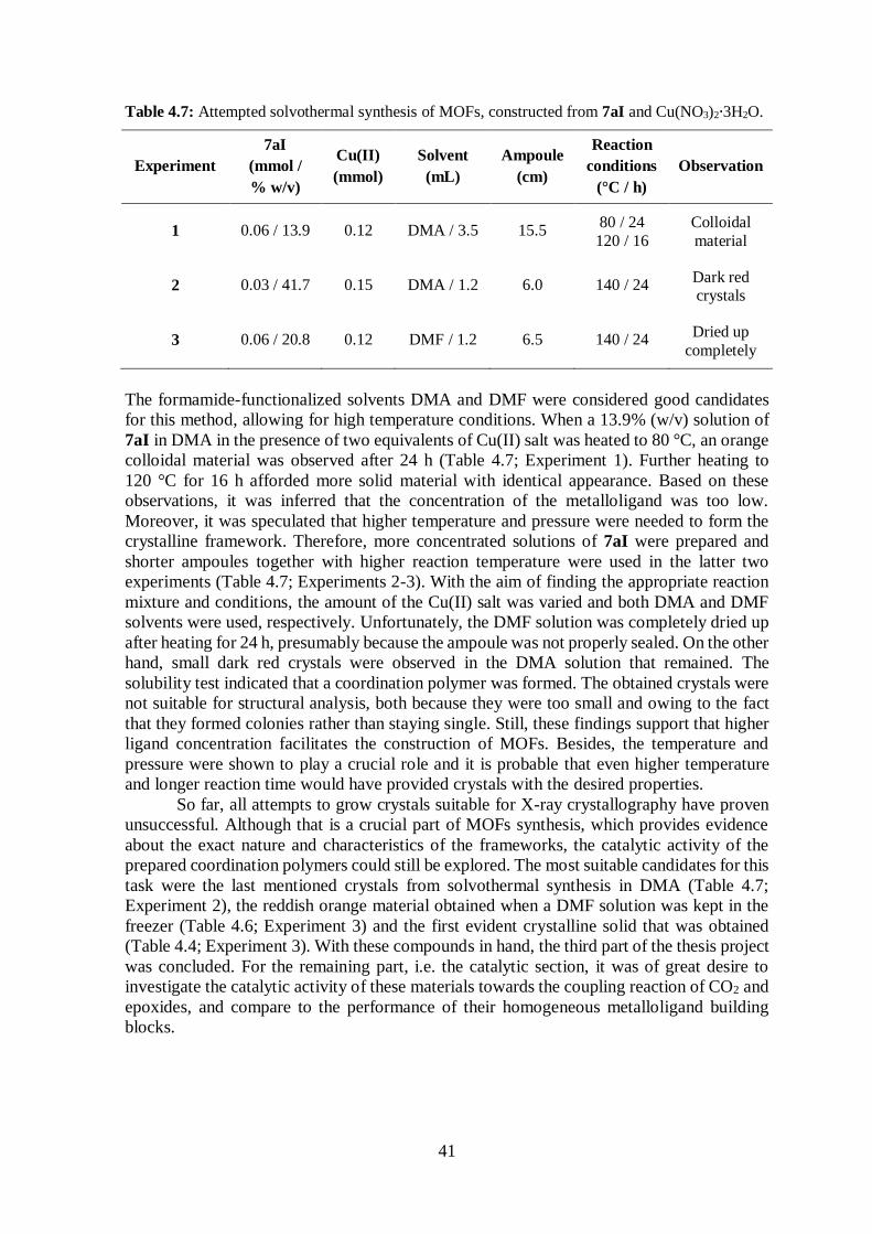
Table 4.7 Attempted solvothermal synthesis of MOFs .................................................... 41
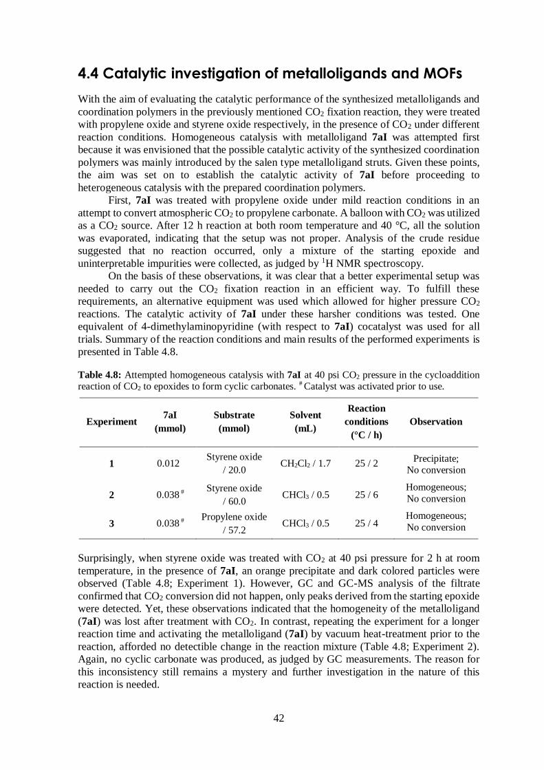
Table 4.8 Attempted high pressure CO2 homogeneous catalysis with 7aI ....................... 42
xii
List of Abbreviations
MOF Metal-organic framework
PCP Porous coordination polymer
SBU Secondary building unit
2D Two-dimensional
3D Three-dimensional
4,4’-bpy 4,4’-bipyridine tBu tert-butyl
OAc- acetate
ee enantiomeric excess
SN2 Substitution nucleophilic bimolecular
DMA N,N-Dimethylacetamide
DMF N,N-Dimethylformamide
DMSO Dimethyl sulfoxide
EtOH Ethanol
MeOH Methanol
THF Tetrahydrofuran
GC Gas chromatography
TLC Thin layer chromatography
ESI-MS Electrospray ionization mass spectrometry
HRMS High resolution mass spectrometry
MS Mass spectrometry
m/z mass-to-charge ratio
UV Ultraviolet
IR Infrared
s strong
m medium
w weak
NMR Nuclear magnetic resonance
δ chemical shift
s singlet
d doublet
dd doublet of doublets
t triplet
m multiplet
ppm parts per million
Hz hertz
psi pounds per square inch
rt room temperature
calcd calculated
xiii
Acknowledgements
First and foremost I would like to express my sincere gratitude to my advisor, Dr. Krishna
Kumar Damodaran for his guidance and advice during my work on this project. It has been
a great and informative experience working with him.
I would like to give my special thanks to my colleagues at the lab Dipankar Ghosh, Jóhann
Daði Magnússon and Zala Krzisnik for their assistance, helpful discussions and great
company throughout this fantastic spring semester.
Additionally, I would especially like to thank the following people at the University of
Iceland:
Dr. Sigríður Jónsdóttir for NMR, ESI-MS, GC and GC-MS measurements.
Prof. Ingvar H. Árnason for his assistance with sealing ampoules and providing a
CO2 cylinder for catalytic experiments.
Svana H. Stefánsdóttir for providing solvents and chemicals.
Sverrir Guðmundsson for providing glassware and other equipment for the lab.
And all four of them for generally being very kind and helpful.
Furthermore, I would like to thank all the fabulous students, faculty and staff at the Science
Institute for all the help through my studies and the work on this thesis project. They all
contribute to the inspiring environment to study chemistry at the University of Iceland.
Anette Kristin Jacobsen and Kolbrún Helga Hansen are acknowledged for the support on
reviewing this thesis.
At last but certainly not the least, I would like to thank my family and my good friends for
their endless patience and support throughout my studies.
1
1 Introduction
1.1 Catalysis There is no doubt that catalysis is indispensable to mankind. Catalysis plays a key function
in all biological reactions and is utilized in over 80% of all chemical industrial processes,
which fulfills the societal needs, including food, clothes and fuel production. A catalyst is a
chemical species that accelerates a chemical reaction, by offering an alternative and
energetically more favorable pathway to the non-catalyzed reaction and is returned to its
original state at the end of the reaction. Thereby, the use of catalysts enables processes to be
carried out under more feasible reaction conditions, such as temperature and pressure that
are attainable in industry. Yet, a catalyst only changes the kinetics of the reaction but not the
thermodynamics, i.e. the overall change in free energy for a catalytic reaction equals that of
the uncatalyzed reaction, this is because the catalyst accelerates forward and reverse reaction
to the same extent. A characteristic of all good catalysts is the balance between bonding to
reactants and separation from products. If the bonding is too weak the reactants cannot be
readily activated, and if the bonding is too strong stable intermediates do form, both of which
make the conversion of reactants to products unlikely. Three key parameters are often used
to evaluate catalyst performance, i.e. activity, selectivity and stability. To date, various
catalytic systems exist, which can be classified into three categories depending on the nature
of the catalysis: (1) enzymatic, (2) homogeneous and (3) heterogeneous catalysis.1-4
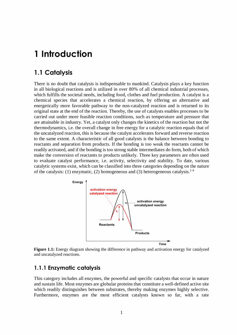
Figure 1.1: Energy diagram showing the difference in pathway and activation energy for catalyzed
and uncatalyzed reactions.
1.1.1 Enzymatic catalysis
This category includes all enzymes, the powerful and specific catalysts that occur in nature
and sustain life. Most enzymes are globular proteins that constitute a well-defined active site
which readily distinguishes between substrates, thereby making enzymes highly selective.
Furthermore, enzymes are the most efficient catalysts known so far, with a rate
2
enhancements in the range of five to seventeen orders of magnitude (105-1017). As a
consequence, it is reasonable that scientists frequently bear the structures of enzyme active
sites in mind when designing new practical catalysts.1,5
1.1.2 Homogeneous catalysis
In homogeneous catalysis, the catalyst operates in the same phase as the reactants, which is
most commonly the liquid phase. In a typical catalytic reaction, the catalyst and reactants
are dissolved in a suitable solvent, forming a homogeneous solution.1 Homogeneous
catalysts are generally transition metal complexes or clusters and their main advantage over
their heterogeneous counterparts is that they have well-defined structures where a single
catalytic entity serves as an active site. Furthermore, their reaction mechanisms are generally
easier to study and they operate under milder reaction conditions, which makes them
energetically more desirable than heterogeneous catalysts. In addition, these compounds are
readily synthesized and their structural and electronic properties can be easily tuned to get
the desired functionality.6,7
Homogeneous transition metal catalysts despite having high chemo-, diastereo-, and
enantioselectivities in industrial scale production of organic compounds, often suffer from
disadvantages, such as the problem of recovering the metal from reaction products,
expensive metal losses, and limited solubility. An alternative approach is the use of
heterogeneous catalysts which are more stable and the final products are readily separated
from the catalyst.4,8
1.1.3 Heterogeneous catalysis
To date, catalysis in industry is dominated by heterogeneous processes. This includes energy
production, the manufacture of chemicals and synthesis of materials. In heterogeneous
catalysis, the catalyst is usually a solid material while the reactants are in gas or liquid phase.
Heterogeneous catalysts are generally made of metals or metal oxides, although other
compounds such as metal sulfides, nitrides and porous material (zeolites, PCPs) have also
been employed. The first step in a typical catalytic cycle involves the adsorption of the
reactants onto the solid surface of the catalyst. Two types of adsorption are identified, i.e. a
weak physisorption, where van der Waals forces are present, and a stronger chemisorption,
where chemical bonds are formed. In the second step a surface reaction occurs and finally
desorption of the product from the catalyst takes place.4
One of the main aspects in heterogeneous catalysis is to maximize the surface-to-
volume ratio of the catalyst in order to increase the catalytic performance. In that respect,
metals are typically dispersed onto high surface area supports. In general, inorganic solid
supports are preferred over organic ones, owing to their enhanced stability, but the
introduction of pre-formed metal catalysts on both types of hosts often results in change of
selectivity or reduction of catalytic activity. Extensive efforts have been directed towards the
development of efficient and recyclable heterogeneous catalysts to overcome these
problems. One promising approach is the introduction of these catalytic centers as a part of
porous materials, for example incorporation of the catalytic sites in metal-organic
frameworks (MOFs).4
3
1.2 Metal-organic frameworks (MOFs)
1.2.1 Background
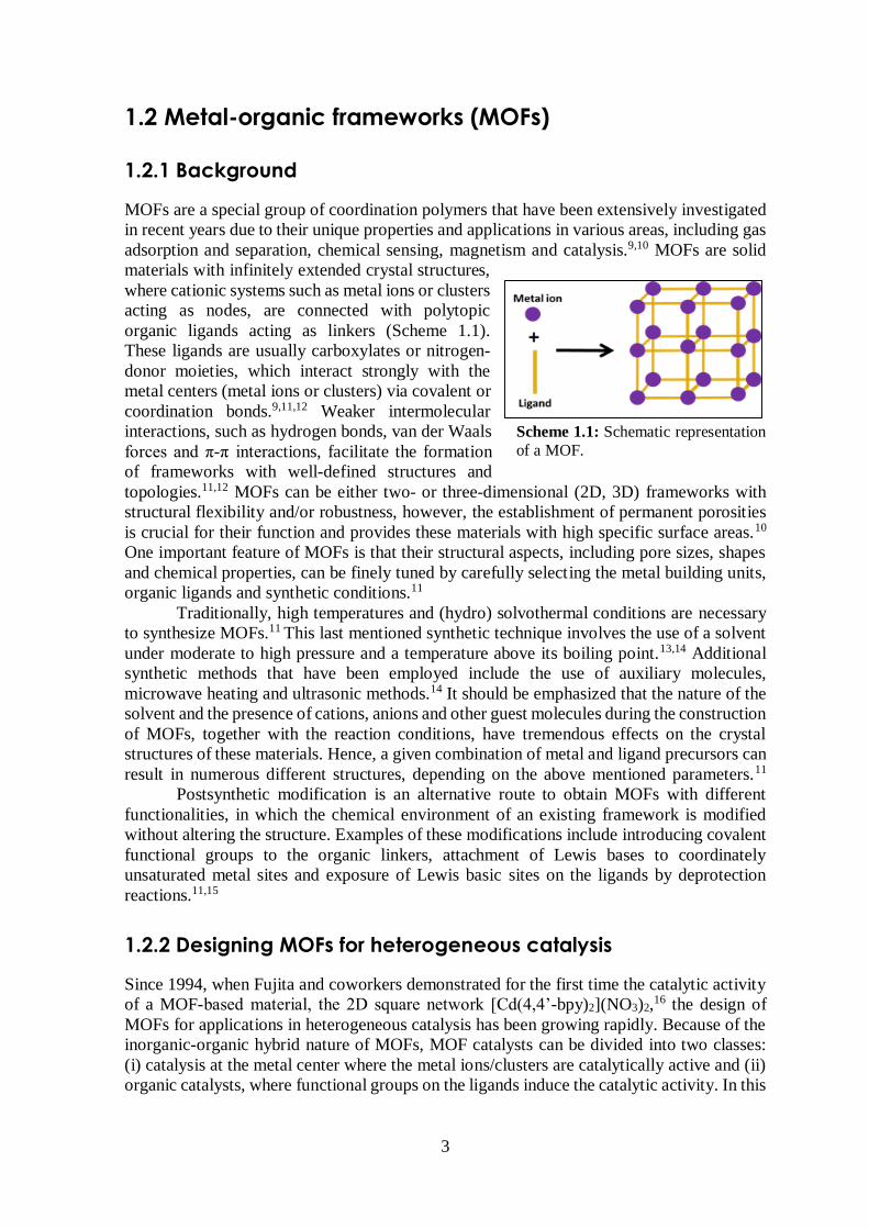
MOFs are a special group of coordination polymers that have been extensively investigated
in recent years due to their unique properties and applications in various areas, including gas
adsorption and separation, chemical sensing, magnetism and catalysis.9,10 MOFs are solid
materials with infinitely extended crystal structures,
where cationic systems such as metal ions or clusters
acting as nodes, are connected with polytopic
organic ligands acting as linkers (Scheme 1.1).
These ligands are usually carboxylates or nitrogen-
donor moieties, which interact strongly with the
metal centers (metal ions or clusters) via covalent or
coordination bonds.9,11,12 Weaker intermolecular
interactions, such as hydrogen bonds, van der Waals
forces and π-π interactions, facilitate the formation
of frameworks with well-defined structures and
topologies.11,12 MOFs can be either two- or three-dimensional (2D, 3D) frameworks with
structural flexibility and/or robustness, however, the establishment of permanent porosities
is crucial for their function and provides these materials with high specific surface areas.10
One important feature of MOFs is that their structural aspects, including pore sizes, shapes
and chemical properties, can be finely tuned by carefully selecting the metal building units,
organic ligands and synthetic conditions.11
Traditionally, high temperatures and (hydro) solvothermal conditions are necessary
to synthesize MOFs.11 This last mentioned synthetic technique involves the use of a solvent
under moderate to high pressure and a temperature above its boiling point.13,14 Additional
synthetic methods that have been employed include the use of auxiliary molecules,
microwave heating and ultrasonic methods.14 It should be emphasized that the nature of the
solvent and the presence of cations, anions and other guest molecules during the construction
of MOFs, together with the reaction conditions, have tremendous effects on the crystal
structures of these materials. Hence, a given combination of metal and ligand precursors can
result in numerous different structures, depending on the above mentioned parameters.11
Postsynthetic modification is an alternative route to obtain MOFs with different
functionalities, in which the chemical environment of an existing framework is modified
without altering the structure. Examples of these modifications include introducing covalent
functional groups to the organic linkers, attachment of Lewis bases to coordinately
unsaturated metal sites and exposure of Lewis basic sites on the ligands by deprotection
reactions.11,15
1.2.2 Designing MOFs for heterogeneous catalysis
Since 1994, when Fujita and coworkers demonstrated for the first time the catalytic activity
of a MOF-based material, the 2D square network [Cd(4,4’-bpy)2](NO3)2,16 the design of
MOFs for applications in heterogeneous catalysis has been growing rapidly. Because of the
inorganic-organic hybrid nature of MOFs, MOF catalysts can be divided into two classes:
(i) catalysis at the metal center where the metal ions/clusters are catalytically active and (ii)
organic catalysts, where functional groups on the ligands induce the catalytic activity. In this
Scheme 1.1: Schematic representation
of a MOF.
4
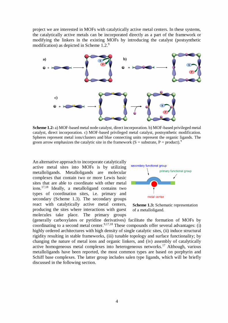
project we are interested in MOFs with catalytically active metal centers. In these systems,
the catalytically active metals can be incorporated directly as a part of the framework or
modifying the linkers in the existing MOFs by introducing the catalyst (postsynthetic
modification) as depicted in Scheme 1.2.9
Scheme 1.2: a) MOF-based metal node catalyst, direct incorporation. b) MOF-based privileged metal catalyst, direct incorporation. c) MOF-based privileged metal catalyst, postsynthetic modification.
Spheres represent metal ions/clusters and blue connecting units represent the organic ligands. The
green arrow emphasizes the catalytic site in the framework (S = substrate, P = product).9
An alternative approach to incorporate catalytically
active metal sites into MOFs is by utilizing
metalloligands. Metalloligands are molecular
complexes that contain two or more Lewis basic
sites that are able to coordinate with other metal
ions.17,18 Ideally, a metalloligand contains two
types of coordination sites, i.e. primary and
secondary (Scheme 1.3). The secondary groups
react with catalytically active metal centers,
producing the sites where interactions with guest
molecules take place. The primary groups
(generally carboxylates or pyridine derivatives) facilitate the formation of MOFs by
coordinating to a second metal center.9,17,18 These compounds offer several advantages: (i)
highly ordered architectures with high density of single catalytic sites, (ii) induce structural
rigidity resulting in stable frameworks, (iii) tunable topology and surface functionality; by
changing the nature of metal ions and organic linkers, and (iv) assembly of catalytically
active homogeneous metal complexes into heterogeneous networks.17 Although, various
metalloligands have been reported, the most common types are based on porphyrin and
Schiff base complexes. The latter group includes salen type ligands, which will be briefly
discussed in the following section.
b)
c)
a)
Scheme 1.3: Schematic representation
of a metalloligand.
5
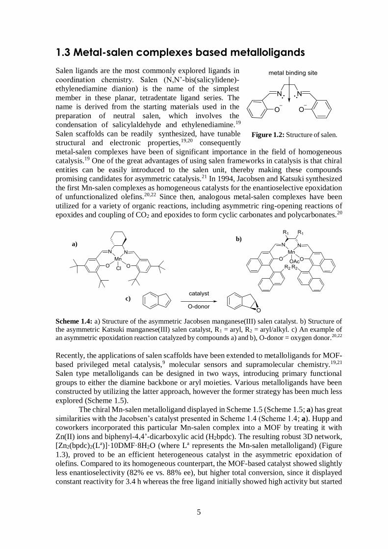
1.3 Metal-salen complexes based metalloligands
Salen ligands are the most commonly explored ligands in
ethylenediamine dianion) is the name of the simplest
member in these planar, tetradentate ligand series. The
name is derived from the starting materials used in the
preparation of neutral salen, which involves the
condensation of salicylaldehyde and ethylenediamine.19
Salen scaffolds can be readily synthesized, have tunable
structural and electronic properties,19,20 consequently
metal-salen complexes have been of significant importance in the field of homogeneous
catalysis.19 One of the great advantages of using salen frameworks in catalysis is that chiral
entities can be easily introduced to the salen unit, thereby making these compounds
promising candidates for asymmetric catalysis.21 In 1994, Jacobsen and Katsuki synthesized
the first Mn-salen complexes as homogeneous catalysts for the enantioselective epoxidation
of unfunctionalized olefins.20,22 Since then, analogous metal-salen complexes have been
utilized for a variety of organic reactions, including asymmetric ring-opening reactions of
epoxides and coupling of CO2 and epoxides to form cyclic carbonates and polycarbonates.20
Scheme 1.4: a) Structure of the asymmetric Jacobsen manganese(III) salen catalyst. b) Structure of the asymmetric Katsuki manganese(III) salen catalyst, R1 = aryl, R2 = aryl/alkyl. c) An example of
an asymmetric epoxidation reaction catalyzed by compounds a) and b), O-donor = oxygen donor.20,22
Recently, the applications of salen scaffolds have been extended to metalloligands for MOF-
based privileged metal catalysis,9 molecular sensors and supramolecular chemistry.19,21
Salen type metalloligands can be designed in two ways, introducing primary functional
groups to either the diamine backbone or aryl moieties. Various metalloligands have been
constructed by utilizing the latter approach, however the former strategy has been much less
explored (Scheme 1.5).
The chiral Mn-salen metalloligand displayed in Scheme 1.5 (Scheme 1.5; a) has great
similarities with the Jacobsen’s catalyst presented in Scheme 1.4 (Scheme 1.4; a). Hupp and
coworkers incorporated this particular Mn-salen complex into a MOF by treating it with
Zn(II) ions and biphenyl-4,4’-dicarboxylic acid (H2bpdc). The resulting robust 3D network,
[Zn2(bpdc)2(La)]·10DMF·8H2O (where La represents the Mn-salen metalloligand) (Figure
1.3), proved to be an efficient heterogeneous catalyst in the asymmetric epoxidation of
olefins. Compared to its homogeneous counterpart, the MOF-based catalyst showed slightly
less enantioselectivity (82% ee vs. 88% ee), but higher total conversion, since it displayed
constant reactivity for 3.4 h whereas the free ligand initially showed high activity but started
Figure 1.2: Structure of salen.
a) b)
c)
6
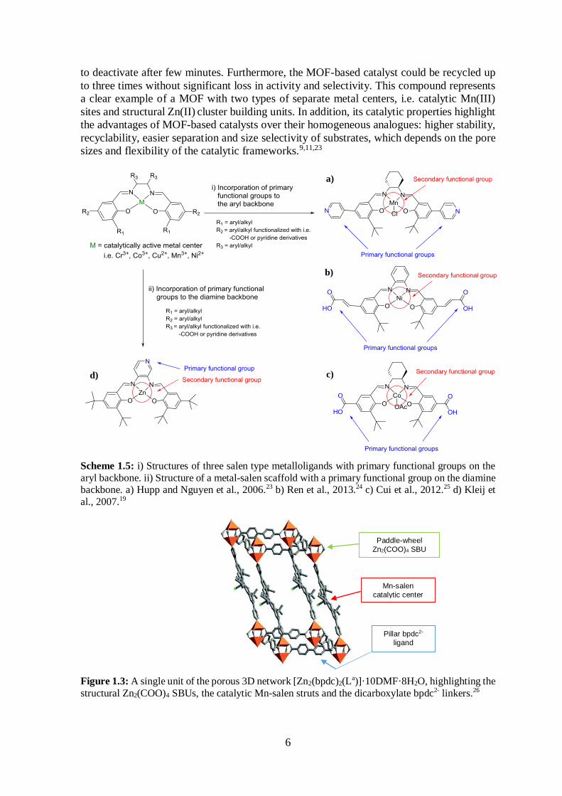
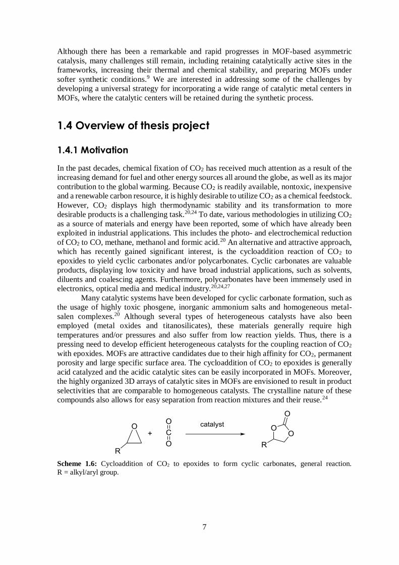
to deactivate after few minutes. Furthermore, the MOF-based catalyst could be recycled up
to three times without significant loss in activity and selectivity. This compound represents
a clear example of a MOF with two types of separate metal centers, i.e. catalytic Mn(III)
sites and structural Zn(II) cluster building units. In addition, its catalytic properties highlight
the advantages of MOF-based catalysts over their homogeneous analogues: higher stability,
recyclability, easier separation and size selectivity of substrates, which depends on the pore
sizes and flexibility of the catalytic frameworks.9,11,23
Scheme 1.5: i) Structures of three salen type metalloligands with primary functional groups on the
aryl backbone. ii) Structure of a metal-salen scaffold with a primary functional group on the diamine backbone. a) Hupp and Nguyen et al., 2006.23 b) Ren et al., 2013.24 c) Cui et al., 2012.25 d) Kleij et
al., 2007.19
Figure 1.3: A single unit of the porous 3D network [Zn2(bpdc)2(La)]·10DMF·8H2O, highlighting the
structural Zn2(COO)4 SBUs, the catalytic Mn-salen struts and the dicarboxylate bpdc2- linkers.26
a)
c)
b)
d)
Paddle-wheel
Zn2(COO)4 SBU
Mn-salen
catalytic center
Pillar bpdc2-
ligand
7
Although there has been a remarkable and rapid progresses in MOF-based asymmetric
catalysis, many challenges still remain, including retaining catalytically active sites in the
frameworks, increasing their thermal and chemical stability, and preparing MOFs under
softer synthetic conditions.9 We are interested in addressing some of the challenges by
developing a universal strategy for incorporating a wide range of catalytic metal centers in
MOFs, where the catalytic centers will be retained during the synthetic process.
1.4 Overview of thesis project
1.4.1 Motivation
In the past decades, chemical fixation of CO2 has received much attention as a result of the
increasing demand for fuel and other energy sources all around the globe, as well as its major
contribution to the global warming. Because CO2 is readily available, nontoxic, inexpensive
and a renewable carbon resource, it is highly desirable to utilize CO2 as a chemical feedstock.
However, CO2 displays high thermodynamic stability and its transformation to more
desirable products is a challenging task.20,24 To date, various methodologies in utilizing CO2
as a source of materials and energy have been reported, some of which have already been
exploited in industrial applications. This includes the photo- and electrochemical reduction
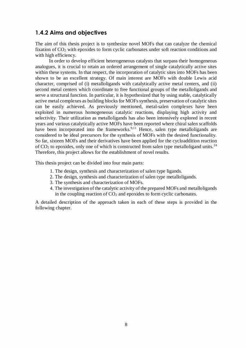
of CO2 to CO, methane, methanol and formic acid.20 An alternative and attractive approach,
which has recently gained significant interest, is the cycloaddition reaction of CO2 to
epoxides to yield cyclic carbonates and/or polycarbonates. Cyclic carbonates are valuable
products, displaying low toxicity and have broad industrial applications, such as solvents,
diluents and coalescing agents. Furthermore, polycarbonates have been immensely used in
electronics, optical media and medical industry.20,24,27
Many catalytic systems have been developed for cyclic carbonate formation, such as
the usage of highly toxic phosgene, inorganic ammonium salts and homogeneous metal-
salen complexes.20 Although several types of heterogeneous catalysts have also been
employed (metal oxides and titanosilicates), these materials generally require high
temperatures and/or pressures and also suffer from low reaction yields. Thus, there is a
pressing need to develop efficient heterogeneous catalysts for the coupling reaction of CO2
with epoxides. MOFs are attractive candidates due to their high affinity for CO2, permanent
porosity and large specific surface area. The cycloaddition of CO2 to epoxides is generally
acid catalyzed and the acidic catalytic sites can be easily incorporated in MOFs. Moreover,
the highly organized 3D arrays of catalytic sites in MOFs are envisioned to result in product
selectivities that are comparable to homogeneous catalysts. The crystalline nature of these
compounds also allows for easy separation from reaction mixtures and their reuse.24
Scheme 1.6: Cycloaddition of CO2 to epoxides to form cyclic carbonates, general reaction.
R = alkyl/aryl group.
8
1.4.2 Aims and objectives
The aim of this thesis project is to synthesize novel MOFs that can catalyze the chemical
fixation of CO2 with epoxides to form cyclic carbonates under soft reaction conditions and
with high efficiency.
In order to develop efficient heterogeneous catalysts that surpass their homogeneous
analogues, it is crucial to retain an ordered arrangement of single catalytically active sites
within these systems. In that respect, the incorporation of catalytic sites into MOFs has been
shown to be an excellent strategy. Of main interest are MOFs with double Lewis acid
character, comprised of (i) metalloligands with catalytically active metal centers, and (ii)
second metal centers which coordinate to free functional groups of the metalloligands and
serve a structural function. In particular, it is hypothesized that by using stable, catalytically
active metal complexes as building blocks for MOFs synthesis, preservation of catalytic sites
can be easily achieved. As previously mentioned, metal-salen complexes have been
exploited in numerous homogeneous catalytic reactions, displaying high activity and
selectivity. Their utilization as metalloligands has also been intensively explored in recent
years and various catalytically active MOFs have been reported where chiral salen scaffolds
have been incorporated into the frameworks.9,11 Hence, salen type metalloligands are
considered to be ideal precursors for the synthesis of MOFs with the desired functionality.
So far, sixteen MOFs and their derivatives have been applied for the cycloaddition reaction
of CO2 to epoxides, only one of which is constructed from salen type metalloligand units.24
Therefore, this project allows for the establishment of novel results.
This thesis project can be divided into four main parts:
1. The design, synthesis and characterization of salen type ligands.
2. The design, synthesis and characterization of salen type metalloligands.
3. The synthesis and characterization of MOFs.
4. The investigation of the catalytic activity of the prepared MOFs and metalloligands
in the coupling reaction of CO2 and epoxides to form cyclic carbonates.
A detailed description of the approach taken in each of these steps is provided in the
following chapter.
9
2 Research Strategy
2.1 The design and synthesis of salen type metalloligands
2.1.1 Target metalloligand unit
As emphasized in Scheme 1.5, a metal-salen complex can be modified into a metalloligand
in two distinct ways, depending on the location of the second functional groups. The less
investigated and simultaneously more challenging approach, involving the modification of
the diamine backbone was chosen for this work (Scheme 1.5). The primary functional groups
we selected was a carboxylate moiety, which are well known for formation of strong metal-
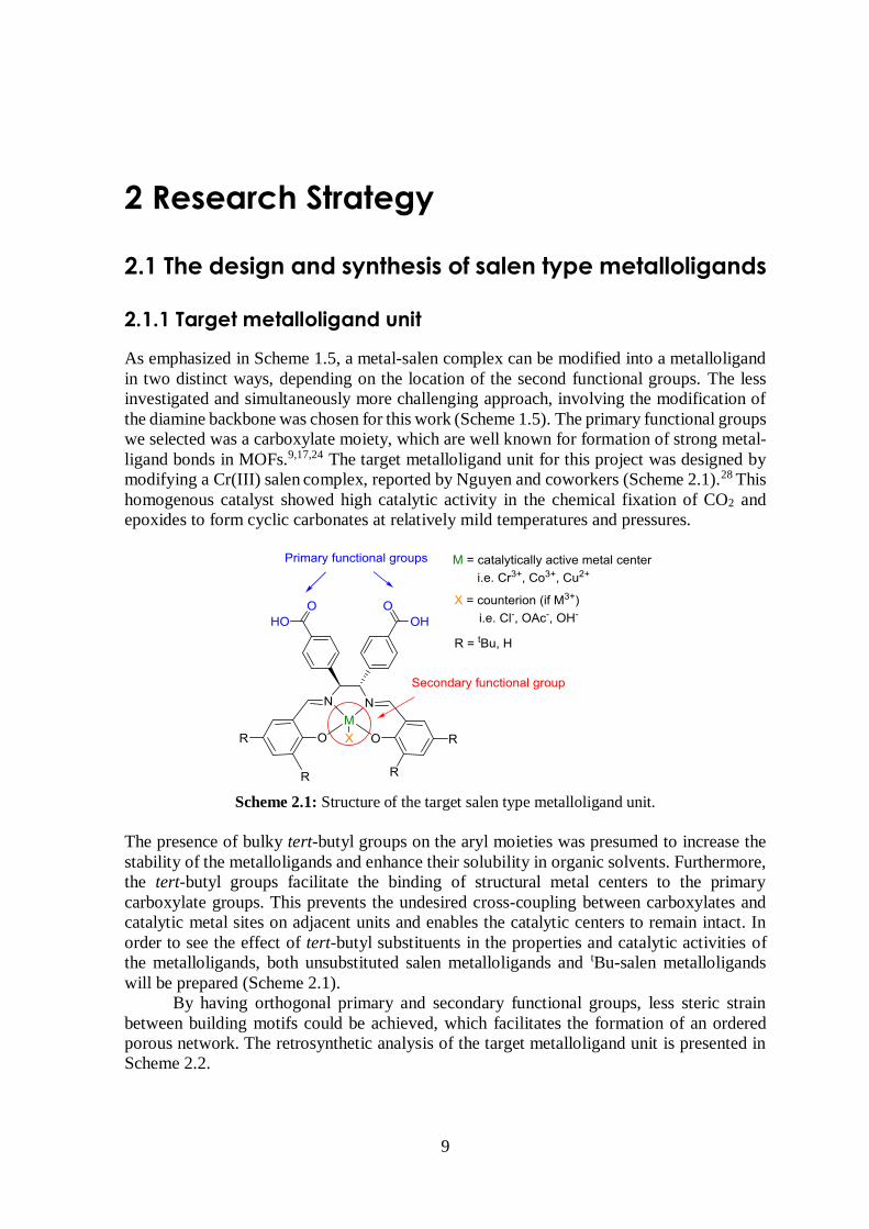
ligand bonds in MOFs.9,17,24 The target metalloligand unit for this project was designed by
modifying a Cr(III) salen complex, reported by Nguyen and coworkers (Scheme 2.1).28 This
homogenous catalyst showed high catalytic activity in the chemical fixation of CO2 and
epoxides to form cyclic carbonates at relatively mild temperatures and pressures.
Scheme 2.1: Structure of the target salen type metalloligand unit.
The presence of bulky tert-butyl groups on the aryl moieties was presumed to increase the
stability of the metalloligands and enhance their solubility in organic solvents. Furthermore,
the tert-butyl groups facilitate the binding of structural metal centers to the primary
carboxylate groups. This prevents the undesired cross-coupling between carboxylates and
catalytic metal sites on adjacent units and enables the catalytic centers to remain intact. In
order to see the effect of tert-butyl substituents in the properties and catalytic activities of
the metalloligands, both unsubstituted salen metalloligands and tBu-salen metalloligands
will be prepared (Scheme 2.1).
By having orthogonal primary and secondary functional groups, less steric strain
between building motifs could be achieved, which facilitates the formation of an ordered
porous network. The retrosynthetic analysis of the target metalloligand unit is presented in
Scheme 2.2.
10
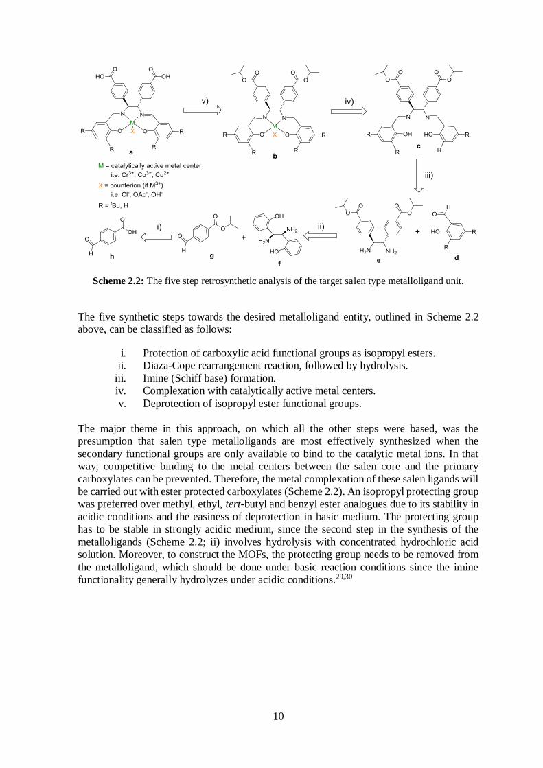
Scheme 2.2: The five step retrosynthetic analysis of the target salen type metalloligand unit.
The five synthetic steps towards the desired metalloligand entity, outlined in Scheme 2.2
above, can be classified as follows:
i. Protection of carboxylic acid functional groups as isopropyl esters.
ii. Diaza-Cope rearrangement reaction, followed by hydrolysis.
iii. Imine (Schiff base) formation.
iv. Complexation with catalytically active metal centers.
v. Deprotection of isopropyl ester functional groups.
The major theme in this approach, on which all the other steps were based, was the
presumption that salen type metalloligands are most effectively synthesized when the
secondary functional groups are only available to bind to the catalytic metal ions. In that
way, competitive binding to the metal centers between the salen core and the primary
carboxylates can be prevented. Therefore, the metal complexation of these salen ligands will
be carried out with ester protected carboxylates (Scheme 2.2). An isopropyl protecting group
was preferred over methyl, ethyl, tert-butyl and benzyl ester analogues due to its stability in
acidic conditions and the easiness of deprotection in basic medium. The protecting group
has to be stable in strongly acidic medium, since the second step in the synthesis of the
metalloligands (Scheme 2.2; ii) involves hydrolysis with concentrated hydrochloric acid
solution. Moreover, to construct the MOFs, the protecting group needs to be removed from
the metalloligand, which should be done under basic reaction conditions since the imine
functionality generally hydrolyzes under acidic conditions.29,30
11
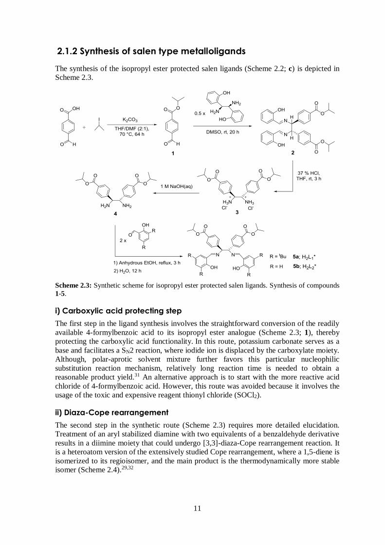
2.1.2 Synthesis of salen type metalloligands
The synthesis of the isopropyl ester protected salen ligands (Scheme 2.2; c) is depicted in
Scheme 2.3.
Scheme 2.3: Synthetic scheme for isopropyl ester protected salen ligands. Synthesis of compounds
1-5.
i) Carboxylic acid protecting step
The first step in the ligand synthesis involves the straightforward conversion of the readily
available 4-formylbenzoic acid to its isopropyl ester analogue (Scheme 2.3; 1), thereby
protecting the carboxylic acid functionality. In this route, potassium carbonate serves as a
base and facilitates a SN2 reaction, where iodide ion is displaced by the carboxylate moiety.
Although, polar-aprotic solvent mixture further favors this particular nucleophilic
substitution reaction mechanism, relatively long reaction time is needed to obtain a
reasonable product yield.31 An alternative approach is to start with the more reactive acid
chloride of 4-formylbenzoic acid. However, this route was avoided because it involves the
usage of the toxic and expensive reagent thionyl chloride (SOCl2).
ii) Diaza-Cope rearrangement
The second step in the synthetic route (Scheme 2.3) requires more detailed elucidation.
Treatment of an aryl stabilized diamine with two equivalents of a benzaldehyde derivative
results in a diimine moiety that could undergo [3,3]-diaza-Cope rearrangement reaction. It
is a heteroatom version of the extensively studied Cope rearrangement, where a 1,5-diene is
isomerized to its regioisomer, and the main product is the thermodynamically more stable
isomer (Scheme 2.4).29,32
12
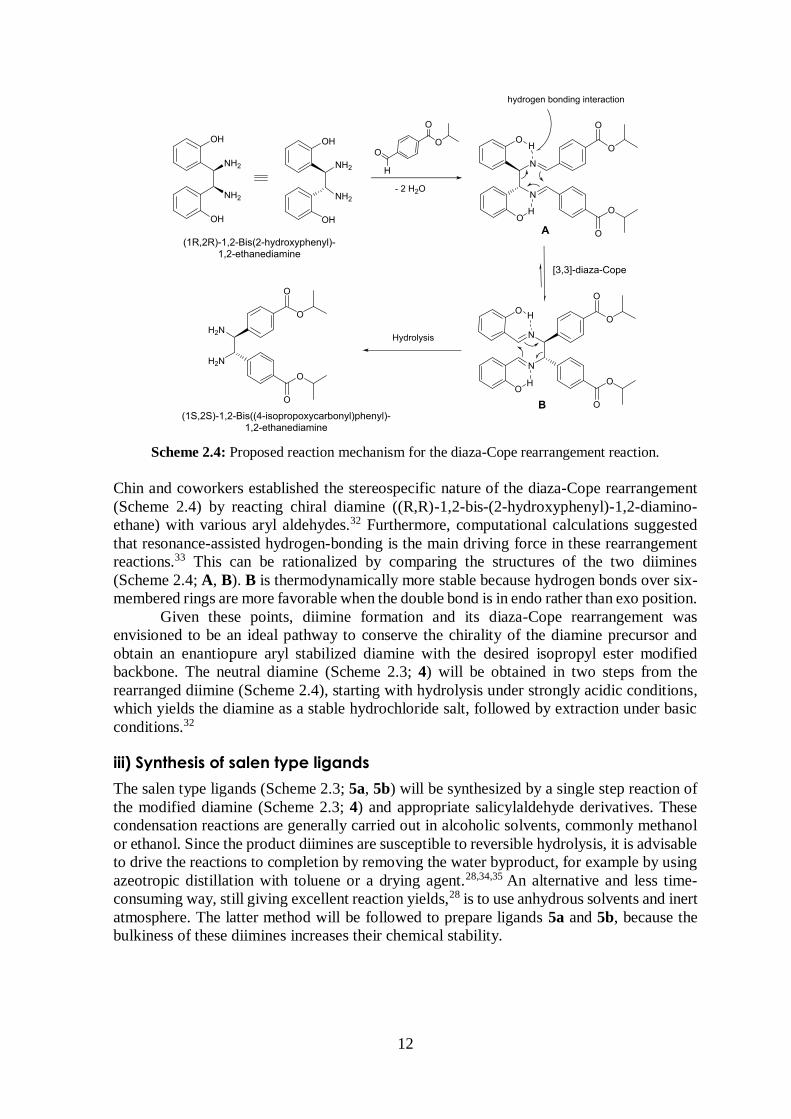
Scheme 2.4: Proposed reaction mechanism for the diaza-Cope rearrangement reaction.
Chin and coworkers established the stereospecific nature of the diaza-Cope rearrangement
(Scheme 2.4) by reacting chiral diamine ((R,R)-1,2-bis-(2-hydroxyphenyl)-1,2-diamino-
ethane) with various aryl aldehydes.32 Furthermore, computational calculations suggested
that resonance-assisted hydrogen-bonding is the main driving force in these rearrangement
reactions.33 This can be rationalized by comparing the structures of the two diimines
(Scheme 2.4; A, B). B is thermodynamically more stable because hydrogen bonds over six-
membered rings are more favorable when the double bond is in endo rather than exo position.
Given these points, diimine formation and its diaza-Cope rearrangement was
envisioned to be an ideal pathway to conserve the chirality of the diamine precursor and
obtain an enantiopure aryl stabilized diamine with the desired isopropyl ester modified
backbone. The neutral diamine (Scheme 2.3; 4) will be obtained in two steps from the
rearranged diimine (Scheme 2.4), starting with hydrolysis under strongly acidic conditions,
which yields the diamine as a stable hydrochloride salt, followed by extraction under basic
conditions.32
iii) Synthesis of salen type ligands
The salen type ligands (Scheme 2.3; 5a, 5b) will be synthesized by a single step reaction of
the modified diamine (Scheme 2.3; 4) and appropriate salicylaldehyde derivatives. These
condensation reactions are generally carried out in alcoholic solvents, commonly methanol
or ethanol. Since the product diimines are susceptible to reversible hydrolysis, it is advisable
to drive the reactions to completion by removing the water byproduct, for example by using
azeotropic distillation with toluene or a drying agent.28,34,35 An alternative and less time-
consuming way, still giving excellent reaction yields,28 is to use anhydrous solvents and inert
atmosphere. The latter method will be followed to prepare ligands 5a and 5b, because the
bulkiness of these diimines increases their chemical stability.
13
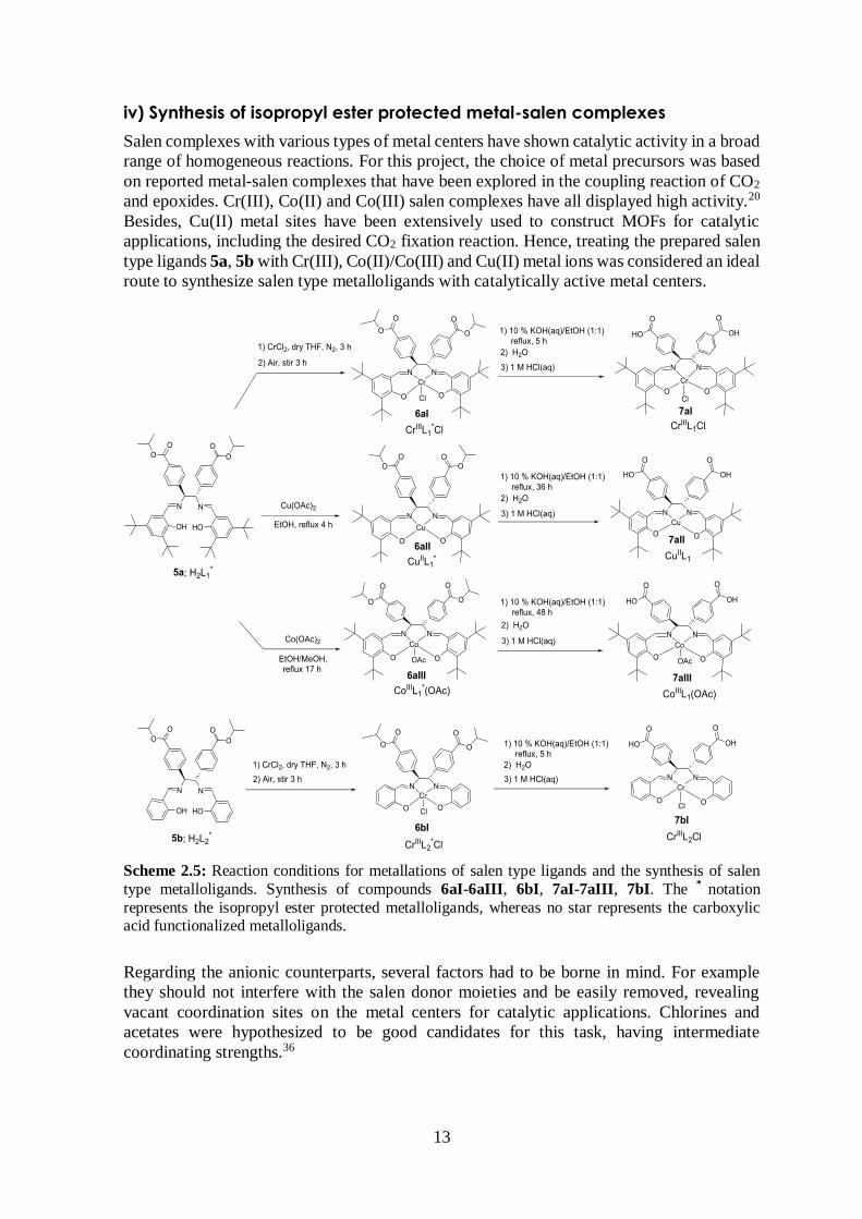
iv) Synthesis of isopropyl ester protected metal-salen complexes
Salen complexes with various types of metal centers have shown catalytic activity in a broad
range of homogeneous reactions. For this project, the choice of metal precursors was based
on reported metal-salen complexes that have been explored in the coupling reaction of CO2
and epoxides. Cr(III), Co(II) and Co(III) salen complexes have all displayed high activity.20
Besides, Cu(II) metal sites have been extensively used to construct MOFs for catalytic
applications, including the desired CO2 fixation reaction. Hence, treating the prepared salen
type ligands 5a, 5b with Cr(III), Co(II)/Co(III) and Cu(II) metal ions was considered an ideal
route to synthesize salen type metalloligands with catalytically active metal centers.
Scheme 2.5: Reaction conditions for metallations of salen type ligands and the synthesis of salen
type metalloligands. Synthesis of compounds 6aI-6aIII, 6bI, 7aI-7aIII, 7bI. The *
notation
represents the isopropyl ester protected metalloligands, whereas no star represents the carboxylic acid functionalized metalloligands.
Regarding the anionic counterparts, several factors had to be borne in mind. For example
they should not interfere with the salen donor moieties and be easily removed, revealing
vacant coordination sites on the metal centers for catalytic applications. Chlorines and
acetates were hypothesized to be good candidates for this task, having intermediate
coordinating strengths.36
14
Two different synthetic routes will be followed to prepare the isopropyl ester
protected metal-salen complexes, as illustrated in Scheme 2.5. The synthesis of Cr(III)-salen
complexes is based on a literature procedure, where 95% yield was accomplished in dry
refluxing THF.28 On the other hand, preparation of the Co and Cu analogues involves
refluxing in alcoholic solvents (methanol, ethanol) under aerobic conditions.
v) Deprotection of isopropyl ester functional groups
As mentioned in section 2.1.1, the isopropyl ester group was chosen partly because it was
hypothesized to be cleaved relatively easily in basic medium. Afterwards, by acidifying the
reaction mixture the neutral metalloligand will be isolated (Scheme 2.5).
2.2 The synthesis and characterization of MOFs
The preparation of MOFs will be explored using several liquid-phase synthetic techniques.
The synthetic parameters, such as molar ratios of starting materials, solvent, reaction time,
temperature and pressure will be varied in order to evaluate their effect on the formation of
MOFs.9 Solvents that are commonly encountered in liquid-phase MOFs synthesis, for
example ethanol, methanol, DMA and DMF will be of main focus.37 Wide range of metal
centers, for instance alkaline, transition metals and rare-earth metals, have been successfully
used in the preparation of MOFs.11 In this research, four metal ions with different properties
were selected: Ca(II), La(III), Cu(II) and Zn(II). The hard nature of the former two was
envisioned to be favorable for interactions with the primary carboxylates on the
metalloligand backbone. The latter two metal ions have been extensively used for
construction of MOFs, Zn(II) cations generally act as structural elements, whereas Cu(II)
are also accessible for interaction with guest molecules and were hypothesized to enhance
the catalytic activity of the prepared frameworks.11 Similarly, as for the preparation of salen
type metalloligands, weakly coordinating counterions, for example nitrate, are most suitable.
Since MOFs are crystalline materials which are generally insoluble in most of the organic
solvents, it is interesting to grow crystals suitable for X-ray diffraction analysis to get the
structural information.9
2.3 Investigation of the catalytic activity of metalloligands
and MOFs
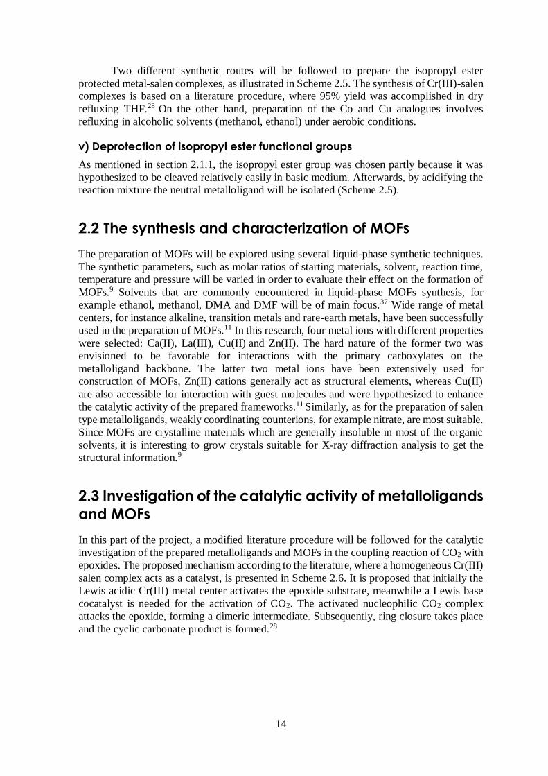
In this part of the project, a modified literature procedure will be followed for the catalytic
investigation of the prepared metalloligands and MOFs in the coupling reaction of CO2 with
epoxides. The proposed mechanism according to the literature, where a homogeneous Cr(III)
salen complex acts as a catalyst, is presented in Scheme 2.6. It is proposed that initially the
Lewis acidic Cr(III) metal center activates the epoxide substrate, meanwhile a Lewis base
cocatalyst is needed for the activation of CO2. The activated nucleophilic CO2 complex
attacks the epoxide, forming a dimeric intermediate. Subsequently, ring closure takes place
and the cyclic carbonate product is formed.28
15
Scheme 2.6: Proposed mechanism for the coupling reaction of CO2 with epoxides, with
homogeneous Cr(III) salen metal complex (Cr-Cl) acting as a catalyst. B = Lewis base cocatalyst,
R = alkyl/aryl group.28
The conversion of CO2 will be evaluated at different reaction conditions, such as normal
atmospheric pressure, high pressure, room temperature and slightly elevated temperature.
Two epoxides with different physical properties were chosen as substrates for the catalytic
reaction, namely the volatile propylene oxide and the more stable styrene oxide. The former
is more reactive, while analysis of the latter is more easily accomplished, since its stability
allows for additional analytical methods for its determination.20,28
16
3 Experimental Section
3.1 General considerations
3.1.1 Reagents and solvents
All manipulations were carried out under normal atmospheric pressure unless otherwise
specified. Standard Schlenck technique and an inert atmosphere of dry nitrogen were used
for the preparation of compounds 5a, 5b, 6aI and 6bI. CrCl2 was handled in the glovebox
under an atmosphere of dry nitrogen.
All purchased chemicals and non-dried solvents were reagent grade or better and
were used without further purification unless indicated otherwise. Moisture sensitive
reactions were carried out in freshly distilled solvents that were dried using appropriate
drying agents. Ethanol was dried over magnesium ethoxide and distilled twice under dry
nitrogen atmosphere before use. Magnesium ethoxide was prepared by treating dried
magnesium turnings with solid iodine in a minimum amount of ethanol.38 THF was dried
over sodium wire in presence of benzophenone under dry nitrogen atmosphere. Chloroform
was dried over P2O5 under dry nitrogen atmosphere. The chemicals: 4-formylbenzoic acid,
and small dark particles precipitated in the presence of CO2. The filtrate was both analyzed
by GC and GC-MS.
Attempt 2: The procedure described above was applied to a solution of 7aI (0.031 g, 0.038
mmol) and 4-dimethylaminopyridine (0.0047 g, 0.038 mmol) in dry chloroform (0.5 mL)
after vacuum heat-treatment (activation of catalyst) of the metalloligand 7aI at 90 °C for 30
min. Substrate: Propylene oxide (3.32 g, 57.2 mmol). Reaction time: 4 h. Observations: No
change observed after treatment with CO2.
Attempt 3: The procedure described above was applied to a solution of 7aI (0.031 g, 0.038
mmol) and 4-dimethylaminopyridine (0.0047 g, 0.038 mmol) in dry chloroform (0.5 mL)
after vacuum heat-treatment (activation of catalyst) of the metalloligand 7aI at 100 °C for
30 min. Substrate: Styrene oxide (7.20 g, 60.0 mmol). Reaction time: 6 h. Observations: No
change observed after treatment with CO2.
Attempt 4: A similar procedure as described above was applied to a heterogeneous
suspension of a coordination polymer (Table 4.7; Experiment 2; 0.0087 g) and 4-dimethyl-
aminopyridine (0.0015 g, 0.012 mmol) in neat epoxide after vacuum heat-treatment
(activation of catalyst) of the coordination polymer at 100 °C for 30 min. Substrate:
Propylene oxide (1.66 g, 28.6 mmol). Reaction time: 6 h. Observations: The propylene oxide
was completely evaporated after treatment with CO2, leaving the solid starting materials
behind.
26
4 Results and Discussion
As mentioned in previous chapters, this thesis is divided into four parts: (1) organic synthesis
of salen type ligands, (2) inorganic synthesis of metalloligands, (3) the construction of
MOFs, and (4) catalytic investigation of the prepared compounds. In this chapter, the results
of each of these steps are reported and discussed in separate sections.
4.1 Synthesis and characterization of isopropyl ester
protected salen type ligands
In the organic synthetic part of this project all compounds were synthesized according to
literature procedures with slight modifications, such as changing solvents, reaction times and
temperatures, or stoichiometric ratios of reactants. All products (Scheme 2.3) were
characterized by 1H and 13C NMR analysis and new compounds (Scheme 2.3; 2-5) were also
analyzed by IR and ESI-MS with one exception, i.e. the mass of the diamine hydrochloride
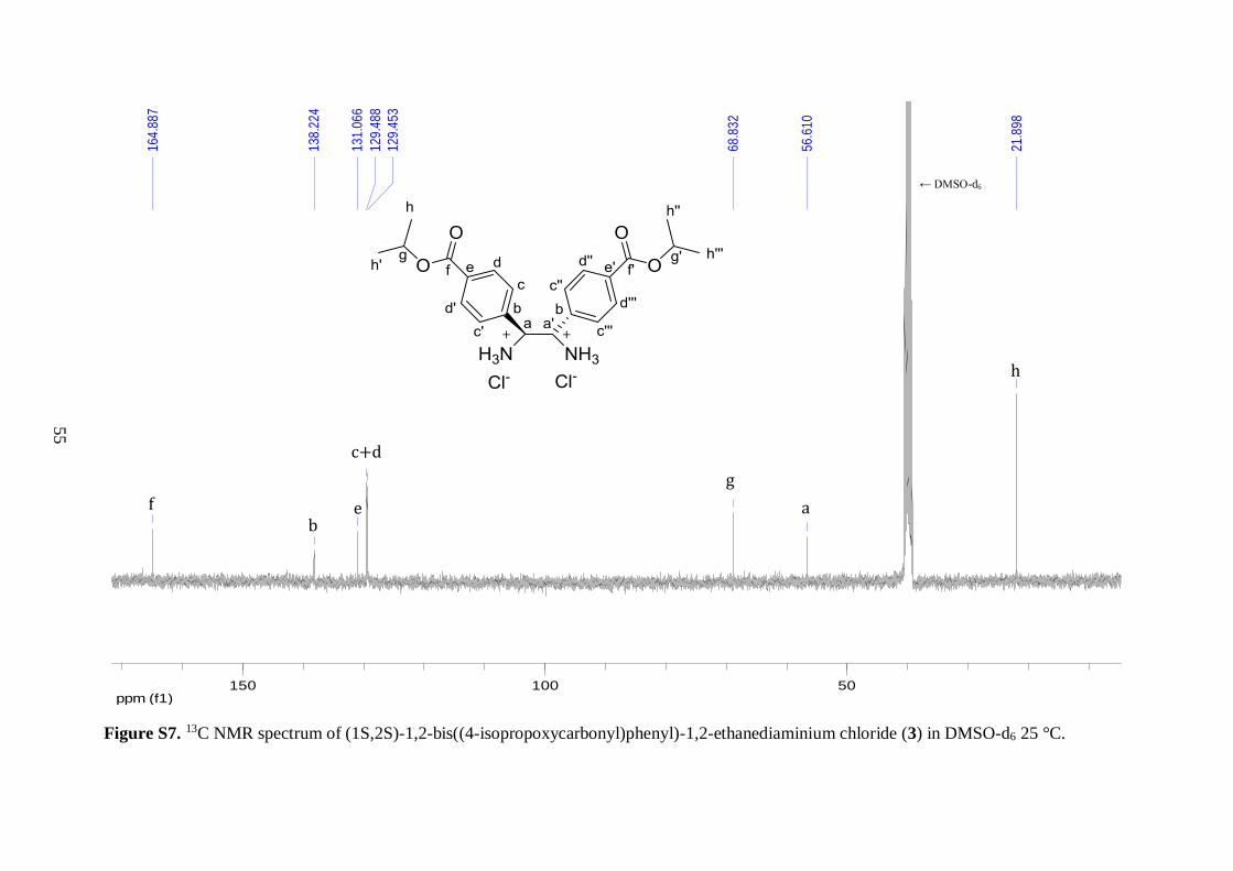
salt (Scheme 2.3; 3) was not recorded. In the following sections the main results of each
synthetic step are presented and discussed.
4.1.1 The carboxylic acid protecting step
As mentioned in the strategy chapter, the isopropyl group was chosen for the protection of a
carboxylic acid and it was introduced by reacting the acid with 2-iodopropane and K2CO3 in
a solvent mixture (THF and DMF). The reaction was carried out several times and the yield
was consistent (above 80%) in all the batches. Interestingly, when the 2-iodopropane reagent
was added in two portions, i.e. half of the amount initially and the remaining half after
refluxing the reaction mixture for 24 h, the yield increased to 94%. The esterified product
was easily separated from the reaction mixture as a yellow solution, leaving behind large
amounts of white precipitate, both KI byproduct and some unreacted K2CO3 base. After
work-up and removal of the residual DMF solvent, isopropyl 4-formylbenzoate (Scheme
2.3; 1) was isolated as an orange solid.
TLC analysis displayed a single spot with large Rf value as compared to the
carboxylic acid starting material, which barely moved in the 60:40 hexane/ethyl acetate
mobile phase. These findings were in good agreement with the exchange of a polar acid
functionality for a less polar ester group. NMR analysis revealed no trace of the starting
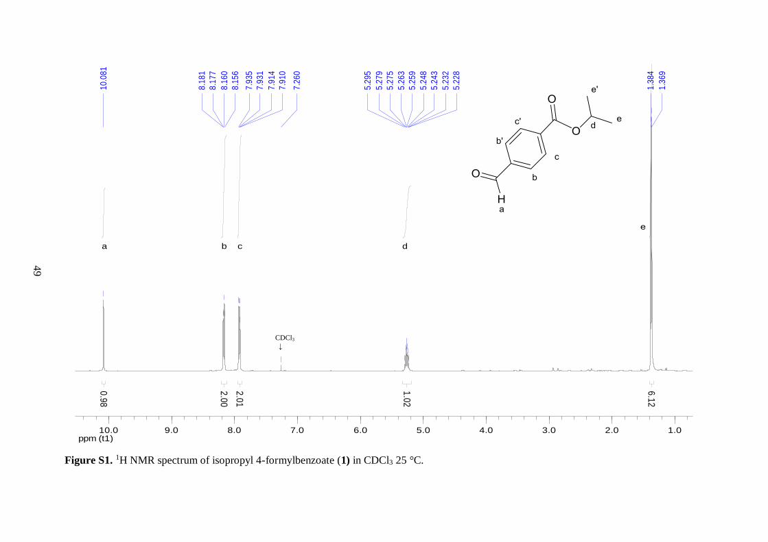
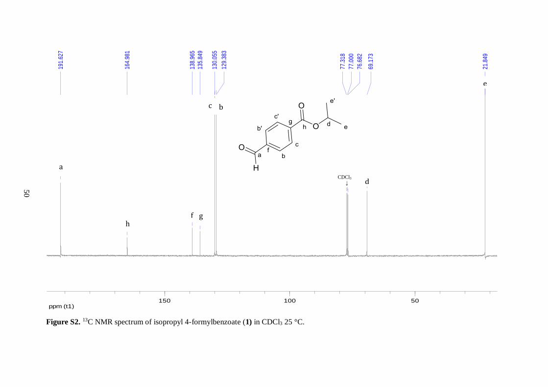
materials thereby confirming the formation of desired compound 1. In the 13C NMR of 1,
the two characteristic resonances from the tertiary carbon and two methyl carbons of the
isopropyl group were observed at 69.2 and 21.8 ppm, respectively. The downfield chemical
shift of the tertiary carbon peak illustrated the presence of a C–O single bond. Similarly, the 1H NMR spectrum of 1 displayed a septet peak for the –CH proton of the isopropyl ester
moiety due to coupling to six methyl protons. As expected, this peak was shifted downfield
because of bonding to the electronegative oxygen. The methyl protons exhibited a doublet
signal due to coupling to the single –CH proton with a coupling constant of 6.4 Hz, which is
27
typical for a three-bond proton-proton coupling in alkyl chains.42 Two doublets, displaying
second-order effects, were observed around 8 ppm in the 1H NMR spectrum of 1. This
splitting pattern is characteristic for asymmetric para-substituted aromatic compounds. In
addition, the peaks further downfield in both the 1H and 13C NMR spectra of 1 were assigned
to the aldehyde group, both chemical shifts were in good agreement with literature values.42
These findings demonstrated that the aldehyde group remained intact during the course of
the reaction.
After successfully protecting the carboxylic acid functionality as an isopropyl ester,
the other substituent on the aryl ring, namely the aldehyde functional group, could be
modified. This was achieved by diimine formation followed by a diaza-Cope rearrangement
reaction.
4.1.2 Diimine formation and the diaza-Cope rearrangement
As depicted in Scheme 2.3, the diimine (2) was prepared by stirring a solution of the chiral
diamine reagent (1R,2R)-1,2-bis(2-hydroxyphenyl)ethylenediamine and aryl aldehyde 1
(1:2.5 molar ratio) in DMSO solvent at room temperature. The reaction mixture was poured
into water to afford 2 as a light yellow precipitate. Interestingly, the color turned light orange
after drying.
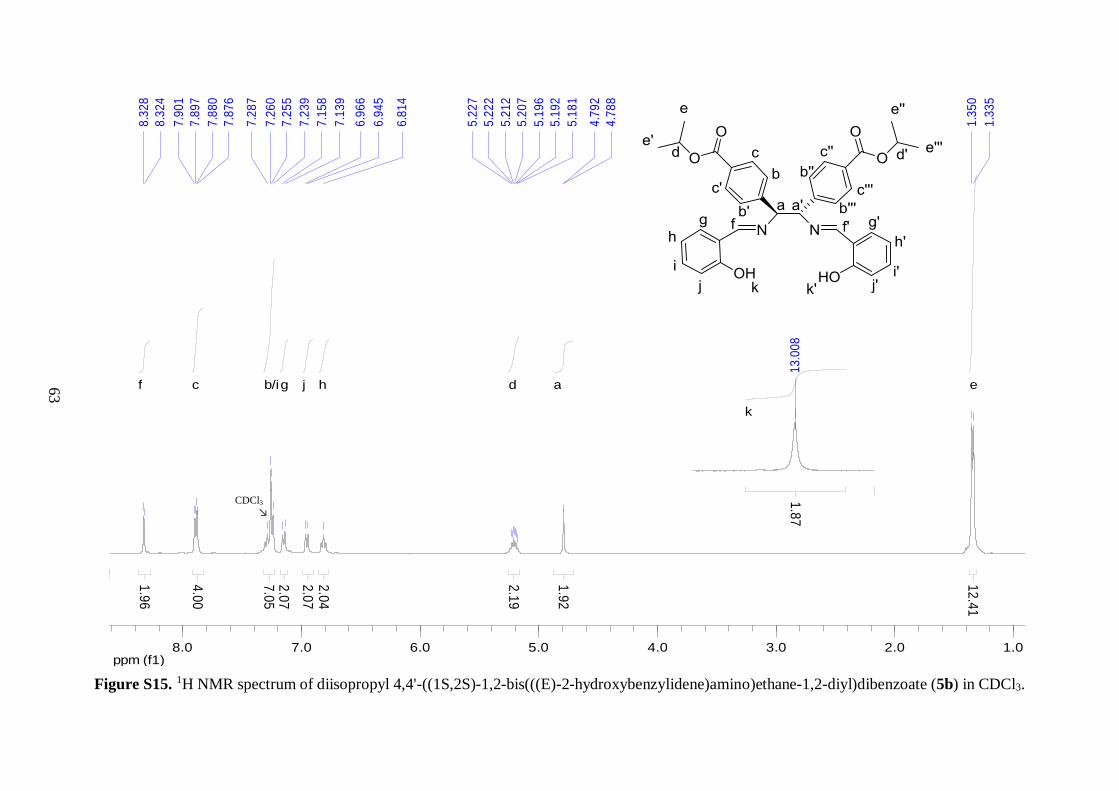
1H NMR spectroscopy revealed that the desired diimine product was formed,
however compound 1 was present as 25% impurities, as judged by peak integration in the 1H NMR spectrum. This was further evident from more than quantitative yield obtained from
this reaction. Nevertheless, this was expected because slight excess of 1 was used in the
reaction. In order to obtain clean NMR spectra of 2, a preparatory TLC was run in 20:80
ethyl acetate/hexane mobile phase. Good band separation was obtained, where the product
2 proved to be less polar than 1. The recorded NMR spectra of the isolated compound from
TLC showed no sign of impurities from 1.
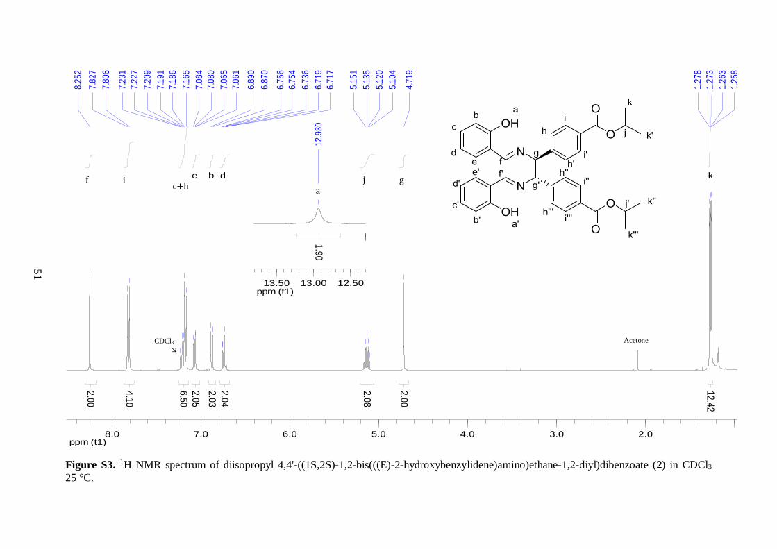
1H NMR analysis provided valuable information related to the structure of 2.
Integration of all the peaks in the spectrum matched well, giving in total 36 protons. Still,
the two overlapping peaks around 7.17 ppm, which corresponded to one proton environment
on the aryl ester backbone (h) and another from the phenol moieties (c), gave slightly higher
integration than expected, presumably because of interference with the residual solvent peak
(CDCl3). The two phenolic protons displayed a broad peak at 12.93 ppm, which was shifted
downfield as compared to normal phenol because of hydrogen bonding interactions with the
imine nitrogens. The peak at 8.25 ppm integrated for two protons and was assigned to the
imine hydrogens.42 The two doublets derived from the aromatic protons on the ester
functionalized benzene rings were shifted upfield with respect to their location in the
spectrum of 1. This observation was in good agreement with the different electronic
environments present in compound 1 and 2. In 2, an alkyl entity has replaced the more
electron withdrawing aldehyde group, leaving both proton environments on the aromatic
ring more shielded.
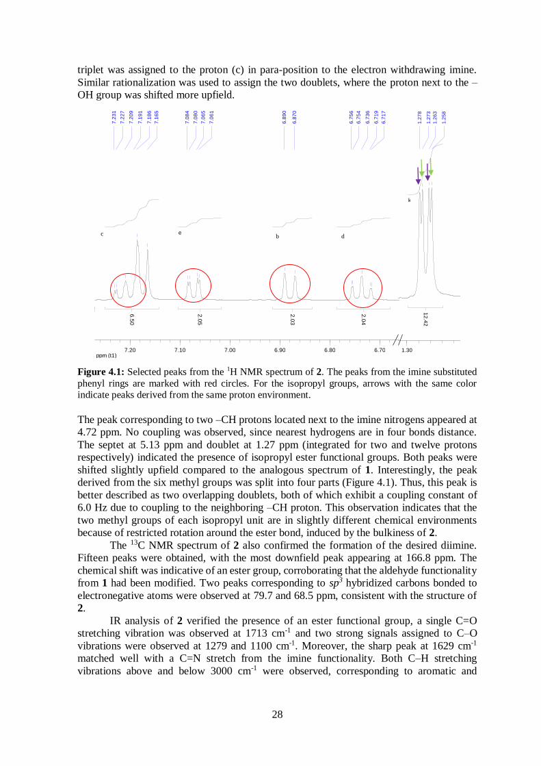
Both the splitting patterns and chemical shift values were used to assign the four
proton environments on the imine substituted phenyl rings. The chemical shifts of these
peaks ranged from 6.7 to 7.2 ppm, and a magnification of the peaks is displayed in Figure
4.1. If small meta-coupling is overlooked, the four peaks highlighted on the left side in
Figure 4.1 can be considered as two triplets and two doublets, in good agreement with ortho-
substituted benzene rings where the two substituents are different. The triplets arise from
coupling to two adjacent ortho-protons on the phenyl rings. The upfield triplet was assigned
to the proton (d) in para-position to the electron donating –OH group, while the downfield
28
triplet was assigned to the proton (c) in para-position to the electron withdrawing imine.
Similar rationalization was used to assign the two doublets, where the proton next to the –
OH group was shifted more upfield.
Figure 4.1: Selected peaks from the 1H NMR spectrum of 2. The peaks from the imine substituted
phenyl rings are marked with red circles. For the isopropyl groups, arrows with the same color indicate peaks derived from the same proton environment.
The peak corresponding to two –CH protons located next to the imine nitrogens appeared at
4.72 ppm. No coupling was observed, since nearest hydrogens are in four bonds distance.
The septet at 5.13 ppm and doublet at 1.27 ppm (integrated for two and twelve protons
respectively) indicated the presence of isopropyl ester functional groups. Both peaks were
shifted slightly upfield compared to the analogous spectrum of 1. Interestingly, the peak
derived from the six methyl groups was split into four parts (Figure 4.1). Thus, this peak is
better described as two overlapping doublets, both of which exhibit a coupling constant of
6.0 Hz due to coupling to the neighboring –CH proton. This observation indicates that the
two methyl groups of each isopropyl unit are in slightly different chemical environments
because of restricted rotation around the ester bond, induced by the bulkiness of 2.
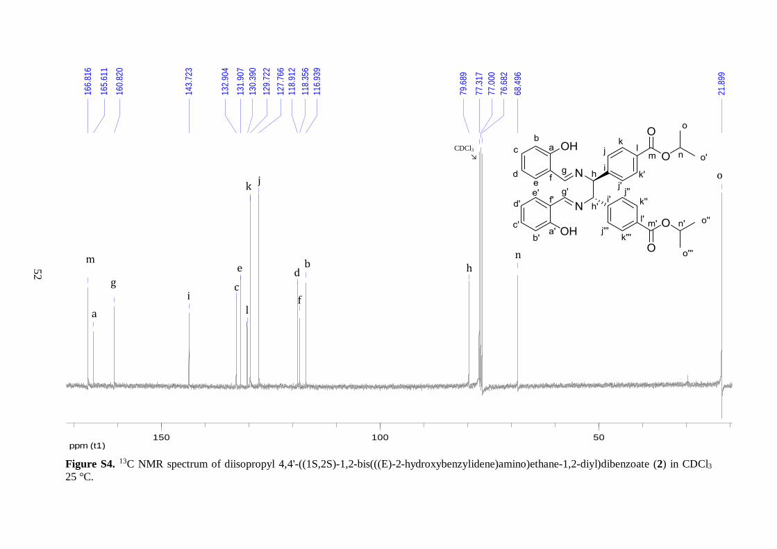
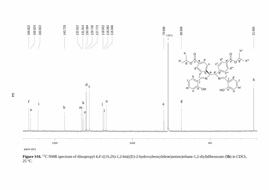
The 13C NMR spectrum of 2 also confirmed the formation of the desired diimine.
Fifteen peaks were obtained, with the most downfield peak appearing at 166.8 ppm. The
chemical shift was indicative of an ester group, corroborating that the aldehyde functionality
from 1 had been modified. Two peaks corresponding to sp3 hybridized carbons bonded to
electronegative atoms were observed at 79.7 and 68.5 ppm, consistent with the structure of
2.
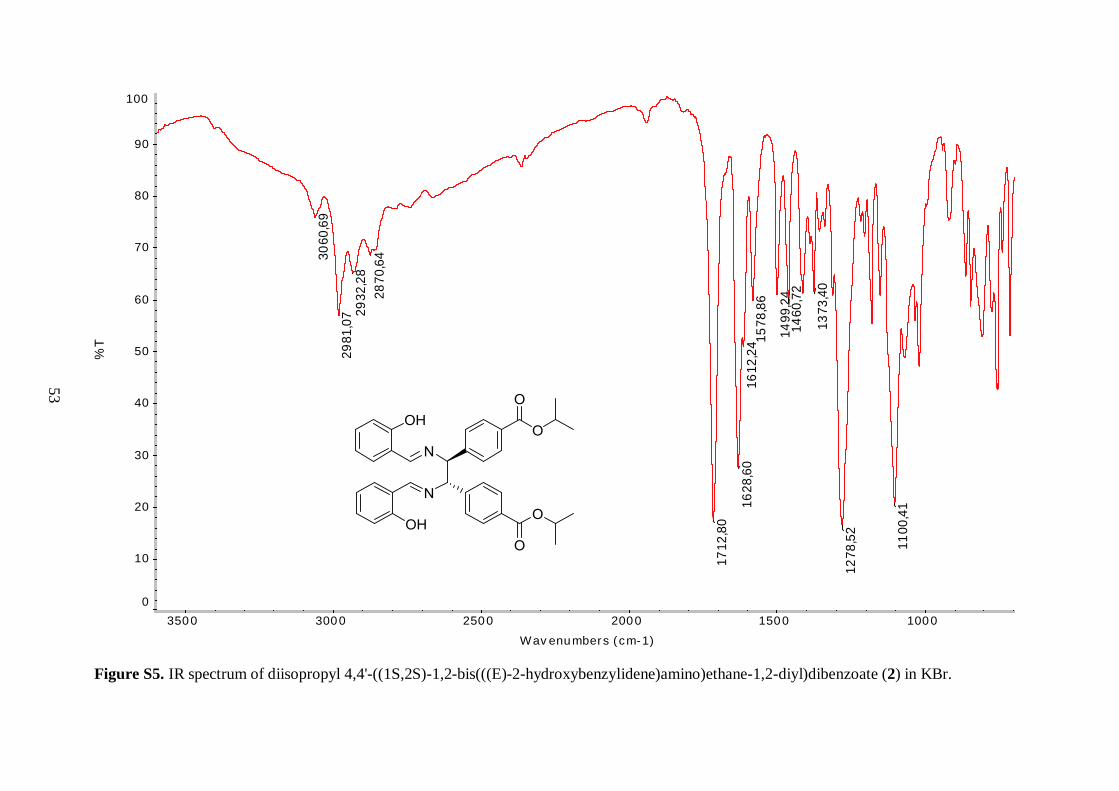
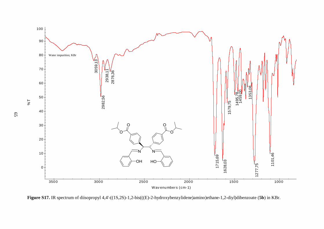
IR analysis of 2 verified the presence of an ester functional group, a single C=O
stretching vibration was observed at 1713 cm-1 and two strong signals assigned to C–O
vibrations were observed at 1279 and 1100 cm-1. Moreover, the sharp peak at 1629 cm-1
matched well with a C=N stretch from the imine functionality. Both C–H stretching
vibrations above and below 3000 cm-1 were observed, corresponding to aromatic and
ppm (t1)6.606.706.806.907.007.107.20
7.2
31
7.2
27
7.2
09
7.1
91
7.1
86
7.1
65
7.0
84
7.0
80
7.0
65
7.0
61
6.8
90
6.8
70
6.7
56
6.7
54
6.7
36
6.7
19
6.7
17
6.5
0
2.0
5
e
2.0
3
d
2.0
4
b
ppm (t1)1.001.101.201.301.401.50
1.2
78
1.2
73
1.2
63
1.2
58
12
.42
k
ppm (t1)6.606.706.806.907.007.107.20
7.2
31
7.2
27
7.2
09
7.1
91
7.1
86
7.1
65
7.0
84
7.0
80
7.0
65
7.0
61
6.8
90
6.8
70
6.7
56
6.7
54
6.7
36
6.7
19
6.7
17
6.5
0
2.0
5
e
2.0
3
d
2.0
4
b
c b d
29
aliphatic environments, respectively. The medium bands in the region 1461-1612 cm-1 were
also indicative of the presence of aromatic rings, derived from C=C resonances. No distinct
O–H stretching vibration was present in the spectrum of 2, still the –OH functional groups
were assumed to cause the broadness observed between 2300 and 3400 cm-1.
The final proof of the successful isolation of 2 was obtained from ESI-MS analysis.
The most intense peak at 593.2646 m/z corresponded to the singly protonated molecular ion,
which was in good agreement with the calculated value 592.2573 m/z for the neutral
compound. In addition, these findings illustrate that 2 is a relatively stable compound, since
the peaks derived from the fragment ions displayed much lower intensity.
Thus, the diaza-Cope rearrangement reaction turned out to be a good way to
incorporate isopropyl ester functionalized aryl rings to the diamine backbone. Even though
2 is indeed a salen type ligand, since it exhibits the salen core, additional steps were needed
to introduce the desired substituents to the aryl backbone. Diimine 2 was synthesized in good
yield and the impurities from 1 were not envisioned to interfere with subsequent steps.
Therefore it was decided to proceed to the hydrolysis step without further purification of the
product mixture.
4.1.3 Hydrolysis and basification
The hydrolysis of 2 was carried out under strongly acidic conditions, by the addition of a
concentrated hydrochloric acid solution to a THF solution of 2 (Scheme 2.3). The diamine
was first isolated as a white hydrochloride salt (3) because of the acidic environment. The
reaction proceeded well and the product yield was 72%, which was similar to literature
values with electron withdrawing substituents on the diamine backbone.32
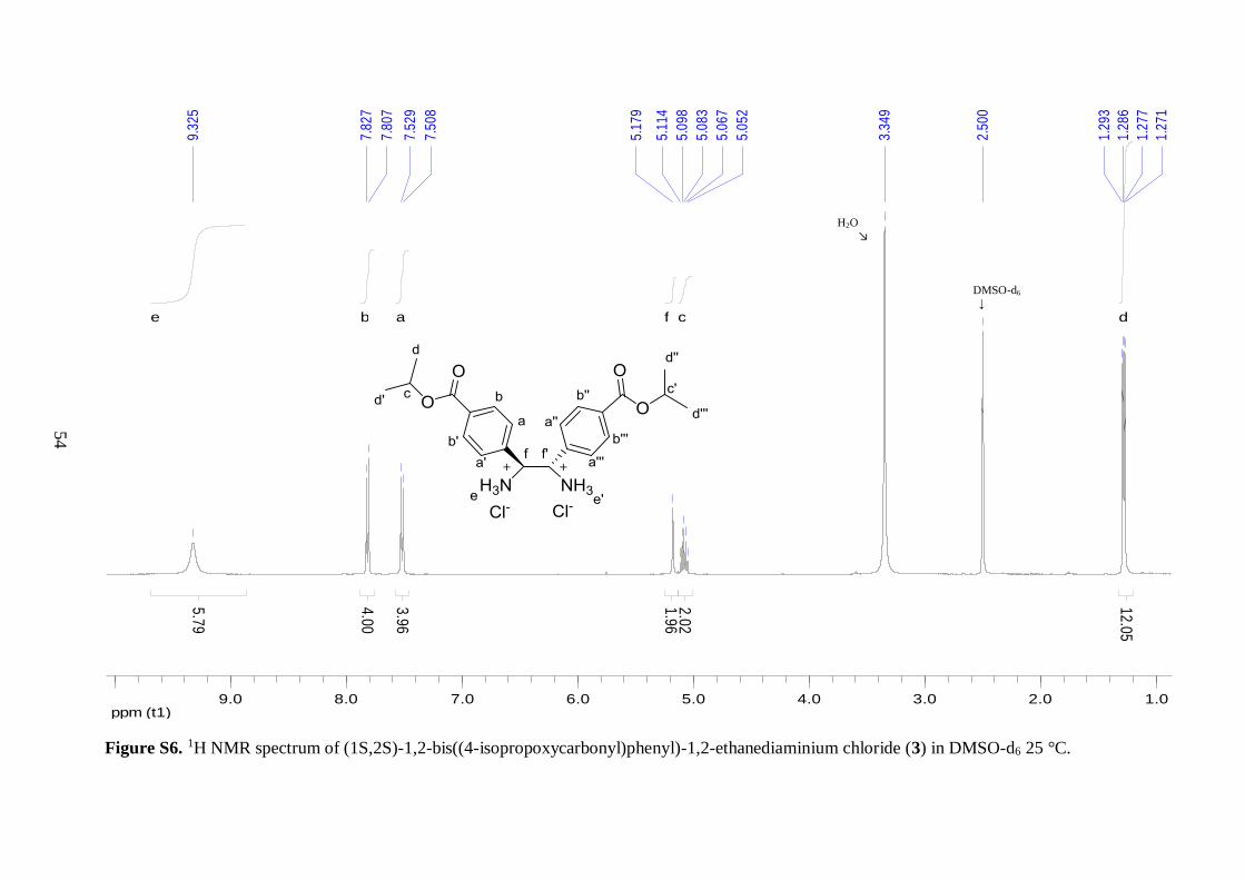
NMR analysis of the hydrochloride salt (3) revealed that the isopropyl ester group
remained intact during the hydrolysis reaction. The two isopropyl peaks, corresponding to
the –CH proton and methyl groups respectively, had analogous chemical shifts and splitting
patterns as observed in the NMR spectra of 2. It was clear from comparison between the 1H
NMR spectra of 2 and 3 that the phenol rings were not present in the latter compound. The
four peaks in the aromatic region of 2 (Figure 4.1) were missing, leaving only the two
doublets from the isopropyl ester substituted aryl rings at 7.82 and 7.52 ppm. This was
further supported by the relatively simple appearance of the aromatic region in the 13C NMR
spectrum of 3. Only four peaks were observed with chemical shifts between 115 and 145
ppm, compared to nine in the same region in the analogous spectrum of 2. Interestingly, the
peak assigned to the –CH protons on the diamine backbone was shifted downfield by 0.46
ppm and the chemical shift was larger than for the isopropyl –CH protons, compared to the 1H NMR spectrum of 2. This observation was reasonable, since protonated amines are more
electron withdrawing than imines, thereby leaving the neighboring –CH proton more
deshielded. The appearance of the broad singlet at 9.33 ppm, which integrated for six protons
and corresponded to the protonated amines, corroborated the successful hydrolysis of 2.
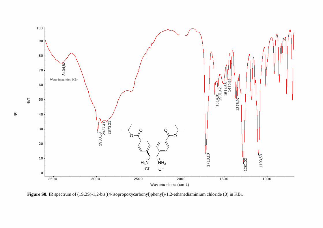
The IR spectrum of 3 further supported the presence of a protonated amine. The sharp
C=N peak observed at 1629 cm-1 in the spectrum of 2 was missing, whereas a broad signal
around 3400 cm-1 was detected, corresponding to N–H stretching vibrations. Furthermore,
the protonated amino groups were assumed to cause the broadening in the 2500-3100 cm-1
region. The three strong C=O and C–O stretching vibrations appeared at similar
wavenumber values as observed for 2, implying that the isopropyl ester groups were
unaffected in the reaction.
These results indicate that the isopropyl ester is highly stable under strongly acidic
reaction conditions and a suitable protecting group for the carboxylic acid functionality.
30
Based on studies by Chin and coworkers, it is hypothesized that the enantiopure (S,S)
diamine hydrochloride salt (3) was isolated because the starting diamine precursor had the
(R,R) configuration (Scheme 2.4).32 However, no further analysis was done in order to test
that hypothesis.
As depicted in Scheme 2.3, the conversion of 3 to its neutral diamine (Scheme 2.3;
4) was accomplished by extraction under basic conditions. The diamine (4) was isolated as
light brown solid in excellent yield (94%). Unlike many amines, 4 is a stable solid material
under ambient conditions and can be stored for relatively long time without any signs of
decomposition.
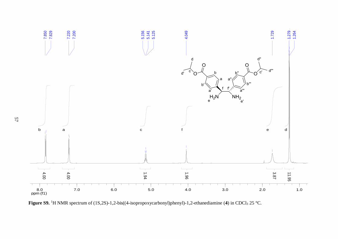
1H NMR analysis of 4 established that 3 was successfully deprotonated. The first
evidence was the replacement of the broad singlet derived from the protonated amino groups
with an upfield shifted broad signal which integrated for four protons and was assigned to
the protons of two neutral amino functional groups. Furthermore, the resonance from the –
CH groups on the diamine backbone was shifted relatively far upfield (1.13 ppm) compared
to that of 3. Even though the spectra of these two compounds were recorded in different
solvents, this observation illustrated that deprotonation of the hydrochloride salt was
successful because protonated diamine is much more electron withdrawing than its neutral
counterpart. Signals from the aryl backbone of 4 were analogous to those observed for 3,
indicating that this part remained unchanged in the neutralization step. Nevertheless, it is
worth to highlight two findings. First, the ortho protons on the aryl rings were shifted 0.3
ppm upfield with respect to their position in the spectrum of 3. Solvent effects were assumed
to be the main cause. Second, the methyl resonance was a doublet instead of two overlapping
doublets, as observed earlier for compounds 2 and 3. This suggests that all the methyl groups
of 4 are chemically equivalent. The reason for this inconsistency still remains unclear.
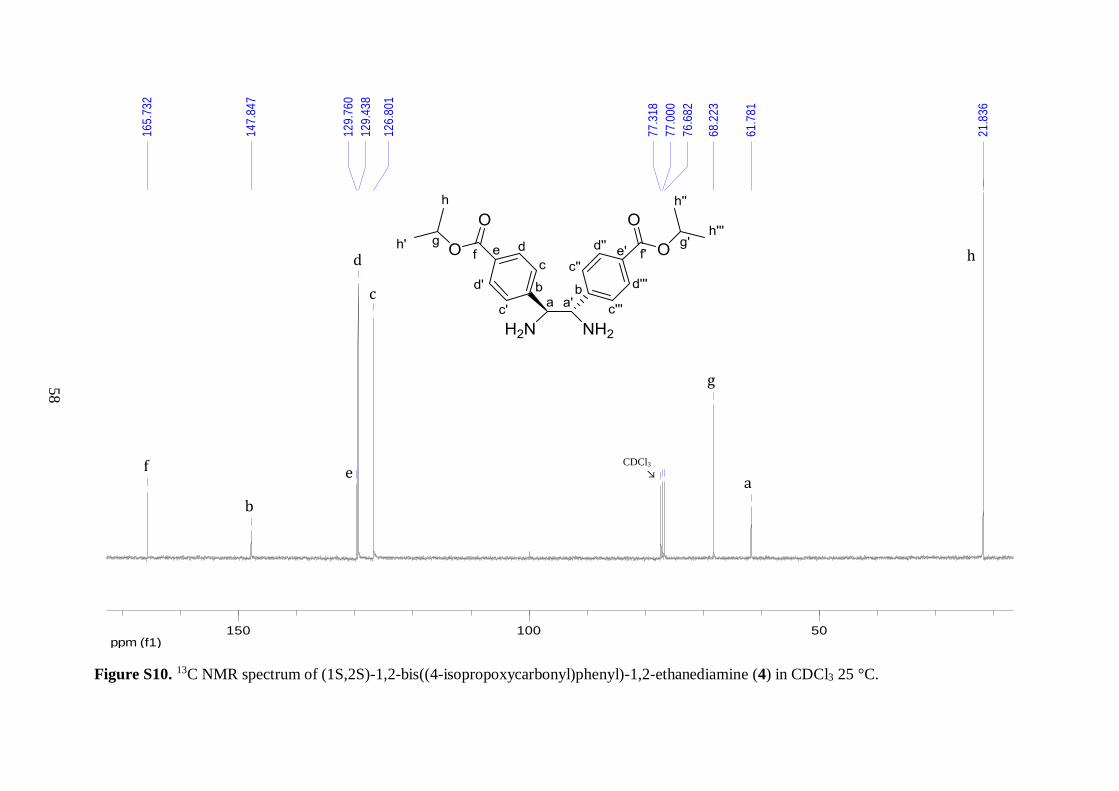
The 13C NMR spectra of compounds 3 and 4 were similar, both displaying eight
resonances as expected. Small shift of peaks was observed, partly due to solvent effects. No
additional information were obtained in order to evaluate whether the deprotonation step
proved successful or not.
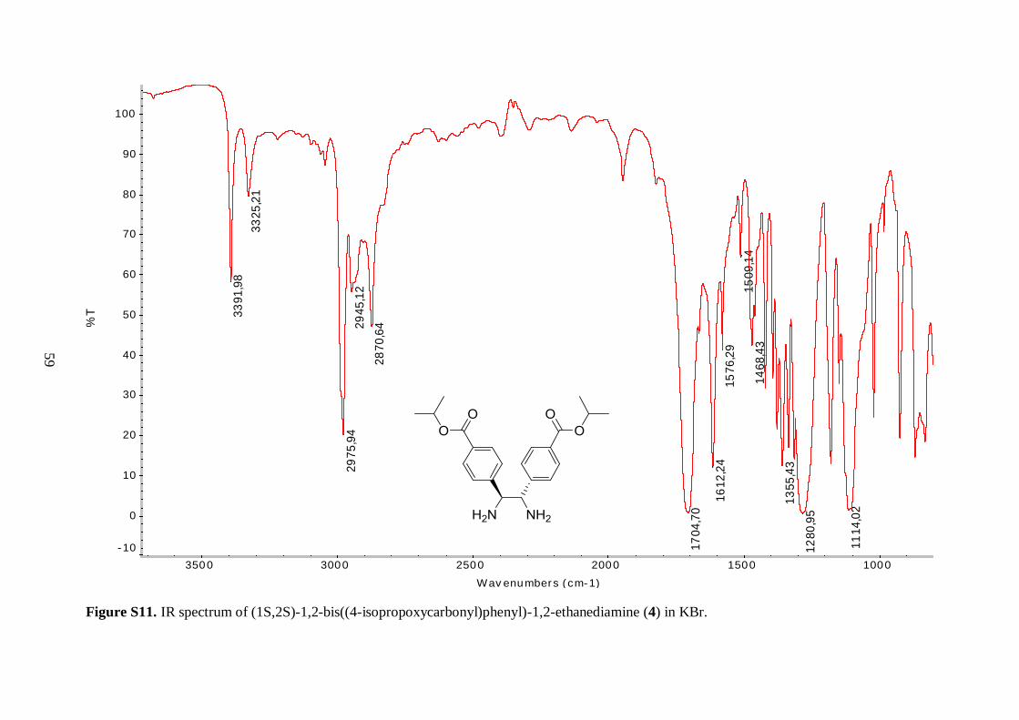
On the other hand, the higher energy region of the IR spectra of these two compounds
was apparently different. In the spectrum of 4, two sharp N–H stretching bands were
observed at 3392 and 3325 cm-1. This was in good agreement with the presence of a primary
amine functionality. The lower energy part of the spectrum got similar appearance as for 3,
further supporting that other functional groups stayed intact during the course of the reaction.
Since 4 is a novel diamine with a wide range of applications in coordination
chemistry, it was desirable to verify its nature by ESI-MS analysis. According to mass
spectral data, the singly protonated molecular ion gave rise to the most intense peak at
385.2122 m/z. These results were parallel with the calculated data of 4, predicting a peak at
384.2049 m/z for the molecular ion.
Having prepared a diamine with the desired functionality, the next step was to use
this compound for the synthesis of salen type ligands.
4.1.4 Schiff base formation
With the aim of preparing salen type ligands from an isopropyl ester functionalized diamine,
two aldehydes with different physical and chemical properties were investigated in the
reaction with 4; unsubstituted salicylaldehyde (liquid at room temperature) and its 3,5-di-
tert-butyl derivative (solid under ambient conditions). Here, it should be mentioned that
condensation of salicylaldehyde with 4 was expected to give diimine 2 (Scheme 2.3). Our
idea was to compare the reactivity of these two aldehydes under the same reaction conditions
31
and these additional synthetic steps were needed to introduce the tert-butyl groups to the aryl
backbone. Moreover, because the preparation of 2 gave a mixture of 1 and 2, and direct
separation of those compounds might cause difficulties, this was envisioned to be a more
favorable way to isolate a clean salen type ligand that could serve as a precursor for the target
metalloligands.
Treatment of 4 with two equivalents of the salicylaldehyde components
(unsubstituted and its 3,5-di-tert-butyl derivative) in dry refluxing ethanol, followed by
quenching with water afforded ligands 5a and 5b (Scheme 2.3), respectively. Interestingly,
a copious amount of the light yellow solid 5a was observed after few hours reaction time,
whereas addition of water was needed to induce the precipitation of the dark yellow solid
5b. This observation illustrates the difference in solubility of the two ligands, caused by the
bulky tert-butyl groups of the former. Compound 5a was isolated in 81% yield, which was
slightly lower than the reported value (95%).28 This is presumably due to less sterically
hindered diamine precursor, which was utilized in the literature reaction. In contrast,
compound 5b was obtained in only 30% yield, which was much lower than expected.
Presumably, not all the compound could be precipitated out due to its high solubility in
ethanol. All attempts to recover more product from the filtrate proved unsuccessful. This
suggests that another solvent and eventually a different synthetic route is needed to increase
the yield of the salen type ligand 5b. Because of the complex structural features of the two
compounds together with their importance in the overall synthesis of the metalloligands, a
combination of various analytical measurements was used to confirm their structures.
Comparison of the 1H and 13C NMR spectra, respectively, of 2 and 5b revealed that
these two compounds were the same, as expected. IR spectroscopy supported this finding,
since bands with identical wavenumbers and appearances were observed and it was further
confirmed by interpreting the mass spectra. The recorded masses of the two diimines were
identical, 593.2646 m/z, corresponding to the singly protonated molecular ion, and their
fragmentation pattern matched as well.
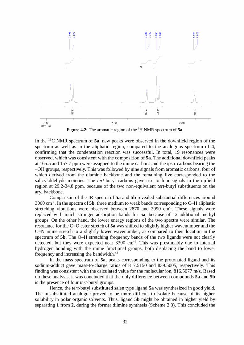
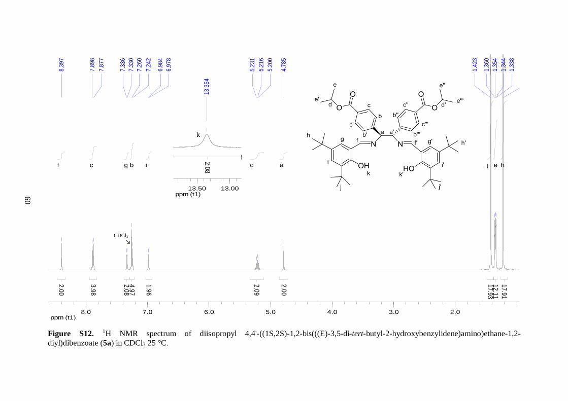
1H NMR analysis of 5a revealed that imine functionality was present, as judged by
the appearance of a singlet at 8.40 ppm. Moreover, absence of the broad signal corresponding
to the amino protons indicated that all the diamine were reacted. The presence of a salen core
was further confirmed by appearance of the broad –OH signal in the downfield region. The
similarities between the spectra of 4 and 5a indicated that the aromatic moieties on the
diamine backbone remained intact during the reaction. Comparison with analogous spectrum
of 5b revealed that there are two main differences. First, the two additional intense singlets
in the spectrum of 5a, at 1.42 and 1.22 ppm (integrated for 18 protons each) coincided with
the three equivalent methyl groups of the tert-butyl substituents. Second, as illustrated in
Figure 4.2, 5a showed less C–H peaks in the aromatic region of the spectrum. This
observation was in good agreement with the presence of tert-butyl substituents on the aryl
backbone, leaving two protons on the benzene rings in meta arrangement with each other.
These protons displayed a small meta-coupling with a coupling constant of 2.4 Hz.
32
Figure 4.2: The aromatic region of the 1H NMR spectrum of 5a.
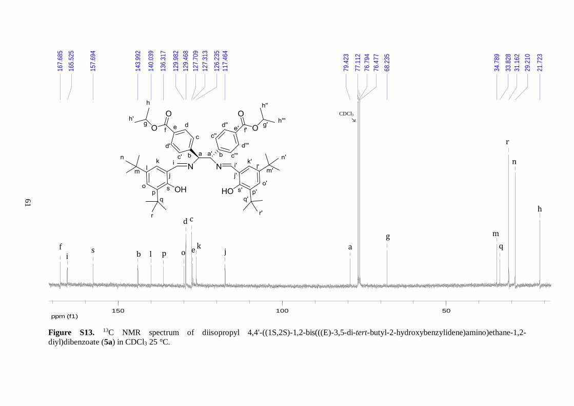
In the 13C NMR spectrum of 5a, new peaks were observed in the downfield region of the
spectrum as well as in the aliphatic region, compared to the analogous spectrum of 4,
confirming that the condensation reaction was successful. In total, 19 resonances were
observed, which was consistent with the composition of 5a. The additional downfield peaks
at 165.5 and 157.7 ppm were assigned to the imine carbons and the ipso-carbons bearing the
–OH groups, respectively. This was followed by nine signals from aromatic carbons, four of
which derived from the diamine backbone and the remaining five corresponded to the
salicylaldehyde moieties. The tert-butyl carbons gave rise to four signals in the upfield
region at 29.2-34.8 ppm, because of the two non-equivalent tert-butyl substituents on the
aryl backbone.
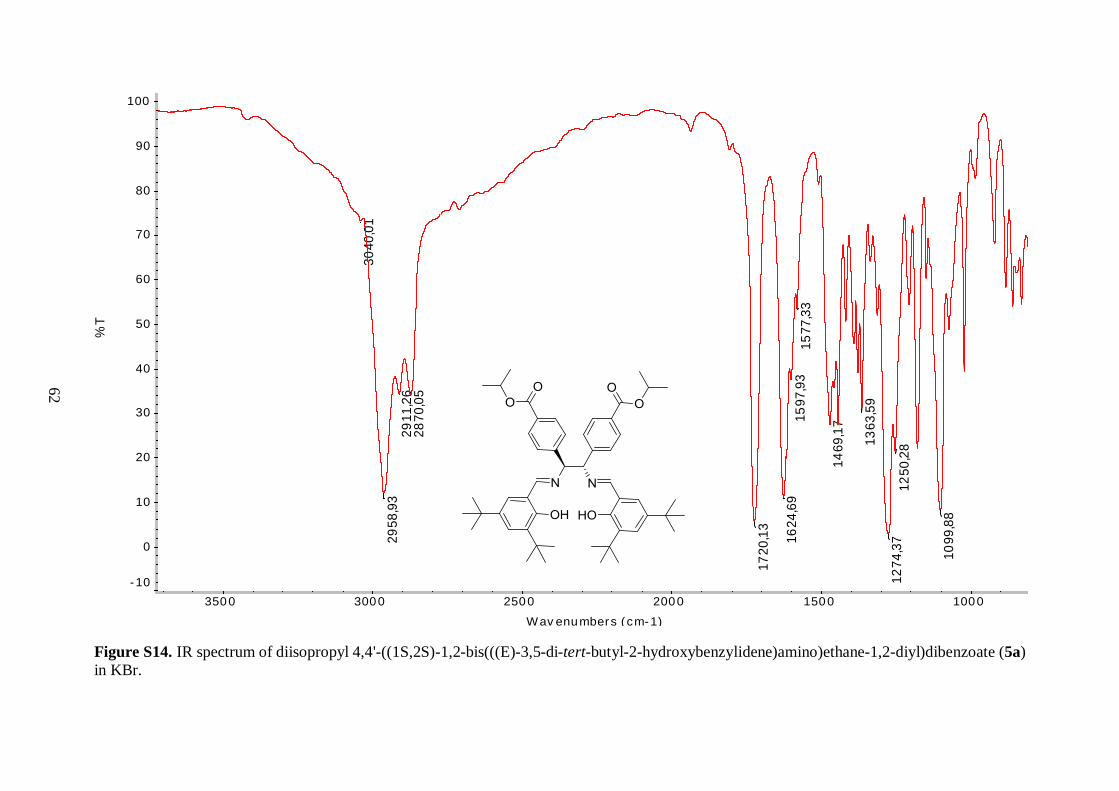
Comparison of the IR spectra of 5a and 5b revealed substantial differences around
3000 cm-1. In the spectra of 5b, three medium to weak bands corresponding to C–H aliphatic
stretching vibrations were observed between 2870 and 2990 cm-1. These signals were
replaced with much stronger adsorption bands for 5a, because of 12 additional methyl
groups. On the other hand, the lower energy regions of the two spectra were similar. The
resonance for the C=O ester stretch of 5a was shifted to slightly higher wavenumber and the
C=N imine stretch to a slightly lower wavenumber, as compared to their location in the
spectrum of 5b. The O–H stretching frequency bands of the two ligands were not clearly
detected, but they were expected near 3300 cm-1. This was presumably due to internal
hydrogen bonding with the imine functional groups, both displacing the band to lower
frequency and increasing the bandwidth.43
In the mass spectrum of 5a, peaks corresponding to the protonated ligand and its
sodium-adduct gave mass-to-charge ratios of 817.5150 and 839.5005, respectively. This
finding was consistent with the calculated value for the molecular ion, 816.5077 m/z. Based
on these analysis, it was concluded that the only difference between compounds 5a and 5b
is the presence of four tert-butyl groups.
Hence, the tert-butyl substituted salen type ligand 5a was synthesized in good yield.
The unsubstituted analogue proved to be more difficult to isolate because of its higher
solubility in polar organic solvents. Thus, ligand 5b might be obtained in higher yield by
separating 1 from 2, during the former diimine synthesis (Scheme 2.3). This concluded the
ppm (t1)7.007.508.00
7.8
98
7.8
77
7.3
36
7.3
30
7.2
60
7.2
42
6.9
84
6.9
78
3.9
8
c
2.0
8
g
1.9
6
i
4.9
7
b
ppm (t1)7.007.508.00
7.8
23
7.8
02
7.2
61
7.2
55
7.1
85
7.1
66
6.9
08
6.9
03
3.9
8
c
2.0
8
g
1.9
6
i
4.9
7
b
33
first part of the project, namely organic synthesis where the desired salen type ligands were
successfully prepared. The next goal towards the preparation of the target metalloligands
involved treatment of the synthesized ligands with metal ions.
4.2 Synthesis and characterization of salen type
metalloligands
4.2.1 The metallation step
In the efforts to introduce catalytically active metal centers to our salen type ligands 5a and
5b, these scaffolds were treated with three different metal precursors: CrCl2, Cu(OAc)2∙H2O
and Co(OAc)2∙4H2O. Because the synthesis of 5a proved to be much more efficient than of
5b, the former ligand was of main interest and only reaction of 5b with CrCl2 was attempted.
As mentioned earlier, two different synthetic procedures were followed to construct the
desired isopropyl ester protected metal-salen complexes. The performed reactions are
outlined in Scheme 2.5. All synthesized complexes were analyzed by IR spectroscopy and
the composition of the complexes derived from 5a was also confirmed by ESI-MS analysis.
The Cr(III) complex 6aI was synthesized in near quantitative yield by treating ligand
5a with CrCl2 in dry refluxing THF, followed by room temperature stirring under normal
atmosphere to allow for the oxidation of Cr(II) to Cr(III). Additionally, an analogous reaction
using ligand 5b afforded the complex 6bI in 90% yield, as displayed in Table 4.1 below.
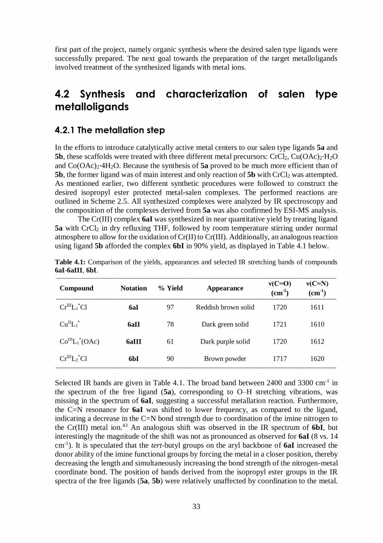
Table 4.1: Comparison of the yields, appearances and selected IR stretching bands of compounds
6aI-6aIII, 6bI.
Compound Notation % Yield Appearance ν(C=O)
(cm-1
)
ν(C=N)
(cm-1
)
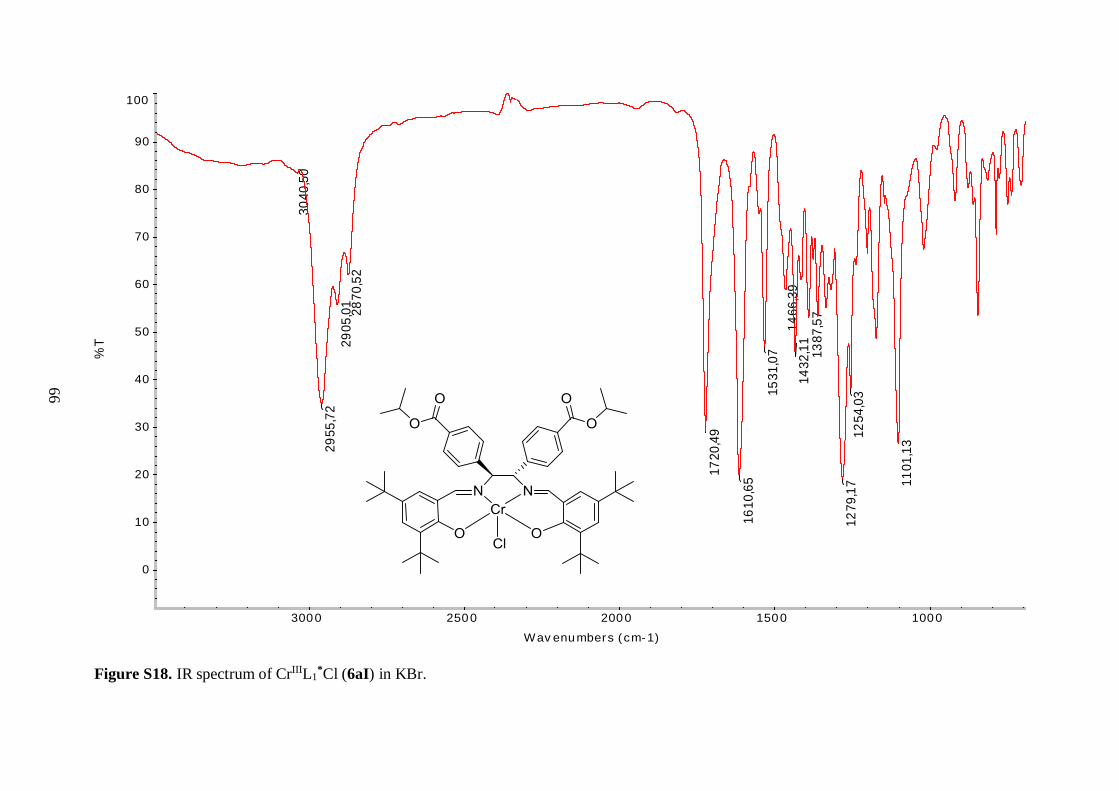
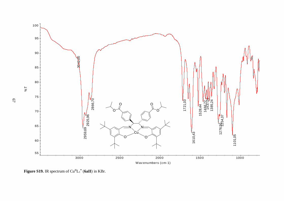
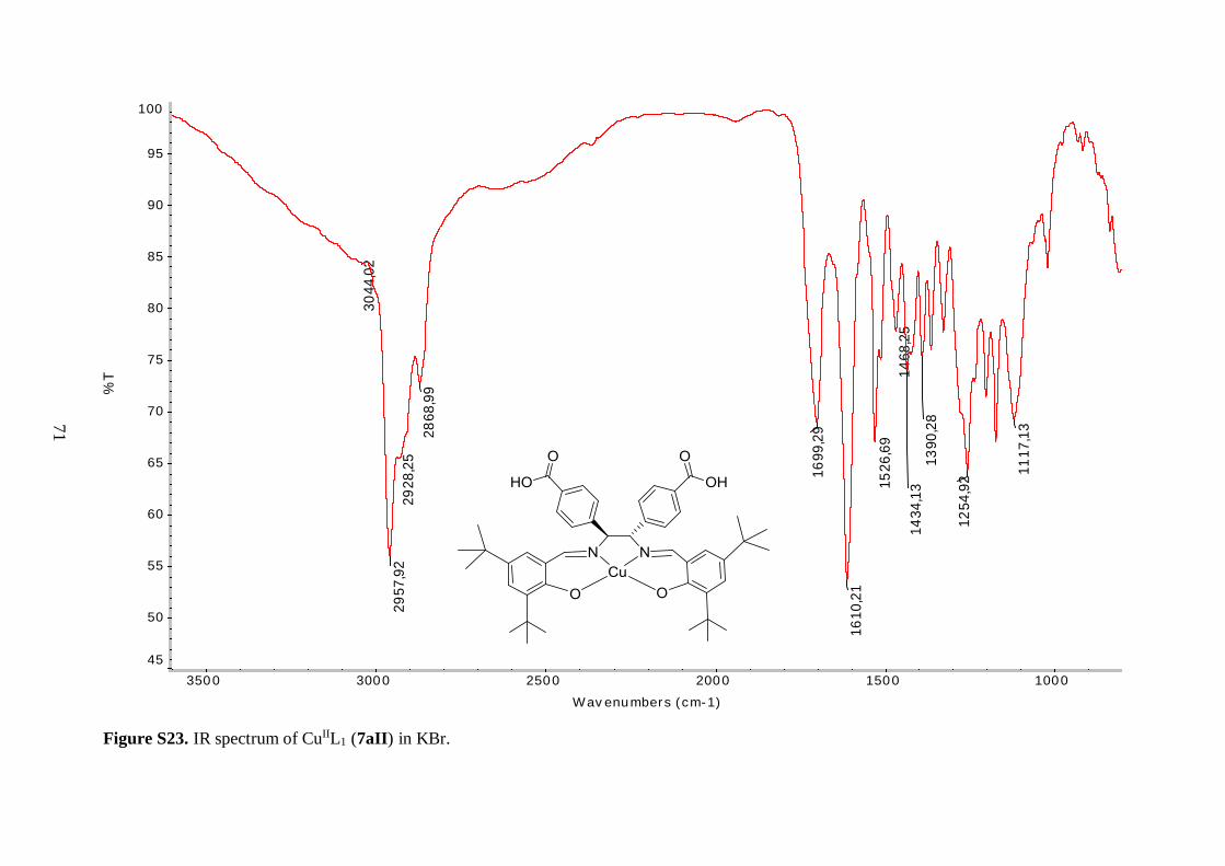
CrIIIL1*Cl 6aI 97 Reddish brown solid 1720 1611
CuIIL1* 6aII 78 Dark green solid 1721 1610
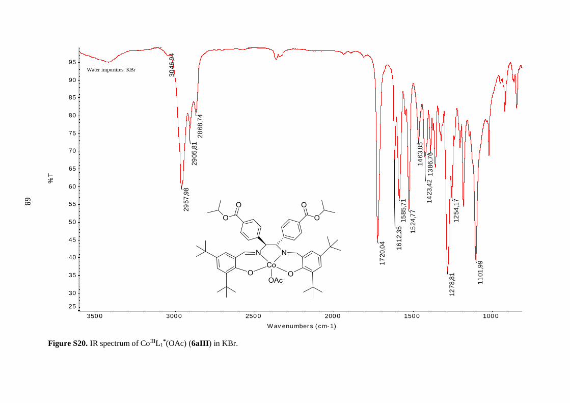
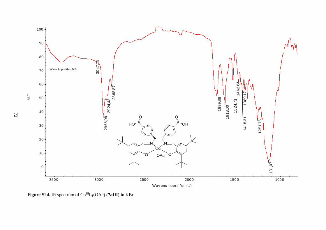
CoIIIL1*(OAc) 6aIII 61 Dark purple solid 1720 1612
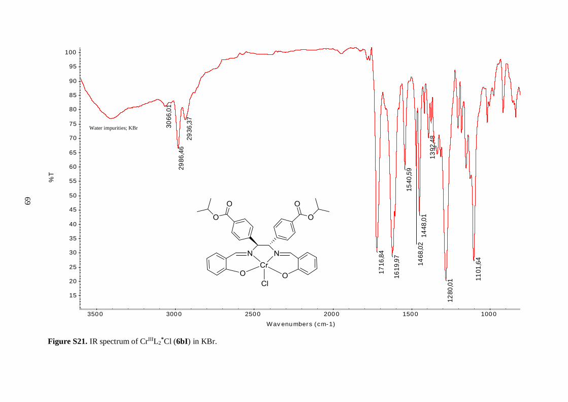
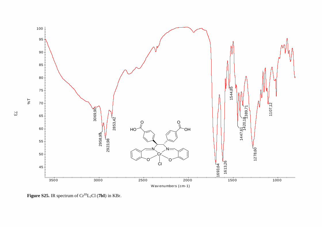
CrIIIL2*Cl 6bI 90 Brown powder 1717 1620
Selected IR bands are given in Table 4.1. The broad band between 2400 and 3300 cm-1 in
the spectrum of the free ligand (5a), corresponding to O–H stretching vibrations, was
missing in the spectrum of 6aI, suggesting a successful metallation reaction. Furthermore,
the C=N resonance for 6aI was shifted to lower frequency, as compared to the ligand,
indicating a decrease in the C=N bond strength due to coordination of the imine nitrogen to
the Cr(III) metal ion.43 An analogous shift was observed in the IR spectrum of 6bI, but
interestingly the magnitude of the shift was not as pronounced as observed for 6aI (8 vs. 14
cm-1). It is speculated that the tert-butyl groups on the aryl backbone of 6aI increased the
donor ability of the imine functional groups by forcing the metal in a closer position, thereby
decreasing the length and simultaneously increasing the bond strength of the nitrogen-metal
coordinate bond. The position of bands derived from the isopropyl ester groups in the IR
spectra of the free ligands (5a, 5b) were relatively unaffected by coordination to the metal.
34
The resonances in the 1400-1600 cm-1 region, which were attributed to aromatic C=C
vibrations, were shifted to lower frequencies for the chromium complexes (6aI, 6bI).
Unfortunately, Cr–O and Cr–N stretching frequencies were too low in energy to be
observed.43 As a consequence, the shift of the C=N stretching vibration to lower energy was
used as a benchmark for the successful synthesis of the metal-salen complexes.
Although IR spectroscopy of 6aI and 6bI strongly suggested that incorporation of
the chromium metal to the salen core of 5a and 5b was successfully accomplished, the mass
spectrum of 6aI was recorded in order to verify its structure. Mass spectral data of the three
tert-butyl salen type complexes (6aI-6aIII) together with their hydrolyzed analogues (7aI-
7aIII) is recorded in Table 4.2. Analysis of 6aI confirmed the presence of a Cr(III) metal
site. The most abundant peak corresponded to the positively charged molecular ion after
losing the coordinating chlorine. Moreover, the chromium isotopic pattern was clearly
detected in the spectrum. Thus, air oxygen proved to be strong enough oxidation agent to
oxidize Cr(II) to Cr(III), as argued in the literature.28 Based on ESI-MS analysis, the metal
center is predicted to adopt a distorted square-based pyramidal geometry with one axial
chlorine completing the coordination sphere.
Table 4.2: ESI-MS analysis of metal-salen complexes 6aI-6aIII and their metalloligand derivatives
7aI-7aIII. M represents the molecule without axial ligands. # Calculated for M.
Compound Notation Calculated
(m/z)
Found
(m/z)
∆m
(m/z) Assignment
CrIIIL1*Cl 6aI 901.4015 866.4321 34.9694 [M-Cl]+
CuIIL1* 6aII 877.4217 900.4109 22.9892 [M+Na]+
CoIIIL1*(OAc) 6aIII 873.4253 # 873.4247 0.0006 M+
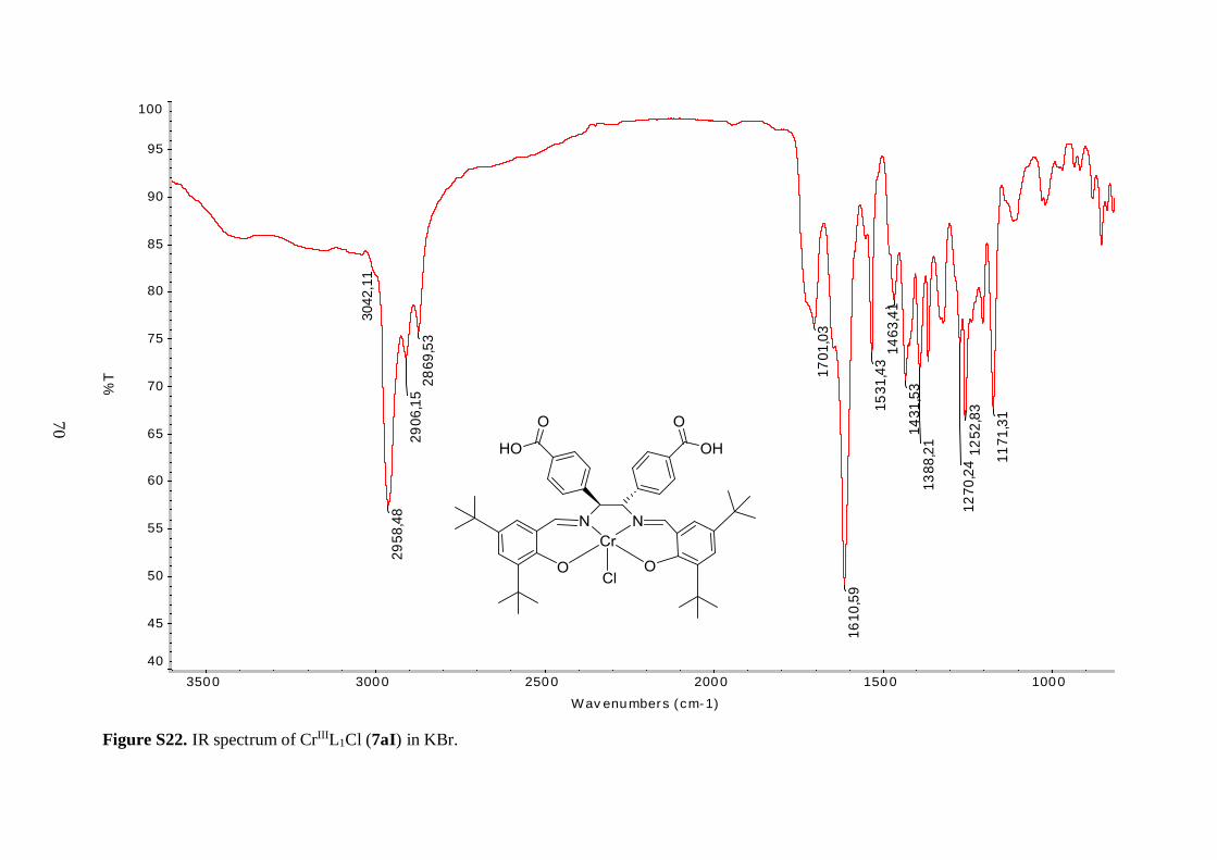
CrIIIL1Cl 7aI 817.3076 782.3382 34.9694 [M-Cl]+
CuIIL1 7aII 793.3278 816.3170 22.9892 [M+Na]+
CoIIIL1(OAc) 7aIII 789.3314 # 789.3308 0.0006 M+
An alternative procedure was followed to prepare the copper and cobalt analogues of 6aI.
Treatment of 5a with Cu(II) and Co(II) acetates, respectively, in refluxing ethanol or a
methanol/ethanol mixture, afforded compounds 6aII and 6aIII as solid materials. The Cu(II)
complex 6aII was isolated in moderate yield, however the yield of the cobalt complex 6aIII
was only 61%, as illustrated in Table 4.1. The low yield of the latter can be partly explained
by some difficulties that were faced while work-up.
The IR spectra of 6aII and 6aIII revealed similar features as observed for 6aI. The
C=N stretching vibration was shifted to lower frequency, as compared to the free ligand 5a,
indicating coordination of the imine nitrogen to the metal ions. Again, the vibrational
frequencies corresponding to the isopropyl ester groups were unaffected by incorporation of
the metal centers. The three tert-butyl salen complexes (6aI-6aIII) exhibited C=O ester
stretching bands with the same frequency (Table 4.1), further demonstrating that the ester
moieties were not affected by the nature of the coordinated metal. Surprisingly, the same
held true for the imine functionality, as judged by the similar C=N stretching vibrational
frequencies of these compounds (Table 4.1). These findings suggest that the strength of the
35
nitrogen-metal coordinate bonds is approximately the same for all three complexes. The
metal-oxygen and metal-nitrogen-stretching frequencies were also not observed in the
spectra of 6aII and 6aIII. This was reasonable, since according to the literature, Cu–O
stretching bands are for example expected in the range 304-476 cm-1.44
Mass spectral analysis of 6aII and 6aIII further supported that the salen type
complexes were successfully prepared (Table 4.2). Moreover, these data were employed to
identify oxidation states of the metal centers. Cu(II) metal site is present in 6aII because the
neutral compound picked up Na+ from the solvent matrix in order to become positively
charged, allowing for its measurement since the mass spectrometer was employed in positive
ion mode. On the other hand, analysis of 6aIII suggested that the cobalt ion is in +3 oxidation
state since the molecular ion without any external ligands was positively charged. It is
hypothesized that an axial acetate anion from the reaction medium completes the five-
coordinate sphere of the Co(III) ion in 6aIII. Yet, this was not further explored. The acetate
anion was assumed to fly easily off in the mass spectrometer, just as the axial chlorine ligand
in 6aI. In addition, the isotopic patterns observed in the mass spectra of 6aII and 6aIII
matched the characteristic isotopic envelopes of copper and cobalt, respectively.
Since both Cr(III) (d3) and Cu(II) (d9) are paramagnetic metal centers and Co(III)
(d6) can be either para- or diamagnetic, depending on the ligand field strength and geometry,
it was of great interest to prepare diamagnetic salen complexes, analogous to compounds
6aI-6aIII. These compounds will allow for general NMR measurements, both to explore
whether the 1H and 13C NMR spectra of 5a change upon metallation and to provide further
information about the outcome of the ester deprotection step. With this in mind, 5a was
treated with Zn(II) acetate in an analogous reaction as carried out to prepare compounds 6aII
and 6aIII. Unfortunately, NMR and IR analysis revealed that complexation was
unsuccessful, only the unreacted ligand was collected. This may be due to the strong
coordination of the acetate ions to Zn(II) metal centers, thereby interfering with its
incorporation to the salen type ligand. Therefore, a metal precursor with less basic nitrate
anions was attempted. Again the reaction proved unsuccessful, even though the reaction time
was extended and tetrafluoroborate (BF4-) anions were used to enhance the reactivity of the
Zn(II) ions. As a result, it was more difficult than expected to introduce a Zn(II) metal center
to the salen core of 5a.
After accomplishing the synthesis of complexes 6aI-6aIII and 6bI only hydrolysis
of the isopropyl ester groups remained in order to conclude the second part of this project
and acquire the target metalloligands (Scheme 2.1).
4.2.2 The deprotection step
The isopropyl ester groups proved to be stable under all reaction conditions up to this stage.
However, a crucial function of a protecting group involves its facile removal, without
altering other present functionalities. Hence, this last step was a key step in the overall
synthesis of the target metalloligand unit (Scheme 2.1).
As a starting point for the base induced hydrolysis reaction, the prepared ester
complexes (6aI-6aIII, 6bI) were refluxed in an equivolume mixture of 10% (w/v) aqueous
KOH solution and EtOH (Scheme 2.5). These reactions were monitored by TLC analysis,
since the ester functionalized complexes moved easily in polar solvent mixtures
(10:90 methanol/dichloromethane) in contrast to their carboxylic acid analogues. Extraction
under acidic conditions afforded compounds 7aI-7aIII, 7bI as solid materials. A
combination of IR and ESI-MS analysis was used to confirm the structures of the prepared
metalloligands.
36
The hydrolysis of 6aI proceeded well, all the starting material was consumed after
5 h reaction time and 7aI was isolated in 89% yield as reddish brown solid with a brighter
color than its ester precursor. However, excess amount of base was needed to induce the
hydrolysis of 6aII and 6aIII. For the former, additional amount of base was added after
24 h reflux, because at that time TLC analysis indicated that the reaction was still not
completed. Yet, the Cu(II) metalloligand 7aII was collected in near quantitative yield as
dark green solid, the same color as its precursor. Hydrolysis of 6aIII could not be driven to
completion, even though various attempts were made. As a result, 7aIII was isolated in
relatively low yield, approximately 50%. To begin with, the hydrolysis of 6bI proceeded
well but an insoluble slurry material was generated during work-up. Consequently, the yield
of the light brown compound 7bI was only 14%.
Selected vibrational bands for the isopropyl ester protected salen complexes (6aI-
6aIII, 6bI) and their hydrolyzed products (7aI-7aIII, 7bI) are provided in Table 4.3. The
most obvious difference in the IR spectra of these two classes of compounds, is the shift of
C=O vibrational modes of the products to lower wavenumbers by 19-23 cm-1. These findings
indicated that ester functional groups were replaced with carboxylic acids. Furthermore,
some differences were observed in the range 1100-1300 cm-1. The strongest bands in that
region corresponded to C–O stretching vibrations. In the IR spectrum of 6aI, the strongest
bands were located at 1101 and 1279 cm-1, and a less intense peak at 1254 cm-1 was observed.
However, in the spectrum of 7aI the intensity of the peak around 1254 cm-1 was increased,
while the other two were diminished in intensity. Comparison of the spectra of copper
complexes 6aII and 7aII, and cobalt complexes 6aIII and 7aIII, respectively, revealed
similar trends. These observations strongly suggested that the chemical environment around
the C–O functionality changed during the course of the reaction, coinciding with the
replacement of an isopropyl group with a proton.
Table 4.3: Comparison of selected IR stretching bands of compounds 6aI-6aIII, 6bI and their hydrolyzed analogues 7aI-7aIII, 7bI.
Compound Notation ν(C=O)
(cm-1
)
ν(C=N)
(cm-1
)
ν(C–O)
(cm-1
)
CrIIIL1*Cl 6aI 1720 1611 1279, 1254, 1101
CuIIL1* 6aII 1721 1610 1277, 1254, 1101
CoIIIL1*(OAc) 6aIII 1720 1612 1279, 1254, 1102
CrIIIL2*Cl 6bI 1717 1620 1280, 1102
CrIIIL1Cl 7aI 1701 1611 1270, 1253, 1171
CuIIL1 7aII 1699 1610 1255, 1117
CoIIIL1(OAc) 7aIII 1700 1613 1252, 1131
CrIIIL2Cl 7bI 1694 1613 1279, 1107
The broadness between 2400 and 3500 cm-1 in the spectra of 7aI-7aIII, attributed to O–H
stretching vibrations, further supported this presumption. In addition, since no frequency
shift was observed for the C=N stretching mode, it could be assumed that the salen core
remained intact during the synthesis of 7aI-7aIII. On the contrary, the C=N resonance band
37
of 7bI was shifted to slightly lower frequency compared to 6bI. Moreover, the changes in
the C–O stretching region were not as pronounced for 7bI as for the other three products.
The reason for this inconsistency between compounds still remains a mystery.
ESI-MS measurements of 7aI-7aIII revealed that the carboxylic acid functionalized
metalloligands were successfully synthesized. The obtained results, together with
assignments of the most abundant peaks are provided in Table 4.2. The recorded mass
difference between the ester functionalized complex and its hydrolyzed product was the
same (84.0939 m/z) for all three pairs. This coincided well with the replacement of two
isopropyl esters with hydroxyl groups. It is speculated that metalloligands 7aI-7aIII are
relatively stable species because the intact carboxylic acid moieties were detected in the
mass spectra of all three compounds. Moreover, the characteristic isotopic patterns of Cr, Cu
and Co were clearly present in the mass spectra of the products, thereby further supporting
that the secondary functional site on the salen scaffolds remained intact during the
deprotection reaction. In addition, there was no sign of unreacted ester complexes 6aI-6aIII
in the spectra of their hydrolyzed analogues 7aI-7aIII, suggesting that the isolated products
were pure.
It should be mentioned, that because of the basic reaction conditions, it is likely that
the axial chlorine and acetate ligands of 6aI and 6aIII were replaced by hydroxyl anions in
the structures of 7aI and 7aIII. However, additional analytical techniques are needed to
elucidate the exact nature of the fifth ligand in these compounds.
Because the prepared metalloligands (7aI-7aIII, 7bI) and their ester precursors (6aI-
6aIII, 6bI) are novel compounds, it was of great desire to obtain crystal structures of these
materials. With that data in hand a better insight into the configuration on the diamine
backbone can for example be gained, together with information about the coordination
spheres of the metal ions. In order to grow crystals suitable for X-ray crystallography, several
crystallization methods were attempted, including slow evaporation of a solvent, vapor
diffusion and layering techniques. Most effort was put into growing crystals of the chromium
complexes 6aI and 7aI, because the former was synthesized in higher yield than the other
ester complexes and its subsequent hydrolysis proceeded well, affording 7aI in good yield.
As a first approach, these compounds were dissolved in various organic solvents and
the solvent was slowly evaporated. Different concentrations of the complexes solutions were
utilized, as well as binary and ternary solvent mixtures. All the attempts to grow single
crystals with this technique proved unsuccessful, either no precipitate or powders were
observed. All the prepared compounds (Table 4.3) were soluble in most of the common
organic solvents except hexane. Therefore, hexane was the only solvent that could serve the
role as a cosolvent for layering and vapor diffusion crystallization methods. By utilizing
these two methods, the most promising results were obtained when hexane was slowly
diffused into a 7% (w/v) chloroform/methanol (3:1) or dichloromethane/methanol (3:1)
solutions of 7aI. Unfortunately, single crystals were not formed, rather fibrous crystalline
networks were isolated. It is envisioned that the bulky tert-butyl substituents on the aryl
backbone of compounds 6aI and 7aI interfered with the crystal growth in two concurrent
ways. First of all, their presence enhances the solubility of the complexes in organic solvents,
thereby limiting the number of solvents and crystallization techniques available to grow
proper crystals. Second, because of their large size the molecules tend to stick together,
which makes the formation of fibrous moieties more likely than single crystals.
Although the presence of tert-butyl groups on the aryl backbone increased the
stability of the metalloligands and facilitated their formation, they caused problems for the
crystal growth of these compounds. So far, all the crystallization setups of the complexes
listed in Table 4.3 have been unsuccessful.
38
The second part of this thesis project was successfully accomplished. However, the
synthesis of the Cu(II)-salen type metalloligand 7aII and the Co(III)-salen type metallo-
ligand 7aIII, as well as the derivatives of ligand 5b could have proceeded better.
Furthermore, the synthetic route outlined in Scheme 2.2 was indeed an ideal way to prepare
metalloligands with the desired functionalities and the next goal was to use these bifunctional
ligands to construct MOFs for catalytic applications.
4.3 Synthesis of MOFs
For all the attempted synthesis of MOFs, only metalloligand 7aI was utilized as the ligand
component because of its ease of preparation, compared to the other metalloligands. As a
first trial for the formation of crystalline frameworks, 7aI was dissolved in ethanol to give
2.5% (w/v) solutions and layered with 6 mM aqueous solutions of four different metal salts,
namely Ca(NO3)2∙4H2O, CaCl2∙2H2O, Cu(NO3)2∙3H2O and Zn(NO3)2∙6H2O, respectively.
In all cases an orange gel-like precipitate formed after the mixtures were allowed to stand at
room temperature for several days. These observations apparently indicated that water was
not a proper solvent for this task.
Next, DMF was utilized as a solvent for both structural components. The
metalloligand 7aI and the metal salts LaCl3∙7H2O, Zn(NO3)2∙6H2O and Cu(NO3)2∙3H2O,
respectively, were mixed in equimolar ratios before adding DMF. Furthermore, the resulting
reaction mixtures were heated for a different amount of time, as illustrated in Table 4.4.
Table 4.4: Attempted synthesis of MOFs, constructed from 7aI and different metal salts in 3 mL of
DMF upon heating.
Experiment 7aI
(mmol) Metal salt
Temperature
(°C)
Reaction
time (h) Observation
1 0.03 LaCl3∙7H2O 80 1 No precipitate
2 0.03 Zn(NO3)2∙6H2O 100 12 No precipitate
3 0.03 Cu(NO3)2∙3H2O 100 18 Reddish orange
crystalline solid
As emphasized in Table 4.4, crystalline material was observed when 7aI was treated with
the Cu(II) metal salt under the previously described reaction conditions. In contrast, no
precipitate was observed when La(III) and Zn(II) metal precursors were utilized under
similar conditions. Additionally, light orange flakes were observed floating in the Cu(II)-
metalloligand solution. These crystals were insoluble in methanol and slightly soluble in
DMF, indicating that a coordination polymer was formed. Unfortunately, the crystals were
not single, rather forming fibrous networks. Still, these findings suggested that Cu(II) metal
ions were ideal candidates for the preparation of MOFs with metalloligand 7aI. Thus, we
have chosen Cu(NO3)2∙3H2O as the secondary metal component. Furthermore, these
experiments indicate that higher temperature synthesis is more effective than ambient
temperature mixing for the structural units utilized in this work.
In order to analyze the effects of different solvents as auxiliary agents for MOFs
synthesis, a Cu(II)-metalloligand stock solution (10% (w/v) with respect to 7aI) in DMF was
prepared by refluxing the reaction mixture for 3 days. Subsequently, a second solvent was
39
added to the resulting dark red homogeneous solution. The types of external solvents used,
together with the main observations made are summarized in Table 4.5.
Table 4.5: Attempted synthesis of MOFs, addition of auxiliary solvents to a Cu(II)-metalloligand
7aI stock solution in DMF.
Experiment Stock solution
(mL)
Solvent
(mL)
Reaction
conditions Observation
1 2.0 Hexane / 4.0 rt layering No precipitate
2 2.0 Diethyl ether / 4.0 rt layering No precipitate
3 2.0 Acetonitrile / 4.0 rt layering No precipitate
4 2.0 Methanol / 4.5 rt layering Dark red powder
precipitate
5 2.0 Ethanol / 4.0 rt layering No precipitate
6 2.0 Acetone / 4.0 rt layering No precipitate
7 2.0 THF / 4.0 rt layering No precipitate
8 2.0 Toluene / 4.0 rt layering No precipitate
The only detectible change was observed when methanol was added as a second solvent, as
stated in Table 4.5. However, only powder precipitate was collected, indicating that all these
experiments proved to be unsuccessful to grow crystalline materials. Interestingly, a
precipitate was obtained when tert-butyl ether was tried as a solvent. The resulting dark
brown precipitate was soluble in methanol, verifying that a coordination polymer was not
formed and eventually the metalloligand precipitated out.
To explore whether a ternary solvent mixture was more effective for the preparation
of MOFs, compared to binary mixtures, chloroform and hexane (1:2) were layered to a
homogeneous Cu(II)-metalloligand solution in DMA (prepared in a similar way as the DMF
stock solution described earlier). Non-crystalline orange plates were observed after a week
at room temperature, suggesting that a ternary solvent system might be a favorable route
towards the desired crystalline framework. In order to achieve this, various parameters such
as the concentration of the metalloligand solution and types of solvents have to be optimized.
Therefore, regarding the time available for this project, it was decided to focus on
synthesizing MOFs in a single solvent system and binary mixtures.
The effects of varying the concentration of the metalloligand and the crystallization
conditions were examined in DMF. For all attempts 7aI was treated with one equivalent of
Cu(NO3)2∙3H2O and the resulting mixtures were heated at 120 °C for 12 h in sealed vials.
Afterwards, different conditions were tried to crystallize the assumed network out, as further
described in Table 4.6.
40
Table 4.6: Attempted synthesis of MOFs by varying the concentration of 7aI in DMF and utilizing
different crystallization conditions.
Experiment 7aI
(mg)
7aI
(% w/v)
Cu(II)
solvent Method Observation
1 9.1 4.6 DMF rt slow
evaporation
Dark red precipitate,
formed gel-like matter
after 3 weeks
2 13.1 6.6 DMF Fridge 2
weeks, then rt Dark red crystalline
plates in the solution
3 19.8 9.9 DMF Freezer 2
weeks, then rt
Orange plates floating in
solution, reddish orange
crystals on the sides
4 16.4 8.2 Methanol Freezer 2
weeks, then rt
Dark red crystalline
plates in the solution,
formed gel-like matter
after 3 weeks
Up to this stage the Cu(II)-metalloligand solutions were prepared in different ways, both at
ambient conditions and with higher temperature procedures, but only slow evaporation at
room temperature was tried as an after-synthesis crystallization technique. Since those trials
gave precipitate or non-single crystals it was speculated that slowing down the crystallization
process might facilitate the formation of suitable crystals for diffraction analysis.
Slow evaporation of 4.6% (w/v) metalloligand solution in DMF in the presence of a
molar equivalent of Cu(II) salt afforded dark red precipitate, which interestingly formed gel-
like matter after standing for several weeks (Table 4.6; Experiment 1). By increasing the
concentration of the metalloligand and leaving the solution in the fridge, crystalline plates
were obtained (Table 4.6; Experiment 2). Finally, after increasing the concentration of 7aI
to 9.9% (w/v) and further slowing down the crystallization process, both plates and crystals
were observed (Table 4.6; Experiment 3). These findings demonstrate that higher
concentration of 7aI in DMF and additional cooling processes are more favorable routes
towards the desired crystalline framework. For comparison, a single experiment using
methanol as a solvent for the Cu(II) salt was carried out. Analogous crystalline plates as
earlier observed in DMF were obtained, but with darker color. Moreover, a gel-like material
formed again upon standing at room temperature for several weeks. The reason for this gel
formation still remains unclear.
In order to determine whether a coordination polymer was formed or not, the
solubility of the crystalline components was examined in methanol and DMF. These
materials turned out to be completely insoluble in methanol and slightly soluble in DMF,
strongly suggesting the formation of coordination polymers. Although crystalline materials
were obtained with the above mentioned procedures, none of them gave single crystals that
allowed for structural determination of the prepared compounds. As a consequence, it was
hypothesized that harsher synthetic conditions were needed to form the MOF.
To test this hypothesis, three attempts were made to synthesize MOFs via
solvothermal procedures. Detailed description of the amount of metalloligand and metal salt
used, the solvent and exact reaction conditions are provided in Table 4.7 below. The main
observations are illuminated there as well.
41
Table 4.7: Attempted solvothermal synthesis of MOFs, constructed from 7aI and Cu(NO3)2∙3H2O.
Experiment
7aI
(mmol /
% w/v)
Cu(II)
(mmol)
Solvent
(mL)
Ampoule
(cm)
Reaction
conditions
(°C / h)
Observation
1 0.06 / 13.9 0.12 DMA / 3.5 15.5 80 / 24
120 / 16
Colloidal
material
2 0.03 / 41.7 0.15 DMA / 1.2 6.0 140 / 24 Dark red crystals
The formamide-functionalized solvents DMA and DMF were considered good candidates
for this method, allowing for high temperature conditions. When a 13.9% (w/v) solution of
7aI in DMA in the presence of two equivalents of Cu(II) salt was heated to 80 °C, an orange
colloidal material was observed after 24 h (Table 4.7; Experiment 1). Further heating to
120 °C for 16 h afforded more solid material with identical appearance. Based on these
observations, it was inferred that the concentration of the metalloligand was too low.
Moreover, it was speculated that higher temperature and pressure were needed to form the
crystalline framework. Therefore, more concentrated solutions of 7aI were prepared and
shorter ampoules together with higher reaction temperature were used in the latter two
experiments (Table 4.7; Experiments 2-3). With the aim of finding the appropriate reaction
mixture and conditions, the amount of the Cu(II) salt was varied and both DMA and DMF
solvents were used, respectively. Unfortunately, the DMF solution was completely dried up
after heating for 24 h, presumably because the ampoule was not properly sealed. On the other
hand, small dark red crystals were observed in the DMA solution that remained. The
solubility test indicated that a coordination polymer was formed. The obtained crystals were
not suitable for structural analysis, both because they were too small and owing to the fact
that they formed colonies rather than staying single. Still, these findings support that higher
ligand concentration facilitates the construction of MOFs. Besides, the temperature and
pressure were shown to play a crucial role and it is probable that even higher temperature
and longer reaction time would have provided crystals with the desired properties.
So far, all attempts to grow crystals suitable for X-ray crystallography have proven
unsuccessful. Although that is a crucial part of MOFs synthesis, which provides evidence
about the exact nature and characteristics of the frameworks, the catalytic activity of the
prepared coordination polymers could still be explored. The most suitable candidates for this
task were the last mentioned crystals from solvothermal synthesis in DMA (Table 4.7;
Experiment 2), the reddish orange material obtained when a DMF solution was kept in the
freezer (Table 4.6; Experiment 3) and the first evident crystalline solid that was obtained
(Table 4.4; Experiment 3). With these compounds in hand, the third part of the thesis project
was concluded. For the remaining part, i.e. the catalytic section, it was of great desire to
investigate the catalytic activity of these materials towards the coupling reaction of CO2 and
epoxides, and compare to the performance of their homogeneous metalloligand building
blocks.
42
4.4 Catalytic investigation of metalloligands and MOFs
With the aim of evaluating the catalytic performance of the synthesized metalloligands and
coordination polymers in the previously mentioned CO2 fixation reaction, they were treated
with propylene oxide and styrene oxide respectively, in the presence of CO2 under different
reaction conditions. Homogeneous catalysis with metalloligand 7aI was attempted first
because it was envisioned that the possible catalytic activity of the synthesized coordination
polymers was mainly introduced by the salen type metalloligand struts. Given these points,
the aim was set on to establish the catalytic activity of 7aI before proceeding to
heterogeneous catalysis with the prepared coordination polymers.
First, 7aI was treated with propylene oxide under mild reaction conditions in an
attempt to convert atmospheric CO2 to propylene carbonate. A balloon with CO2 was utilized
as a CO2 source. After 12 h reaction at both room temperature and 40 °C, all the solution
was evaporated, indicating that the setup was not proper. Analysis of the crude residue
suggested that no reaction occurred, only a mixture of the starting epoxide and
uninterpretable impurities were collected, as judged by 1H NMR spectroscopy.
On the basis of these observations, it was clear that a better experimental setup was
needed to carry out the CO2 fixation reaction in an efficient way. To fulfill these
requirements, an alternative equipment was used which allowed for higher pressure CO2
reactions. The catalytic activity of 7aI under these harsher conditions was tested. One
equivalent of 4-dimethylaminopyridine (with respect to 7aI) cocatalyst was used for all
trials. Summary of the reaction conditions and main results of the performed experiments is
presented in Table 4.8.
Table 4.8: Attempted homogeneous catalysis with 7aI at 40 psi CO2 pressure in the cycloaddition reaction of CO2 to epoxides to form cyclic carbonates. # Catalyst was activated prior to use.
Experiment 7aI
(mmol)
Substrate
(mmol)
Solvent
(mL)
Reaction
conditions
(°C / h)
Observation
1 0.012 Styrene oxide
/ 20.0 CH2Cl2 / 1.7 25 / 2
Precipitate; No conversion
2 0.038 # Styrene oxide
/ 60.0 CHCl3 / 0.5 25 / 6
Homogeneous;
No conversion
3 0.038 # Propylene oxide
/ 57.2 CHCl3 / 0.5 25 / 4
Homogeneous;
No conversion
Surprisingly, when styrene oxide was treated with CO2 at 40 psi pressure for 2 h at room
temperature, in the presence of 7aI, an orange precipitate and dark colored particles were
observed (Table 4.8; Experiment 1). However, GC and GC-MS analysis of the filtrate
confirmed that CO2 conversion did not happen, only peaks derived from the starting epoxide
were detected. Yet, these observations indicated that the homogeneity of the metalloligand
(7aI) was lost after treatment with CO2. In contrast, repeating the experiment for a longer
reaction time and activating the metalloligand (7aI) by vacuum heat-treatment prior to the
reaction, afforded no detectible change in the reaction mixture (Table 4.8; Experiment 2).
Again, no cyclic carbonate was produced, as judged by GC measurements. The reason for
this inconsistency still remains a mystery and further investigation in the nature of this
reaction is needed.
43
Based on earlier findings, propylene oxide was considered to be a more favorable
substrate than styrene oxide because of its greater reactivity. Nevertheless, no conversion
took place when propylene oxide was treated with CO2 under previous reaction conditions,
even after 4 h reaction time (Table 4.8; Experiment 3). This was verified by GC analysis of
the reaction mixture, after removal of 7aI by column chromatography. Since propylene
oxide is very volatile it moved with the solvent, giving rise to an intense signal at 1.1 min.
No other peaks were observed, but based on measurements of the neat carbonate under the
same experimental conditions, the product was expected to have a retention time of 6.7 min.
These results were disappointing, considering that an analogous Cr(III) salen complex
exhibits 100% conversion after 1.5 h reaction time under similar reaction conditions. This
may be due to slightly higher CO2 pressure (50 psi) and higher temperature (75 °C) used in
the reported reaction.28 This strongly suggests that the temperature is a crucial factor in the
coupling reaction of CO2 with epoxides. It was quite unfortunate that the apparatus used to
conduct these catalytic experiments does not allow for other than room temperature
reactions, thereby limiting the exploration of temperature effects on the catalytic
performance of 7aI.
Even though homogeneous catalysis with 7aI proved unsuccessful under these
reaction conditions (40 psi CO2, 25 °C), heterogeneous catalysis was attempted for
comparison, utilizing the crystals from solvothermal synthesis in DMA (Table 4.7;
Experiment 2). Unfortunately, treatment of propylene oxide with CO2 in the presence of the
previously mentioned coordination polymer and 4-dimethylaminopyridine cocatalyst gave
uninterpretable results because all the propylene oxide was evaporated, leaving the solid
residue behind. This observation can be attributed to the small amount of epoxide used,
compared to the large reaction vessel.
In summary, all catalytic CO2 fixation experiments conducted so far have proven
unsuccessful. Thus, the catalytic nature of the salen type metalloligand 7aI has not yet been
established. Several factors may have caused the observed inertness, but the main reason is
most likely attributed to the experimental setup and reaction conditions. Higher temperatures
and/or pressures are needed according to related literature.20,28 Future efforts should involve
modification of the setup to allow for these conditions.
44
5 Conclusions and Prospects
This thesis project demonstrated a favorable route to introduce dual functionality to salen
scaffolds. The organic synthetic part was readily accomplished and the isopropyl ester group
verified its utility as an effective protecting group for carboxylic acids. A series of carboxylic
acid functionalized metalloligands with Cr(III), Cu(II) and Co(III) metal centers were
successfully prepared. The incorporation of Cr(III) to 5a proceeded well, but alternative
synthetic procedures are envisioned to increase the reaction yield with the latter two metals.
To the best of our knowledge these are the first salen type metalloligands with primary
functional groups arranged on the diamine backbone.
The construction of MOFs from the Cr(III) metalloligand 7aI turned out to be more
difficult compared to numerous reported frameworks with salen metalloligands with
modified aryl backbone. Although, room temperature synthesis was unsuccessful due to the
high solubility of the tert-butyl substituted ligand, high temperature methods including
solvothermal synthesis gave promising results, using Cu(II) as a secondary metal
component. The formation of coordination polymers was concluded by solubility test, but
we were not able to get the structural determination of these compounds because we could
not isolate X-ray quality single crystals.
The results presented here indicate that steric effects of the tert-butyl substituents on
the aryl backbone facilitate the formation of salen type metalloligands but prevent
crystallization and assembly into MOFs. An alternate method to construct MOFs with
catalytically active salen moieties will be the utilization of salen scaffolds bearing one tert-
butyl group on each phenol ring, thereby being an ideal compromise between stability and
steric hindrance – a future task to be explored.
Metalloligand 7aI displayed no reactivity towards CO2 under the mild reaction
conditions explored in this project and these findings were in good agreement with literature
results. Although the prepared compounds require high temperatures and/or pressure of CO2
to get activated, it is of great interest to investigate their catalytic performance under these
conditions. The modification of the experimental setup to allow for these studies is ongoing.
Future work includes increasing the yields of 7aII and 7aIII and the assembly of all
three metalloligands (7aI-7aIII) into MOFs that allow for structural analysis. As evident
from this project, solvothermal synthesis will be the main focus. Furthermore, the catalytic
activity of the synthesized compounds in the coupling reaction of CO2 and epoxides will be
investigated at higher temperatures and pressures.
45
References
[1] Chorkendorff, I.; Niemantsverdriet, J. W. Concepts of Modern Catalysis and