245

Synthesis of Batch Processes with
Integrated Solvent Recovery
by
Berit Sagli Ahmad
Submitted to the Department of Chemical Engineering
in partial ful�llment of the requirements for the degree of
Doctor of Philosophy in Chemical Engineering
at the
MASSACHUSETTS INSTITUTE OF TECHNOLOGY
June ����
c� Massachusetts Institute of Technology ����� All rights reserved�
Author � � � � � � � � � � � � � � � � � � � � � � � � � � � � � � � � � � � � � � � � � � � � � � � � � � � � � � � � � � � � �
Department of Chemical Engineering
March �� ����
Certi�ed by � � � � � � � � � � � � � � � � � � � � � � � � � � � � � � � � � � � � � � � � � � � � � � � � � � � � � � � � �
Paul I� Barton
Assistant Professor
Thesis Supervisor
Accepted by � � � � � � � � � � � � � � � � � � � � � � � � � � � � � � � � � � � � � � � � � � � � � � � � � � � � � � � �
Robert Cohen
St� Laurent Professor of Chemical Engineering
Chairman� Committee on Graduate Students

�

Synthesis of Batch Processes with
Integrated Solvent Recovery
by
Berit Sagli Ahmad
Submitted to the Department of Chemical Engineeringon March �� ����� in partial ful�llment of the
requirements for the degree ofDoctor of Philosophy in Chemical Engineering
Abstract
One of the many environmental challenges faced by the chemical industries is thewidespread use of organic solvents� With a solventbased chemistry� the solvent necessarily has to be separated from the product� Although intermediate storage maybe required before the solvent can be recycled� this should be preferred to disposal ofthe solvent as waste� This issue provides the motivation for this research� which focuses on development of synthesis tools to address the pollution prevention challengesposed by the use of solvents in the pharmaceutical and specialty chemical industries�In particular� the eective recovery and recycling of solvents is a primary concern�
Chemical species in wastesolvent streams typically form multicomponent azeotropic mixtures� This highly nonideal behavior often complicates separation andhence recovery of solvents� Our approach is based on understanding and mitigatingsuch obstacles� A prototype technology is proposed which combines rigorous dynamicsimulation models and�or plant data to quantify wastesolvent streams with residuecurve maps to target for maximum feasible recovery when using batch distillation�The theory for ternary residue curve maps applied to batch distillation is extendedand generalized to homogeneous systems with an arbitrary number of components�The body of theory is derived from the �elds of nonlinear dynamics and topology�Based on these results an algorithm for characterizing the batch distillation composition simplex for a multicomponent system is developed� This algorithm is exploitedin a sequential design approach where process modi�cations proposed by the engineerare evaluated using a targeting procedure� Furthermore� a framework that allows simultaneous evaluation of all feasible distillation sequences from both thermodynamicand environmental or economic perspectives is developed� The framework is realized as a mathematical program and can be applied to a single batch process� or tomultiproduct facilities in which solvent use is integrated across parallel processes�
Thesis Supervisor� Paul I� BartonTitle� Assistant Professor


To my two lovely daughters�
Ida Rebecca and Jasmine Helena


Acknowledgments
My sincere thanks are due to Professor Paul I� Barton for experienced and extremelyfruitful guidance in this research project� Many discussions over the past years haveprovided a carefully balanced mixture of criticism� encouragement� and advice� Hehas been a great source of inspiration�
Prof� Larry Evans was my original research supervisor when I started at MIT� Iwould like to thank him for introducing me into the graduate research program� andI wish him all the best now that he is engaged full time at Aspen Technology� Inc�
Dr� John Ehrenfeld was a source and inspiration to my interest in environmentalissues in the early stages of my graduate studies�
Thanks go to Truls Gundersen at the Norwegian University of Science and Technology who encouraged me to pursue graduate work�
I would like to express gratitude to the Norwegian Research Council� the EmissionReduction Research Center� the Chlorine Project of the MIT Initiative in Environmental Leadership� the Fulbright Foundation� and Norsk Hydro as� for providing�nancial resources�
Within the research group I have enjoyed many hours of discussion with my friendsand colleagues� In particular� my thanks go to Russell Allgor� William Feehery� WadeMartinson� Taeshin Park� and John Tolsma� I would also like to thank my UROPstudents Sarwat Khattak and Mingjuan Zhu for helping out with some of case studies�and Yong Zhang for coding up parts of the solvent recovery targeting algorithm�
Outside the research group I would like to thank Susan Allgor� Aurelie Edwards�Karen Fu� Susan Hobbs� Rahda Nayak� Margaret Speed� Colleen Vandervoorde� andDiane Yen who made these last �ve or so years at MIT a unique experience� Sueand Diane� I will miss our jogs around Charles River� I am very grateful to Elaine E�Au�ero and Janet Fischer in the graduate student headquarters for being so helpful�
Finally� my warmest thanks go to all those friends and relatives in private lifewho have supported me through all my eorts� In particular� I would like to expresstremendous gratitude as well as amazement to my husband Su Ahmad for puttingup with me during what must have been demanding times� Without his immensesupport and encouragement this work would not have resulted� I would also like tothank my parents for always being there when I have needed some extra encouragement� Throughout my upbringing they always emphasized the importance of a goodeducation� although I do not think they expected me to go this far�


Contents
� Introduction ��
��� Pollution Prevention � � � � � � � � � � � � � � � � � � � � � � � � � � � ��
��� Batch Process Design � � � � � � � � � � � � � � � � � � � � � � � � � � � ��
��� Approach � � � � � � � � � � � � � � � � � � � � � � � � � � � � � � � � � ��
� Analysis of Batch Distillation Systems ��
��� Characterizing Distillation Systems � � � � � � � � � � � � � � � � � � � ��
��� Simple Distillation Residue Curve Maps � � � � � � � � � � � � � � � � ��
��� The Use of Residue Curve Maps in Batch Distillation � � � � � � � � � ��
��� Distillation Boundaries � � � � � � � � � � � � � � � � � � � � � � � � � � ��
��� Distillation Regions � � � � � � � � � � � � � � � � � � � � � � � � � � � � ��
��� Pot Composition Boundaries in Ternary Mixtures � � � � � � � � � � � �
��� Summary � � � � � � � � � � � � � � � � � � � � � � � � � � � � � � � � � ��
� Multicomponent Batch Distillation ��
��� Simple Distillation � � � � � � � � � � � � � � � � � � � � � � � � � � � � ��
��� Pot Composition Barriers and Batch Distillation Regions � � � � � � � ��
��� The Product Sequence � � � � � � � � � � � � � � � � � � � � � � � � � � ��
��� Relaxing Limiting Assumptions � � � � � � � � � � � � � � � � � � � � � ��
��� Example� Quaternary System � � � � � � � � � � � � � � � � � � � � � � ��
��� Summary � � � � � � � � � � � � � � � � � � � � � � � � � � � � � � � � � �
� Characterization of the Batch Distillation Composition Simplex ��
��� Constructing the Composition Simplex � � � � � � � � � � � � � � � � � ��
����� Predicting the Azeotropes � � � � � � � � � � � � � � � � � � � � ��
����� Dividing Boundaries � � � � � � � � � � � � � � � � � � � � � � � ��
����� Feasible Topological Con�gurations � � � � � � � � � � � � � � � ��
����� The Algorithm � � � � � � � � � � � � � � � � � � � � � � � � � � �
��� Enumerate Product Sequences � � � � � � � � � � � � � � � � � � � � � � ��
��� Example� Ternary System � � � � � � � � � � � � � � � � � � � � � � � � ���
��� Example� FiveComponent System � � � � � � � � � � � � � � � � � � � ���
��� Summary � � � � � � � � � � � � � � � � � � � � � � � � � � � � � � � � � ��
�

� Solvent Recovery Targeting ������ Approach � � � � � � � � � � � � � � � � � � � � � � � � � � � � � � � � � ������ Locate Initial Composition � � � � � � � � � � � � � � � � � � � � � � � � ���
����� Product Sequences that have an Unstable Node in Common � �� ����� Product Sequences that do not have an Unstable Node in Com
mon � � � � � � � � � � � � � � � � � � � � � � � � � � � � � � � � ������ Calculating Maximum Recovery � � � � � � � � � � � � � � � � � � � � � ������ Ternary Example � � � � � � � � � � � � � � � � � � � � � � � � � � � � � ���
��� Siloxane Monomer Process � � � � � � � � � � � � � � � � � � � � � � � � �������� Process Alternative � � � � � � � � � � � � � � � � � � � � � � � � �������� Dynamic Simulation of Coupled Reactor and Distillation Column���
��� Production of a Carbinol � � � � � � � � � � � � � � � � � � � � � � � � � �� ��� Summary � � � � � � � � � � � � � � � � � � � � � � � � � � � � � � � � � ���
� Processwide Design of Solvent Mixtures ���
��� Problem Statement � � � � � � � � � � � � � � � � � � � � � � � � � � � � ������ Feasible Separation Sequences � � � � � � � � � � � � � � � � � � � � � � ��
��� Separation Superstructure � � � � � � � � � � � � � � � � � � � � � � � � ������ Super Simplex � � � � � � � � � � � � � � � � � � � � � � � � � � � � � � � ������ ReactionSeparation Superstructure � � � � � � � � � � � � � � � � � � � ������ Mathematical Formulation � � � � � � � � � � � � � � � � � � � � � � � � ������ Stripper or Recti�er Con�guration � � � � � � � � � � � � � � � � � � � �� �� Other Constraints � � � � � � � � � � � � � � � � � � � � � � � � � � � � � ������ Summary � � � � � � � � � � � � � � � � � � � � � � � � � � � � � � � � � ���
� Optimization of a Siloxane Monomer Process ������ Base Case � � � � � � � � � � � � � � � � � � � � � � � � � � � � � � � � � ������ Case Study � � � � � � � � � � � � � � � � � � � � � � � � � � � � � � � � ���
����� Separation Sequences � � � � � � � � � � � � � � � � � � � � � � � �������� Formulation of Optimization Problem � � � � � � � � � � � � � � �������� Results � � � � � � � � � � � � � � � � � � � � � � � � � � � � � � � ��
��� Case Study � � � � � � � � � � � � � � � � � � � � � � � � � � � � � � � � ���
����� Separation Sequences � � � � � � � � � � � � � � � � � � � � � � � �������� Formulation of Optimization Problem � � � � � � � � � � � � � � �������� Results � � � � � � � � � � � � � � � � � � � � � � � � � � � � � � � �������� Alternative � � � � � � � � � � � � � � � � � � � � � � � � � � � � �������� Alternative � � � � � � � � � � � � � � � � � � � � � � � � � � � � ���
��� Summary � � � � � � � � � � � � � � � � � � � � � � � � � � � � � � � � � ���
Plantwide Design of Solvent Mixtures ��� �� Problem Statement � � � � � � � � � � � � � � � � � � � � � � � � � � � � � � �� ReactionSeparation Superstructure � � � � � � � � � � � � � � � � � � � � � �� Mathematical Formulation � � � � � � � � � � � � � � � � � � � � � � � � � � �� Summary � � � � � � � � � � � � � � � � � � � � � � � � � � � � � � � � � � �
��

� Case Studies on Plantwide Design of Solvent Mixtures ����� Case Study � � � � � � � � � � � � � � � � � � � � � � � � � � � � � � � � � �
����� Separation Sequences � � � � � � � � � � � � � � � � � � � � � � � � ����� Analysis of Base Case � � � � � � � � � � � � � � � � � � � � � � �������� Formulation of Optimization Problem � � � � � � � � � � � � � �������� Results � � � � � � � � � � � � � � � � � � � � � � � � � � � � � � � ���
��� Case Study � � � � � � � � � � � � � � � � � � � � � � � � � � � � � � � � �������� Separation Sequences � � � � � � � � � � � � � � � � � � � � � � � �������� Formulation of Optimization Problem � � � � � � � � � � � � � � �������� Results � � � � � � � � � � � � � � � � � � � � � � � � � � � � � � � �������� Alternative Flowsheets � � � � � � � � � � � � � � � � � � � � � � ���
��� Summary � � � � � � � � � � � � � � � � � � � � � � � � � � � � � � � � � ���
�� Conclusions and Recommendations ������� Conclusions � � � � � � � � � � � � � � � � � � � � � � � � � � � � � � � � ������� Recommendations for Future Research � � � � � � � � � � � � � � � � � ���
A The Theory Applied to a Batch Stripper ���
B Saddle Points connected to Stable Node involving all Components ���
C Stream Data for Siloxane Monomer Process ���
D Binary Parameters for Wilson Activity Coe�cient Model ���
E Stream Data for Carbinol Case Study ���
F Stream Data for Benzonitrile Production ���
G Stream Data for Case Study � ���
Bibliography ���
��

��

List of Figures
�� The national waste management hierarchy� � � � � � � � � � � � � � � � ��
�� a� A simple process consisting of a reaction task and a separation task�b� The residue curve map for the mixture leaving the reactor� � � � � �
�� Binary vaporliquid equilibrium diagrams exhibiting a� no azeotrope�b� a minimum boiling binary azeotrope� and c� a maximum boilingbinary azeotrope� � � � � � � � � � � � � � � � � � � � � � � � � � � � � � ��
�� Setup for simple distillation� � � � � � � � � � � � � � � � � � � � � � � � ��
�� Binary residue curve maps for systems exhibiting a� no azeotrope� b� aminimum boiling binary azeotrope� and c� a maximum boiling binaryazeotrope� Direction of arrow indicates increasing boiling temperature� ��
�� The relationship between the regular and the right simplex representations of ternary residue curve maps� � � � � � � � � � � � � � � � � � � ��
�� Simple distillation residue curve map for ternary system with a binarymaximum boiling azeotrope� L� I� and H are the low� intermediate� andhigh boiling pure components in the system� respectively� The order ofboiling temperatures is TL
B � TIB � TL�I
B � THB � � indicates azeotrope� ��
�� Setup for recti�cation or traditional batch distillation� � � � � � � � � � �
�� Residue curve map for a ternary system with no azeotropes� a� simpleresidue curve map� b� residue curve map with distillation lines thatdescribe recti�cation� � � � � � � � � � � � � � � � � � � � � � � � � � � � �
� Relationship between pot composition xp��� and the distillate composition xd��� during the course of distillation of a ternary mixture� � � ��
�� Ternary residue curve map with batch distillation boundaries and regions� The order of the boiling temperatures is TL�I
B � TLB � TI�H
B �
TIB � TH
B � � � � � � � � � � � � � � � � � � � � � � � � � � � � � � � � � � ��
��� Residue curve maps where some batch distillation boundaries are discarded� The order of boiling temperatures� a� TL�m
B � TI�mB � TH�m
B �
TL�I�H�nB � TL�I�q
B � TL�H�qB and b� TL�m
B � TI�nB � TH�n
B � TL�I�qB � � � ��
��� Residue curve map �qualitative� for the system acetone� chloroform�and methanol� � � � � � � � � � � � � � � � � � � � � � � � � � � � � � � � ��
��� Ternary residue curve map where stable separatrix does not divide thecomposition space� The order of boiling temperatures� TL�m
B � TI�nB �
TH�nB � TL�I�n
B � TL�I�H�qB � � � � � � � � � � � � � � � � � � � � � � � � � �
��

��� Ternary residue curve map where stable separatrix does not dividethe composition space� but which has two unstable nodes� The orderof boiling temperatures� TL�H�m
B � TI�H�mB � TL�I�H�n
B � TL�I�nB �
TL�qB � TI�q
B � TH�qB � � � � � � � � � � � � � � � � � � � � � � � � � � � � � ��
��� Ternary residue curve map with unstable separatrix constraining themovement of the pot composition� � � � � � � � � � � � � � � � � � � � � ��
�� Linearization of Wu�x�� to ensure that the pot composition will move
in a straight line during a certain distillation cut� � � � � � � � � � � � � �� Ternary system with curved pot composition boundary� � � � � � � � � ���� Intersecting product simplices� The order of boiling temperatures�
TL�mB � TI�n
B � TH�nB � TL�I�n
B � TL�I�H�qB � � � � � � � � � � � � � � � � ��
�� The composition simplex for acetone� chloroform� ethanol� and benzene� a� Shaded area separates W
u�A� and W
u�CE�� b� Shaded area
separates Ws�E� and W
s�B�� � � � � � � � � � � � � � � � � � � � � � � ��
�� Pot composition boundaries� � � � � � � � � � � � � � � � � � � � � � � � � �� The composition simplex divided into batch distillation regions� a�
B�P�� � P� � fA�ACE�EB�Eg� b� B�P�� � P� � fA�ACE�EB�Bg�and c� B�P�� � P� � fA�ACE�AC�Bg� � � � � � � � � � � � � � � � � � ��
�� The composition simplex divided into batch distillation regions� a�B�P�� � P� �fCE�ACE�EB�Eg� and b� B�P�� � P� �fCE�ACE�EB�Bg� ��
� The composition simplex divided into batch distillation regions� a�B�P�� � P� �fCE�ACE�AC�Bg� and b� B�P�� � P� �fCE�C�AC�Bg� ��
�� Algorithm for constructing the composition simplex� � � � � � � � � � � ���� Quaternary system with stable dividing boundary� The �xed points
are listed in order of increasing boiling temperature� AC �un�� B �un��A �s�� AB �s�� CD �s�� C �sn�� D �sn�� un� s� and sn denote unstablenode� saddle point� and stable node� respectively� � � � � � � � � � � � ��
�� Globally undetermined ternary system� The �xed points are listed inorder of increasing boiling temperature� AB �un�� AC �un�� ABC �s��BC �s�� A �sn�� B �sn�� C �sn�� un� s� and sn denote unstable node�saddle point� and stable node� respectively� � � � � � � � � � � � � � � � �
�� The overall algorithm for completing the unstable boundary limit sets� ��� The subroutine Omega�current system�� � � � � � � � � � � � � � � � � ���� Completion of unstable boundary limit sets for unstable nodes� � � � � ���� The vertices in the sequence fm��n��q�g are not pointwise independent� ��� Intersecting product simplices� The order of boiling temperatures�
TL�mB � TI�n
B � TH�nB � TL�I�n
B � TL�I�H�qB � � � � � � � � � � � � � � � � ��
�� a� Five batch distillation regions� b� Four batch distillation regions� � ������ Composition simplex with batch distillation regions for the ternary
system� � � � � � � � � � � � � � � � � � � � � � � � � � � � � � � � � � � � ���
��� The �vecomponent global system with all ternary and quaternary subsystems that need to be analyzed� � � � � � � � � � � � � � � � � � � � � ���
��� �� product sequences with �ve product cuts� � � � � � � � � � � � � � � ���
��

�� Solvent recovery targeting� � � � � � � � � � � � � � � � � � � � � � � � � ����� Ternary system with intersecting product simplices� a� Simple distil
lation residue curve map� b� Batch distillation regions� c� Productsimplices� d� Intersecting domains� � � � � � � � � � � � � � � � � � � � ���
�� Ternary system with intersecting product simplices� a� Simple distillation residue curve map� b� Batch distillation regions� c� Productsimplices� d� Intersecting domains� � � � � � � � � � � � � � � � � � � � ���
�� The true product sequence is determined by the active pot compositionboundary� � � � � � � � � � � � � � � � � � � � � � � � � � � � � � � � � � ���
�� Identi�cation of active product simplex boundary� � � � � � � � � � � � ����� Identi�cation of true product sequence� � � � � � � � � � � � � � � � � � ����� Construction of additional simplices� � � � � � � � � � � � � � � � � � � ���� Calculation of relative distance from initial composition to intersection� ����� Strategy for predicting correct product sequence� � � � � � � � � � � � ������ Locations of the composition points in the composition simplex� � � � ������ Siloxane monomer process� base case � � � � � � � � � � � � � � � � � � ������ Composition simplex for the system methanol� R�� and toluene at �
atmosphere� � � � � � � � � � � � � � � � � � � � � � � � � � � � � � � � � ������ Process alternative � � � � � � � � � � � � � � � � � � � � � � � � � � � � ������ Residue curve map for the system toluene� R�� and C at � atmosphere� ������ Model of coupled reactor and distillation column� � � � � � � � � � � � ������ Holdup in reaction step I over three cycles� � � � � � � � � � � � � � � ������ Flowsheet for production of a carbinol� � � � � � � � � � � � � � � � � � �� �� Composition simplex for the system diethyl ether� tetrahydrofuran�
and cyclohexane� � � � � � � � � � � � � � � � � � � � � � � � � � � � � � ������ Improved process �owsheet� � � � � � � � � � � � � � � � � � � � � � � � ���
�� Recycling of solvent� � � � � � � � � � � � � � � � � � � � � � � � � � � � ����� General modeling framework� � � � � � � � � � � � � � � � � � � � � � � ����� Strategy for the synthesis of the overall reactionseparation network� � �� �� Representation of distillation task in reactionseparation superstructure������ Superstructure of distillation task for a ternary mixture with one azeotrope
and two batch distillation regions� � � � � � � � � � � � � � � � � � � � � ����� Representation of splitting of streams in �xed point node� � � � � � � � ����� Reactionseparation superstructure� � � � � � � � � � � � � � � � � � � � ���� Input and output �ows for reaction task j� � � � � � � � � � � � � � � � ����� Distillation of ternary mixture located in batch distillation region �� � ���
�� Siloxane monomer process� base case � � � � � � � � � � � � � � � � � � ����� Super simplex for C� R�� toluene� and A� � � � � � � � � � � � � � � � � ����� Optimized �owsheet of case study �� � � � � � � � � � � � � � � � � � � �� �� Case study �� optimized �owsheet� � � � � � � � � � � � � � � � � � � � ����� Discharge versus recycle �owrates and production rate� � � � � � � � � ����� Alternative �� no toluene should enter recti�er II� � � � � � � � � � � � ����� Alternative �� no methanol recycled from recti�er III to reaction step II����
��

� Reactionseparation superstructure for plantwide design of solventmixtures involving two processes� � � � � � � � � � � � � � � � � � � � � � �
�� Base case with solvent requirements� � � � � � � � � � � � � � � � � � � � ��� Case study �� integrated �owsheet� � � � � � � � � � � � � � � � � � � � ����� Case study �� process � with no integration� � � � � � � � � � � � � � � ����� Case study �� process � with no integration� � � � � � � � � � � � � � � ����� Case study �� solvent requirements� � � � � � � � � � � � � � � � � � � � ����� Case study �� process � with no integration� � � � � � � � � � � � � � � ����� Case study �� process � with no integration� � � � � � � � � � � � � � � ���� Optimized �owsheet for integration of recovered solvent across process
boundaries� � � � � � � � � � � � � � � � � � � � � � � � � � � � � � � � � ����� Ethyl acetate acts as an entrainer to break the methanoltoluene azeotrope������� Distribution of discharge when weighting factor of toluene is varied� � ������ Alternative �owsheet� � � � � � � � � � � � � � � � � � � � � � � � � � � � ���
A� Setup for stripper con�guration� � � � � � � � � � � � � � � � � � � � � � ���A� Residue curve map with batch distillation regions and product sim
plices for a stripper con�guration� � � � � � � � � � � � � � � � � � � � � ���
B� Examples of nonelementary �xed points in a ternary system� � � � � ���B� Unstable node may be connected to binary saddle points only� � � � � ���
��

List of Tables
��� Compositions� boiling temperatures� and stability of �xed points forthe system acetone �A�� chloroform �C�� ethanol �E�� and benzene �B�at � atm� � � � � � � � � � � � � � � � � � � � � � � � � � � � � � � � � � � ��
��� Unstable and stable boundary limit sets for the system acetone� chloroform� ethanol� and benzene� � � � � � � � � � � � � � � � � � � � � � � ��
��� Topological structures included in the algorithm� � � � � � � � � � � � � ���� Fixed points in ternary system� � � � � � � � � � � � � � � � � � � � � � ������ Unstable boundary limit sets� � � � � � � � � � � � � � � � � � � � � � � ������ Barycentric coordinates� � � � � � � � � � � � � � � � � � � � � � � � � � ������ Compositions� boiling temperatures� and stability of �xed points for
the system acetone� chloroform� methanol� ethanol� and benzene at �atmosphere� � � � � � � � � � � � � � � � � � � � � � � � � � � � � � � � � ���
��� The initialized unstable boundary limit matrix for the �vecomponentsystem with completed binary edges� � � � � � � � � � � � � � � � � � � ���
��� Stability of �xed points in ternary subsystems� � indicates that the�xed point is not present in the system� � � � � � � � � � � � � � � � � � ���
�� Stability of �xed points in quaternary subsystems� � indicates that the�xed point is not present in the system� � � � � � � � � � � � � � � � � � ���
��� The completed boundary limit set matrix for system I��� � � � � � � � � �� ���� The completed boundary limit set matrix for system I��� � � � � � � � � �� ���� The completed boundary limit set matrix for system I��� � � � � � � � � ������� The completed boundary limit set matrix for system I��� � � � � � � � � ������� The incomplete boundary limit set matrix for system I��� � � � � � � � ������� The completed boundary limit set matrix for system I��� � � � � � � � � ������� The unstable boundary limit set matrix for the global system before
the stable dividing boundary is analyzed� � � � � � � � � � � � � � � � � ������� The completed unstable boundary limit matrix for the �vecomponent
system� � � � � � � � � � � � � � � � � � � � � � � � � � � � � � � � � � � � ������� �� product sequences with �ve product cuts� � � � � � � � � � � � � � � ���
��� Possible scenarios when testing for positive barycentric coordinates� � ������ Product sequences in ternary system� � � � � � � � � � � � � � � � � � � �� ��� Barycentric coordinates� � � � � � � � � � � � � � � � � � � � � � � � � � �� ��� Barycentric coordinates for xp��� � � � � � � � � � � � � � � � � � � � � � � ������ Barycentric coordinates for xp��� � � � � � � � � � � � � � � � � � � � � � � ���
��

��� Compositions� boiling temperatures� and stability of �xed points at �atmosphere� �� Since R� will not enter the column it is not includedin the super simplex� � � � � � � � � � � � � � � � � � � � � � � � � � � � ���
��� Feasible distillation sequences for case study I� � � � � � � � � � � � � � ������ Compositions� boiling temperatures� and stability of �xed points at �
atmosphere� � � � � � � � � � � � � � � � � � � � � � � � � � � � � � � � � ������ Feasible product sequences for case study �� � � � � � � � � � � � � � � ������ Summary of emission levels� yield� and total amounts recycled �kmol
per batch�� � � � � � � � � � � � � � � � � � � � � � � � � � � � � � � � � � ���
��� Compositions� boiling temperatures� and stability of �xed points at �atmosphere� un indicates unstable node� s indicates saddle point� andsn indicates stable node� � indicates that the azeotrope is heterogeneous����
��� Separation sequences in the composition simplex� � � � � � � � � � � � ������ Composition of mixed wastesolvent stream in base case to central
treatment facility �kmol per batch�� � � � � � � � � � � � � � � � � � � � ������ Compositions� boiling temperatures� and stability of �xed points at �
atmosphere� un indicates unstable node� s indicates saddle point� andsn indicates stable node� � � � � � � � � � � � � � � � � � � � � � � � � � ���
��� Separation sequences in the composition simplex� � � � � � � � � � � � �� ��� Weighting factors� � � � � � � � � � � � � � � � � � � � � � � � � � � � � � ���
C�� Stream data for Siloxane Monomer base case �kmol per batch�� Stream� is the stream out of reactor II� and stream � is the lumped streaminto column I� � � � � � � � � � � � � � � � � � � � � � � � � � � � � � � � ���
D�� Binary parameters for Wilson activity coe�cient model� � � � � � � � � �� D�� Binary parameters for Wilson activity coe�cient model� � � � � � � � � ��
E�� Stream data for Carbinol case study �kmol per batch�� � � � � � � � � � ���
F�� Case study �� process � base case �kmol per batch�� � � � � � � � � � � ���F�� Case study �� process � base case �kmol per batch�� � � � � � � � � � � ���F�� Case study �� integration across process boundaries �kmol per batch�� ���F�� Case study �� process � with no integration across process boundaries
�kmol per batch�� � � � � � � � � � � � � � � � � � � � � � � � � � � � � � ���F�� Case study �� process � with no integration across process boundaries
�kmol per batch�� � � � � � � � � � � � � � � � � � � � � � � � � � � � � � ���
G�� Case study �� process � no integration across process boundaries �molper batch�� � � � � � � � � � � � � � � � � � � � � � � � � � � � � � � � � � ���
G�� Case study �� process � with no integration across process boundaries�mol per batch�� � � � � � � � � � � � � � � � � � � � � � � � � � � � � � � ���
G�� Case study �� integration across process boundaries �mol per batch�� � ���G�� Case study �� alternative �owsheet �mol per batch�� � � � � � � � � � � ��
�
Chapter �
Introduction
Together the pharmaceutical and specialty chemical industries made up �� � billion of
a total �� trillion world chemical market in �� �Shell� ������ In comparison to bulk
chemical manufacturing or oil re�ning� the ratio of waste generated to mass of �nal
product is extremely high ������� �Sheldon� ������ One of the many environmental
challenges faced by the synthetic pharmaceutical and specialty chemical industries is
the widespread use of organic solvents� The U�S� Environmental Protection Agency
������ reports that the pharmaceutical industry in ���� produced about �������
metric tons of landdestined process waste� The amount of hazardous waste was
approximately ������ metric tons� out of which waste solvents amounted to ������
metric tons� With an estimated �� compounded annual increase in production�
projections for �� � for total waste amounted to nearly ������� metric tons� The
expected generation of hazardous waste was ������� metric tons� out of which waste
solvents amounted to almost ������ metric tons�
Solvents are used in a broad spectrum of unit operations ranging from reaction
and separation to product washing and equipment cleaning� A large number of these
solvents have traditionally been chlorinated hydrocarbons� Many of the solvents are
being phased out of products and processes for environmental and health reasons
�Kirschner� ������ For example� cleaning solvents are relatively easy to change or
eliminate �Heckman� ����� � On the other hand� solvents in process reactions are much
more di�cult to substitute� because most process solvents in�uence the character of
��

the reaction product �Kirschner� ������
With a solventbased chemistry� the solvent necessarily has to be separated from
the product stream� Although intermediate storage may be required before the solvent
can be recycled to subsequent batches� this should be preferred to disposal of the
solvent as toxic waste� This issue provides the motivation for this work� which focuses
on the development of analysis and design tools that can facilitate assessment and
reduction of the environmental impact of entire chemical manufacturing systems�
Attention is devoted to the pollution prevention challenges posed by the use of organic
solvents in the bulk synthesis and separation operations employed for the manufacture
of active ingredients in the pharmaceutical and specialty chemical industries� This
chapter discusses the role of pollution prevention in batch process design� followed
by a review of batch process design� and concludes with an overview of the problems
that are addressed in this research and a presentation of the approach to deal with
these problems�
��� Pollution Prevention
Increasingly aggressive legislation and growing concern over environmental impacts
are motivating the chemical manufacturing industry to reassess their current oper
ations� The traditional approach has been to employ ever more sophisticated end
ofpipe treatment technologies� These devices are typically designed to meet gov
ernment emission standards for targeted chemical compounds� The accompanying
nonregulated substances� however� almost always remain untouched �Friedlander�
�� ��� More recently� the more forward looking policy of pollution prevention has
been adopted� de�ned by the U�S� Environmental Protection Agency as �the use of
materials� processes� or practices that reduce or eliminate the creation of pollutants
or waste at the source� �Freeman et al�� ������ For example� in the Resource Conser
vation and Recovery Act �U�S� Congress� �� ��� which regulates the management and
disposal of solid and hazardous wastes� the Congress declares that wherever possible
the generation of hazardous waste is to be reduced or eliminated� The federal Clean
��

Air Act Amendments of ���� �U�S� Congress� ����a� incorporate innovative strategies
and a preventive approach to tackle some of the most serious air pollution problems�
In the Pollution Prevention Act �U�S� Congress� ����b� the U�S� Congress declares it
to be the national policy of the United States that pollution should be prevented or
reduced at the source whenever feasible� The ����� Program� administered by the
O�ce of Toxic Substances� is a voluntary pollution prevention initiative that builds
on the U�S� Environmental Protection Agency s pollution prevention policies and pro
grams� The program aims to reduce the release and osite transfer of �� chemicals
and chemical compounds used in manufacturing� Freeman et al� ������ provide an
excellent overview of the current state of activities related to pollution prevention in
both public and private institutions
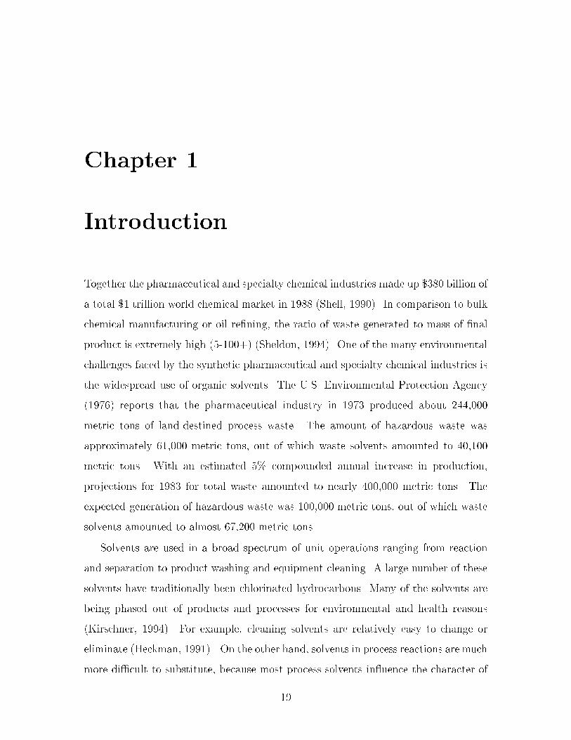
Pollution prevention ranks at the top of the national waste management hierarchy�
Source reduction and onsite� closed loop recycling are the recommended methods�
with less desirable strategies ranked in order of decreasing preference �see Figure ���
�The Pollution Prevention Act �U�S� Congress� ����b��� As increased attention is
devoted to waste management� we should observe a load shift from the alternatives in
the lower part of the hierarchy to the alternatives in the upper part� Experience indi
cates that on average about �� of emissions from chemical facilities are generated by
��� of the sources �Chadha and Parmele� ������ It is therefore important to identify
and focus on the major contributors� As stated by Friedlander ��� ��� �Although
waste reduction is an attractive concept� the total elimination of manufacturing waste
is beyond the capability of modern technology� The issue is really how to approach
the limiting goal in an expeditious and costeective manner��
Opportunities for waste elimination are present during the design and construc
tion of a new process� and when the process is in normal operation �Jacobs� ������
Pollution prevention aims to fundamentally redesign chemical manufacturing systems
in order to achieve or approach zero environmental impact� This philosophy should
be applied both to the design of new processes and to the modi�cation of existing
ones� In both cases this requires an approach that considers the overall impact of
any modi�cation on the entire processing system� and must encompass all aspects
��

Source ReductionThe reduction or elimination of waste
at the source, usually within the process.
RecyclingThe reuse of fractions or all of
a hazardous wastestream.
Waste TreatmentA process that renders waste nonhazardous,
less hazardous, amenable for storage,or reduced in volume.
DisposalThe controlled or uncontrolled discharging of
hazardous waste into or on to land, water, or air.
Figure ��� The national waste management hierarchy�
of process operation� The design phase involves the selection of chemical pathways�
unit operations� the overall �owsheet� operating procedures� etc�� and provides the
greatest potential for waste reduction� Currently� much attention is devoted to the
development of new chemical pathways and novel unit operations that reduce or elim
inate materials that are harmful to the environment �e�g�� Knight and McRae �������
Crabtree and ElHalwagi ������� and Baker et al� �������� A necessary complement
to these eorts is the ability to predict and analyze process behavior at a plant wide
level� For example� Grossman et al� ��� �� present a solution procedure for max
imizing net present value while minimizing overall toxicity during the synthesis of
chemical complexes� The problem is posed as a bicriteria mixedinteger program
ming problem� Douglas ������ demonstrates how his hierarchical design procedure
for continuous processes �Douglas� �� � can be extended to identify waste mini
mization problems as a design is evolving� and to identify process alternatives that
can be used to avoid or reduce these problems� The systematic approach proceeds
��

through a series of hierarchical levels� where additional process details are added at
each level� Some of the decisions that are made result in emission problems� which� if
identi�ed early in the design phase� can be eliminated� Rossiter ������ discusses how
process integration techniques are being applied to pollution prevention problems�
Illustrations are drawn from the three main areas of process integration� pinch analy
sis� knowledgebased approaches� and numerical�graphical optimization approaches�
Linninger et al� ������ presents a hierarchical approach leading to the synthesis of
batch processes with zero avoidable pollution� followed by a guided evolution to pro
cesses with minimum avoidable pollution� Lakshmanan and Biegler ������ apply
the concepts of reactor network targeting to the synthesis of process �owsheets with
minimum waste� Pistikopoulos et al� ������ introduce a systematic methodology for
obtaining process designs with minimum environmental impact� The methodology
embeds principles from life cycle analysis within a process optimization framework�
Diwekar �Summer ����� ����� discusses how existing process simulation technologies
and mathematical methods can be applied to addressing environmental concerns in
chemical process engineering� In particular� the incorporation of uncertainties into
the synthesis of advanced environmental control systems is emphasized�
So far� research activities have been successful only to a limited extent in address
ing the problems of waste generation in chemical processes� It is our opinion that
much of this de�ciency has arisen from a failure to recognize that the environmen
tal problems faced by the chemical industries require new approaches� as opposed
to adapting current design technologies� Systematic methods developed speci�cally
to address the needs of the industry and the legislators are essential to successfully
resolve the problems at hand� The recognition that the real opportunities lie in how
the environmental debate should change the way design is performed� rather than
vice versa� inspired formulation of the following procedure�
� study particular industries and speci�c environmental problems
� employ the insight and understanding gained to conceive one or more concrete
innovative approaches to address these problems
��
� de�ne a series of genuine technical problems that need to be resolved
This thesis serves as a modest example of how this approach can yield concrete
technical solutions leading to signi�cant environmental bene�ts�
��� Batch Process Design
Smaller companies especially �nd it hard to devote the eort needed for eective pro
cess development �Stinson� ������ This is partly due to pressure from the market� and
partly due to the fact that the cost of manufacturing pharmaceutical intermediates
and specialty chemicals is often marginal compared to the cost of the development
work up to the stage when the product is ready for largescale production� Hence�
there are often small economic incentives to improve manufacturing e�ciency� With
increased environmental pressure from regulatory agencies and government this is
likely to change�
Pharmaceutical products are typically required in small volumes� and are subject
to short product life cycles as well as �uctuating demand� Hence these industries are
dominated by the use of multipurpose equipment in batch processes� and waste is
generated in relatively small volumes with large variability and high concentration of
toxic species� These factors coupled with the inherently time dependent behavior of
the unit operations will strongly in�uence the manner in which pollution prevention
is pursued in batch process design�
In batch processing facilities a strong distinction exists between the batch process
and the batch plant� The plant refers to the multipurpose facility in which a variety
of products can be produced� while the process refers to the operating procedures and
production plans to manufacture an individual product within the facility� Allgor et
al� ������ observe that far more frequently the goal of batch mode engineering ac
tivities is the design of an e�cient process for a new or existing product rather than
the design of a �exible manufacturing facility� In fact� the new process is usually
incorporated into an existing facility� Extensive reviews of academic progress in this
�eld have been published �Rippin� �� �a� Rippin� �� �b� Reklaitis� �� �� Rippin�
��
����� and show that typical engineering tasks addressed by academic research in
clude equipment selection and sizing for plant construction� production planning and
scheduling� the treatment of uncertainty in these tasks� and batch process simulation�
However� the rapid design of e�cient batch processes has received little academic
attention �Allgor et al�� ������
Some of the problems arising in the design of batch processes can be identi�ed
�Rippin� �� �b��
� Understand and optimize the performance of tasks carried out in individual
items of equipment�
� Optimize the performance of a sequence of tasks in several equipment items to
produce a single product�
A task carried out in a particular item can be characterized by the extent to
which the task is performed� the time required� and the capacity requirement �Rip
pin� �� �a�� Rippin ��� �b� observed that although optimal operation of individual
equipment items is important� coordination of tasks is necessary to give optimal op
eration at a system level� as the performance of an upstream unit determines the
input to a downstream unit �and vice versa if material is recycled�� This issue has
been addressed by several workers in the �eld� e�g�� Hatipoglu and Rippin ��� ���
Wilson ��� ��� Barrera and Evans ��� ��� Salomone and Iribarren ������� and All
gor et al ������� An important observation made by Barrera and Evans ��� �� is
that in previous research the objective had been to minimize capital cost� although
a more appropriate objective function would be the minimization of total manufac
turing cost� including rental cost of the capital equipment� raw materials� energy�
and labor� Three generic tradeos in the optimal design problem are also formally
introduced� The �rst type occurs within an individual unit� where there is a tradeo
between the cycle time of the unit and the intensity of processing� The second type
of tradeo occurs amongst units� as the performance of an upstream unit determines
the input to a downstream unit� The third tradeo is a combination of the two other
types� and trades o the total rental costs for all the units against the cost factors
��

determined by the total processing rate for the entire system� Optimal batch process
design requires that all these tradeos are considered simultaneously� Increasing en
vironmental concerns introduces an additional design objective� the environmental
impact of the process� Today� the ability to take into account these issues at the
development stage is vital to generating an attractive and acceptable process�
Unfortunately� today s environmental legislation appears to be solely focused on
continuous processing and dedicated batch manufacturing� For example� recovery
of toxic materials through recycling is only credited if it is an onsite closed loop
process with no intermediate storage� This is typically very di�cult to satisfy in
a batch process� as the intermittent nature of the process almost always requires
some temporary intermediate storage to make recycling feasible� A more appropriate
de�nition for pollution prevention in multiproduct batch facilities is therefore the
task of integrating source reduction and recovery of materials in such a way that any
waste treatment or disposal is made redundant� In this context� the eective recovery
and recycling of solvents is a primary concern� As De Wahl and Peterson ������ note�
�though changing an industrial process is frequently cited as the most desirable way to
reduce waste for true pollution prevention� the bene�ts of recycling� however� tend to
be more obvious and often aect waste volumes dramatically�� Berglund and Lawson
������ suggest that the permitting process for environmentally sound recycling of
waste streams should be streamlined to enhance the attractiveness of such pollution
prevention options�
��� Approach
Several technologies are available to analyze dierent aspects of a process design� For
example� batch process development is typically conducted by the use of laboratory
scale experiments and test runs in pilot plants� In addition� steadystate simulators
for extraction of physical properties� and dynamic simulation models customized for
selected unit operations �e�g�� BATCHFRAC �Aspen Technology� ������ are some
times employed� However� no single tool or approach can appropriately capture all
��

the issues� In this research we propose a prototype technology which utilizes a com
bination of tools�
�� Rigorous dynamic simulation models and�or plant data are used to predict the
compositions and magnitude of wastesolvent streams�
�� Recent research results from the analysis of residue curve maps are exploited
and extended to target for the maximum feasible recovery when using batch
distillation�
�� This information is used to suggest design modi�cations� The new design is
then analyzed for further improvements� returning to step ��� if necessary�
�� Dynamic simulation models are employed to analyze the dynamic behavior of
the generated process alternatives�
Chemical species in wastesolvent streams typically form multicomponent azeotropic
mixtures� This highly nonideal behavior often complicates separation and hence re
covery of the solvents� Our approach is based on understanding and mitigating such
obstacles� A simple batch process consisting of a reactor and a recti�er is presented in
Figure �� to illustrate the procedure� Although simple� the problems encountered in
this �owsheet are representative of the class of processes studied in this work� Com
ponent R reacts to form product P and byproduct BP� R is exhausted by the reaction�
BP is undesired and is treated as organic waste� while it is desirable to recover and
recycle the solvent S� The feasibility of distilling the ternary mixture P� BP� and S
can be determined from a study of the relevant ternary residue curve map �see Figure
��b�� S and BP form a maximum boiling binary azeotrope SBP� As a consequence�
only one of the species S and BP can be recovered in pure form� The two possible
distillation sequences are �� S � SBP � P and �� BP � SBP � P� depending on
the initial composition in the reboiler� If alternative � is chosen� pure S is recovered
and can be recycled to the subsequent batch� However� the binary azeotrope SBP
will have to be disposed of� as it is the only means by which BP can be removed from
the system� Hence� extra solvent has to be added to the process with every batch�
��

and subsequently disposed� On the other hand� alternative � will result in recovery
of nearly pure BP� which is also subject to disposal� while the binary azeotrope can
be recycled to the subsequent batch� Alternative � obviously provides environmental
bene�ts over alternative � because nearly all of the solvent is recovered and recycled�
Some organic waste �BP� is generated� but this is a result of the stoichiometry and is
unavoidable without altering the chemistry� In conclusion� this analysis has revealed
that the �nal reaction mixture should ideally have a composition that is located in the
region bounded by BP� SBP� and P� This can be achieved in principle by adjusting
the amount of solvent added to the reactor during startup before cyclic steadystate
is reached� Before implementation in plant the impact of recycling BP through the
SBP azeotrope on the reaction kinetics must be analyzed�
Solvent (S)
Products (P)
Waste
Reactants (R)
Recycle
R P + BP
TBPP,
TBS,
TBS-BP
TBBPBP,
S
•a) b)
Figure ��� a� A simple process consisting of a reaction task and a separation task�b� The residue curve map for the mixture leaving the reactor�
As demonstrated in the example� the sequence of pure component and azeotropic
cuts generated by batch distillation of a multicomponent azeotropic mixture� and the
maximum feasible recovery in each cut� is highly dependent on the initial composition
of the mixture� Any species that is recovered in azeotropic cuts that cannot be
recycled is likely to leave the process and be treated as toxic waste� The ability to
predict the feasibility of recovering components in pure form from a process stream is
therefore essential to pollution prevention in these manufacturing systems� The use of
batch distillation as a multipurpose separation operation is typical in the industries
concerned� Economics and simplicity of control make batch distillation one of the
�

most attractive methods for solvent recovery �Hassan and Timberlake� ������ This
work presents a rapid and automated approach to generating this prediction� assuming
that batch distillation is the separation technique employed�
The approaches currently available to obtain such predictions� e�g�� test runs in
pilot plants or detailed dynamic simulation models are typically very elaborate and
time consuming� On the other hand� Van Dongen and Doherty ��� �a� show that
the desired information can be readily extracted from the residue curve map that is
characteristic of simple distillation� In this research the theory for ternary and qua
ternary residue curve maps is extended and generalized to systems with an arbitrary
number of components� The body of theory is derived from the �elds of nonlinear
dynamics and topology �see� for example� Guckenheimer and Holmes ��� �� or Hale
and Ko!cak ��������
These theoretical results lead to the development of systematic and general tools
for the design of batch processes with minimum waste� An algorithm for elucidat
ing the structure of the batch distillation composition simplex for a system with an
arbitrary number of components is developed� Identi�cation of the batch distilla
tion regions is accomplished through completion of the unstable boundary limit sets�
The completed boundary limit sets accurately represent the topological structure of
the composition simplex� and also makes it possible to extract all product sequences
achievable when applying batch distillation�
The algorithm for characterizing the batch distillation composition simplex for
a system with an arbitrary number of components is then exploited in a sequential
approach where the process modi�cations proposed by the engineer are evaluated�
This approach places the composition of the mixture correctly in the map� and com
putes the maximum feasible amounts that can be recovered when employing batch
distillation� This procedure will be termed solvent recovery targeting�
Furthermore� a framework that allows automatic and simultaneous evaluation of
all feasible distillation sequences from both thermodynamic and environmental or
economic perspectives is developed� The framework is realized as a mathematical
program� This methodology can be employed to generate various designs alternatives
��

by adding or removing design constraints� thereby furnishing the engineer with a
set of dierent process designs that can be evaluated based on other criteria not
embedded in the program� such as reaction rates �which is a function of selected
solvent�� production times� safety� etc�
Chapter � demonstrates and addresses the de�ciencies in earlier work on ternary
residue curve maps� In Chapter � these results are used to guide the development
of a complete set of concepts to describe batch distillation of an azeotropic mixture
with an arbitrary number of components� The material in Chapters � and � is an ex
tended version of the material in Ahmad and Barton �����b�� Chapter � presents the
algorithm for characterizing the batch distillation composition space� Chapter � in
troduces solvent recovery targeting� and presents results from two case studies where
solvent recovery targeting is applied� Chapter � presents a systematic approach to
the generation of batch process designs that have solvent recovery and recycling in
tegrated into the �owsheet� The approach is realized as a mathematical program� In
Chapter � the results from two case studies where the mathematical programming
approach is used are discussed� The material in Chapters � and � is an extended
version of the material in Ahmad and Barton ������� Chapter extends the math
ematical programming approach to provide a general framework for the design of
multiproduct batch manufacturing facilities in which solvent use is integrated across
parallel processes� Chapter � discusses the results from two case studies where the
extended mathematical programming approach is utilized� The material in Chapters
and � is an extended version of the material in Ahmad and Barton �����a�� Finally�
Chapter �� presents conclusions and recommendations for future work�
��

Chapter �
Analysis of Batch Distillation
Systems
Separation of multicomponent azeotropic mixtures into pure products is a common
problem in most sectors of the chemical industry� whether it be through the use
of continuous distillation or batch distillation� It is now generally recognized that
dynamic investigations of processes and equipment are essential to understand ade
quately the behavior and performance of these operations� A good deal of eort has
been spent on exploring the dynamic behavior of simple distillation of multicompo
nent mixtures� The concept of residue curve maps has been introduced to facilitate
graphical analysis of such systems� This has led to a number of results that can be
used in the synthesis and design of complex distillation systems� A number of articles
have addressed continuous systems �Doherty and Caldarola� �� �� Levy et al�� �� ��
Stichlmair and Herguijuela� ����� Stichlmair et al�� ����� Van Dongen and Doherty�
�� �a� Wahnschat et al�� ����� Wahnschat et al�� ������ To a lesser extend the syn
thesis of batch distillation systems has been addressed� The bulk of this research has
focused on low dimension systems �binary� ternary and quaternary systems� and the
generation of ternary residue curve maps� The work on simple distillation and ternary
batch distillation is reviewed� and the de�ciencies are identi�ed and addressed� In
subsequent chapters these results are used to guide the development of a complete set
of concepts to describe batch distillation of an azeotropic mixture with an arbitrary
��

number of components�
��� Characterizing Distillation Systems
Binary distillation� where one component is separated from another� is the simplest
form of distillation� The homogeneous phase equilibrium between two components
can be represented by a vapor�liquid equilibrium curve at constant pressure� This
curve contains all possible pairs of liquid and vapor compositions in equilibrium with
each other and is completely independent of any consideration concerning the distilla
tion setup except the total pressure� Corresponding plots also showing the equilibrium
temperature are termed Txy�diagrams and include both bubble and dewpoint curves�
Given a boiling temperature the corresponding vapor and liquid compositions can be
read directly o the diagram� Alternatively� for a given liquid �or vapor� composition
the composition of the vapor �or liquid� at equilibrium can be found� as well as the
boiling or dewtemperature� Depending on the system� the diagram takes on qual
itatively dierent forms as shown in Figure ��� a� the system forms no azeotropes�
b� the two components form a minimum boiling binary azeotrope� and c� the two
components form a maximum boiling binary azeotrope� Although extremely rare�
multiple azeotropy may be observed� where the same components form azeotropes
with dierent compositions and boiling temperatures� This occurs when the system
exhibits very strong positive and negative deviations from Raoult s law in dierent
areas of the composition space� The only known example of a double azeotropic mix
ture is the system C�H�C�F� �see� for example� Dechema s VaporLiquid Equilibrium
Data Collection Vol��� Part � ��� �� or Doherty and Perkins ���� a��� In this work
multiple azeotropy is not discussed� However� the theory derived in Chapters � and
� is also applicable to such phenomena�
Vaporliquid equilibrium data can be generated using the least complicated of all
distillation processes� the simple distillation �or open evaporation� process� Here a
multicomponent mixture is boiled in an open vessel at constant pressure such that
the vapor is removed as soon as it is formed �see Figure �� where xi and yi are the
��

0 1
Tem
pera
ture
0 1
Tem
pera
ture
0 1
vapor/liquid molefraction for component i
Tem
pera
ture
xaz,i = yaz,ixaz,i = yaz,i
vapor
liquid
vapor
vapor
liquid
liquid
vapor/liquid molefraction for component i
vapor/liquid molefraction for component i
a) b) c)
Figure ��� Binary vaporliquid equilibrium diagrams exhibiting a� no azeotrope� b�a minimum boiling binary azeotrope� and c� a maximum boiling binary azeotrope�
mole fractions of component i in the liquid and the vapor phase� respectively�� The
liquid �or residue� will become increasingly depleted in the more volatile component
as the distillation progresses� The change in the composition of the residue during
simple distillation of an nc component mixture can be represented as curves that lie
in an nc � � dimensional composition hyperplane called a residue curve map� The
residue curve maps for the binary systems in Figure �� are shown in Figure ���
yi
xi
Heat
Figure ��� Setup for simple distillation�
A study of the residue curve maps in Figure �� yields the important information
that an azeotrope acts as some kind of barrier to separation� For example� if the
liquid feed composition is located to the right of the azeotrope in Figure ��c� the
vapor will initially be rich in component i� As the liquid composition approaches
xaz�i� the vapor composition will do the same� However� when the liquid reaches the
azeotropic composition it will not change� no matter how much heat is applied� On
��

xi = 0 xi = 1 xi = xaz,ixi = 0 xi = 1 xi = 0 xi = 1xi = xaz,i
Liquid molefraction for component i
a) b) c)
Liquid molefraction for component iLiquid molefraction for component i
Figure ��� Binary residue curve maps for systems exhibiting a� no azeotrope� b�a minimum boiling binary azeotrope� and c� a maximum boiling binary azeotrope�Direction of arrow indicates increasing boiling temperature�
the other hand� with the liquid feed composition located to the left of the azeotrope�
we will observe vapor compositions in the range from very little i to the azeotropic
composition� Hence� we also observe that depending on which side of the azeotrope
we are operating dierent separation alternatives will result� Residue curve maps can
provide the means to enumerate the number of possible separation alternatives� Ob
viously� Txydiagrams yield more information than residue curve maps and would be
preferred� However� as the number of components increases graphical representation
becomes increasingly di�cult� Vaporliquid equilibrium of ternary systems is most
easily studied in residue curve maps� and for systems with more than four compo
nents there is no straightforward way of studying the separation behavior of a mixture
graphically� Now� going from binary to ternary to multicomponent systems� there is
literally an explosion in the number of separation alternatives� The main focus of this
work is to try to understand this vast number of alternatives� and if possible provide
an automatic means to enumerate them for a given system�
��� Simple Distillation Residue Curve Maps
For ternary systems the residue curves may be represented either in a regular simplex
or in a right simplex� The regular simplex is the well known Gibb s composition
triangle� and the right simplex is generated by projecting the composition plane onto
a plane de�ned by xi � �� i � f�� �� �g� The relationship between the two represen
tations is shown in Figure ��� where the vertices represent pure components� binary
azeotropes are located on the edges� and any ternary azeotrope is found inside the
simplex� For the purposes of this work� it is most valuable to imagine the Gibb s
��

composition simplex suspended in the host nc space�
Gibb's composition triangle
Gibb's composition triangleprojected onto the plane x2 = 0x1
x3
x2
Figure ��� The relationship between the regular and the right simplex representations of ternary residue curve maps�
The vectors through the three pure component vertices form a basis for the three
dimensional vector space R�� but because the mole fractions must sum to unity�
the actual feasible composition space is a regular simplex that lies on the plane
x� � x� � x� � � and is constrained by xi � � �i � �� �� �� Hence� in an nc compo
nent system the vectors through the nc pure component vertices form the basis for
the nc dimensional vector space Rnc� and the composition space is a closed nc � �
dimensional regular simplex on the hyperplanePnc
i� xi � � constrained by the closed
half planes xi � � �i � �� �� � � � � nc� The simple distillation residue curves can be
constructed experimentally using the distillation setup described above� or can be
found numerically by solving a set of equations describing the composition path of
the residue� The derivation of these equations can be found in Doherty and Perkins
�������dxi
d�� xi � yi�x� �i � �� � � � � nc� � �����
The relationship between xi and yi can� for example� be described by a suitable vapor
liquid equilibrium model �see� for example� Prautsnitz et al� ��� ���� The independent
variable � is a dimensionless measure of time� Residue curves �orbits�z are projections
of the trajectories de�ned by Equations ����� onto the plane � � � �i�e�� the phase
��

portrait of the dynamic system�� Equations ����� can be analyzed� and a number of
properties regarding the structure of the residue curve map for the system of interest
can be extracted� The mathematical basis for multicomponent simple distillation
theory can be found in a series of papers by Doherty and Perkins ���� a� ��� b� ������
The residue curves also represent the column pro�le in a column that is operated at
total re�ux� indicating that the top and the bottom product compositions in that case
have to be located on the same residue curve� The residue curves can be grouped
into families of curves that have qualitatively similar trajectories� Most of the residue
curve maps presented here are for simplicity shown with only one or two residue curve
representing a certain family of curves� but� of course� an in�nite number of curves
may be drawn� An example of the residue curve map �regular simplex� for a ternary
system with components L� I� and H is shown in Figure ��� Components L and I
form a maximum boiling azeotrope� The arrows point in the direction of increasing
temperature and time�
residue curves
TBHH,TB
II,
TBLL,
•TBL-I
Figure ��� Simple distillation residue curve map for ternary system with a binarymaximum boiling azeotrope� L� I� and H are the low� intermediate� and high boilingpure components in the system� respectively� The order of boiling temperatures isTLB � TI
B � TL�IB � TH
B � � indicates azeotrope�
The problem of computing the temperatures and compositions of all the azeotropes
in a multicomponent system can be formulated as a multidimensional root�nding
zThe terminology describing the dynamic system x��� is adopted from Hale and Ko�cak �������
��

problem� where the pure components and azeotropes are the �xed points �critical
points� equilibrium points� steadystate solutions� of the dynamic system� The �xed
points can be shown to have the properties of nodes or saddles �Doherty and Perkins�
����� Doherty and Perkins� ��� a�� The nodes represent either lowboiling or high
boiling compositions� while the saddles represent intermediateboiling compositions�
here referred to as x�m� x�q� and x�n� respectively� x�m is an unstable node which all
residue curves in the same family will enter as � � ��� x�q is a stable node which
all residue curves in the same family will enter as � � ��� and x�n has no residue
curves entering except for the residue curves that are also separatrices �see Section
����� In Figure �� the pure components L and I are unstable nodes� component H
is a stable node� and the binary azeotrope LI has the properties of a saddle point�
The nature of the �xed points can be classi�ed using topology theory �Doherty and
Perkins� ����� Fidkowski et al�� ������ The set ��"x� � lim�������� "x� is called the
�limit set of composition point "x� Similarly� the set ��"x� � lim������� "x� is called
the �limit set of "x �Hale and Ko!cak� ������ ���� "x� refers to the trajectory through
"x� Clearly� following from the properties above ��"x� and ��"x� only contain �xed
points� as all trajectories approach �xed points as � � �� and � � ��� and the
trajectories �ll the entire composition simplex� Therefore� each composition point in
the composition simplex may be characterized by a �xed point as its �limit set and
another �xed point as its �limit set�
��� The Use of Residue Curve Maps in Batch Dis�
tillation
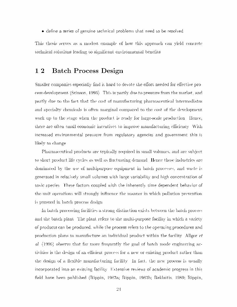
Reinders and De Minjer ������ study the dierences between residue curves �simple
distillation lines� and distillation lines that describe recti�cation� or traditional batch
distillation� In recti�cation the feed is heated in a reboiler and product is condensed
and drawn overhead �see Figure ���� They present several examples of ternary
residue curve maps� and indicated that under certain conditions the lines of rectifying
��
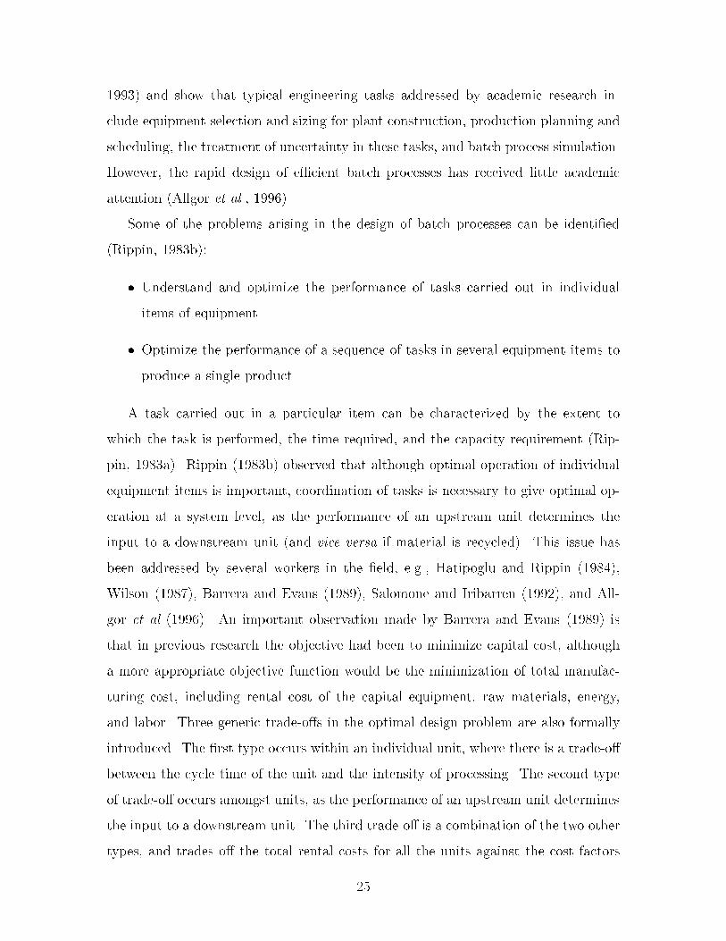
distillation will be almost straight� Figure �� illustrates this behavior for a system
with no azeotropes� The conditions under which this behavior may be observed�
however� are less clear� The authors argue that the distillation lines may deviate
from this behavior if the holdup in the tray section is large compared to the reboiler
volume� and the less ideally the column works�
xip
reboiler1
N
N - 1
xdi
condenser
Figure ��� Setup for recti�cation or traditional batch distillation�
TBHH,TB
II,
TBLL,
TBHH,TB
II,
TBLL,
a) b)
Figure ��� Residue curve map for a ternary system with no azeotropes� a� simpleresidue curve map� b� residue curve map with distillation lines that describe recti�cation�
Van Dongen and Doherty ��� �b� prove that for ternary batch distillation with
high re�ux and a large number of equilibrium stages the rectifying distillation lines
�

do indeed move in such a manner� They demonstrate that when distilling a ternary
mixture under these limiting conditions it is possible to draw the exact orbits following
the composition of the liquid in the still� and to predict the sequence of constant
boiling vapor distillates overhead� provided only that the structure of the residue curve
map for the system of interest is known� This is particularly important for azeotropic
mixtures� as the sequence of products will typically change with feed composition�
A simple batch distillation model was developed describing the time evolution of the
composition in the still pot�
dxpi
d�� x
pi � xdi �x
p� �i � �� � � � � nc� � �����
where xpi is the mole fraction of component i in the still pot and xdi is the fraction in
the distillate as illustrated in Figure ��� It is important to note that this equation
is dierent to the simple distillation Equations ����� as xdi is not in equilibrium with
xpi � Rather� xdi is calculated �given x
pi � using the design equations for the column�
The set of equations used was based on the assumption of high re�ux ratio �rr � ���
With few theoretical stages �small N�� the batch distillation residue curves calculated
look similar to the residue curves from simple distillation� as expected� When N
is increased to a high value �i�e�� N � ������ the batch distillation residue curves
�xp���� appear to move directly away from the initial composition point xp�� in a
direction opposite from the position of the lowboiling �xed point �pure component
or azeotrope� in the region where xp�� was located� xp��� denotes the pot composition
trajectory ��p���� projected onto the plane � � �� The change in the pot composition
xp��� is almost linear because a large number of trays and high re�ux ratio cause the
composition of the distillate xd��� to be approximately constant at a value near the
lowboiling �xed point� The composition of the pot will move along this straight line
until it hits a pot composition barrier �see Section ����� then it will turn and follow the
limiting boundary towards the higher boiling �xed point� For each batch distillation
residue curve there will be a corresponding distillate curve that denotes the locus of
distillate compositions xd��� as they change with time during the course of distillation�
��

The relationship between these two curves is precisely the same as the relationship
between a simple distillation residue curve and its vapor boilo curve� Hence� the
distillate composition xd���
� corresponding to any particular instantaneous still pot
liquid composition xp���
� will lie on the tangent line to the batch distillation residue
curve through xp���
� �see Equations ������� The two instantaneous compositions also
have to lie on the same simple distillation residue curve due to the assumption of
close to total re�ux in the column� In Figure � the relationship between the pot
liquid composition xp��� and the distillate composition xd��� during the course of
distillation is shown for a ternary mixture� xp�� is the initial composition in the
reboiler� The white arrow indicates the orbit xp���� The set of points xd��� xd��� and
xd�� represents the distillate curve� i�e�� the sequence of distillate compositions that
will appear overhead if the column is run until the reboiler is dry�
x p,0+
xd,1
pot compositionbarrier
TBLL,
TBHH,TB
II,
TBL-I
•
xd,3
xd,2
x p(ξ)
Figure �� Relationship between pot composition xp��� and the distillate composition xd��� during the course of distillation of a ternary mixture�
It has been demonstrated that this behavior also applies to mixtures with more
than three components� For example� Bernot et al� ������ present an example with
four components� However� no attempt has been reported at extending and general
izing the theory to mixtures with an arbitrary number of components� In this work
the theory governing the behavior of such a mixture is introduced� A recti�er con
�guration is assumed� but the same arguments will apply for a stripper con�guration
��

�see Appendix A��
��� Distillation Boundaries
The presence of distillation boundaries in the composition space� and whether these
boundaries can be crossed or not using continuous or batch distillation� have been
the topic of considerable debate in the literature over the years� The separatrices
play a central role� where a separatrix is de�ned in the following manner� if in each
neighborhoodx Nr�p� of a point p there is a point q such that ��q� �� ��p�� or
��q� �� ��p�� then the orbit through p is called a separatrix �Hale and Ko!cak� ������
It is important to understand the dierence between stable and unstable separatrices�
A stable separatrix is de�ned as a residue curve where the residue curves on each side
are moving towards the same �xed point� and which are moving towards this same
�xed point even at long time� Otherwise the separatrix is an unstable separatrix�
Doherty and Perkins ���� a� conclude that unstable separatrices correspond to simple
distillation boundaries�
Much discussion has evolved around the dierence between simple distillation
boundaries and the distillation boundaries related to a speci�c distillation con�gu
ration �e�g�� continuous� batch recti�er� batch stripper� etc��� Reinders and De Min
jer ������ analyze the general structure of simple distillation curves and distillation
curves of rectifying distillation for systems with no azeotropes� one minimum boiling
binary azeotrope� one maximum boiling binary azeotrope� and combinations of bi
nary and ternary azeotropes� and conclude that for some systems a boundary line for
simple distillation may induce a similar boundary line for recti�cation� However� for
other systems this correlation may be lacking� Ewell and Welch ������� after study
ing �ve ternary systems using a recti�er� summarize that three types of boundaries
are observed� �� straight boundaries associated with valleys in the boiling tempera
ture surface� �� curved boundaries associated with ridges in the boiling temperature
xA neighborhood of a point p is a set Nr�p� consisting of all points q such that the distanced�p� q� � r� The number r is called the radius of Nr�p� �Rudin� ����
��

surface� and �� straight boundaries that are not associated with any feature in the
boiling temperature surface� Although it appeared to Ewell and Welch that some of
the boundaries they observed were associated with valleys and ridges in the boiling
temperature surface� we know now that this correlation with features on the boiling
temperature surface was only an artifact of the particular systems they were studying�
It has been widely believed that separatrices in a simple distillation residue curve
map coincide with the projection of ridges and valleys in the boiling temperature
surface onto the composition simplex� Hence� the separatrices can be located by
studying the structure of the boiling temperature surface� For example� Doherty and
Perkins ���� a� describe a simple algorithm to locate the boundary structure for an
nc component system by detecting the valleys and ridges based on stability criteria for
the boiling temperature surface� However� over the years there have been indications
that this prevailing opinion is false� Swietoslawski ������ compares experimental data
for valleys and ridges with the corresponding simple distillation residue curve maps�
and demonstrates that there are deviations� Naka et al� ������ without rigorous proofs
also come to the same conclusion� The last words on the subject may have been said
when Van Dongen and Doherty ��� �� demonstrate that valleys and ridges do not
necessarily coincide with separatrices by analyzing the equations governing the boiling
temperature surface and the simple distillation process� They show through several
examples that there is no correlation between the separatrices and the valleys and
ridges in the boiling temperature surface� The curved boundaries actually correspond
to separatrices� In simple distillation unstable separatrices� by de�nition� cannot be
crossed by the orbit of the liquid composition �a separatrix is just another residue
curve� and residue curves cannot cross�� On the other hand� it may be feasible to
achieve distillate compositions on the other side of the boundary� In continuous
distillation� unstable separatrices can be crossed under certain conditions� if the
boundary is highly curved and the feed composition is in the concave region of the
boundary line� it may be possible to achieve product compositions on the other side
of the boundary �Stichlmair and Herguijuela� ����� Wahnschat et al�� ������ Ewell
and Welch ������ speculate concerning the crossing of curved boundary lines using a
��

traditional batch column� They conclude that both residue and distillate composition
orbits can cross the boundary when approaching from the concave side� but not
from the convex side� As Doherty and Perkins ���� a� later point out� the residue
composition orbit cannot cross the boundary �as this would give rise to intersecting
residue curves�� However� as the distillate is not in equilibrium with the residue in a
batch column� it is feasible for the distillate composition orbit to cross the boundary�
This issue is elaborated further in the next section�
�� Distillation Regions
The de�nition of distillation regions and boundaries are closely related� Doherty and
Perkins ���� a� state that two simple distillation residue curves that are initially close
together and are still close at long time belong to the same simple distillation region�
Clearly� the residue curves in Figure �� can be divided into two families� those that
enter L as � � �� and H as � � ��� and those that enter I as � � �� and H
as � � ��� However� according to the de�nition by Doherty and Perkins ���� a��
all the residue curves belong to the same region� and hence there is only one simple
distillation region in the map� In batch distillation the situation is dierent� At this
point it is necessary to de�ne a batch distillation region� and we adopt a modi�cation
of the de�nition due to Ewell and Welch �������
De nition �� A batch distillation �recti�cation or stripping�� region B�P� is the
set of compositions that lead to the same sequence of product cuts P � fp��p�� � � �g
upon distillation �recti�cation or stripping� under the limiting conditions of high
re�ux ratio and large number of equilibrium stages�
Under the limiting conditions� a product cut sequence is de�ned as the sequence of
pure component and azeotropic compositions �pk �k � �� �� � � �� drawn overhead when
distilling a multicomponent mixture using batch distillation� The element pki in the nc
vector pk is the mole fraction of pure component i in product cut k� For an azeotropic
�The theory is derived for the more common recti�er con�guration�
��

mixture this product cut sequence depends on the location of the composition of the
feed� and by de�nition any initial composition that is taken interior to a given batch
distillation region will always result in the same sequence of cuts� Hence� once the
batch distillation regions are de�ned� the set of products can be predicted from the
distillate path thus de�ned� As Figure � shows� the residue curve map for the
components L� I� and H presented in Figure �� can actually be divided into two
batch distillation regions� one de�ned by the straight lines connecting L�LI� and H
giving rise to P� � fL�LI�Hg� and one de�ned by the straight lines connecting I�LI�
and H resulting in P� � fI�LI�Hg� Figure �� presents another example� Components
L and I form a minimum boiling binary azeotrope� and so do components I and H�
The composition space is divided into three batch distillation regions� B�� B�� and
B�� The feed composition xp�� is located in batch distillation region B�� The resulting
product cuts therefore are� �� the binary azeotrope LI with composition xd��� ��
the pure component L with composition xd��� and �� the pure component H with
composition xd���
xd,2
xd,3
xp,0
+
batch distillationboundaries
batch distillationregions
1
2
3xd,1
TBI-H
TBL-I
L, TBL
I, TBI
H, TBH
•
•
Figure ��� Ternary residue curve map with batch distillation boundaries and regions� The order of the boiling temperatures is TL�I
B � TLB � TI�H
B � TIB � TH
B �
The boundaries that Ewell and Welch ������ observed have later been termed
batch distillation boundaries �see Figure ���� Bernot et al� ������ ����� propose how
the batch distillation boundaries can be found for a ternary system�
��

�� The stable separatrices dividing the simplex into subdomains each containing
an unstable node constitute batch distillation boundaries�
�� Within each of these subdomains �or the entire simplex in the case of only one
domain�� connections between the unstable node and all the other species in
the domain may be introduced as straight line batch distillation boundaries�
A straight line boundary should not intersect a stable separatrix� and if a stable
separatrix is highly curved� the straight line boundary is tangent to the separatrix� For
example� in the ternary residue curve map in Figure ���a the boundary connecting
component I and the binary azeotrope LH will intersect the stable separatrix between
LIH and LI and should therefore be discarded� Figure ���b illustrates another
example� When placing batch distillation boundaries according to the above rules
a boundary connecting L and H will be introduced� However� as this boundary will
intersect the binary edge LH� it should be discarded� Another interesting feature
of the latter system is that any initial pot composition xp��� xi � � will yield the
product sequence P � fL�I�Hg� Compositions on the �L�I� edge� or the �I�H� edge
will yield a subset of P� fL�Hg� or fI�Hg� respectively� In contrast� compositions on
the binary edge �L�H� will yield fL�LHg� or fH�LHg� depending on which side of
the LH azeotrope the initial composition is located� This irregular behavior will only
be apparent if the initial composition is located on the edge� In Section ��� a clear
distinction will be made between the case when the initial composition is located
internal to a batch distillation region� and when it is located on the boundary of a
batch distillation region�
As demonstrated by Ewell and Welch ������ it is possible to obtain distillate com
positions on the other side of a stable separatrix when running a recti�er under the
limiting conditions of high re�ux ratio and large number of trays� When distilling
mixtures of acetone� chloroform� and methanol� the researchers observed a nonmono
tonic variation in the distillate temperature for certain initial reboiler compositions�
Ewell and Welch could not explain their �ndings� and concluded that the temperature
drop was an anomaly� Van Dongen and Doherty ��� �b� showed that this �anomaly�
��

TBHH,TB
II,
•TBL-H
b)a)
TBLL,
TBHH,TB
II,
TBLL,
• TBL-HTB
L-I
TBL-I-H•
•
Figure ���� Residue curve maps where some batch distillation boundaries arediscarded� The order of boiling temperatures� a� TL�m
B � TI�mB � TH�m
B � TL�I�H�nB �
TL�I�qB � TL�H�q
B and b� TL�mB � TI�n
B � TH�nB � TL�I�q
B �
has a logical explanation related to the curvature of stable separatrices� Figure ���
shows the residue curve map for the system acetone� methanol� and chloroform with
batch distillation boundaries placed according to the above rules� Stable separatri
ces are indicated with solid lines� while the other boundaries are dashed �long dash
segments�� Unstable separatrices are shown for clarity �short dash segments�� When
the pot orbit starting in xp��� hits the stable separatrix connecting the binary acetone
chloroform azeotrope and the ternary azeotrope it is forced to stay on this boundary�
and the pot composition xp��� will therefore follow the curvature of the separatrix�
The instantaneous distillate composition xd���
� will lie on the tangent line to the
pot orbit through the instantaneous pot composition xp���
� �see Equations �������
Hence� the distillate composition will not be equal to the ternary saddle azeotrope�
but will have a composition which will vary along the unstable separatrix connecting
the binary azeotrope acetonemethanol and the ternary azeotrope� A decrease in the
distillate temperature may therefore be detected� before the temperature eventually
increases again as the distillate composition path reaches the binary acetonemethanol
azeotrope� The deviation from the ternary saddle azeotropic composition will depend
on the curvature of the stable separatrix� Distillation of an initial reboiler composi
tion located in batch distillation region B� will result in a similar outcome with some
distillate compositions located on the other side of the stable separatrix� On the other
��

hand� initial compositions taken within regions B� and B� will not result in distil
late compositions located on the other side of the stable separatrices� For example�
when the pot orbit starting with xp��� hits the stable separatrix connecting the ternary
azeotrope and the binary acetonechloroform azeotrope the corresponding distillate
orbit will follow the same path as the distillate orbit resulting from xp��� �i�e�� at that
point the distillate composition will vary along the unstable separatrix connecting the
binary azeotrope acetonemethanol and the ternary azeotrope�� Hence� the distillate
orbit will not cross the stable separatrix� A detailed discussion of the other possible
product sequences can be found in Bernot et al� �������
•
••
Acetone329.3 K
Methanol337.7 K
Chloroform •334.9 K 327.4 K
330 K
327.7 K
338.3 K1
2
3
5
4
xp,01
+
xp,0+ 3
6
Figure ���� Residue curve map �qualitative� for the system acetone� chloroform�and methanol�
The signi�cance of these results is that highly curved stable separatrices may lead
to distillate orbits where the temperature is not monotonically increasing� If the pot
orbit hits the stable separatrix from the concave side� distillate compositions on the
other side of the separatrix may be achieved� Conversely� when the pot orbit hits the
stable separatrix from the convex side� the distillate orbit will not cross the separatrix�
but will move back into the original batch distillation region�
��

�� Pot Composition Boundaries in Ternary Mix�
tures
A stable separatrix does not necessarily divide the composition space� Figure ���a
shows a topologically consistent residue curve map with a single simple distillation
region where a stable ternary node is connected to a binary saddle azeotrope with
a stable separatrix� There is only one unstable node �L� in the composition space�
However� when the pot orbit hits the stable separatrix� it will be constrained to stay
on this boundary� Three batch distillation regions can therefore be constructed� as
indicated in Figure ���b� Feed compositions in region B� will give rise to P� � fL�I�I
Hg� B� will give rise to P� � fL�IH�LIHg� and B� will give rise to P� � fL�H�IHg�
This behavior is� in fact� completely ignored by other workers� for example Bernot et
al� ������ and Safrit and Westerberg �������
TBHH,TB
II,
TBLL,
TBI-H
•
•
TBL-I-H
1
2
3
TBHH,TB
II,
TBLL,
TBI-H
•
•
TBL-I-H
a) b)
Figure ���� Ternary residue curve map where stable separatrix does not dividethe composition space� The order of boiling temperatures� TL�m
B � TI�nB � TH�n
B �
TL�I�nB � TL�I�H�q
B �
It is now evident that all stable separatrices will constrain the movement of the
pot orbit� Residue curves are approaching from either side� Hence� the pot orbit is
restricted to move ever closer to the stable separatrix� and �nally� to follow the same
path as the separatrix� Here� we present the less obvious result that certain unstable
separatrices also play the role of impassable boundaries� Figure ���a shows a topo
�

logically consistent residue curve map containing a saddle ternary connected to three
binary azeotropes and pure component H by separatrices� Only stable separatrices
are shown� Two of the binaries are unstable nodes �LI and IH�� while the third
binary is a saddle point �LI�� The stable separatrix connecting LIH and H does
not divide the composition space� but there are two unstable nodes �IH and LH�
present indicating that two subdomains exist� In this case the previous rules will lead
to intersecting batch distillation boundaries �see Figure ���b�� and no guidelines are
provided by previous work to deal with this situation� There is actually a boundary
constraining the movement of the pot composition path between the ternary azeotrope
and the binary azeotrope LI� as illustrated in Figure ���� Initial composition xp��
will produce the binary azeotrope LH as the �rst product cut� while the pot com
position is moving towards the unstable separatrix connecting the ternary azeotrope
LIH and the binary azeotrope LI� When xp��� hits the unstable separatrix� there
is apparently nothing preventing it from crossing the separatrix� However� at that
point it will switch to a dierent family of residue curves where the corresponding
unstable node is the binary azeotrope IH� Hence� the composition path will turn
and move in a straight line away from IH� and as xp��� tries to cross the unstable
separatrix in the opposite direction it will again be forced back to the separatrix� this
time by LH� The two opposing unstable nodes LH and IH will in fact constrain
the pot composition to stay on the unstable separatrix� If the unstable separatrix is
highly curved� a similar behavior to the one encountered for stable separatrices in the
acetone� chloroform� and methanol system will be observed� Following the analogy
with stable separatrices this type of unstable separatrix can be de�ned as a residue
curve where the residue curves on each side at least locally are moving towards the
same �xed point�
Note that most unstable separatrices will not behave in this manner� The type
of unstable separatrix shown in Figure ��� is a consequence of the presence of three
stable nodes� and was only found in � of the ��� possible ternary residue maps pre
sented by Matsuyama and Nishimura ������� For example� an unstable separatrix
that is connected to an unstable node �e�g� the unstable separatrix between LH and
��

TBHH,TB
II,
TBLL,
•TBL-H
•
•
TBL-I
TBI-H
•TB
L-I-H
a)
TBHH,TB
II,
TBLL,
•TBL-H
•
•
TBL-I
TBI-H
• TBL-I-H
b)
Figure ���� Ternary residue curve map where stable separatrix does not dividethe composition space� but which has two unstable nodes� The order of boilingtemperatures� TL�H�m
B � TI�H�mB � TL�I�H�n
B � TL�I�nB � TL�q
B � TI�qB � TH�q
B �
•
TBL-I
•
TBHH,TB
II,
TBLL,
•TBL-H
•
•
TBL-I
TBI-H
x0
L-I
•TB
L-I-H
Figure ���� Ternary residue curve map with unstable separatrix constraining themovement of the pot composition�
LIH in Figure ���� will not constrain the movement of the residue path� On the
other hand� the path will not cross it either� but that is due to the fact that the
path under the limiting assumptions above is composed of segments of straight lines�
Therefore� we cannot achieve distillate compositions on the other side� Consequently�
a new term may be introduced�
De nition �� A pot composition barrier is a barrier that will constrain the move�
ment of the pot composition during the course of batch distillation� When the pot
��

composition orbit intersects a pot composition barrier� it is restricted to stay relatively
close to that barrier�
The geometric and algebraic de�nitions will be introduced later� At the moment
we are only interested in knowing that such a barrier might be present�
Obviously� if the pot orbit hits one of the edges or vertices of the ternary composi
tion simplex� it will be constrained to stay on this edge or vertex� as one or more of the
species are exhausted� and� following the de�nition of a separatrix� any segment of an
edge connecting two �xed points is also a separatrix� However� as with separatrices
internal to the composition space� not all the edges may be pot composition barriers�
For example� in the ideal system shown in Figure �� the binary edge between the
pure components I and H will constrain the pot orbit during the �rst product cut
�when L is boiled o�� During the second product cut �when I is boiled o� the pot
orbit is constrained by the vertex H� But� the edge �L�I� is not a pot composition
barrier�
To summarize� we argue that the following types of pot composition barriers of
dimension � are observed in ternary systems�
� Stable separatrices
� Certain unstable separatrices
� Some of the edges
In ternary residue curve maps all pot composition barriers will be composed of
straight lines except the ones resulting from curved separatrices� Accounting for the
curvature of the separatrices will require integration of Equations ������ Although a
separatrix will almost always have some curvature �Reinders and Minjer� ������ for
many systems assuming that the separatrices are straight will su�ce� The conse
quence and desired outcome of this assumption is that the composition path xp���
will be composed of segments of straight lines� Therefore� all distillation cuts will have
compositions equal to �xed points� and no other distillation cuts may be achieved�
��

In Chapter � we will develop the extension of this assumption to multicomponent
systems�
��� Summary
In this chapter it has been demonstrated that earlier work on ternary residue curve
maps for batch distillation is not complete� For example� several topologically consis
tent residue curve maps exist that cannot be dealt with using previous work� In order
to explain and address these shortcomings the concept of pot composition barriers in
the composition space is introduced and de�ned� The following types of pot compo
sition barriers of dimension � are observed in ternary systems� stable separatrices�
certain unstable separatrices� and some of the edges�
It should be noted that many of the exceptions or special cases described through
out this chapter� and in Chapters �� �� and � involve multiple high boiling azeotropes�
which physically is unlikely� However� if we are to analyze other column con�gura
tions than a recti�er� e�g�� a stripper� these topologies are more likely to occur �see�
for example� Appendix A��
��

Chapter �
Multicomponent Batch Distillation
The theory for multicomponent batch distillation is derived for a homogeneous sys
tem based on the limiting assumptions of very high re�ux ratio and large number
of trays� First pot composition barriers and batch distillation regions in multicom
ponent systems will be discussed� and then the theory governing prediction of the
number of product cuts and their sequence will be introduced� The exceptions for
ternary systems discussed in Chapter � are used throughout to motivate derivation
of the theory� The results will allow complete characterization of the structure of the
composition space for a multicomponent system when using batch distillation based
only on the information of the compositions� boiling temperatures� and stability of
the �xed points� A recti�er con�guration is assumed� but it should be noted that the
same arguments will apply to a stripper con�guration� Appendix A demonstrates how
the approach can be extended to such a column con�guration� The derived properties
are demonstrated in a fourcomponent example�
��� Simple Distillation
First� we examine multicomponent simple distillation described by Equations ������
The concept of separatrices as distillation boundaries is only useful in ternary systems�
A separatrix is an orbit and will form an in�nitely thin barrier in higher dimensions�
In order to extend the notion of distillation boundaries for ternary systems to systems
��

with an arbitrary number of components it is advantageous to introduce the concept
of global unstable and stable manifolds of a �xed point x�� W u�x�� and W s�x���
respectively �Hale and Ko!cak� ������
W u�x�� f"x � Rnc � ���� "x� � x� as � � ��g �����
W s�x�� f"x � Rnc � ���� "x� � x� as � � ��g �����
where ���� "x�� de�ned by Equations ������ refers to the simple distillation trajectory
through the composition point "x� W u�x�� can also be de�ned as all compositions that
have x� as their �limit set� and similarly� W s�x�� as all compositions that have x�
as their �limit set� The trajectory ����x�� is x� itself� and x� therefore belongs to
both W u�x�� and W s�x��� For convenience a �xed point is allocated to its unstable
manifold� and the notation Ww
�x�� �w � fu� sg will in the following refer to W u�x��
and W s�x�� n fx�g projected onto the plane � � �� For consistency� ��x�� fx�g�
and ��x�� �
If x� is an unstable nodek fx�g � Wu�x�� � Q� while W
s�x�� � � where Q
de�nes the whole composition simplex� If x� is a stable node Wu�x�� � fx�g� and
� Ws�x�� � Q� If x� is a saddle point fx�g � W
u�x�� � Q and � W
s�x�� � Q�
From the de�nition above it follows that Wu�x���W
s�x�� does not contain the �xed
point itself� Furthermore� the absence of homoclinic orbits�� �Doherty and Perkins�
��� a� �except the �xed points themselves� indicates that Wu�x�� �W
s�x�� � � In
addition� because orbits do not intersect Ww
�x�a��Ww
�x�b� � �w � fu� sg unless x�a
and x�b are the same �xed point� The composition space Q can therefore be expressed
as the following union of disjoint sets�
Q �ep�e�
Wu�x�e� �
un�m�
Wu�x�m�
s�n�
Wu�x�n�
sn�q�
Wu�x�q� �����
where x�m� x�q� and x�n refer to unstable� and stable nodes� and saddle points� respec
tively� ep is the number of �xed points in the system� and un� s� and sn are the
��

number of unstable nodes� saddle points� and stable nodes in the system�
De nition �� �u�x�� is the set of �xed points that are also limit pointsyy ofWu�x��
excluding x�� Likewise� �s�x�� is the set of �xed points that are also limit points of
Ws�x�� excluding x�� �u�x�� and �s�x�� are termed the unstable and stable boundary
limit sets of x�� respectively�
Alternatively� the boundary limit sets can be de�ned as�
�u�x�� �
�x�Wu�x�
��"x� fx�n�g �����
�s�x�� �
�x�Ws�x�
��"x� fx�n��g �����
where fx�n�g represents the set of saddle points that are passed in�nitesimally close
but not entered by any of the orbits in Wu�x��� and fx�n��g represents the set of saddle
points that are passed in�nitesimally close but not entered by any of the orbits in
Ws�x��� As de�ned� �w�x�� �� W
w�x�� �w � fu� sg� It is evident that �u�x�� does
not contain unstable nodes� Similarly� �s�x�� does not contain stable nodes� The
term boundary limit set of x� refers to ��x�� � �u�x�� �s�x�� fx�g�
The closure of Wu�x��� denoted by W
u�x��� can be expressed as�
Wu�x�� � W
u�x�� f"x � Rnc � ��� "x� � x�j � �u�x�� as � � ��g �����
where ��� "x� represents the residue curve through "x� For example� this can be il
lustrated by Figure ���b� There Wu�L� includes the whole composition simplex
except the binary compositions between I and H and between H and LH� and
�u�L� � fI�H�LHg� Therefore� Wu�L� � W
u�L� f"x � R� � ��� "x� � x�j �
fI�H�LHg as � � ��g � Q� the whole composition simplex�
kThe de�nitions are based on systems with at least two components� as there makes little senseto de�ne the nature of the �xed point of a pure component system� � denotes a proper subset�
��A homoclinic orbit is an orbit which will approach the same �xed point for � � �� and� � �� �Hale and Ko�cak� ������
yyA point p is a limit point of the set E if every neighborhood of p contains a point q � p suchthat q � E�
��

The closure of Ws�x��� W
s�x��� can be expressed in a similar manner�
��� Pot Composition Barriers and Batch Distilla�
tion Regions
We now consider multicomponent batch recti�cation described by Equations ������
Theorem �� Distillation cut starting with pot composition xp�� � Wu�x�m�� where
x�m is an unstable node� will at limiting conditions of very high re�ux ratio and
large number of trays have a distillate composition xd�� close to x�m as long as pot
composition xp��� � Wu�x�m��
Proof� At very high re�ux xp���
� and xd���
� are located on the same simple residue
curve� where xp���
� and xd���
� refers to the instantaneous reboiler composition and
distillate composition� respectively� Thus� xd���
� � Wu�x�m�� The assumption of large
number of trays ensures that xd���
� stays constant at the �limit set of xp���
�� i�e��
x�m� �
Corollary �� Equations ��� state that xd���
� lies on the tangent to the pot com�
position path xp��� through xp���
�� Hence� since xd���
� � x�m� xp��� will move in a
straight line away from x�m� This can also be con�rmed by an overall material balance�
Theorem �� is a more formal statement of the results discussed in Van Dongen
and Doherty ��� �b��
At the limit� xp��� will intersect PCB�x�m�� the pot composition barrier for any
pot composition orbit with initial condition xp�� � Wu�x�m�� The intersection� xp���
has to be a limit point of Wu�x�m�� However� xp�� �� W
u�x�m�� It therefore follows
from Equation ����� that the pot composition barrier can be de�ned as�
PCB�x�m� � Wu�x�m� nW
u�x�m�
� f"x � Rnc � ��� "x� � x�j � �u�x�m� as � � ��g �����
��
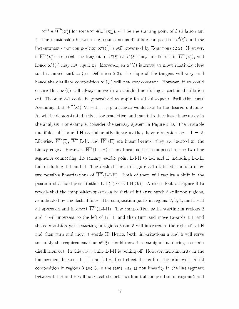
xp�� � Wu�x�j� for some x�j � �u�x�m�� will be the starting point of distillation cut
�� The relationship between the instantaneous distillate composition xd���
� and the
instantaneous pot composition xp���
� is still governed by Equations ������ However�
if Wu�x�j� is curved� the tangent to xp��� at xp��
�
� may not lie within Wu�x�j�� and
hence xd���
� may not equal x�j � Moreover� as xp��� is forced to move relatively close
to this curved surface �see De�nition ���� the slope of the tangent will vary� and
hence the distillate composition xd���
� will not stay constant� However� if we could
ensure that xp��� will always move in a straight line during a certain distillation
cut� Theorem �� could be generalized to apply for all subsequent distillation cuts�
Assuming that Wu�x�e� �e � �� � � � � ep are linear would lead to the desired outcome�
As will be demonstrated� this is too restrictive� and may introduce large inaccuracy in
the analysis� For example� consider the ternary system in Figure ��a� The unstable
manifolds of L and IH are inherently linear as they have dimension nc � � � ��
Likewise� Wu�I�� W
u�LI�� and W
u�H� are linear because they are located on the
binary edges� However� Wu�LIH� is not linear as it is composed of the two line
segments connecting the ternary saddle point LIH to LI and H including LIH�
but excluding LI and H� The dashed lines in Figure ��b labeled a and b show
two possible linearizations of Wu�LIH�� Both of them will require a shift in the
position of a �xed point �either LI �a� or LIH �b��� A closer look at Figure ��a
reveals that the composition space can be divided into �ve batch distillation regions�
as indicated by the dashed lines� The composition paths in regions �� �� �� and � will
all approach and intersect Wu�LIH�� The composition paths starting in regions �
and � will intersect to the left of LIH and then turn and move towards LI� and
the composition paths starting in regions � and � will intersect to the right of LIH
and then turn and move towards H� Hence� both linearizations a and b will serve
to satisfy the requirement that xp��� should move in a straight line during a certain
distillation cut� In this case� while LIH is boiling o� However� nonlinearity in the
line segment between LIH and LI will not eect the path of the orbit with initial
composition in regions � and �� in the same way as nonlinearity in the line segment
between LIH and H will not eect the orbit with initial composition in regions � and
��

�� A third linearization of Wu�LIH� may therefore be considered where the two line
segments between LIH and LI� and LIH and H are linearized separately �labeled
c in Figure ��b��
TBHH,TB
II,
TBLL,
TBI-H
TBL-I
TBL-I-H
•
1
2
3
45
•
•
a) b)
TBHH,TB
II,
TBLL,
TBL-I
TBL-I-H
•
•
•
a
b
c
•
•
TBI-H
Figure ��� Linearization of Wu�x�� to ensure that the pot composition will move
in a straight line during a certain distillation cut�
In conclusion� it has been found that PCB�x�j� can be divided into one or more
domains� termed pot composition boundaries�
De nition �� A pot composition boundary is the set of compositions that lead
to the same sequence of product cuts "P � fpk��pk�� � � �g upon distillation under
the limiting conditions of very high re�ux ratio and large number of trays� The pot
composition boundaries are subsets of the respective unstable manifolds of PCB�pk�
where pk represents the composition of cut k�
We can now proceed to generalize Theorem ���
Theorem �� Distillation cut k starting with pot composition xp�k�� � Wu�x�j� will
at limiting conditions of very high re�ux and large number of trays� and with linear
pot composition boundaries have a distillate composition xd�k close to x�j as long as
pot composition xp��� � Wu�x�j��
Proof� At very high re�ux xp���
� and xd���
� are located on the same residue curve�
Thus� xd���
� � Wu�x�j�� Furthermore� xd��
�
� lies on the tangent to xp��� through
�

xp���
�� The assumption of linear pot composition boundaries ensures that the tangent
lies within Wu�x�j�� Combined with the assumption of large number of trays this
ensures that xd���
� stays constant at the �limit set of xp���
�� i�e�� x�j � �
Of course� if xp�k�� � x�j then xp��� � xd�k � x�j as � � ���
Corollary �� If batch distillation region B�P� gives rise to the product sequence
P � fp��p�� � � �g� then at limiting conditions B�P� is the set of composition points "x �
Wu�p�� such that the resulting pot composition path xp��� will intersectW
u�pk� �pk �
P as � � ��� Composition points that give rise to a subset of P form the batch
distillation boundaries of B�P��
Corollary �� The pot composition boundary for product cut k is at limiting con�
ditions the set of composition points "x � PCB�pk� such that the subsequent pot com�
position path will intersect Wu�pl� �pl � "P � fpk��pk�� � � � � g � P as � � ���
where P is the product sequence for a particular batch distillation region� Thus� as�
suming linear pot composition boundaries is equivalent to assuming that the bound�
aries of a batch distillation region are linear�
Figure �� illustrates what would happen if the pot composition boundary was
curved� The initial reboiler composition xp�� � Wu�L�� and the �rst distillate com
position therefore will be equal to L according to Theorem ��� The pot composition
barrier for xp�� while in Wu�L�� PCB�L�� is equal to the separatrix connecting LI and
H including the endpoints� and in this case the pot composition boundary coincides
with PCB�L�� At the end of the �rst cut xp��� will intersect Wu�LI�� or so it ap
pears� However� the conditions that xp���
� and xd���
� lie on the same residue curve�
and xd���
� lies on the tangent to xp��� through xp���
� can only be satis�ed if xp���
remains in Wu�L�� The distillate will therefore take on compositions as indicated in
Figure ��� xp��� may move ever closer to Wu�LI�� but it will not intersect it� On
the other hand� if xp�� � Wu�I�� xp��� will necessarily have to intersect and cross
Wu�LI� in order to satisfy the same conditions� Note that this does not result in
crossing trajectories because xp��� is governed by Equations ������ while Wu�LI� is
governed by Equations ������ At that point xp��� will follow the same path as the
��

orbits starting on the convex side� As the temperature in the reboiler must increase
monotonically� xp��� must remain relatively close to Wu�LI� in both cases� This
behavior has been observed and discussed by several other authors �Ewell and Welch�
����� Van Dongen and Doherty� �� �b� Bernot et al�� ������
x p,0+L-I
•TB
L-I
TBLL,
TBHH,TB
II,
x p( ) +
•TB
L-I
x d( )
Figure ��� Ternary system with curved pot composition boundary�
��� The Product Sequence
As stated in De�nition ��� any composition taken interior to a speci�c batch distilla
tion region will always result in the same sequence of product cuts� It is demonstrated
here that� subject to the assumptions at the beginning of this chapter� the number of
cuts can be predicted a priori�
Theorem �� At very high re�ux� large number of trays� and with linear pot com�
position boundaries� an nc component mixture located interior to a batch distillation
region will produce exactly nc product cuts�
Proof� By de�nition� initial composition xp�� interior to B�P� will always result in
the same sequence of cuts P � fp��p��p�� � � �g� Following Theorem �� the pot
composition path xp��� will move in Wu�p�� until it intersects W
u�p�� � PCB�p���
then it will continue in Wu�p�� until it intersects W
u�p�� � PCB�p�� �PCB�p��� etc�
��
Initially� xp��� is free to move in the hyperplane de�ned byPnc
i� xi � �� However� the
number of degrees of freedom is reduced by one each time a pot composition barrier
is encountered� until xp��� moves in a �xed point in the composition space� Thus�
this point �azeotrope or pure component� is the �nal value of the pot composition�
Hence� the number of product cuts including the �nal composition left in the pot is
equal to the number of pure components in the initial mixture� We can conclude from
this exercise that the distillate path consists of exactly nc vertices� �
Corollary �� Following Corollary ��� an nc component mixture located on the
boundary of a batch distillation region will at very high re�ux� large number of trays�
and with linear pot composition boundaries produce at most nc� � product cuts�
The nc product cuts form a string of nc �xed points where each consecutive �xed
point has a higher boiling temperature then the previous �xed point� The �rst �xed
point is always an unstable node �p��� the intermediate �xed points are saddle points�
and the last �xed point will be either a saddle point or a stable node� The distillate
curve for the separation is the set of these points�
De nition �� �Hocking and Young� �� Let A � fa�� a�� � � � � akg be a set of k��
pointwise independent points in Rnc� The geometric k�simplex in Rnc determined by
A is the set of all points of the hyperplane Hk containing A for which the barycentric
coordinates with respect to A are all nonnegative� The barycentric coordinates of
a vector h with respect to A are the real numbers f�� f�� � � � � fk if and only if �i�
h �Pk
i� fiai and �ii�Pk
i� fi � �� ai is the vector from the origin to the point ai�
Theorem �� The nc vertices representing product cuts bound an �nc����simplex�
Proof� The composition simplex for an nc component system is an �nc� ��simplex
de�ned by the nc pure component �xed points on the hyperplane Hnc�� described
byPnc
i� xi � �� Any composition xp�� located in batch distillation region B�P� will
produce the set of product cuts P� fp�� � � � �pnc��g� The vertices are necessarily
pointwise independent� as the dimensionality is reduced by one every time a new pot
��

composition boundary is encountered and a new product cut is produced �a set of
vertices would be pointwise dependent if and only if the dimensionality remained the
same even after a vertex has been exhausted�� A vector h through any composition "x
lying in the interior of P will have positive barycentric coordinates that sum to unity
as they would represent the fractions of a mixture with composition "x that would be
recovered in each product cut� Hence� P bounds an �nc� ��simplex� which we will
term the product simplex �nc� �
It is evident that any point in B�P� must be a point in �nc� However� the converse
is not necessarily true� The residue curve map in Figure �� has three batch distillation
regions� and hence three product simplices� Product simplex ��� is bounded by the
pure components L� I� and maximum boiling binary azeotrope IH� product simplex
��� is bounded by L� IH� and ternary azeotrope LIH� and product simplex ��
� is
bounded by L� H� and IH� ��� and ��
� intersect� and hence a reboiler composition xp��
interior to ��� will in fact produce positive barycentric coordinates for both product
sets� However� the correct product sequence is fL�IH�LIHg� Therefore� xp�� is truly
located in batch distillation region B�� On the other hand� a composition located in
batch distillation region B� �bounded by the straight lines connecting L� I� IH� and L
IH� will only produce positive barycentric coordinates for this region� The product
sequence will be fL�I�IHg� Hence� region B� is an exception where the simplex
bounded by the product compositions does not coincide with the batch distillation
region itself� Therefore� a batch distillation region may not be a simplex� However�
from the above properties� each batch distillation region can be characterized by a
product simplex�
From the properties of simplices the result implies that any subset of the vertices
of P is itself the set of vertices for a geometric simplex �Hocking and Young� ������
Each such subsimplex is called a face of the product simplex� In particular� the
subsets of nc� � vertices are the highest order faces �facets�� There exist nc� � such
facets� These will be termed product simplex facets and are �nc � ��simplices� The
product simplex facet de�ned by the points p��p� � � � �pnc�� will be termed a product
simplex boundary� A product simplex boundary does not necessarily coincide with a
��

TBHH,TB
II,
TBLL,
TBI-H
•
•
TBL-I-H
1
2
3
TBHH,TB
II,
TBLL,
TBI-H
•
•
TBL-I-H
a) b)
Figure ��� Intersecting product simplices� The order of boiling temperatures�TL�mB � TI�n
B � TH�nB � TL�I�n
B � TL�I�H�qB �
pot composition boundary� in the same way product simplices and batch distillation
regions do not necessarily coincide� A product simplex boundary can be found by
removing the unstable node from the set describing the product simplex� Conversely�
a product simplex is an �nc � ��simplex de�ned by a set of nc �xed points� where
nc�� points form a product simplex boundary and the remaining point is the unstable
node in the set�
Theorem �� Let P represent the set of product cuts achievable� and pk a product
cut in P� Then PCB�pk� � PCB�pl� �l � �� � � � � k � � and �k � �� � � � � nc� ��
Proof� Let xp��� represent the pot composition orbit and xd��� the corresponding
distillate composition orbit related through the set of dierential equations ������
Furthermore� let xp�k be the pot composition at the beginning of product cut pk�
xp�k� xp�k�� etc�� are points on xp���� while pk� pk�� etc�� are points on xd���� xp�k �
PCB�pk���� xp�k� � PCB�pk�� etc� If the theorem is not true� this implies that initial
condition xp�k� would result in a dierent distillate orbit than initial condition xp�k�
However� since xp�k and xp�k� lie on the same orbit� this is infeasible� Therefore
xp�k� must also be in PCB�pk���� �
Corollary �� It follows from Theorem ��� that pk � �u�pl� �l � �� � � � � k � ��
��

��� Relaxing Limiting Assumptions
The theory for multicomponent homogeneous batch distillation is derived based on
the assumptions of very high re�ux ratio� large number of theoretical stages� and
linear pot composition boundaries� If any of these limiting conditions are relaxed� a
slight deviation from the predicted behavior may be observed�
Finite number of stages and re�ux ratio� if the assumptions of large number
of theoretical stages and very high re�ux ratio are relaxed� the column pro�le will
no longer follow a simple residue curve and the pot composition path will not move
in a straight line� but take on some curvature� Bernot et al� ������ demonstrate
that the pot and distillate paths can move slightly into another batch distillation
region� and one may get a small fraction of an additional product cut �nc � � cuts��
Nevertheless� the pot and distillate paths will have the same basic shape as before�
We have observed that the theory is still valid for columns with as little as � trays�
Curved pot composition boundaries� in the case of a highly curved pot com
position boundary the pot composition path will move along the boundary� while the
distillate path may move into another batch distillation region resulting in additional
product cuts �Van Dongen and Doherty� �� �b� Bernot et al�� ������
Holdup on trays� Watson et al� ������ study the distillation of quaternary com
ponent mixtures and claim that large holdup in the traysection and the condenser may
result in separation sequences other than the ones predicted by the theory� However�
large holdup in the column will only decrease the sharpness of splits� On the other
hand� the theory only applies to homogeneous systems� Watson and his coworkers ap
ply the theory to a heterogeneous mixture� which residue curve map is derived using
a vaporliquidliquid equilibrium model� In their simulations� performed to con�rm
their predictions� however� they used a vaporliquid equilibrium model� The results
therefore� not so surprisingly� were not consistent with the predictions�
��

�� Example� Quaternary System
To demonstrate the applications of the results derived in this chapter� the quaternary
system acetone �A�� chloroform �C�� ethanol �E�� and benzene �B� has been charac
terized using the new concepts� The �xed points of this system at � atm� were found
by Fidkowski et al� ������ and are shown in Table ���� The system features four
azeotropes� and its composition simplex is shown in Figure ���
Table ���� Compositions� boiling temperatures� and stability of �xed points for thesystem acetone �A�� chloroform �C�� ethanol �E�� and benzene �B� at � atm�
e A C E B TB�K� TypeA � � � � ������ un
CE � �� ��� ������ � ����� unC � � � � ������ s
ACE ���� � ������ ������ � ������ sAC ������ ������ � � �� ��� sEB � � ������ ���� � ����� sE � � � � ������ snB � � � � ������ sn
A and the binary azeotrope CE are both unstable nodes� and their unstable man
ifolds �ll most of the composition space� Wu�A� includes all the compositions above
the shaded area in Figure ��a including the point A itself but excluding the shaded
area and the �xed points located on it� Similarly� Wu�CE� includes the composi
tions below the shaded area including CE� but excluding the shaded area and all the
compositions not involving E� while Ws�A� � W
s�CE�� � W
u�C� includes all the
compositions not involving E below the unstable separatrix connecting AC and B�
while Ws�C� includes the binary compositions between CE and C excluding CE and
C� Wu�AC� includes the compositions along the stable separatrix connecting AC and
B excluding B� while Ws�AC� includes all the compositions not involving B to the
left of the unstable separatrices between A and ACE� and CE and ACE excluding
the �xed points and the binary edge between CE and C� Wu�ACE� includes all the
compositions on the shaded area in Figure ��a excluding the edges between AC and
��

A
C E
B
• •
•
•EB
ACE
CE
b)
AC
A
C E
B
• •
•
•EB
ACE
CE
a)
AC
Figure ��� The composition simplex for acetone� chloroform� ethanol� and benzene�a� Shaded area separates W
u�A� and W
u�CE�� b� Shaded area separates W
s�E� and
Ws�B��
B� and E and B� Ws�ACE� includes the compositions along the two unstable sep
aratrices connecting the ternary azeotrope to A and CE excluding the �xed points�
Wu�EB� includes the entire binary edge between E and B excluding the pure com
ponents� while Ws�EB� includes the entire shaded area in Figure ��b excluding the
�xed points and the unstable separatrices between A and ACE� and CE and ACE�
Finally� Wu�E� � fEg� and W
u�B� � fBg� W
s�E� includes all the compositions to
the right of the shaded area in Figure ��b excluding the �xed points� while Ws�B�
includes all the compositions to the left of the shaded area in Figure ��b excluding
all compositions not involving B and the �xed points�
When the unstable and stable manifolds are established� we can determine the
boundary limit sets from De�nition ��� �u and �s are presented in Table ����
We now proceed to determine the pot composition boundaries for the two unstable
nodes� Application of Equation ����� leads to Equations ��� � and ������ Hence
PCB�A� is equal to the shaded area in Figure ��a including the �xed points� while
PCB�CE� is equal to PCB�A� plus the compositions below the stable separatrix
��
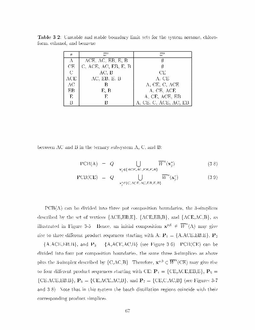
Table ���� Unstable and stable boundary limit sets for the system acetone� chloroform� ethanol� and benzene�
e �u �s
A ACE� AC� EB� E� B CE C� ACE� AC� EB� E� B C AC� B CE
ACE AC� EB� E� B A� CEAC B A� CE� C� ACEEB E� B A� CE� ACEE E A� CE� ACE� EBB B A� CE� C� ACE� AC� EB
between AC and B in the ternary subsystem A� C� and B�
PCB�A� � Q ��
x�
j�fACE�AC�EB�E�Bg
Wu�x�j� ��� �
PCB�CE� � Q ��
x�
j�fC�ACE�AC�EB�E�Bg
Wu�x�j� �����
PCB�A� can be divided into three pot composition boundaries� the �simplices
described by the set of vertices fACE�EB�Eg� fACE�EB�Bg� and fACE�AC�Bg� as
illustrated in Figure ��� Hence� an initial composition xp�� � Wu�A� may give
rise to three dierent product sequences starting with A� P� � fA�ACE�EB�Eg� P�
� fA�ACE�EB�Bg� and P� � fA�ACE�AC�Bg �see Figure ���� PCB�CE� can be
divided into four pot composition boundaries� the same three �simplices as above
plus the �simplex described by fC�AC�Bg� Therefore� xp�� � Wu�CE� may give rise
to four dierent product sequences starting with CE� P� � fCE�ACE�EB�Eg� P� �
fCE�ACE�EB�Bg� P� � fCE�ACE�AC�Bg� and P� � fCE�C�AC�Bg �see Figures ��
and � �� Note that in this system the batch distillation regions coincide with their
corresponding product simplices�
��

A
C E
B
• •
•
•EB
ACE
CE
AC
Figure ��� Pot composition boundaries�
�� Summary
In this chapter the theory of residue curves maps for analysis of batch distillation
of homogeneous mixtures has been generalized to homogeneous systems with an ar
bitrary number of components� The following properties for simple distillation have
been demonstrated�
� The whole composition simplex can be de�ned in terms of the respective disjoint
unstable manifolds of the �xed points� Q �Sepe�W
u�x�e� �
Sunm�W
u�x�m� Ss
n�Wu�x�n�
Ssnq�W
u�x�q��
� Each �xed point can be characterized by its unstable and stable boundary limit
sets� �u�x�� and �s�x��� respectively�
Moreover� based on the limiting assumptions of very high re�ux ratio� large num
ber of trays� linear pot composition boundaries� and a recti�er con�guration� proper
ties of the batch distillation composition simplex have been introduced�
� The movement of the pot composition orbit will be constrained by pot composi�
tion barriers present in the composition simplex� If xp��� � Wu�x��� the unsta
�
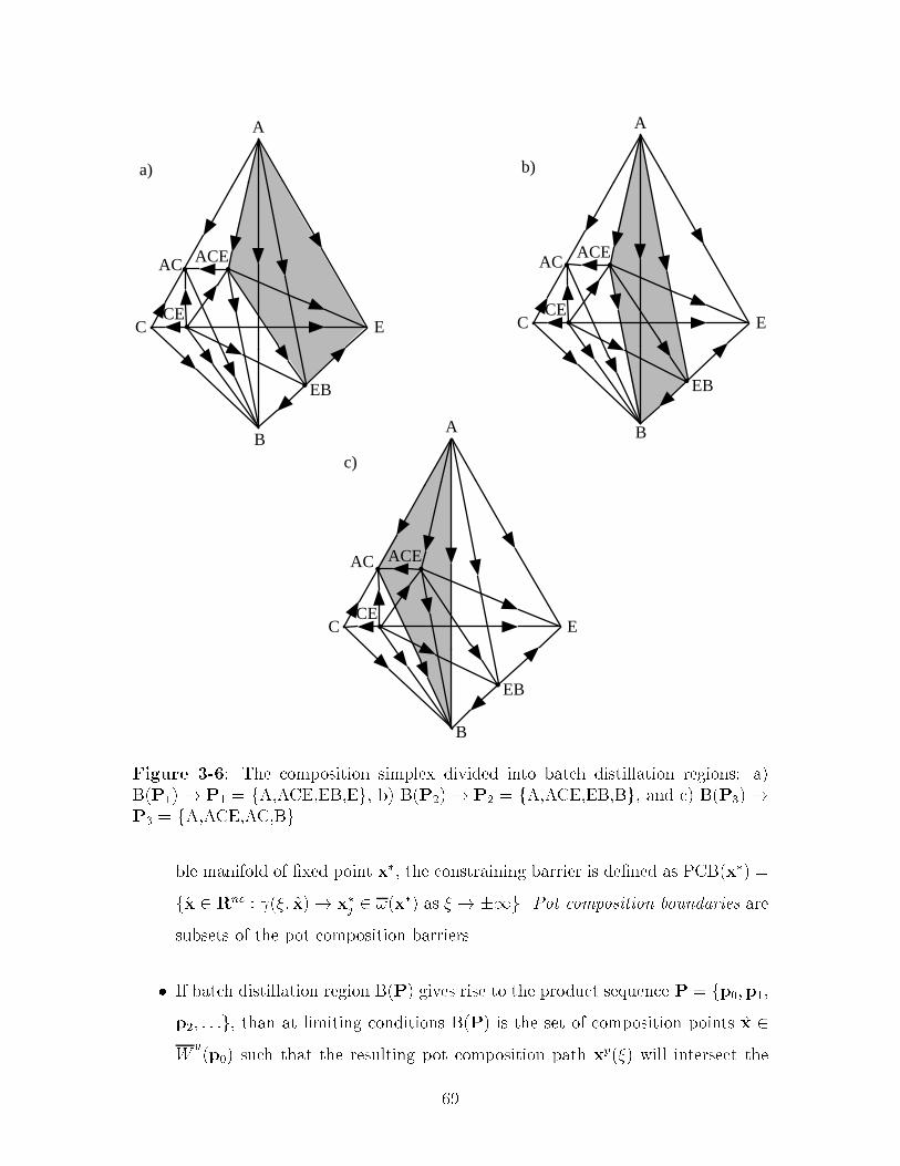
A
C E
B
• •
•
•EB
ACE
CE
AC
c)
A
C E
• •
•
•EB
ACE
CE
AC
B
b)
A
C E
B
• •
•
•EB
ACE
CE
AC
a)
Figure ��� The composition simplex divided into batch distillation regions� a�B�P�� � P� � fA�ACE�EB�Eg� b� B�P�� � P� � fA�ACE�EB�Bg� and c� B�P�� �P� � fA�ACE�AC�Bg�
ble manifold of �xed point x�� the constraining barrier is de�ned as PCB�x�� �
f"x � Rnc � ��� "x� � x�j � ��x�� as � � ��g� Pot composition boundaries are
subsets of the pot composition barriers�
� If batch distillation region B�P� gives rise to the product sequence P � fp��p��
p�� � � �g� than at limiting conditions B�P� is the set of composition points "x �
Wu�p�� such that the resulting pot composition path xp��� will intersect the
��

A
C E
B
• •
•
•EB
ACE
CE
b)
AC
A
C E
B
• •
•
•EB
ACE
CE
a)
AC
Figure ��� The composition simplex divided into batch distillation regions� a�B�P�� � P� �fCE�ACE�EB�Eg� and b� B�P�� � P� �fCE�ACE�EB�Bg�
A
C E
B
• •
•
•EB
ACE
CE
a)
AC
A
C E
B
• •
•
•EB
ACE
CE
b)
AC
Figure �� The composition simplex divided into batch distillation regions� a�B�P�� � P� �fCE�ACE�AC�Bg� and b� B�P�� � P� �fCE�C�AC�Bg�
unstable manifolds of pk� Wu�pk� �pk � P as � � ��� Composition points
that give rise to a subset of P form the batch distillation boundaries of B�P��
� An initial composition xp�� located interior to batch distillation region B at
limiting conditions will give rise to exactly nc product cuts� and these nc cuts
��

form an nc product simplex�
� A batch distillation region and its corresponding product simplex de�ned by
the the nc �xed points in P � fp�� � � � �pnc��g do not necessarily coincide�
The derived properties will allow complete characterization of the structure of the
composition space for a multicomponent system when using batch distillation based
only on the information of the compositions� boiling temperatures� and the stability of
the �xed points� The composition space of the quaternary system acetone� chloroform�
ethanol� and benzene has been characterized using the derived properties�
��

��

Chapter �
Characterization of the Batch
Distillation Composition Simplex
Chapters � and � explore the structure imposed on the composition simplex �residue
curve map� of a multicomponent system describing batch distillation by the presence
of azeotropes� This structure can be visualized by dividing the composition simplex
�regular simplex� into a series of distinct batch distillation regions� All initial com
positions within a particular batch distillation region will result in the same sequence
of product cuts� and these cuts will have compositions close to pure components or
azeotropes� Each batch distillation region can therefore be characterized by a product
simplex� In this chapter an algorithm for constructing the batch distillation compo�
sition simplex is described based on the theoretical results developed in Chapter ��
The algorithm is based solely on information about the individual �xed points �pure
components and azeotropes�� i�e�� composition� boiling temperature� and nature of
point �unstable or stable node� or saddle point�� In particular� no numerical integra
tion is required� The algorithm assumes high re�ux ratio� large number of trays� and
linear pot composition boundaries� Furthermore� it is assumed that a single batch
distillation column with a recti�er con�guration is employed� Other studies on batch
distillation have proposed more sophisticated column con�gurations� Bernot et al�
������ demonstrate that a stripper con�guration may reduce the number of cuts if
the stable separatrix is highly curved� Davidyan et al� ������ and Safrit et al� ������
��
propose a batch distillation column consisting of a stripper section� a recti�er sec
tion� and a vessel in between� With the latter con�guration material is taken o
both as top and bottom products� Skogestad et al� ������ discuss the bene�ts of a
multivessel con�guration� Ultimately� the presented methodology can be extended
to include a set of speci�c rules associated with each alternative technology� These
rules can then be applied automatically for each relevant technology to generate more
separation alternatives for the engineer� For example� the algorithm presented here
can be applied directly to a stripper con�guration under the same limiting conditions
simply by reversing time in the governing dierential equations as demonstrated in
Appendix A�
��� Constructing the Composition Simplex
For binary� ternary� and even quaternary systems the structure of the composition
simplex �residue curve map� can be extracted through relatively straightforward ex
periments� or through integration of the system of dierential equations describing
simple distillation and sampling a representative number of trajectories� However�
for systems with more than four components this approach is neither feasible nor
practical� Therefore� a general� less elaborate procedure for describing the composi
tion simplex for a multicomponent system is desired� For instance� exhaustive search
algorithms have been developed for continuous distillation of systems exhibiting only
binary azeotropes �Sera�mov et al�� ����� Petlyuk et al�� ����a� Petlyuk et al�� ����b�
Petlyuk et al�� ������ Matsuyama and Nishimura ������ and Doherty and Calderola
��� �� classify all possible ternary residue curve maps� Knight and Doherty ��� ��
present a graphtheoretic representation of the boundary structure for general ternary
systems� An improved algorithm for ternary systems is described by Foucher et al�
������� Malenko �����a� ����b� ����c� proposes a graphical approach for isolat
ing regions of ideal fractionation for multicomponent systems based on the search
for maximumtemperature hypersurfaces representing divisions in the composition
simplex� Bernot et al� ������ introduce a set of rules for placing batch distillation
��

boundaries in a ternary system provided that the simple residue curve map is known
beforehand� Ahmad and Barton ������ propose an algorithm for �nding the batch
distillation regions for multicomponent systems by systematically generating all sub
systems starting with ternary systems� Safrit and Westerberg ������ present an
expanded algorithm based on the same evolutionary approach�
There are a number of de�ciencies in the approaches described in the existing
literature� In particular� �� it is not possible to characterize the composition simplex
for all possible con�gurations only from information about each �xed point� as pointed
out by Foucher et al� ������� even for ternary systems� �� not all possible topological
con�gurations are taken into account �some of the exceptions are pointed out in
Chapter ��� and �� a batch distillation region may not necessarily coincide with its
characteristic product simplex as discussed in Chapter �� Our algorithm accounts for
all possible con�gurations subject to some relatively mild assumptions�
Chapter � demonstrates that the composition simplex of a system can be com
pletely characterized by knowing the boundary limit sets of each �xed point in the
system� The completed boundary limit sets will accurately represent the topological
structure of the composition simplex� and also make it possible to extract all product
sequences achievable when applying batch distillation� In this work characterizing of
the composition simplex is accomplished through completion of the boundary limit
sets� The methodology for generating the unstable boundary limit sets is presented�
but by reversing time the exact same methodology can be applied to generating the
stable boundary limit sets� The methodology is guaranteed to �nd the correct bound
ary limit sets for all �xed points in the system provided that the system is globally
determined� A system is globally undetermined if topological requirements for the
composition simplex given by the compositions� boiling temperatures� and stability
of each �xed point can be met by more than one combination of boundary limit sets�
In Section ����� it is demonstrated that this may occur if the number of unstable
nodes is two and the number of stable nodes is greater than two� and vice versa� In
such cases integration of the equations governing simple distillation is necessary to
determine the correct boundary limit sets� The dierent steps of the algorithm for
��

constructing the composition simplex are shown in Figure ���
Find azeotropes
Pure component data V-L-E model
Complete unstableboundary limit sets
Binary parameters
Components to beseparated
Enumerateproduct sequences
Composition Simplex
Figure ��� Algorithm for constructing the composition simplex�
����� Predicting the Azeotropes
First the azeotropes of the system of interest are predicted� A suitable vaporliquid
equilibrium model is chosen and the necessary data is gathered to compute the
temperatures and compositions of all the azeotropes� The pure components and
azeotropes are exactly the �xed points of the dierential equations describing simple
distillation �Equations ������� The azeotropes can therefore be found by formulating
a multidimensional root�nding problem� and solving for all physically valid roots�
For example� a homotopy method combined with arc length continuation� restricted
to those systems not exhibiting multiple azeotropy� is proposed by Fidkowski et al�
������� Similarly� the global optimization based approach by Maranas et al� ������
is applicable to a limited class of vaporliquid equilibrium models� Vaporliquid equi
librium calculations rely on accurate binary interaction parameters� and missing or
inadequate data �as well as limitations of the vaporliquid equilibrium model of choice�
��
can undermine the accuracy of these predictions� Unfortunately� complete equilibrium
data for the system of interest are often not available� Usually� however� some other
type of data can be located readily� Twu and Coon ������ and Carlson ������ pro
vide techniques and guidelines on how to accurately perform vaporliquid equilibrium
calculations in such cases�
Doherty and Perkins ������ conclude that the only type of �xed points which
can occur are� unstable and stable nodes� saddle points� and armchairlike points�
The three �rst types are elementary �xed points� while the latter type is a non
elementary �xed point� The stability of the �xed points can be found by performing
a linear stability analysis around each �xed point �Fidkowski et al�� ������ Non
elementary �xed points will have one or more eigenvalues equal to zero� and may
correspond to bifurcation points with respect to a parameter� i�e�� the global structure
changes from one type to another �see� for example� Knapp �������� The bifurcation
parameter is usually pressure� but it could also be a model parameter� etc� Although
it is possible that a column is operating at the bifurcation pressure� and hence that
the calculations will predict one or more nonelementary �xed point� it is not very
likely� The algorithm therefore assumes elementary �xed points� In that case the
eigenvalues of the linearized system in the neighborhood of a �xed point must be real
and nonzero� and the �xed points have the properties of nodes or saddles� A system
of nc components will exhibit nc � � real valued eigenvalues for each �xed point� A
stable �unstable� node has only negative �positive� eigenvalues� while a saddle point
has some negative and some positive eigenvalues� A test must be applied to the �xed
points predicted to establish that the data is topologically consistent �Fidkowski et
al�� ������
����� Dividing Boundaries
The eigenvectors de�ned by the positive eigenvalues and the eigenvectors de�ned by
the negative eigenvalues span the unstable eigenspace and the stable eigenspace� re
spectively� of the linearized system in the neighborhood of a particular �xed point�
The unstable and stable manifolds of the nonlinear system will have the same dimen
��

sions as those of the eigenspaces of the linearized system� and the eigenvectors will be
tangent to the manifolds through the �xed point �Guckenheimer and Holmes� �� ���
The unstable �stable� manifold of an unstable �stable� node therefore has dimension
nc � �� while the stable �unstable� manifold has zero dimension� The unstable and
stable manifolds of a �xed point are de�ned in Chapter ��
In a system containing two unstable nodes an nc�� dimensional hypersurface must
separate their unstable manifolds� Likewise� if there are two stable nodes present an
nc� � dimensional hypersurface must separate their stable manifolds� Such a surface
separating the unstable manifolds of two unstable nodes is termed a stable dividing
boundary and is denoted by SDB�x�ma�x�mb
�� where x�maand x�mb
are unstable nodes�
A surface separating the stable manifolds of two stable nodes is termed an unstable
dividing boundary and is denoted by UDB�x�qa�x�qb
�� where x�qa and x�qb are stable
nodes� For example� in a binary system a dividing boundary is just a point and
has dimension zero� in a ternary system a dividing boundary consists of one or more
connected line segments and has dimension �� etc� A simple distillation trajectory
through a composition point on the boundary will remain on the boundary both as
� � �� and � � ��� � denotes a dimensionless measure of time� SDB�x�ma�x�mb
�
and UDB�x�qa�x�qb
� are de�ned formally by Equations ����� and ������ where ��� "x� is
the simple distillation orbit through "x�
SDB�x�ma�x�mb
� f"x � Rnc � ��� "x� � x� � �uc�x�ma�x�mb
� as � � ��g �����
UDB�x�qa�x�qb
� f"x � Rnc � ��� "x� � x� � �sc�x�qa�x�qb
� as � � ��g �����
The common unstable boundary limit set of x�maand x�mb
� �uc�x�ma�x�mb
�� and the com�
mon stable boundary limit set of x�qa and x�qb � �sc�x�qa�x
�qb
�� are de�ned by Equations
����� and ������
�uc�x�ma�x�mb
� �u�x�ma� � �u�x�mb
� �����
�sc�x�qa�x�qb
� �s�x�qa� � �s�x�qb� �����
�
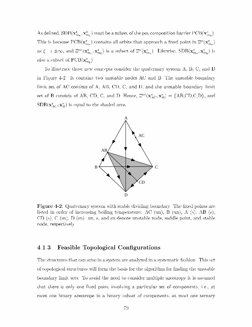
As de�ned� SDB�x�ma�x�mb
� must be a subset of the pot composition barrier PCB�x�ma��
This is because PCB�x�ma� contains all orbits that approach a �xed point in �u�x�ma
�
as � � ��� and �uc�x�ma�x�mb
� is a subset of �u�x�ma�� Likewise� SDB�x�ma
�x�mb� is
also a subset of PCB�x�mb��
To illustrate these new concepts consider the quaternary system A� B� C� and D
in Figure ��� It contains two unstable nodes AC and B� The unstable boundary
limit set of AC consists of A� AB� CD� C� and D� and the unstable boundary limit
set of B consists of AB� CD� C� and D� Hence� �uc�x�AC �x�B� � fAB�CD�C�Dg� and
SDB�x�AC �x�B� is equal to the shaded area�
•
•
AB
D
C
CD
A
B
AC•
Figure ��� Quaternary system with stable dividing boundary� The �xed points arelisted in order of increasing boiling temperature� AC �un�� B �un�� A �s�� AB �s��CD �s�� C �sn�� D �sn�� un� s� and sn denote unstable node� saddle point� and stablenode� respectively�
����� Feasible Topological Con�gurations
The structures that can arise in a system are analyzed in a systematic fashion� This set
of topological structures will form the basis for the algorithm for �nding the unstable
boundary limit sets� To avoid the need to consider multiple azeotropy it is assumed
that there is only one �xed point involving a particular set of components� i�e�� at
most one binary azeotrope in a binary subset of components� at most one ternary
��

azeotrope in a ternary subset of components� etc� It is also assumed that a system
involves at least two components� The latter assumption is included because it makes
little sense to analyze a system of one component� The systems are characterized by
the number of unstable and stable nodes� whether there is an azeotrope involving all
components� and the stability of this azeotrope�
Theorem �� If a system has only one unstable node� the unstable node�s unstable
boundary limit set will contain all the other �xed points in the system�
Proof� Let Wu�x�m� be the unstable manifold of the unstable node x�m� W
u�x�m�
has dimension nc� �� while any other unstable manifold in the composition simplex
has at most dimension nc� �� Any neighborhood of a �xed point x� must therefore
intersect at least one orbit that approaches the unstable node as � � ��� Hence�
x� is a limit point of Wu�x�m�� If x� is not the unstable node itself it follows from
De�nition �� that x� must be in the unstable boundary limit set of x�m� �
Theorem �� A saddle point involving all components cannot exist in an nc com�
ponent system with only one unstable node�
Proof� Assume that such a �xed point x� exists� and that the unstable node is located
on one of the facets� x� is then located internal to the unstable node s unstable
manifold� Only isolated �xed points may exist in the composition space �Doherty
and Perkins� ������ Let R be a neighborhood of x�� By Theorem �� x� is a limit
point of the unstable node s unstable manifold� Orbits intersecting the boundary of
R will therefore all point inwards� Since all orbits approach a �xed point as � � ��
R must contain a stable node� but this contradicts the assumption that R contains a
saddle point� �
Corollary �� It follows from Theorem ��� that an azeotrope involving all compo�
nents in an nc component system with only one unstable node located on one of the
facets must be a stable node�
�

By similar reasoning� it is evident that if a system has only one stable node� and
the stable node is located on one of the facets� a �xed point involving all components
must be an unstable node� We can also conclude that for a system to contain a saddle
point involving all components the system must feature at least two unstable and two
stable nodes� The ternary system acetone� chloroform� and methanol shown in Figure
��� is an example of such a system� In fact� a ternary system with two unstable and
two stable nodes will always feature a ternary saddle point�
Theorem � Assume that an nc component system features two unstable nodes�
two stable nodes� and a saddle point involving all the components� Then the saddle
point must be in the unstable boundary limit sets of both unstable nodes� and in the
stable boundary limit sets of both stable nodes�
Proof� Assume that a �xed point x� involving all components exists and that the point
is an element of the unstable boundary limit set of only one of the unstable nodes�
x� must therefore be located internal to this unstable node s unstable manifold� By
Theorem �� and Corollary �� this makes x� a stable node� Similarly� if the point
is an element of the stable boundary limit set of only one stable node x� must be
unstable� The only possible explanation is that x� is a limit point of both unstable
nodes unstable manifolds and both stable nodes stable manifolds� �
Corollary �� It follows from Theorem ��� that an nc saddle point must lie in the
intersection between the stable and the unstable dividing boundary�
Theorem �� If a system contains three or more unstable nodes� two stable nodes�
and a saddle point involving all components the system is globally undetermined�
Proof� From Theorem � it follows that the saddle point must be an element of the
unstable boundary limit sets of at least two unstable nodes and an element of the
stable boundary limit sets of at least two stable nodes� With three unstable nodes
several possible combinations exist� Hence� there is insu�cient information available
to determine the unstable boundary limit sets of the system uniquely� �
�
Similarly� it is evident that a system which exhibits two unstable nodes� three or
more stable nodes� and a saddle point involving all components is globally undeter
mined�
The results derived in Theorems �� to �� are consistent with earlier work on
ternary systems� Foucher et al� ������ demonstrate by using a consistent topology
test that if the sum of binary azeotropes �saddles and nodes� and pure component
nodes is equal to six for a ternary system containing a ternary saddle point the system
is globally undetermined� A ternary saddle point in a ternary system has exactly two
orbits approaching as � � �� and exactly two orbits approaching as � � ���
Foucher et al� ������ demonstrate that these special orbits may either approach pure
component nodes or binary azeotropes �saddles and nodes� as � � �� and ���
In other words� there exists exactly four orbits connecting the ternary saddle point
to either pure component nodes or binary azeotropes� A necessary condition for the
existence of a ternary saddle point in a ternary system is therefore that the sum of
pure component nodes and binary azeotropes �saddles and nodes� must be greater
or equal to four� Only if the sum of binary azeotropes �saddles and nodes� and pure
component nodes is equal to four a unique solution exists�
The consistent topology test for ternary systems used by Foucher et al� ������
is derived by Doherty and Perkins ������� The set of restrictions imposed on the
complexity of the ternary system can be written as�
�N� � �S� � N� � S� � N� � � �����
N� � S� � � �����
N� � S� � � �����
N� � S� � � ��� �
where Ni refers to the number or nodes �unstable and stable� involving i components�
and Si refers to the number of saddle points involving i components� In a ternary
system with two unstable and two stable nodes� and a ternary saddle point� S� � ��
N� � �� and N� � N� � �� When inserting these values into Equation ����� we get
�

S� � �� i�e�� there may be no binary saddle points in the system� The ternary saddle
point must therefore be connected to nodes only� These nodes are exactly the two
unstable and two stable nodes� In conclusion� the criterion derived by Foucher et al�
������ is equivalent to requiring that for a ternary system containing a ternary saddle
point to be globally determined� it must contain exactly two unstable and two stable
nodes�
An example of a ternary system that is globally undetermined is shown in Figure
��� The system exhibits two unstable nodes �AB and AC�� three stable nodes �A�
B� and C�� and a ternary saddle point �ABC�� Also� the ternary system exhibits a
binary saddle point �BC�� Figure ��a shows one feasible topological structure that
satis�es the stability requirements of each �xed point� and Figure ��b shows another
feasible topological structure� As indicated� the unstable boundary limit sets for the
two con�gurations are dierent� A third topology is feasible where the binary saddle
point BC is connected to unstable node AC rather than AB� and ternary saddle point
ABC is connected to stable node B rather than C�
Although Theorem �� does not exclude the possibility of having a system with
three or more unstable nodes� two stable nodes �or vice versa�� and no nc component
saddle point� such characteristics can only be observed in systems with four or more
components� The nc component saddle point lies in the intersection between the
stable and the unstable dividing boundaries �Theorem ���� In a ternary system the
intersection is a point� and hence must be equal to a �xed point� In systems with
more than three components the intersection will have dimension greater or equal
to one� The existence of a saddle point in the intersection therefore depend on the
topological structure locally on the dividing boundaries� Experience shows that the
number of nodes in a system typically goes down rather than up as the number of
components increases� The algorithm will therefore be restricted to systems where
the system itself and all its subsystems exhibit at most two unstable and at most two
stable nodes� A �xed point that is a saddle point in the system itself may remain a
saddle point locally on a stable dividing boundary� or it may have the properties of an
unstable or stable node� Similarly� we must therefore require that a stable dividing
�
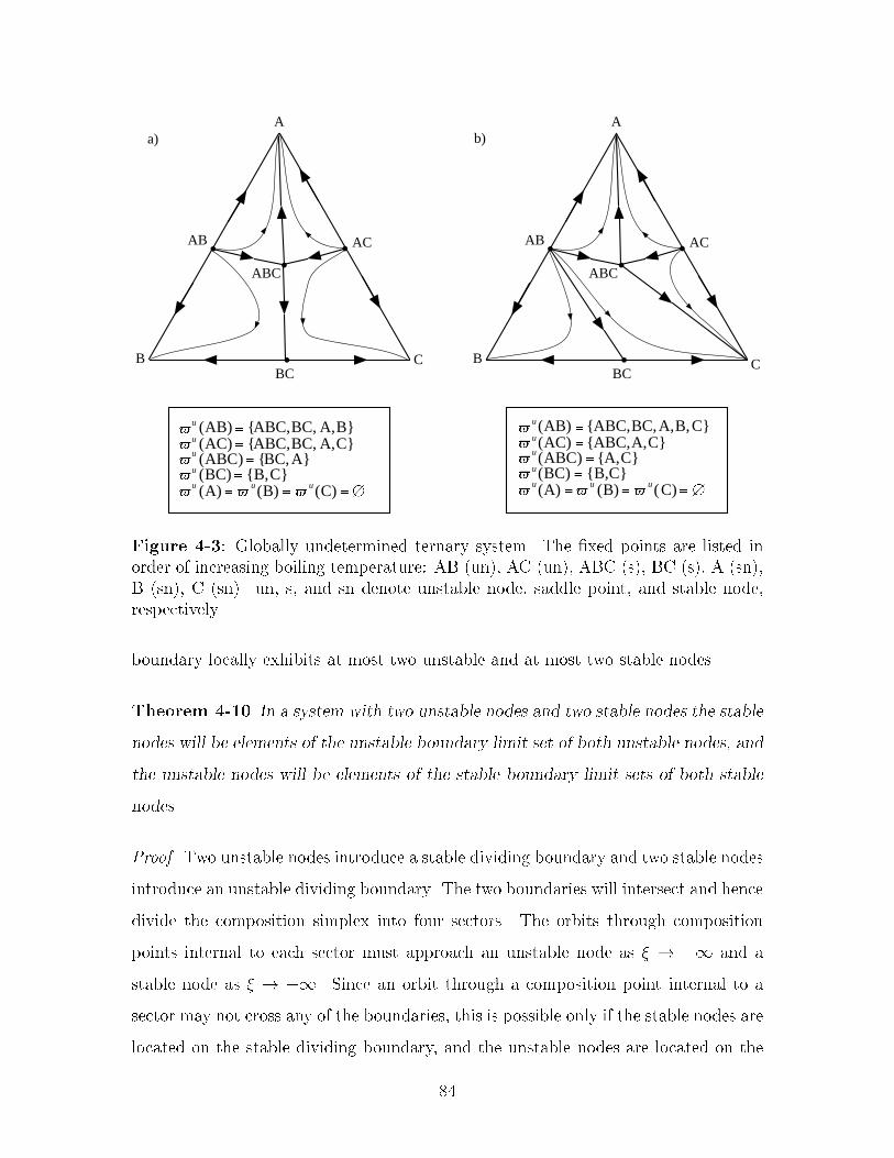
•
•
•
•
A
B C
ABC
AC
BC
AB
a)
•
•
•
•
A
B C
ABC
ACAB
BC
b)
u (AB) {ABC,BC, A,B}u (AC) {ABC,BC, A,C}u (ABC) {BC,A}u (BC) {B,C}u (A) u(B) u(C)
u(AB) {ABC,BC,A,B,C}u(AC) {ABC,A,C}u(ABC) {A,C}u(BC) {B,C}u(A) u (B) u(C)
Figure ��� Globally undetermined ternary system� The �xed points are listed inorder of increasing boiling temperature� AB �un�� AC �un�� ABC �s�� BC �s�� A �sn��B �sn�� C �sn�� un� s� and sn denote unstable node� saddle point� and stable node�respectively�
boundary locally exhibits at most two unstable and at most two stable nodes�
Theorem ��� In a system with two unstable nodes and two stable nodes the stable
nodes will be elements of the unstable boundary limit set of both unstable nodes� and
the unstable nodes will be elements of the stable boundary limit sets of both stable
nodes�
Proof� Two unstable nodes introduce a stable dividing boundary and two stable nodes
introduce an unstable dividing boundary� The two boundaries will intersect and hence
divide the composition simplex into four sectors� The orbits through composition
points internal to each sector must approach an unstable node as � � �� and a
stable node as � � ��� Since an orbit through a composition point internal to a
sector may not cross any of the boundaries� this is possible only if the stable nodes are
located on the stable dividing boundary� and the unstable nodes are located on the
�

unstable dividing boundary� The stable nodes are therefore in the common unstable
dividing boundary limit set� and hence elements of the unstable boundary limit sets
of both unstable nodes� Likewise� the unstable nodes must be in the common stable
boundary limit set� and hence the unstable nodes will be elements of the stable
boundary limit sets of both stable nodes� �
Theorem ��� Let x�mabe an unstable node and x�j an element in the unstable
boundary limit set of x�ma� Then if a system and all its subsystems can be character�
ized as having at most two unstable nodes and at most two stable nodes the unstable
boundary limit set of x�j is a subset of the unstable boundary limit set of x�ma�
Proof� It follows from Theorem �� that if x�mais the only unstable node the theorem
is always true� Also note that the theorem is true if x�j is a stable node since the
boundary limit set of a stable node is the empty set� Therefore it only remains to
prove that the theorem is true for the system and all its subsystems having two
unstable nodes� e�g�� x�maand x�mb
� and x�j being a saddle point�
The �xed points in the unstable boundary limit set of x�j � �u�x�j�� are limit points
of the unstable manifold to x�j � For the theorem to be true the �xed points in
�u�x�j� must also be limit points to the unstable manifold of x�ma�see De�nition
���� �u�x�ma� �u�x�mb
� contains all the �xed points in the system except the unsta
ble nodes themselves� Hence� if a �xed point in ��x�j� is not an element of �u�x�ma��
it must be an element of �u�x�mb�� Let x�j �� �uc�x�ma
�x�ma�� i�e�� x�j is not an element
of the common unstable boundary limit set� Then the limit points of the unstable
manifold of x�j will necessarily be a subset of the unstable boundary limit set of x�ma�
Otherwise at least one orbit in the unstable manifold of x�j would intersect the sta
ble dividing boundary and approach a �xed point on the other side of the boundary
as � � ��� Since orbits can only intersect the stable dividing boundary at �xed
points� this is infeasible� On the other hand� if the orbit approaches a �xed point on
the stable dividing boundary as � � ��� the theorem is true since the �xed points
on the stable dividing boundary are elements of the unstable boundary limit set of
x�ma�
�
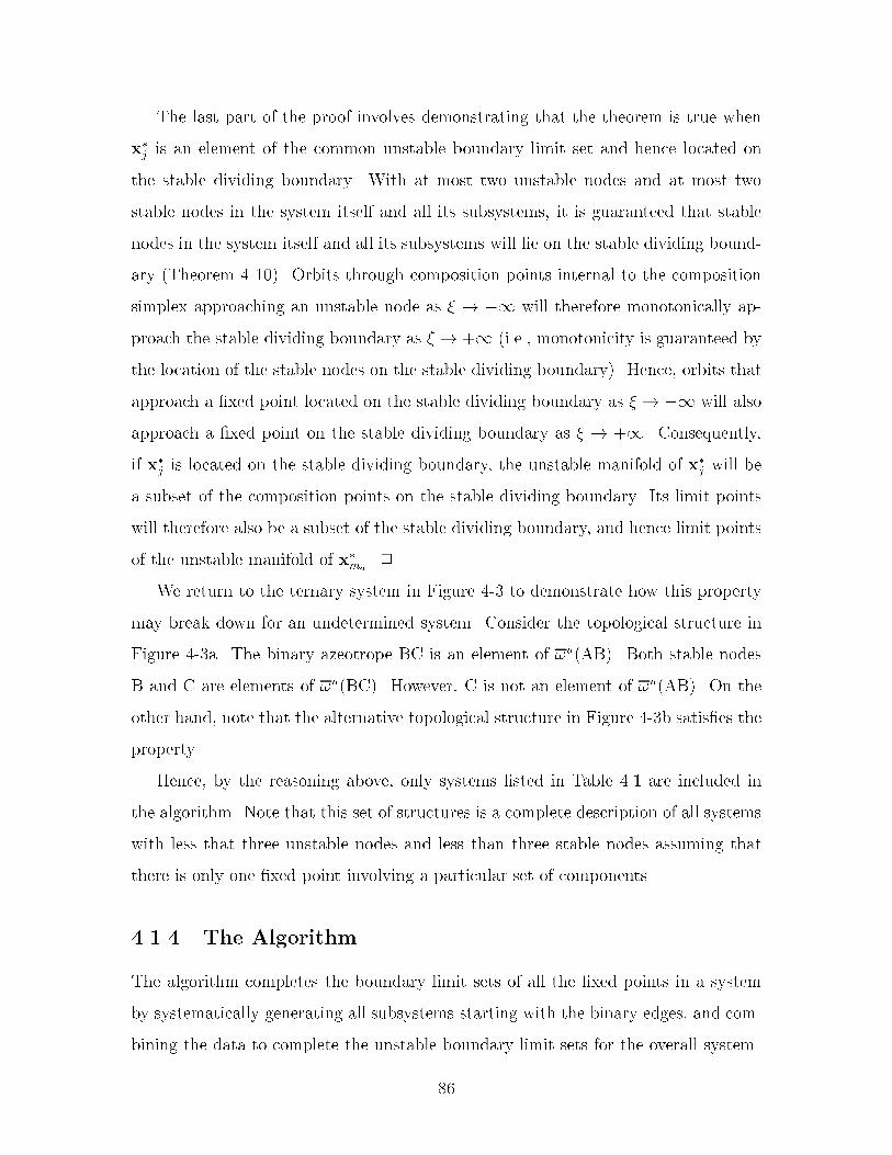
The last part of the proof involves demonstrating that the theorem is true when
x�j is an element of the common unstable boundary limit set and hence located on
the stable dividing boundary� With at most two unstable nodes and at most two
stable nodes in the system itself and all its subsystems� it is guaranteed that stable
nodes in the system itself and all its subsystems will lie on the stable dividing bound
ary �Theorem ����� Orbits through composition points internal to the composition
simplex approaching an unstable node as � � �� will therefore monotonically ap
proach the stable dividing boundary as � � �� �i�e�� monotonicity is guaranteed by
the location of the stable nodes on the stable dividing boundary�� Hence� orbits that
approach a �xed point located on the stable dividing boundary as � � �� will also
approach a �xed point on the stable dividing boundary as � � ��� Consequently�
if x�j is located on the stable dividing boundary� the unstable manifold of x�j will be
a subset of the composition points on the stable dividing boundary� Its limit points
will therefore also be a subset of the stable dividing boundary� and hence limit points
of the unstable manifold of x�ma� �
We return to the ternary system in Figure �� to demonstrate how this property
may break down for an undetermined system� Consider the topological structure in
Figure ��a� The binary azeotrope BC is an element of �u�AB�� Both stable nodes
B and C are elements of �u�BC�� However� C is not an element of �u�AB�� On the
other hand� note that the alternative topological structure in Figure ��b satis�es the
property�
Hence� by the reasoning above� only systems listed in Table ��� are included in
the algorithm� Note that this set of structures is a complete description of all systems
with less that three unstable nodes and less than three stable nodes assuming that
there is only one �xed point involving a particular set of components�
����� The Algorithm
The algorithm completes the boundary limit sets of all the �xed points in a system
by systematically generating all subsystems starting with the binary edges� and com
bining the data to complete the unstable boundary limit sets for the overall system�
�

Table ���� Topological structures included in the algorithm�
System Unstable nodes Stable nodes ncazeotrope� � � none� � � unstable node� � � stable node� � � none� � � unstable node� � � stable node� � � none � � unstable node� � � stable node�� � � none�� � � saddle
The number of subsystems involving i components in a system with nc components
is given by�nci
�� nc�
i��nc�i �� Hence� the number of subsystems necessary to analyze is
therefore Nnc �Pnc
i�nc�
i��nc�i �� For i � �� we get
Pnci�
nc�i��nc�i �
� �nc �Cormen et al��
������ Therefore� Nnc � �nc���nc� Assuming that analyzing a particular subsystem
requires a �xed amount of time� the worstcase running time when analyzing a system
of nc components is therefore of O��nc�� i�e�� exponential� However� as it is expected
that nc typically will be in the order of ���� the running time should not impose a
great limitation on the applicability of the algorithm�
By De�nition ��� the elements in the unstable boundary limit set of a �xed point
are limit points to the �xed point s unstable manifold� If the �xed point itself and the
other composition points in its unstable manifold are located on one of the faces of
the overall composition simplex� i�e�� only involve a subset of the components in the
overall system� the elements in the unstable boundary limit set will also be located
in the same subsystem� This implies that when the unstable boundary limit sets for
this particular subsystem are complete� the unstable boundary limit set for the �xed
point with respect to the overall system is complete� When completing the unstable
boundary limit set of a system involving k components we therefore only need to
focus on the �xed points that have composition points involving all k components in
their unstable manifolds� These are�
�
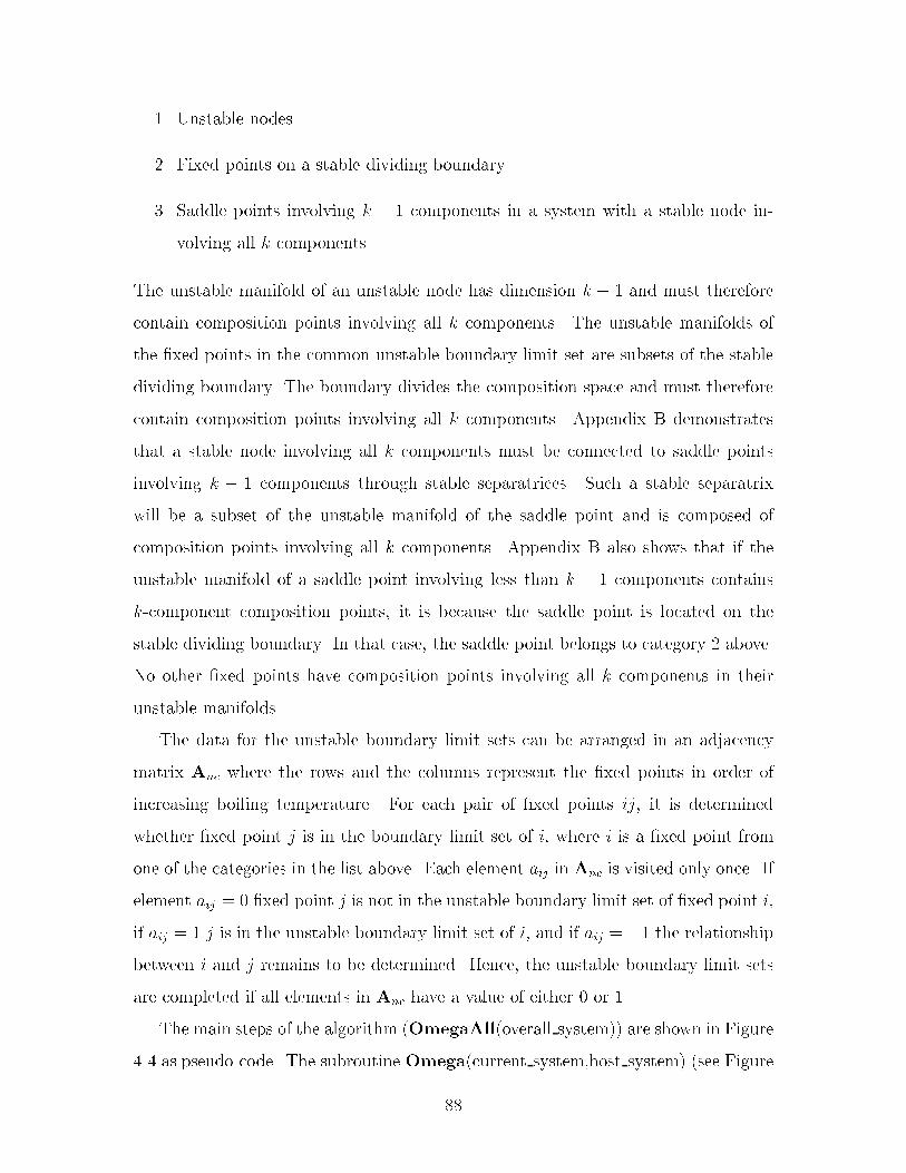
�� Unstable nodes
�� Fixed points on a stable dividing boundary
�� Saddle points involving k � � components in a system with a stable node in
volving all k components
The unstable manifold of an unstable node has dimension k � � and must therefore
contain composition points involving all k components� The unstable manifolds of
the �xed points in the common unstable boundary limit set are subsets of the stable
dividing boundary� The boundary divides the composition space and must therefore
contain composition points involving all k components� Appendix B demonstrates
that a stable node involving all k components must be connected to saddle points
involving k � � components through stable separatrices� Such a stable separatrix
will be a subset of the unstable manifold of the saddle point and is composed of
composition points involving all k components� Appendix B also shows that if the
unstable manifold of a saddle point involving less than k � � components contains
kcomponent composition points� it is because the saddle point is located on the
stable dividing boundary� In that case� the saddle point belongs to category � above�
No other �xed points have composition points involving all k components in their
unstable manifolds�
The data for the unstable boundary limit sets can be arranged in an adjacency
matrix Anc where the rows and the columns represent the �xed points in order of
increasing boiling temperature� For each pair of �xed points ij� it is determined
whether �xed point j is in the boundary limit set of i� where i is a �xed point from
one of the categories in the list above� Each element aij in Anc is visited only once� If
element aij � � �xed point j is not in the unstable boundary limit set of �xed point i�
if aij � � j is in the unstable boundary limit set of i� and if aij � �� the relationship
between i and j remains to be determined� Hence� the unstable boundary limit sets
are completed if all elements in Anc have a value of either � or ��
The main steps of the algorithm �OmegaAll�overall system�� are shown in Figure
�� as pseudocode� The subroutine Omega�current system�host system� �see Figure

��� is called recursively until the unstable boundary limit sets for current system is
complete� The input to OmegaAll�overall system� consists of the set of pure compo
nents� and the set of �xed points in overall system with compositions� temperatures�
and their stability� The input to Omega�current system�host system� consists of the
set of pure components� and the set of �xed points in current system with composi
tions� temperatures� and their stability� and the same for host system� The individual
steps are described in detail below� Note that the procedures for systems ��� only
dier in the �rst step�
OmegaAll(overall_system)
Initialize Anc (step 1)
Complete binary edges (step 2) If (number of components in overall_system) ≥ 3 Set current_system = overall_system Omega(current_system,overall_system) EndIf Complete Anc (step 14)
Figure ��� The overall algorithm for completing the unstable boundary limit sets�
Step �� initialize Anc� set aij � � if j is an unstable node� i is a stable node� or
if TiB � Tj
B� Set all other elements equal to ��
Step �� complete binary edges� if two pure components i and j form a minimum
boiling binary azeotrope k� then aki � akj � �� If they form a maximum boiling
azeotrope� then aik � ajk � �� Otherwise� aij � � if TiB � Tj
B� or aji � � if TiB � Tj
B�
Step �� construct all subsystems� let current system involve k components�
Then generate k sets of k � � components by removing one component at the time
from the set of pure components in current system� Generate the set of �xed points
for each subsystem by extracting the respective �xed points from the set of �xed
�

Omega(current_system,host_system) If current_system not already explored Then If (number of components in current_system) ≥ 4 Then
For Each sub_system current_system Do (step 3) Omega(sub_system,current_system) EndFor EndIf Switch(current_system) Case = systems 1, 2, 4, and 5 Complete unstable boundary limit set of unstable node (step 4) Case = systems 3 and 6 Complete unstable boundary limit set of unstable node (step 4) Establish connections with stable node (step 5) Case = systems 7 and 10 Complete unstable boundary limit sets of unstable nodes (step 6)
Construct common unstable boundary limit set ( uc) (step 7)
Evaluate stability of fixed points in uc (step 8)
Complete unstable boundary limit sets of fixed points in uc (step 9) Case = system 8 Complete unstable boundary limit sets of unstable nodes (step 10)
Construct common unstable boundary limit set ( uc) (step 7)
Evaluate stability of fixed points in uc (step 8)
Complete unstable boundary limit sets of fixed points in uc (step 9)
Case = system 9 Complete unstable boundary limit sets of unstable nodes (step 11)
Construct common unstable boundary limit set ( uc) (step 7)
Evaluate stability of fixed points in uc (step 8)
Complete unstable boundary limit sets of fixed points in uc (step 9)
Case = system 11 Complete unstable boundary limit sets of unstable nodes (step 12)
Construct common unstable boundary limit set ( uc) (step 7)
Evaluate stability of fixed points in uc (step 8)
Complete unstable boundary limit sets of fixed points in uc (step 9)
EndSwitch EndIf If hostsystem ≠ current_system Then Update adjacency matrix of host_system (step 13) EndIf
Figure ��� The subroutine Omega�current system��
��

points in current system� Then determine the stability of each �xed point in every
subsystem� Fixed points that are unstable or stable nodes in current system will also
be unstable or stable nodes in all subsystems where they are present� Therefore only
the stability of saddle points need to be reevaluated when subsystems are analyzed�
This can be achieved by performing a new linear stability analysis around each of the
saddle points in the subsystems�
Step �� complete unstable boundary limit set of unstable node� the unsta
ble boundary limit sets of all subsystems are complete� In current system the unstable
node is the only �xed point with composition points involving all components in its
unstable manifold� The unstable boundary limit set of the unstable node is completed
by applying Theorem ��� The procedure goes as follows� let i denote the unstable
node� Then if aij � ��� set aij � ��
Step �a �system ��� establish connections to stable node� the reasoning
behind this procedure is presented in Appendix B� Let x�q be the stable node involving
all components in current system� and let current system involve k components� Then
x�q should be added to the unstable boundary limit sets of all saddle points involving
k � � components�
Step �b �system ��� establish connections to stable node� the reasoning
behind this procedure is presented in Appendix B� Let x�q be the stable node involving
all components in current system� and let current system involve k components� Then
x�q should be added to the unstable boundary limit sets of all k�� component saddle
points� except the k � � component saddle points that already have the other stable
node in their unstable boundary limit set�
Step �� complete unstable boundary limit sets of unstable nodes� the
unstable boundary limit sets of all subsystems are complete� Current system has two
unstable nodes and hence a stable dividing boundary� The unstable boundary limit
set of each unstable node must be completed before the common unstable boundary
��
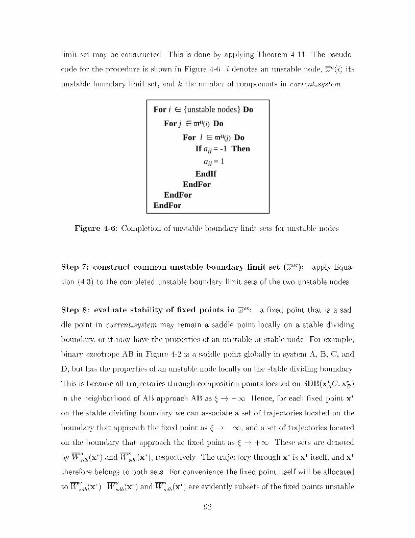
limit set may be constructed� This is done by applying Theorem ���� The pseudo
code for the procedure is shown in Figure ��� i denotes an unstable node� �u�i� its
unstable boundary limit set� and k the number of components in current system�
For i {unstable nodes} Do
For j u(i) Do
For l u(j) Do If ail = -1 Then
ail = 1
EndIf EndFor EndFor EndFor
Figure ��� Completion of unstable boundary limit sets for unstable nodes�
Step �� construct common unstable boundary limit set ��uc�� apply Equa
tion ����� to the completed unstable boundary limit sets of the two unstable nodes�
Step � evaluate stability of xed points in �uc� a �xed point that is a sad
dle point in current system may remain a saddle point locally on a stable dividing
boundary� or it may have the properties of an unstable or stable node� For example�
binary azeotrope AB in Figure �� is a saddle point globally in system A� B� C� and
D� but has the properties of an unstable node locally on the stable dividing boundary�
This is because all trajectories through composition points located on SDB�x�AC�x�B�
in the neighborhood of AB approach AB as � � ��� Hence� for each �xed point x�
on the stable dividing boundary we can associate a set of trajectories located on the
boundary that approach the �xed point as � � ��� and a set of trajectories located
on the boundary that approach the �xed point as � � ��� These sets are denoted
by Wu
sdb�x�� and W
s
sdb�x��� respectively� The trajectory through x� is x� itself� and x�
therefore belongs to both sets� For convenience the �xed point itself will be allocated
to Wu
sdb�x��� W
u
sdb�x�� and W
s
sdb�x�� are evidently subsets of the �xed points unstable
��

and stable manifolds� In fact� the subscript sdb in Wu
sdb�x�� indicates the subset of
Wu�x�� that is also a subset of the stable dividing boundary� If W
s
sdb�x�� � � then
x� is unstable locally on the stable dividing boundary� Similarly� if Wu
sdb�x�� � fx�g�
x� is stable locally on the stable dividing boundary� Otherwise� x� is a saddle point�
The stability of a �xed point in current system is determined by the number of
positive and negative eigenvalues computed from a linear stability analysis in the
neighborhood of the �xed point� In a system with k components each �xed point
is characterized by k � � eigenvalues� Similarly� the stability of a �xed point on the
stable dividing boundary may be determined by the number of positive and negative
eigenvalues computed from a linear stability analysis in the neighborhood of the �xed
point on the stable dividing boundary� These eigenvalues are a subset of the set of
k � � eigenvalues characterizing the stability of the �xed point in current system�
From Theorem ��� it follows that if a �xed point �x�� is an element of the common
unstable boundary limit set its unstable manifold �Wu�x��� will be a subset of the
stable dividing boundary provided that current system and all its subsystems have
at most two unstable and at most two stable nodes� Hence� Wu
sdb�x�� � W
u�x���
Consequently� the number of positive eigenvalues characterizing the stability of the
�xed point on the stable dividing boundary must be the same as for current system�
Because the stable dividing boundary has dimension k� � the stability of each �xed
point on the stable dividing boundary is characterized by k�� eigenvalues� Hence� the
local stability of �xed point x� on the stable dividing boundary can be found simply
by computing the number of positive �#�sdb�x
��� and negative eigenvalues �#�sdb�x
���
applying Equations ����� and ������� #��x�� and #��x�� represent the number of
positive and negative eigenvalues in current system� A similar approach is suggested
by Safrit and Westerberg �������
#�sdb�x
�� � #��x�� �x� � �uc�x�ma�x�mb
� �����
#�sdb�x
�� � #��x��� � �x� � �uc�x�ma�x�mb
� ������
��

Step �� complete unstable boundary limit sets of xed points in �uc� a sta
ble dividing boundary in a k component system has dimension k��� The topological
structure may be characterized according to Table ��� by the number of unstable and
stable nodes� and whether there is an azeotrope involving all components located on
the boundary� Completion of the unstable boundary limit sets is accomplished using
the corresponding procedure in Figure ���
Step ��� complete unstable boundary limit set of unstable nodes� the
reasoning behind this procedure is presented in Appendix B� The unstable boundary
limit sets of all subsystems are complete� Complete the unstable boundary limit
set of the unstable node located on the facet the procedure described in Figure �
�� Let x�m be the unstable node involving all components in current system� and let
current system involve k components� Add all the nc � � component saddle points
to the unstable boundary limit set of x�m� except the nc� � component saddle points
that are already elements in the unstable boundary limit set of the unstable node
located on the facet� Complete the unstable boundary limit set of x�m by applying
the procedure described in Figure ���
Step ��� complete unstable boundary limit set of unstable nodes� the
reasoning behind this procedure is presented in Appendix B� The unstable boundary
limit sets of all subsystems are complete� Include the stable node in the unstable
boundary limit set of both unstable nodes� The unstable boundary limit sets of the
unstable nodes are completed by applying the procedure described in Figure ���
Step ��� complete unstable boundary limit set of unstable nodes� include
the saddle point in the unstable boundary limit sets of both unstable nodes� The
unstable boundary limit sets of the unstable nodes are completed by applying the
procedure described in Figure ���
Step ��� update adjacency matrix� whenever a subsystem is completed the
adjacency matrix of host system should be updated� If component j is an element
��

of the unstable boundary limit set of component i in a subsystem� j is also in the
unstable boundary limit set of i in host system�
Step ��� complete Anc� in a k component subsystem the unstable boundary
limit sets of the �xed points characterized as having composition points involving all
k components in their unstable manifold are completed� i�e�� unstable nodes� �xed
points on a stable dividing boundary� and saddle points connected to stable node
located internal to the subsystem� No other �xed points will have elements added to
their unstable boundary limit set in that particular subsystem� When all subsystems
are explored� the overall system is explored based on the same strategy� Hence� when
the unstable boundary limit sets of the overall system are completed no new elements
may be added to any unstable boundary limit set� Therefore the remaining elements
are set to zero� i�e�� if aij � ��� set aij to zero�
��� Enumerate Product Sequences
In Chapter � it is demonstrated that at the limiting conditions of very high re�ux
ratio� large number of trays� and linear pot composition boundaries an nc compo
nent mixture located internal to a batch distillation region will produce exactly nc
product cuts� The product cuts will have compositions equal to �xed points� and no
other product compositions may be produced� In addition� the following relationship
between the �xed points in a product sequence must be true� if pk represents product
cut k� then pk� � �u�pl� �l � �� � � � � k �Corollary ���� To summarize� the properties
of a feasible product sequence are�
Property � A sequence consists of nc �xed points�
Property � Each subsequent product cut has to be an element of the unstable
boundary limit sets of all the preceding product cuts�
These properties lead to the following algorithm for enumerating the feasible prod
uct sequences in the composition simplex of an nc component system� The unstable
boundary limit sets of the system may be represented as a directed graph with�
��
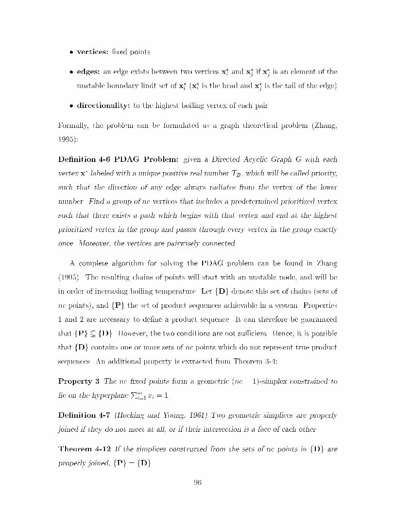
� vertices� �xed points
� edges� an edge exists between two vertices x�i and x�j if x�j is an element of the
unstable boundary limit set of x�i �x�i is the head and x�j is the tail of the edge�
� directionality� to the highest boiling vertex of each pair
Formally� the problem can be formulated as a graph theoretical problem �Zhang�
������
De nition �� PDAG Problem� given a Directed Acyclic Graph G with each
vertex x� labeled with a unique positive real number TB� which will be called priority�
such that the direction of any edge always radiates from the vertex of the lower
number� Find a group of nc vertices that includes a predetermined prioritized vertex
such that there exists a path which begins with that vertex and end at the highest
prioritized vertex in the group and passes through every vertex in the group exactly
once� Moreover� the vertices are pairwisely connected�
A complete algorithm for solving the PDAG problem can be found in Zhang
������� The resulting chains of points will start with an unstable node� and will be
in order of increasing boiling temperature� Let fDg denote this set of chains �sets of
nc points�� and fPg the set of product sequences achievable in a system� Properties
� and � are necessary to de�ne a product sequence� It can therefore be guaranteed
that fPg � fDg� However� the two conditions are not su�cient� Hence� it is possible
that fDg contains one or more sets of nc points which do not represent true product
sequences� An additional property is extracted from Theorem ���
Property � The nc �xed points form a geometric �nc � ���simplex constrained to
lie on the hyperplanePnc
i� xi � ��
De nition �� �Hocking and Young� �� Two geometric simplices are properly
joined if they do not meet at all� or if their intersection is a face of each other�
Theorem ��� If the simplices constructed from the sets of nc points in fDg are
properly joined� fPg � fDg�
��
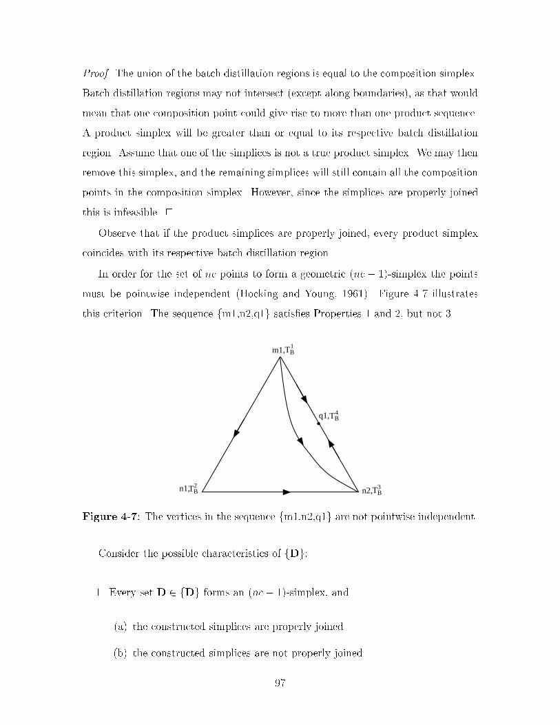
Proof� The union of the batch distillation regions is equal to the composition simplex�
Batch distillation regions may not intersect �except along boundaries�� as that would
mean that one composition point could give rise to more than one product sequence�
A product simplex will be greater than or equal to its respective batch distillation
region� Assume that one of the simplices is not a true product simplex� We may then
remove this simplex� and the remaining simplices will still contain all the composition
points in the composition simplex� However� since the simplices are properly joined
this is infeasible� �
Observe that if the product simplices are properly joined� every product simplex
coincides with its respective batch distillation region�
In order for the set of nc points to form a geometric �nc� ��simplex the points
must be pointwise independent �Hocking and Young� ������ Figure �� illustrates
this criterion� The sequence fm��n��q�g satis�es Properties � and �� but not ��
TB3n2,TB
2n1,
•TB
4q1,
TB1m1,
Figure ��� The vertices in the sequence fm��n��q�g are not pointwise independent�
Consider the possible characteristics of fDg�
�� Every set D � fDg forms an �nc� ��simplex� and
�a� the constructed simplices are properly joined�
�b� the constructed simplices are not properly joined�
��

�� One or more of the sets D � fDg does not form an �nc � ��simplex �the
respective nc points are not pointwise independent�� and
�a� the simplices constructed from the remaining sets are properly joined�
�b� the simplices constructed from the remaining sets are not properly joined�
Assuming that every set D � fDg forms an �nc � ��simplex the following pro
cedure may be applied to check if the simplices are properly joined� form �nc � ��
simplices from each set D � fDg� If at least one �xed point can be found that is
located internal to or on a facet of a simplex� and this �xed point is not in the set
of �xed points de�ning the simplex� the set of simplices will not be properly joined�
since every �xed point is a face ��simplex� of one or more simplices� Conversely� if no
�xed point is located internal to or on a facet of a product simplex� the set of product
simplices are properly joined� A geometric �k � ��simplex is de�ned by Equation
������� where k � nc �Hocking and Young� ������
� � fh � Rnc � h �k��Xi�
fidi� fi � � �i � �� � � � � k � � andk��Xi�
fi � �g ������
where di �i � �� � � � � k � � represent the vertices of the ksimplex� and fi �i �
�� � � � � k � � represent barycentric coordinates� An �nc � ��simplex � in a system
with nc components is de�ned by nc vertices� Hence k � nc� The vertices are the
�xed points in the set D� Let h represent a �xed point which is not in D� and E
the set of �xed points in the system� For every h � E and every D � fDg apply
Equation ������ to h and D� If no combination of h and D satis�es Equation �����
fDg represents the set of true product sequences �category �a��
If no barycentric coordinate is negative� and more than one but less than nc
barycentric coordinates are greater than zero this implies that h is located on a facet
of the simplex "� �de�ned by "D�� If nc barycentric coordinates are greater than zero
h is located internal to "�� In either case the simplices generated from fDg are not
properly joined �category �b��
�

This procedure may be applied directly if fDg belongs to category � above� How
ever� if fDg belongs to category � the procedure must be applied with a slight modi
�cation� remove the set�s� fDnpig that do not satisfy Property �� The remaining sets
are denoted by fDpig� Let h represent a �xed point which is neither in Dpi nor in
fDnpig� For every h � E and every D � fDpig apply Equation ������ to h and D� If
no combination of h and D satis�es Equation ����� fDpig represents the set of true
product sequences �category �a��
Finally� we need to deal with categories �b and �b� Consider the ternary system
Figure � � Three sequences satisfy Properties �� �� and �� P� � fL�I�IHg� P� � fL�I
H�LIHg� and P� � fL�H�LIHg� The �simplices formed from these three sequences
are not properly joined� since the simplex formed from P� and P� intersect� In fact�
batch distillation region B� �bounded by the straight lines connecting L� I� IH� and
LIH� is an exception where the simplex bounded by the product compositions does
not coincide with the batch distillation region itself� However� P�� P�� and P� are all
true product sequences�
TBHH,TB
II,
TBLL,
TBI-H
•
•
TBL-I-H
1
2
3
TBHH,TB
II,
TBLL,
TBI-H
•
•
TBL-I-H
a) b)
Figure �� Intersecting product simplices� The order of boiling temperatures�TL�mB � TI�n
B � TH�nB � TL�I�n
B � TL�I�H�qB �
On the other hand� consider the ternary system in Figure ��� In Figure �� there
are �ve batch distillation regions� and hence �ve feasible product sequences repre
sented by P� �fm��n��n�g� P� � fm��n��q�g� P� � fm��n��q�g� P� � fm��n��q�g�
and P� � fm��n��q�g� In Figure ��b the position of the stable node q� has changed�
��

However� note that the topological structure of the system� and hence the unstable
boundary limit sets have not changed� The sequence of points fm��n��q�g satis�es all
three properties above� Nevertheless� fm��n��q�g does not correspond to a product
sequence� Looking closely at this map� it is found that no composition point would
give rise to sequence fm��n��q�g� but rather one of the other sequences� Consequently�
this map only has four batch distillation regions�
TB1m1,
• TB2m2,
TB6q1, •
•
1
2
3
4
5TB
3n1,
TB4n2,
TBn3, 5
b)
TB1m1,
• TB2m2,
TBq1, 6•
•
1
2
3
4
5
TB3n1,
TB4n2,
TB5n3,
a)
Figure ��� a� Five batch distillation regions� b� Four batch distillation regions�
An additional property may therefore be formulated�
Property � For a �nc � ���simplex to be a product simplex one or more compo�
sition points must give rise to the corresponding sequence of nc �xed points when
batch distillation is applied� These composition points will form the respective batch
distillation region and lie internal to the simplex�
In fact� observe that Property � supplies both necessary and su�cient conditions to
characterize a product simplex� following De�nition ��� the composition points that
give rise to the same product sequence form a batch distillation region� The product
simplex formed by the nc product cuts coincides or is greater than the respective
batch distillation region� Hence� in order for an �nc � ��simplex to be a product
simplex� it must contain the respective batch distillation region�
However� Properties �� �� and � are easier to use� and when the product simplices
are properly joined� these three properties are both necessary and su�cient to char
���

acterize a product sequence and to enumerate all the true product sequences� When
the simplices are not properly joined Properties �� �� and � only supply necessary
conditions to characterize a product sequence� From the many systems we have stud
ied we believe that the following procedure is su�cient to eliminate the simplices
that satisfy Properties �� �� and �� but not Property �� although a proof is currently
lacking�
Let f�pig represent the set of simplices satisfying Properties �� �� and �� Further
more� let f�npjpi g � f�pig represent the set of simplices for which h results in positive
barycentric coordinates� The simplices containing h will intersect f�npjpi g� Let f�h
pig
represent this set of simplices� We are left with determining if one or more of the
simplices in f�hpig does not satisfy Property �� and hence is not a product simplex�
but rather of the type illustrated by Figure ��b� Such a simplex is characterized
as being a subset of f�npjpi g� a simplex in f�h
pig which shares all its vertices except
h with f�npjpi g is a subset of f�npj
pi g� In addition� there must be at least two other
simplices in f�hpjg� Remove simplices satisfying these characteristics from f�pig�
Enumeration of all product simplices in the system is complete�
��� Example� Ternary System
The following example serves to demonstrate the procedure for enumerating the prod
uct sequences when the system belongs to category �b in the previous section� The
compositions of the �xed points in the ternary system are listed in Table ���� and
the unstable boundary limit sets are listed in Table ���� For clarity� the composition
simplex is shown in Figure ���� Observe that the ternary system exhibits a similar
topological structure to the one shown in Figure ���
Solving the PDAG problem results in the set fDg� D� � fA� C� BCg� D� �
fA� AB� ABCg� D� � fA� BC� ABCg� D� � fB� BC� ABCg� andD� � fB� AB� ABCg�
It is found that the respective three points in each of the sets above form a
�simplex� Therefore� f�pig � f��������������g� where �i is the �simplex
formed from the �xed points in Di� Next� we need to determine whether the �
���

Table ���� Fixed points in ternary system�
e A B CA � � �B � � �C � � �
AB ��� ��� �BC � ��� ���
ABC ��� ��� ���
Table ���� Unstable boundary limit sets�
e �u�x�e�A C� AB� BC� ABCB AB� BC� ABCC BCAB ABCBC ABCABC
simplices in f�pig are properly joined� Let fhig represent the set of �xed points
that are not in the set Di� Then fh�g � fB� AB� ABCg� fh�g � fB� BC� Cg�
fh�g � fB� AB� Cg� fh�g � fA� AB� Cg� and fh�g � fA� BC� Cg� Table ��� shows
the barycentric coordinates computed when Equation ���� is applied to Di and every
hi � fhig�
Table ��� shows that the ternary azeotrope ABC is located inside ��� Hence�
the simplices are not properly joined� and f�npjpi g � f��g� Furthermore� f�ABC
pi g �
f�����������g� We �nd that �� is a subset of ��� because D� � D� � ABC�
In addition� there are three more simplices in f�ABCpi g� Consequently� simplex ��
should be removed from f�pig� The true product sequences are D�� D�� D�� and D��
���

•
•
TBBC, 5
TB6
ABC
TB4AB,
TB1A,
TB2B,TB
3C,
Figure ���� Composition simplex with batch distillation regions for the ternarysystem�
Table ���� Barycentric coordinates�
D� D� D�
h� fA fC fBC h� fA fAB fABC h� fA fBC fABCB � ����� ���� B �� � � B �� ���� ����
AB �� ����� ��� BC ���� �� �� AB ���� ���� ��� �
ABC ��� ���� ���� C ���� ��� � C ���� ��� � ����
D� D�
h� fB fBC fABC h� fB fAB fABCA ��� ����� ���� A �� � �
AB ���� ���� ���� BC ��� ���� ��
C ��� �� � C ��� ���� �
��� Example� Five�Component System
The algorithm for constructing the composition simplex in Figure �� was employed
to the system acetone �A�� chloroform �C�� methanol �M�� ethanol �E�� and benzene
�B� at � atmosphere� The �xed points in this system are taken from Fidkowski et al�
������ and are shown in Table ����
The unstable boundary limit set matrix is initialized by applying the procedure
in Section ������ The binary edges are then completed� The resulting matrix is given
in Table ���� The rows and columns represent the �xed points ordered according to
���
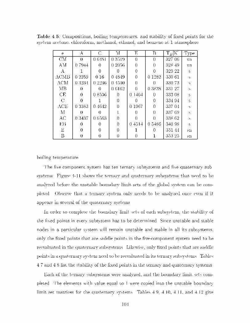
Table ���� Compositions� boiling temperatures� and stability of �xed points for thesystem acetone� chloroform� methanol� ethanol� and benzene at � atmosphere�
e A C M E B TB�K� TypeCM � ���� � ������ � � ������ unAM ������ � ������ � � �� ��� unA � � � � � ������ s
ACMB ������ ���� ��� �� � ���� � ������ sACM ������ ������ ������ � � ������ sMB � � ������ � ��� � ������ sCE � �� ��� � ������ � ����� sC � � � � � ������ s
ACE ���� � ������ � ������ � ������ sM � � � � � ������ sAC ������ ������ � � � �� ��� sEB � � � ������ ���� � ����� sE � � � � � ������ snB � � � � � ������ sn
boiling temperature�
The �vecomponent system has ten ternary subsystems and �ve quaternary sub
systems� Figure ��� shows the ternary and quaternary subsystems that need to be
analyzed before the unstable boundary limit sets of the global system can be com
pleted� Observe that a ternary system only needs to be analyzed once even if it
appears in several of the quaternary systems�
In order to complete the boundary limit sets of each subsystem� the stability of
the �xed points in every subsystem has to be determined� Since unstable and stable
nodes in a particular system will remain unstable and stable in all its subsystems�
only the �xed points that are saddle points in the �vecomponent system need to be
reevaluated in the quaternary subsystems� Likewise� only �xed points that are saddle
points in a quaternary system need to be reevaluated in its ternary subsystems� Tables
��� and �� list the stability of the �xed points in the ternary and quaternary systems�
Each of the ternary subsystems were analyzed� and the boundary limit sets com
pleted� The elements with value equal to � were copied into the unstable boundary
limit set matrices for the quaternary systems� Tables ���� ����� ����� and ���� give
���

Table ���� The initialized unstable boundary limit matrix for the �vecomponentsystem with completed binary edges�
CM AM A ACMB ACM MB CE C ACE M AC EB E B
CM � �� �� �� �� �� �� � �� � �� �� �� ��AM � � � �� �� �� �� �� �� � �� �� �� ��A � � � �� �� �� �� �� �� �� � �� � �
ACMB � � � � �� �� �� �� �� �� �� �� �� ��ACM � � � � � �� �� �� �� �� �� �� �� ��MB � � � � � � �� �� �� � �� �� �� �CE � � � � � � � � �� �� �� �� � ��C � � � � � � � � �� �� � �� �� �
ACE � � � � � � � � � �� �� �� �� ��M � � � � � � � � � � �� �� � ��AC � � � � � � � � � � � �� �� ��EB � � � � � � � � � � � � � �E � � � � � � � � � � � � � �B � � � � � � � � � � � � � �
the completed unstable boundary limit set matrices for the quaternary subsystems
I��� I��� I��� and I��� Table ���� gives the incomplete unstable boundary limit set matrix
for system I��� The completion of the matrix for I�� will be discussed in more detail
below�
There are two unstable nodes in I��� CM and AM� The unstable boundary limit
sets of CM and AM were completed by applying the procedure in Figure ��� Since
CE is an element of �u�CM� and ACE is an element of �u�CE�� ACE must also be an
element of �u�CM�� ACE was therefore added to �u�CM�� Also� since A is an element
of �u�AM� and ACE is an element of �u�A�� ACE must be an element of �u�AM��
ACE was therefore added to �u�AM�� Next� the common unstable boundary limit set
was determined �see Equation �������� The subscript in �uc���CM�AM� indicates that
this is the common unstable boundary limit set for system I���
�uc���CM�AM� � fACM�CE�C�ACE�M�AC�Eg �
fA�ACM�ACE�M�AC�Eg ������
� fACM�ACE�M�AC�Eg
���
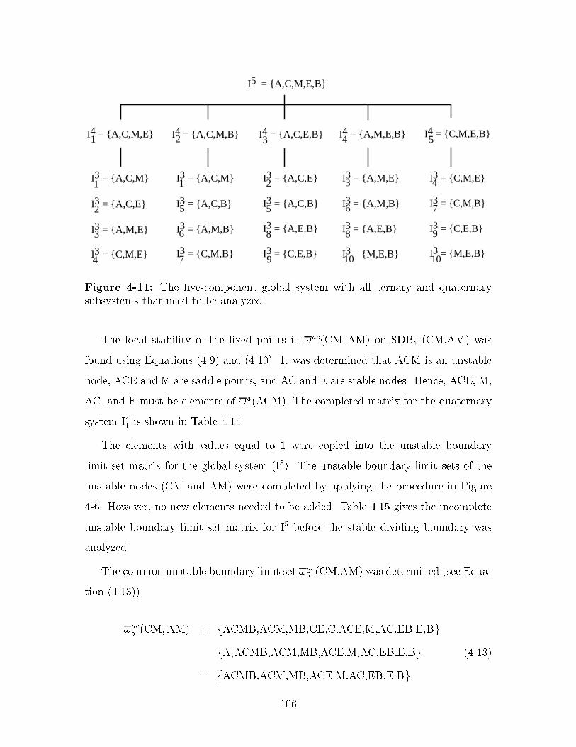
I5 = {A,C,M,E,B}
I4 = {A,C,M,E}1 I4 = {A,C,M,B}2 I4 = {A,C,E,B}3I4 = {A,M,E,B}4 I4 = {C,M,E,B}5
I3 = {A,C,M}1
I3 = {A,C,E}2
I3 = {A,M,E}3
I3 = {C,M,E}4
I3 = {A,C,M}1
I3 = {A,C,B}5
I3 = {A,M,B}6
I3 = {C,M,B}7
I3 = {A,C,E}2
I3 = {A,C,B}5
I3 = {A,E,B}8
I3 = {C,E,B}9
I3 = {A,M,B}6
I3 = {A,E,B}8
I3 = {M,E,B}10
I3 = {A,M,E}3 I3 = {C,M,E}4
I3 = {C,M,B}7
I3 = {C,E,B}9
I3 = {M,E,B}10
Figure ���� The �vecomponent global system with all ternary and quaternarysubsystems that need to be analyzed�
The local stability of the �xed points in �uc�CM�AM� on SDB���CM�AM� was
found using Equations ����� and ������� It was determined that ACM is an unstable
node� ACE and M are saddle points� and AC and E are stable nodes� Hence� ACE� M�
AC� and E must be elements of �u�ACM�� The completed matrix for the quaternary
system I�� is shown in Table �����
The elements with values equal to � were copied into the unstable boundary
limit set matrix for the global system �I��� The unstable boundary limit sets of the
unstable nodes �CM and AM� were completed by applying the procedure in Figure
��� However� no new elements needed to be added� Table ���� gives the incomplete
unstable boundary limit set matrix for I� before the stable dividing boundary was
analyzed�
The common unstable boundary limit set �uc� �CM�AM� was determined �see Equa
tion ��������
�uc� �CM�AM� � fACMB�ACM�MB�CE�C�ACE�M�AC�EB�E�Bg �
fA�ACMB�ACM�MB�ACE�M�AC�EB�E�Bg ������
� fACMB�ACM�MB�ACE�M�AC�EB�E�Bg
���
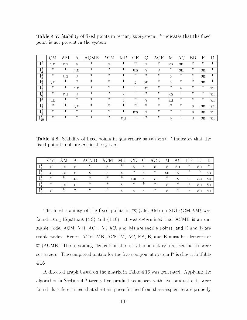
Table ���� Stability of �xed points in ternary subsystems� � indicates that the �xedpoint is not present in the system�
CM AM A ACMB ACM MB CE C ACE M AC EB E BI�� un un s � s � � s � sn sn � � �I�� � � un � � � un s s � sn � sn �I�� � un s � � � � � � s � � sn �I�� un � � � � � s sn � s � � sn �I�� � � un � � � � un � � s � � snI�� � un s � � s � � � sn � � � snI�� un � � � � s � s � sn � � � snI�� � � un � � � � � � � � s sn snI�� � � � � � � un s � � � s sn snI��� � � � � � un � � � s � s sn sn
Table ��� Stability of �xed points in quaternary subsystems� � indicates that the�xed point is not present in the system�
CM AM A ACMB ACM MB CE C ACE M AC EB E BI�� un un s � s � s s s s sn � sn �I�� un un s s s s � s � sn s � � snI�� � � un � � � un s s � s s sn snI�� � un s � � s � � � s � s sn snI�� un � � � � s s s � s � s sn sn
The local stability of the �xed points in �uc� �CM�AM� on SDB��CM�AM� was
found using Equations ����� and ������� It was determined that ACMB is an un
stable node� ACM� MB� ACE� M� AC� and EB are saddle points� and E and B are
stable nodes� Hence� ACM� MB� ACE� M� AC� EB� E� and B must be elements of
�u�ACMB�� The remaining elements in the unstable boundary limit set matrix were
set to zero� The completed matrix for the �vecomponent system I� is shown in Table
�����
A directed graph based on the matrix in Table ���� was generated� Applying the
algorithm in Section ��� twenty�ve product sequences with �ve product cuts were
found� It is determined that the �simplices formed from these sequences are properly
���

Table ���� The completed boundary limit set matrix for system I���
CM AM A ACMB ACM MB C M AC B
CM � � �� � � � � � � �AM � � � � � � �� � � �A � � � �� �� �� �� �� � �
ACMB � � � � � � �� � � �ACM � � � � � �� �� � � ��MB � � � � � � �� � �� �C � � � � � � � �� � �M � � � � � � � � � �AC � � � � � � � � � �B � � � � � � � � � �
Table ����� The completed boundary limit set matrix for system I���
A CE C ACE AC EB E B
A � � �� � � � � �CE � � � � � � � �C � � � �� � �� �� �
ACE � � � � � � � �AC � � � � � �� �� �EB � � � � � � � �E � � � � � � � �B � � � � � � � �
joined� Hence� they represent the true product sequences� The product sequences are
shown in Figure ��� and are also listed in Table ����� �� sequences start with CM�
and �� sequences will produce AM as the �rst cut�
�� Summary
An algorithm for characterizing the batch distillation composition simplex is de
scribed� Construction of the batch distillation composition simplex is accomplished
through completion of the unstable boundary limit sets� The completed unstable
boundary limit sets accurately represent the topological structure of the composition
simplex� and also makes it possible to extract all product sequences achievable when
��

Table ����� The completed boundary limit set matrix for system I���
AM A MB M EB E B
AM � � � � � � �A � � �� �� � � �MB � � � � � � �M � � � � �� � ��EB � � � � � � �E � � � � � � �B � � � � � � �
Table ����� The completed boundary limit set matrix for system I���
CM MB CE C M EB E B
CM � � � � � � � �MB � � �� �� � � � �CE � � � � �� � � �C � � � � �� �� �� �M � � � � � �� � ��EB � � � � � � � �E � � � � � � � �B � � � � � � � �
applying batch distillation� The derived algorithm is guaranteed to �nd the correct
unstable boundary limit sets for all �xed points in the system provided that the sys
tem itself and all its subsystems have at most two unstable and at most two stable
nodes� and that a stable dividing boundary locally exhibits at most two unstable
and at most two stable nodes� This restriction ensures that the system is globally
determined� i�e�� topological requirements of the composition simplex given by the
compositions� boiling temperatures� and stability of each �xed point can be met by
a unique combination of unstable boundary limit sets� The topological structures in
cluded in the algorithm are divided into eleven systems� and are characterized by the
number of unstable and stable nodes� and whether the system exhibits an azeotrope
involving all components� Other important properties are also demonstrated� In
particular�
���

Table ����� The incomplete boundary limit set matrix for system I���
CM AM A ACM CE C ACE M AC E
CM � � �� � � � �� � � �AM � � � � �� �� �� � � �A � � � �� �� �� � �� � �
ACM � � � � �� �� �� � � ��CE � � � � � � � �� � �C � � � � � � �� �� � ��
ACE � � � � � � �� �� � �M � � � � � � � � �� �AC � � � � � � � � � �E � � � � � � � � � �
Table ����� The completed boundary limit set matrix for system I���
CM AM A ACM CE C ACE M AC E
CM � � �� � � � � � � �AM � � � � �� �� � � � �A � � � �� �� �� � �� � �
ACM � � � � �� �� � � � �CE � � � � � � � �� � �C � � � � � � �� �� � ��
ACE � � � � � � � �� � �M � � � � � � � � �� �AC � � � � � � � � � �E � � � � � � � � � �
� In a system with two unstable nodes the unstable manifolds of the unstable
nodes are separated by a stable dividing boundary� The boundary is character
ized by the common unstable boundary limit set� i�e�� the �xed points located
on the boundary�
� If a system has only one unstable node� the unstable node s unstable boundary
limit set will contain all the other �xed points in the system�
� A saddle point involving all components cannot exist in a system with only one
unstable or stable node�
���

Table ����� The unstable boundary limit set matrix for the global system before thestable dividing boundary is analyzed�
CM AM A ACMB ACM MB CE C ACE M AC EB E B
CM � � � � � � � � � � � � � �AM � � � � � � � � � � � � � �A � � � � � � � � � � � � � �
ACMB � � � � �� �� �� �� �� �� �� �� �� ��ACM � � � � � �� �� �� � � � �� � ��MB � � � � � � �� �� �� � �� � � �CE � � � � � � � � � �� � � � �C � � � � � � � � �� �� � �� �� �
ACE � � � � � � � � � �� � � � �M � � � � � � � � � � �� �� � ��AC � � � � � � � � � � � �� �� �EB � � � � � � � � � � � � � �E � � � � � � � � � � � � � �B � � � � � � � � � � � � � �
� If a system features two unstable nodes� two stable nodes� and a saddle point
involving all the components� the saddle point must be in the unstable boundary
limit sets of both unstable nodes� and in the stable boundary limit sets of both
stable nodes�
� If a system contains three or more unstable nodes� two stable nodes� �or vice
versa�and a saddle point involving all components the system is globally unde
termined�
� If a system and all its subsystems can be characterized as having at most two
unstable nodes and at most two stable nodes the unstable boundary limit sets
of �xed point x�j is a subset of the unstable boundary limit set of unstable node
x�ma� provided that x�j is an element of the unstable boundary limit set of x�ma
�
The algorithm for constructing the composition simplex is applied to the �ve
component system acetone� chloroform� methanol� ethanol� and benzene� The system
exhibits � azeotropes� The unstable boundary limit sets for the �xed points are
completed� Furthermore� �� product sequences are enumerated�
���

Table ����� The completed unstable boundary limit matrix for the �vecomponentsystem�
CM AM A ACMB ACM MB CE C ACE M AC EB E B
CM � � � � � � � � � � � � � �AM � � � � � � � � � � � � � �A � � � � � � � � � � � � � �
ACMB � � � � � � � � � � � � � �ACM � � � � � � � � � � � � � �MB � � � � � � � � � � � � � �CE � � � � � � � � � � � � � �C � � � � � � � � � � � � � �
ACE � � � � � � � � � � � � � �M � � � � � � � � � � � � � �AC � � � � � � � � � � � � � �EB � � � � � � � � � � � � � �E � � � � � � � � � � � � � �B � � � � � � � � � � � � � �
CM AM
CE ACMB A
C ACE ACM MB ACE
AC AC EB ACEM EBM AC EB
B B E B E AC E E E B B E B
Figure ���� �� product sequences with �ve product cuts�
���

Table ����� �� product sequences with �ve product cuts�
b Product sequence b Product sequence� fCM�ACMB�ACM�ACE�ACg �� fAM� ACMB�ACM�ACE�ACg� fCM�ACMB�ACM�ACE�Eg �� fAM�ACMB�ACM�ACE�Eg� fCM�ACMB�ACM�M�Eg �� fAM�ACMB�ACM�M�Eg� fCM�ACMB�MB�M�Eg �� fAM�ACMB�MB�M�Eg� fCM�ACMB�MB�EB�Eg � fAM�ACMB�MB�EB�Eg� fCM�ACMB�MB�EB�Bg �� fAM�ACMB�MB�EB�Bg� fCM�ACMB�ACE�AC�Bg �� fAM�ACMB�ACE�AC�Bg fCM�ACMB�ACE�EB�Eg �� fAM�ACMB�ACE�EB�Eg� fCM�ACMB�ACE�EB�Bg �� fAM�ACMB�ACE�EB�Bg�� fCM�CE�C�AC�Bg �� fAM�A�ACE�AC�Bg�� fCM�CE�ACE�AC�Bg �� fAM�A�ACE�EB�Eg�� fCM�CE�ACE�EB�Eg �� fAM�A�ACE�EB�Bg�� fCM�CE�ACE�EB�Bg
���

���

Chapter �
Solvent Recovery Targeting
In this chapter� we show that the algorithm for characterizing the batch distillation
composition simplex for a system with an arbitrary number of components can be ex
ploited in a sequential design strategy where process streams or mixed wastesolvent
streams are analyzed for maximum feasible solvent recovery using a targeting ap
proach� We will term this procedure solvent recovery targeting� Solvent recovery
targeting yields an understanding of the barriers to solvent recovery created by a
particular design� e�g�� the existence of a particular azeotrope in solvent mixtures�
This information can then be used to modify the design� aiming at enhanced solvent
recovery and recycling�
We present the application of solvent recovery targeting to two case studies� The
�rst case study is a siloxane monomer process� We will demonstrate that signi�cantly
lower emission levels can be achieved by integrating recovery and recycling of solvent
as part of the process �owsheet� Furthermore� we will show that dynamic simulation
models can be exploited to evaluate proposed process alternatives with respect to
eects on the reaction chemistry from recycling intermediates� In particular� models
yield detailed insight when designing integrated operating policies to increase yield
and selectivity while minimizing formation of undesired byproducts� In the second
case study the production of a carbinol is analyzed� Solvent recovery targeting is
used to assess several possible process modi�cations to improve solvent recovery� In
particular� evaluation of alternative solvents is emphasized�
���

�� Approach
For a given base case� solvent recovery targeting will� given the composition of the
mixture�s� to be separated� predict the correct distillation sequence and calculate
the maximum feasible recovery of each product cut in the sequence� It can further
provide information about all other feasible distillation sequences involving the same
set of pure components� This information is used to evaluate the feasibility of en
hancing solvent recovery in the proposed �owsheet� If necessary� the original design
is modi�ed� and the targeting approach is next applied to the new process streams
to evaluate the modi�cations� The general structure of solvent recovery targeting
is outlined in Figure ��� Analyzing the stream for maximum recovery involves two
tasks� �� locating the stream composition in the correct batch distillation region� and
�� calculating the amounts recovered in each product cut� In the subsequent sections
the dierent steps are described�
Composition Simplex
Analyze stream formaximum recovery
Streamcomposition
Modify process
not acceptable
Final design
Base case
waste streams
Figure ��� Solvent recovery targeting�
���
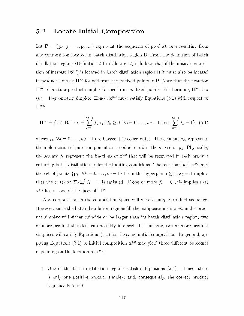
�� Locate Initial Composition
Let P � fp��p�� � � � �pnc��g represent the sequence of product cuts resulting from
any composition located in batch distillation region B� From the de�nition of batch
distillation regions �De�nition �� in Chapter �� it follows that if the initial composi
tion of interest �xp��� is located in batch distillation region B it must also be located
in product simplex �nc formed from the nc �xed points in P� Note that the notation
�nc refers to a product simplex formed from nc �xed points� Furthermore� �nc is a
�nc� ��geometric simplex� Hence� xp�� must satisfy Equations ����� with respect to
�nc�
�nc � fx � Rnc � x �nc��Xk�
fkpk� fk � � �k � �� � � � � nc� � andnc��Xk�
fk � �g �����
where fk �k � �� � � � � nc� � are barycentric coordinates� The element pki represents
the molefraction of pure component i in product cut k in the nc vector pk� Physically�
the scalars fk represent the fractions of xp�� that will be recovered in each product
cut using batch distillation under the limiting conditions� The fact that both xp�� and
the set of points fpk �k � �� � � � � nc � �g lie in the hyperplanePnc
i� xi � � implies
that the criterionPnc��
k� fk � � is satis�ed� If one or more fk � � this implies that
xp�� lies on one of the faces of �nc�
Any composition in the composition space will yield a unique product sequence�
However� since the batch distillation regions �ll the composition simplex� and a prod
uct simplex will either coincide or be larger than its batch distillation region� two
or more product simplices can possibly intersect� In that case� two or more product
simplices will satisfy Equations ����� for the same initial composition� In general� ap
plying Equations ����� to initial composition xp�� may yield three dierent outcomes
depending on the location of xp���
�� One of the batch distillation regions satis�es Equations ������ Hence� there
is only one positive product simplex� and� consequently� the correct product
sequence is found�
���

�� More than one batch distillation region satis�es Equations ������ and the pre
dicted product sequences will produce the same unstable node in the �rst cut�
�� More than one batch distillation region satis�es Equations ������ and the pre
dicted product sequences will give rise to dierent unstable nodes in the �rst
cut�
To illustrate the possible outcomes� consider the ternary system in Figure ��a�
The system has four batch distillation regions and therefore four product sequences�
represented by P� � fm��n��n�g� P� � fm��n��q�g� P� � fm��n��q�g� and P� �
fm��n��q�g� P� and P� have the unstable node m� in common� while P� and P�
have m� in common� Product simplex ��� intersects product simplices ��
�� ���� and
���� The intersections are represented by the domains �a� �a� and �a� respectively�
If xp�� is located in domains �� �b� �b� or �b outcome � above will result� if xp�� is
located in domain �a outcome � above will result� and if xp�� is located in domains
�a or �a outcome � will result� If outcome � or � is encountered further examination
is required in order to determine the correct product sequence�
����� Product Sequences that have an Unstable Node in Com
mon
Consider the ternary system in Figure ��� The system has four batch distillation
regions �see Figure ��b�� Hence four product simplices can be generated� de�ned
by ��� � P� � fm��n��n�g� ��
� � P� � fm��n��q�g� ��� � P� � fm��n��n�g� and
��� � P� � fm��n��n�g as indicated in Figure ��c� They all have the unstable node
m� in common� One of the facets of ��� intersects the stable separatrix connecting
the binary azeotrope n� and the ternary azeotrope at the point t� The composition
simplex can therefore be divided into �ve domains �see Figure ��d�� When applying
Equations ����� �ve possible scenarios can take place depending on the location of
the initial composition� The dierent scenarios are summarized in Table ����
Correct prediction of the true product sequence can be con�rmed by placing xp��
anywhere in the composition space� and then drawing a straight line through xp��
��

b)a)
•
•
•
•
•
•
c)
•
•
•
d)
•
•
1
2
3
4
2a
2b
3a 3b
4a
4b11
4
3
2
TBn3, 5 TB2m2,
TB4n2,
TB1m1,
TB6q1,
TB3n1,
TB3n1,TB
3n1,
TB3n1,
TBn3, 5TBn3, 5
TBn3, 5
TB6q1,TB
6q1,
TB6q1,
TB4n2,TB
4n2,
TB4n2,
TB1m1,TB
1m1,
TB1m1,
TB2m2,TB
2m2,
TB2m2,
•
Figure ��� Ternary system with intersecting product simplices� a� Simple distillation residue curve map� b� Batch distillation regions� c� Product simplices� d�Intersecting domains�
Case Location of Positive True productxp�� product simplex sequence
� B� ��� P�
� B�a ���� �
�� P�
� B�b ���� �
�� P�
� B� ��� P�
B� ��� P�
Table ���� Possible scenarios when testing for positive barycentric coordinates�
and m�� The pot composition path will move along this line away from m� until
it encounters a pot composition boundary �see Chapter ��� In scenario � the pot
composition path intersects the pot composition boundary connecting n� and q� as
���

b)a)
TB2n1,
• TB1m1,
•
•
••
•
t
1
2
34
••
•
t
1
2
34
••
•
t
1
2b
34
2a
d)c)
TBq1, 6
TBn4, 5
TB3n2,TBn3, 3
TB2n1,
TB2n1,TB
2n1,
TB1m1,
TB1m1,TB
1m1,TBq1, 6
TBq1, 6
TBq1, 6
TB3n2,TB
3n2,
TB3n2,
TBn4, 5TBn4, 5
TBn4, 5
TBn3, 3TBn3, 3
TBn3, 3
Figure ��� Ternary system with intersecting product simplices� a� Simple distillation residue curve map� b� Batch distillation regions� c� Product simplices� d�Intersecting domains�
illustrated by Figure ��� The point of intersection is x�a� Further� the line can be
extended until it intersects the pot composition boundary connecting n� and n� at
x�b� The true product sequence is the set of �xed points P resulting from the batch
distillation region that contains the active pot composition boundary� de�ned as the
pot composition boundary that is encountered �rst� Product simplex boundary "�nc��
of product simplex �nc is the facet opposite the unstable node p�� and will be used
to approximate the pot composition boundary� in the same manner product simplices
are used to approximate batch distillation regions� "�nc�� is de�ned by nc� � vectors
formed from the nc� � �xed points that remain when the unstable node is removed
from P� Since it is assumed that the pot composition boundary is linear� i�e�� either
���

located on a facet� or a stable dividing boundary and the �xed points located on
the pot composition boundary lie on a hyperplane� this approximation is an accurate
representation of the actual distance� Obviously� if the number of �xed points located
on the pot composition boundary is equal to nc� �� the pot composition boundary is
linear and equal to the corresponding product simplex boundary� In the case that the
number of �xed points on the pot composition boundary is greater than nc� �� the
approximation may result in an overestimation of the distance� This is because the
product simplex either coincide or is greater than its corresponding batch distillation
region� However� an overestimation of the distance implies that the pot composition
boundary is smaller than its corresponding product simplex boundary� and hence the
batch distillation region is smaller than its corresponding product simplex� Therefore�
it is not the active batch distillation region�
••
•4
1
+
x1a
xp,02
3
x1bTB
3n2,TBn3, 3
TBn4, 5
TBq1, 6TB
1m1,
TB2n1,
Figure ��� The true product sequence is determined by the active pot compositionboundary�
Consider Figure ��� It shows a product simplex for a quaternary mixture pro
jected into R�� The relation to the origin �x � ��� �� �� ��T � is indicated for clarity�
The initial composition is de�ned by�
xp�� � f�p� �nc��Xk�
fkpk � f�p� � ��� f��xp�� �����
where fk �k � f�� � � � � nc� �g are the barycentric coordinates from Equations ������
���

p3
p1
p2
p0
xp,0+
xp,1
origin
Figure ��� Identi�cation of active product simplex boundary�
The intersection with the product simplex boundary �de�ned by p��p�� and p��
at xp�� can be expressed in terms of the relative distance �� the number of times we
need to take the vector �xp�� � p�� in order to get from p� to xp���
xp�� � p� � ��xp�� � p�� �����
Combining Equations ����� and ����� results in a simple relationship between �
and f��
� ��
�� f������
Hence� the relative distance to the product simplex boundary can be measured
in terms of the barycentric coordinate� f�� for the �rst product cut� The larger � is�
the further away from the initial composition is xp��� In order to determine the true
product sequence� it is therefore su�cient to compare the barycentric coordinates f s�
for the positive product simplices� The true product simplex is thus �nc� for which
f �� � MINff s� �s � fpositive product simplicesgg �����
If Equation ����� does not give a unique minimum� i�e�� f s� � f �� �s � fpositive
product simplicesg� then either the product simplex boundaries for the positive prod
���

uct simplices are located on the same facet� or on the stable dividing boundary and
the stable dividing boundary is linear �i�e�� the �xed points in the common unstable
boundary limit set are located on a hyperplane�� In either case� the product simplex
boundaries intersect� in the same manner product simplices may intersect� In order to
determine the true product sequence Equation ����� has to be repeated by replacing
f s� with f s� �
����� Product Sequences that do not have an Unstable Node
in Common
Clearly� this behavior can only be observed in a system with two unstable nodes� and
hence a stable dividing boundary� The correct product sequence is the one for which
the unstable node lies on the same side of the stable dividing boundary as the initial
composition� Consider Figure ��� The stable dividing boundary is composed of the
straight lines between n� and q� and n� and q��
•
•
+
TB2m2,
TBn3, 5
xp,0TB6q1,
x1
x4a•
•
•1 4
TB3n1,
TBn3, 5
TB6q1,
TB4n2,
TB1m1,
xp,0
+
x4b
x4a
x1
2
3
Figure ��� Identi�cation of true product sequence�
Both product simplices � and � will generate positive barycentric coordinates when
applying Equations ����� to the initial composition xp��� although xp�� is truly located
in batch distillation region �� The correct product sequence can be determined by
drawing straight lines through xp�� and each of the unstable nodes� and extending
���

these lines until they intersect the respective pot composition boundaries of batch
distillation regions � and � �x� and x�b�� The line from xp�� to the intersection
represents the path the pot composition orbit would travel during distillation of the
�rst product cut �with composition equal to the unstable node�� Observe that the
line from xp�� to x�b also intersects the line connecting n� and q�� which is part of the
stable dividing boundary� at x�a� The path from xp�� to x�b is therefore infeasible�
and xp�� cannot give rise to sequence fm��n��n�g�
Consider Figure ��� It shows product simplex � and the stable dividing boundary
extracted from Figure ��� The stable dividing boundary can be divided into two pot
composition boundaries� approximated by product simplex boundaries "��a� "Pa �
fn��q�g� and "��b � "Pb � fn��q�g� Also note that two �simplices �a and b� have
been constructed by adding the unstable node m� to the sets "Pa and "Pb� We can
therefore �nd the relative distance ��sdb� �see Figure � �� the number of times we
need to take the vector �xp�� � m�� in order to get from xp�� to the stable dividing
boundary simply by computing the barycentric coordinates for the two simplices with
respect to xp�� and applying Equation ������ The relative distance from xp�� to the
pot composition boundary in batch distillation region � ��ppb� �approximated by
the product simplex boundary formed by "P � fn��n�g� can be computed in a similar
manner� If the relative distance from xp�� to the stable dividing boundary is smaller
than the distance to the pot composition boundary in batch distillation region �� the
path from the initial composition to the pot composition boundary will intersect the
stable dividing boundary� Since xp�� is located in simplex a and in product simplex ��
f� computed for simplex b will be negative� It is therefore not necessary to compute
�sdb for simplex b since a negative f� implies that the pot composition would have
to travel backwards to intersect "��b �
The general procedure goes as follows� let x�maand x�mb
represent the two unstable
nodes in the system� and let xp�� represent the initial composition� �mi
sdb represents
the relative distance from the initial composition to the stable dividing boundary�
and �mipps represents the relative distance from the initial composition to the product
simplex boundary of a positive product simplex� The superscript mi refers to unsta
���

•
•TBn3, 5
TB1m1,
1
TB3n1,
TB6q1,
TB4n2,
1
b
a
Figure ��� Construction of additional simplices�
+
•
xp,0
sdb
TBn3, 5
ppb
•
•TBn3, 5
TB1m1,
1
TB3n1,
TB6q1,
TB4n2,
xp,0+
ppb
sdb
Figure �� Calculation of relative distance from initial composition to intersection�
ble node mi� The �xed points on the stable dividing boundaries are the points in
�uc�x�ma�x�mb
�� the common unstable boundary limit set�
�� Divide �uc�x�ma�x�mb
� into sets of nc � � points which each de�ne a product
simplex boundary� The product simplex boundaries will be used to approximate
���
the stable dividing boundary�
�� For each unstable node�
�a� Construct sets of nc points by combining the unstable node with each of
the sets of nc� � points� Each set of nc points de�ne an �nc� ��simplex�
�b� For all the simplices �both the positive product simplex and the new sim
plices� compute the barycentric coordinates by applying Equations �����
to xp���
�c� Finally� compute �mi
sdb and �mi
ppb using Equation ������ Alternatively� ap
ply Equation ������ where s now is the set of simplices �both the original
positive product simplex and the new simplices� containing the same un
stable node and which have positive barycentric coordinates�
�d� If �mi
sdb � �mi
ppb� then xp�� is not in the batch distillation region giving rise
to x�miin the �rst cut�
The overall strategy for predicting the correct product sequence is summarized in
Figure ���
�� Calculating Maximum Recovery
Once the correct product sequence has been found the fractions of the initial mixed
solvent stream recovered in each cut must be calculated� Of course� if some of the
species are very close boiling� we may not be able to achieve good separation no
matter how many trays the column has� and no matter how high re�ux ratio the
column operates at� However� for the purpose of this work we assume that sharp
splits are always obtained� This will give us the theoretical maximum �ows hence
targeting�
The amounts recovered in each cut can be computed by solving a simple material
���

Computebarycentric coordinates
Set ofproduct simplices
Streamcomposition
one product sequence two or more product sequences
unstable node in common
unstable nodesnot in common
Done
Find batch distillation region with active pot composition boundary
Find batch distillation regionwith unstable node on same side of stable dividing boundary as stream composition
DoneDone
Figure ��� Strategy for predicting correct product sequence�
balance for each of the components present�
Fp�� �nc��Xk�
Fkpk� Fk � � �k � �� � � � � nc� � �����
Fp��i is the total number of component i initially in the reboiler� and Fk is the total
number of moles recovered in product cut k� The material balance con�rms thatPnc��k� Fk �
Pnci� Fp�o
i � Fp��� Hence� we have nc equations and a set of nc unknowns
�F��F�� � � � �Fnc���� and the system is therefore fully de�ned� Division by Fp�� results
in equations similar in form to Equations ���� The recovered fractions are in fact the
barycentric coordinates fk �k � �� � � � � nc� � already computed for locating the feed
composition�
�� Ternary Example
The presented procedures for locating a stream composition and computing maximum
recovery were applied to several ternary mixtures involving the same three compo
���
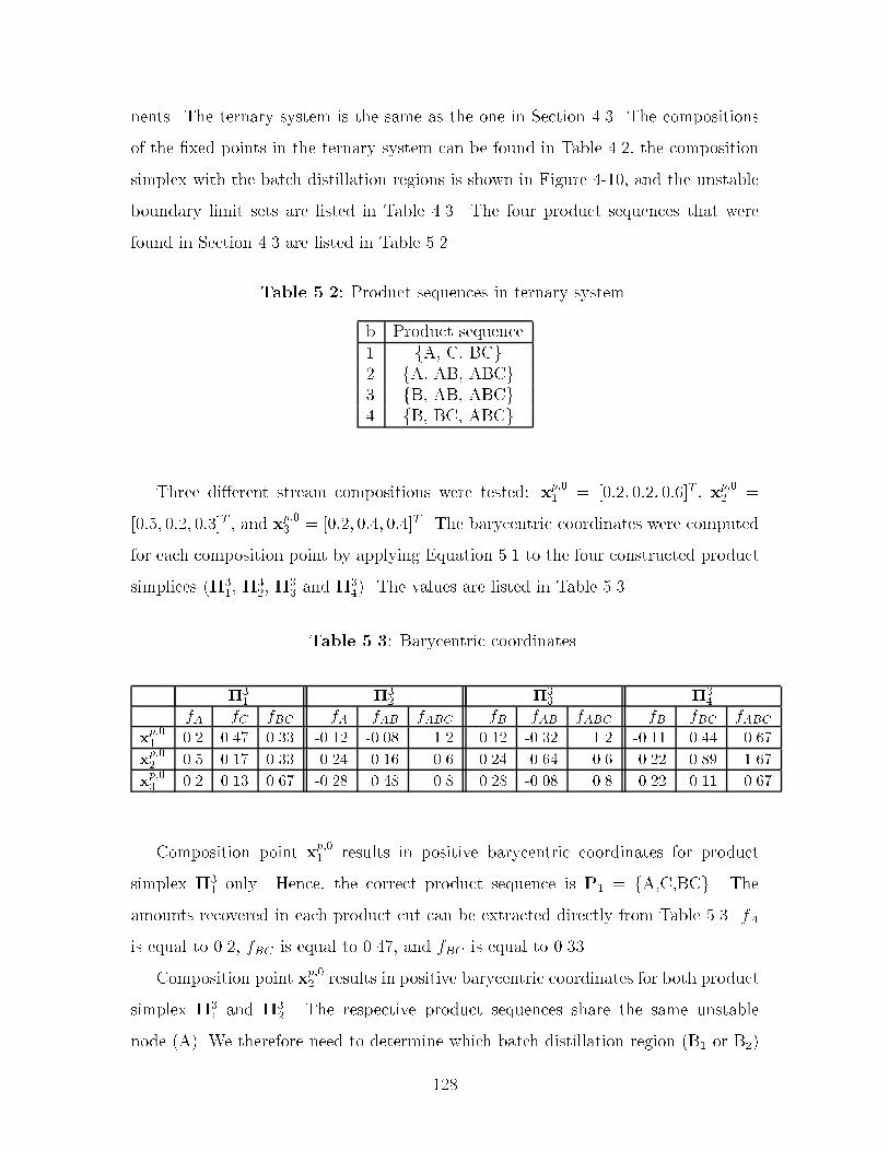
nents� The ternary system is the same as the one in Section ���� The compositions
of the �xed points in the ternary system can be found in Table ���� the composition
simplex with the batch distillation regions is shown in Figure ���� and the unstable
boundary limit sets are listed in Table ���� The four product sequences that were
found in Section ��� are listed in Table ����
Table ���� Product sequences in ternary system�
b Product sequence� fA� C� BCg� fA� AB� ABCg� fB� AB� ABCg� fB� BC� ABCg
Three dierent stream compositions were tested� xp��� � ����� ���� ����T � xp��� �
����� ���� ����T � and xp��� � ����� ���� ����T � The barycentric coordinates were computed
for each composition point by applying Equation ��� to the four constructed product
simplices ����� �
��� �
�� and ��
��� The values are listed in Table ����
Table ���� Barycentric coordinates�
��� �
�� �
�� �
��
fA fC fBC fA fAB fABC fB fAB fABC fB fBC fABC
xp��� ��� ���� ���� ����� ���� ��� ���� ����� ��� ����� ���� ����
xp��� �� ���� ���� ���� ���� ��� ����� ���� ��� ���� ��� ����
xp��� ��� ���� ���� ���� ��� �� ��� ���� �� ���� ���� ����
Composition point xp��� results in positive barycentric coordinates for product
simplex ��� only� Hence� the correct product sequence is P� � fA�C�BCg� The
amounts recovered in each product cut can be extracted directly from Table ���� fA
is equal to ���� fBC is equal to ����� and fBC is equal to �����
Composition point xp��� results in positive barycentric coordinates for both product
simplex ��� and ��
�� The respective product sequences share the same unstable
node �A�� We therefore need to determine which batch distillation region �B� or B��
��

contains the active batch distillation boundary� The relative distance to the boundary
may be computed using Equation ������ Alternatively� Equation ����� may be applied
directly to the barycentric coordinates for the �rst product cut� From Table ��� we
�nd that f �A � ���� while f �
A � ����� Consequently� batch distillation region � contains
the active batch distillation boundary� and xp��� will give rise to product sequence P� �
fA�AB�ABCg� The fractions recovered of each product cut can be extracted directly
from Table ���� fA is equal to ����� fAB is equal to ����� and fABC is equal to ����
Composition point xp��� results in positive barycentric coordinates for both product
simplex ��� and ��
�� The respective product sequences do not share the same unstable
node� Product sequence P� has pure component A has its �rst product cut� while
product sequence P� has pure component B has its �rst product cut� We therefore
need to determine which batch distillation region �B� or B�� that has the unstable
node on the same side of the stable dividing boundary as stream composition xp��� �
This is done by performing the steps in Section ������
The common unstable boundary limit set is determined from Table ��� using
Equation ����� in Chapter ��
�uc�A�B� � fC� AB� BC� ABCg � fAB� BC� ABCg � fAB� BC� ABCg �����
The stable dividing boundary is approximated by the two product simplex bound
aries "��� de�ned by "P� � fAB� ABCg� and "��
� de�ned by "P� � fBC� ABCg� Hence�
two new �simplices are generated by adding A as the �rst vertex� de�ned by the
vertices Sa � fA� AB� ABCg� and Sb � fA� BC� ABCg� The barycentric coordinates
are computed for these new simplices for xp��� � The values are shown in Table ����
Table ���� Barycentric coordinates for xp��� �
��� Simplex a Simplex b
fA fC fBC fA fC fBC fA fC fBC
xp��� ��� ���� ���� ���� ��� �� ��� � �� ����
Simplex a has some negative barycentric coordinates� We therefore only need to
���

compute the relative distances �Asdb�b and �Appb� This is done by applying Equation
������
�Asdb�b ��
�� ������ ��� ��� �
�Appb ��
�� ���� ���� �����
�Asdb�b � �Appb� Hence� xp��� is not located in batch distillation region �� Con
sequently� it must be located in batch distillation region �� For completeness� the
procedure is repeated for unstable node B�
Two new �simplices are generated by adding unstable node B as the �rst vertex�
de�ned by the vertices Sc � fB� AB� ABCg� and Sd � fB� BC� ABCg� The barycentric
coordinates are computed for these new simplices for xp��� � The values are shown in
Table ����
Table ���� Barycentric coordinates for xp��� �
��� Simplex c Simplex d
fB fBC fABC fB fBC fABC fB fBC fABC
xp��� ���� ���� ���� ��� ���� �� ���� ���� ����
Simplex c has some negative barycentric coordinates� We therefore only need to
compute the relative distances �Bsdb�d and �Bppb� This is done by applying Equation
������
�Bsdb�d ��
�� ����� ��� ������
�Bppb ��
�� ����� ��� ������
�Bsdb�d � �Bppb� Hence� the result above is con�rmed� The fractions recovered in
each product cut can be extracted directly from Table ���� fB is equal to ����� fBC is
equal to ����� and fABC is equal to ����� For clarity the locations of the composition
points in the composition simplex are shown in Figure ����
���

•
•
2
3
41
TBBC, 5
TB6
ABC
TB4AB,
TB1A,
TB2B,TB
3C,
+
++
x3p,0
x2p,0
x1p,0
Figure ���� Locations of the composition points in the composition simplex�
� Siloxane Monomer Process
Solvent recovery targeting is applied to the production of a siloxane based monomer
in a single campaign �Figure ����� The process consists of several sequential reaction
steps� Solvents and reaction byproducts are separated from products through batch
distillation� Further details concerning the process can be found in Allgor et al� �������
The dierent unit operations were simulated using ABACUSS�� The azeotropic be
havior was approximated using the Wilson model to calculate the activity coe�cients
�see� for example� Reid et al� ��� ���� Binary parameters were extracted from Aspen
Plus �Aspen Technology� ������ Missing binary parameters were estimated using the
UNIFAC group contribution method �Fredenslund et al�� ����� as implemented in
Aspen Plus �Aspen Technology� ������ Binary parameters for the pairs involving
the nonstandard components R�� C� E� A� and D can be found in Appendix D� R�
represents allyl alcohol� The vapor phase was assumed to be ideal� A batch size
of � � kg of product �A � D� was used as a basis for the simulations� The stream
compositions for the base case are summarized in Appendix C�
There are two mixed wastesolvent streams generated in the process� Firstly� the
�ABACUSS �Advanced Batch and Continuous Unsteady�State Simulator� Process Modeling Soft�ware� a derivative work of gPROMS Software� Copyright ���� by the Imperial College of Science�Technology and Medicine�
���

Rectifier III
D, A
Reactor I Reactor II
R1, R2, Toluene
Pt
Rectifier I
Methanol
Rectifier II Reactor III
Pt, I2
H2O, Methanol, Toluene, E
H2O
E, A, Toluene
R1, Methanol, Toluene, EH2
R1 + R2R1 + I1
I1C + I1
Pt
I1 (Pt catalyzed)AC + H2I2Pt*
2 E + H2O D + 2 MeOHC + MeOH E
1
2
34
5 6/7
8
9
10
11
12
13
14
15
Figure ���� Siloxane monomer process� base case
stream leaving overhead from the �rst recti�er contains large amounts of toluene �T�
and methanol �M�� about ��� of the reactant R�� and small amounts of the inter
mediate E� The composition simplex for this system divided into batch distillation
regions is presented in Figure ���� E is not included as there is very little of this
intermediate present in the stream� Also� E does not form an azeotrope with any of
the other components� The mixture exhibits a lowboiling binary azeotrope between
methanol and toluene �MT�� and a lowboiling binary azeotrope between toluene and
R� �R�T�� There are three batch distillation regions present� each resulting in dif
ferent product sequences with three cuts� P� �fMT�M�R�g� P� �fMT�R�T�R�g�
and P� �fMT�R�T�Tg� In this case the generated product simplices coincide with
their respective batch regions� The initial composition places the stream in region
�� At the limit� � � or about ��� kmol will be recovered as the methanoltoluene
azeotrope� ��� or about ���� kmol as the R�toluene azeotrope and � � or ��� kmol
as pure toluene� Hence only toluene can possibly be recovered as a pure component�
Provided that the fraction of methanol in the R�toluene cut is very small� this cut
could probably be recycled back to reaction step I� To avoid premature reaction of C
with methanol� methanol may not enter reaction step I� In addition� recycling of the
methanoltoluene azeotrope to reaction step II will result in unacceptable buildup
of toluene� Therefore� at least � � of this stream �the methanoltoluene azeotrope�
could not be recovered� In other words� at least � � of the stream would end up as
organic waste�
���
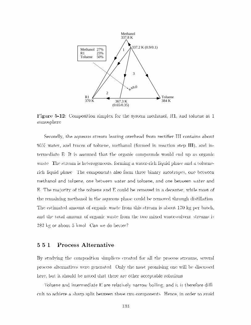
Methanol337.8 K
337.2 K (0.9/0.1)
Toluene384 K 367.3 K
(0.65/0.35)
R1370 K
1
2
3
MethanolR1Toluene
27%23%50%
+xp,0
Figure ���� Composition simplex for the system methanol� R�� and toluene at �atmosphere�
Secondly� the aqueous stream leaving overhead from recti�er III contains about
��� water� and traces of toluene� methanol �formed in reaction step III�� and in
termediate E� It is assumed that the organic compounds would end up as organic
waste� The stream is heterogeneous� forming a waterrich liquid phase and a toluene
rich liquid phase� The components also form three binary azeotropes� one between
methanol and toluene� one between water and toluene� and one between water and
E� The majority of the toluene and E could be removed in a decanter� while most of
the remaining methanol in the aqueous phase could be removed through distillation�
The estimated amount of organic waste from this stream is about ��� kg per batch�
and the total amount of organic waste from the two mixed wastesolvent streams is
� � kg or about � kmol� Can we do better$
����� Process Alternative
By studying the composition simplices created for all the process streams� several
process alternatives were generated� Only the most promising one will be discussed
here� but it should be noted that there are other acceptable solutions�
Toluene and intermediate E are relatively narrow boiling� and it is therefore di�
cult to achieve a sharp split between these two components� Hence� in order to avoid
���

loss of intermediate E� a large fraction of toluene is left in the reboiler at the end
of distillation I� and� consequently� toluene will remain with the product and not be
removed until distillation III� This complicates solvent recovery since toluene forms
a binary azeotrope with methanol� It was therefore proposed to introduce a batch
distillation column between reaction step I and II as indicated in Figure ���� Three
product cuts were proposed� Intermediate C is recovered for reaction step II� toluene
and excess reactants are recycled back to reaction step I� and product A is puri�ed�
Methanol and C are recovered in recti�er II� and recycled directly back to reactor
II� No toluene is carried through to the last column� The aqueous waste stream is
therefore only contaminated with methanol which will greatly simplify the cleanup of
the stream� The stream composition is about �� kmol water and ��� kmol methanol�
All the toluene is recovered and recycled� and there will be no toluene losses from
the process� In fact� since the excess methanol from reaction step II is recycled�
only the methanol generated in reaction step III ���� kmol� and removed in a water
treatment facility will appear as organic waste� The total amount of organic waste is
reduced by approximately ��� compared to the base case� Other improvements are
also achieved� raw material is saved� and the load on downstream units is reduced�
Rectifier III
D
Reactor I Reactor II
C + MeOH ERectifier I
R1, R2, Toluene
Pt
Methanol
Rectifier II Reactor III
Pt, I2
H2O, Methanol
H2O
C, Methanol
H2
R1 + R2R1 + I1
I1C + I1
Pt
I1 (Pt catalyzed)AC + H2I2Pt*
2 E + H2O D + 2 MeOH
Cut 2: R1, I1, Toluene, C
Cut 3: A
Cut 1: C
E
Figure ���� Process alternative
An analysis of the new composition simplex for the ternary system C� R�� and
toluene indicates that there are two batch distillation regions from which intermediate
C can be recovered as a pure species �see Figure �����
���
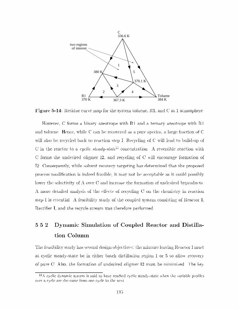
Toluene384 K367.3 K
R1370 K
1
2
3
C336.6 K
380 K
370.1 K
5
4
two regions of interest
Figure ���� Residue curve map for the system toluene� R�� and C at � atmosphere�
However� C forms a binary azeotrope with R� and a ternary azeotrope with R�
and toluene� Hence� while C can be recovered as a pure species� a large fraction of C
will also be recycled back to reaction step I� Recycling of C will lead to buildup of
C in the reactor to a cyclic steady�statezz concentration� A reversible reaction with
C forms the undesired oligmer I�� and recycling of C will encourage formation of
I�� Consequently� while solvent recovery targeting has determined that the proposed
process modi�cation is indeed feasible� it may not be acceptable as it could possibly
lower the selectivity of A over C and increase the formation of undesired byproducts�
A more detailed analysis of the eects of recycling C on the chemistry in reaction
step I is essential� A feasibility study of the coupled system consisting of Reactor I�
Recti�er I� and the recycle stream was therefore performed�
����� Dynamic Simulation of Coupled Reactor and Distilla
tion Column
The feasibility study has several design objectives� the mixture leaving Reactor I must
at cyclic steadystate be in either batch distillation region � or � to allow recovery
of pure C� Also� the formation of undesired oligmer I� must be minimized� The key
zzA cyclic dynamic system is said to have reached cyclic steady�state when the variable pro�lesover a cycle are the same from one cycle to the next�
���

design variables are the charge and temperature policies for the reactor which will
control the amount of solvent and reagent at the end� the concentration of I�� and
hence I��
A dynamic model of the reactor and the column was created to predict the buildup
of C in this recycle loop at cyclic steadystate �see Figure ����� The coupled reactor
distillation system was modeled using ABACUSS and applying the same models as
in the base case calculations� Only the operating policies were modi�ed� In the base
case all of R�� R�� toluene� and platinum catalyst was charged at the same time� The
mixture was heated to its boiling temperature� The heating jacket was then turned
o and the exothermic reaction was allowed to continue until the amount of R� or
R� was less then ��� mol� Once this criteria was met� the reaction was considered
complete�
H2
A
CR1, I1, C, toluene
R1, R2, toluene Pt
Pt, I2Rectifier IReactor I
R1 + R2R1 + I1
I1C + I1
Pt
I1 (Pt catalyzed)AC + H2I2Pt*
Figure ���� Model of coupled reactor and distillation column�
In the modi�ed process all of R� and toluene was charged initially� The mixture
was heated to its boiling temperature and the heating jacket was turned o� The
catalyst slurry was then added� Over the next two hours R� was charged continuously
to maintain a high R��R� ratio� This feed policy favors formation of A over C� The
reaction was allowed to continue until the amount of R� or R� was less then ���
mol� In the subsequent cycles a stream consisting of R�� toluene� and C and small
amounts of I�� R�� and A was recycled from the distillation column� The recycle
���

stream signi�cantly decreased the amount of fresh R� and toluene needed�
The composition pro�le in reaction step I reached cyclic steadystate after four
cycles� Only a slight increase in the fraction of C was observed� while the fraction of
A consequently was reduced with a similar amount� At cyclic steadystate ���� kmol
of C and ���� kmol of A were produced� compared to �� � kmol of C and ��� kmol
of A in the base case� No noticeable increase in the fraction of I� was detected� The
holdup in reaction I over three cycles is shown in Figure ����
C [MOL]
R1 [MOL]
TOLUENE [MOL]
A [MOL]
I2 [MOL]
R2 [MOL]
I1 [MOL]
CAT [MOL]
DCAT [MOL]
Molar Holdup x 103
3Time x 10
0.00
0.50
1.00
1.50
2.00
2.50
3.00
3.50
4.00
4.50
5.00
5.50
6.00
6.50
7.00
7.50
8.00
0.00 20.00 40.00 60.00 80.00 100.00
Figure ���� Holdup in reaction step I over three cycles�
The coupled reactor and distillation model was extremely valuable in designing
integrated operating policies for the reaction and the distillation task to minimize the
formation of I�� and also to ensure that the mixture to be separated remains in the
���

composition region from which C can be recovered as a pure species�
� Production of a Carbinol
Solvent recovery targeting was applied to the production of a carbinol ��methyl�H
dibenzo�a�d�cycloheptene�ol� �see Figure ����� The synthesis represents one of the
�� steps in a manufacturing process for the production of �methyl�����dihydro�H
dibenzo�a�d�cycloheptene�����imine�maleate�
REACTION
Carbinol
Cyclohexane
Diethyl EtherTHFCyclohexaneCyclohexane
Acetic-Acid/Water
Aqueous phase Aqueous waste
TrienoneCH3MgBr / Diethyl Ether
Brine
THF
MIXING QUENCH WASHING EVAPORATION CRYSTALLIZATION
1
23
4
5
6
7
9
10
8
12
11
13
14
15
16
Figure ���� Flowsheet for production of a carbinol�
The process consists of a reaction step followed by quenching with an aqueous
solution and a twophase separation� and washing with brine� Then the reaction
solvent is replaced by the crystallization medium through evaporation� and the prod
uct is crystallized and collected through �ltration� In the reaction step trienone is
converted to carbinol� A major impurity is tetraene� produced by acid catalyzed
elimination of carbinol� Further details about the process can be found in Aumond
������ and Linninger et al� ������� The azeotropic behavior was approximated using
the NRTL �NonRandomTwoLiquid� model �Renon and Prausnitz� ��� � to cal
culate the activity coe�cients� Binary parameters were extracted from Aspen Plus
�Aspen Technology� ������ A batch size of ��� kg of carbinol was used as basis for
the study� The stream compositions for the base case are summarized in Appendix
E�
The major organic waste stream results from the replacement of the reaction
medium tetrahydrofuran �THF� with crystallization medium cyclohexane� The sol
vent switch takes place through evaporation� and the resulting waste stream is a
��

ternary mixture consisting of about ���� kmol of diethyl ether ������ ���� kmol
of THF �������� and � � kmol of cyclohexane �������� It is desirable to recover
the solvents for reuse through batch distillation� The composition simplex for this
mixture at � atmosphere is shown in Figure �� � Cyclohexane and THF exhibit
a lowboiling binary azeotrope� Varying the pressure reveals that the azeotrope is
not very pressure sensitive� Running the separation at lower pressure therefore does
not provide any signi�cant bene�ts� The pure component diethyl ether is the only
unstable node� and the two batch distillation regions will both give rise to diethyl
ether as the �rst product� followed by the binary azeotrope� Depending on the loca
tion of the initial composition the �nal cut will be either pure cyclohexane or pure
tetrahydrofuran� The initial composition places the mixed wastesolvent stream in
region �� and therefore diethyl ether ����� kmol� and cyclohexane ������ kmol� can
be recovered as pure components and reused� while THF will be recovered as part of
the azeotrope ����� kmol�� Since cyclohexane is the crystallization medium� recy
cling the recovered binary azeotrope to the reactor may cause some of the product
to crystallize prematurely� The fraction of cyclohexane in the azeotrope is relatively
small and may not cause a problem� However� if premature crystallization is not
acceptable the binary azeotrope has to be disposed of or possibly be split using an
entrainer� an alternative that is not considered here� In that case� the base case will
result in at least �� kmol or about ���� kg of organic waste per batch� Moving the
composition of the mixed wastesolvent stream to region � by adding tetrahydrofuran
and achieving recovery of pure THF would result in the same problem� as recovery
of the azeotrope cannot be avoided� In addition� the binary azeotrope and THF are
very close boiling� making it almost infeasible to obtain a sharp split�
The most promising option for process improvement lies in replacing THF with a
solvent that allows for easier recovery� It is also advantageous to replace THF because
it is miscible with water at atmospheric conditions �Wisniak� �� ��� and solvent is
often lost to the aqueous phase� Other problems associated with THF include its
extreme �ammability and the potential for formation of peroxides �Molnar� ������
Several issues have to be kept in mind when evaluating alternative solvents�
���

•Cyclohexane353.79 K THF
339.12 K339.04 K(0.927/0.075)
Diethyl Ether307.54 KP = 1 atm.
Diethyl Ether 10.0%THF 33.3%Cyclohexane 56.7%
+
1
2
Figure ��� Composition simplex for the system diethyl ether� tetrahydrofuran�and cyclohexane�
�� it must be compatible with the process chemistry
�� it should preferably be completely or partially immiscible with water to utilize
a twophase split to remove salts from the organic phase
�� it should preferably be less harmful than the replaced solvent� THF
The reaction is a Grignard addition� Ethers are usually employed as Grignard
reaction media� due to the ether group that is attracted by the highly electrophilic
magnesium atom in the Grignard compound� An obvious choice in this case is to
employ diethyl ether since it is already used as storage medium for the Grignard
compound� Diethyl ether is also suggested by Reichardt ��� � as a common solvent
for Grignard reactions� Diethyl ether is partially immiscible with water �Wisniak�
�� �� and will form the organic rich phase following the twophase split� Further
more� the replacement of cyclohexane through evaporation will result in a binary
solvent waste stream of diethyl ether and cyclohexane� Returning to the composition
simplex in Figure �� reveals that diethyl ether can be easily separated from cyclo
hexane� resulting in complete recovery of solvents� However� it is expected that the
use of diethyl ether will reduce the reaction rate� as the nucleophilic ether group in
diethyl ether may not be as e�cient as in THF due to the molecule s linear structure�
���

Laboratory experiments are necessary to resolve this issue�
Another possibility is to replace THF with a novel solvent replacement� For ex
ample� Molnar ������ designs and synthesizes a new class of solvents having similar
properties to THF� but which are nonvolatile and can be easily recovered from pro
cess streams using simple mechanical separation operations such as ultra�ltration�
The polymer solvent system is generated by attaching THF to a polymer backbone
and dissolving it in a relatively benign continuous phase� In the example process the
polymer based solvent can be recovered from the organic product stream after the
washing operation� leaving the product �carbinol� dissolved in the inert solvent� The
inert solvent is then replaced by cyclohexane through evaporation as in the base case�
Thus� we are again left with a mixed solventwaste stream consisting of diethyl ether�
cyclohexane� and the inert solvent that needs to be analyzed� Molnar ������ tests
dierent compositions of mixtures of toluene� hexane� and heptane as candidates for
the inert continuous phase� Liquidliquid phase diagrams in Wisniak ��� �� show
that these three components are all almost completely immiscible in water� Apply
ing solvent recovery targeting discloses that none of the components form azeotropes
with diethyl ether or cyclohexane� Consequently� separating the solventwaste mix
ture through batch distillation would be relatively easy� and again no unnecessary
organic waste is generated� Laboratory experiments should be performed to deter
mine which of the candidate solvents �or mixture of� would result in the optimal
reaction conditions� The resulting �owsheet indicating solvent recovery and recycling
is shown in Figure ����
�� Summary
The algorithm for constructing the batch distillation composition simplex for a system
with an arbitrary number of components has been exploited in a sequential design
approach where process streams or mixed wastesolvent streams are analyzed for
maximum feasible solvent recovery using a targeting approach� The procedure is
termed solvent recovery targeting� For a given base case� solvent recovery targeting
���
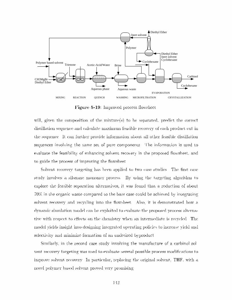
REACTION
Carbinol
Cyclohexane
Diethyl EtherInert solventCyclohexane
Cyclohexane
EVAPORATION
CRYSTALLIZATION
Acetic-Acid/Water
Aqueous phase Aqueous waste
Trienone
CH3MgBrDiethyl Ether
BrinePolymer based solvent
MIXING QUENCH WASHING MICROFILTRATION
Diethyl Ether
Polymer
Inert solvent
Figure ���� Improved process �owsheet�
will� given the composition of the mixture�s� to be separated� predict the correct
distillation sequence and calculate maximum feasible recovery of each product cut in
the sequence� It can further provide information about all other feasible distillation
sequences involving the same set of pure components� The information is used to
evaluate the feasibility of enhancing solvent recovery in the proposed �owsheet� and
to guide the process of improving the �owsheet�
Solvent recovery targeting has been applied to two case studies� The �rst case
study involves a siloxane monomer process� By using the targeting algorithm to
explore the feasible separation alternatives� it was found that a reduction of about
��� in the organic waste compared to the base case could be achieved by integrating
solvent recovery and recycling into the �owsheet� Also� it is demonstrated how a
dynamic simulation model can be exploited to evaluate the proposed process alterna
tive with respect to eects on the chemistry when an intermediate is recycled� The
model yields insight into designing integrated operating policies to increase yield and
selectivity and minimize formation of an undesired byproduct�
Similarly� in the second case study involving the manufacture of a carbinol sol
vent recovery targeting was used to evaluate several possible process modi�cations to
improve solvent recovery� In particular� replacing the original solvent� THF� with a
novel polymer based solvent proved very promising�
���
Chapter �
Process�wide Design of Solvent
Mixtures
This chapter presents a systematic approach to the generation of batch process de
signs that have solvent recovery and recycling integrated into the �owsheet� The
design approach is based on the proposition that highly nonideal phase behavior� in
particular azeotropy� creates barriers to solvent recovery and recycling� and solvent
mixtures that cannot be recycled inevitably becomes toxic waste� The systematic
alteration of the mixtures formed in a batch process in order to facilitate solvent
recovery and recycling is therefore investigated� The primary objective is to design
the compositions of stream candidates that will �or can be� subject to recovery such
that the quantity of solvents crossing the plant boundary is minimized� subject to a
variety of constraints such as reaction stoichiometry� solvation of reactions� selectivity
achievable� etc�
The approach is realized as a mathematical programming problem� The advantage
of a mathematical programming formulation is that it facilitates the analysis and
integration of very complex networks where the tradeos are not obvious� For this
approach to be valuable� the model employed must be abstract but re�ect accurately
the complex physical behavior that drives the decision process �e�g�� azeotropy�� the
resulting mathematical program must be compact and solvable e�ciently for problem
sizes of industrial relevance� and the results must be generated in a form that can
���

be interpreted easily by the engineer to improve the process design� The formulation
presented satis�es all these criteria�
�� Problem Statement
The problem that is addressed can be stated as follows�
Given a set of reaction tasks with known stoichiometry and a set of ac�
ceptable solvent and entrainer candidates� synthesize a batch reaction and
separation network that satis�es production demand while integrating sol�
vent recovery and recycling in order to minimize waste generated�
The amount of waste generated is measured as the amount of material other than �nal
products that leave the process and cross the system boundary� Consequently� solvent
recovery and integrated recycling of the recovered material should be maximized�
However� unless the magnitudes of the recycled streams are restricted� they may
take on arbitrary values� This issue is illustrated by the example in Figure ���
The lost solvent �waste� is replaced through the makeup stream� The more solvent
is recovered and recycled� the less makeup is needed� until the maximum possible
amount of solvent is recovered and recycled and the level of waste has reached its
minimum� Beyond that the recycle stream may take on any value provided that the
total amount of solvent added to the reactor in each batch is su�cient to solvate the
reaction�
solvent make-up
products
lost solvent
reactants
recycled solvent
Figure ��� Recycling of solvent�
���

The optimization problem may therefore be formulated as an embedded optimiza
tion problem� where an inner optimization problem constraints the outer one �Clark
and Westerberg� �� ���
minXi�I
Freci
s�t� minXi�I
CiWi
�����
I represents the set of pure components� Freci is the amount of pure component i that
is recycled� Wi is the amount of component i that will end up as hazardous waste� and
Ci is a weighting factor� for example� representing the relative harm of component
i� or waste treatment cost� Hence� in the outer problem we attempt to minimize
the magnitude of the streams recycled subject to the constraints that any feasible
solution must be a minimum waste solution as measured by the weighting factors�
In general� the embedded optimization problem is very di�cult to solve� A spe
cial case of the embedded optimization problem is the multicriteria decision making
problem where several objective functions are optimized simultaneously� The solu
tion to this problem is a family of points called a pareto optimal surface or the set of
noninferior solutions� Each such solution has the property that it is not possible to
improve any of the objectives without simultaneously degrading the value of another�
As will be demonstrated in Chapter �� the structure of our design problem is such
that a sequential approach can be used to solve ������ First� the minimum level of
waste emitted to the environment is determined as measured by the weighting factors�
Second� the recycle �owrates are minimized subject to minimum waste emitted� In
fact� this feature also allows us to readily generate the pareto optimal surface by
specifying an acceptable level of waste� and then minimizing the recycle �ows� As
a �rst approximation� the magnitude of the streams entering the separation tasks
is assumed to be proportional to the cost of separating and recycling solvent� and
only material leaving a separation task can cross the system boundary� The objective
function can therefore be reformulated as�
���

minXd�D
Xi�I
FDindi
s�t� minXd�D
Xe� �E
CeFDwde
�����
where D is the set of separation tasks� FDindi is the �ow of component i into separation
task d� "E represent the set of product cuts �separated compositions� that will end up
as waste if they cross the system boundary� and FDwde is the amount of composition
e from separation task d crossing the system boundary�
The design approach is based on the derivation of a superstructure �Hwa� �����
Umeda et al�� ����� that embeds a large set of possible process con�gurations and sep
aration sequences� Streams may be mixed� split� and extra solvent or entrainer added�
Figure �� outlines the general modeling framework� It is composed of three compo
nents� the environment which serves as a source or sink for all material streams cross
ing the system boundary �e�g�� raw material� solvents� entrainers� products� waste��
a reactor block containing all reaction tasks in the process� and a separation block
containing all separation tasks in the process� Material leaving a reaction task may be
separated in a separation task or sent directly to the next reaction task� Recovered
material in a separation task may be sent upstream or downstream to a reaction task
or another separation task� or emitted to the environment�
Environment
Reactor Tasks Separation Tasks
System Boundary
Figure ��� General modeling framework�
���
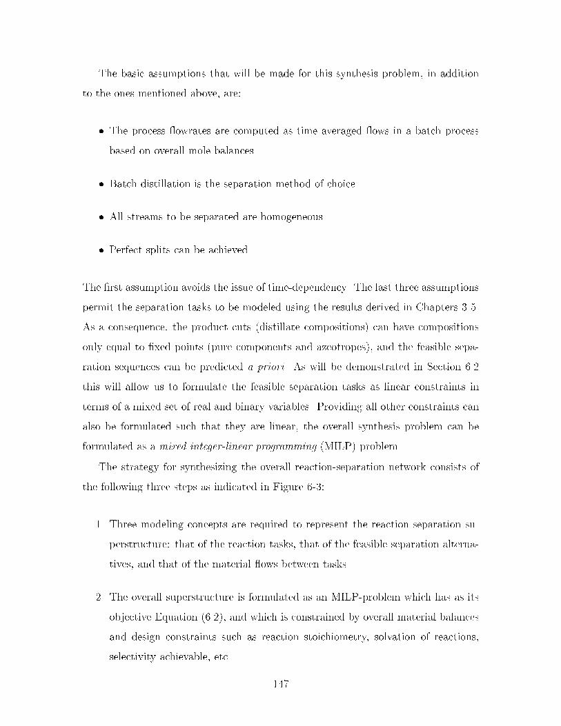
The basic assumptions that will be made for this synthesis problem� in addition
to the ones mentioned above� are�
� The process �owrates are computed as time averaged �ows in a batch process
based on overall mole balances�
� Batch distillation is the separation method of choice�
� All streams to be separated are homogeneous�
� Perfect splits can be achieved�
The �rst assumption avoids the issue of timedependency� The last three assumptions
permit the separation tasks to be modeled using the results derived in Chapters ���
As a consequence� the product cuts �distillate compositions� can have compositions
only equal to �xed points �pure components and azeotropes�� and the feasible sepa
ration sequences can be predicted a priori� As will be demonstrated in Section ���
this will allow us to formulate the feasible separation tasks as linear constraints in
terms of a mixed set of real and binary variables� Providing all other constraints can
also be formulated such that they are linear� the overall synthesis problem can be
formulated as a mixed integer�linear programming �MILP� problem�
The strategy for synthesizing the overall reactionseparation network consists of
the following three steps as indicated in Figure ���
�� Three modeling concepts are required to represent the reactionseparation su
perstructure� that of the reaction tasks� that of the feasible separation alterna
tives� and that of the material �ows between tasks�
�� The overall superstructure is formulated as an MILPproblem which has as its
objective Equation ������ and which is constrained by overall material balances
and design constraints such as reaction stoichiometry� solvation of reactions�
selectivity achievable� etc�
���

�� The solution to the MILPproblem will provide stream compositions to achieve
optimal separation sequences� stream �owrates� reaction conversions� selected
solvents and entrainers� and recycle stream structure�
Reaction-separation superstructure
Feasible separationsequences
Material flowbetween tasks
Reaction Tasks
MILP-formulation
Reaction-separation network
Figure ��� Strategy for the synthesis of the overall reactionseparation network�
�� Feasible Separation Sequences
A batch distillation region B is the set of compositions that leads to the same sequence
of product cuts P � fp��p�� � � �g upon distillation under the limiting conditions of
high re�ux ratio and large number of equilibrium stages �see De�nition �� in Chapter
��� Theorems �� and �� in Chapter � prove that under the assumptions of very high
re�ux ratio� large number of equilibrium trays� and linear pot composition boundaries
an nc component mixture will produce exactly nc product cuts �pure components
and�or azeotropes� �i�e�� P � fp��p�� � � � pnc��g�� and that these nc vertices bound
an �nc � ��simplex� Such a simplex is termed the product simplex ��P� of the
corresponding batch distillation region B�P��
A product simplex �nc for an nc component mixture can be characterized by the
��

set of vectors fpk � Rnc �k � �� � � � � nc� �g such that�
�nc � fx � Q � x �nc��Xk�
fkpk� fk � � �k � �� � � � � nc� � andnc��Xk�
fk � �g �����
where fk �k � �� � � � � nc � � are the barycentric coordinates� and Q is the whole
composition simplex� The element pki represents the molefraction of pure component
i in product cut k in the nc vector pk� Hence� if a point �x in the composition simplex
satis�es the condition for positive barycentric coordinates with respect to �nc then
�x � �nc�
From the de�nition of batch distillation regions it follows that if the initial com
position of interest xp�� is located in batch distillation region B�P�� the corresponding
product sequence P will result� Any point in B�P� must be a point in the corre
sponding product simplex de�ned by ��P�� xp�� therefore must satisfy Equations
����� with respect to ��P�� This can be con�rmed by solving the system of lin
ear equations above for f given xp��� p��p�� � � � �pnc�� and examining the values of
fk �k � �� � � � � nc � �� Physically� the scalars fk represent the fractions of xp�� that
will be recovered in each product cut through batch distillation� The fact that both
xp�� and the set of points fpk �k � �� � � � � nc� �g lie in the hyperplanePnc
i� xi � �
implies that the criteriaPnc��
k� fk � � is also satis�ed� If one or more fk � � this
implies that xp�� lies on one of the faces of ��P��
No loss of generality is induced by expressing Equations ����� on a mole basis�
When multiplying both sides by the total number of moles initially in the reboiler
�Fp��� Equations ����� take the form�
Fp�� �nc��Xk�
Fkpk� Fk � � �k � �� � � � � nc� � �����
Fp��i is the total number of component i initially in the reboiler� and Fk is the total
number of moles recovered in product cut k� The material balance con�rms thatPnc��k� Fk �
Pnci� Fp��
i � Fp���
Any composition in the composition space will yield a unique product sequence�
���

Unfortunately� since the batch distillation regions �ll the composition simplex� and a
product simplex will either coincide or be larger than its batch region� two or more
product simplices can possibly intersect� In that case two or more product simplices
will satisfy Equations ����� for the compositions in the intersection� This dilemma is
discussed in Chapter �� Criteria that can be used to distinguish intersecting product
simplices� and� hence� two batch distillation regions claiming the same initial compo
sition are provided� However� the mathematical formulation presented here assumes
that all product simplices coincide with their respective batch distillation regions
�category �a in Section ����� This is a reasonable assumption since systems that give
rise to intersecting product simplices are relatively rare� Given the initial composi
tion xp��� Equations ����� therefore provide us with a simple test for predicting the
correct separation sequence� For a composition simplex with NB batch distillation
regions NB linear equation systems as de�ned by Equations ����� can be generated�
By computing the barycentric coordinates for each region the correct product se
quence can be determined� xp�� is located in the batch distillation region that has all
Fk � � �k � �� � � � � nc � �� and hence will give rise to the corresponding product
sequence when batch distillation is employed�
�� Separation Superstructure
As argued above� when distilled an nc component mixture will give rise to at most nc
product �distillate� cuts� The product cuts can only have compositions equal to �xed
points� and the set of product cuts achieved is dependent on which batch distillation
region the feed composition is located� A distillation task can therefore be represented
as shown in Figure ��� The nodes �� �� � � �� ep represent �xed points in a system�
and hence are the known feasible product compositions achievable when employing
batch distillation� The �ows to each of the nodes will be greater or equal to zero�
Note that the pure component compositions in the system are a subset of the �xed
points� The �xed point nodes play a crucial role in the mathematical formulation�
and may be thought of as unlimited intermediate storage tanks�
���

1
2
3
ep
• •
•
D
Figure ��� Representation of distillation task in reactionseparation superstructure�
To demonstrate how the superstructure for feasible separations can be derived�
suppose that there is a mixture with three components� A� B� and C� and that
the composition simplex contains four �xed points �three pure components and one
azeotrope �AB�� and two batch distillation regions� The ternary residue curve map
is shown in Figure ��a� Batch distillation region � gives rise to sequence P� �
fp���p���p��g �fA�AB�Cg� and batch distillation region � gives rise toP� � fp���p���
p��g �fB�AB�Cg� The postulated superstructure for the distillation of this mixture
is then shown in Figure ��b�
2
1
A
AB
B C
a) b)A
B
AB
C
Distillation task
b = 1
b = 2
p12
p21
p22
p23
p11
p13
Figure ��� Superstructure of distillation task for a ternary mixture with oneazeotrope and two batch distillation regions�
���
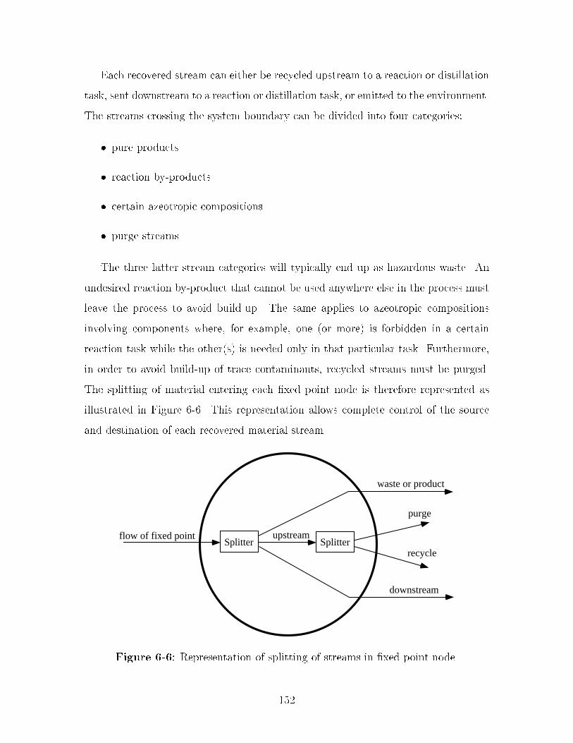
Each recovered stream can either be recycled upstream to a reaction or distillation
task� sent downstream to a reaction or distillation task� or emitted to the environment�
The streams crossing the system boundary can be divided into four categories�
� pure products
� reaction byproducts
� certain azeotropic compositions
� purge streams
The three latter stream categories will typically end up as hazardous waste� An
undesired reaction byproduct that cannot be used anywhere else in the process must
leave the process to avoid buildup� The same applies to azeotropic compositions
involving components where� for example� one �or more� is forbidden in a certain
reaction task while the other�s� is needed only in that particular task� Furthermore�
in order to avoid buildup of trace contaminants� recycled streams must be purged�
The splitting of material entering each �xed point node is therefore represented as
illustrated in Figure ��� This representation allows complete control of the source
and destination of each recovered material stream�
Splitter Splitter
waste or product
purge
recycle
upstream
downstream
flow of fixed point
Figure ��� Representation of splitting of streams in �xed point node�
���

�� Super Simplex
The notion of the composition simplex divided into a series of batch distillation regions
leads to the conception of a super simplex corresponding to the overall composition
simplex of mixtures of all the components that may appear in the process� This set of
components will include raw material and products� in addition to several candidate
solvents and entrainers� The super simplex will represent the search space for feasible
separation� Optimization in this super simplex may drive the mixtures formed in
the process to lower dimensional faces� thus choosing between candidate solvents�
or� alternatively� identify potential entrainers� The derivation of the super simplex
is based on the assumptions of high re�ux ratio� large number of trays� linear pot
composition boundaries� and homogeneous mixtures� and can be derived using the
algorithm in Chapter � for a given set of components�
� Reaction�Separation Superstructure
The overall reactionseparation superstructure is shown in Figure ��� Each reaction
task is assumed to be followed by a distillation task� However� the formulation allows
the optimization to omit the distillation task and let a reaction task feed directly to
the next reaction task� Each separation task is represented by a node for each �xed
point �see Figure ���� A �xed point node may only take input from the corresponding
separation task� and output to the environment� to all separation tasks� and to all
reaction tasks�
� Mathematical Formulation
To derive the mathematical formulation� the following index sets will be used to char
acterize the topology of the superstructure� The �xed points will be represented by
the index set E � feg� The set of pure components� which is a subset of E� will
be represented by I � fig� J � fjg represents the set of reaction tasks� The set
of reactions taking place in a particular reaction task is denoted by Rj � fg� The
���

System Boundary
Reaction Tasks
R1
R2
Rj
Separation Tasks
D1
D2
Dd
Environment
Figure ��� Reactionseparation superstructure�
distillation tasks are represented by D � fdg� In the mathematical formulation each
batch distillation region in the super simplex will be represented by its correspond
ing product simplex� NB � fbg denotes the batch distillation regions� Kb � fkg
denotes the individual product cuts� and Kbe denotes the set of product cuts in batch
distillation region b with composition equal to �xed point e�
Each reaction task is modeled as a simple extent reactor� The individual reactions
are speci�ed in terms of stoichiometry� The �ows into and out of reaction task j of
component i are given by FRinji and FRout
ji � Although FRoutj is a single stream� it is
represented by separate �owrates for each individual pure component� This is done in
order to avoid using molefractions� which would result in nonlinearities in the model�
The �ow of component i from reaction task j to reaction task "j is given by FRout
j�ji�
and the �ow of component i from reaction task j to distillation task d is given by
FRoutjdi � The �ow of material with composition equal to �xed point e from distillation
task d to reaction task j is given by FDRdje� and the �ow of material equal to �xed
���

point e from the environment to reaction task j is given by FEoutje � The overall mole
balances are de�ned by�
FRinji �
X��Rj
�j��j�i � FRoutji �j � J� i � I �����
FRinji �
Xe�E
SSie�Xd�D
FDRdje � FEoutje � � �����
X�j�J
FRout�jji �j � J� i � I
FRoutji �
X�j�J
FRout
j�ji �X�j�J
FRoutjdi �j � J� i � I �����
where �j�i is the stoichiometric coe�cient for component i in reaction in reaction
task j� The molar extent of reaction �j� is the same for all species taking part in
reaction � Note that for species that do not take part in reaction � �j�i � �� Hence�
FRinji � FRout
ji � The element SSie is the molefraction of component i in �xed point
e� which is data provided to the formulation� Also note that FRout
j�jimust be set to
zero for all reaction tasks "j that are not directly downstream to reaction task j� and
FRoutjdi � � for all distillation tasks d that are not directly downstream to reaction task
j� Likewise� FRout�jji
� � for all reaction tasks "j that are not directly preceding reaction
task j� The �ows in and out of reaction task j are shown in Figure � �
reaction task j reaction task
FRinj
FRoutjd
FRoutj j
j j 1
Figure �� Input and output �ows for reaction task j�
Following the discussion in Section ���� the material balance characterizing the
distillation of an nc component mixture can be expressed in terms of pbki� the mole
fraction of pure component i in product cut k from batch distillation region b� Flow
���
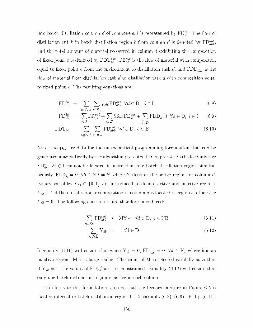
into batch distillation column d of component i is represented by FDindi � The �ow of
distillation cut k in batch distillation region b from column d is denoted by FDoutdbk�
and the total amount of material recovered in column d exhibiting the composition
of �xed point e is denoted by FDToutde � FEout
de is the �ow of material with composition
equal to �xed point e from the environment to distillation task d� and FDD �dde is the
�ow of material from distillation task "d to distillation task d with composition equal
to �xed point e� The resulting equations are�
FDindi �
Xb�NB
Xk�Kb
pbkiFDoutdbk �d � D� i � I ��� �
FDindi �
Xj�J
FRoutjdi �
Xe�E
SSie�FEoutde �
X�d�D
FDD�dde� �d � D� i � I �����
FDTde �X
b�NB
Xk�Kbe
FDoutdbk �d � D� e � E ������
Note that pbk are data for the mathematical programming formulation that can be
generated automatically by the algorithm presented in Chapter �� As the feed mixture
FDindi �i � I cannot be located in more than one batch distillation region simulta
neously� FDoutdbk � � �b � NB �� b� where b� denotes the active region for column d�
Binary variables Ydb � f�� �g are introduced to denote active and inactive regions�
Ydb � � if the initial reboiler composition in column d is located in region b� otherwise
Ydb � �� The following constraints are therefore introduced�
Xk�Kb
FDoutdbk � MYdb �d � D� b � NB ������
Xb�NB
Ydb � � �d � D ������
Inequality ������ will ensure that when Yd�b � �� FDout
d�bk� � �k � K�b where "b is an
inactive region� M is a large scalar� The value of M is selected carefully such that
if Ydb � �� the values of FDoutdbk are not constrained� Equality ������ will ensure that
only one batch distillation region is active in each column�
To illustrate this formulation� assume that the ternary mixture in Figure �� is
located internal to batch distillation region �� Constraints ��� �� ������ ������� �������
���

and ������ will then yield the �ows indicated in Figure ��b where the zero �ows are
not included�
A
AB
C
Distillation task
b = 1p12
p11
p13
FDoutd,1
FDoutd,11
FDoutd,13
FDoutd,12
FDToutd,A
FDToutd,C
FDToutd,AB
b = 1
b = 2
p12
p21
p22
p23
p11
p13
FDoutd,2
FDoutd,1
FDoutd,11
FDoutd,23
FDoutd,22
FDoutd,21
FDoutd,13
FDoutd,12
A
B
AB
C
Distillation task
FDind
FDToutd,A
FDToutd,C
FDToutd,AB
FDToutd,B
a) b)
FDind
Figure ��� Distillation of ternary mixture located in batch distillation region ��
Further� as Figure � shows the optimization can choose to omit a distillation
task and send material directly from one reaction task to the next� Binary variables
are therefore introduced to denote an active or inactive distillation task� Ld � � if
material is fed to distillation task d� otherwise Ld � �� The additional constraints
are�
Xi�I
FDindi � MLd �d � D ������
Inequality ������ will ensure that when Ld � �� FDindi � and� consequently� FRout
jdi are
zero�
The constraints that ensure overall mole balance around each �xed point node are
given by Equations ������� FEinde denotes �ow of �xed point e from distillation task d
to the environment� and PURGEde is the amount of purge with composition equal to
�xed point e from column d�
FDTde �Xj�J
FDRdje �X�d�D
FDDd �de � FEinde � PURGEde �d � D� e � E ������
The purge streams are computed using Equation ������� The choice of purge
���
fraction will depend on the purity requirements in the particular problem of interest�
PURGEde��� �de� �
�� Xj�Jdu
FDRdje �X
�d�Ddu
FDDd �de
�A �d � D� e � E ������
where Jdu represents the set of reaction tasks upstream of distillation task d� and
Ddu represents the set of distillation tasks upstream of distillation task d� Note
that Ddu includes the distillation task d itself� �de is the purge fraction of streams
with composition equal to �xed point e from column d� and is data provided to the
formulation� Typically� the same purge fraction is used throughout the formulation�
Finally� it must be required that all �owrates are nonnegative�
�� Stripper or Recti er Con guration
A batch stripper is con�gured in a similar manner to a batch recti�er� However� the
material is fed to the column from a holding tank where the mixture is held at its
boiling temperature by a condenser� The product is taken out at the bottom of the
column� and the recycled material is evaporated in a reboiler� Hence� the heaviest
species is separated o �rst� A more detailed discussion concerning the stripper
con�guration is provided in Appendix A�
When constructing the residue curve map for the mixture of interest� the arrows
indicating the direction of residue path should be reversed� as we will now be moving
from heavier to lighter species in the holding tank� Therefore� all residue curves will
reverse direction� As a result� the nodes that are unstable when a recti�er is assumed
will become stable� and vice versa for the stable nodes� From this point the analysis
is analogous to the analysis for a recti�er con�guration� based on the same limiting
assumptions of high re�ux ratio� large number of trays� and linear pot composition
boundaries� Batch distillation regions corresponding to a stripper con�guration can
therefore be constructed in a similar manner� providing new separation alternatives�
A choice between the two column con�gurations can be simply expressed as choos
ing between the total set of batch distillation regions� i�e�� NB � NBr NBs� and
��

constraints ��� �� ������ ������� ������� and ������ remain unchanged� NBr and NBs
represent batch distillation regions for the recti�er and the stripper con�guration�
respectively� Observe that it does not matter if members of these sets intersect in the
composition simplex� The optimization is simply choosing from two super simplices�
one which represents the separation alternatives when a recti�er con�guration is used�
and one which represents the separation alternatives when a stripper con�guration is
used� The mathematical model could be modi�ed in a similar manner to allow other
column con�gurations such as a middle vessel con�guration� provided that a means
of enumerating the product sequences and batch distillation regions is developed�
�� Other Constraints
In addition to constraints incorporating conservation of mass and feasible separations�
constraints speci�c to the chemistry and operation of a particular process are required�
Additional index sets are introduced to characterize these constraints� S � fsg is the
set of candidate solvents� and R � frg is the set of reagents� Categories of constraints
include�
� A lower bound on solvent to reagent ratio� Such constraints can be expressed
as�
FRinjs � RatiojsrFRin
jr ������
� Upper and lower bounds on extents of reaction� e�g�� minimum acceptable and
maximum feasible yield �Equation �������� or linear combinations of extents
yielding the range of selectivity achievable �Equations ���� � and ��������
LowerBoundj� � �j� � UpperBoundj� ������
�j� � RatioLowj����j� ���� �
�j� � RatioHighj����j� ������
���

� If the presence of a component causes undesired side reactions in a particular
reaction task� the �ow of this component either as pure species or as part of
an azeotrope to this reaction task should be forbidden� or the use of an upper
bound may be appropriate�
FRinji � UpperBoundji ������
Ratiojsr� LowerBoundj�� UpperBoundj�� RatioLowj���� RatioHighj���� and
UpperBoundji are scalars� Such data may be obtained through collaboration with
the chemist� through experiments or computer simulations�
�� Summary
A mixedinteger linear programming �MILP� formulation for the design of batch pro
cesses with integrated solvent recovery and recycling has been presented� A super
simplex is introduced� which corresponds to the overall composition simplex for mix
tures of several candidate solvents� and in general will contain multiple azeotropic
compositions� It is demonstrated that� under reasonable assumptions� the feasible se
quences of pure component and azeotropic cuts that can be separated from mixtures
in the super simplex can be formulated as linear constraints in terms of a mixed set
of real and binary variables� This result is especially signi�cant since it facilitates
a compact and e�cient mathematical abstraction of the complex azeotropic behav
ior that drives the decision process� For example� the choice of a particular solvent
corresponds to driving the mixture to a lower dimensional face of the super simplex�
The super simplex is embedded in a novel reactionseparation superstructure to
yield a modeling framework for the processwide design of the mixtures formed in
a batch process �primarily design of the mixtures leaving the reaction tasks�� The
modeling framework is �exible� new constraints can be easily added to produce more
realistic alternatives� and leads to a compact MILP that can be solved e�ciently to
guaranteed optimality� A very promising feature is the scalability of the formulation�
���

since the number of binary variables can be expressed roughly as the product of the
number of batch distillation regions with the number of distillation tasks embedded in
the super structure� The number of binary variables is a measure of the complexity of
the problem� and if this number grows slowly with process size it will greatly improve
the solvability of the problem� For example� the realistic industrial example solved
in the next chapter leads to an MILP probably two orders of magnitude smaller
than those that can be solved by current general purpose codes on a routine basis�
This enables us to be very ambitious with the problem formulations that can be
contemplated�
By its nature� the formulation is approximate and does not embed all constraints
on the design� Hence the engineer must interact with the formulation in an evolution
ary manner� the problem is �rst formulated as an MILP and an optimal �owsheet is
found� The methodology can then be employed to generate various designs by adding
or removing design constraints� thereby furnishing the engineer with a set of dierent
process designs that can be evaluated based on other criteria not embedded into the
program like reaction rates �which is a function of selected solvent�� production times�
safety� etc� The evolutionary character of the design approach is demonstrated in the
second case study in Chapter ��
���

���

Chapter
Optimization of a Siloxane
Monomer Process
The synthesis formulation for processwide design of mixtures has been applied to a
process for the production of a siloxane based monomer in a single campaign� The
process is the same as the one analyzed in Chapter � where an ad hoc method was
used to improve solvent recovery� In this chapter it is demonstrated that the process
can be further improved through use of an automated optimization procedure�
The �rst case study is a subsystem of the process and is used to illustrate the
concept of a super simplex to represent separation alternatives in combination with
mathematical programming� The second case study involves the entire process� The
mathematical programming formulation is used to generate several dierent process
alternatives by adding design constraints to the formulation� The process alternatives
generated show that an intuitive and automated formulation can produce minimum
emission designs very rapidly� Furthermore� it is veri�ed that the formulation can be
extended to explore the space of noninferior solutions corresponding to the tradeos
between quantity of waste emitted and the cost of recovering and recycling solvent�
��� Base Case
Figure �� shows the base case design from the pilot plant� Appendix C contains the
stream data� The process consists of several sequential reaction steps� Solvents and
���
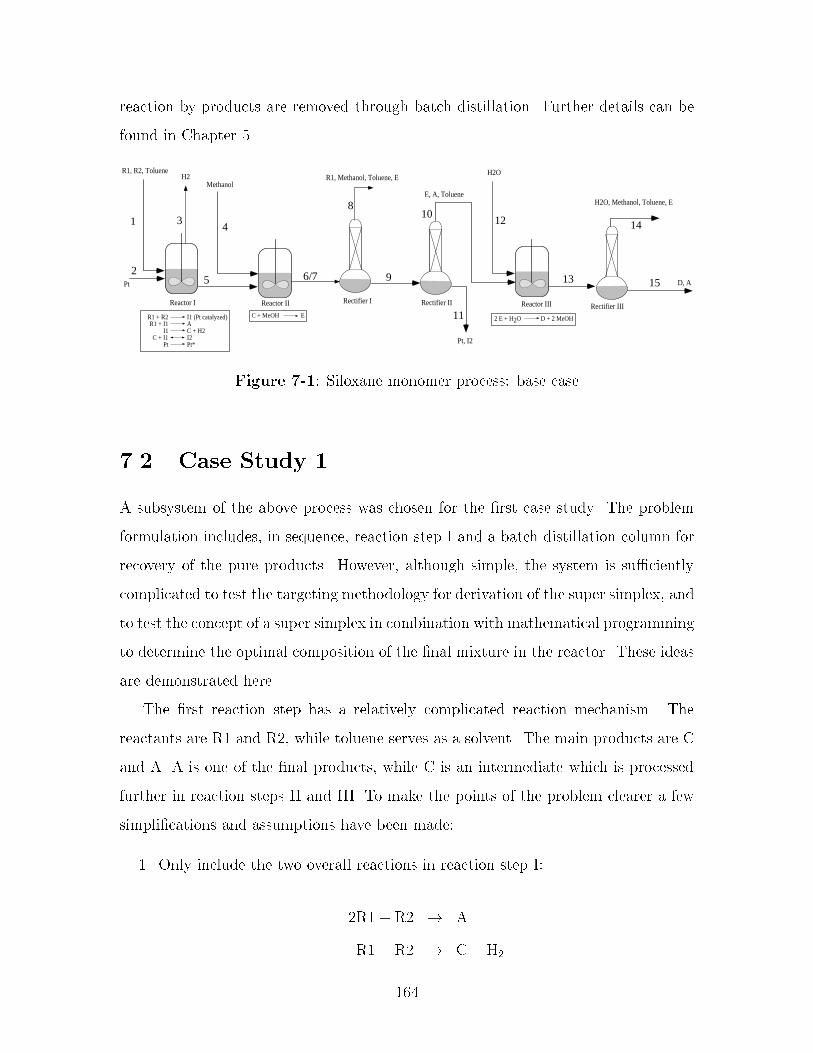
reaction byproducts are removed through batch distillation� Further details can be
found in Chapter ��
Rectifier III
D, A
Reactor I Reactor II
R1, R2, Toluene
Pt
Rectifier I
Methanol
Rectifier II Reactor III
Pt, I2
H2O, Methanol, Toluene, E
H2O
E, A, Toluene
R1, Methanol, Toluene, EH2
R1 + R2R1 + I1
I1C + I1
Pt
I1 (Pt catalyzed)AC + H2I2Pt*
2 E + H2O D + 2 MeOHC + MeOH E
1
2
34
5 6/7
8
9
10
11
12
13
14
15
Figure ��� Siloxane monomer process� base case
��� Case Study �
A subsystem of the above process was chosen for the �rst case study� The problem
formulation includes� in sequence� reaction step I and a batch distillation column for
recovery of the pure products� However� although simple� the system is su�ciently
complicated to test the targeting methodology for derivation of the super simplex� and
to test the concept of a super simplex in combination with mathematical programming
to determine the optimal composition of the �nal mixture in the reactor� These ideas
are demonstrated here�
The �rst reaction step has a relatively complicated reaction mechanism� The
reactants are R� and R�� while toluene serves as a solvent� The main products are C
and A� A is one of the �nal products� while C is an intermediate which is processed
further in reaction steps II and III� To make the points of the problem clearer a few
simpli�cations and assumptions have been made�
�� Only include the two overall reactions in reaction step I�
�R� � R� � A
R� � R� � C � H�
���

�� Run reaction step I to ���� conversion of R�� the most expensive reactant�
Any of the components can be accepted in a recycle stream� and the overall
material balance shows that only A and C need to leave the system� The total number
of moles of A and C produced is equal to the number of moles of R� converted� For
this particular setup� an appropriate objective would therefore be to minimize the �ow
of the recycled streams� while allowing only A and C to cross the system boundary�
���� Separation Sequences
There are �ve pure components in this system� However� as reaction step I is run to
extinction of R�� only four components will enter the batch distillation columns� hence
form the super simplex� These are C� R�� A� and toluene �T�� The azeotropic behavior
was approximated using the Wilson model to calculate the activity coe�cients �see�
for example� Reid et al� ��� ���� Binary parameters were extracted from Aspen
Plus �Aspen Technology� ������ Missing binary parameters were estimated using the
UNIFAC group contribution method �Fredenslund et al�� ����� as implemented in
Aspen Plus �Aspen Technology� ������ Binary parameters for the pairs involving the
nonstandard components C� and A can be found in Appendix D� R� represents allyl
alcohol� The vapor phase was assumed to be ideal� The components involved form
two binary azeotropes� one between R� and toluene� and one between C and R��
Components C� R�� and toluene also form a ternary azeotrope� Table ��� lists the
�xed points in the system at � atmosphere with compositions� boiling temperatures�
and whether a point is an unstable node �un�� stable node �sn�� or a saddle point �s��
The super simplex was generated using the algorithm described in Chapter � and
the feasible distillation sequences were extracted� There are �ve batch distillation
regions in the super simplex �see Figure ���� each producing � product cuts �see
Table �����
���

Table ���� Compositions� boiling temperatures� and stability of �xed points at �atmosphere� �� Since R� will not enter the column it is not included in the supersimplex�
e C R� R� T A TB�K� type
C � � � � � ����� unR� � � � � � ����� �R��T � � ��� ��� � ���� unR� � � � � � ����� sC�R��T ��� � ��� ��� � ����� sC�R� ���� � ��� � � ��� sT � � � � � ��� sA � � � � � �� sn
Toluene384 K
R1370 K
C336.6 K
A532 K
C-R1
R1-T
C-R1-T
Figure ��� Super simplex for C� R�� toluene� and A�
Table ���� Feasible distillation sequences for case study I�
b Product sequence� fC� CR�T� CR�� Ag� fC� CR�T� T� Ag� fR�T� R�� CR�� Ag� fR�T�CR�T� CR�� Ag� fR�T� CR�T� T� Ag
���

���� Formulation of Optimization Problem
The reactor should be operated such that there is stoichiometric excess of R� in order
to drive the reaction to completion� as speci�ed by the following constraint�
FRout��R� � ����FRin
��R� �����
We assume ���� conversion of R��
FRout��R� � � �����
This constraint can also be expressed in terms of the fractional conversion Xji� the
fraction of component i that is consumed in reaction task j� de�ned as�
Xji �FRin
ji � FRoutji
FRinji
�����
However� in order to avoid introducing nonlinearities the relationship should be writ
ten as�
XjiFRinji � FRin
ji � FRoutji �����
Constraint ����� is therefore enforced by specifying X��R� � �� A lower limit on
the ratio of solvent to reactant fed to the reactor is speci�ed in order to guarantee
adequate solvation�
FRin��R� � �����FRin
��T �����
In order to analyze selectivity to A versus C in the two parallel reactions the
dynamic behavior of the reactor was modeled using ABACUSS� The operating policies
were varied and the following upper and lower bounds on the relative extent of reaction
for the two parallel reactions� ���� and ����� respectively� were established�
���� � ��� ���� �����
���� � �������� �����
���
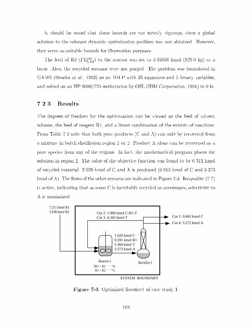
It should be noted that these bounds are not strictly rigorous� since a global
solution to the relevant dynamic optimization problem was not obtained� However�
they serve as suitable bounds for illustration purposes�
The feed of R� �FEout��R�� to the reactor was set to ���� �� kmol ������ kg� as a
basis� Also� the recycled streams were not purged� The problem was formulated in
GAMS �Brooke et al�� ����� as an MILP with �� equations and � binary variables�
and solved on an HP �������� workstation by OSL �IBM Corporation� ����� in ���s�
���� Results
The degrees of freedom for the optimization can be viewed as the feed of solvent
toluene� the feed of reagent R�� and a linear combination of the extents of reactions�
From Table ��� note that both pure products �C and A� can only be recovered from
a mixture in batch distillation region � or �� Product A alone can be recovered as a
pure species from any of the regions� In fact� the mathematical program places the
solution in region �� The value of the objective function was found to be ����� kmol
of recycled material� ���� kmol of C and A is produced ������ kmol of C and �����
kmol of A�� The �ows of the other streams are indicated in Figure ��� Inequality �����
is active� indicating that as some C is inevitably recycled as azeotropes� selectivity to
A is maximized�
Reactor I Rectifier I
7.211 kmol R13.938 kmol R2
2R1 + R2R1 + R2
AC
Cut 2: 1.969 kmol C-R1-TCut 3. 4.342 kmol T
Cut 4: 3.272 kmol A
Cut 1: 0.665 kmol C
SYSTEM BOUNDARY
1.020 kmol C0.591 kmol R15.366 kmol T3.273 kmol A
Figure ��� Optimized �owsheet of case study ��
��
��� Case Study �
The second case study involves all three reaction tasks in the siloxane monomer
process� Reaction step I was modeled as in the �rst case study� In reaction step II
intermediate C reacts with methanol �M� to form another intermediate E� Methanol
also serves as a solvent� In reaction step III E is converted to the second �nal product
D in a hydrolysis reaction� and methanol is a byproduct� In Chapter � an analysis
applying solvent recovery targeting to the waste streams emitted from the base case
reveals that the design will generate approximately � kmol of organic waste per batch�
���� Separation Sequences
As in the �rst case study� R� is not included in the super simplex� as this compo
nent will never enter a distillation column� Water and toluene are immiscible� and
therefore would lead to the formation of two liquid phases in certain regions of the
super simplex� Since the use of the super simplex is based on the assumption of
homogeneous mixtures� constraints preventing toluene and water from mixing are
required� Consequently� the optimized solution will move on the lower dimensional
faces of the super simplex omitting stream compositions containing both toluene and
water� and only product sequences on these faces are permitted� Two super sim
plices are therefore constructed� one representing the composition simplex formed by
the pure components C� M� R�� W� E� A� and D� and the other representing the
composition simplex formed by the pure components C� M� R�� T� E� A� and D�
It should be noted that the requirement to avoid heterogeneous mixtures places an
unnecessary restriction on our design� Heterogeneous mixtures appear frequently in
the class of processes we are studying� and an extension of the formulation to also
permit such mixtures is imperative in order to include all possible design alternatives�
The azeotropic behavior was approximated using the Wilson model to calculate the
activity coe�cients �see� for example� Reid et al� ��� ���� Binary parameters were
extracted from Aspen Plus �Aspen Technology� ������ Missing binary parameters
were estimated using the UNIFAC group contribution method �Fredenslund et al��
���

����� as implemented in Aspen Plus �Aspen Technology� ������ Binary parameters
for the pairs involving the nonstandard components C� R�� E� A and D can be found
in Appendix D� R� represents allyl alcohol� The vapor phase was assumed to be
ideal� Table ��� lists the �xed points in these two subsystems at � atmosphere with
compositions� boiling temperatures� and whether a point is an unstable node �un��
stable node �sn�� or a saddle point �s��
Table ���� Compositions� boiling temperatures� and stability of �xed points at �atmosphere�
e C M R� R� W T E A D TB�K� type
C�M ���� ���� � � � � � � � ����� unC � � � � � � � � � ����� sM�T � �� � � � ���� � � � ����� sM � � � � � � � � � ���� sR� � � � � � � � � � ����� �R��W � � � ��� ��� � � � � ���� sR��T � � � ��� � ��� � � � ���� sR� � � � � � � � � � ����� sW�E � � � � �� �� � ���� � � ���� sW � � � � � � � � � ����� sC�R��T ��� � � ��� � ��� � � � ����� sC�R� ���� � � ��� � � � � � ��� sT � � � � � � � � � ��� sE � � � � � � � � � ���� sA � � � � � � � � � �� sD � � � � � � � � � �� sn
The feasible distillation sequences were extracted from the two super simplices�
There are six batch distillation regions in the simplex containing water �� to � in
Table ����� and eight regions in the simplex containing toluene �� to �� in Table �����
Each of these regions involves seven components� Hence� each region produces seven
product cuts�
���� Formulation of Optimization Problem
In addition to the constraints introduced in the �rst case study governing reaction
step I� constraints governing reaction steps II and III were added� The conversion of
���

Table ���� Feasible product sequences for case study ��
b Product sequence� fCM� C� R�W� R�� E� A �Dg� fCM� C� R�W� WE� W� A �Dg� fCM� C� R�W� WE� E� A �Dg� fCM� M� R�W� R�� E� A �Dg� fCM� M� R�W� WE� W� A �Dg� fCM� M� R�W� WE� E� A �Dg� fCM� MT� M� R�� E� A �Dg fCM� MT� R�T� R�� E� A �Dg� fCM� MT� R�T� T� E� A �Dg�� fCM� C� CR�T� T� E� A� Dg�� fCM� C� CR�T� CR�� E� A� Dg�� fCM� R�T� CR�T� CR�� E� A� Dg�� fCM� R�T�CR�T� T� E� A� Dg�� fCM� R�T� R�� CR�� E� A� Dg
C to E was set to � ��
FRout��C � ����FRin
��C ��� �
Reaction step II takes place in excess methanol�
FRin��M � ����FRin
��C �����
Conversion of E was set to ���
FRout��E � ����FRin
��E ������
The hydrolysis reaction in step III takes place in large excess of water �W��
FRin��W � ��FRin
��E ������
In order to avoid buildup of trace contaminants� a purge fraction of ���� was
speci�ed� Furthermore� it was required that no water entered reaction step I and
II� no methanol entered step I� and no R� entered reaction step III� The feed of R�
���

�FRinR�� to reaction step � was set to ���� kmol as a basis� The problem was solved
in a sequential manner� First� the objective function was formulated as minimizing
the amount of waste emitted to the environment computed as the total �ow crossing
from the system to the environment of all �xed points except the �nal products
�A and D�� However� this problem has a nonunique solution� The recycle �owrates
can take on arbitrary values unless additional constraints are introduced� Therefore�
the optimal design was found by formulating a second optimization problem where
the recycle �owrates were minimized subject to minimum waste as found in the �rst
optimization problem� The problem was formulated in GAMS �Brooke et al�� ����� as
an MILP with ��� equations and �� binary variables� and solved on an HP ��������
workstation by OSL �IBM Corporation� ����� in ����s�
���� Results
The optimized �owsheet is shown in Figure ��� There is no separation between
reaction step I and II� The feed to recti�er I is placed in the subsystem C� M� R�� T�
E� and A in region � and the feed to recti�er II is located in the subsystem M� W� E�
A� and D in region �� Pure E and A recovered in recti�er I are fed to reaction step III�
The binary azeotrope CM and the binary azeotrope MT are recovered and recycled
to reaction step II� while the binary azeotrope R�T and pure toluene are recovered
and recycled to reaction step I� Pure water and the WE azeotrope are recovered in
recti�er II and recycled to reaction step III� Methanol generated in reaction step III
is recovered and recycled to reaction step II� ���� mol of product A and ��� mol
of product D are recovered in recti�er II� The amount of waste emitted is � � mol
resulting only from the purge streams� This is a reduction of about ��� compared
to the base case� Hence� embedding the super simplex in the reactionseparation
synthesis formulation has resulted in a design without azeotropic mixtures that cannot
be recycled� and therefore would become hazardous waste� Furthermore� since the
consumption of methanol in reaction step I balances the generation of methanol in
reaction step III� and methanol can be recovered in pure form in recti�er II� there is
no net production of undesired byproducts�
���

Reactor I2R1 + R2
R1 + R2AC
665 mol C 591 mol R1 5395 mol T 3273 mol A
7223 mol R13938 mol R2 110 mol T
SYSTEM BOUNDARY
Reactor IIRectifier I
C + M E
1615 mol M-T 20 mol C-M
14 mol C 1472 mol M 665 mol E 591 mol R1 5573 mol T 3272 mol A
Reactor IIIRectifier II
2E + W D + 2M
1333 mol W-E17917 mol W
664 moles M 19.2 kmoles W 117 moles E 3272 moles A 331 moles D
665 mol E3272 mol A
3272 mol A 331 mol D
650 mol M
Purge: 132 mol M-T 18 mol R1-T 100 mol T
Purge: 13 mol M 27 mol W-E
44 mol M 356 mol W
891 mol R1-T 4974 mol T
Figure ��� Case study �� optimized �owsheet�
The tradeo of recovery cost versus waste generated may also be studied� The
special properties of this problem allows us to readily generate the pareto optimal
surface �Clark and Westerberg� �� �� of this bicriteria optimization problem� This
is because the MILP can be solved to guaranteed global optimality� As a �rst ap
proximation� the magnitude of the recycled streams is assumed to be proportional
to the cost of separating and recycling solvent� The pareto optimal surface is then
generated by minimizing the recycle �owrates while varying the level of maximum al
lowable discharge� Figure �� shows how an increase in the allowable discharge level
will decrease the amount recycled� It also shows that increased discharge results in
lower yield of A and D� as some intermediate C and E are lost through the discharge�
If the level of discharge permitted is set to ��� kmol or higher the optimal solution
chooses to omit the production of D and instead emits the intermediate C as part of
the azeotropes CR� and CR�T�
The mathematical programming formulation was used to generate other process
alternatives by adding additional design constraints to the formulation� The alterna
tive �owsheets will yield slightly higher emissions and are discussed below�
���
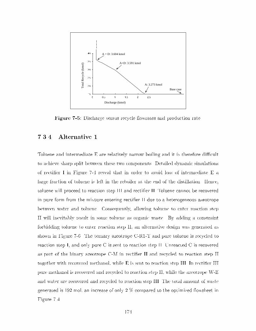
A + D: 3.604 kmol
A+D: 3.591 kmol
A: 3.273 kmol
Discharge (kmol)
Tot
al R
ecyc
le (
kmol
)
Base case
Figure ��� Discharge versus recycle �owrates and production rate�
���� Alternative �
Toluene and intermediate E are relatively narrow boiling and it is therefore di�cult
to achieve sharp split between these two components� Detailed dynamic simulations
of recti�er I in Figure �� reveal that in order to avoid loss of intermediate E a
large fraction of toluene is left in the reboiler at the end of the distillation� Hence�
toluene will proceed to reaction step III and recti�er II� Toluene cannot be recovered
in pure form from the mixture entering recti�er II due to a heterogeneous azeotrope
between water and toluene� Consequently� allowing toluene to enter reaction step
II will inevitably result in some toluene as organic waste� By adding a constraint
forbidding toluene to enter reaction step II� an alternative design was generated as
shown in Figure ��� The ternary azeotrope CR�T and pure toluene is recycled to
reaction step I� and only pure C is sent to reaction step II� Unreacted C is recovered
as part of the binary azeotrope CM in recti�er II and recycled to reaction step II
together with recovered methanol� while E is sent to reaction step III� In recti�er III
pure methanol is recovered and recycled to reaction step II� while the azeotrope WE
and water are recovered and recycled to reaction step III� The total amount of waste
generated is ��� mol� an increase of only � � compared to the optimized �owsheet in
Figure ���
���

Reactor I Rectifier I2R1 + R2
R1 + R2AC
1013 mol C 591 mol R1 5395 mol T 3273 mol A
7723 mol R1 3938 mol R2 106 mol T
SYSTEM BOUNDARY
Reactor IIRectifier II
C + M E
13 mol C 1457 mol M 658 mol E
Reactor IIIRectifier III
2E + W D + 2M
656 mol M18.96 kmol W 116 mol E 328 mol D
658 mol E
328 mol D
Purge: 39 mol C-R1-T 86 mol T Purge: 26 mol W-E
13 mol M 44 mol M 352 mol W
3273 mol A
1931 mol C-R1-T4285 mol T
658 mol C 20 mol C-M1422 mol M
643 mol M
1319 mol W-E17730 mol W
Purge: 28 mol M
Figure ��� Alternative �� no toluene should enter recti�er II�
���� Alternative �
Recovered methanol from reaction step III may possibly contain some water� How
ever� no water should enter reaction step II as this may result in premature reaction
of E to produce D� Hence� if methanol from reaction step III is to be recycled to
reaction step II drying of the stream is necessary� This may not be desirable� and an
alternative design has been generated forbidding such recycle� The resulting �owsheet
is shown in Figure ��� Observe that the �owsheet is identical to the �owsheet in
Figure �� except that recovered methanol is not recycled from recti�er III but dis
posed of as waste� The design emits �� mol of waste� mainly due to the generation
of methanol in reaction step III�
Table ��� summarizes the emission levels� yield� and total amounts recycled for
each process design�
��� Summary
Two realistic case studies are presented to illustrate the design approach introduced
in Chapter �� The mathematical programming formulation is used to generate several
dierent process alternatives by adding design constraints to the formulation� The
���

Reactor I Rectifier I2R1 + R2
R1 + R2AC
665 mol C 590 mol R1 5395 mol T 3273 mol A
7723 mol R1 3938 mol R2 106 mol T
SYSTEM BOUNDARY
Reactor IIRectifier II
C + M E
13 mol C 1457 mol M 658 mol E
Reactor IIIRectifier III
2E + W D + 2M
656 mol M 18.96 kmol W 116 mol E 328 mol D658 mol E
328 mol D
Purge: 26 mol W-E Waste: 656 mol M687 mol M 352 mol W
3273 mol A
1931 mol C-R1-T4285 mol T
658 mol C 20 mol C-M1422 mol M
1319 mol W-E17730 mol W
Purge: 28 mol MPurge: 86 mol T 39 mol C-R1-T
Figure ��� Alternative �� no methanol recycled from recti�er III to reaction stepII�
Table ���� Summary of emission levels� yield� and total amounts recycled �kmol perbatch��
Emissions Yield �A � D� RecycleBase case � ��� �Opt� �owsheet ��� � ����� �����Alternative � ����� ����� �����Alternative � �� �� ����� �����
process alternatives generated show that an intuitive and automated formulation can
produce minimum emission designs very rapidly� It is believed that this decision
support tool will be particularly useful in the early stages of process development en
abling the engineer to automatically generate and explore minimum emission designs
interactively by adding constraints in an evolutionary manner�
Furthermore� it is veri�ed that the formulation can be extended to explore the
space of noninferior solutions corresponding to the tradeos between quantity of
waste emitted and the cost of recovering and recycling solvent� The mathematical
properties of the formulation guarantee this space to be generated e�ciently and
correctly� In fact� it is believed that the primary value of the work will be the ability
���

to generate noninferior solutions in a systematic and automated manner� omitting the
need for an ad hoc and manual generation of �possibly inferior� design alternatives
as currently practiced in industry�
���

��

Chapter
Plant�wide Design of Solvent
Mixtures
In this chapter the mathematical programming formulation presented in Chapter �
is extended to provide a general framework for the design of multiproduct batch
manufacturing facilities in which solvent use is integrated across parallel processes�
The goal is to integrate the reaction steps and separation network of the processes
such that the generation of waste streams that cross the plant boundary is minimized�
Solvent integration across parallel processes may be advantageous if� for exam
ple� the processes have dierent purity requirements� High purity requirements will
typically require a larger purge fraction� It may therefore be bene�cial to recycle
the recovered solvent to a process with lower purity requirements and lower purge
fraction� Thereby the amount of purge will be lower� Improvements from integrating
across processes may also be achieved if an azeotrope formed in one process cannot
be recycled within the process� but can be accepted in another process� For example�
if an azeotrope formed between components where one or more is needed as solvent
in a particular reaction task� while the other component�s� are restricted from en
tering the same reaction task because this may lower the yield� result in undesired
sidereactions� etc� It may instead be acceptable to recycle the azeotrope to another
process if one or more of the components involved are required in the process and the
other component�s� will not result in undesired sideeects� Breaking the azeotrope
���

may also be accomplished by recycling the azeotrope to another process where a
component is present that acts naturally as an entrainer� The recovered solvent can
then be recycled back to the original process� Similarly� a solvent that is used in one
process may be used as an entrainer in another process and therefore sent to the other
process� Depending on the sizes of the entrainer stream and the azeotropic stream
it may be more advantageous to allow the solvent stream rather than the azeotropic
stream to cross the process boundaries� Several of these bene�ts are demonstrated in
the case studies in Chapter ��
The methodology is best suited to processes with parallel campaigns that coincide
or are relatively close in time� Recovery and recycling of solvent in batch manufactur
ing will always require some intermediate storage� Because of the generally hazardous
�in particular� �ammable� nature of the solvents it is desirable to limit quantities and
also the time span required for storage�
Trace contaminants are often a concern in the pharmaceutical industry� In such
situations solvent integration across processes should be used with caution� and prob
ably restricted to recycling between stages for the production of a single product�
��� Problem Statement
The problem that is addressed can be stated as follows�
Given a set of parallel processes each described by a set of reaction tasks
with known stoichiometry and a set of acceptable solvent and entrainer
candidates� synthesize a batch reaction and separation network for each
process that satis�es production demand while integrating solvent recov�
ery and recycling in order to minimize the waste generated�
The same assumptions as those of the processwide design formulation presented
in Chapter � apply�
� The magnitude of the streams entering the separation tasks is assumed to be
proportional to the cost of separating and recycling solvent�
� �

� A separation task is assumed to follow each reaction task� However� the opti
mization may choose to omit the distillation task� and instead let the reaction
task feed directly to the next reaction task
� Only material leaving a separation task can cross the system boundary�
� The process �owrates are computed as time averaged �ows in a batch process
based on overall mole balances�
� Batch distillation is the separation method of choice�
� All streams to be separated are homogeneous�
� Perfect splits can be achieved�
The objective function is a modi�ed version of ����� presented in Chapter ��
minXs�S
Xd�Ds
Xi�I
FDinsdi
s�t� minXs�S
Xd�Ds
Xe� �E
CeFDwsde
� ���
where S represents the set of parallel processes� Ds is the set of separation tasks in
process s� FDinsdi is the �ow of component i into separation task d in process s� I is the
set of pure components� "E represents the set of product cuts �separated compositions�
that will end up as waste if they cross the system boundary� and FDwsde is the amount
of composition e from separation task d in process s crossing the system boundary�
��� Reaction�Separation Superstructure
The overall reactionseparation superstructure is illustrated in Figure � using two
parallel processes� Each separation task is represented by a node for each �xed point�
A �xed point node may take input only from the corresponding separation task�
and output material to the environment� to all separation tasks in all processes� and
to all reaction tasks in all processes as shown in Figures �� and ��� The super
� �

simplex introduced in Chapter � is embedded into the modeling framework and will
correspond to the overall composition simplex of mixtures of all the components that
may appear in all the processes included in the reactionseparation superstructure�
This set of components will include raw material and products� in addition to several
candidate solvents and entrainers�
R1
Reactors
R2
Rj
D1
Columns
D2
Dd
Internal recycle
Process A
System Boundary
Environment
R1
Reactors
R2
Rj
D1
Columns
D2
Dd
Internal recycle
Process B
To other process
Figure �� Reactionseparation superstructure for plantwide design of solvent mixtures involving two processes�
��� Mathematical Formulation
To derive the mathematical formulation� the following index sets will be used to
characterize the topology of the superstructure� The �xed points will be represented
by the index set E � feg� The set of pure components� which is a subset of E�
will be represented by I � fig� S � fsg represents the number of parallel processes�
and Js � fjg represents the number of reaction tasks in process s� The number of
reactions taking place in a particular reaction task is denoted by Rj � fg� Each
of the reaction tasks will be followed by a distillation task� The distillation tasks
in process s are represented by Ds � fdg� In the mathematical formulation each
batch distillation region in the super simplex will be represented by its corresponding
� �

product simplex� NB � fbg denotes the batch distillation regions� Kb � fkg denotes
the individual product cuts� and Kbe denotes the product cuts in batch distillation
region b with composition equal to �xed point e�
The �ows into and out of reaction task j in process s of component i are given
by FRinsji and FRout
sji � Although FRoutsj is a single stream� it is represented by sepa
rate �owrates for each individual pure component� This is done in order to avoid
using molefractions� which would result in nonlinearities in the model� The �ow of
component i from reaction task j to reaction task "j in process s is given by FRout
sj�ji�
and the �ow of component i from reaction task j to distillation task d in process s is
given by FRoutsjdi� The �ow of material with composition equal to �xed point e from
distillation task d in process "s to reaction task j in process s is given by FDR �sdsje�
and the �ow of material equal to �xed point e from the environment to reaction task
j in process s is given by FEoutsje� Flow into batch distillation column d in process
s of component i is represented by FDinsdi� The �ow of distillation cut k in batch
distillation region b from column d in process s is denoted by FDoutsdbk� and the total
amount of material recovered in column d in process s exhibiting the composition of
�xed point e is denoted by FDToutsde� FRout
sjdiis the �ow of component i out of reaction
task jd in process s preceding distillation task d in process s� FEoutsde is the �ow of
material with composition equal to �xed point e from the environment to distillation
task d in process s� and FDD�s�dsde is the �ow of material from distillation task "d in
process "s to distillation task d in process s with composition equal to �xed point e�
Ysdb � f�� �g is a binary variable denoting an active or inactive region� Ysdb � � if the
initial reboiler composition in column d in process s is located in region b� Otherwise�
Ysdb � �� Lsd is a binary variable denoting an active or inactive distillation task�
Lsd � � if material is fed to distillation task d� otherwise Lsd � � if material is fed to
distillation task d in process s� Otherwise� Lsd � �� M is a large scalar� The value of
M is selected carefully such that if Ydb � � or Lsd � �� the values of the �owrates are
not constrained� FEinsde denotes �ow of �xed point e from distillation task d in pro
cess s to the environment� and PURGEsde is the amount of purge with composition
equal to �xed point e from column d in process s� The resulting mixedinteger linear
� �

programming �MILP� problem is�
FRinsji �
X��Rj
�sj��sj�i � FRoutsji �s � S� j � Js� i � I � ���
FRinsji �
Xe�E
SSeFRinsje �
X�j�J
FRout
s�jji �s � S� j � Js� i � I � ���
FRinsje �
X�s�S
Xd�Ds
FDR�sdsje � FEoutsje �s � S� �j � Js� e � E� ���
FRoutsji �
X�j�J
FRout
sj�ji �X�j�J
FRoutsjdi �s � S� j � J� i � I � ���
FDinsdi �
Xb�NB
Xk�Kb
pbkiFDoutsdbk �s � S� d � Ds� i � I � ���
FDinsdi �
Xj�J
FRoutsjdi �
Xe�E
SSie�FEoutsde �
X�s�S
X�d�D
FDD�s �dsde� �s � S� d � Ds� i � I � ���
FDTsde �X
b�NB
Xk�Kbe
FDoutsdbk �s � S� d � Ds� e � E � � �
Xk�Kb
FDoutsdbk � MYsdb �s � S� d � Ds� b � NB � ���
Xb�NB
Ysdb � � �s � S� d � Ds � ����
Xi�I
FDinsdi � MLsd �s � S� d � D � ����
FDTsde �Xj�Js
FDRsdje �X�d�Ds
FDDsd �de � FEin
sde �
PURGEsde �s � S� d � Ds� e � E � ����
where �sj�i is the stoichiometric coe�cient for component i in reaction in reaction
task j in process s� The extent of reaction �sj� is the same for all species taking part
in reaction � The element SSie is the molefraction of component i in �xed point e�
pbki is the mole fraction of pure component i in product cut k from batch distillation
region b� Also note that FRout
sj�jimust be set to zero for all reaction tasks "j that are
not directly downstream to reaction task j �both tasks j and "j are in process s�� and
FRoutsjdi � � for all distillation tasks d that are not directly downstream to reaction
task j in process s� Likewise� FRout
s�jji� � for all reaction tasks "j that are not directly
preceding reaction task j�
� �

The purge streams are computed using Equations � ���� and � ����� It is assumed
that all streams that are integrated across processes are purged�
PURGEsd�se��� �sd�se� �
�BBBBB�
Xj�Jsdu
�s
FDRsd�sje�
X�d�Dsdu
�s
FDDsd�s �de
�CCCCCA �s � S� d � D� e � E � ����
PURGEsde �X�s�S
PURGEsd�se �s � S� d � Ds e � E � ����
where Jsdu�s represents the set of reaction tasks in process "s that are upstream of
distillation task d in process s� and Dsdu�s represents the set of distillation tasks in
process "s that are upstream of distillation task d in process s� Note that Jsdu�s includes
all reaction tasks in processes other than s in addition to the ones that are upstream
in process s� Dsdu�s includes all distillation tasks in processes other than s in addition
to the ones that are upstream in process s and the distillation task d itself� �sd�se is
the purge fraction of streams with composition equal to �xed point e from column d
in process s to process "s� PURGEsd�se denotes the purge of streams with composition
e from column d in process s to process "s� and PURGEsde denotes the overall amount
of purge with composition e from column d in process s�
The choice of purge fraction will depend on the purity requirements in the partic
ular problem of interest� A process with high purity requirements will require larger
purge fractions on recycled streams than a process with lower purity requirements�
For processes with similar purity requirements the same purge fraction can be used
on all recycled streams� However� in order to make the optimization favor internal
recycle to recycle across process boundaries a slightly lower purge fraction should
be chosen on internal recycle streams compared to streams that are recycled across
processes�
��� Summary
A mixedinteger linear programming formulation for the design of multiproduct man
ufacturing facilities in which solvent use is integrated across parallel processes is pre
� �

sented� The formulation is an extension to the formulation for design of single batch
processes presented in Chapter �� A novel reactionseparation superstructure that
yields a modeling framework for the plantwide design of the mixtures formed in a
batch process is introduced� The super simplex presented in Chapter � is embedded
into the modeling framework and will correspond to the overall composition simplex
of mixtures of all the components that may appear in all the processes included in
the reactionseparation superstructure�
Solvent integration across parallel processes may be advantageous if the processes
have dierent purity requirements� and thereby dierent requirements on purging�
It may be acceptable to run a reaction step in an azeotropic composition recovered
in a parallel process rather than in the pure solvent as speci�ed by the chemist� A
naturally present entrainer may be exploited by recycling an azeotropic composition
to a parallel process� The recovered solvent can then be recycled back to the original
process� Several of these bene�ts are demonstrated in two case studies in Chapter ��
� �

Chapter �
Case Studies on Plant�wide Design
of Solvent Mixtures
This chapter presents results from two case studies where the formulation for plant
wide design of solvent mixtures was applied� The �rst case study involves the manu
facture of benzonitrile intermediates and shows that integrating solvent usage across
parallel processes is bene�cial when the processes have dierent purity requirements�
The second case study demonstrates the advantages of plantwide integration of sol
vent usage when a recovered azeotrope cannot be recycled internal to the process� The
case study also demonstrates how a solvent can act as a naturally present entrainer
to break an azeotrope recovered in a parallel process�
��� Case Study �
The �rst case study involves the production of two substituted benzonitrile com
pounds �Ar� and Ar��� These compounds are used as intermediates to dyes and
other specialty chemicals� Figure �� shows the base case� Ar� is processed through
three synthetic steps �process ��� a Sandmeyer reaction� Nitration� and B%echamp re
duction� respectively� from R� via intermediates I�� and I��� Ar� is processed through
two synthetic tasks �process ��� a Sandmeyer reaction and B%echamp reduction� re
spectively� from R� via intermediate I��� More details about the synthetic steps can
� �

be found in Knight and McRae ������ and Knight ������� Five dierent solvents are
used in the two processes �Clarke and Read� ����� Groggins� ��� � Streitwieser et al��
������ In the base case toluene is used in reaction steps ��� and ���� However� either
benzene or toluene may be used for the Sandmeyer reaction� For reaction steps ���
and ��� a ����� mixture of methanol and ethanol on a mole basis is used� but both
methanol and ethanol are acceptable alone� Water is consumed in some steps and
formed in others� In the base case aqueous waste is separated from the organic phase
in a decanter after both reaction tasks ��� and ���� It is assumed that the intermedi
ate remains in the organic phase �primarily toluene�� Acetic acid may not enter any
other reaction tasks than ���� and the intermediate I�� is therefore recovered through
crystallization after reaction step ���� Likewise� Ar� and Ar� are crystallized out and
recovered after reaction tasks ��� and ���� respectively� The stream compositions for
the base case can be found in Appendix F�
����� Separation Sequences
It is assumed that the key reagents react to complete conversion� and that the in
termediates can be recovered through either crystallization or a liquidliquid phase
split after each synthetic step� Hence� only the solvents that are used will enter
the batch distillation columns� Six solvents therefore form the super simplex� wa
ter �W�� methanol �M�� ethanol �E�� benzene �B�� toluene �T�� and acetic acid �A��
The azeotropic behavior was approximated using the UNIQUAC �Universal Quasi
Chemical Theory� �Abrams and Prausnitz� ����� model to calculate the activity
coe�cients� The binary interaction parameters were extracted from Aspen Plus �As
pen Technology� ������ Missing parameters were estimated using the UNIFAC group
contribution method �Fredenslund et al�� ����� implemented in Aspen Plus �Aspen
Technology� ������ The vapor phase was assumed to be ideal� The components form
eight binary azeotropes and two ternary azeotropes� The �xed points are listed in
Table ����
When applying the algorithm described in Chapter � twentyseven separation
sequences were found� However� benzene and toluene form heterogeneous mixtures
�

Reactor 1.1 Reactor 1.2 Reactor 1.3
1
23
45
6
7
8
9
1011
12
13
toluenewater acetic acid
aq. waste
R1
watertolueneacetic acid
methanolethanolwater
Ar1
methanolethanolwater
R1 I11 + 2W I12 + W Ar1I11 I12 + W
PROCESS 1
Reactor 2.1 Reactor 2.2
1
23
45
6
7
8
9
toluenewater
aq. waste
R2
methanolethanolwater
methanolethanoltoluenewater
Ar2
PROCESS 2
R2 I21 + 2W I21 + W Ar2
Figure ��� Base case with solvent requirements�
with water� The composition simplex involving all six components therefore will
have domains which are heterogeneous� The algorithm for constructing the super
simplex assumes that the mixtures to be separated are homogeneous� Hence� some
of the distillation sequences that were found may not be feasible� In order to ensure
feasible separation� we constrain the problem so that water may never mix with
benzene and toluene in any of the columns� Note that this amounts to introducing
two super simplices� which is what was also done in the case study in Chapter �� The
optimization will be constrained to operate only on the face involving all components
except water� or on the face involving water but not toluene and benzene� Each
sequence will produce six product cuts as shown in Table ���� The binary azeotrope
� �

Table ���� Compositions� boiling temperatures� and stability of �xed points at �atmosphere� un indicates unstable node� s indicates saddle point� and sn indicatesstable node� � indicates that the azeotrope is heterogeneous�
e M E B W T A TB�K� typeMB ���� � ���� � � � ����� unMT ��� � � � ��� � ���� sM � � � � � � ����� sEBW � ���� ���� ��� � � ����� s�EB � ���� ���� � � � ����� sBW � � ��� ��� � � ����� s�EWT � ���� � ��� ���� � ���� s�ET � �� � � � ���� � ��� sEW � ��� � ��� � � ����� sE � � � � � � ����� sB � � � � � � ����� sWT � � � ���� ���� � ����� s�W � � � � � � ����� sTA � � � � ���� ��� � ��� sT � � � � � � � � snA � � � � � � ����� sn
between methanol and benzene �MB� is the only unstable node and therefore all
product sequences will start with the methanolbenzene azeotrope as the �rst product
cut�
����� Analysis of Base Case
For the base case it is assumed that there is no internal recovery and recycling of
solvents� Instead the mixed wastesolvent streams �streams and �� in process ��
and stream in process �� are collected and sent to a central wastetreatment facility�
The mixture to be treated contains both toluene and water and is therefore hetero
geneous� The mixture is �rst separated into an organic phase and an aqueous phase
�see Table ����� and the organic layer is sent to a batch distillation column� The
liquidliquid phase split was simulated using Aspen Plus �Aspen Technology� �����
with UNIQUAC �Abrams and Prausnitz� ����� to approximate the nonideal liquid
behavior�
���

Table ���� Separation sequences in the composition simplex�
b Product sequences b Product sequences� fMB� MT� M� EW� W� Ag �� fMB� EWB� BW� B� TA� Tg� fMB� MT� M� EW� E� Ag �� fMB� EWB� BW� B� TA� Ag� fMB� MT� EWT� ET� E� Ag �� fMB� EWB� BW� WT� TA� Tg� fMB� MT� EWT� ET� TA� Tg � fMB� EWB� BW� WT� TA� Ag� fMB� MT� EWT� ET� TA� Ag �� fMB� EWB� EWT� ET� E� Ag� fMB� MT� EWT� WT� TA� Tg �� fMB� EWB� EWT� ET� TA� Tg� fMB� MT� EWT� WT� TA� Ag �� fMB� EWB� EWT� ET� TA� Ag fMB� MT� EWT� EW� E� Ag �� fMB� EWB� EWT� EW� E� Ag� fMB� MT� EWT� EW� H� Ag �� fMB� EWB� EWT� EW� W� Ag�� fMB� EWB� EB� B� TA� Tg �� fMB� EWB� EWT� WT� TA� Tg�� fMB� EWB� EB� B� TA� Ag �� fMB� EWB� EWT� WT� TA� Ag�� fMB� EWB� EB� ET� E� Ag �� fMB� EWB� WB� WT� W� Ag�� fMB� EWB� EB� ET� TA� Tg �� fMB� MT� EWT� WT� W� Ag�� fMB� EWB� EB� ET� TA� Ag
Table ���� Composition of mixed wastesolvent stream in base case to central treatment facility �kmol per batch��
Component Waste stream Organic layer Aqueous layerToluene ����� ����� ����Acetic Acid ����� ���� �����Methanol ��� � ���� �� �Ethanol ��� � ���� ����Water ���� ���� ��� �Total � ��� ���� �����
It was assumed that the organics in the aqueous layer would end up as waste
�about ���� kmol�� Solvent recovery targeting was applied to the stream composition
of the organic layer �the small amount of water was ignored�� The stream was placed
on the boundary of batch distillation region � giving rise to the sequence fMT� ET�
TA� Tg� It was found that about ��� of organic waste would be generated from this
stream assuming no use of entrainers� For example� the distillation would produce the
binary azeotrope methanoltoluene� Since toluene can only be fed to reaction tasks
��� and ���� and it is not desirable to introduce methanol in these reaction tasks�
���

the azeotrope must be disposed of� Also� the binary azeotrope tolueneacetic acid is
generated and cannot be recycled� Hence� a total of �� kmol of organic waste per
batch would be generated from the base case�
����� Formulation of Optimization Problem
The mathematical synthesis formulation presented in Chapter was applied to the
two processes� In addition to the constraints discussed above� a set of design re
quirements was speci�ed� Lower bounds on solvent requirements speci�ed in terms
of moles were introduced�
� The amount of water in reaction task ��� has to be greater or equal to �� times
the amount of R��
� The total amount of benzene and toluene in reaction task ��� has to be greater
or equal to three times the amount of R��
� The amount of acetic acid in reaction task ��� has to be greater or equal to ���
times the amount of I���
� The amount of water in reaction task ��� has to be greater or equal to � times
the amount of I���
� The total amount of methanol and ethanol in reaction task ��� has to be greater
or equal to ���� times the amount of I���
� The amount of water in reaction task ��� has to be greater or equal to �� times
the amount of R��
� The total amount of benzene and toluene in reaction task ��� has to be greater
or equal to � times the amount of R��
� The amount of water in reaction task ��� has to be greater or equal to � times
the amount of I���
���

� The total amount of methanol and ethanol in reaction task ��� has to be greater
or equal to ���� times the amount of I���
No water can be added to reaction task ��� as this would lower the yield� and
acetic acid may not enter any other reaction task than ���� The purity requirements
are higher for product Ar� than for product Ar�� A purge fraction of ����� was used
for recycled streams internal to process �� and ���� was used for recycled streams
from process � to process �� A purge fraction of ����� was speci�ed for recycled
streams internal to process �� and ���� was used for recycled streams from process
� to process �� The incremental higher purge fractions for streams integrated across
processes were chosen to favor internal recycling if possible� A weighting factor of �
was used for all waste� The feed of R� was set to ����� kmol producing about ���
kg of Ar�� and the feed of R� was set to ����� kmol producing about ��� kg of Ar��
The problem was formulated in GAMS �Brooke et al�� ����� as an MILP with ����
equations and ��� binary variables� and solved on an HP �������� workstation by
OSL �IBM Corporation� ����� in ����s�
����� Results
The optimized �owsheet with the integrated solvent streams is shown in Figure ���
Toluene is recovered through �ltration after the aqueous phase split and is recycled
internally to the �rst reaction task in both processes� In addition� toluene is recycled
from process � to process � to make up for lost toluene through purging� Makeup
for toluene and methanol is only introduced in process �� It is advantageous to use
as much fresh material as possible for the process with the higher purity require
ment� in this case process �� and it reduces the overall loss due to dierent purge
fractions� Similarly� methanol is recovered through batch distillation after the last
reaction task and recycled internally in both processes� In addition methanol is re
cycled from process � to process � to make up for lost methanol through purging�
Acetic acid is recovered and recycled internally in process �� while water is recovered
in process � and recycled to process �� The amount of organic waste generated is
���

���� mol resulting only from the purge streams as indicated in the �gure� About
����� kmol of aqueous waste is also emitted� No azeotropic mixtures are produced�
Hence� optimization in the super simplex has driven the mixtures formed in the pro
cess to lower dimensional faces� thus avoiding systems with azeotropic compositions�
Also observe that methanol was chosen as the solvent for reaction tasks ��� and ����
Ethanol forms a binary azeotrope with water� and the use of ethanol would therefore
generate additional waste� Toluene was chosen as solvent for reaction tasks ��� and
���� However� use of benzene instead would not change the value of the objective
function� Introducing dierent weighting factors to re�ect dierences in toxicity or
treatment cost would help to discriminate components in such cases�
For comparison� forbidding the processes to integrate� but allowing recycling in
ternal to each process would result in process designs that would generate about
������ mol of organic waste �see Figures �� and ���� Hence� integrating solvent use
across parallel processes has lead to a ��� reduction in the amount of organic waste
generated compared to recycling only internal to each process� Compared to the use
of a central recovery facility as in the base case an overall reduction in organic waste
of about ��� has been achieved� Stream tables for the �owsheets in Figures ��� ���
and �� can be found in Appendix F�
��� Case Study �
This case study involves two parallel processes� each with two reaction steps� The
chemistry and solvent requirements are indicated in Figure ��� Four dierent solvents
are used in the two processes� Methanol �M� is used in reaction task ���� and toluene
�T� is used in reaction task ���� Methanol is one of the products in reaction task
���� Reaction task ��� requires isopropanol �IP�� while reaction task ��� requires a
mixture of ethylacetate �EA� and methanol�
����� Separation Sequences
The compounds involved in the reactions �except methanol� do not form azeotropes
with any of the solvents� Furthermore� they are heavy boiling and can be taken out
���

aq. waste
Reactor 1.1 Reactor 1.2 Reactor 1.3
1R1Ar1
R1 I11 + 2W I12 + W Ar1I11 I12 + W
PROCESS 1
Reactor 2.1 Reactor 2.2
aq. waste
R2 + WAr2
PROCESS 2
R2 I21 + 2W I21 + W Ar2
5
6
7
8
4 (T)2 (T+W)
17 (T)
9 (T)
11 (A)
10 (A)
12 (A)
14 (M)
13 15 (M) 16 (W)
18 (W)
19
20
22
23
25 (M)
24 (W)
26 (T) 29 (W)
(M+W)
21 (T)
27(W)
3
28 (M)
30 (M)
Figure ��� Case study �� integrated �owsheet�
as bottom products in the distillation tasks� Hence� only the solvents are included in
the super simplex� The azeotropic behavior was approximated using the UNIQUAC
�Universal QuasiChemical Theory� �Abrams and Prausnitz� ����� model to calcu
late the activity coe�cients� The binary interaction parameters were extracted from
Aspen Plus �Aspen Technology� ������ Missing binary interaction parameters were
estimated using the UNIFAC group contribution method �Fredenslund et al�� �����
implemented in Aspen Plus �Aspen Technology� ������ The vapor phase was assumed
to be ideal� The components form three binary azeotropes �see Table �����
When applying the algorithm described in Chapter � four separation sequences
���

aq. waste
Reactor 1.1 Reactor 1.2 Reactor 1.3
1R1Ar1
R1 I11 + 2W I12 + W Ar1I11 I12 + W
PROCESS 1
3
5
6
7 84 (T)
17 (A) 15 (M)
9 (W)
10 (T) 11 (A) 12 (A) 13 (M+W) 14 (M)16 (W)
2 (W+T)
Figure ��� Case study �� process � with no integration�
Reactor 2.1 Reactor 2.2
1
aq. waste
R2Ar2
PROCESS 2
R2 I21 + 2W I21 + W Ar2
2 (T+W)
3
5
6
13 (M)
7 (W)
9 (M+W)8 (T)10 (M)
11 (W)
4
Figure ��� Case study �� process � with no integration�
were found� Each sequence will produce four product cuts as shown in Table ���� The
binary azeotrope between methanol and ethylacetate �MEA� is the only unstable
node and therefore all product sequences will start with this azeotrope as the �rst
product cut�
���

Reactor 1.1
A
A B
methanol
Reactor 1.2
B C + methanol
toluene
B
PROCESS 1
Reactor 2.1
D + E
D + E F
iso-propanol
Reactor 2.2
F G
methanol +ethyl acetate
F
PROCESS 2
Figure ��� Case study �� solvent requirements�
Table ���� Compositions� boiling temperatures� and stability of �xed points at �atmosphere� un indicates unstable node� s indicates saddle point� and sn indicatesstable node�
e M EA IP T TB�K� typeMEA ��� ��� � � ����� unMT ��� � � ��� ���� sM � � � � ����� sEAIP � ���� ���� � �� �� sEA � � � � ����� sIP � � � � ����� sT � � � � � � sn
����� Formulation of Optimization Problem
The mathematical synthesis formulation presented in Chapter was applied to the
two processes� In addition to the constraints discussed above� a set of design require
ments was speci�ed� Lower bounds on solvent requirements speci�ed in terms of mol
were introduced�
���

Table ���� Separation sequences in the composition simplex�
b Product sequences� fMEA� MT� M� IPg� fMEA� MT� IPA� Tg� fMEA� EAIP� EA� Tg� fMEA� EAIP� IP� Tg
� The ratio of methanol to reagent A for reaction task ��� should be greater or
equal to ��
� The ratio of toluene to intermediate B for reaction task ��� should be greater
or equal to ����
� The ratio of isopropanol to reagent D in reaction task ��� should be greater or
equal to ��
� The ratio of methanol to intermediate F in reaction task ��� should be greater
or equal to ��
� The ratio of ethylacetate to intermediate F in reaction task ��� should be
greater or equal to ����
Toluene should not enter reaction task ��� as this would result in undesired side
reactions� Methanol should not be fed to reaction task ���� Methanol is generated in
this reaction task and methanol in the feed will prevent complete conversion� A purge
fraction of ����� was speci�ed for streams being recycled internal to each process� and
a purge fraction of ���� was used on streams recycled across process boundaries� The
incremental higher purge fractions for streams integrated across processes were chosen
to favor internal recycling if possible� The weighting factors were initially set to � for
all waste streams� A basis of ���� mol of A was used in process �� and a basis of ����
mol of D was used in process �� The problem was formulated in GAMS �Brooke et
al�� ����� with ��� equations and �� binary variables and solved on an HP ��������
workstation by OSL �IBM Corporation� ����� in ����s�
��

����� Results
Two scenarios were proposed�
�� No integration between processes�
�� Integration between processes�
Permitting no integration between processes will result in approximately ���� mol of
waste emitted� while scenario � will result in �� � mol of emissions� Hence� we have
achieved an improvement of � � compared to only allowing recycling within the in
dividual processes� Figures �� an �� show the �owsheets resulting from not allowing
integration between the processes� The stream data can be found in Appendix G�
Reactor 1.1
1 (A)
A B
Reactor 1.2
B C + methanol
3 (M)
5 (M) 9 (T)
7 (T)
10 (T)
4 6
C
8 (MT)
PROCESS 1
2 (M)
Figure ��� Case study �� process � with no integration�
Figure � shows the optimized �owsheet for scenario �� Methanol and toluene
form a unavoidable binary azeotrope since methanol is generated in reaction task ���
while toluene is used as a solvent in the same task� Since toluene cannot be recycled
back to reaction task ��� where methanol is used as a solvent� the methanoltoluene
azeotrope must either be disposed of or recycled to process �� In the integrated �ow
sheet a combination takes place� some of the azeotrope is recycled to distillation task
���� where the azeotrope is eectively broken by the presence of ethyl acetate� and
toluene is recovered in pure form and recycled back to reaction task ���� The binary
azeotrope methanolethyl acetate is also recovered� but can be recycled to reaction
���

Reactor 2.1
D + E F F G
6 (IP)
5 (IP)
2 (IP)
7 (M + EA) 8 (MEA + EA)
3 41 (D + E)
G
9 (MEA + EA)
Reactor 2.2
PROCESS 2
Figure ��� Case study �� process � with no integration�
task ��� where both components are required as solvents� The binary azeotrope is also
recycled to reaction task ��� where methanol is used as solvent� Hence� the synthesis
in reaction task ��� takes place in the methanolethyl acetate azeotrope� Since there
is a net generation of methanol� some methanol has to be disposed of� This is accom
plished through the emission of the remaining of the methanoltoluene azeotrope� and
the methanolethyl acetate purges� Furthermore� note that no methanol makeup is
required� The losses of methanol and ethyl acetate in process � are replaced through
stream � from process �� Stream tables for the integrated �owsheets can be found in
Appendix G�
The breaking of the methanoltoluene azeotrope is illustrated in Figure ��� The
mixture that enters distillation task ��� is composed of methanol� ethyl acetate� and
toluene� The methanoltoluene azeotrope is recycled from process �� while a mixture
of the methanolethyl acetate azeotrope and ethyl acetate makeup �labeled xa in
Figure ��� is fed from reaction task ���� The makeup of ethyl acetate is exactly
balanced to place the mixture on the straight line between the methanolethyl acetate
azeotrope and pure toluene �labeled xb in Figure ���� resulting in recovery of pure
toluene� Also note that the vertex for pure ethyl acetate� and the composition points
xa and xb must lie on a straight line to satisfy the overall material balance�
���

Reactor 2.1
D + E F
Reactor 2.2
F G
PROCESS 2
Reactor 1.1
1 (A)
A B
Reactor 1.2
B C + methanol
PROCESS 1
2 (MEA)
6 (MEA)
9 (MEA)20 (IP)
19 (IP)
18 (IP)
7 (T)
4 (T)
17 (EA) 16(MEA)
21(MEA)
8 (T)12(MT)
11 (MT)
14 1513 (D + E)
10 (T)
3 5
22 (T)
C
G
Figure �� Optimized �owsheet for integration of recovered solvent across processboundaries�
����� Alternative Flowsheets
In the above formulation the weighting factors for all the dierent waste compositions
were set to �� However� dierent weighting factors can be introduced to discriminate
between dierent compositions or components� In order to re�ect the dierence in
toxicity of toluene compared to the other components it was decided to increase the
weighting factors of discharge of pure toluene as well as of the methanoltoluene
azeotrope� Table ��� shows the weighting factors that were used� The values in case
� is the same as for the �owsheet in Figure � � The weighting factors in case �
was found by assuming that toluene is ��� times as toxic as the other components�
���

Toluene384 K
Ethyl acetate 350.3 K
Methanol337.8 K
335.3 K
336.8 K xa: mixture ofmethanol-toluene azeotrope andmethanol-ethyl acetate azeotrope
xb: mixture of pure toluene andmethanol-ethyl acetate azeotrope
Figure ��� Ethyl acetate acts as an entrainer to break the methanoltolueneazeotrope�
The weighting factor for the methanoltoluene azeotrope was found by multiplying
the fraction of methanol by � and adding ��� times the fraction of toluene� In case
� it was assumed that toluene is ��� times as toxic as the other components� The
weighting factor for the methanoltoluene azeotrope was found by multiplying the
fraction of methanol by � and adding ��� times the fraction of toluene�
Table ���� Weighting factors�
MEA MT M EAIP EA IP TCase � � � � � � � �Case � � ���� � � � � ���Case � � ��� � � � � ���
It is expected that an increase in the weighting factor of toluene will discourage
discharge of toluene and instead favor increased recovery and recycling� Figure ���
re�ects the results of these calculations� Note that the amount of methanol that is
discharged remains constant and equal to ���� mol� which is the amount of methanol
generated in reaction task ���� Also� the amount of isopropanol emitted remains
constant� The recovery and recycling of isopropanol is isolated from the rest of the
�owsheet and is not eected by the change in weighting factors�
Figure ��� reveals that there is only a slight decrease in the discharge of toluene
���

0
200
400
600
800
1000
1200
1400
1600
1800
Case 1 Case 2 Case 3
ethyl acetate
iso-propanol
toluene
Increasing weighting factor for toluene
Dis
char
ge (
mol
es)
Figure ���� Distribution of discharge when weighting factor of toluene is varied�
in case �� Likewise� there is only a slight increase in the discharge of ethyl acetate�
In contrast� a dramatic change is observed when the weighting factor of toluene is
increased from ��� to ���� The integrated �owsheet for case � is shown in Figure
��� with the stream data in Appendix G� The excess methanol that is generated in
process � and which in the �owsheet in Figure � is emitted through the methanol
toluene azeotrope� is now emitted through the methanolethyl acetate azeotrope from
distillation task � in process �� The generated methanol necessarily has to leave the
system� Methanol can only be recovered as a pure component from batch distillation
region � �see Table ����� However� the design constraints placed on the processes
do not allow a mixture to be placed in that region� For example� with the amount
of toluene required in reaction step ��� the composition out will always be located
in batch distillation regions �� �� or �� Methanol therefore has to escape the system
through an azeotrope �either methanoltoluene or methanolethyl acetate� resulting in
additional losses due to the fraction of the other component involved in the azeotrope�
The methanoltoluene azeotrope is initially favored because the fraction of toluene
�about ���� is relatively small compared to methanol� However� as the weighting
factor is increased it becomes less favorable to emit the methanoltoluene azeotrope�
���

until the fraction of toluene times the weighting factor equals the fraction of ethyl ac
etate in the methanolethyl acetate azeotrope� In this case when the weighting factor
is about �� If the weighting factor is increased further the optimization chooses to
emit the methanolethyl acetate azeotrope instead of the methanoltoluene azeotrope�
Reactor 2.1
D + E F
Reactor 2.2
F G
PROCESS 2
Reactor 1.1
1 (A)
A B
Reactor 1.2
B C + methanol
PROCESS 1
2 (MEA)
6 (MEA)
15 (IP)
14 (IP)
12 (IP)
7 (T)
8 (T)
18 (MEA)
19 (MEA)
9 (T)10(MT)
16 (MEA)
13 1711 (D + E)
3
C
G
4 (B + T)
5 (EA)
Figure ���� Alternative �owsheet�
��� Summary
The results from two case studies where the mathematical synthesis formulation for
plantwide design of solvent mixtures was applied are presented� In both case studies
���

improvements in the range of ����� compared to not allowing integrated recycling
of recovered solvent between parallel processes were achieved�
In the �rst case study the main improvement was due to dierences in purity
requirements in the two parallel processes� which was re�ected in dierent purge frac
tions� As a result it became advantageous to recycle material from the process with
the higher purity requirements and hence higher purge fraction to the process with
lower purity requirements and hence lower purge fraction� and introducing as much
fresh material through makeup streams to the process with high purity requirements�
The second case study achieved the greatest improvements of about ��� compared
to not integrating the two processes� Methanol was a byproduct in process �� but
could not be recovered in pure form� Hence� the excess methanol could only escape
the system through an azeotrope� With no integration this caused additional losses
due to the fraction of the other component involved in the azeotrope� However� when
integration was permitted some of the azeotrope could be recycled to the parallel
process� where a solvent acted as a natural entrainer to break the azeotrope� In the
second case study it was also demonstrated how the use of dierent weighting factors
could be used to discriminate between components to� for example� re�ect dierences
in toxicity or treatment cost� and that this can have a major impact on the process
structures chosen by the optimization�
���

���

Chapter ��
Conclusions and Recommendations
���� Conclusions
One of the many environmental challenges faced by the synthetic pharmaceutical
and specialty chemical industries is the widespread use of organic solvents� Clean
ing solvents are relatively easy to change or eliminate� However� solvents in process
reactions are much more di�cult to substitute� With a solventbased chemistry� the
solvent necessarily has to be separated from the product stream� Although intermedi
ate storage may be required before the solvent can be recycled to subsequent batches�
this should be preferred to disposal of the solvent as toxic waste� This issue provides
the motivation for this work� which focuses on the development of analysis and de
sign tools to address the pollution prevention challenges posed by the use of organic
solvents in the pharmaceutical and specialty chemical industries� In particular� the
eective recovery and recycling of solvents is a primary concern�
So far� research activities have been successful only to a limited extent in address
ing the problems of waste generation in chemical processes� It is our opinion that
much of this de�ciency has arisen from a failure to recognize that the environmen
tal problems faced by the chemical industries require new approaches� as opposed to
adapting current design technologies� The real opportunities lie in how the environ
mental debate should change the way design is performed� rather than vice versa� This
thesis serves as a modest example of how this approach can yield concrete technical
���

solutions leading to signi�cant environmental bene�ts�
Chemical species in wastesolvent streams generated by the pharmaceutical and
specialty chemical industries typically form multicomponent azeotropic mixtures�
This highly nonideal behavior often complicates separation and hence recovery of the
solvents� Our approach is based on understanding and mitigating such obstacles� A
prototype technology is proposed which combines rigorous dynamic simulation mod
els and�or plant data to predict the compositions and magnitude of wastesolvent
streams with residue curve maps to target for the maximum feasible recovery when
using batch distillation�
As such� a complete theoretical understanding of residue curve maps applied to
batch distillation of homogeneous multicomponent mixtures is required� It is demon
strated that earlier work on ternary residue curve maps for batch distillation is not
complete� The theory is further generalized to homogeneous systems with an arbitrary
number of components� The concepts of unstable and stable manifolds� and unsta
ble and stable boundary limit sets are introduced to characterize simple distillation�
Moreover� based on the limiting assumptions of very high re�ux ratio� large number
of trays� linear pot composition boundaries� and a recti�er con�guration� properties
of the batch distillation composition simplex are introduced� It is demonstrated that
the pot composition orbit will be constrained by pot composition barriers present
in the composition simplex� and that a pot composition barrier can be divided into
one or more pot composition boundaries� An initial composition located interior to
a batch distillation region will give rise to exactly nc product cuts� and these nc cuts
form an nc product simplex� It is also found that a batch distillation region and its
corresponding product simplex do not necessarily coincide�
An algorithm for elucidating the structure of the batch distillation composition
simplex for a multicomponent system is described� Identi�cation of the batch distilla
tion regions is accomplished through completion of the unstable boundary limit sets�
The completed boundary limit sets accurately represent the topological structure of
the composition simplex� and also makes it possible to extract all product sequences
achievable when applying batch distillation� The algorithm only requires information
��

of the compositions� boiling temperatures� and stability of the �xed points� and is
guaranteed to �nd the correct unstable boundary limit sets for all �xed points in
the system provided that the system itself and all its subsystems have at most two
unstable and at most two stable nodes� The topological structures included in the
algorithm are categorized by the number of unstable and stable nodes� and whether
the system exhibits an azeotrope involving all components�
The algorithm for identifying the batch distillation regions has been exploited in
a sequential design procedure where process streams or mixed wastesolvent streams
are analyzed for maximum feasible solvent recovery� The procedure is termed solvent
recovery targeting� For a given base case� solvent recovery targeting will� given the
composition of the mixture�s� to be separated� predict the correct distillation sequence
and calculate maximum feasible recovery of each product cut in the sequence� It can
further provide information about all other feasible distillation sequences involving
the same set of pure components� The information is used to evaluate the feasibility
of enhancing solvent recovery in the proposed �owsheet� and to guide in improving
the �owsheet�
A mixedinteger linear programming �MILP� formulation for the automated design
of batch processes with integrated solvent recovery and recycling is also presented�
A super simplex is introduced� which corresponds to the overall composition sim
plex for mixtures of several candidate solvents and entrainers� and in general will
contain multiple azeotropic compositions� It is demonstrated that� under reasonable
assumptions� the feasible sequences of pure component and azeotropic cuts that can
be separated from mixtures in the super simplex can be formulated as linear con
straints in terms of a mixed set of real and binary variables� This result is especially
signi�cant since it facilitates a compact and e�cient mathematical abstraction of the
complex azeotropic behavior that drives the decision process�
The super simplex is embedded in a novel reactionseparation superstructure to
yield a modeling framework for the processwide design of the mixtures formed in
a batch process �primarily design of the mixtures leaving the reaction tasks�� The
modeling framework is �exible� new constraints can be easily added to produce more
���

realistic alternatives� and leads to a compact MILP that can be solved e�ciently
to guaranteed optimality� The methodology can be employed to generate various
designs by adding or removing design constraints in an evolutionary manner� thereby
furnishing the engineer with a set of dierent process designs that can be evaluated
based on other criteria not embedded in the mathematical program� such as reaction
rates �which are functions of selected solvent�� production times� safety� etc�
The mathematical programming formulation for the design of a single batch pro
cess is extended to the design of multiproduct manufacturing facilities in which
solvent use is integrated across parallel processes�
In conclusion� the tangible product of this research work is a set of synthesis tools
that can be employed to guide process modi�cations leading to signi�cantly lower
emission levels through integrated recovery and recycling of solvent as part of the
process �owsheet� The application of the synthesis tools is successfully demonstrated
in several case studies�
���� Recommendations for Future Research
The theoretical results on residue curve maps applied to batch distillation derived in
Chapters � and � form the basis for the synthesis tools developed in this research�
As such� the assumptions imposed on the theoretical derivations will also restrict the
applicability of the synthesis tools� The signi�cance of the limiting assumptions of
very high re�ux ratio� large number of theoretical stages� and linear pot composition
boundaries are touched upon in Section ���� It is concluded that only slight deviation
from the predicted behavior may be observed if any of these assumptions are relaxed�
However� the assumption that the liquid phase remains homogeneous throughout the
distillation has much more fundamental implications� The assumption is not restric
tive when analyzing a single homogeneous stream as in solvent recovery targeting�
However� it dramatically limits the problems that can be investigated with the math
ematical programming formulation for processwide �as well as plantwide� design of
mixtures� The super simplex embeds a range of solvents and entrainers� and it is
���

almost certain that some of these components will form partially miscible pairs� For
example� water is often used in some part of a �owsheet� and will typically form a
partially miscible pair with one or more of the other components in the �owsheet�
In the �rst case study in Chapter � water is almost completely immiscible with both
benzene and toluene� A constraint forbidding water to mix with either benzene or
toluene is therefore included in the mathematical program� which in practice means
that the optimal solution is restricted to lie on one of the facets of the super sim
plex� Hence� the constraint will greatly limit the alternative designs that can be
considered� In the worst case� we may fail to �nd the most environmentally favor
able design� Extending the theory of multicomponent azeotropic batch distillation
to mixtures containing partially miscible pairs is therefore critical in order to allow
solvent recovery targeting as well as the mathematical programming formulation to
be applied to a broader class of manufacturing processes�
The algorithm for identifying batch distillation regions only applies to systems
were the system itself and all its subsystems exhibit at most two unstable and at
most two stable nodes �or globally determined systems�� This assumption is not
very restrictive since systems that do not satisfy this requirement are rarely encoun
tered� In fact� we are not aware of a physical mixture that is globally undetermined�
Although elaborate� integration of the equations governing simple distillation may
be performed to determine the correct boundary limit sets in such cases� Recent
progress in the area of dynamic analysis may lead to a more promising solution� For
example� the concept of trapping regions to bound families of trajectories connecting
two �xed points might possibly lend itself to resolving this issue �see� for example�
Guckenheimer and Holmes ��� �� or Strogatz ��������
Two further issues that will greatly enhance the applicability of the synthesis tools
are related to the type of unit operations and separation technologies that might be
considered� Firstly� the algorithm for identifying the batch distillation regions as
sumes the use of a single batch distillation column with a recti�er con�guration�
although one can easily envision that other more sophisticated con�gurations may be
employed� Bene�ts of the stripper con�guration� the middlevessel con�guration� and
���

the multivessel con�guration have been demonstrated �Bernot et al�� ����� Davidyan
et al�� ����� Safrit et al�� ����� Skogestad et al�� ������ The presented methodology
should be extended to include a set of speci�c rules associated with each alternative
technology� These rules could then be applied automatically for each relevant tech
nology to generate more separation alternatives for the engineer� As demonstrated in
Appendix A� the algorithm can be extended in a relatively straight forward manner
to a stripper con�guration� Advances on this issue will bene�t both the usefulness
of solvent recovery targeting as well as the mathematical programming formulation�
Secondly� inclusion of appropriate abstract models to describe other common unit
operations involving solvent usage such as crystallization� extraction� decanting� etc��
in the mathematical programming formulation should be investigated� The latter
two separation technologies rely on a liquidliquid phase split for the feasibility of
the operation� Progress on this issue will therefore strongly depend on advancements
in extending the theory of multicomponent azeotropic batch distillation to heteroge
neous mixtures�
A related issue concerns the column pressure� Knapp ������ demonstrates that
the qualitative features of the composition simplex depend on the pressure� In fact�
in some systems azeotropes may appear or disappear as the pressure is varied� The
column pressure could therefore be introduced as an additional design variable�
Another area of importance deals with the form of the objective function in the
mathematical programming formulation� As a measure of the cost of recycling the
solvent� the magnitude of the feed stream to a column is used� In order to appropri
ately re�ect the actual cost� the manufacturing cost associated with the additional
energy required as well as equipment usage should be included� while taking into ac
count reduced solvent consumption� waste treatment� and raw material consumption
�e�g�� loss of products in nonproduct streams��
Furthermore� the formulation of the super simplex assumes that all product sim
plices coincide with their respective batch distillation regions� An extension to permit
systems where this is not the case should be considered�
The two last issues concern the plantwide design of solvent mixtures� In the
���

current formulation a slightly lower purge fraction must be chosen on internal recycle
streams compared to streams that are recycled across processes in order to make the
optimization favor internal recycle to recycle across process boundaries� However�
while writing up this thesis we realized that the proper way to solve this design
problem is as a triple embedded optimization� �rst� the minimum level of waste is
determined as measured by the weighting factors� Second� the minimum level of
integration across parallel processes is determined subject to minimum waste emitted�
Third� internal recycle is minimized subject to minimum waste emitted and minimum
integration across parallel processess�
Finally� the scheduling aspect of integrating solvent usage across parallel or nearly
parallel process should be investigated� Of particular importance are the problems
related to intermediate storage�
���

���
Appendix A
The Theory Applied to a Batch
Stripper
A batch stripper is con�gured in a similar manner to a batch recti�er� However� the
material is fed to the column from a holding tank where the mixture is held at its
boiling temperature by a condenser� The product is taken out at the bottom of the
column� and the recycled material is evaporated in a reboiler� Hence� the heaviest
species is separated o �rst� This is illustrated by Figure A�� When constructing
the residue curve map for the mixture of interest� the arrows indicating direction of
residue path should be reversed� as we now will be moving from heavier to lighter
species in the holding tank� Therefore� all residue curves will reverse direction� As
a result� the �xed points that are unstable when a recti�er is assumed will become
stable� and vice versa for the stable nodes� From there the analysis is analogous to the
analysis when a recti�er con�guration is used� based on the same limiting assumptions
of high re�ux ratio� large number of trays� and linear pot composition boundaries�
Example� The residue curve map when using a batch stripper has been derived
for the ternary system in Figure ���a� The resulting batch distillation regions are
shown in Figure A�� Observe that the batch distillation regions and their correspond
ing product simplices coincide� An initial composition located in batch distillation
region � will produce P� � fLIH�IH�Ig� any composition in region � will produce
P� � fLIH�IH�Hg� region � will result in the product sequence P� � fLIH� I�Lg�
���

xdi
condenser
xip
1
N
N - 1
reboiler
Figure A�� Setup for stripper con�guration�
and region � will result in P� � fLIH�H�Lg� Because ternary azeotrope LIH is
the unstable node in all batch distillation regions� it will always appear as the �rst
product when a stripper con�guration is used� In contrast� only initial compositions
located in batch distillation region � in Figure ���b have the ternary azeotrope as
a product cut� Since it is always desirable to achieve products involving less com
ponents� this simple analysis implies that for distilling such a mixture the recti�er
con�guration should be chosen�
TBHH,TB
II,
TBLL,
TBI-H
•
•
TBL-I-H
TBHH,TB
II,
TBLL,
TBI-H
•
•
TBL-I-H
a) b)
1 2
3 4
Figure A�� Residue curve map with batch distillation regions and product simplicesfor a stripper con�guration�
���

For mixtures with highly curved separatrices Bernot et al� ������ demonstrated
that using the stripper con�guration may reduce the number of cuts necessary to
achieve the desired products� It should be noted� however� that the stripper con�gu
ration is less likely to be adopted as any solids �e�g� catalysts� crystals� in the process
stream will complicate such an operation�
���

��

Appendix B
Saddle Points connected to Stable
Node involving all Components
Foucher ������ shows that in a ternary system a ternary node �unstable or stable�
must be connected to a binary saddle point through a separatrix �unstable or stable��
Here we will demonstrate that this criterion extends to systems of nc components�
Doherty and Perkins ������ conclude that the only types of �xed points which
can occur are� unstable and stable nodes� saddle points� and armchairlike points�
The three �rst types are elementary �xed points� while the latter type is a non
elementary �xed point� Nonelementary �xed points have one or more eigenvalues
equal to zero� and may correspond to bifurcation points with respect to a parameter
such as pressure� i�e�� the global structure is changing from one type to another
�see� for example� Knapp �������� It will be assumed that all the �xed points are
elementary� In that case the eigenvalues of the linearized system in the neighborhood
of a �xed point must be real and nonzero� Note that �xed points on a facet must
satisfy the same conditions� The fact that we only consider the orbits for which
xi � � �i � �� � � � � nc� does not alter this requirement� For example� in Figure B�
a and d represent nonelementary ternary �xed points� B� b and e represent non
elementary binary �xed points� and c represents a nonelementary pure component�
It will be demonstrated that unless the criterion above is satis�ed� the system will
exhibit nonelementary �xed points�
���

a) b) c)
d) e)
Figure B�� Examples of nonelementary �xed points in a ternary system�
The case of the nc component node being unstable will be dealt with� The same
arguments apply to the case of the nc component node being stable� All orbits
through composition points in the neighborhood of the unstable node will approach
the unstable node as � � ��� In a ternary system the same orbits may only approach
pure component nodes or binary saddle points as � � ��� In fact� at least one orbit
must approach a binary saddle point as � � �� �Foucher et al�� ������ Figure B�
demonstrates that any other topology will result in nonelementary �xed points� The
system in Figure B�a exhibits one unstable node� one stable node� one binary saddle
point� and two pure component saddle points� The binary saddle point �b�� must
have at least one orbit approaching as � � ��� and b� is therefore connected to
the unstable node �t��� Note that this is necessary to make the binary azeotrope a
saddle point� However� as Figure B�b shows� t� may not connect to any other saddle
point as this will result in a nonelementary �xed point� In this case the connection
between t� makes the pure component saddle point �p�� into a saddlenode� i�e�� it
exhibits the properties of a saddle point in one sector of the neighborhood� and the
properties of a stable node in another sector of the neighborhood�
The ternary system in Figures B�cd exhibits two unstable nodes� one stable
node� two binary saddle points� and one pure component saddle point� Figure B�c
shows the correct topological structure� It is obvious from the discussion above that
the ternary component unstable node �t�� may not connect to the pure component
���

saddle point �p��� However� as Figure B�d shows it may neither connect to the
binary saddle point b�� The connection between b� and the stable node is necessary
to make b� a saddle point� The connection between b� and t� therefore makes b� into
a nonelementary �xed point� Observe that b� is in the common unstable boundary
limit set� and hence� located on the stable dividing boundary�
p2 (saddle)
p1 (saddle) b1 (saddle) stable
t1(unstable)
unstable
p1 (saddle) b1 (saddle) stable
b2(saddle)
a)
c)unstable
stable
stable
b)
d)
p2 (saddle)
t1(unstable)
p1 (saddle) b1 (saddle)
t1(unstable)
b1 (saddle)
t1(unstable)
b2(saddle)
p1 (saddle)
Figure B�� Unstable node may be connected to binary saddle points only�
Similarly� although it is more elaborate� it can be shown graphically that in a
quaternary system a quaternary unstable node must be connected to stable nodes
and ternary saddle points only� and that it must be connected to at least one ternary
saddle point� Any other topological con�guration would result in nonelementary
�xed points�
The linearized system in the neighborhood of each �xed point in a ternary sys
tem is de�ned by two eigendirections �� eigenvalues�� For a pure component the
two eigendirections coincide with the binary edges� A binary saddle point has one
eigendirection along the binary edge� The second eigendirection must therefore point
into the composition simplex� Hence� in a system which exhibits a ternary unstable
node� a binary saddle point must either be located on a stable dividing boundary�
or be connected to a ternary unstable node� but not both� as this will make the
���

point nonelementary� Similarly� in a quaternary system the linearized system in the
neighborhood of each �xed point is de�ned by three eigendirections �� eigenvalues��
For pure component saddle points and binary saddle points all three eigendirections
will be parallel to the facets of the composition simplex� while a ternary saddle point
has two eigendirections parallel to the ternary facet in which it is located� The third
eigendirection must therefore point into the composition simplex� Hence� in a system
which exhibits a quaternary unstable node� a ternary saddle point must either be
located on a stable dividing boundary� or be connected to an quaternary unstable
node� but not both� as this will make the point nonelementary� Although it is not
possible to con�rm graphically the same behavior for systems with more than four
components� similar arguments apply�
In conclusion� we have established that in an nc component system with an un
stable node involving nc components a saddle point involving nc � � components
must either be connected to the nc component unstable node through an unstable
separatrix or be located on a stable dividing boundary� but not both� Also� saddle
points involving less than nc � � components may not be connected to the unstable
node� Similarly� by reversing time� it follows that in an nc component system with a
stable node involving nc components a saddle point involving nc�� components must
either be connected to the nc component stable node through an stable separatrix
or be located on an unstable dividing boundary� but not both� Also� saddle points
involving less than nc� � components may not be connected to the stable node�
An orbit connecting two �xed points implies that the �xed point with the higher
boiling temperature is in the unstable boundary limit set of the lower boiling �xed
point� However� it is important to note that the converse is not necessarily true�
In Figure B�a there is an orbit between b� and t�� Hence� b� is in the unstable
boundary limit set of t�� On the other hand� note that p� is also in the unstable
boundary limit set of t�� but there is no orbit connecting the two �xed points�
From the above discussion� a set of rules has been derived to analyze an nc com
ponent system with an nc component node� In particular� it is described how we
determine which nc � � saddle points are connected to this node� keeping in mind
���

that the ultimate goal is to complete the unstable boundary limit sets of the system
�refer to Table ��� for the system numbers��
System � �one unstable and one stable node� where the unstable node
involves nc components�� from Theorem �� we learn that all the other �xed
points are in the unstable boundary limit set of the unstable node� The nc� � com
ponent saddle points connected to the unstable node through unstable separatrices
are obviously included� Hence� we are done�
System � �one unstable and one stable node� where the stable node involves
nc components�� from above we conclude that all �xed points are in the unstable
boundary limit set of the unstable node� However� since the nc component node is
stable� one or more nc�� saddle points must be connected to the stable node through
stable separatrices� Since there is only one stable node in the system� the system does
not exhibit an unstable dividing boundary� Hence� all nc � � saddle points must be
connected to the stable node� It follows that the stable node must be in the unstable
boundary limit sets of these saddle points�
System � �one unstable node and two stable nodes� where the unstable
node involves nc components�� using similar arguments as for system �� we
conclude that the same procedure can be applied�
System � �one unstable node and two stable nodes� where one stable node
involves nc components�� one or more nc�� saddle points must be connected to
the nc component stable node through stable separatrices� Since there are two stable
nodes in the system� the system must exhibit an unstable dividing boundary� Hence�
an nc�� component saddle point that already has a stable node �i�e�� the stable node
located on one of the facets� in its unstable boundary limit set may not be connected
to the nc component stable node as this will place the saddle point in the common
stable boundary limit set and hence on the unstable dividing boundary� In conclusion�
only the nc � � component saddle points that do not already have a stable node in
���

their unstable boundary limit are connected to the nc component stable node� The
nc component stable node must therefore be in the unstable boundary limit set of
these saddle points�
System �two unstable nodes �termed xmaand xmb
� and one stable node�
where one unstable node �xmb� involves nc components�� one or more nc��
saddle points must be connected to xmbthrough unstable separatrices� Since there are
two unstable nodes in the system� the system must exhibit a stable dividing boundary�
Hence� an nc � � component saddle point that is already in the unstable boundary
limit set of xmamay not be connected to xmb
� as this will place the saddle point in
the common unstable boundary limit set and on the stable dividing boundary� In
conclusion� only the nc� � component saddle points that are not already elements of
the unstable boundary limit set of the unstable node located on one of the facets are
connected to the nc component unstable node� These saddle points are therefore in
the unstable boundary limit set of the nc component unstable node�
System � �two unstable nodes and one stable node� where the stable node
involves nc components�� the stable node must obviously be an element of the
unstable boundary limit sets of both unstable nodes� The stable node must therefore
be located on the stable dividing boundary� Consequently� the nc � � saddle points
connected to the stable node must also be located on the boundary� If not� the stable
separatrices connecting the saddle points to the stable node will result in additional
boundaries in the composition simplex� which is not feasible� The unstable boundary
limit sets of these saddle points may be completed when the stable dividing boundary
is analyzed� The procedure for completing the unstable boundary limit sets for the
�xed point on the stable dividing boundary is described in Section ������
���

Appendix C
Stream Data for Siloxane
Monomer Process
The following assumptions and simpli�cations were made for the base case�
� Final conversion speci�cation for reactor I� amount of R� or R� should be less
or equal to ��� mol�
� Conversion of C to E in reactor II is assumed to be ��� �
� Conversion of E to D in reactor III is assumed to be �� ��
� The distillation columns were simulated by lumping components C� R�� I�� and
R� into R�� and using the properties of R�� I� and Pt were lumped into I�� and
using the properties I��
� The purity speci�cations on product �A � D� from distillation III was set to
��� on mass basis�
���

Table C��� Stream data for Siloxane Monomer base case �kmol per batch�� Stream� is the stream out of reactor II� and stream � is the lumped stream into column I�
Component � � � � � � �
R� � Allyl Alcohol ������ � � ����� ����� �� �� �� ��R� �� ��� � � ����� � ����� � � �I� � � � ���� ���� � �A � � � ��� ��� ��� ��� ��� ��� �I� � � � ������� ������� ���� �� �C � � � ���� ������� � �Toluene ������ � � ������ ������ ������ ���� Pt ���� � � ���� ���� � �H� � ����� � � � � �Methanol � � �� ���� � ����� ����� �����E � � � � ����� ����� �������Water � � � � � � �D � � � � � � �
Total ������ ����� �� ���� �������� �������� �������� ��� ��
Component �� ����� �� �� �
R� � Allyl Alcohol ������� � ������� ������� � �R� � � � � � �I� � � � � � �A �� ��� ������ ����� ����� � �����I� ���� �� ���� �� � � � �C � � � � � �Toluene ����� � ����� ����� ����� �������Pt � � � � � �H� � � � � � �Methanol � � � ������ ������ �E ����� � ����� ����� � ����� �������Water � � ��� � ����� � ���� �D � � � ������� � �����
Total ������ ������� ������ ������ ���� �� �������
���

Appendix D
Binary Parameters for Wilson
Activity Coe cient Model
The binary parameters in the Wilson activity coe�cient model for the nonstandard
components C� E� A� and D that were used to compute the �xed points in the process
are listed in Tables D�� and D��� R� represents allylalcohol� � indicates that the
data can be extracted from Aspen Plus ������� The form of the model is�
i � exp
���� Bi �
ncXj�
�exp
�aji �
bji
T� Bj
xj
�A �D���
exp Bi �ncXj�
�exp
�aij �
bij
T
xj
�D���
i denotes the activity coe�cient of component i� aij and bij represent binary inter
action parameters between component pairs i and j� and T denotes the temperature
�in Kelvin� of the system�
���
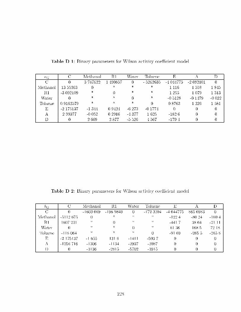
Table D��� Binary parameters for Wilson activity coe�cient model�
aij C Methanol R� Water Toluene E A D
C � ������� ��� �� � ������� �������� �������� �Methanol ������ � � � � ����� �� ���
R� ���� ��� � � � � ��� ���� �����Water � � � � � ����� ������ ������Toluene �� ���� � � � � ����� ����� ���
E �������� ������ �� ��� ������ ������� � � �A �� ��� ����� ��� �� ������ ���� ����� � �D � ���� ���� ���� ���� ��� �� � �
Table D��� Binary parameters for Wilson activity coe�cient model�
bij C Methanol R� Water Toluene E A D
C � �������� �� �� � � ��������� �������� ��� � �Methanol ������� � � � � ������ ����� ������
R� �������� � � � � ������ ���� ������Water � � � � � ����� ��� ����Toluene ������� � � � � � ��� ���� ����
E �������� ���� ����� ����� ����� � � �A �������� ����� ����� �� �� ���� � � �D � ����� ��� ���� �� � � � �
��
Appendix E
Stream Data for Carbinol Case
Study
When computing the stream compositions the following assumptions and simpli�ca
tions were made�
� �� conversion of trienone to carbinol�
� A �� loss of carbinol to tetraene�
� All water� acetic acid� and salts are removed in the phase split� No organic
material is lost here�
� The brine is removed completely in the washing� and no organic material is lost
here�
���

Table E��� Stream data for Carbinol case study �kmol per batch��
Component � � � � � �
Trienone � � � ���� ���� � � ����CH�MgBr �� � �� � ��� � ��� �Et�O ���� � ���� � ���� � � ����THF � ���� ���� � ���� � � ����AceticAcid � � � � � �� �� �H�O � � � � � � � �Brine � � � � � � � �Cyclohexane � � � � � � � �Carbinol � � � � ����� � � �����Tetraene � � � � ���� � � ����
Total �� ���� �� ���� �� �� ��� ���
Component �� �� �� �� �� � ��
Trienone � � ���� � � ���� � ����CH�MBr � � � � � � � �Et�O � � ���� � ���� � � �THF � � ���� � ���� �� �� �AceticAcid � � � � � � � �H�O � � � � � � � �Brine �� �� � � � � � �Cyclohexane � � � ��� �� ���� ���� �Carbinol � � ����� � � ����� � �����Tetraene � � ���� � � ���� � ����
Total �� �� ��� ��� ����� ���� ���� ���
���

Appendix F
Stream Data for Benzonitrile
Production
Table F��� Case study �� process � base case �kmol per batch��
Component � � � � � �
Toluene � ��� ��� � ��� � ���Methanol � � � � � � �Acetic Acid � � � � � ���� ���� Ethanol � � � � � � �Water � � ��� ���� ���� � � �� ��R� �� �� � � � � � �I�� � � �� �� � �� �� � �I�� � � � � � � �� ��AR� � � � � � � �
Total �� �� ���� ����� ���� ���� ���� �����
Component �� �� �� ��
Toluene ��� � � � � �Methanol � � ��� � ��� � ��� � �Acetic Acid ���� � � � � �Ethanol � � ��� � ��� � ��� � �Water �� �� � � ��� ���� ���� �R� � � � � � �I�� � � � � � �I�� � �� �� � � � �AR� � � � �� �� � �� ��
Total � �� �� �� ���� �� ���� �� ��
���

Table F��� Case study �� process � base case �kmol per batch��
Component � � � � � �
Toluene � ���� ���� � ���� � ���� ���� �Methanol � � � � � ��� ��� ��� �Ethanol � � � � � ��� ��� ��� �Water � ���� ����� ����� � ���� ����� ����� �R� ���� � � � � � � � �I�� � � ���� � ���� � � � �Ar� � � � � � � ���� � ����
Total ���� � ��� � ��� ��� ����� � �� ���� ���� ����
Table F��� Case study �� integration across process boundaries �kmol per batch��
Compound � � � � � � ��
Methanol � � � � � � ���� ���� � �Ethanol � � � � � � � � � �Water � � ��� � ��� � � �� �� � � �� ���� � �Toluene � ����� ���� � ���� � � � � ���� �Acetic Acid � � � ���� � ���� � � � � ����R� �� �� � � � � � � � �R� � � � � � � � � �
Total �� �� � �� ���� ���� ���� � ������ ����� ����� ���� ����
Compound �� �� �� �� � �� �� � � ��
Methanol � � ���� ����� ���� � � � � �Ethanol � � � � � � � � � �Water � � ���� � � ���� � ���� ����� � � Toluene � � � � � � ��� � � � ����Acetic Acid ������ ���� � � � � � � � �R� � � � � � � � � � �R� � � � � � � � � ���� �
Total ������ ���� ���� ����� ���� ���� ��� � ���� ��� � ����
Compound �� �� �� �� � �� �� � � ��
Methanol � ����� ����� � ����� � � ����� � �����Ethanol � � � � � � � � � �Water � ���� ����� ���� � � � ���� � ���� �Toluene ����� � � � � ��� � � � � �Acetic Acid � � � � � � � � � �R� � � � � � � � � � �R� � � � � � � � � � �
Total ���� � � ��� �� ���� � ����� ��� � ���� ����� ���� ����
���

Table F��� Case study �� process � with no integration across process boundaries�kmol per batch��
Component � � � � � �
Methanol � � � � � � ���� ���� �Ethanol � � � � � � � � �Water � ���� � ��� � � �� �� � ��� ���� ���� Toluene � ���� ���� � ����� � � � � �Acetic Acid � � � � ���� � ���� � � � �R� �� �� � � � � � � � �I�� � � � � � � � � �I�� � � � � � � � � �Ar� � � � � � � � � �
Total �� �� ����� ���� � ����� ���� � ������ ����� ����� ����
Component �� �� �� �� �� � �� ��
Methanol � � � ����� ����� ����� � �Ethanol � � � � � � � �Water � � � ���� � � ��� �Toluene ���� � � � � � � �Acetic Acid � ���� ���� � � � � ����R� � � � � � � � �I�� � � � � � � � �I�� � � � � � � � �Ar� � � � � � � � �
Total ���� ���� ���� ���� ����� ����� ��� ����
���
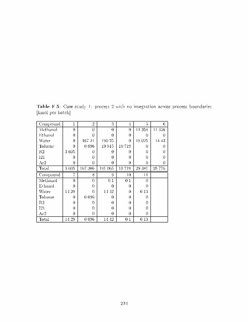
Table F��� Case study �� process � with no integration across process boundaries�kmol per batch��
Compound � � � � �
Methanol � � � � ����� �����Ethanol � � � � � �Water � ������ ���� � ���� �����Toluene � ��� � ���� ����� � �R� ���� � � � � �I�� � � � � � �Ar� � � � � � �
Total ���� ������� � ���� ����� � ��� �����
Compound � �� ��
Methanol � � ��� ��� �Ethanol � � � � �Water ���� � ����� � ����Toluene � ��� � � � �R� � � � � �I�� � � � � �Ar� � � � � �
Total ���� ��� � ����� ��� ����
���

Appendix G
Stream Data for Case Study �
Table G��� Case study �� process � no integration across process boundaries �molper batch��
Compound � � � � � � ��
Methanol � ��� ����� ����� ��� ���� � ��� � �Ethyl Acetate � � � � � � � � � �Toluene � � � � � ����� ���� �� �� ���Iso�Propanol � � � � � � � � � �A ���� � � � � � � � � �B � � � ���� � � � � � �C � � � � � ���� � � � �D � � � � � � � � � �E � � � � � � � � � �F � � � � � � � � � �G � � � � � � � � � �
Total ���� ����� ����� ��� ����� ���� �� � �� ���
���

Table G��� Case study �� process � with no integration across process boundaries�mol per batch��
Compound � � � � � �
Methanol � � � ���� � � �� ��� �� Ethyl Acetate � � � ��� � � ��� � ���Toluene � � � � � � � � �Iso�Propanol � � ����� � ���� � � � �A � � � � � � � � �B � � � � � � � � �C � � � � � � � � �D ���� � � � � � � � �E ���� � � � � � � � �F � � ���� � � � � � �G � � � ���� � � � � �
Total ���� � � ��� ����� ���� � � �� �� � ��
���

Table G��� Case study �� integration across process boundaries �mol per batch��
Compound � � � � � �
Methanol � ����� ����� � ���� �� � �Ethyl Acetate � ���� ��� � � � �Toluene � � � ����� ����� � �� ��Iso�Propanol � � � � � � � �A ���� � � � � � � �B � � ���� � � � � �C � � � � ���� � � �D � � � � � � � �E � � � � � � � �F � � � � � � � �G � � � � � � � �
Total ���� ��� ����� ����� ����� ��� �� ��
Compound �� �� �� �� �� � ��
Methanol ��� � ���� � � � � ����� ��� Ethyl Acetate � � � � � ��� ����Toluene � � � � � �� � � � �Iso�Propanol � � � � � ����� � �A � � � � � � � �B � � � � � � � �C � � � � � � � �D � � � � ���� � � �E � � � � ���� � � �F � � � � � ���� � �G � � � � � � ���� �
Total � � � �� � �� ���� � ��� ���� ����
Compound �� � � �� �� ��
Methanol � � � � ��� �Ethyl Acetate � � � � � �Toluene � � � � � �Iso�Propanol � � ���� � � �A � � � � � �B � � � � � �C � � � � � �D � � � � � �E � � � � � �F � � � � � �G � � � � � �
Total � � ���� � ��� �
���

Table G��� Case study �� alternative �owsheet �mol per batch��
Compound � � � � � � ��
Methanol � ��� ����� � � ���� � � � ��Ethyl Acetate � ���� ��� � ��� � � � � � �Toluene � � � � � � ��� ���� �� Iso�Propanol � � � � � � � � � �A ���� � � � � � � � � �B � � ���� ���� � � � � � �C � � � � � � � � � �D � � � � � � � � � �E � � � � � � � � � �F � � � � � � � � � �G � � � � � � � � � �
Total ���� ��� ����� �� ��� ��� ��� ���� �� �
�� �� �� �� � �� �� � �
Methanol � � � � � ����� �� ���Ethyl Acetate � � � � � ��� ��� ��� �Toluene � � � � � � � � �Iso�Propanol � � ����� ���� � � � � �A � � � � � � � � �B � � � � � � � � �e C � � � � � � � � �D ���� � � � � � � � �E ���� � � � � � � � �F � � ���� � � � � � �G � � � � � � ���� � �
Total ���� � � ��� ���� � ��� � ��� � � ���
��

Bibliography
W� Abrams and J� Prausnitz� Statistical thermodynamics of liquid mixtures� a newexpression for the excess gibbs free energy of partly or completely miscible systems� AIChE Journal� ������� �����
B� S� Ahmad and P� I� Barton� Solvent recovery targeting for pollution preventionin pharmaceutical and specialty chemical manufacturing� AIChE SymposiumSeries� ����������&��� �����
B� S� Ahmad and P� I� Barton� Synthesis of batch processes with integrated solventrecovery and recycling� Presented at AIChE Annual Meeting� Paper No� ���d�November �����
B� S� Ahmad and P� I� Barton� Design of multiproduct batch manufacturing facilitieswith integrated solvent recovery� Presented at th World Congress in ChemicalEngineering San Diego� July �����
B� S� Ahmad and P� I� Barton� Homogeneous multicomponent azeotropic batch distillation� AIChE Journal� �����������&����� �����
R� J� Allgor� M� D� Barrera� P� I� Barton� and L� B� Evans� Optimal batch processdevelopment� Computers chem� Engng� �������� �& ��� �����
Aspen Technology� BATCHFRAC User Manual release ������ Aspen TechnologyInc�� Cambridge� MA ������ USA� �����
Aspen Technology� ASPEN PLUS User Manual Release � Aspen Technology Inc��Cambridge� MA ������ USA� �����
J� P� Aumond� Plantwide solvent identi�cation for pharmaceutical and �ne chemicalprocesses� Technical report� Doctoral Thesis Proposal� Massachusetts Instituteof Technology� �����
R� W� Baker� E� L� Cussler� W� Eykamp� W� K� Koros� R� L� Ryley� and H� Strathmann� Membrane separation systems� Research needs assessment� Technicalreport� U�S� Department of Energy� DEAC�� ER������ April �����
M� D� Barrera and L� B� Evans� Optimal design and operation of batch processes�Chem� Eng� Comm�� ����&��� �� ��
R� C� Berglund and C� T� Lawson� Preventing pollution in the CPI� ChemicalEngineering� September �����
C� Bernot� M� F� Doherty� and M� F� Malone� Patterns of composition change inmulticomponent batch distillation� Chem� Eng� Science�� ����������&����� �����
���

C� Bernot� M� F� Doherty� and M� F� Malone� Feasibility and separation sequencesin multicomponent batch distillation� Chem� Eng� Science�� ������������&����������
A� Brooke� D� Kendrick� and A� Meeraus� GAMS A User�s Guide Release ���� TheScienti�c Press� San Francisco� CA� �����
E� C� Carlson� Don t gamble with physical properties for simulations� ChemicalEngineering Progress� pages ��&��� October �����
N� Chadha and C� S� Parmele� Minimize emissions of air toxics via process changes�Chemical Engineering Progress� pages ��&��� January �����
P� A� Clark and A� W� Westerberg� Optimization for design problems having morethan one objective� Computers chem� Engng� ��������&�� � �� ��
H� T� Clarke and R� R� Read� �tolunitrile and ptolunitrile� Organic SynthesisCollective� �����&���� �����
T� H� Cormen� C� E� Leiserson� and R� L� Rivest� Introduction to Algorithms� McGraw Hill Company� New York� �����
E� W� Crabtree and M� M� ElHalwagi� Synthesis of acceptable reactions� AIChESymposium Series� �����������&���� �����
A� G� Davidyan� V� N� Kiva� G� A� Meski� and M� Morari� Batch distillation in acolumn with a middle vessel� Chemical Engineering Science� ���� ������&����������
K� De Wahl and D� Peterson� Waste reduction in solvent cleaning� Process changevs� recycling� Pollution Prevention Review� Winter �����
U� M� Diwekar and S� E� Zitney� Chemical process simulation technology for solvingenvironmental problems� Presented at AIChE National Meeting Seattle� PaperNo� � b� Summer� �����
U� M� Diwekar� A process analysis approach to pollution prevention� AIChE Sympo�sium Series� ���������� &���� �����
M� F� Doherty and G� A� Caldarola� Design and synthesis of homogeneous azeotropicdistillation �� The sequence of columns for azeotropic and extractive distillations� Ind� Eng� Chem� Fundam�� ������&� �� �� ��
M� F� Doherty and J� D� Perkins� Properties of liquidvapour composition surfacesat azeotropic points� Chem� Eng� Science� �������&����� �����
M� F� Doherty and J� D� Perkins� On the dynamics of distillation processes I�The simple distillation of multicomponent nonreacting� homogeneous liquid mixtures� Chem� Eng� Science� ���� �&���� ��� �
M� F� Doherty and J� D� Perkins� On the dynamics of distillation processes II� Thesimple distillation of model solutions� Chem� Eng� Science� ������&�� � ��� �
M� F� Doherty and J� D� Perkins� On the dynamics of distillation processes III�The topology structure of ternary residue curve maps� Chem� Eng� Science��������&����� �����
���

J� M� Douglas� Conceptual Design of Chemical Processes� McGraw Hill Publishers�New York� �� �
J� M� Douglas� Process synthesis for waste minimization� Ind� Eng� Chem� Res������� &���� �����
R� H� Ewell and L� M� Welch� Recti�cation in ternary systems containing binaryazeotropes� Industrial and Engineering Chemistry� ������������&����� �����
Z� T� Fidkowski� M� F� Malone� and M� F� Doherty� Computing azeotropes in multicomponent mixtures� Computers chem� Engng� �����������&����� �����
E� R� Foucher� M� F� Doherty� and M� F� Malone� Automatic screening of entrainersfor homogeneous azeotropic distillation� Ind� Eng� Chem� Res�� ������� �����
Aa� Fredenslund� J� Gmehling� and P� Rasmussen� Vapor�Liquid Equilibria usingUNIFAC� Elsevier� Amsterdam� �����
H� Freeman� T� Harten� J� Springen� P� Randall� M�A� Currant� and K� Stone� Industrial pollution prevention� A critical review� Journal for Air and WasteManagment Association� �������� &���� �����
S� K� Friedlander� The implications of environmental isssues for engineering R ' Dand education� Chemical Engineering Progress� pages ��&� � November �� ��
J� Ghemling� U� Onken� and W� Arlt� Vapor�Liquid Equilibrium Data Collection�DECHEMA� ���� Frankfurt�Main� F�R�Germany� �� ��
P� H� Groggins� Unit Processes in Organic Synthesis th ed� McGrawHill� Inc�� NewYork� ��� �
I� E� Grossman� R� Drabbant� and R� K� Jain� Incorporating toxicology in the synthesis of industrial complexes� Chem� Eng� Comm�� ������&���� �� ��
J� Guckenheimer and P� Holmes� Nonlinear Oscillations Dynamical Systems andBifurcations of Vector Fields� SpringerVerlag� �� ��
J� Hale and H� Ko!cak� Dynamics and Bifurcations� SpringerVerlag� �����
S� Q� Hassan and D� L� Timberlake� Steam stripping and batch distillation for theremoval and�or recovery of volatile organic compunds from industrial waste� AirWaste Manage� Assoc�� ������&���� �����
T� Hatipoglu and D� W� T� Rippin� The eects of optimal temperature and feedaddition rate pro�les on batch reactions and sequences of batch operations the development of a catalogue of attainable regions� In Institution of ChemicalEngineering Symposium Series No� ��� pages ���&���� Pergamon Press� �� ��
R� A� Heckman� Alternatives for hazardous industrial solvents and cleaning agents�Pollution Prevention Review� Summer �����
J� G� Hocking and G� S� Young� Topology� AddisonWesley Publishing Company�Inc�� �����
C� S� Hwa� Mathematical formulation and optimization of heat exchanger networksusing separable programming� AIChE�I Chem� E� Symp� Ser�� �����&���� �����
���

IBM Corporation� Optimization Subroutine Library Guide and Referance� IBM Corporation� SC��&����& �����
R� A� Jacobs� Waste minimizationpart �� Design your process for waste minimization�Chemical Engineering Progress� pages ��&��� June �����
E� M� Kirschner� Environment� health concerns force shift in use of organic solvents�Chemical � Engineering News� pages ��&��� June ��� �����
J� P� Knapp� Exploiting Pressure E�ects in the Distillation of HomogeneousAzeotropic Distillation� PhD thesis� University of Massachusets� Amherst� June�����
J� R� Knight and M� F� Doherty� Systematic approaches to the synthesis of separationschemes for azeotropic mixtures� In Proceedings of third International Conferanceon Foundations of Computer�Aided Process Designs� pages ���&���� Snowmass�Colorado� July ���� �� ��
J� P� Knight and G� J� McRae� An approach to process integration based on thechoice of system chemistry� Presented at AIChE Annual Meeting� Paper No���d� November �����
J� P� Knight� Computer�Aided Design Tools to Link Chemistry and Design in ProcessDevelopment� PhD thesis� Massachusetts Institute of Technology� �����
A� Lakshmanan and L� T� BIegler� Reactor network targeting for waste minimization�AIChE Symposium Series� ���������� &�� � �����
S� G� Levy� D� B� Van Dongen� and M� F� Doherty� Design and synthesis of homogeneous azeotropic distillation �� Minimum re�ux calculations for nonideal andazeotropic columns� Ind� Eng� Chem� Fundam�� ������&���� �� ��
A� A� Linninger� S� A� Ali� E� Stephanopoulos� C� Han� and G� Stephanopoulos�Synthesis and assessment of batch processes for pollution prevention� AIChESymposium Series� ����������&� � �����
Y� I� Malenko� Physicochemical analysis of fractional distillation diagrams� I� Theoretical basis of method� Russ� J� Phys� Chem�� ������ ��& ��� �����
Y� I� Malenko� Physicochemical analysis of fractional distillation diagrams� II� Quaternary systems� Russ� J� Phys� Chem�� ���������&���� �����
Y� I� Malenko� Physicochemical analysis of fractional distillation diagrams� III� Multicomponent �ncomponent� systems� Russ� J� Phys� Chem�� ���������&���� �����
C� D� Maranas� C� M� McDonald� S� T� Harding� and C� A� Floudas� Locatingall azeotropes in homogeneous azeotropic mixtures� Computers chem� Engng����Suppl�A��S���&S�� � �����
H� Matsuyama and H� Nishimura� Topological and thermodynamic classi�cation ofternary vaporliquid equilibria� J� Chem� Eng� Japan� ���� �� �����
L� K� Molnar� Polymer�Based Solvent for Minimizing Pollution during the Synthesisof Fine Chemicals� PhD thesis� Massachusetts Institute of Technology� �����
Y� Naka� T� Komatsu� I� Hashimoto� and T� Takamatsu� Changes in distillationcomposition during ternary azeotropic batch distillation� Int� Chem� Engng��������&���� �����
���

F� B� Petlyuk� V� Ya� Kievskii� and L� A� Sera�mov� Thermodynamic and topologic analysis of the phase diagrams of polyazeotropic mixtures� I� De�nition ofdistillation regions using a computer� Russ� J� Phys� Chem�� �������� ��&� ��������
F� B� Petlyuk� V� Ya� Kievskii� and L� A� Sera�mov� Thermodynamic and topologicanalysis of the phase diagrams of polyazeotropic mixtures� II� Algorithm forconstructing of structural graphs for azeotropic ternary mixtures� J� of Am�Chem� Soc�� �������� ��&� ��� �����
F� B� Petlyuk� V� Ya� Kievskii� and L� A� Sera�mov� Thermodynamic and topologicanalysis of the phase diagrams of polyazeotropic mixtures� V� The use of thephase equilibrium model in combined thermodynamic and topological analysis�J� of Am� Chem� Soc�� �������� &���� �����
E� N� Pistikopoulos� S� K� Stefanis� and A� G� Livingston� A method for minimum environmental impact analysis� AIChE Symposium Series� �����������&���� �����
J� M� Prausnitz� R� N� Lichtenhaler� and E� G� Azevedo� Molecular Thermodynamicsof Fluid�Phase Equilibria �nd ed� PrenticeHall� Engelwood Clis� N�J�� �� ��
C� Reichardt� Solvents and Solvent E�ects in Organic Chemistry �nd ed� VCHVerlagsgesellschaft mbH� Germany� �� �
R� C� Reid� J� M� Prausnitz� and B� E� Poling� The Properties of Gases and Liquids�th ed� McGrawHill� Inc� New York� �� ��
W� Reinders and C� H� De Minjer� Vapourliquid equilibrium in ternary systems�Recl� Trans� Chim�� ������&���� �����
G� V� Reklaitis� Progress and issues on computer aided batch process design� InProceedings Third International Conferance on Foundations of Computer�AidedProcess Design� pages ���&���� Snowmass� Colorado� �� ��
H� Renon and J� M� Prausnitz� Local compositions in thermodynamic excess functionsfor liquid mixtures� AIChE Journal� ���������&���� ��� �
D� W� T� Rippin� Design and operation of multiproduct and multipurpose batchchemical plants� Computers Chem� Engng�� ��������&� �� �� ��
D� W� T� Rippin� Review paper� Simulation of single and multiproduct batch chemical plants for optimal design and operation� Computers Chem� Engng�� ��������&���� �� ��
D� W� T� Rippin� Batch process systems� A retrospective and prospective review�Computers Chem� Engng�� ���S�&S��� �����
A� P� Rossiter� Process integration and pollution prevention� AIChE SymposiumSeries� ����������&��� �����
W� Rudin� Principles of Mathematical Analysis� McGrawHill� Inc�� New York� �����
B� T� Safrit and A� W� Westerberg� Algorithm for generating the distillation regionsfor azeotropic multicomponent mixtures� Presented at AIChE Spring MeetingNew Orleans� Paper No� ��b� February �����
���

B� T� Safrit� A� W� Westerberg� U� Diwekar� and O� M� Wahnschat� Extendingcontinuous conventional and extractive distillation feasibility insights to batchdistillation� Ind� Eng� Chem� Res�� �������&����� �����
H� E� Salomone and O� A� Iribarren� Posynomial modeling of batch plants� A procedure to include process decision vaiables� Computers Chem� Engng�� ���������&� �� �����
L� A� Sera�mov� F� B� Petlyuk� and I� B� Aleksandrov� The number of trajectory clusters representing continuous recti�cation of azeotropic multicomponent mixtures�Theor� Found� Chem� Eng�� � ��& ��� �����
R� A� Sheldon� Consider the environmental quotient� CHEMTECH� pages � &���March �����
Shell� Shell Brie�ng Service Report on Petrochemicals� Shell Brie�ng Service� �����
S� Skogestad� B� Wittgens� E� S(rensen� and R� Litto� Multivessel batch distillation�Presented at AIChE Annual Meeting� Paper No� ���i� November �����
J� Stichlmair and J� R� Herguijuela� Separation regions and processes of zeotropicand azeotropic ternary distillation� AIChE Journal� � �����&����� �����
J� Stichlmair� H� Oers� and R� W� Pottho� Minimum re�ux and minimum reboilin ternary distillation� Ind� Eng� Chem� Res�� ������ &����� �����
S� C� Stinson� Custom chemicals� C � EN� pages ��&��� February � �����
A� Streitwieser� C� H� Heathcock� and E� M� Kosower� Introduction to Organic Chem�istry� MacMillian Publishing Company� USA� �����
S� H� Strogatz� Nonlinear Dynamics and Chaos� AddisonWesley Publishing Company� �����
W� Swietoslawski� Azeotropy and Polyazeotropy� Pergamon Press� Oxford� �����
C� H� Twu and J� E� Coon� Accurately estimate binary interaction parameters�Chemical Engineering Progress� pages ��&��� December �����
T� Umeda� A� Hirai� and A� Ichikawa� Synthesis of optimal processing systems by anintegrated approach� Chem� Engng� Sci�� ������& ��� �����
U�S� Congress� Resource Conservation and Recovery Act� �� ��
U�S� Congress� Clean Air Act Amendments� P�C� ������� �����
U�S� Congress� Pollution Prevention Act� �����
U�S� Environmental Protection Agency� Pharmaceutical industry� hazardous wastegeneration� treatment� and disposal� NTIS referance� PB�� ��� �����
D� B� Van Dongen and M� F� Doherty� On the dynamics of distillation processes V� The topology of the boiling temperature surface and its relation to azeotropicdistillation� Chem� Eng� Science� ��� �& ��� �� ��
D� B� Van Dongen and M� F� Doherty� Design and synthesis of homogeneousazeotropic distillation �� Problem formulation for a single column� Ind� Eng�Chem� Fundam�� ������&���� �� ��
���

D� B� Van Dongen and M� F� Doherty� On the dynamic of distillation processesVI�Batch distillation� Chem� Eng� Science� ����� �&����� �� ��
O� M� Wahnschat� J� W� Koehler� E� Blass� and A� W� Westerberg� The product composition regions of singlefeed azeotropic distillation columns� Ind� Eng�Chem� Res�� �������&����� �����
O� M� Wahnschat� J� P� LeRudulier� and A� W� Westerberg� A problem decomposition approach for the synthesis of complex separation processes with recycle�Ind� Eng� Chem� Res�� �������� �����
S� Watson� X� Joulia� S� Macchietto� J� M� Le Lann� G� Vayrette� and J� J� Letourneau�Azeotropic distillation� New problems and some solutions� Computers chem�Engng� ���s� �&s���� �����
J� A� Wilson� Dynamic model based optimization in the design of a batch processinvolving simultaneous reaction and distillation� In Institution of Chemical En�gineering Symposium Series No����� pages ���&� �� Pergamon Press� �� ��
J� Wisniak� Liquid�liquid Equilibrium and Extraction� A Literature Source Book V���Elsevier Scienti�c Pub� Co�� �� ��
Y� Zhang� Development and implmentation of algorithms for pollution prevention inpharmaceutical and specialty chemical manufacturing� Technical report� Massachusetts Institute of Technology� December �����
���
![Solvent-free synthesis of (poly)thiacalix[n]arenes: the ...](https://static.documents.pub/doc/80x56/61bd2df161276e740b101f07/solvent-free-synthesis-of-polythiacalixnarenes-the-.jpg)


