Long ago, many workers accidentally observed carbon nanomaterials and fibers in thedeposits inside furnaces dealing with hydrocarbon gases. Iley and Riley [1] observedfilaments of carbon, whereas Davis et al. [2,3] reported graphitic helics. Bacon [4,5] foundfilamentous whiskers of carbon, whereas Hillert and Lange [6] reported interconnected loopsof carbon filaments. These products were found growing on graphite rods, quartz tubes,ceramic tubes (shielding thermocouples), fire bricks and other materials of iron, cobalt,nickel, etc. present in the reaction zone. A wide range of sizes has been found in experimentsat 350–3600°C: 0.01–200mm thick and 0.1–5 cm long. However, it was the discovery of thefullerene family by Kroto et al. [7] and their macroscopic preparation by Kratschmer et al.[8] in the past decade that opened up new opportunities for producing unique carbon-basedmaterials, especially carbon fibers and nanotubes. These nanomaterials have a variety ofapplications in industry, nuclear research, medical science, etc. Recently, high-resolutiontransmission electron microscopy (HRTEM) has revealed many interesting properties ofcarbon nanotubes, which are expected to have novel mechanical and electrical applications.Nevertheless, due to the limitation in producing them in large quantity, their potentiality hasnot been fully utilized. Nowadays, carbon fibers are being fabricated by carbonization ofsynthetic polymers, viz., polyacrylonitril [9], meso pitch [10], and coaltar pitch [11], or bypyrolysis of, for example, acetylene [12] or methane [13] at temperatures ranging from1000–2500°C, using certain catalysts [14] in the presence of hydrogen or argon gas. Most ofthese processes are, however, either unsuitable for large production or expensive. Hence,there is a need to find a cheap source and a simple technique to synthesize carbon nanoma-terials.
Recently, Sharon et al. [15–20] have reported that organic materials possessing carbonatoms with bothsp2 andsp3 and configurations can be most suitable precursors for producingalmost all nanoforms of carbon. They have produced fullerenes [15], nanotubules [16], glassycarbon [17], and diamond-like carbon [18] from pyrolysis of pure camphor, a naturalprecursor of carbon. They have also developed a photovoltaic cell [19] and a photoelectro-chemical solar cell [20], using doped semiconducting carbon films grown from camphor.
Along the same line, we thought that kerosene, a residue of the petroleum refinery,containing a mixture of various short and long chains of aromatic and aliphatic hydrocarbons,might be a useful precursor for preparing various nanoforms of carbon. This paper reports theresults of our effort made in this direction and describes the growth of some of the typicalforms of carbon nanomaterials, viz., conducting fibers, nanotubes, and thin films of carbon,from the pyrolysis of kerosene vapor. Also, the electrochemical application of conductingcarbon thin film in the chloro-alkali industry is discussed.
EXPERIMENTAL
Pyrolysis of kerosene was conducted in a quartz tube held horizontally in a furnace main-tained at 1000°C. Commercial kerosene within a round-bottom flask was heated thermostat-ically at about 90°C, and the vapor, along with a steady flow of argon gas, was allowed topass through the quartz tube. The experimental arrangement of this technique is similar tothat used for camphor source [17]. As substrates, rectangular plates of stainless steel wereplaced in the center of the quartz tube. After 2 h of pyrolysis, the furnace was cooled and the
792 M. KUMAR et al. Vol. 34, No. 5
substrates were removed. Straight and stiff long fibers, flexible, thin hair-like threads, andsoft wool-like clusters of carbon were found clogged around the stainless steel plates uponwhich a uniform carbon film had deposited. A rather shiny film of carbon was deposited onthe inner surface of the quartz tube, and a black powder was also present in the tube. Theseproducts were characterized through scanning electron microscopy (SEM; Topcon ABT-150F), transmission electron microscopy (TEM; Hitachi HU-12A), X-ray diffraction (XRD;
FIG. 1An optical micrograph of (A) straight and stiff carbon fibers and (B) soft and flexible hair-likefibers.
FIG. 2A SEM micrograph of a straight long fiber (A in Fig. 1).
793CARBON NANOMATERIALSVol. 34, No. 5
Philips PW-1710), FTIR (Nicolet Instruments Impact-400), and laser-Raman (RamanorHG2S) analyses.
RESULTS AND DISCUSSION
Figure 1 shows an optical micrograph of straight and stiff carbon fibers 5–7 cm long (A) andthin hair-like flexible threads of carbon (B). Though the mechanical strength of theseproducts was not measured quantitatively, they were substantially elastic, as judged bymanual exercise. As observed from their scanning electron micrographs (Figs. 2 and 3), thestraight and stiff fibers were about 70–75mm thick, whereas the flexible hair-like fibers were2 mm thick.
A low-magnification TEM micrograph of a soft wool-like cluster of carbon fiber is shownin Fig. 4. This figure reveals three types of basic structures involved with the as-grown fiberformation: A, thick twisted fibers; B, irregularly shaped fibers of medium thickness; and C,thin fibers with comparatively uniform surface. A magnified TEM micrograph of this sample(Fig. 5) reveals the thickness of these basic structures: 200–250 nm for A, 100–125 nm forB, and 60–70 nm for C. This micrograph also suggests that fibers A and B are solid, whereasfibers C are hollow.
An enlarged view of structure A (Fig. 6) reveals it to be a coaxial aggregation of a numberof nanodisks 50–60 nm thick. The electron diffraction pattern shown in Fig. 6 confirms thatthe axis of the as-grown fiber coincides with thec axis of the graphite structure. On the otherhand, an enlarged TEM micrograph of structure C (Fig. 7) shows it to be a fairly uniformnanotube, with inner and outer diameters of 3 and 80 nm, respectively. Figure 8 shows anenlarged SEM micrograph of a bitter-gourd-like rough fiber, which is obviously a lateralaggregation of the three structure types, i.e., A, B, and C, as assigned above (Figs. 4 and 5).
FIG. 3A SEM micrograph of hair-like fibers (B in Fig. 1).
794 M. KUMAR et al. Vol. 34, No. 5
FIG. 4A TEM micrograph of a soft wool-like cluster of carbon composed of (A) thick twisted fibers,(B) irregularly shaped fibers of medium thickness, and (C) thin fibers with comparativelyuniform surface.
FIG. 5A magnified TEM micrograph of wool-like carbon revealing (A) solid fibers (200–250 nm,(B) solid fibers (100–125 nm), and (C) hollow fibers (60–70 nm).
795CARBON NANOMATERIALSVol. 34, No. 5
FIG. 6A magnified TEM micrograph of A (Figs. 4 and 5), revealing a coaxial aggregation ofnanodisks of thickness 50–60 nm. c and c¯ show the1 and2 directions of thec axis. Insetis the electron diffraction pattern.
FIG. 7A magnified TEM micrograph of C (Figs. 4 and 5), showing a uniform nanotube having innerand outer diameters of 30 and 80 nm, respectively.
796 M. KUMAR et al. Vol. 34, No. 5
This supports our analysis that the structure A, B, and C are the basic components ofkerosene-pyrolyzed fibers.
Figure 9 shows the cross-sectional view of a solid fiber exhibiting earthworm-like nano-fibers wrapped in a tubular shell. Figure 10 shows an enlarged view of the so-calledearthworm-like nanofibers. To our knowledge, there is no report on the formation of this typeof fiber by any process.
FIG. 8A SEM micrograph of a bitter-gourd-like rough fiber, revealing a lateral aggregation of basicstructures A, B, and C (Figs. 4 and 5).
FIG. 9Cross-sectional view of a solid fiber revealing earthworm-like nanofibers wrapped in atubular shell.
797CARBON NANOMATERIALSVol. 34, No. 5
This is the first time that carbon fibers and nanotubes have been produced from kerosene.Further, to the best of our knowledge, this is the first report of production of conducting fibersup to 7 cm in length from the pyrolysis of any hydrocarbon. Such long conducting fibers mayhave many applications in biosensors, ion-activated molecular switches, and microelectrodesfor medical uses. The hair-like and wool-like fibers may be used in making composite fibers.Bearing an extremely irregular outer surface, the bitter-gourd-like fibers are expected to givea very large surface area for catalytic applications. As kerosene is the cheapest petroleumproduct, production of these fibers from kerosene will be very economical.
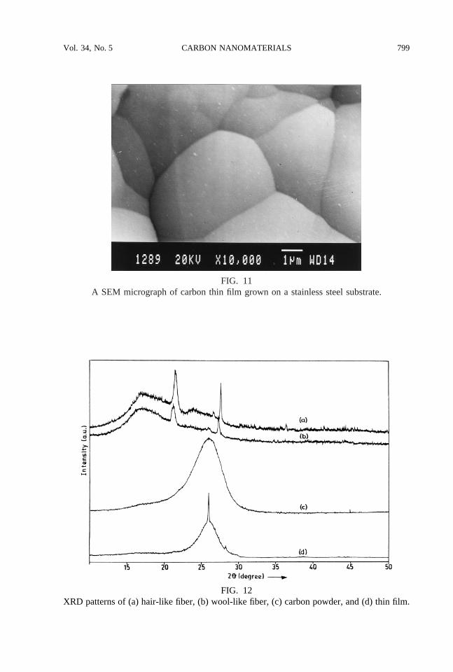
Figure 11 shows a SEM micrograph of a thin film of carbon as deposited on a stainlesssteel substrate that was placed inside the quartz tube. A very well-developed and closelypacked structure is observed. Quite interestingly, the surface morphology of this thin film issimilar to that of the straight long fibers (Fig. 2).
In order to correlate apparently different forms of carbon obtained from the pyrolysis ofkerosene, an XRD study of the hair-like and wool-like fibers, carbon powder, and thin filmswas carried out. XRD patterns (Fig. 12) revealed that the wool-like and hair-like fiberspossess identical structure (which suggests that the latter may be a modification of theformer), whereas powder and thin films are, crystallographically, a little different. This is notsurprising if we take into consideration that the substrate was stainless steel, a complexcatalyst of different compositions and crystallographic orientations. It is, however, interestingto note that the as-obtained lattice parameters do not match with that of graphite or any otherknown form of carbon, suggesting that kerosene-pyrolyzed carbon nanomaterials have anovel structure. That is, the starting material, kerosene, does play a significant role in theformation of these nanocarbon products. The interplanar distances (d-values) obtained fromthe carbon powder were found to fit into a hexagonal lattice arrangement with a unit-cell sizeof a 5 b 5 7.012 Å andc 5 20.088 Å, using the POWD program [21].
The FTIR spectrum (not shown here) of carbon powder obtained from the pyrolysis ofkerosene exhibited two peaks, at 2861.4 and 2933.8 cm21, respectively, which correspond toC–H stretching forsp3- andsp2-bonded carbon atoms, respectively. These values are in good
FIG. 10An enlarged view of the earthworm-like nanofibers.
798 M. KUMAR et al. Vol. 34, No. 5
FIG. 11A SEM micrograph of carbon thin film grown on a stainless steel substrate.
FIG. 12XRD patterns of (a) hair-like fiber, (b) wool-like fiber, (c) carbon powder, and (d) thin film.
799CARBON NANOMATERIALSVol. 34, No. 5
agreement with the reported IR absorption for C–H stretching vibrations [22]. From the areaand peak calculations of the FTIR spectrum, the ratio ofsp3 andsp2 carbon contents in thesample was found to be 3:17. The incorporation ofsp3 carbon into the kerosene-pyrolyzedsamples may be a reason for its deviation from the graphitic structure.
The laser-Raman spectrum of an as-grown carbon film was scanned in the wavenumberrange 1000–1900 cm21. However, no characteristic peak appeared in the vicinity of 1357and 1583 cm21 (responsible for glassy carbon) or 1580 cm21 (responsible for graphite),suggesting that the kerosene-pyrolyzed carbon is neither graphitic nor glassy carbon. Thisagain supports the novelty of the as-grown films.
The room-temperature resistivity of a pellet made from the kerosene-pyrolyzed carbonpowder was found to be of the order of 105 V cm, whereas that of carbon fibers and thin filmswas of the order of 1024 V cm. This suggests that the fibers and films are good conductorsof electricity. A Hall effect study of the films revealed their carrier concentration to be of theorder of 1017 V cm–3 with an n-type conductivity. The carrier mobility was found to be about1.7 3 105 cm2 V21 s21.
Based on the present study, the formation of as-grown nanomaterials and their interrelationare well understood, but the detailed reaction kinetics and growth mechanism of kerosene-pyrolyzed carbon products on catalysis is still difficult to explain because there is no singletheory that applies to both nucleation and particle formation. Among the existing theories ofcarbon formation, a few apply to “nucleation” and a few others are applicable to “particlegrowth” [23,24]. These two processes are certainly governed by different laws. The authors,therefore, are looking for an appropriate mathematical theory and trying to formulate a newmodel to explain the precise reaction kinetics and growth mechanism of kerosene-pyrolyzedcarbon products. The extent to which the different parts of complex hydrocarbon moleculespresent in kerosene are involved in the formation of fibers on catalysts, however, can bedetermined by the use of isotopic tracer techniques [25–27].
The electrochemical behavior of the thin film of carbon was investigated, to explore thepossibility of this material’s application as an inert electrode in electrochemical cells. It wasobserved that the electrochemical potential of this material ranged from21.24 to 1.67 V vs.SCE. This means that water is not electrolyzed within this potential range. The suitability ofthis electrode for the electrolysis of brine solution was also examined. It was observed thatthese electrodes could be used to electrolyze 30% NaCl solution at 300 mA cm22 for morethan 110 h of continuous operation without any deterioration. This study is still in progress.Further, in the chloro-alkali industry, at present, an expensive RuO2-coated titanium sheet isused as anode against a mercuric cathode, which causes toxicity problems. It is suggested thatkerosene-pyrolyzed carbon electrodes may be used as both anode and cathode, thus reducingthe electrode-cost, as well as eliminating the possibility of hazardous mercury contamination.
CONCLUSIONS
Kerosene appears to be one of the cheapest precursors for producing various nanoforms ofcarbon. Pyrolysis of kerosene may be considered as a convenient technique for makingcarbon nanotubes and fibers commercially. This is the first exploratory investigation ofsynthesis of carbon nanomaterials from kerosene; further optimization of the preparativeparameters to result in a desired product of definite dimensions is required. The carbon thin
800 M. KUMAR et al. Vol. 34, No. 5
films obtained from kerosene may also become one of the best inert electrodes for electro-chemical investigations and a cheap electrode for the production of caustic soda in thechloro-alkali industry.
ACKNOWLEDGMENTS
The authors are grateful to Michael Neumann-Spallart of CNRS, France, for recording XRDpatterns (Fig. 12) of our samples. Mukul Kumar takes this opportunity to thank Dr. P. N.Singh, Degree College, Chapra (Bihar), India, for relieving him for this project at I.I.T.,Bombay.
REFERENCES
1. R. Iley and H.L. Riley,J. Chem. Soc., 1362 (1948).2. W.R. Davis, R.J. Slawson, and G.R. Rigby,Nature171, 756 (1953).3. W.R. Davis, R.J. Slawson, and G.R. Rigby,Trans. Brit. Ceram. Soc.56, 67 (1957).4. R. Bacon and J.C. Bowman,Am. Phys. Soc. Ser.11 (2), 131 (1957).5. R. Bacon,Am. Phys. Soc. Ser.11 (3), 108 (1958).6. M. Hillert and N. Lange,Z. Kristallogr. 111, 24 (1958).7. H.W. Kroto, J.R. Heath, S.C. O’Brien, R.F. Curl, and R. Smalley,Nature318, 162 (1985).8. W. Kratschmer, D.L. Lamb, K. Fostiropoulos, and D.R. Huffman,Nature347, 345 (1990).9. E. Fitzer,Carbon27, 621 (1989).
10. B.R. Mehata and E.A. Ogryzlo,Surf. Coat. Technol.43, 80 (1990).11. J. Alkaniz-Monge, D. Cazorla-Amoros, A. Linares-Solano, A. Oya, A. Sakamoto, and K. Hoshi,
Carbon35, 1079 (1997).12. S. Motojima, S. Asakura, M. Hirata, and H. Iwanaga,Mater. Sci. Eng., B34, L9 (1995).13. F.T. Wallenberger, R.J. Diefendorf, K.D. Frischknecht, and P.C. Nordine,Mater. Res. Soc. Symp.
Proc. 349, 51 (1994).14. H.J. Scheibe, A.A. Gorbunov, A.V. Gorbunov, N.V. Klassen, V.I. Konov, M.P. Kulakov, W.
Pompe, and A.V. Prokhorov,Rev. Roum. Phys.34, 941 (1989).15. K. Mukhopadhyay, K.M. Krishna, and M. Sharon,Phys. Rev. Lett.72, 3182 (1994).16. K. Mukhopadhyay, K.M. Krishna, and M. Sharon,Carbon34, 251 (1996).17. K. Mukhopadhyay and M. Sharon,Mater. Chem. Phys.49, 105 (1997).18. K. Mukhopadhyay and M. Sharon,Mater. Manuf. Processes12, 541 (1997).19. K. Mukhopadhyay, I. Mukhopadhyay, M. Sharon, T. Soga, and M. Umeno,Carbon 35, 863
(1997).20. M. Sharon, I. Mukhopadhyay, and K. Mukhopadhyay,Sol. Energy Mater. Sol. Cells45, 35
(1997).21. E. Wu, POWD, version 2.2, an interactive powder diffraction data interpretation and indexing
program, School of Physical Sciences, Flinders University of South Australia, Bedford Park, SA5042, Australia.
22. Y. Tambe, G. Burkhard, T. Ishikura, K. Tsunoda, H. Hasuo, M. Tamaru, H. Tamaru, A. Sawaoka,and K. Uematsu,Jpn. J. Appl. Phys.33, 6684 (1994).
23. D.W. Gill, BCURA Monthly Bull.22, 487 (1958).24. A.G. Gaydon and H.G. Wolfhard,Flames, Their Structure, Radiation and Temperature, 2nd ed.,
Chapman and Hall, London (1960), Chap. 8.25. R.W. Blue and C.J. Engle,Ind. Eng. Chem.43, 494 (1951).26. R.E. McMohan,Ind. Eng. Chem.47, 844 (1955).27. M.M. Melik-Zade, M.R. Musaev, N.G. Buzova, and I.G. Safaralieva,Kinet. Katal.2, 745 (1961).