Accepted Manuscript Title: Synthesis of nickel oxide nanoparticles supported on SiO 2 by sensitized liquid phase photodeposition for applications in catalytic ozonation Author: Julia L. Rodr´ ıguez Miguel A. Valenzuela Hugo Tiznado Tatiana Poznyak Evelyn Flores PII: S1381-1169(14)00166-6 DOI: http://dx.doi.org/doi:10.1016/j.molcata.2014.04.028 Reference: MOLCAA 9090 To appear in: Journal of Molecular Catalysis A: Chemical Received date: 22-2-2014 Revised date: 20-4-2014 Accepted date: 21-4-2014 Please cite this article as: J.L. Rodr ´ iguez, M.A. Valenzuela, H. Tiznado, T. Poznyak, E. Flores, Synthesis of nickel oxide nanoparticles supported on SiO 2 by sensitized liquid phase photodeposition for applications in catalytic ozonation, Journal of Molecular Catalysis A: Chemical (2014), http://dx.doi.org/10.1016/j.molcata.2014.04.028 This is a PDF file of an unedited manuscript that has been accepted for publication. As a service to our customers we are providing this early version of the manuscript. The manuscript will undergo copyediting, typesetting, and review of the resulting proof before it is published in its final form. Please note that during the production process errors may be discovered which could affect the content, and all legal disclaimers that apply to the journal pertain.
Transcript
Accepted Manuscript
Title: Synthesis of nickel oxide nanoparticles supported onSiO2 by sensitized liquid phase photodeposition forapplications in catalytic ozonation
Author: Julia L. Rodrıguez Miguel A. Valenzuela HugoTiznado Tatiana Poznyak Evelyn Flores
To appear in: Journal of Molecular Catalysis A: Chemical
Received date: 22-2-2014Revised date: 20-4-2014Accepted date: 21-4-2014
Please cite this article as: J.L. Rodriguez, M.A. Valenzuela, H. Tiznado, T. Poznyak, E.Flores, Synthesis of nickel oxide nanoparticles supported on SiO2 by sensitized liquidphase photodeposition for applications in catalytic ozonation, Journal of MolecularCatalysis A: Chemical (2014), http://dx.doi.org/10.1016/j.molcata.2014.04.028
This is a PDF file of an unedited manuscript that has been accepted for publication.As a service to our customers we are providing this early version of the manuscript.The manuscript will undergo copyediting, typesetting, and review of the resulting proofbefore it is published in its final form. Please note that during the production processerrors may be discovered which could affect the content, and all legal disclaimers thatapply to the journal pertain.
98%), and 2,4-dichlorophenol (Sigma Aldrich, 99%). Anhydrous ethanol and acetone (J.T. Baker) were 87
spectrophotometric grade. SiO2 (CAB-O-SIL, BET surface area = 179 m2 g-1) was used as support.88
2.2. Catalyst preparation89
2.2.1. Liquid phase photodeposition method90
A solution of Ni(acac)2 (8*10-4 M) in alcoholic medium with acetone or benzophenone (10-3 M), as sensitizers, was 91
used in all the experiments. In the glass reactor was also added a dose of SiO2 (0.1 g L-1) at 25°C and the suspension 92
was purged with nitrogen. During the photoreaction, the suspension was subjected to a vigorous and continuous 93
stirring with the aim to avoid the sedimentation of SiO2. The mixture was irradiated with 14 blacklight UVA lamps 94
(8 W) which have a maximum emission at about 365 nm. After irradiation, the sample was dried at 120°C to 95
evaporate the solvent. The kinetics of the Ni(acac)2 photodecomposition was performed by using a Lambda UV-Vis 96
spectrophotometer (Perkin Elmer) at wavelength of 310 nm.97
2.2.2. Impregnation method98
NiO/SiO2 (I) catalyst was prepared by the wetness impregnation method with SiO2 and Ni(acac)2 in ethanol solution 99
(5 wt%). After impregnation samples were dried during 12 h at 110°C, calcined during 2 h at 500°C and finally 100
reduced during 1 h at 500°C. 101
Page 4 of 20
Accep
ted
Man
uscr
ipt
4
2.3. Characterization techniques102
TEM images were obtained using a JEOL-JEM-2200 field emission operated a 200 kV. The samples were prepared 103
with the catalyst (< 1 mg) in methanol and dispersed by ultrasound for 5 min. Thereafter, a drop of the solution was 104
placed over a carbon coated Cu grid (300 mesh) and dried at room temperature. 105
Photoelectron core-level spectra of the as-prepared samples were obtained with an X-ray photoelectron spectroscopy 106
(XPS) system (ThermoFisher Scientific K-Alpha), with a monochromatized AlKα X-ray source (1487 eV). The base 107
pressure of the system was 10-9 mbar. Prior to XPS analysis, all samples were dried at 100°C for 24 h. Subsequently, 108
they were dispersed and embedded in a 5 x 5 mm indium foil and fixes with Cu double side tape to the sample 109
holder. Narrow scans were collected at 60 eV analyzer pass energy and a 400 μm spot size. The position of the C1s 110
peak at 284.6 eV was monitored on each sample to ensure that no binding energy shift due to charging had occurred. 111
The spectra were decomposed into their components with mixed Gaussian–Lorentzian lines by a non-linear least 112
squares curve-fitting procedure, using the public software package XPSPEAK 4.1. The binding energies and FWHM 113
of the peaks were determined from the fitting results after subtraction of the Shirley-type background. Deconvoluted 114
peak areas and standard sensitivity factors were used to evaluate the surface composition of the samples. The pH of 115
zero charge or isoelectric point (pHpzc) was obtained when the zeta potential was zero. The zeta potential of catalysts 116
was determined by Malvern Zeta-Sizer at 25 °C using the titration method with HCl (0.01 N).117
2.4. Ozonation procedure118
Ozone was generated from dry oxygen by the ozone generator (corona discharge type) HTU500G (AZCO Industries 119
Limited–Canada). The Ozone Analyzer BMT 964 BT (BMT Messtechnik, Berlin) provides the ozone monitoring in 120
the gas phase at the reactor outlet for the control of the ozonation degree, the ozone consumption and the ozone 121
decomposition as well. All experiments with ozone were carried out in a semi-batch type reactor (0.5 L) at 21°C. The 122
agitation was provided by means of an ozone-oxygen mixture bubbling through a ceramic porous filter, which is at 123
the bottom of the reactor. The initial ozone concentration was 25 mg L-1. The ozone-oxygen mixture flow was 0.5 L 124
min-1. The flow diagram of the ozonation procedure is described in our previous publication [8]. 125
2.5. Analytical methods126
The model solution of 2,4-D herbicide was prepared with a concentration of 80 mg L-1. The catalyst concentration 127
was constant at 0.1 g L-1. Aliquot of 3 mL ozonation reaction solution was withdrawn at time intervals from the 128
reactor for sequent analysis. UV-VIS absorption spectrums of 2,4-D were measured with Lambda UV-Vis 129
spectrophotometer (Perkin Elmer). A HPLC apparatus (Perkin-Elmer series 200, UV/Vis detector) was used to 130
record the change of concentration of 2,4-D, under the following operation conditions: Prevail Organic Acid (Grace) 131
with mobile phase of KH2PO4 (25Mm) at pH 2.63 adjusted with phosphoric acid : acetonitrile (60:40) with a flow of 132
1 mL min-1 at wavelength of 225 nm.133
3. Results and discussion134
3.1. Sensitized photodeposition of nickel oxide135
Page 5 of 20
Accep
ted
Man
uscr
ipt
5
Fig. 1A shows the evolution of the Ni(acac)2 normalized concentration as a function of irradiation time for 136
photosensitized and photodeposition reactions. It is important to note that only in the presence of photosensitizers the 137
irradiation with UV-light (λ= 365 nm) of the Ni(acac)2 solution changed its original color (light green) to dark brown, 138
indicating the formation of Ni nanoparticles (Fig. 1B). It is clear from these results that benzophenone presented a 139
better performance as a photosensitizer to decompose of Ni(acac)2 compared to acetone (without SiO2). On the other 140
hand, an improved decomposition of Ni(acac)2 was also observed with the mixture of the photosensitizer and SiO2. 141
Note that the initial rate of Ni(acac)2 decomposition followed the same trend with both photosensitizers, however, it 142
was totally different at long reaction times. Indeed, in all photosensitized reaction a very low conversion of the Ni 143
precursor was detected (ca. 50% for benzophenone in presence of SiO2). This behavior could be explained in terms 144
of the complex reaction mechanism of Ni(acac)2 decomposition which forms many intermediate compounds and 145
byproducts inhibiting the main reaction.146
0 1 2 3 4 5 6 70.0
0.1
0.2
0.3
0.4
0.5
0.6
0.7
0.8
0.9
1.0
C/C
0
Time, h
Photosensitized reaction Acetone Benzophenone
In presence of SiO2
Acetone Benzophenone A
147
148
0 h 2 h 8 h NiO/SiO2(P)149
Fig. 1 A. Evolution of the dimensionless concentration of Ni(acac)2 with irradiation time in presence of sensitizer 150(AC=acetone, BP= benzophenone) and SiO2 or without it. B. Effect of color changes in the precursor solution at 151different irradiation time. Experimental condition: [Ni(acac)2= 8x10⁻⁴ M, [AC] = 0.2 M, [BP]= 10–3 M, λ = 365 nm.152
B
Page 6 of 20
Accep
ted
Man
uscr
ipt
6
Fig. 1A displays also two important differences in the photosensitized reduction in presence of SiO2: i) the 153
dimensionless concentration profiles changed from linear to quadratic, and ii) an increased decomposition of the 154
precursor around of 20% with both sensitizers. Worth mentioning that the SiO2 acted only as support, it did not 155
participate directly in the reaction. The precursor photodecomposition was improved with SiO2 due to a reduction of 156
turbidity solution and light can penetrate the solution promoting the decomposition of precursor, since some nickel 157
nanoparticles were deposited on SiO2. In spite of the presence of SiO2, the Ni(acac)2 photodecomposition was not 158
complete. 159
According to our results and previously reported studies on LPPD [8,10], the scheme 1 shows the proposed reaction 160
mechanism in presence of benzophenone.The benzophenone (BP) is excited to singlet excited stated during the 161
irradiation by UV light. The singlet excited stated decays to the triplet excited state via intersystem crossing (1) and 162
one hydrogen atom is abstracted from the hydrogen donor, in this case ethanol, to generate two ketyl radicals and 163
radicals derived from alcohol (2,3). The next step involves the photolytic dissociation of the ketyl radical to form the 164
anion – radical of BP (4), which has a high negative electrochemical potential and is capable of reducing metal 165
cations, (5). The anion radical of BP reduces Ni(acac)2 which is adsorbed on the support to generate nickel 166
nanoparticles on SiO2 (6) and finally, benzophenone is regenerated and some products of the alcohol decomposition 167
are formed, such as acetaldehyde, among others. 168
Scheme 1. Proposed mechanism for the sensitized photoreduction by benzophenone [10].169
1) Triplet-state formation of benzophenone.170O O
hv
*
171
2) Generation of two ketyl radicals.172O
*OH
+ +CH3HO CH3HO
173
O OH
+ + H3C OCH3HO
174
3) Photolytic dissociation of the ketyl radical.175OH O
+ H+ (4)
176
4) Reduction of Ni(acac)2 by the ketyl anion radical.177
(1)
(2)
(3)
Page 7 of 20
Accep
ted
Man
uscr
ipt
7
O
+ Ni(acac)2 (s)
O
acac+ (5)+ Ni(acac) (s)
178
5) Formation of metallic Ni.179
Ni(acac) (s) acac + Ni(0) (s)(6)
180
It is worth mentioning that metallic nickel was easily reoxidized to NiO after stay in contact with atmospheric air, 181
(see XPS results). The catalyst synthetized by LPPD in presence of benzophenone (NiO/SiO2(P)) was chosen due to 182
show major conversion in the decomposition of the Ni precursor. The NiO/SiO2(P) and the reference catalyst 183
prepared by conventional impregnation (NiO/SiO2(I)) were selected to carry out, both, the characterization and 184
catalytic evaluation. 185
3.2. Catalyst characterization186
NiO/SiO2(P)187
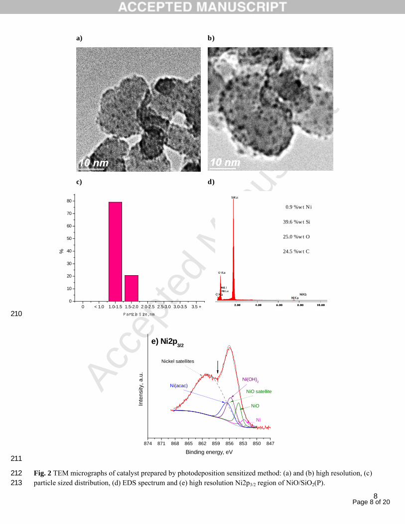
The morphology of the nickel nanoparticles and their distribution on SiO2 was analyzed by TEM. Fig. 2a–b show the 188
high magnified micrographs of NiO/SiO2(P). The bigger and amorphous particles represent the support while the 189
black small areas denote the Ni nanoparticles which consist of nearly spherical geometry. TEM micrograph analysis 190
shows that the particles are distributed homogeneously over the entire support surface. However, the formation of 191
some aggregates is also observed, due to the coalescence of smaller particle during the evaporation of the solvent. It 192
is interesting to note that the micrographs are out of focus intentionally, since under these conditions was possible to 193
observe the nickel nanoparticles. Regarding the histogram of the size distribution reported in Fig. 2c, shows that the 194
diameter of the Ni particles ranges from 1 to 2 nm, with a very narrow monomodal distribution, centered at 1–1.5 195
nm.196
Energy-dispersive X-ray spectroscopy (EDS) permitted to evidence the presence of nickel on the support, Fig. 2d. 197
The nickel amount was obtained by EDS demonstrated that around 0.9 wt% of nickel was deposited on SiO2 which 198
was smaller than the nominal value (5 wt%). This result was reasonable because only a partial photoreduction of 199
precursor was achieved. Moreover, the presence of carbon in the elemental analysis of EDS could be confirmed for 200
the results of XPS. 201
The XPS survey spectrum (not shown) for NiO/SiO2(P) reveals the signals for Si2p, C1s, O1s and Ni2p. These are 202
the main chemical species expected on the catalyst. Since nickel is the most active element of the catalyst, its high 203
resolution spectrum was thoroughly analyzed by deconvolting of the Ni2p3/2 region, Fig. 2e. For the analysis it was 204
taken the reported reference spectra (± 0.2 eV) for pure nickel compounds: metallic Ni (852.9 eV), NiO (853.9 eV), 205
Ni(OH)2 (855.9 eV) and Ni(acac)2 (865.3 eV) [23–26]. The well-known nickel satellites (~ 861 eV) were all included 206
in a single peak; similar procedure has been also reported [24]. Only in the case of NiO, it was included an additional 207
satellite peak in the main peak region as it shows up in the pure compound [23,24]; peak width, intensity ratio and 208
Fig. 2 TEM micrographs of catalyst prepared by photodeposition sensitized method: (a) and (b) high resolution, (c) 212particle sized distribution, (d) EDS spectrum and (e) high resolution Ni2p3/2 region of NiO/SiO2(P).213
0.9 %wt Ni
39.6 %wt Si
25.0 %wt O
24.5 %wt C
Page 9 of 20
Accep
ted
Man
uscr
ipt
9
214
Fig. 2e shows the fitting for the Ni2p3/2 peaks revealing the components: a) metallic Ni, b) Ni2+ ions associated to 215
oxides and hydroxides, such as NiO and Ni(OH)2 and c) Ni(acac)2 related to unreduced precursor. Nonetheless, the 216
synthesis method was capable of producing metallic Ni without the need of thermal treatment. This is an important 217
result, which is corroborated by comparing the fresh and after reaction samples, see Fig. 7d.218
NiO/SiO2(I)219
TEM micrographs and particle size distribution of NiO/SiO2(I) catalyst are shown in Fig. 3a–c. The black areas 220
denote the Ni particles which exhibit a spherical morphology embedded in a SiO2 matrix. TEM micrograph analysis 221
shows that the particle size is in the range from 1 to 3 nm, Fig. 3a. Ni particles are well dispersed over the whole 222
support and the aggregation effect does not remarkably occur, Fig. 3b. The histogram shows monomodal particle size 223
distribution centered at 1.5 – 2.0 nm, Fig. 3c. It is shown clearly, that the particle size distribution in this case was 224
wider compared to the photodeposited catalyst. On the other hand, EDS analysis confirmed the presence of Ni on the 225
SiO2 with an average weight percentage of 4.2% which was very close to the nominal value, Fig. 3d. The Cu signal 226
shown in the EDS spectra was produced by the grid where the sample was placed.227
Although the Ni2p3/2 XPS spectrum for NiO/SiO2(I), Fig. 3e, is similar in overall shape and energy to the one for 228
NiO/SiO2(P), Fig. 2e, a difference can be noticed. The overlap between the main and satellite peaks (pointed out by 229
the arrow) is less prominent in the NiO/SiO2(I) sample. This difference indicates that at least one nickel specie should 230
not be present in this sample. After deconvolution with the same type of peaks applied in the case of the NiO/SiO2(P) 231
fitting, it is clear that the Ni(acac)2 component does not fit the raw data; thus it was removed. This results is not 232
surprising since the high temperature calcination treatment decompose the organic fraction of the Ni(acac)2233
precursor. This also highlights that the proposed Ni(acac)2 component in the deconvolution of the NiO/SiO2(P) 234
spectrum is plausible. On the other hand, the contribution of metallic Ni may seems low (2.3%) as one would expect 235
for a hydrogen treated sample at high temperature. Instead, the major contributions come from oxidized nickel 236
(Ni(OH)2 and NiO). This behavior is not uncommon, it has been reported [27,28] that nickel nanoparticles in air at 237
room temperature forms an oxide layer with an estimated thickness of 2.3 nm. That oxide being composed of an 238
inner layer of NiO and an outer one of Ni(OH)2. In our sample it appears to be an analogous case, given that XPS is 239
especially sensitive to the top most layer and the larger Ni(OH)2 intensity.240
Based on the characterization results of both catalysts, it is worthwhile emphasized that: (i) a bigger amount of 241
nickel nanoparticles were deposited on support using impregnation in comparison with photodeposition method, (ii) 242
about 56% of the Ni particles were in the range of 1–2 nm for impregnation, while 100% of nanoparticles synthetized 243
by photodeposition method were in the above mentioned range, (iii) the range of particle distribution for NiO/SiO2(I) 244
is broader than photodeposition method, (iv) the chemical environment for NiO/SiO2(I) included contributions from 245
Ni(0), NiO and Ni(OH)2 (largest), in the case of NiO/SiO2(P), an extra contribution from unreduced Ni(acac)2 (nickel 246
Fig. 3 TEM micrographs of catalyst prepared by impregnation method: (a) low magnification image and (b) high 250resolution, (c) particle sized distribution, (d) EDS spectrum and (e) high resolution Ni2p3/2 of NiO/SiO2(I).251
4.2 wt% Ni
36.2 wt% Si
47.0 wt%O
12.6 wt% C
Page 11 of 20
Accep
ted
Man
uscr
ipt
11
3.3. Catalyst evaluation252
As is well known, the catalytic ozonation is an alternative route for the elimination of herbicides [29, 30]. Fig. 4 253
shows the concentration profiles and initial rates of the 2,4-D degradation by ozonation in presence of diverse 254
catalysts. It is clear that the herbicide degradation profiles in presence of NiO/SiO2(I) and SiO2 were similar reaching 255
a 80% of herbicide degradation in 8 min. While the efficiency of NiO/SiO2(P) catalyst was slightly higher reaching 256
the same degradation in 7 min. Obviously, the higher initial reaction rates increased with the following trend: 257
NiO/SiO2(P) > NiO/SiO2(I) ≈ SiO2 (attached plot of Fig. 4). Checking the initial specific activity of Ni catalyst, is 258
more evident the higher degradation of the herbicide by using the Ni catalysts prepared by photodeposition (right 259
hand scale in attached plot of Fig. 4).260
As explained before, both catalysts (impregnation and photodeposition) presented small differences in terms of 261
surface chemical composition, morphology, structure and chemical interaction with SiO2. Though the catalytic 262
properties were quite similar with both solids, surprisingly, the best catalyst containing the lesser amount of 263
photodeposited metal was clearly more active than the impregnated catalyst. One explanation of this behavior can be 264
the very narrow particle size distribution of 1-2 nm for NiO/SiO2(P) compared to that obtained for NiO/SiO2(I) of 1-3 265
nm. On the other hand, as the impregnated catalyst was calcined in air flow at 500°C, some of surface Ni atoms could 266
be interacting with the support, diminishing the total amount of active sites available for the reaction. In fact, the 267
photodeposited catalysts did not have any thermal treatment, then, the Ni surface active sites do not interact with the 268
support. This speculation was confirmed by using temperature-programed reduction (not shown here) which showed 269
that the reduction peak of NiO in the photodeposited catalyst was around 200°C, while in the impregnated catalyst 270
was twice.271
0 2 4 6 8 10 12 14 160
10
20
30
40
50
60
70
80
NiO/SiO2 (P) NiO/SiO
2 (I) SiO
2
0.0
1.0x10⁻⁴
2.0x10⁻⁴
3.0x10⁻⁴
4.0x10⁻⁴
5.0x10⁻⁴
6.0x10⁻⁴
7.0x10⁻⁴
8.0x10⁻⁴
- r 0
, mol
gr-1 ca
t min
-1
Catalyst
0.00
0.01
0.02
0.03
0.04
0.05
0.06
0.07
0.08
- r0 , m
ol gr-1N
i min
-1
2,4-
D c
once
ntra
tion,
mg
L-1
Time, min
O3- SiO
2
O3- NiO/SiO
2 (P)
O3 - NiO/SiO
2 (I)
272273
Fig. 4 Comparison of 2,4-D degradation profiles by catalytic ozonation. Insert, initial reaction rates obtained in the 274catalytic ozonation of herbicide in aqueous solution. Experimental conditions: [O3]= 25 ± 3 mg L-1, [Cat] = 0.1 g L-1, 275[2,4-D]= 80 mg L-1, pH = 3.1276
Page 12 of 20
Accep
ted
Man
uscr
ipt
12
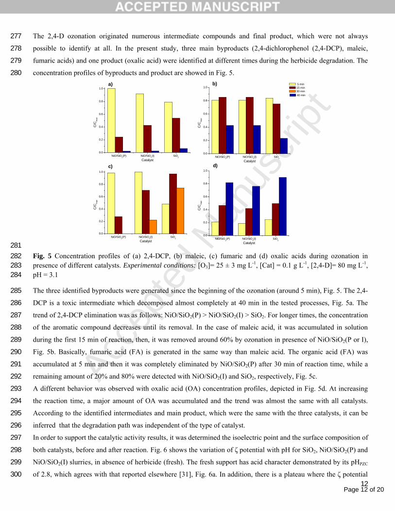
The 2,4-D ozonation originated numerous intermediate compounds and final product, which were not always 277
possible to identify at all. In the present study, three main byproducts (2,4-dichlorophenol (2,4-DCP), maleic, 278
fumaric acids) and one product (oxalic acid) were identified at different times during the herbicide degradation. The 279
concentration profiles of byproducts and product are showed in Fig. 5. 280
NiO/SiO2(P) NiO/SiO
2(I) SiO
2
0.0
0.2
0.4
0.6
0.8
1.0
C/C
max
Catalyst
a)
NiO/SiO2(P) NiO/SiO
2(I) SiO
2
0.0
0.2
0.4
0.6
0.8
1.0b)
C/C
max
Catalyst
NiO/SiO2(P) NiO/SiO
2(I) SiO
2
0.0
0.2
0.4
0.6
0.8
1.0
5 min 15 min 30 min
c)
C/C
max
CatalystNiO/SiO
2(P) NiO/SiO
2(I) SiO
2
0.0
0.2
0.4
0.6
0.8
1.0
d)
C/C
max
Catalyst
40 min
281Fig. 5 Concentration profiles of (a) 2,4-DCP, (b) maleic, (c) fumaric and (d) oxalic acids during ozonation in 282presence of different catalysts. Experimental conditions: [O3]= 25 ± 3 mg L-1, [Cat] = 0.1 g L-1, [2,4-D]= 80 mg L-1, 283pH = 3.1284
The three identified byproducts were generated since the beginning of the ozonation (around 5 min), Fig. 5. The 2,4-285
DCP is a toxic intermediate which decomposed almost completely at 40 min in the tested processes, Fig. 5a. The 286
trend of 2,4-DCP elimination was as follows: NiO/SiO2(P) > NiO/SiO2(I) > SiO2. For longer times, the concentration 287
of the aromatic compound decreases until its removal. In the case of maleic acid, it was accumulated in solution 288
during the first 15 min of reaction, then, it was removed around 60% by ozonation in presence of NiO/SiO2(P or I), 289
Fig. 5b. Basically, fumaric acid (FA) is generated in the same way than maleic acid. The organic acid (FA) was 290
accumulated at 5 min and then it was completely eliminated by NiO/SiO2(P) after 30 min of reaction time, while a 291
remaining amount of 20% and 80% were detected with NiO/SiO2(I) and SiO2, respectively, Fig. 5c.292
A different behavior was observed with oxalic acid (OA) concentration profiles, depicted in Fig. 5d. At increasing 293
the reaction time, a major amount of OA was accumulated and the trend was almost the same with all catalysts. 294
According to the identified intermediates and main product, which were the same with the three catalysts, it can be 295
inferred that the degradation path was independent of the type of catalyst.296
In order to support the catalytic activity results, it was determined the isoelectric point and the surface composition of 297
both catalysts, before and after reaction. Fig. 6 shows the variation of ζ potential with pH for SiO2, NiO/SiO2(P) and 298
NiO/SiO2(I) slurries, in absence of herbicide (fresh). The fresh support has acid character demonstrated by its pHPZC299
of 2.8, which agrees with that reported elsewhere [31], Fig. 6a. In addition, there is a plateau where the ζ potential 300
Page 13 of 20
Accep
ted
Man
uscr
ipt
13
maintains nearly constant at increasing the pH value until 3.5. In the case of ozonated SiO2, it was observed a small 301
change as shown in Fig. 6a. Moreover, ζ potential value were negative throughout the studied pH range of 2.5- 4.5. In 302
summary, it can be concluded that our silica support is practically stable in presence of ozone. As regards untreated 303
NiO/SiO2 catalysts exhibited a slight increase in pHPZC in comparison with SiO2 obtaining values of 2.9 and 3.3 for 304
the photodeposition and impregnation, respectively, Fig. 6b-c. Both catalysts presented a behavior of negative ζ 305
potentials values similar to the support. In contrast, the ozonated catalysts displayed positive and negative ζ potentials 306
values, consequently the pHPZC was displaced of 2.9 to 4 for NiO/SiO2(P) and 3.3 to 5.3 for NiO/SiO2(I). The 307
modifications of the zero-points charge were probably produced for the following reasons: 1) a higher surface 308
hydration, 2) a thermal treatment (impregnated catalyst) can lead to a higher interaction with the support, and 3) an 309
elimination of the residual organic compounds (photodeposited catalyst).310
2.0 2.5 3.0 3.5 4.0 4.5
-16
-12
-8
-4
0
4
8
2.5 3.0 3.5 4.0 4.5 5.0 5.5 6.0-25
-20
-15
-10
-5
0
5
10
3.0 3.5 4.0 4.5 5.0 5.5 6.0 6.5 7.0-25
-20
-15
-10
-5
0
5
10
15
20
25
po
ten
tial
mV
pH
a)
p
ote
ntia
l, m
V
pH
b)
p
ote
ntia
l, m
V
pH
Fresh Ozonated
c)
311Fig. 6 Effect of ozone on the pHZPC of catalysts: (a) SiO2, (b) NiO/SiO2(P) and (c) NiO/SiO2(I). Experimental 312conditions: [O3]= 25 ± 3 mg L-1, [Cat] = 0.1 g L-1.313
To better understand the stronger degradation efficiency of NiO/SiO2(P) compared to NiO/SiO2(I), it was obtained 314
the surface composition of both catalysts by means of XPS, before and after ozonation reaction. Spectra of the key 315
chemical species (Si, C, O and Ni) are displayed as acquired (shifted vertically) for easier visualization of the 316
intensity changes, Fig. 7. Given that silicon dioxide is essentially an irreducible catalytic support under moderate 317
Page 14 of 20
Accep
ted
Man
uscr
ipt
14
temperatures [32], it is used as the internal reference for charge correction. For all samples, the Si2p peaks (Fig. 7a) 318
are symmetrical and were positioned at 103.3 eV [33,34]. The C1s peaks center at 284.5 eV (Fig. 7b), and are 319
assigned to C-C/C-H species. A slight tail shaped up from the contributions of carbon species with several oxidation 320
degrees is seen at the high binding energy side of the main C peaks [13,23]. All O1s peaks are symmetrical too, 321
center at 532.7 eV (Fig. 7c) and span over the energy range for ionic oxygen from silicon dioxide, oxidized carbon, 322
hydroxyls, adsorbed water and oxidized nickel (minor) [23,33].323
110 105 100 95 90
540 535 530 525 520
290 285 280 275 270
900 880 860 840
Inte
nsi
ty, a
.u.
103.3 eVa) Si2p
c) O1s
Inte
nsi
ty ,a
.u.
532.7 eV
NiO/SiO2(I) ozonated
NiO/SiO2(I) fresh
NiO/SiO2(P) ozonated
NiO/SiO2(P) fresh
Binding Energy , eV
Binding Energy , eV
b) C1s
Inte
nsity
, a.u
.
Binding Energy , eV
284.5 eV
NiO/SiO2(I) ozonated
NiO/SiO2(I) fresh
NiO/SiO2(P) ozonated
NiO/SiO2(P) fresh
metallic Ni
Binding Energy , eV
17.3 eV
852.9 eV
compared
d) Ni2p
Inte
nsi
ty ,a
.u.
855.9 eV
NiO/SiO2(I) ozonated
NiO/SiO2(I) fresh
NiO/SiO2(P) ozonated
NiO/SiO2(P) fresh
NiO/SiO2(I) ozonated
NiO/SiO2(I) fresh
NiO/SiO2(P) ozonated
NiO/SiO2(P) fresh
324325
Fig. 7 XPS high resolution spectra of the a) Si2p, b) O1s, c) C1s and d) Ni2p regions for the NiO/SiO2326photodeposited (P) and impregnated (I) catalysts. Before (fresh) and after (ozonated) reaction with 2,4-D. 327Additionally, d)Ni 2p shows the comparison (dividing normalized data) between (P)fresh and (P) ozonated.328
For NiO/SiO2(P) fresh, the presence of oxidized carbon is not surprising since organic byproducts are expected from 329
the photodecomposed and unreacted Ni(acac)2. Similar results have been observed in previously [13]. However, for 330
NiO/SiO2(I) fresh, the oxidized carbon is not expected, as the calcination step at 500°C removes most of the carbon 331
residues. Though, it is reported that even in high vacuum conditions, oxidized carbon forms up on a fresh oxidized Ni 332
surface [33]. In this case, we infer that just after the NiO/SiO2(I) synthesis, ambient carbon reacts and adsorbs readily 333
on Ni upon air exposure while transferring into the storage vial and mounting for XPS analysis. For samples after 334
Page 15 of 20
Accep
ted
Man
uscr
ipt
15
ozonation, the carbon species should come from reaction byproducts, however, as the resulting peak shape is similar 335
to fresh samples, deconvolution does not reveal clear differences (not shown). In general, NiO/SiO2(P) fresh has 336
wider C, O and Si peaks (2.9-3.1 eV) than NiO/SiO2(I) fresh does (2.3-2.4 eV), see Table 1. Particularly, the wider Si 337
peak denotes chemical interaction between the silica support and the organic byproducts formed its surface. 338
Finally, the Ni2p3/2 main peaks are of similar width, shape and energy (855.9 eV), Fig. 7d. The binding energy and 339
shape indicates the presence of several forms of oxidized Ni [23, 35]. For NiO/SiO2(P) fresh, a main contribution is 340
likely coming from remaining Ni(acac)2, while for the ozonated catalyst comes from the reaction byproducts. For 341
NiO/SiO2(I) fresh the nickel oxide must be created upon air exposure, and for NiO/SiO2(I) ozonated no Ni signal was 342
detected. After ozonation of NiO/SiO2(P), the Ni2p3/2 width is somewhat smaller (2.9 eV) than for the fresh sample 343
(3.2 eV), see Table 1. Comparing the corresponding Ni signals (either dividing or subtracting the normalized data), 344
some differences are revealed, Fig. 7d. Particularly, a set of peaks separated by 17.3 eV show up at 852.9 and 870.2 345
eV, closely matching the spin-orbital-splitting and energy for metallic Ni2p3/2 and 2p1/2, respectively. This confirms 346
that the photodeposition method is actually producing some metallic nickel; despite the incomplete decomposition of 347
Ni(acac)2. In the case of the impregnation method, the comparison could not be done since no nickel signal is 348
detected after ozonation, see Fig. 7d. However, since the Ni2p3/2 peak width and shape for NiO/SiO2(I) fresh is 349
similar to that of NiO/SiO2(P) fresh, we consider that metallic nickel is also produced by the impregnation method. In 350
previous works of our and other groups [13,23,35], it have been reported detailed XPS studies determining the 351
diverse Ni, O and C chemical species originated in conditions representative of the present ozonation reaction. 352
Hereafter, we will focus in the overall concentrations changes on the surface and its significance for the ozonation 353
reaction.354
Table 1 contains the relative elemental concentrations for Si, C, O and Ni. A good concordance of the nickel amount 355
was obtained by XPS and EDS for NiO/SiO2(P), both results reported around 0.9 wt% of nickel deposited on support. 356
For fresh catalysts, the C concentration on NiO/SiO2(P) (28.1 at%) doubles that of NiO/SiO2(I) (13.4 at%). This 357
result complement the above reasoning where the accumulation of C results from the incomplete Ni(acac)2358
photodecomposition. Nevertheless, after ozonation both catalysts end up with much lower C concentrations (~3 at%). 359
This conforms that the carbon byproducts from any of the deposition processes are removed by the oxidative 360
conditions of the ozonation process. Consequently, the Si concentration increases on both catalysts after ozonation, 361
Table 1. At this point, it would be expected an improved accessibility to the catalytic surface (nickel) during 362
ozonation and an increased Ni2p signal intensity. However, contrary to the expected, the Ni intensity decreases after 363
ozonation for either sample, suggesting that some residues, likely organic, must be selectively covering the nickel 364
surface. Remarkably, NiO/SiO2(P) still shows a third of the initial Ni intensity (0.9 at%), unlike NiO/SiO2(I) where 365
no Ni is detected, Fig. 6d. The main conclusion of the XPS evaluation is that photodeposited nickel is less prone to 366
accumulate contaminants on its surface, thus more stable than impregnated nickel.367
368
369
Page 16 of 20
Accep
ted
Man
uscr
ipt
16
Table 1 XPS atomic concentrations and peak width for catalysts before (fresh) and after (ozonated) reaction. *FWHM 370of main Ni peak only.371
C1s Si2p %O1s Ni2p3/2Catalyst
at% (FWHM, eV)NiO/SiO2 (P) as
prepared28.1(3.1)
25.3(2.9)
45.7(3.0)
0.9(3.2)*
NiO/SiO2 (P) after ozonation
3.1(2.5)
46.0(2.3)
50.6(2.3)
0.3(2.9)*
NiO/SiO2 (I) as prepared
13.4(2.3)
31.7(2.4)
53.9(2.4)
1.0(3.3)*
NiO/SiO2 (I) after ozonation
2.9(2.4)
46.3(2.2)
50.8(2.2)
0.0(n/a)
372
4. Conclusions373
A simple process was proposed and used for the photodeposition of Ni nanoparticles on silica in presence of 374
benzophenone as sensitizer. A clear advantage of the proposed method is that it avoids the use high temperature and 375
dangerous chemicals. Nickel nanoparticle’s synthetized by photodeposition method were homogenously distributed 376
over the support surface, with a very narrow and symmetrical monomodal distribution centered at 1 -1.5 nm. 377
The nickel-silica catalyst synthetized by impregnation method (NiO/SiO2(I)) exhibited only a small amount of 378
metallic Ni(0) particles. XPS spectra of the NiO/SiO2(I) sample showed that the NiO is the predominant species at 379
the surface and only a small peak is attributed to metallic Ni(0). TEM images showed Ni particles of 1 to 3 nm for 380
the NiO/SiO2(I) catalyst which have a good dispersion on support.381
The presence of NiO increased the initial reaction rates of herbicide decomposition in the following order: 382
NiO/SiO2(P) > NiO/SiO2(I) ≈ SiO2. However, there is not relationship between the degree of decomposition of ozone 383
and the metal loading of the catalyst. The highest specific activity of the NiO/SiO2(P) was explained in terms of a 384
lower interaction of Ni active sites with the support compared with the thermally treated NiO/SiO2(I).385
386
5. Acknowledgements387
The author thanks the Department of Graduate Study, Investigation of the National Polytechnic Institute of Mexico 388
(Project: 153356 and 83275), the National Council of Science and Technology of Mexico – CONACyT (Project: 389
83275) and UNAM PAPIIT 114209.390
391
6. References392
[1] T.H. Gomes, F.B. Machado, M.T.A Silva, G. Dražić, L.J. Faria, Materials Lett. 65 (2011) 966–969 393
[2] M. Sakamoto, M. Fujistuka, T. Majima, J. Photochem. Photobiol. C 10 (2009) 33–56394
[3] S. Scirè, S. Giuffrida, C. Crisafulli, P.M. Riccobene, A. Pistone, J. Mol. Catal. A 353–354 (2012) 87–94 395
[4] A. Peled, Lasers Eng 6 (1997) 41–79396
[5] C. Crisafulli, S. Scirè, S. Giuffrida, G. Ventimiglia, R. Lo Nigro, Appl. Catal. A. 306 (2006) 51–57 397
Page 17 of 20
Accep
ted
Man
uscr
ipt
17
[6] S. Scirè, S. Giuffrida, C. Crisafulli, P.M. Riccobene, A. Pistone J. Nanopart. Res. 13 (2011) 3217–3228398
[7] S. Giuffrida, L. L. Costanzo, G. G. Condorelli, G. Ventimiglia, I.L. Fragala, Inorg. Chim. Acta 358 (2005) 1873–399
1881 400
[8] J. L. Rodríguez, M. Valenzuela, F. Pola, H. Tiznado, T. Poznyak, J. Mol. Catal. A 353–354(2012) 29–36401
[9] S.C. Chan, M.A. Barteau, Langmuir 21(2005) 5588–5595402
[10] G.V. Krylova, A. M. Eremenko, N. P. Smirnova, S. Eustis, Theor. Exp. Chem. 41(2005) 365–370403
[11] N. Kometani, H. Doi, K. Asami, Y. Yonezawa, Phys. Chem. Chem. Phys. 4 (2002) 5142 – 5147 404
[12] S. Giuffrida, L. L. Costanzo, G. Ventimiglia, C. Bongiorno, J. Nanopart. Res. 10 (2008) 1183–1192405
[13] J. L. Rodríguez, T. Poznyak, M. Valenzuela, H. Tiznado, I. Chairez, Chem. Eng. J. 222 (2013) 426–434 406
[14] C. Bradu, L. Frunza, N. Mihalache, S. M. Avramescu, M. Neaţă, I. Udrea, Appl. Catal. Environ. B 96 (2010) 407
548–556408
[15] S. M. Avramescu, C. Bradu, I. Udrea, N. Mihalache, F. Ruta, Catal. Commun. 9 (2008) 2386–2391409
[16] M. Stoyanova, P. Konova, P. Nikolov, A. Naydenov, St. Christoskovat, D. Mehandjiev, Chem. Eng. J. 122 410
(2006) 41–46411
[17] K. Ikehata, M. Gamal El –Din, Ozone Sci&Eng 27(2005) 83–114412
[18] C. Badellino, C. Arruda, R. Bertazzol J. Hazard. Mater. B 137 (2006) 856–864413
[19] M. Álvarez, T. López, S. Recillas, D.M. Frias, M. Montes, J. J. Delgado, H. A. Centeno, J. A. Odriozola, J. Mol. 414
Catal. A 28 (2008) 107–112415
[20] R. R. Giri, H. Ozaki, R. Takanami, S. Taniguchi, Water Sci. Tech. 58 (2008) 207–216416
[21] C. Y. Kwan, W. Chu, Water Res. 37 (2003) 4405–4412417
[22] B. H. Hamed, J. M. Salman, A. L. Ahmad, J. Haz. Mat. 163 (2009) 121–126418
[23] B. P. Payne, M. C. Biesinger, N. C. Mcintyre, J. Electron Spectros. 175 (2009) 55–65419
[24] P. Prieto, P. App. Surface Sci.258 (2012) 8807–8813.420
[25] J.F. Moulder, Handbook of x-ray photoelectron spectroscopy: a reference book of standard spectra for 421
identification and interpretation of XPS data J. 1995422
[26] H. Zhao, L. Chou, H. Song, Reaction Kinetics, Mechanisms Catal. 104 (2011) 451–465.423
[27] R. Karmhag, G. Niklasson, M. Nygren, J. Appl. Phys. 89 (2001) 3012 – 3017424
[28] T. Uchikoshi, Nanostructured Materials, 4 (1994) 199–206425
[29] S. P. Tong, R. Shi, H. Zhang, C. Ma, J. Hazar. Mat. 185 (2011) 162–167426
[30] C.Hu, S. Xing, J. Qu, H. He, J. Phys. Chem. C 112 (2008) 5978–5983 427
[31] S. Kataoka, M. Gurau, F. Albertorio, M. Holden, S-M. Lim, R. Yang, P. Cremer, Langmuir 20 (2004) 1662 –428
1666429
[32] B. K. Min, A. K. Santra, D. W. Goodman, Catal. Today 85 (2003) 113–124430
[33] M. F. Beaux, N. J. Bridgesa, M. DeHarta, T. E. Bitterwolfc, D. N. McIlroy, App. Surf. Sci. 257 (2011) 5766 –431
5771432
Page 18 of 20
Accep
ted
Man
uscr
ipt
18
[34] C. D. Wagner, G. E. Muilenberg, Handbook of x-Ray Photoelectron Spectroscopy: a Reference Book of 433
Standard Data for Use in x-Ray Photoelectron Spectroscopy. Physical Electronics Division, Perkin-Elmer Corp, 1979434
[35] A. P. Grosvenor, M. C. Biesinger, R. Smart, N. Stewart, Surf. Sci. 600 (2006) 1771–1779435
436
437
Page 19 of 20
Accep
ted
Man
uscr
ipt
19
437
438
439
440
441
NiO/SiO2 (P) NiO/SiO
2 (I) SiO
2
0.0
1.0x10⁻⁴
2.0x10⁻⁴
3.0x10⁻⁴
4.0x10⁻⁴
5.0x10⁻⁴
6.0x10⁻⁴
7.0x10⁻⁴
8.0x10⁻⁴
- r 0,
mo
l gr-1 ca
t min
-1
Catalyst
0.00
0.01
0.02
0.03
0.04
0.05
0.06
0.07
0.08
- r0 , mo
l gr -1N
i min
-1
Page 20 of 20
Accep
ted
Man
uscr
ipt
20
Highlights441
442
NiO nanoparticles were supported on SiO2 by sensitized photodeposition method443
A higher photochemical reduction of Ni precursor was obtained in presence of BP444
NiO/SiO2(P) was more active than NiO/SiO2(I) for 2,4-D degradation445
Activity results explained in terms of Ni species-SiO2 interaction446
XPS was a useful tool to characterize fresh and spent catalysts447