Page 1
21
CHAPTER 2
SYNTHESIS, SURFACE COATING/FUNCTIONALIZATION AND
CHARACTERIZATION TECHNIQUES FOR IRON OXIDE
NANOPARTICLES
2.1 SYNTHESIS OF IRON OXIDE NANOPARTICLES
In the last several decades, numerous chemical methods have been
developed to synthesis iron oxide nanoparticles with various size and shape.
The most common methods including co-precipitation, thermal decomposition,
hydrothermal, gel-evaporation or polyol, micelles method and laser pyrolysis
technique can all be directed at the synthesis of high quality magnetic
nanoparticles. In this present research work, gel-evaporation method,
co-precipitation technique, reverse micelles method and hydrothermal method
were used. The relevant synthesis techniques and corresponding growth
mechanism are discussed in the following sections.
2.1.1 Polyol or Gel-Evaporation Method
The polyol processes also called as gel-evaporation method, it is a
versatile chemical approach for synthesize of nano and microparticles with
well-defined shapes and controlled sizes. Polyol-mediated preparation of
nanoscale oxides is carried out by dissolving a suitable metal precursor (for
example, acetate, nitrate and alcohol) in the solvent as polyol (for example,
polyethyleneglycol or ethylene glycol). The precipitation of metal oxide
nanoparticles was obtained while heating the solution (< 200 °C) [42]. Average
particles diameter can be tuned by adjusting the concentration of the metal
precursors. However, most polyol methods are carried out at high temperature
Page 2
22
(> 200 °C) and under inert gas atmosphere to prevent an oxidation reaction by
O2 in the environment.
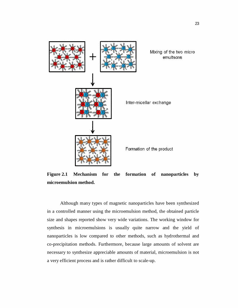
2.1.2 Reverse Micelles/Microemulsion Method
A microemulsion is a thermodynamically stable dispersion of two
immiscible liquids (water and oil) with the aid of surfactant. Small size droplets
of one liquid are stabilized in the other liquid by an interfacial film of
surfactant molecules. In the water-in-oil microemulsions, the aqueous phase
forms droplets (1-50 nm in diameter) in a continuous hydrocarbon phase.
Consequently, this system can impose kinetic and thermodynamic constraints
on particle formation, such as a nanoreactor. The surfactant-stabilized
nanoreactor provides a confinement that limits particle nucleation and growth
[43]. By mixing two identical water-in-oil emulsions containing the desired
reactants, the droplets will collide, coalesce and split and induce the formation
of precipitates (Fig. 2.1).
Adding a solvent like ethanol to the microemulsion, allows extraction of
the precipitate by filtering or centrifuging the mixture. The main advantage of
the reverse micelle or emulsion technology is better control on nanoparticles
size by varying the nature and amount of surfactant and cosurfactant, the oil
phase or the reacting conditions. The magnetite nanoparticles are formed by
reverse micelles method through oxidation of Fe2+ salts in γ-Fe2O3 and Fe3O4. The size of the magnetite particle can be controlled by the temperature and the
surfactant concentration. Variations in the temperature and concentration of
iron dodecyl sulfate Fe(DS)2 micelles allow to grow the particles of diameters
ranging from 3.7 to116 nm [44].
Page 3
23
Figure 2.1 Mechanism for the formation of nanoparticles by
microemulsion method.
Although many types of magnetic nanoparticles have been synthesized
in a controlled manner using the microemulsion method, the obtained particle
size and shapes reported show very wide variations. The working window for
synthesis in microemulsions is usually quite narrow and the yield of
nanoparticles is low compared to other methods, such as hydrothermal and
co-precipitation methods. Furthermore, because large amounts of solvent are
necessary to synthesize appreciable amounts of material, microemulsion is not
a very efficient process and is rather difficult to scale-up.
Page 4
24
2.1.3 Co-Precipitation Technique
Co-precipitation is a facile and convenient way to synthesize iron oxides
(either Fe3O4 or γ-Fe2O3) from aqueous Fe2+/Fe3+ (1:2 molar ratio) salt
solutions by the addition of a base at room temperature or at elevated
temperature. Typical overall reaction may be written as follows:
3 23 4 28 4Fe Fe OH Fe O H O
According to the thermodynamics of this reaction, complete
precipitation of Fe3O4 should be expected at a pH between 8 and 14, with a
stoichiometric ratio of 2:1 (Fe3+/Fe2+) in a non-oxidizing oxygen environment
(Fig. 2.2).
Figure 2.2 Co-Precipitation set-up for the synthesis of nanoparticles.
Page 5
25
The main advantage of the co-precipitation process is that a large
quantity of nanoparticles can be synthesized. In this process, two stages are
involved: a short burst of nucleation occurs when the concentration of the
species reaches critical supersaturation and then, there is a slow growth of the
nuclei by diffusion of the solutes into the surface of the crystal [45].
To produce monodispersed iron oxide nanoparticles, these two stages
should be separated; i.e., nucleation should be avoided during the period of
growth. Recently, significant advances have been adapted to preparing the
monodispersed magnetite nanoparticles through adding of organic additives as
stabilization and/or reducing agents. For example, Fe3O4 nanoparticles with
size range 4-10 nm were stabilized by aqueous solution of 1 wt %
polyvinlyalcohol (PVA). However, when using PVA containing 0.1 mol %
carboxyl groups as the stabilizing agent, magnetite nanoparticles in the form of
chainlike clusters precipitate [46]. This result indicates that the selection of a
proper surfactant is an important issue for the stabilization of such particles. In
general, biopolymers such as carbohydrates (dextran, chitosan, alginate,
arabinogalactan), proteins, etc., and synthetic polymers such as polyethylene
glycol (PEG), poly(vinyl alcohol) (PVA), poly(acrylic acid) (PAA),
poly(methylacrylic acid) (PMAA), poly(lactic acid), polyvinylpyrrolidone
(PVP), polyethyleneimine (PEI), AB and ABC-type block copolymers
containing the above polymers as segments are often used as precipitating
agents. Since carbohydrates are abundant in hydroxyl groups as well as
carboxylic groups (in alginate) and amino groups (in chitosan), therefore they
can firmly stick to the particle surface and effectively inhibit the growth of
crystal nuclei according to the adsorption mechanism mentioned above [47].
Although, co-precipitation is probably the most widely used method
used to obtain commercial magnetic nanoparticles for biomedical applications,
particles prepared by co-precipitation tend to be rather polydisperse and their
Page 6
26
shapes are difficult to control. Other methods have been developed to provide a
better control over the shape and size distribution of magnetic nanoparticles
such as hydrothermal method.
2.1.4 Hydrothermal Method
Hydrothermal synthesis is a wet-chemical technology of crystallizing
substance which is carried out in water under supercritical conditions, that is, at
temperatures around or higher than 200 °C under a pressure higher than
14 MPa. Under these conditions, water plays the role of a hydrolytic reactant.
The photograph of reaction container, which was used in our labarotary for
materials synthesis, is shown in Fig. 2.3.
There are two main routes for the formation of ferrites via hydrothermal
conditions: hydrolysis and oxidation or neutralization of mixed metal
hydroxides. These two reactions are very similar, except that ferrous salts are
used in the first case [48]. In this process, the reaction conditions such as the
solvent, the temperature and time are having important effects on the quality of
products [49]. The size and morphology of the nanoparticles can be tuned by
controlling the reaction time and the temperature, surfactant concentration,
nature of the solvent, precursors, and addition of seeds.
2.2 SURFACE COATING/FUNCTIONALIZATION OF IRON OXIDE
NANOPARTICLES
Stabilization of magnetic iron oxide nanoparticles for a long time
without agglomeration is crucial for several applications. Especially Fe3O4
nanoparticles are not very stable under ambient conditions and can be easily
oxidized to γ-Fe2O3.
Page 7
27
Figure 2.3 Photograph of Teflon-lined stainless steel autoclave.
Figure 2.4 Commonly used methods for coating of iron oxide
nanoparticles.
Page 8
28
The main reason for the agglomeration of magnetic iron oxide
nanoparticles is the large surface area-to-volume ratio. In the absence of any
proper surface coating, the magnetic nanoparticles try to minimize their surface
energy by forming agglomerations. The clustering process takes place through
attractive interaction between hydrophobic surface of the the nanoparticles.
Additionally, in order to expand the scope of the iron oxide nanoparticles in
biological applications surface coating and functionalization is essential
(Fig. 2.4).
2.2.1 Polymer Coating
Polymers are often employed to coat the surface of small magnetic iron
oxide nanoparticles during or after the synthesis to avoid the agglomeration. In
addition, these coating provide a means of engineering the surface of the
magnetic iron oxide nanoparticles to tailor its characteristic such as surface
charge and chemical functionality. In general, polymers can be chemically
attached or physically adsorbed on magnetic iron oxide nanoparticles to form a
single or double layer structure resulting in a repulsive (mainly as steric
repulsion) force to prevent a magnetic attraction between the iron oxide
nanoparticles. A variety of natural and synthetic polymers has been used for
coating of nanoparticles. Synthetic polymers generally the functional groups,
such as carboxylic acids, phosphates and sulfates, which can be attached on the
surface of magnetic iron oxide nanoparticles, are used. Suitable polymers for
coating include poly(pyrrole), poly(aniline), poly(alkylcyanoacrylates),
poly(methylidene malonate) and polyesters, such as poly (lactic acid),
poly(glycolic acid) and polyethylene glycol, etc.
Polyethylenimine (PEI) is a polymer and synthetic organic
macromolecules, which contains the highest density of positive charge. Many
researchers have proved PEI has high gene transfection efficiency and good
Page 9
29
biocompatibility in-vivo and in-vitro, while its limitation is that of poor
targeting. In this regard PEI, coated magnetic iron oxide nanoparticles could
be used for targeted gene delivery [50, 51]. Several groups have reported
preparation of PEI-coated magnetic particles using various methods for gene
transfections. For example, iron oxide nanoparticles are synthesized in situ
precipitation within the PEI solutions [52-54]. Kamau et al., directly mixed
maghemite dispersions with PEI solutions [55], whilst McBain and co-workers
exploited covalent bonds to attach PEI to magnetic particles [56]. The PEI
coated magnetic iron oxide nanoparticles prepared by these methods are all
capable of enhancing gene delivery.
In the recent years, researchers have been concentrating on synthesis of
protein coated magnetic iron oxide nanoparticles. Protein coated magnetic iron
oxide nanoparticles can be effectively used for biomedical applications due to
their biocompatibility and low toxicity [57, 58].
Recently, several approaches have been developed to coat magnetic iron
oxide nanoparticles by polymers and protein, including in situ coatings and
post-synthesis coatings. In situ coatings is one-pot synthesis method, have
several advantages over stepwise surface modification, including the reduced
agglomeration due to the immediate coating of the particles and less processing
procedure [59]. However, the presence of polymers or protein during the
nanocrystals nucleation and growth can have the significant impact on the
crystal structure and morphology of the nanoparticles obtained through this
process. For example, Mandeep et al., [60], found that the shape and the
structure of the nanocrystals is affected by thermal denaturation of the bovine
serum albumin (BSA) through one-pot aqueous route. Furthermore, utilizing
the polymer for coating of magnetic iron oxide surface may also reduce the
magnetic properties [61].
Page 10
30
2.2.2 Metal Coating
Another facile route to protect the iron oxide nanoparticles is formation
of core-shell (magnetic iron oxide/metal) nanocomposite. Metallic shell of
nanocomposites such as gold, silver, platinum, palladium and gadolinium not
only provide the stability to the nanoparticles in solution but also help in
binding the various biological ligands on the nanoparticle surface for various
biomedical applications. The core-shell nanoparticles have been extensively
used as a matrix and cytochemical label for the immobilization and study of
macromolecules such as drugs, proteins, enzymes, antibodies, nucleotides
tumor in hyperthermia [62-64]. Recently, several reserachers have reported on
the magnetic iron or iron oxide nanoparticles coated with Au [65], Ag [66],
Gd [67] and carbon [68]. In contrast with Au colloids, colloidal Ag
nanoparticles have several advantages. These are: (i) Ag nanoparticles exhibit a
surface plasmon band between 390 and 420 nm; that is a spectral region
distinct from that of Au (510-560 nm) [69] and (ii) the extinction coefficient of
the surface plasmon band for an Ag particle is approximately four times as
large as that for an Au particle of the same size [70].
2.2.3 Silica Coating
Silica is the most common coating material for magnetic iron oxide
nanoparticles. A silica shell not only prevent the aggregation, but can also
prevents the direct contact of the magnetic core with additional agent linked to
the surface of the silica thus prevent the unwanted interaction. For example,
the direct attachment of the luminescence materials on the surface of magnetic
nanoparticles reduces the luminescence properties. Inorder to avoid this
problem, magnetic nanoparticles were first coated by silica and then
luminescence materials were grafted on silica shell [71]. Silica coated magnetic
nanoparticles have advantages such as improved chemical stability, good
Page 11
31
biocompatability, ease in surface modification and a controlled inter particles
interaction through varying the thickness of the shell. In order to generate the
magnetic silica sphere different processes have been explored such as Stöber
process, sol-gel process and aerosol pyrolysis. Stöber process is a well known
process, in which silica is formed in situ through the hydrolysis and
condensation of a sol-gel precursor, such as tetraethyl orthosilicate (TEOS)
[72]. The thickness of the silica shell can be tuned by varying the concentration
of ammonium and the ratio of TEOS to H2O. Furthermore, silica contains free
silanol groups that can be subsequently reacted with additional appropriate
functional groups through relevant silanization reactions [73].
In the recent years, researchers are concentrating on development of
silica encapsulation of nanoparticles with dual functionalities such as
fluorescence and magnetism [74]. Such materials can be physically
manipulated by application of an external magnetic field and simultaneously
optically probed by monitoring their fluorescence in real time. Further, it has
recently been proposed that such nanocrystals could themselves be used as both
magnetic and optical subunits in these silica core-shell systems. Specifically,
superparamagnetic iron oxide nanoparticles have been used for magnetism
based protein harvesting, magnetic resonance imaging (MRI), hyperthermia
treatment, bioseparation and magnetic sensing of biomolecules [75], while
semiconducting quantum dots (QDs) or fluorescent dyes have been used in
fluorescence-based biolabeling and imaging applications at the subcellular
level [76].
The fluorescent nanoparticles for optical imaging can be divided into
two major categories: Dye doped nanoparticles and quantum dots [12].
Usually, dye molecules suffer from photobleaching and quenching due to
interactions with solvent molecules and reactive species such as oxygen or ions
Page 12
32
dissolved in solution when they are exposed to a variety of harsh environments
[77]. Whereas, QDs are more photochemically stable and have narrower,
tunable emission spectra than fluorescent dye molecules [78-80]. However, to
overcome the toxicity (generally related to heavy metal ions such as Pb2+ or
Cd2+) associated with quantum dots remains challenge, which limits the
adoption of multimodal probes containing QDs, photo-oxidation and difficult
surface conjugation chemistry associated with QDs limiting their applications
[81]. A very promising direction is the use of heavy-metal-free like carbon-
based fluorescent materials, including carbon nanoparticles (CNPs) and carbon
quantum dots (CDs) have received particular attention. Compared with
conventional QDs, carbon based fluorescent materials are superior in chemical
stability and biocompatibility [82].
Several methods have been developed for synthesis of magnetic and
luminescent composite silica microspheres containing both magnetic iron oxide
nanoparticles and luminescnet QDs such as inverse suspension method,
simultaneous coating of the silica shell on magnetic iron oxide nanoparticles
and luminescent QDs. However, the drawback of this method is polydispersity
of the nanoparticles within the silica spheres. Recently, magnetic and
luminescent silica spheres were synthesised by using silica coated magnetic
iron oxide nanoparticles, followed by layer-by-layer assembly of QDs on
magnetic silica sphere through electrostatic interaction, which were finally
coated by silica shell [83]. However, polydispersity of nanoparticles was not
calculated. Monodispersed state of the nanoparticles is very essential to retain
both magnetic and luminescence properties. Insin et al., have developed sol-gel
method to synthesis the magnetic and luminescent silica sphere [84].
Page 13
33
2.3 CHARACTERIZATION TECHNIQUES FOR IRON OXIDE
NANOPARTICLES
2.3.1 X-Ray Diffraction
X-ray diffraction (XRD) is a method used to characterize the crystal
structure and analyse the parrticular phase of the material. XRD is basically
used to identify unknown substances, by comparing diffraction data with a
database maintained by the International Centre for Diffraction Data (ICDD).
These techniques are based on collecting the scattered intensity of an X-ray
beam hitting a sample as a function of incident and scattered angle, polarization
and wavelength or energy. The peak intensity in XRD result can be used to
quantify the proportion of iron oxide forms in a mixture by comparing
experimental peak and a reference peak intensity. The crystal size also can be
calculated from line broadening from the XRD pattern using the Scherrer’s
equation. The crystalline structure of the products were identified using
Panalytical X'pert Pro diffractometer with CuKα radiation (λ = 0.15417 nm).
Approximately 10 mg of sample was placed onto a silicon zero-reflectance disc
adhered to an aluminum sample plate. In the present work, XRD data were
collected with 2θ ranging from 10 to 80 degree at a rate of 2 degree per minute.
2.3.2. Scanning Electron Microscopy
Scanning electron microscopy (SEM) is a technique which provides
high resolution three dimensional morphological and topographical information
of the solid surface. When the high intensity electron beam hits a point on the
sample, numerous collisions between the electron from the beam and atoms in
the sample will occur, which cause it to emit secondary electron. These
secondary electrons have relatively low energy and can easily attach by the
Page 14
34
detector. The detector counts the number of electrons emitted from the sample
and resulting pattern produces a three dimensional image on the screen of a
cathode ray tube. In the present work, FESEM-Hitachi S4800, field emission
SEM was used for higher resolution. Samples were prepared by mounting them
to a piece of carbon tape on a designated sample holder and dried for at least 24
h in a desiccator. The samples could be mounted parallel or perpendicular to
the electron beam.
2.3.3 Transmission Electron Microscopy
Transmission electron microscopy (TEM) is a technique that is used to
characterize the morphology and size of materials such as nanoparticles. These
instruments are used because of the limited image resolution in light
microscopes imposed by the wavelength of visible light. Electrons have wave
like characteristics, with a wavelength substantially less than visible light.
Since electrons are smaller than atoms, TEM is capable of resolving atomic
level detail. Samples are prepared for TEM imaging by inserting a TEM grid
(copper coated) into dry or wet powder (usually dried over-night) using
tweezers to hold the grid. The sample grid is then lightly tapped to remove any
excess particles and the grid is placed in the TEM for imaging. This procedure
can be used to characterize the coated and uncoated magnetic particles.
A JEM 3010 (JEOL) operated at 200 kV was utilized to view particle
size and shape of nanoparticles. In the present work, the samples for TEM
measurements were prepared by weighing approximately 0.01 g of synthesized
samples, dispersed into 5 ml methanol under sonication. The suspension was
then dropped on a copper coated TEM grid and kept in desiccator over-night to
dry. Size analysis from the transmission electron micrographs was performed
using image processing software ImageJ.
Page 15
35
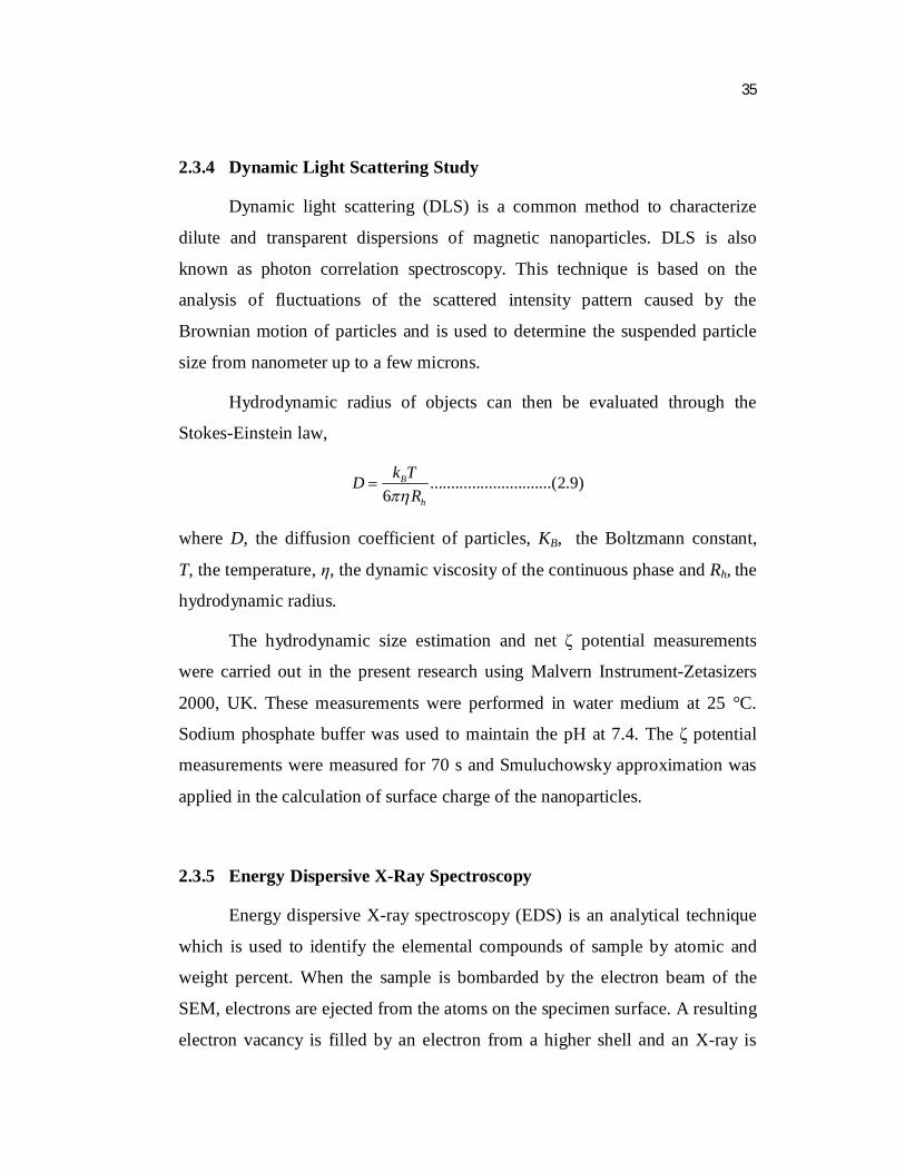
2.3.4 Dynamic Light Scattering Study
Dynamic light scattering (DLS) is a common method to characterize
dilute and transparent dispersions of magnetic nanoparticles. DLS is also
known as photon correlation spectroscopy. This technique is based on the
analysis of fluctuations of the scattered intensity pattern caused by the
Brownian motion of particles and is used to determine the suspended particle
size from nanometer up to a few microns.
Hydrodynamic radius of objects can then be evaluated through the
Stokes-Einstein law,
.............................(2.9)6
B
h
k TDR
where D, the diffusion coefficient of particles, KB, the Boltzmann constant,
T, the temperature, η, the dynamic viscosity of the continuous phase and Rh, the
hydrodynamic radius.
The hydrodynamic size estimation and net ζ potential measurements
were carried out in the present research using Malvern Instrument-Zetasizers
2000, UK. These measurements were performed in water medium at 25 °C.
Sodium phosphate buffer was used to maintain the pH at 7.4. The ζ potential
measurements were measured for 70 s and Smuluchowsky approximation was
applied in the calculation of surface charge of the nanoparticles.
2.3.5 Energy Dispersive X-Ray Spectroscopy
Energy dispersive X-ray spectroscopy (EDS) is an analytical technique
which is used to identify the elemental compounds of sample by atomic and
weight percent. When the sample is bombarded by the electron beam of the
SEM, electrons are ejected from the atoms on the specimen surface. A resulting
electron vacancy is filled by an electron from a higher shell and an X-ray is
Page 16
36
emitted to balance the energy difference between the two electrons. The X-ray
detector measures the number of emitted X-rays versus their energy. The
energy of the X-ray is characteristic of the element from which the X-ray was
emitted. A spectrum of the energy versus relative counts of the detected X-ray
is obtained and evaluated for qualitative and quantitative determinations of the
elements present.
2.3.6 Fourier Transform Infrared Spectroscopy
Fourier transform infrared spectroscopy (FTIR) is a technique which is
used to determine the chemical functional groups in the sample. In infrared
spectroscopy, IR radiation is passed through a sample. Some of the infrared
radiation is absorbed by the sample and some of it is passed through
(transmitted). The resulting spectrum represents the molecular absorption and
transmission, creating a molecular fingerprint of the sample. Like a fingerprint
no two unique molecular structures produce the same infrared spectrum. This
makes infrared spectroscopy useful for several types of analyses. For infrared
spectroscopy, solid samples were analyzed on Perkin-Elmer 580B IR
spectrophotometer using KBr pellet technique between 4000 and 500 cm-1 for
16 scans at a resolution of 4 cm-1.
2.3.7 Raman Spectroscopy
Raman spectroscopy is important technique to identify organic
molecules and phase of the minerals. It is similar to FTIR spectroscopy but it
has several distinct advantages. For example, it can be used to study solids,
liquids, powders, gels, slurries and aqueous solutions. This technique is based
on inelastic scattering of monochromatic light, usually from a laser source.
Page 17
37
Inelastic scattering is the frequency of photons of monochromatic light
changes upon interaction with a sample. Photons of the laser light are absorbed
by the sample and then reemitted. Frequency of the reemitted photons is shifted
up or down compared to original monochromatic frequency, which is called the
Raman effect. This shift provides information about vibrational, rotational and
other low frequency transitions in molecules.
The MicroRaman measurement was carried out with an HR 800
(Jobin-Yvon) Raman microscope equipped with 1800 grooves/mm holographic
grating. He-Ne laser of 633 nm was used as an excitation source. The laser spot
size focused on the surface was approximately 0.33 μm and the depth
resolution is 0.5 μm. The output of the filtered He-Ne laser was 20 mW.
2.3.8 UV-Visible Spectroscopy
Ultraviolet-visible (UV-Vis) spectroscopy is used to obtain the
absorbance spectra of a compound in solution or as a solid. Since the
absorption of ultraviolet or visible radiation by a molecule leads transition from
ground state to exited state of the molecule, it is also often called as electronic
spectroscopy. The absorbance data from the UV-Vis measurement can be
related to the concentration of the sample by Beer’s Law.
UV-Vis absorption spectra values were recorded using Perkin Elmer
Lambda 5 UV-visible spectrophotometer in the present research. Information
collected from the scans were stored and analyzed by the UV Probe Version
2.31 software. Scans were performed in the UV and visible range, 260-800 nm,
with a 3 nm slit size. Samples were prepared by dispersing rare earth
nanoparticles in tetrahydrofuran followed by sonication for 15 minutes. An
appropriate polymer was then added to the solution, sonicated and stirred until
Page 18
38
completely dissolved. Measurements were carried out in a quartz cuvette with a
10 mm path length at room temperature.
2.3.9 Photoluminescence Spectroscopy
Photoluminescence (PL) is a non-destructive optical technique used for
the characterization, investigation and detection of point defects or for
measuring the band-gaps of materials. PL involves the creation of electron-hole
pairs by incident radiation (photo-excitation) and subsequent radiative
recombination photon emission. Photo-excitation causes electrons within a
material to move into permissible excited states. When these electrons return to
their equilibrium states, the excess energy is released and may give rise to
emission of light (a radiative process) or may not (a non-radiative process). The
energy of the emitted light (photoluminescence) relates to the difference in
energy levels between the two electron states involved in the transition between
the excited state and the equilibrium state. The quantity of the emitted light is
related to the relative contribution of the radiative process.
Photoluminescence proceeds via following three steps [85]:
1) Excitation: Excitation of electrons from lower energy state to higher
energy state by absorption of energy from external sources, such as
lasers, arc-discharge lamps and xenon lamp and in this process
electron-hole pairs are created.
2) Thermalization: Excited pairs relax towards quasi-thermal equilibrium
distributions.
3) Recombination: The energy can subsequently be released, in the form of
a lower energy photon, when the electron falls back to the original
ground state. This process can occur radiatively or non-radiatively.
Page 19
39
Room temperature photoluminescence spectra were recorded using
Horiba Jobin Yvon photoluminescence system comprising of Xenon lamp as
excitation source, Gemini 180 as excitation monochromator, iHR 320 as
emission monochromator and liquid Nitrogen cooled (150 K) CCD detector.
Symphony software was used to run the system. The excitation scans were
carried out in a range from 200 to 450 nm, while the emissions scans were
mostly in the visible spectrum, from 400 to 800 nm. PL spectrum was recorded
for liquid samples. Colloidal nanoparticles were placed into the quartz cuvette
with a 10 mm path length. Standard photoluminescence scan were done at 50
nm/min., using 3 nm slit width for both excitation and emission band passes.
2.3.10 Vibrating Sample Magnetometer
A vibrating sample magnetometer (VSM) was used to measure the
magnetic properties of materials. A sample was placed inside a uniform
magnetic field to magnetize the sample. The sample was then physically
vibrated sinusoidally, typically through the use of a piezoelectric material.
Commercial systems use linear attenuators of some form and historically the
development of these systems was done using modified audio speaker, though
this approach was dropped due to the interference through the in-phase
magnetic noise produced, as the magnetic flux through a nearby pickup coil
varies sinusoidally. The induced voltage in the pickup coil is proportional to
the sample’s magnetic moment but does not depend on strength of applied
magnetic field. In a typical setup, the induced voltage is measured through the
use of a lock-in amplifier using the piezoelectric signal as its reference signal.
By measuring the field of an external electromagnet, it is possible to obtain the
hysteresis curve of materials.
The magnetization measurements were performed by VSM JDM-13
vibrating sample magnetometer with applied magnetic field in the range of
Page 20
40
-15 to 15 kOe. The temperature dependence of the magnetization was
monitored by warming the sample with an applied field of 100 Oe. The shape
of the sample holder was cylindrical, with a diameter of 5.5 mm and a height of
2.7 mm.