42
S e r v i c e M a n u a l Synthesized RNet ™ VHF JSLM Telemetry Link Part Number: 001-2010-XXX
S e r v i c e M a n u a l
Synthesized RNet™ VHF JSLM Telemetry Link
Part Number: 001-2010-XXX
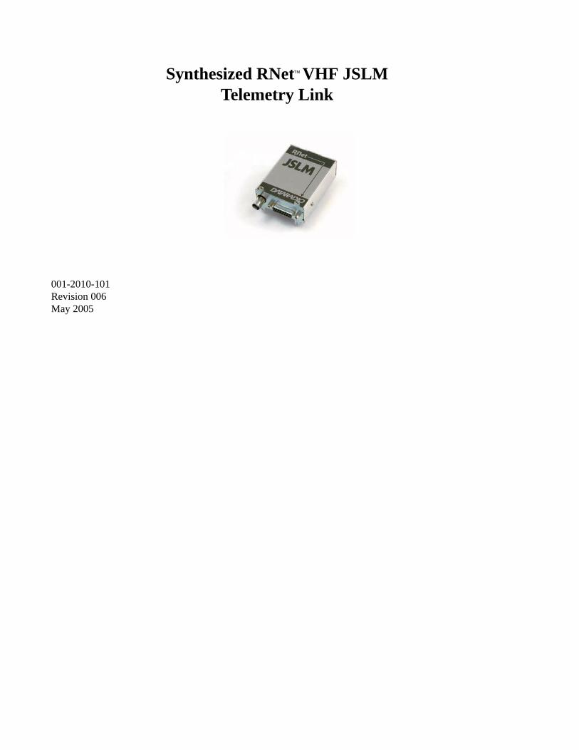
001-2010-101 Revision 006 May 2005
Synthesized RNet™ VHF JSLMTelemetry Link
About DataradioDataradio is a leading designer and manufacturer of advanced wireless data products and systems for mission critical applications. Our products are found at the heart of mobile data and SCADA networks around the world. With over 20 years dedicated to data technology and innovation, Dataradio is the premier source for wireless data solutions. Our products include mobile data products, telemetry devices, integrated wireless modems for fixed point-to-point and point to multi-point applications, and OEMs. Our product line is one of the broadest in the industry covering the most often-used frequency bands.
Product WarrantyThe manufacturer's warranty statement for this product is available in Appendix section of this manual.
www.dataradio.comDataradio provides product brochures, case studies software downloads and product information on our website.
Every effort is taken to provide accurate, timely product information in this technical manual. Product updates may result in differences between the information provided herein and the product shipped. The information in this document is subject to change without notice.
Dataradio is a registerd trademark of Dataradio, Inc.
1
Part No. 001-2010-002
TABLE OF CONTENTS
1 GENERAL INFORMATION
1.1 SCOPE OF MANUAL . . . . . . . . . . . . . . . . . . . . . . . . . . . . . . . . . . . . . . . . . . . . . . . . . . . . . . . . . . . . . . . 1-11.2 EQUIPMENT DESCRIPTION . . . . . . . . . . . . . . . . . . . . . . . . . . . . . . . . . . . . . . . . . . . . . . . . . . . . . . . . . 1-1
GENERAL. . . . . . . . . . . . . . . . . . . . . . . . . . . . . . . . . . . . . . . . . . . . . . . . . . . . . . . . . . . . . . . . . . . . . . . . 1-1VHF RNet JSLM RADIO/LOADER . . . . . . . . . . . . . . . . . . . . . . . . . . . . . . . . . . . . . . . . . . . . . . . . . . . . . 1-1
1.3 TRANSCEIVER IDENTIFICATION . . . . . . . . . . . . . . . . . . . . . . . . . . . . . . . . . . . . . . . . . . . . . . . . . . . . 1-11.4 PART NUMBER BREAKDOWN . . . . . . . . . . . . . . . . . . . . . . . . . . . . . . . . . . . . . . . . . . . . . . . . . . . . . . 1-11.5 ACCESSORIES . . . . . . . . . . . . . . . . . . . . . . . . . . . . . . . . . . . . . . . . . . . . . . . . . . . . . . . . . . . . . . . . . . . 1-21.6 TECHNICAL SERVICE . . . . . . . . . . . . . . . . . . . . . . . . . . . . . . . . . . . . . . . . . . . . . . . . . . . . . . . . . . . . . 1-21.7 PRODUCT WARRANTY . . . . . . . . . . . . . . . . . . . . . . . . . . . . . . . . . . . . . . . . . . . . . . . . . . . . . . . . . . . . 1-31.8 FACTORY REPAIR . . . . . . . . . . . . . . . . . . . . . . . . . . . . . . . . . . . . . . . . . . . . . . . . . . . . . . . . . . . . . . . . 1-3
GENERAL SPECIFICATIONS . . . . . . . . . . . . . . . . . . . . . . . . . . . . . . . . . . . . . . . . . . . . . . . . . . . . . . . . 1-4
2 INSTALLATION
2.1 PRE-INSTALLATION CHECKS . . . . . . . . . . . . . . . . . . . . . . . . . . . . . . . . . . . . . . . . . . . . . . . . . . . . . . . 2-12.2 INTERFACING WITH THE VHF RNet JSLM . . . . . . . . . . . . . . . . . . . . . . . . . . . . . . . . . . . . . . . . . . . . . 2-1
INPUT POWER SUPPLY REQUIREMENTS . . . . . . . . . . . . . . . . . . . . . . . . . . . . . . . . . . . . . . . . . . . . . 2-1ANTENNA AND VSWR . . . . . . . . . . . . . . . . . . . . . . . . . . . . . . . . . . . . . . . . . . . . . . . . . . . . . . . . . . . . . 2-2RECEIVER SELECTIVITY ADJUSTMENT . . . . . . . . . . . . . . . . . . . . . . . . . . . . . . . . . . . . . . . . . . . . . . 2-2CONNECTOR J204 USER INTERFACE . . . . . . . . . . . . . . . . . . . . . . . . . . . . . . . . . . . . . . . . . . . . . . . . 2-2GENERAL PINOUT DESCRIPTION. . . . . . . . . . . . . . . . . . . . . . . . . . . . . . . . . . . . . . . . . . . . . . . . . . . . 2-2
3 PROGRAMMING
3.1 INTRODUCTION . . . . . . . . . . . . . . . . . . . . . . . . . . . . . . . . . . . . . . . . . . . . . . . . . . . . . . . . . . . . . . . . . . 3-1GENERAL. . . . . . . . . . . . . . . . . . . . . . . . . . . . . . . . . . . . . . . . . . . . . . . . . . . . . . . . . . . . . . . . . . . . . . . . 3-1
3.2 RNet JSLM FIELD PROGRAMMING SOFTWARE . . . . . . . . . . . . . . . . . . . . . . . . . . . . . . . . . . . . . . . . 3-1INTRODUCTION . . . . . . . . . . . . . . . . . . . . . . . . . . . . . . . . . . . . . . . . . . . . . . . . . . . . . . . . . . . . . . . . . . 3-1SETUP MODEM/RADIO PARAMETERS . . . . . . . . . . . . . . . . . . . . . . . . . . . . . . . . . . . . . . . . . . . . . . . . 3-2SETTINGS TAB . . . . . . . . . . . . . . . . . . . . . . . . . . . . . . . . . . . . . . . . . . . . . . . . . . . . . . . . . . . . . . . . . . . 3-2RADIO TAB. . . . . . . . . . . . . . . . . . . . . . . . . . . . . . . . . . . . . . . . . . . . . . . . . . . . . . . . . . . . . . . . . . . . . . . 3-4FREQUENCIES TAB . . . . . . . . . . . . . . . . . . . . . . . . . . . . . . . . . . . . . . . . . . . . . . . . . . . . . . . . . . . . . . . 3-6VERSION REQUEST . . . . . . . . . . . . . . . . . . . . . . . . . . . . . . . . . . . . . . . . . . . . . . . . . . . . . . . . . . . . . . . 3-7READ/WRITE PROGRAMMABLE SETTINGS. . . . . . . . . . . . . . . . . . . . . . . . . . . . . . . . . . . . . . . . . . . . 3-7PORT SETTINGS . . . . . . . . . . . . . . . . . . . . . . . . . . . . . . . . . . . . . . . . . . . . . . . . . . . . . . . . . . . . . . . . . . 3-7PORT STATISTICS . . . . . . . . . . . . . . . . . . . . . . . . . . . . . . . . . . . . . . . . . . . . . . . . . . . . . . . . . . . . . . . 3-10USER TEST . . . . . . . . . . . . . . . . . . . . . . . . . . . . . . . . . . . . . . . . . . . . . . . . . . . . . . . . . . . . . . . . . . . . . 3-11ASCII/HEX TERMINAL . . . . . . . . . . . . . . . . . . . . . . . . . . . . . . . . . . . . . . . . . . . . . . . . . . . . . . . . . . . . . 3-13
3.3 JSLM FIELD PROGRAMMING SOFTWARE HELP FILES . . . . . . . . . . . . . . . . . . . . . . . . . . . . . . . . 3-14
4 ALIGNMENT AND TROUBLESHOOTING
4.1 GENERAL . . . . . . . . . . . . . . . . . . . . . . . . . . . . . . . . . . . . . . . . . . . . . . . . . . . . . . . . . . . . . . . . . . . . . . . 4-1PERIODIC CHECKS. . . . . . . . . . . . . . . . . . . . . . . . . . . . . . . . . . . . . . . . . . . . . . . . . . . . . . . . . . . . . . . . 4-1SERVICING . . . . . . . . . . . . . . . . . . . . . . . . . . . . . . . . . . . . . . . . . . . . . . . . . . . . . . . . . . . . . . . . . . . . . . 4-1
5.2 PERFORMANCE CHECKS . . . . . . . . . . . . . . . . . . . . . . . . . . . . . . . . . . . . . . . . . . . . . . . . . . . . . . . . . . 4-1FRONT-END TUNING . . . . . . . . . . . . . . . . . . . . . . . . . . . . . . . . . . . . . . . . . . . . . . . . . . . . . . . . . . . . . . 4-1CHANNEL FREQUENCY . . . . . . . . . . . . . . . . . . . . . . . . . . . . . . . . . . . . . . . . . . . . . . . . . . . . . . . . . . . . 4-1
TABLE OF CONTENTS
2Part No. 001-2010-002
RF OUTPUT POWER. . . . . . . . . . . . . . . . . . . . . . . . . . . . . . . . . . . . . . . . . . . . . . . . . . . . . . . . . . . . . . . 4-2TRANSMIT DEVIATION LIMITING. . . . . . . . . . . . . . . . . . . . . . . . . . . . . . . . . . . . . . . . . . . . . . . . . . . . . 4-2TRANSMIT DEVIATION . . . . . . . . . . . . . . . . . . . . . . . . . . . . . . . . . . . . . . . . . . . . . . . . . . . . . . . . . . . . . 4-2RECEIVE AUDIO LEVEL . . . . . . . . . . . . . . . . . . . . . . . . . . . . . . . . . . . . . . . . . . . . . . . . . . . . . . . . . . . . 4-2
5.3 TROUBLESHOOTING . . . . . . . . . . . . . . . . . . . . . . . . . . . . . . . . . . . . . . . . . . . . . . . . . . . . . . . . . . . . . . 4-3
APPENDIX A: TECHNICAL SUPPORT APPLICATION NOTE. . . . . . . . . . . . . . . . . . . . . . . . . . . . . . . . . . . . A-1APPENDIX B: DATA TELEMETRY PRODUCT WARRANTY. . . . . . . . . . . . . . . . . . . . . . . . . . . . . . . . . . . . . B-1APPENDIX C: MIC MARK . . . . . . . . . . . . . . . . . . . . . . . . . . . . . . . . . . . . . . . . . . . . . . . . . . . . . . . . . . . . . . . . C-1
LIST OF FIGURES
1-1 VHF RNet JSLM WITH MOUNTING BRACKET KIT . . . . . . . . . . . . . . . . . . . . . . . . . . . . . . . . . . . . . . . 1-21-2 TRANSMIT DUTY CYCLE . . . . . . . . . . . . . . . . . . . . . . . . . . . . . . . . . . . . . . . . . . . . . . . . . . . . . . . . . . . 1-61-3 TYPICAL OUTPUT POWER VS SUPPLY VOLTAGE . . . . . . . . . . . . . . . . . . . . . . . . . . . . . . . . . . . . . . 1-7
2-1 VHF RNET JSLM TRANSCEIVER . . . . . . . . . . . . . . . . . . . . . . . . . . . . . . . . . . . . . . . . . . . . . . . . . . . . . 2-12-2 RNET JSLM ACCESSORY INTERCONNECT POWER CABLE . . . . . . . . . . . . . . . . . . . . . . . . . . . . . . 2-4
3-1 RNet JSLM FIELD PROGRAMMING SOFTWARE SETUP . . . . . . . . . . . . . . . . . . . . . . . . . . . . . . . . . . 3-13-2 RNet JSLM FIELD PROGRAMMING SOFTWARE START-UP SCREEN . . . . . . . . . . . . . . . . . . . . . . . 3-23-3 SETUP RNet JSLM PARAMETERS - SETTINGS TAB . . . . . . . . . . . . . . . . . . . . . . . . . . . . . . . . . . . . . 3-33-4 SETUP RADIO PARAMETERS - RADIO TAB . . . . . . . . . . . . . . . . . . . . . . . . . . . . . . . . . . . . . . . . . . . . 3-53-5 SETUP RADIO PARAMETERS - FREQUENCIES TAB. . . . . . . . . . . . . . . . . . . . . . . . . . . . . . . . . . . . . 3-63-6 SERIAL PC PORT SETTINGS SCREEN . . . . . . . . . . . . . . . . . . . . . . . . . . . . . . . . . . . . . . . . . . . . . . . . 3-83-7 SERIAL PC PORT STATISTICS SCREEN . . . . . . . . . . . . . . . . . . . . . . . . . . . . . . . . . . . . . . . . . . . . . 3-103-8 RNet JSLM USER TEST SCREEN . . . . . . . . . . . . . . . . . . . . . . . . . . . . . . . . . . . . . . . . . . . . . . . . . . . 3-123-9 ASCII TERMINAL SCREEN . . . . . . . . . . . . . . . . . . . . . . . . . . . . . . . . . . . . . . . . . . . . . . . . . . . . . . . . . 3-133-10 RNet JSLM FIELD PROGRAMMING HELP SCREEN . . . . . . . . . . . . . . . . . . . . . . . . . . . . . . . . . . . . . 3-14
4-1 RNet JSLM RF BOARD ADJUSTMENT POINTS . . . . . . . . . . . . . . . . . . . . . . . . . . . . . . . . . . . . . . . . . 4-44-2 RNet JSLM LOADER BOARD ADJUSTMENT POINTS . . . . . . . . . . . . . . . . . . . . . . . . . . . . . . . . . . . . 4-4
LIST OF TABLES
1-1 VHF RNET JSLM ACCESSORIES. . . . . . . . . . . . . . . . . . . . . . . . . . . . . . . . . . . . . . . . . . . . . . . . . . . . . 1-21-2 RSSI VOLTAGES VS RF INPUT LEVEL @ J204, PIN 11 . . . . . . . . . . . . . . . . . . . . . . . . . . . . . . . . . . . 1-6
2-1 CHANNEL SELECT TABLE . . . . . . . . . . . . . . . . . . . . . . . . . . . . . . . . . . . . . . . . . . . . . . . . . . . . . . . . . . 2-2
3-1 COMMUNICATION MODES. . . . . . . . . . . . . . . . . . . . . . . . . . . . . . . . . . . . . . . . . . . . . . . . . . . . . . . . . . 3-9
TABLE OF CONTENTS
3Part No. 001-2010-002
REVISION HISTORY
Revision 006May 2005
Updated Transceiver Identification labeling information Section 1. Updated User Cable information, Section 2. Added MIC Mark information to Appendix C.
Revision 005February 2005
Update hard copy version to new cover format.
Revision 004October 2002
Added information to include board revisions for product features available in newer products.
Revision 003August 2002
Updated manual to reflect changes to product due to obsolescence.
Revision 002November 2001
Updated manual to CD-Rom/Hard Copy versions.
Revision 001April 1999
Updated manual to revsion 001 - parts changes
Revision 000April 1998
Manual release.
1-1 Part No. 001-2010-101
SECTION 1
GENERAL INFORMATION
1.1 SCOPE OF MANUAL
This manual contains operating instructions and alignment information for the Dataradio COR Ltd. (DRL) VHF RNet TM JSLM Transceiver.
1.2 EQUIPMENT DESCRIPTION
1.2.1 GENERAL
The Dataradio VHF RNet JSLM is a synthesized transceiver (transmitter and receiver) which operates in the132-174 MHz VHF frequency range. Transmitter power output is 2 watts at 7.5 Vdc and 5 watts nominal at 11.25Vdc. The mode of operation is simplex or half duplex. The JSLM Transceiver has a frequency stability of ± 2.5PPM.
1.2.2 VHF JSLM RADIO/LOADER
The VHF RNet JSLM includes the 8-channel Loader Board which performs synthesizer loading. The Loader Board provides transmit/receive audio conditioning and gating, carrier detect, RSSI buffering, and synthesizer loading. The gating circuits allow the type of audio response to be selected; flat, pre-emphasis or de-emphasis.
This board is programmed using a personal computer (PC) and RNet JSLM Field Programming Software. Field Programming Software is Windows® based sofware and requires a Windows® 95 or newer operating system. Programming information is stored by an EEPROM on the Loader Board.
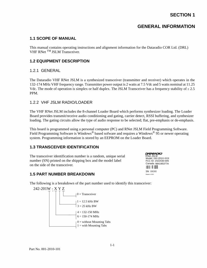
1.3 TRANSCEIVER IDENTIFICATION
The transceiver identification number is a random, unique serial number (SN) printed on the shipping box and the model label on the side of the transceiver.
1.5 PART NUMBER BREAKDOWN
The following is a breakdown of the part number used to identify this transceiver:242-201W - X Y Z
0 = Transceiver
1 = 12.5 kHz BW 3 = 25 kHz BW
4 = 132-150 MHz6 = 150-174 MHz
0 = without Mounting Tabs1 = with Mounting Tabs
RNet JSLMModel: 242-201X-XXXFCC ID: 2422430-005Canada
SN XXXXMade in USA
: 984195377A
1-2Part No. 001-2010-101
1.6 ACCESSORIES
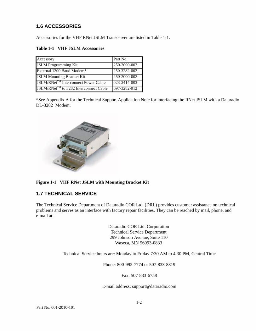
Accessories for the VHF RNet JSLM Transceiver are listed in Table 1-1.
Table 1-1 VHF JSLM Accessories
*See Appendix A for the Technical Support Application Note for interfacing the RNet JSLM with a DataradioDL-3282 Modem.
Figure 1-1 VHF RNet JSLM with Mounting Bracket Kit
1.7 TECHNICAL SERVICE
The Technical Service Department of Dataradio COR Ltd. (DRL) provides customer assistance on technical problems and serves as an interface with factory repair facilities. They can be reached by mail, phone, and e-mail at:
Dataradio COR Ltd. CorporationTechnical Service Department299 Johnson Avenue, Suite 110
Waseca, MN 56093-0833
Technical Service hours are: Monday to Friday 7:30 AM to 4:30 PM, Central Time
Phone: 800-992-7774 or 507-833-8819
Fax: 507-833-6758
E-mail address: [email protected]
Accessory Part No.JSLM Programming Kit 250-2000-003External 1200 Baud Modem* 250-3282-002JSLM Mounting Bracket Kit 250-2000-002JSLM/RNet™ Interconnect Power Cable 023-3414-003JSLM/RNet™ to 3282 Interconnect Cable 697-3282-012
1-3Part No. 001-2010-101
1.8 PRODUCT WARRANTY
The warranty statement for the VHF RNet JSLM is available in the Appendix section of this manual.
1.9 FACTORY REPAIR
This product is not field serviceable, except by the replacement of complete units. Specialized equipment and training is required to repair logic boards and radio modules. Contact Technical Services before returning equipment. A technician may suggest a solution eliminating the need to return equipment.
A Return Material Authorization (RMA) is required when returning equipment to Dataradio for repair. Contact the Dataradio at 800-992-7774, extension 6707 to request an RMA number. Be prepared to give the equipment model and serial number, your account number (if known), and billing and shipping addresses. Include the RMA number, a complete description of the problem, and the name and phone number of a contact person with the returned units. This information is important. The technician may have questions that need to be answered to identify the problem and repair the equipment. The RMA number helps locate your equipment in the repair lab if there is a need to contact Dataradio concerning the equipment. Units sent in for repair will be returned to the customer re-tuned to the current Dataradio Test and Tune Procedure and will conform to all specifications noted in this section
Customers are responsible for shipping charges (to Dataradio) for returned units in warranty. Units in warranty are repaired free of charge unless there is evidence of abuse or damage beyond the terms of the warranty. Dataradio covers return shipping costs for equipment repaired while under warranty.
Units out of warranty are subject to repair service charges. Customers are responsible for shipping charges (to and from Dataradio) on units out of warranty. Return shipping instructions are the responsibility of the customer.
1-4Part No. 001-2010-101
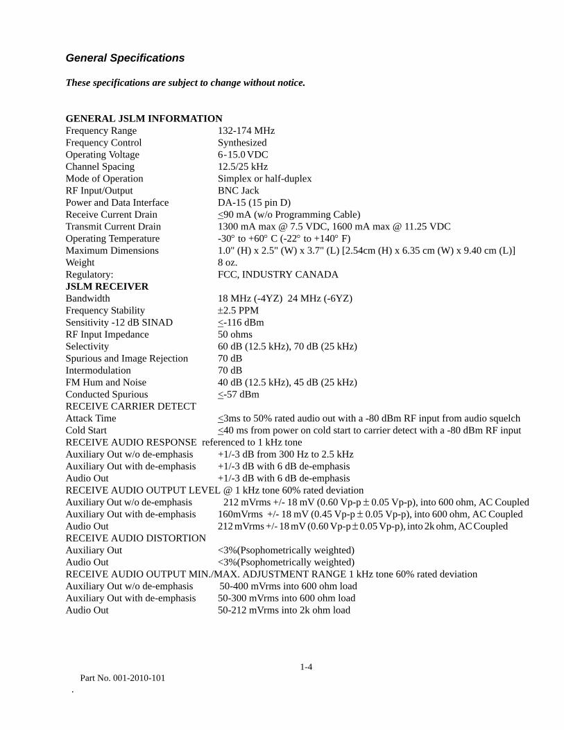
General Specifications
These specifications are subject to change without notice.
GENERAL JSLM INFORMATION Frequency Range 132-174 MHz Frequency Control SynthesizedOperating Voltage 6 - 15.0 VDC Channel Spacing 12.5/25 kHzMode of Operation Simplex or half-duplexRF Input/Output BNC Jack Power and Data Interface DA-15 (15 pin D) Receive Current Drain <90 mA (w/o Programming Cable)Transmit Current Drain 1300 mA max @ 7.5 VDC, 1600 mA max @ 11.25 VDCOperating Temperature -30° to +60° C (-22° to +140° F)Maximum Dimensions 1.0" (H) x 2.5" (W) x 3.7" (L) [2.54cm (H) x 6.35 cm (W) x 9.40 cm (L)]Weight 8 oz.Regulatory: FCC, INDUSTRY CANADA JSLM RECEIVERBandwidth 18 MHz (-4YZ) 24 MHz (-6YZ)Frequency Stability ±2.5 PPMSensitivity -12 dB SINAD <-116 dBmRF Input Impedance 50 ohmsSelectivity 60 dB (12.5 kHz), 70 dB (25 kHz)Spurious and Image Rejection 70 dB Intermodulation 70 dBFM Hum and Noise 40 dB (12.5 kHz), 45 dB (25 kHz) Conducted Spurious <-57 dBmRECEIVE CARRIER DETECT Attack Time <3ms to 50% rated audio out with a -80 dBm RF input from audio squelchCold Start <40 ms from power on cold start to carrier detect with a -80 dBm RF inputRECEIVE AUDIO RESPONSE referenced to 1 kHz tone Auxiliary Out w/o de-emphasis +1/-3 dB from 300 Hz to 2.5 kHzAuxiliary Out with de-emphasis +1/-3 dB with 6 dB de-emphasisAudio Out +1/-3 dB with 6 dB de-emphasisRECEIVE AUDIO OUTPUT LEVEL @ 1 kHz tone 60% rated deviation Auxiliary Out w/o de-emphasis 212 mVrms +/- 18 mV (0.60 Vp-p ± 0.05 Vp-p), into 600 ohm, AC Coupled Auxiliary Out with de-emphasis 160mVrms +/- 18 mV (0.45 Vp-p ± 0.05 Vp-p), into 600 ohm, AC Coupled Audio Out 212 mVrms +/- 18 mV (0.60 Vp-p ± 0.05 Vp-p), into 2k ohm, AC Coupled RECEIVE AUDIO DISTORTION Auxiliary Out <3%(Psophometrically weighted) Audio Out <3%(Psophometrically weighted)RECEIVE AUDIO OUTPUT MIN./MAX. ADJUSTMENT RANGE 1 kHz tone 60% rated deviation Auxiliary Out w/o de-emphasis 50-400 mVrms into 600 ohm loadAuxiliary Out with de-emphasis 50-300 mVrms into 600 ohm loadAudio Out 50-212 mVrms into 2k ohm load
.
1-5Part No. 001-2010-101
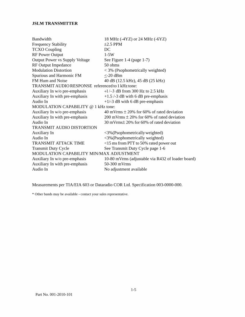
JSLM TRANSMITTER
Bandwidth 18 MHz (-4YZ) or 24 MHz (-6YZ)Frequency Stability ±2.5 PPMTCXO Coupling DCRF Power Output 1-5WOutput Power vs Supply Voltage See Figure 1-4 (page 1-7) RF Output Impedance 50 ohmsModulation Distortion < 3% (Psophometrically weighted)Spurious and Harmonic FM <-20 dBmFM Hum and Noise 40 dB (12.5 kHz), 45 dB (25 kHz)TRANSMIT AUDIO RESPONSE referenced to 1 kHz tone: Auxiliary In w/o pre-emphasis +1/−3 dB from 300 Hz to 2.5 kHzAuxiliary In with pre-emphasis +1.5 /-3 dB with 6 dB pre-emphasisAudio In +1/-3 dB with 6 dB pre-emphasisMODULATION CAPABILITY @ 1 kHz tone: Auxiliary In w/o pre-emphasis 40 mVrms ± 20% for 60% of rated deviation Auxiliary In with pre-emphasis 200 mVrms ± 20% for 60% of rated deviationAudio In 30 mVrms± 20% for 60% of rated deviation TRANSMIT AUDIO DISTORTIONAuxiliary In <3%(Psophometrically weighted) Audio In <3%(Psophometrically weighted) TRANSMIT ATTACK TIME <15 ms from PTT to 50% rated power out Transmit Duty Cycle See Transmit Duty Cycle page 1-6MODULATION CAPABILITY MIN/MAX ADJUSTMENTAuxiliary In w/o pre-emphasis 10-80 mVrms (adjustable via R432 of loader board)Auxiliary In with pre-emphasis 50-300 mVrmsAudio In No adjustment available
Measurements per TIA/EIA 603 or Dataradio COR Ltd. Specification 003-0000-000.
* Other bands may be available - contact your sales representative.
1-6Part No. 001-2010-101
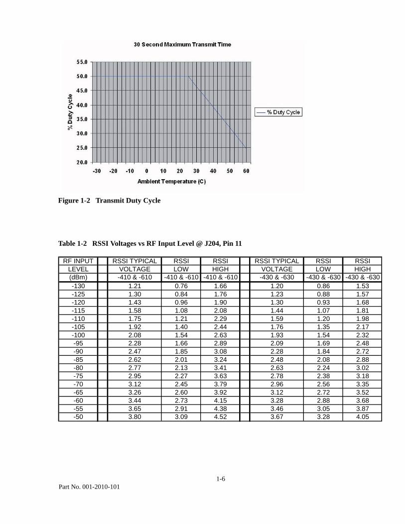
Figure 1-2 Transmit Duty Cycle
Table 1-2 RSSI Voltages vs RF Input Level @ J204, Pin 11
RF INPUT RSSI TYPICAL RSSI RSSI RSSI TYPICAL RSSI RSSILEVEL VOLTAGE LOW HIGH VOLTAGE LOW HIGH(dBm) -410 & -610 -410 & -610 -410 & -610 -430 & -630 -430 & -630 -430 & -630-130 1.21 0.76 1.66 1.20 0.86 1.53-125 1.30 0.84 1.76 1.23 0.88 1.57-120 1.43 0.96 1.90 1.30 0.93 1.68-115 1.58 1.08 2.08 1.44 1.07 1.81-110 1.75 1.21 2.29 1.59 1.20 1.98-105 1.92 1.40 2.44 1.76 1.35 2.17-100 2.08 1.54 2.63 1.93 1.54 2.32-95 2.28 1.66 2.89 2.09 1.69 2.48-90 2.47 1.85 3.08 2.28 1.84 2.72-85 2.62 2.01 3.24 2.48 2.08 2.88-80 2.77 2.13 3.41 2.63 2.24 3.02-75 2.95 2.27 3.63 2.78 2.38 3.18-70 3.12 2.45 3.79 2.96 2.56 3.35-65 3.26 2.60 3.92 3.12 2.72 3.52-60 3.44 2.73 4.15 3.28 2.88 3.68-55 3.65 2.91 4.38 3.46 3.05 3.87-50 3.80 3.09 4.52 3.67 3.28 4.05

1-7Part No. 001-2010-101
Figure 1-4 Typical Output Power vs Supply Voltage
SECTION 2
INSTALLATION
2-1
Part No. 001-2010-101
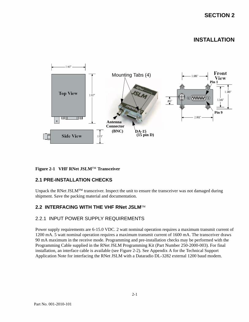
Figure 2-1 VHF RNet JSLM™ Transceiver
2.1 PRE-INSTALLATION CHECKS
Unpack the RNet JSLM™ transceiver. Inspect the unit to ensure the transceiver was not damaged during shipment. Save the packing material and documentation.
2.2 INTERFACING WITH THE VHF RNet JSLM™
2.2.1 INPUT POWER SUPPLY REQUIREMENTS
Power supply requirements are 6-15.0 VDC. 2 watt nominal operation requires a maximum transmit current of 1200 mA. 5 watt nominal operation requires a maximum transmit current of 1600 mA. The transceiver draws 90 mA maximum in the receive mode. Programming and pre-installation checks may be performed with the Programming Cable supplied in the RNet JSLM Programming Kit (Part Number 250-2000-003). For final installation, an interface cable is available (see Figure 2-2). See Appendix A for the Technical Support Application Note for interfacing the RNet JSLM with a Dataradio DL-3282 external 1200 baud modem.
DA-15 (15 pin D)
Antenna Connector
(BNC)
Mounting Tabs (4)
Pin 1
Pin 9Pin 1
Pin 9

2-2Part No. 001-2010-101
2.2.2 ANTENNA AND VSWR
A Voltage Standing Wave Ratio (VSWR) measurement of the antenna system should be made before the transceiver is put into service. An accurate VSWR meter or directional wattmeter appropriate for the frequency of operation should be used. A VSWR of less than 2:1 is recommended. If the VSWR reading is high, check cables and connectors. Verify that the antenna is properly installed and is specified to operate on your frequency.
2.2.3 RECEIVER SELECTIVITY ADJUSTMENT
Revisions A through I of the VHF RNet JSLM receiver have a manual adjustment for the receiver front end filter selectivity accessible through the rubber plug in the case of the radio (see Transceiver Identification - page 1-1 to identify the revision of your unit). The front-end filter is 6 MHz wide and is centered from the factory at 141.000 MHz for 132-150 MHz radios and at 162.000 MHz for 150-174 MHz radios. To set the filter selectivity to the desired frequency of operation, refer to section 5.2.1 on page 5-1. The receiver front end filter is electronically tuned on revisions J and later. No adjustment is necessary.
2.2.4 CONNECTOR J204 USER INTERFACE
Connector J204 (DA-15) provides the interface with the VHF RNet JSLM transceiver. This is a 15-pin, female connector. See Appendix A for the Technical Support Application Note for interfacing the RNet JSLM with a Dataradio DL-3282 external 1200 baud modem.
2.2.5 GENERAL PINOUT DESCRIPTION
Table 2-1 Channel Select Table
NOTE: CSO_N.... CS2_N internally pulled up to 5 Vdc, ground pin for logic low.
PIN 1: Channel Select 0 (CSO_N) Switch 0
PIN 2: Channel Select 1 (CS1_N) Switch 1
PIN 3: Channel Select 2 (CS2_N) Switch 2
PIN 4: TX Microphone Input (MIC_IN) 25 mVrms nominal for 60% rated deviation.
PIN 5: Channel Select for XTAL Compatibility Mode (CSN_N) Open for channel 1, ground for channel 2.
CH CSO_N CS1_N CS2_N 1 0 0 0 2 1 0 0 3 0 1 0 4 1 1 0 5 0 0 1 6 1 0 1 7 0 1 1 8 1 1 1
2-3
Part No. 001-2010-101
PIN 6: Raw Battery Supply (7.5 or 11.25 VDC nominal) Input power supply 6-15.0 VDC, 3 Amps maximum.
PIN 7: TX Auxiliary Input (AUX_IN) Audio input for the transmitter. Without pre-emphasis: 40 mVrms nominal for 60% rated deviation. With pre-emphasis: 200 mVrms nominal for 60% rated deviation.
PIN 8: RX Auxiliary Output (AUX_OUT): Audio from the receiver. Without pre-emphasis: 212 mVrms +/- 18 mV (0.6 Vp-p ± 0.05 Vp-p) With pre-emphasis: 160 mVrms +/- 18 mV (0.45 Vp-p ± 0.05 Vp-p) Into a 600 ohm load
PIN 9: Program I/O From Computer (PGM_IN_OUT) (TTL) The interface cable included with the JSLM Field Programming Software Kit (see Table 1-1) converts RS-232 to TTL logic for RNet JSLM programming information.
PIN 10: Ready to Send (RS) (TTL levels), radio is locked on frequency and transmitter is ready to accept audio input, set with software active high or low.
PIN 11: Software programmable to: Receive_Monitor - Carrier Detect Override, disables squelch, can be enabled with software or
by manually grounding pin 11.RSSI Analog Out - RSSI DC output voltage level
PIN 12: RX Audio Out (AUDIO_OUT) Audio from the receiver. 212 mVrms +/- 18 mV (0.6 Vp-p ± 0.05 Vp-p) into a 2k ohm load, AC coupled.
PIN 13: Carrier Detect (DCD) Carrier Detect (TTL logic). Indicates receiver is locked on channel and receiving a signal. Can be active high or low, set with software.
PIN 14: Push To Talk (PTT_RTS)(TTL levels) Keys the transmitter. Can be active high or low, set with software.
Pin 15: Ground
2-4Part No. 001-2010-101
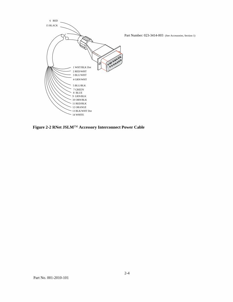
Figure 2-2 RNet JSLM™ Accessory Interconnect Power Cable
5 BLU/BLK
3 BLU/WHT2 RED/WHT1 WHT/BLK Dot
9 GRN/BLK10 ORN/BLK11 RED/BLK12 ORANGE13 BLK/WHT Dot14 WHITE
6 RED
15 BLACK
4 GRN/WHT
7 GREEN8 BLUE
Part Number: 023-3414-003 (See Accessories, Section 1)
SECTION 3
PROGRAMMING
3-1
Part No. 001-2010-101
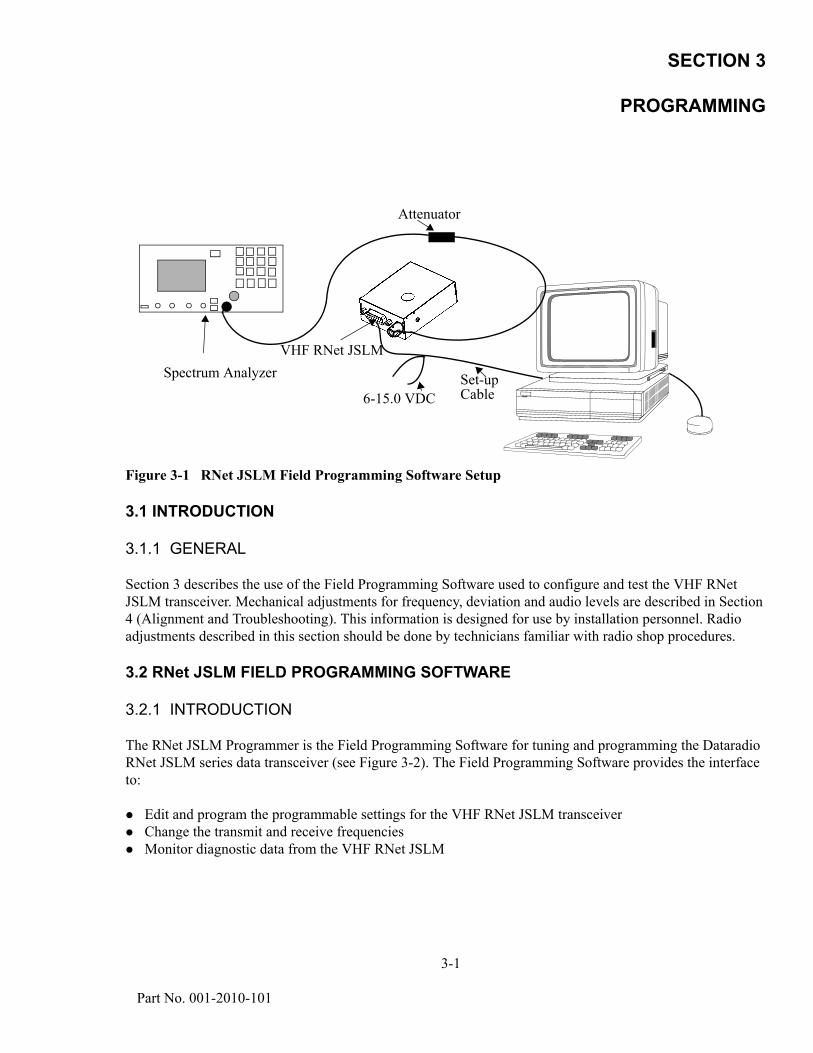
Figure 3-1 RNet JSLM Field Programming Software Setup
3.1 INTRODUCTION
3.1.1 GENERAL
Section 3 describes the use of the Field Programming Software used to configure and test the VHF RNet JSLM transceiver. Mechanical adjustments for frequency, deviation and audio levels are described in Section 4 (Alignment and Troubleshooting). This information is designed for use by installation personnel. Radio adjustments described in this section should be done by technicians familiar with radio shop procedures.
3.2 RNet JSLM FIELD PROGRAMMING SOFTWARE
3.2.1 INTRODUCTION
The RNet JSLM Programmer is the Field Programming Software for tuning and programming the Dataradio RNet JSLM series data transceiver (see Figure 3-2). The Field Programming Software provides the interface to:
Edit and program the programmable settings for the VHF RNet JSLM transceiverChange the transmit and receive frequenciesMonitor diagnostic data from the VHF RNet JSLM
Attenuator
Set-upCable6-15.0 VDC
Spectrum AnalyzerVHF RNet JSLM

3-2
Part No. 001-2010-101
Figure 3-2 RNet JSLM Field Programming Software Start-up Screen
3.2.2 SETUP MODEM/RADIO PARAMETERS
The Setup JLSM Parameters screen allows the user to view and edit the RNet JSLM’s programmable parameters (see Figure 3-3). The programmable parameters can be stored in a data file with the .DAT file extension by selecting “Save Data File” from the file menu. These programmable parameters are used by the Read/Write Parameters screen for programming into nonvolatile memory of the RNet JSLM.
3.2.2.1 SETTINGS TAB
The Settings tab allows the user to program various RNet JSLM operating parameters (see Figure 3-3).
ID Number
The electronic ID Number is a unique number assigned at the factory. In the case of a duplication, this number may be changed. The ID Number is used by the Field Programming Software for remote addressing and diagnostics.
The range of this field is 1 to 999999999. A value of -1 would indicate factory values were lost and default values were loaded automatically by the RNet JSLM.NOTE: This ID is not the same as the printed serial number. Use the printed serial number to identify the unit’s warranty status.
3-3 Part No. 001-2010-101
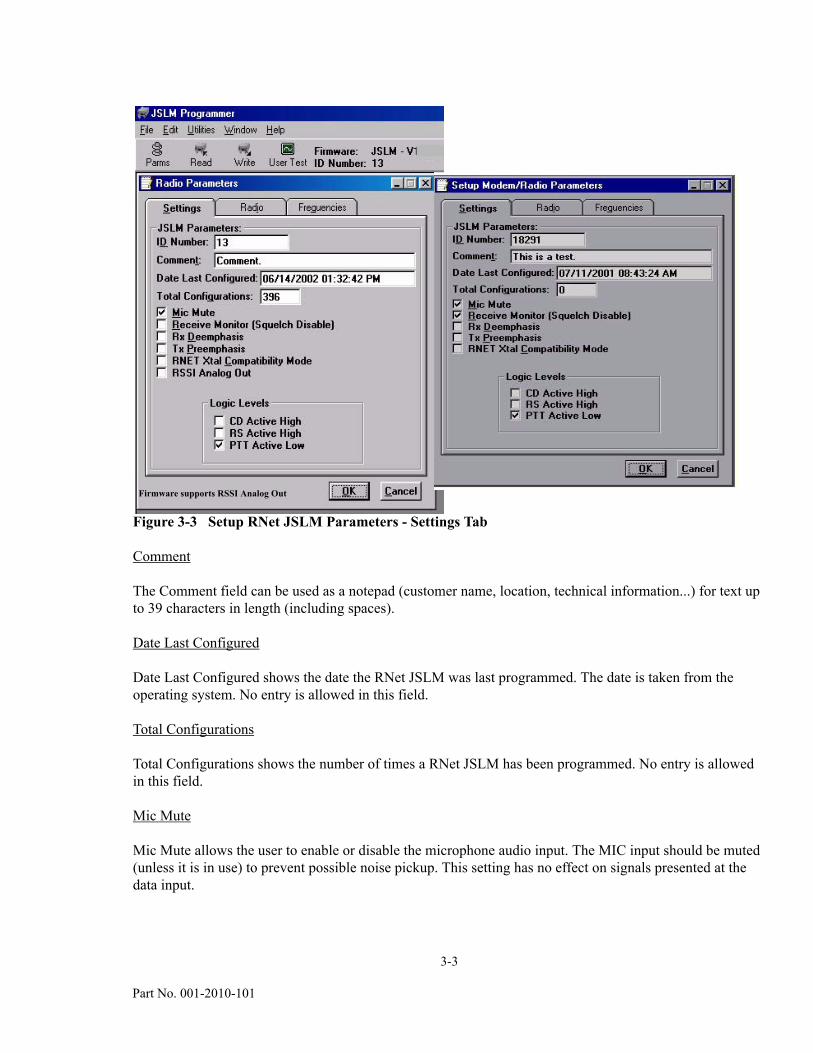
Figure 3-3 Setup RNet JSLM Parameters - Settings Tab
Comment
The Comment field can be used as a notepad (customer name, location, technical information...) for text up to 39 characters in length (including spaces).
Date Last Configured
Date Last Configured shows the date the RNet JSLM was last programmed. The date is taken from the operating system. No entry is allowed in this field.
Total Configurations
Total Configurations shows the number of times a RNet JSLM has been programmed. No entry is allowed in this field.
Mic Mute
Mic Mute allows the user to enable or disable the microphone audio input. The MIC input should be muted (unless it is in use) to prevent possible noise pickup. This setting has no effect on signals presented at the data input.
Firmware supports RSSI Analog Out
3-4
Part No. 001-2010-101
Receiver Monitor (Squelch Disable)
Receiver Monitor (Squelch Disable) allows the user to choose a continuous or switched Rx output for Carrier Detect (CD). This switch controls both voice and data outputs. Normally these outputs are controlled by the carrier detect circuit to turn on audio output only when a signal is received. (Similar to a squelch function). Checking this box will leave the audio output active when no signal is present (for monitoring purposes). The receiver output is always muted during transmissions, regardless of switch setting. Default value for Receive Monitor (Squelch Disable) is disabled (unchecked).
Note: If the Receiver Monitor input on the data connector is pulled low, Rx output will be “always active” regardless of switch setting.
Rx De-emphasis
Rx De-emphasis is enabled for Rx data output. Since data equipment normally requires a flat audio response, the default (“flat”) setting is preferred. If de-emphasis is selected, the data output is passed through a 300 Hz - 3 kHz bandpass filter and a 6 dB per octave de-emphasis circuit. Default value for Rx De-emphasis is disabled (unchecked).
Note: This setting does not affect the “mic” input of the RNet JSLM. Mic audio is always passed through the pre-emphasis circuit.
RNet Xtal Compatibility Mode
RNet Xtal Compatibility Mode sets characteristics for full compatibility with RNet 450 crystal-controlled models. If RNet Xtal Compatibility Mode is selected, the following settings are made:
Channel selection is limited to 2 channels switched by pin 5 on the data connector - Pin 5 open = selects channel 1 - Pin 5 grounded = selects channel 2
Carrier Detect will be true during transmissions. Normally, Carrier Detect is false during transmissions
Default value for RNet Xtal Compatibility Mode is disabled (unchecked).
RSSI Analog Out
When RSSI Analog Out is enabled (checked), J204 (Pin 11) is switched from Receive Monitor (Squelch Disable) to a receive signal strength indicator voltage. The DC level at Pin 11 varies with the signal strength present at the RF input of the JSLM. Default value for RSSI Analog Out is disabled (unchecked).The RSSI Analog Out check box will appear on the Setup JSLM Parameters Screen if this feature is supported by the unit’s firmware (see Figure 3-3).
Logic Levels
Logic Levels allows the user to select the polarity of some pins on the data interface connector. The Carrier Detect (CD), Ready to Send (RS) and Push to Talk (PTT) polarity is programmable as Active High or Active Low.
3.2.2.2 RADIO TAB
The Radio tab allows user programming of radio operating parameters.
3-5 Part No. 001-2010-101
Radio Parameters
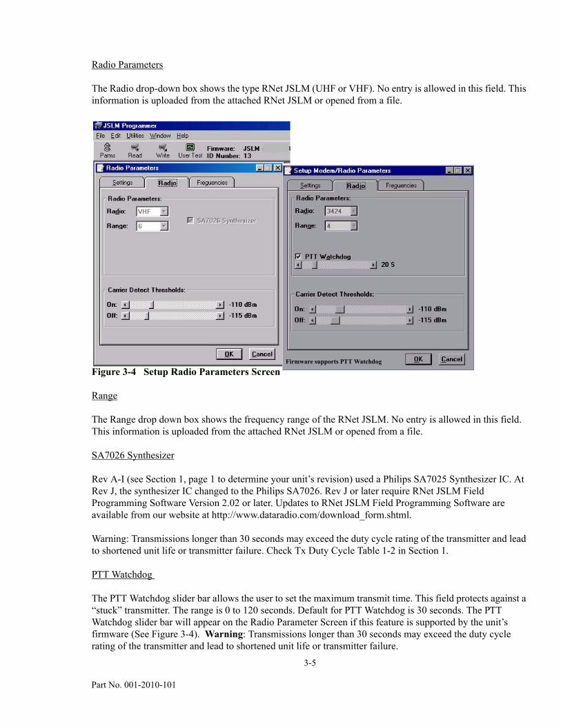
The Radio drop-down box shows the type RNet JSLM (UHF or VHF). No entry is allowed in this field. This information is uploaded from the attached RNet JSLM or opened from a file.
Figure 3-4 Setup Radio Parameters Screen
Range
The Range drop down box shows the frequency range of the RNet JSLM. No entry is allowed in this field. This information is uploaded from the attached RNet JSLM or opened from a file.
SA7026 Synthesizer
Rev A-I (see Section 1, page 1 to determine your unit’s revision) used a Philips SA7025 Synthesizer IC. At Rev J, the synthesizer IC changed to the Philips SA7026. Rev J or later require RNet JSLM Field Programming Software Version 2.02 or later. Updates to RNet JSLM Field Programming Software are available from our website at http://www.dataradio.com/download_form.shtml.
Warning: Transmissions longer than 30 seconds may exceed the duty cycle rating of the transmitter and lead to shortened unit life or transmitter failure. Check Tx Duty Cycle Table 1-2 in Section 1.
PTT Watchdog
The PTT Watchdog slider bar allows the user to set the maximum transmit time. This field protects against a “stuck” transmitter. The range is 0 to 120 seconds. Default for PTT Watchdog is 30 seconds. The PTT Watchdog slider bar will appear on the Radio Parameter Screen if this feature is supported by the unit’s firmware (See Figure 3-4). Warning: Transmissions longer than 30 seconds may exceed the duty cycle rating of the transmitter and lead to shortened unit life or transmitter failure.
Firmware supports PTT Watchdog

3-6
Part No. 001-2010-101
Carrier Detect On Threshold
Carrier Detect On Threshold indicates the RSSI level for a received carrier. The Carrier Detect On Threshold value should be greater than (a less negative number) the Carrier Detect Off Threshold value.
Carrier Detect Off Threshold
Carrier Detect Off Threshold indicates the RSSI level for a lost carrier. The Carrier Detect Off Threshold value should be less than (larger negative number) the Carrier Detect On Threshold value.
3.2.2.3 FREQUENCIES TAB
The Frequencies tab is used for user programming of the eight frequency pairs.
Figure 3-5 Setup Frequencies Screen
Chan
Chan displays the frequency channel pair.
Rx Frequency
Rx Frequency displays the receive frequency for the channel pair (in MHz).
Tx Frequency
Tx Frequency displays the transmit frequency for the channel pair (in MHz).

3-7 Part No. 001-2010-101
Default Freqs
The Default Freqs button returns the Rx and Tx frequencies to default values. The default frequencies are based on radio type and range.
3.2.3 VERSION REQUEST
Version Request displays RNet JSLM hardware and firmware version information.
3.2.4 READ/WRITE PROGRAMMABLE SETTINGS
Read Programmable Settings
Read Programmable Settings reads and displays the programmable settings currently programmed in the EEPROM of the RNet JSLM.
Write Programmable Settings
Write Programmable Settings writes the currently loaded settings to the EEPROM of the RNet JSLM.
Clone Programmable Settings
Clone Programmable Settings clones (writes) the currently loaded programmable settings (except ID Number, Comment and Number of Writes) to the EEPROM of the RNet JSLM. Clone Programmable Settings is used to program a Data File (.DAT) to multiple RNet JSLMs.
3.2.5 PORT SETTINGS
Port Settings are used to configure the user PC’s serial COM ports (Primary and Secondary). Port Settings can be used to test data links using the ASCII and HEX terminals (available in the Utilities menu). The RNet JSLM Field Programming Software will override these settings when using any other screen to communicate with the RNet JSLM. NOTE: A modem is required to transmit serial data using this program. The RNet JSLM is an analog signal device.

3-8
Part No. 001-2010-101
Figure 3-6 Serial PC Port Settings Screens
COM Port
The COM Port field allows the user to select the COM port number (1-4) for the Primary and Secondary COM port.
Baud Rate
The Baud Rate field allows the user to select the communication speed for the Primary and Secondary COM ports.
Data Bits
The Data Bits field allows the user to select the number of Data Bits (4 - 8) to transmit or receive over the Primary and Secondary COM ports.
Parity
The Parity field permits the user to select Parity Bits (None/Odd/Even) to transmit or receive for the Primary and Secondary COM ports.
Stop Bits
The Stop Bits field permits the user to select the number of Stop Bits (1 or 2) to transmit or receive for the Primary and Secondary COM Ports.
3-9 Part No. 001-2010-101
DTR Enable
The DTR field allows the user to select whether the DTR (Data Terminal Ready) line of the RS-232 port is asserted when the port is open for the Primary and Secondary COM ports.
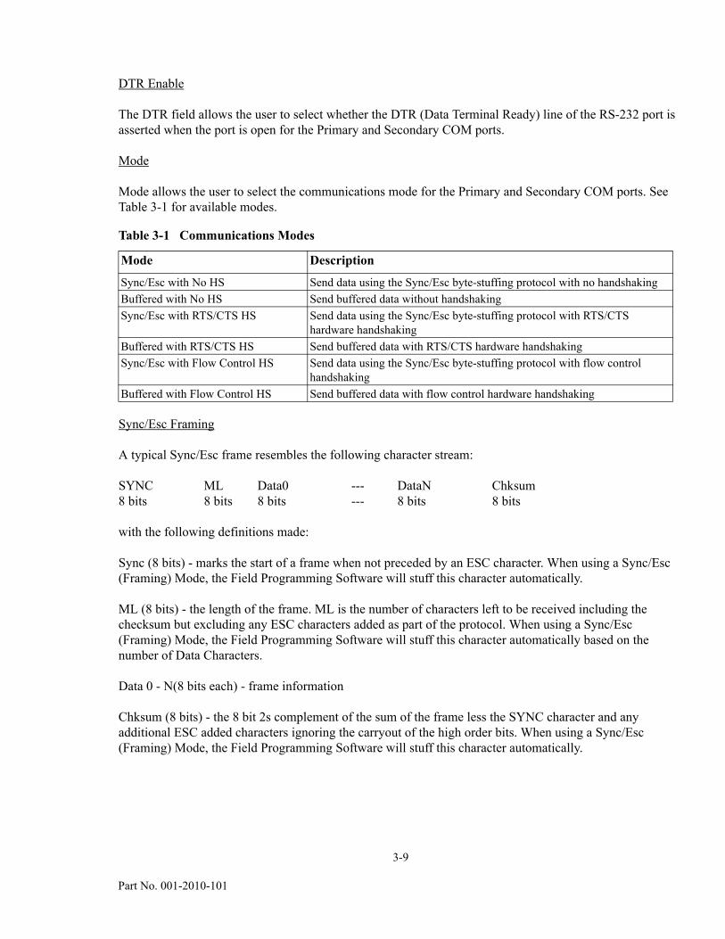
Mode
Mode allows the user to select the communications mode for the Primary and Secondary COM ports. See Table 3-1 for available modes.
Sync/Esc Framing
A typical Sync/Esc frame resembles the following character stream:
SYNC ML Data0 --- DataN Chksum 8 bits 8 bits 8 bits --- 8 bits 8 bits
with the following definitions made:
Sync (8 bits) - marks the start of a frame when not preceded by an ESC character. When using a Sync/Esc (Framing) Mode, the Field Programming Software will stuff this character automatically.
ML (8 bits) - the length of the frame. ML is the number of characters left to be received including the checksum but excluding any ESC characters added as part of the protocol. When using a Sync/Esc (Framing) Mode, the Field Programming Software will stuff this character automatically based on the number of Data Characters.
Data 0 - N(8 bits each) - frame information
Chksum (8 bits) - the 8 bit 2s complement of the sum of the frame less the SYNC character and any additional ESC added characters ignoring the carryout of the high order bits. When using a Sync/Esc (Framing) Mode, the Field Programming Software will stuff this character automatically.
Table 3-1 Communications Modes
Mode Description
Sync/Esc with No HS Send data using the Sync/Esc byte-stuffing protocol with no handshaking Buffered with No HS Send buffered data without handshakingSync/Esc with RTS/CTS HS Send data using the Sync/Esc byte-stuffing protocol with RTS/CTS
hardware handshakingBuffered with RTS/CTS HS Send buffered data with RTS/CTS hardware handshakingSync/Esc with Flow Control HS Send data using the Sync/Esc byte-stuffing protocol with flow control
handshakingBuffered with Flow Control HS Send buffered data with flow control hardware handshaking
3-10
Part No. 001-2010-101
Swap COM Ports
Swap COM Ports allows the user to swap the Primary and Secondary COM ports. For example, if the Primary is COM1 and the Secondary is COM2, the Primary becomes COM2 and the Secondary becomes COM1 after a Swap COM Ports is issued. This utility is useful when more than one RNet JSLM is connected to a PC since the programming screens all use the Primary COM port. By issuing a Swap COM Ports, the RNet JSLM connected to the second COM port can be programmed without switching cables.
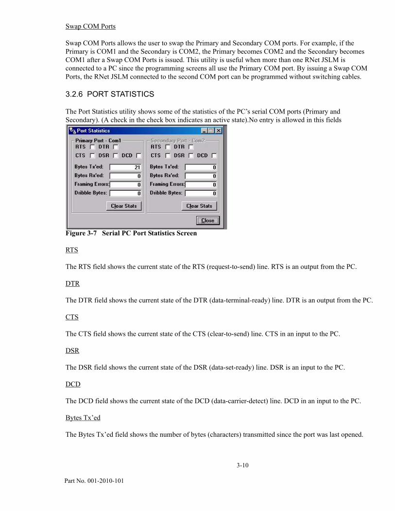
3.2.6 PORT STATISTICS
The Port Statistics utility shows some of the statistics of the PC’s serial COM ports (Primary and Secondary). (A check in the check box indicates an active state).No entry is allowed in this fields
Figure 3-7 Serial PC Port Statistics Screen
RTS
The RTS field shows the current state of the RTS (request-to-send) line. RTS is an output from the PC.
DTR
The DTR field shows the current state of the DTR (data-terminal-ready) line. DTR is an output from the PC.
CTS
The CTS field shows the current state of the CTS (clear-to-send) line. CTS in an input to the PC.
DSR
The DSR field shows the current state of the DSR (data-set-ready) line. DSR is an input to the PC.
DCD
The DCD field shows the current state of the DCD (data-carrier-detect) line. DCD in an input to the PC.
Bytes Tx’ed
The Bytes Tx’ed field shows the number of bytes (characters) transmitted since the port was last opened.
3-11 Part No. 001-2010-101
Bytes Rx’ed
The Bytes Rx’ed field shows the number of bytes (characters) received since the port was last opened.
Framing Errors
The Framing Errors field shows the number of Framing Errors received since the port was last opened.
Dribble Bytes
The Dribble Bytes field shows the number of extra (not expected) bytes (characters) received since the port was last opened.
3.2.7 USER TEST
The User Test Utility allows the user to test the functionality of the RNet JSLM. This utility makes diagnostic information available and gives the user the ability to change channels and transmit or receive a modulated signal.
Diagnostics
Select
The Select drop down box allows the user to select Current, Low or High diagnostics. Current shows the parameter value when last requested. Low shows the lowest parameter value since the last Clear was performed or power removed. High shows the highest value for the parameter since the last Clear was performed or power removed.
Clear
The Clear field allows the user to clear the unit’s lowest or highest records for diagnostics.
3-12
Part No. 001-2010-101
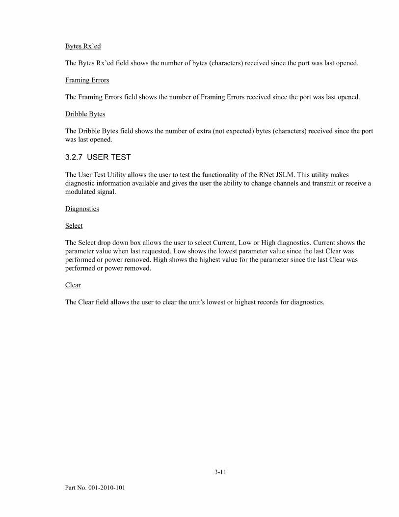
Figure 3-8 RNet JSLM User Test Screen
Diagnostic parameters include:
Battery Voltage - Supply voltage (in volts)Analog Vcc - Analog Circuits regulated 5V lineTemperature - Internal case temperature (in Celsius)RSSI Level - Received Signal Strength indicator (in dBm)XCVR Status - State of transceiver (receiving or transmitting)Synth Lock - indicates synthesizer lock or unlocked statusWD Status - Indicates normal (okay to transmit) or Overvoltage (maximum supply voltage exceeded)
RSSI
The RSSI panel shows the current RSSI (received signal strength indicator) level (in dBm) while the local unit is receiving.
Channel
The Channel field allows the user to select one of the 8 programmed channels.
Rx/Tx Frequency
The Rx and Tx Frequency fields display the current receive and transmit frequencies.
3-13 Part No. 001-2010-101
F5
Pressing the F5 key causes the unit to transmit on the programmed transmit frequency.
F6
Pressing the F6 key causes the unit to go to receive on the programmed receive frequency.
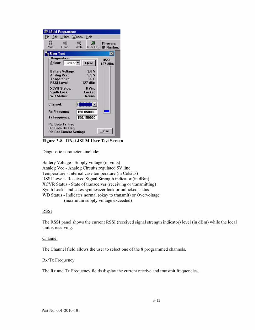
3.2.8 ASCII / HEX TERMINAL
The Terminal Screens allow the user to select an ASCII or Hexadecimal Terminal Screen for the Primary and Secondary COM ports that were configured in the Port Settings screen. The data is sent according to the port configuration (setup in the Port Settings screen).
Figure 3-9 ASCII Terminal Screen
ASCII Terminal
Primary - selects an ASCII Terminal screen to send and receive ASCII data on the Primary COM port (setup the Port Settings).
3-14 Part No. 001-2010-101
Secondary - selects an ASCII Terminal screen to send and receive ASCII data on the Secondary COM port (setup in Port settings).
Hex Terminal
Primary - selects a Hexadecimal Terminal screen to send and receive Hexadecimal data on the Primary COM port (setup the Port Settings).
Secondary - selects a Hexadecimal Terminal screen to send and receive Hexadecimal data on the Secondary COM port (setup in Port settings).
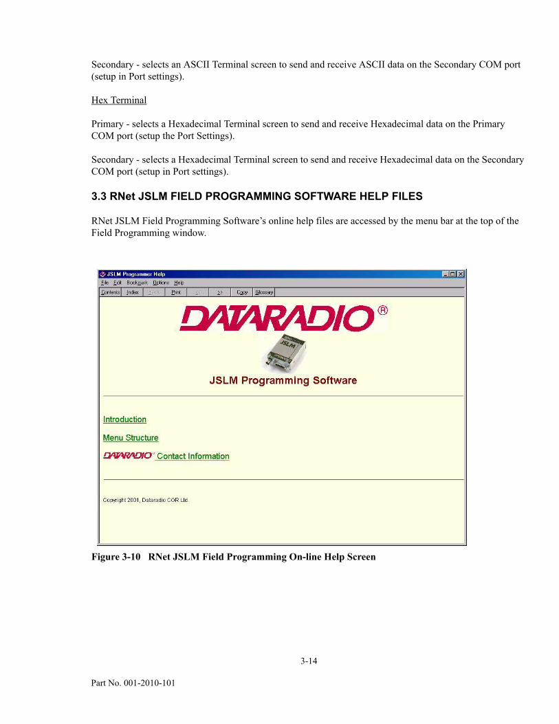
3.3 RNet JSLM FIELD PROGRAMMING SOFTWARE HELP FILES
RNet JSLM Field Programming Software’s online help files are accessed by the menu bar at the top of the Field Programming window.
Figure 3-10 RNet JSLM Field Programming On-line Help Screen
SECTION 4
ALIGNMENT AND TROUBLESHOOTING
4-1
Part Number 001-2010-101
4.1 GENERAL
4.1.1 PERIODIC CHECKS
This transceiver should be put on a regular maintenance schedule and an accurate performance record maintained. Important checks are receiver sensitivity, transmitter frequency, modulation, and power output. A procedure for these and other tests is located in Section 4.2.1. It is recommended that transceiver performance be checked annually even though periodic checks are not required by the FCC.
4.1.2 SERVICING
The majority of the components used on the printed circuit boards are surface mount devices. JSLM transceiver component level field repair is not recommended. Specialized training and equipment are required to service board level components. Equipment should be returned to the factory for repair.
4.2. PERFORMANCE CHECKS
4.2.1 FRONT-END TUNING
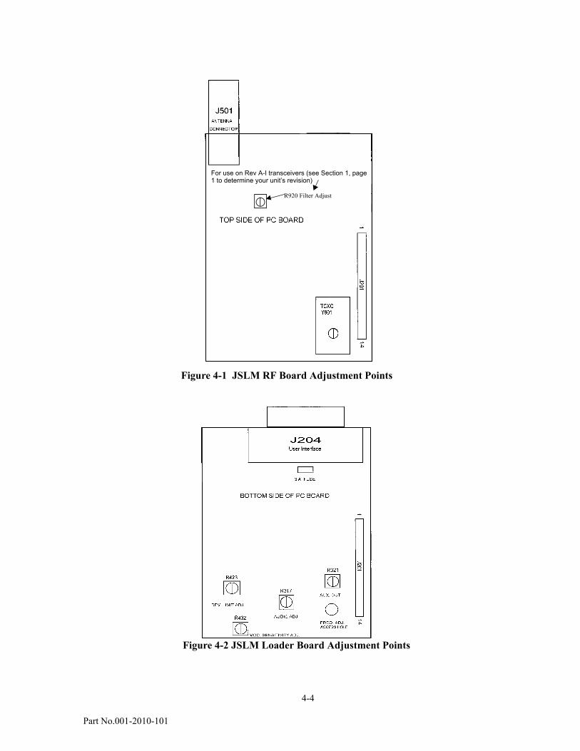
The front-end filters provide protection from strong, unwanted signals. On Rev A-I transceivers (see Section 1, page 1 to determine your unit’s revision), the filter bandwidth is approximately 6 MHz and can be tuned across the entire operational bandwidth (132-150 or 150-174 MHz). To tune the filters to the operating frequency, remove the rubber hole plug on the chassis and apply an on-channel modulated signal to the antenna connector. Use a small insulated screw driver to adjust R920 through the chassis hole for best SINAD or recovered audio. The RSSI Indicator display (using the Field Programming Software) should be used to peak the receive signal strength or by measuring carrier detect on pin 13 (J204) with a voltmeter while tuning R920. On Rev J or later transceivers, the front end filter is electronically tuned. No adjustments are necessary.
4.2.2 CHANNEL FREQUENCY
The transceiver frequency is controlled by a temperature compensated crystal oscillator (TCXO) which has a frequency stability of ± 2.5 parts per million over a temperature range of -30 to + 60° C. When transmitting (for example) at 150 MHz, the output frequency should be 150 MHz ± 375 Hz over temperature. The operating frequency may be adjusted through the case of the JSLM. Connect the User Interface Cable included in the RNet JSLM Field Programming Kit (250-2000-003). Connect the antenna port to a frequency counter or other frequency measurement instrument. Locate the Frequency Adjust Access Hole on the case of the VHF RNet JSLM (see Figure 4-2). Enable the transmitter PTT Line and use a small screwdriver to adjust the TCXO for the desired transmit frequency.
Caution: An RF attentuator may be required depending on the power handling capability of the measuring instrument.

4-2
Part No.001-2010-101
4.2.3 RF OUTPUT POWER
The RF output power may be verified with an accurate power meter connected with a short 50 ohm cable to the Antenna Connector. The transceiver typically provides 5 Watts ± 20% at 11.25 Vdc across the specified band. At 7.5 Vdc output power is reduced to 2 Watts ± 20%. Transmitter alignment is performed in the factory and is not a recommended field adjustment.
NOTE: Transmit duty cycle must also be considered when making power measurements, see Section 1, Figure 1-3 for recommended duty cycle specifications.
4.2.4 TRANSMIT DEVIATION LIMITING
Deviation limiting is a factory adjustment that ensures the transmitter is not over-modulated when audio input signal levels vary. Deviation limiting may be verified by applying a 1 kHz, 1 Vrms audio signal to the Mic. or Aux_Input on J204. Apply PTT and observe the frequency deviation on a modulation analyzer (or similar equipment). The peak deviation should be ± 2.5 kHz for 12.5 kHz channel transmitters and ± 5 kHz for 25 channel transmitters. If adjustment is required, locate R423 on the Loader Board (see Figure 4-2). Apply the previously mentioned signal and adjust R423 for a peak deviation of < 2.5 kHz or < 5 kHz (whichever is applicable).
4.2.5 TRANSMIT DEVIATION
Transmitter deviation is preset by the factory and is adjustable via R432 on the Loader Board (see Figure 4-2) when using the Aux_Input on the User Interface J204. Refer to General Information, Section 1 for specifications and levels.
4.2.6 RECEIVE AUDIO LEVEL
Receive audio levels are preset by the factory, refer to General Information, Section 1, for specifications and levels. The Auxiliary audio output can be programmed for de-emphasis or flat response, (refer to Programming, Section 3). The level may be adjusted via R321. The audio output provides standard de-emphasis only and can be adjusted via R317. Refer to Figure 4-2 for adjustment locations.
4-3 Part No.001-2010-101
4.3 TROUBLESHOOTING
PROBLEM
Radio Inoperative
CHECKVerify the DC power source is properly connected. Verify DC power source is set at the correct voltage.Check the fuse on the Loader Board (see Figure 4-2).
PROBLEM
No/Poor Transmit
CHECKVerify power supply voltage. Verify power supply voltage can source 1600 mA minimum.Verify proper programming including frequency.Check system VSWR, feedline loss, connectors, and antenna.Check radio output power with wattmeter.
PROBLEM
No/Poor Receive
CHECKVerify Power Supply voltage.Verify proper receive frequency programming.Verify proper adjustment of front-end filter (on Rev A - I transceivers), see section 4.2.1.Check feedline loss, connectors and antenna.Apply -100 dBm RF signal at antenna connector and check RSSI indicator in the User Test utility of the RNet JSLM Field Programming SoftwareVerify that the channel is unoccupied.
4-4
Part No.001-2010-101
Pot R541R920 Filter Adjust
C554, C527 Transmit Tuners
Figure 4-1 JSLM RF Board Adjustment Points
Figure 4-2 JSLM Loader Board Adjustment Points
For use on Rev A-I transceivers (see Section 1, page 1 to determine your unit’s revision)
Appendix ATechnical Support Application Note
A-1001-2010-101
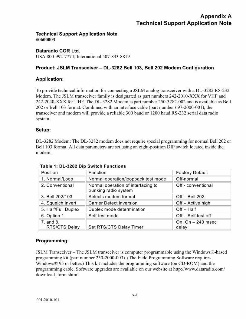
Technical Support Application Note#0600003
Dataradio COR Ltd.USA 800-992-7774; International 507-833-8819
Product: JSLM Transceiver – DL-3282 Bell 103, Bell 202 Modem Configuration
Application:
To provide technical information for connecting a JSLM analog transceiver with a DL-3282 RS-232 Modem. The JSLM transceiver family is designated as part numbers 242-2010-XXX for VHF and 242-2040-XXX for UHF. The DL-3282 Modem is part number 250-3282-002 and is available as Bell 202 or Bell 103 format. Combined with an interface cable (part number 697-2000-001), the transceiver and modem will provide a reliable 300 baud or 1200 baud RS-232 serial data radio system.
Setup:
DL-3282 Modem: The DL-3282 modem does not require special programming for normal Bell 202 or Bell 103 format. All data parameters are set using an eight-position DIP switch located inside the modem.
Programming:
JSLM Transceiver – The JSLM transceiver is computer programmable using the Windows®-based programming kit (part number 250-2000-003). (The Field Programming Software requires Windows® 95 or better.) This kit includes the programming software (on CD-ROM) and the programming cable. Software upgrades are available on our website at http://www.dataradio.com/download_form.shtml.
Table 1: DL-3282 Dip Switch FunctionsPosition Function Factory Default 1. Normal/Loop Normal operation/loopback test mode Off-normal 2. Conventional Normal operation of interfacing to
trunking radio system Off - conventional
3. Bell 202/103 Selects modem format Off – Bell 202 4. Squelch Invert Carrier Detect inversion Off – Active high 5. Half/Full Duplex Duplex mode determination Off – Half 6. Option 1 Self-test mode Off – Self test off 7. and 8. RTS/CTS Delay
Set RTS/CTS Delay Timer
On, On – 240 msec delay
A-2001-2010-101
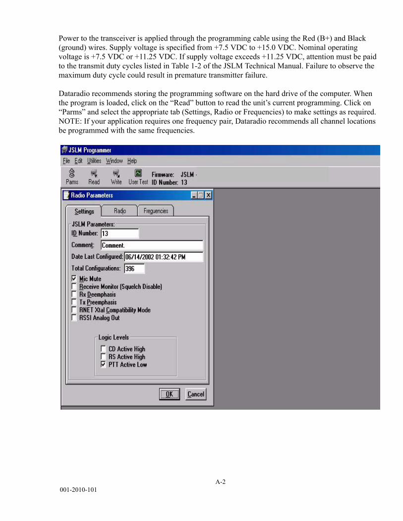
Power to the transceiver is applied through the programming cable using the Red (B+) and Black (ground) wires. Supply voltage is specified from +7.5 VDC to +15.0 VDC. Nominal operating voltage is +7.5 VDC or +11.25 VDC. If supply voltage exceeds +11.25 VDC, attention must be paid to the transmit duty cycles listed in Table 1-2 of the JSLM Technical Manual. Failure to observe the maximum duty cycle could result in premature transmitter failure.
Dataradio recommends storing the programming software on the hard drive of the computer. When the program is loaded, click on the “Read” button to read the unit’s current programming. Click on “Parms” and select the appropriate tab (Settings, Radio or Frequencies) to make settings as required. NOTE: If your application requires one frequency pair, Dataradio recommends all channel locations be programmed with the same frequencies.
A-3001-2010-101
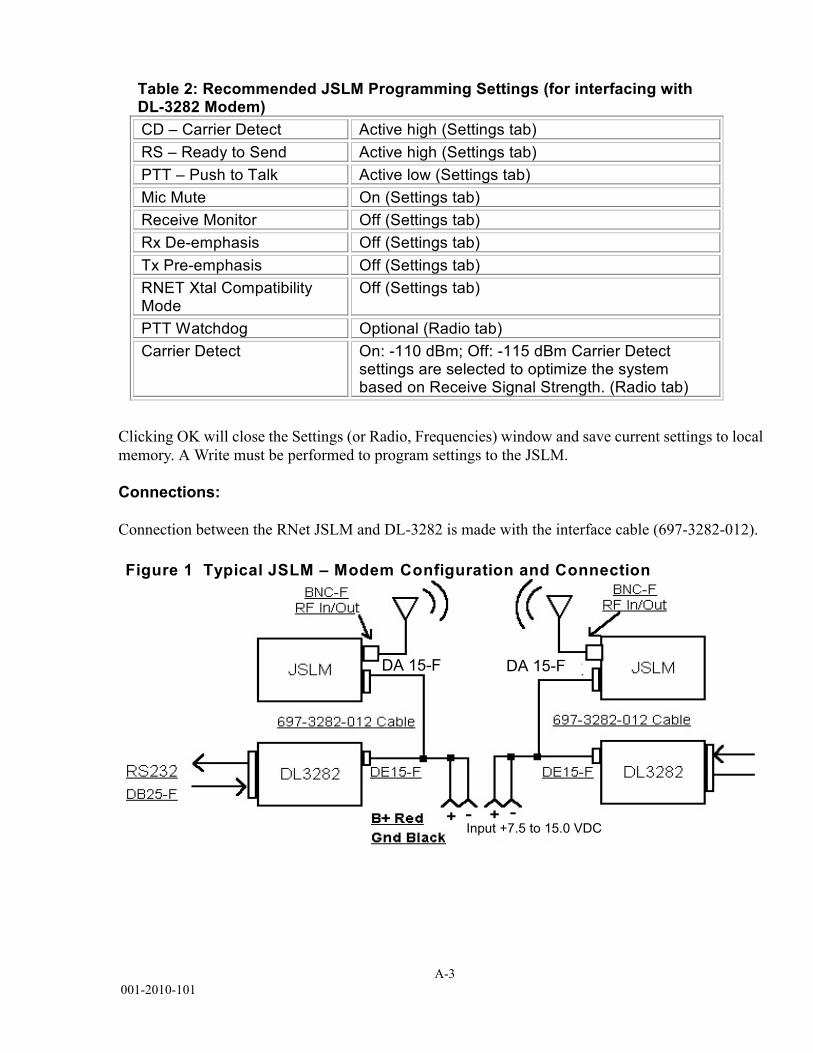
Clicking OK will close the Settings (or Radio, Frequencies) window and save current settings to local memory. A Write must be performed to program settings to the JSLM.
Connections:
Connection between the RNet JSLM and DL-3282 is made with the interface cable (697-3282-012).
Table 2: Recommended JSLM Programming Settings (for interfacing with DL-3282 Modem) CD – Carrier Detect Active high (Settings tab) RS – Ready to Send Active high (Settings tab) PTT – Push to Talk Active low (Settings tab) Mic Mute On (Settings tab) Receive Monitor Off (Settings tab) Rx De-emphasis Off (Settings tab) Tx Pre-emphasis Off (Settings tab) RNET Xtal Compatibility Mode
Off (Settings tab)
PTT Watchdog Optional (Radio tab) Carrier Detect On: -110 dBm; Off: -115 dBm Carrier Detect
settings are selected to optimize the system based on Receive Signal Strength. (Radio tab)
Figure 1 Typical JSLM – Modem Configuration and Connection
DA 15-FDA 15-F
Input +7.5 to 15.0 VDC

DATA TELEMETRY PRODUCT WARRANTY
Dataradio COR Ltd. ("DRL") warrants to the original purchaser for use("Buyer") that data telemetry products manufactured by DRL("Products") are free from defects in material and workmanship andwill conform to DRL's published technical specifications for a period of,except as noted below, two (2) years from the date of shipment toBuyer. DRL makes no warranty with respect to any equipment notmanufactured by DRL, and any such equipment shall carry the originalequipment manufacturer's warranty only. DRL further makes nowarranty as to and specifically disclaims liability for, availability, range,coverage, grade of service or operation of the repeater systemprovided by the carrier or repeater operator. Any return shippingcharges for third party equipment to their respective repair facilitiesare chargeable and will be passed on to the Buyer.
If any Product fails to meet the warranty set forth above during theapplicable warranty period and is returned to a location designated byDRL. DRL, at its option, shall either repair or replace such defectiveProduct, directly or through an authorized service agent, within thirty(30) days of receipt of same. No Products may be returned withoutprior authorization from DRL. Any repaired or replaced Products shallbe warranted for the remainder of the original warranty period. Buyershall pay all shipping charges, handling charges, fees and duties forreturning defective Products to DRL or DRL's authorized service agent.DRL will pay the return shipping charges if the Product is repaired orreplaced under warranty, exclusive of fees and duties. Repair orreplacement of defective Products as set forth in this paragraph fulfillsany and all warranty obligations on the part of DRL.
This warranty is void and DRL shall not be obligated to replace orrepair any Products if (i) the Product has been used in other than itsnormal and customary manner; (ii) the Product has been subject tomisuse, accident, neglect or damage or has been used other than withDRL approved accessories and equipment; (iii) unauthorized alterationor repairs have been made or unapproved parts have been used in orwith the Product; or (iv) Buyer failed to notify DRL or DRL's authorizedservice agent of the defect during the applicable warranty period. DRLis the final arbiter of such claims.
THE AFORESAID WARRANTIES ARE IN LIEU OF ALL OTHERWARRANTIES, EXPRESSED AND IMPLIED, INCLUDING BUT NOTLIMITED TO, ANY IMPLIED WARRANTY OF MERCHANTABILITY ORFITNESS FOR A PARTICULAR PURPOSE. DRL AND BUYER AGREETHAT BUYER'S EXCLUSIVE REMEDY FOR ANY BREACH OF ANY OFSAID WARRANTIES IT AS SET FORTH ABOVE. BUYER AGREES THATIN NO EVENT SHALL DRL BE LIABLE FOR INCIDENTAL, CONSEQUENTIAL, SPECIAL, INDIRECT OR EXEMPLARY DAMAGESWHETHER ON THE BASIS OF NEGLIGENCE, STRICT LIABILITY OROTHERWISE. The purpose of the exclusive remedies set forth aboveshall be to provide Buyer with repair or replacement of non-complyingProducts in the manner provided above. These exclusive remediesshall not be deemed to have failed of their essential purpose so longas DRL is willing and able to repair or replace non-complying Productsin the manner set forth above.
This warranty applies to all Products sold worldwide.
Some states do not allow limitations on implied warranties so theabove limitations may not be applicable. You may also have otherrights which vary from state to state.
EEXXCCEEPPTTIIOONNSS
OONNEE YYEEAARR: Labor to replace defective parts in repeaters orbase stations
TTHHIIRRTTYY DDAAYY: Tuning and adjustment of telemetry radios
NNOO WWAARRRRAANNTTYY: Fuses, lamps and other expendable parts
Effective 01/2004
W I R E L E S S D A T A
Dataradio COR Ltd. 299 Johnson Avenue, Suite 110, Waseca, MN 56093-0833: Tel: (507) 833-8819 or (800) 992-7774; Fax: (507) 833-6748 Visit us on the web at www.dataradio.com

Appendix CKorean Certification
C-1001-2010-101
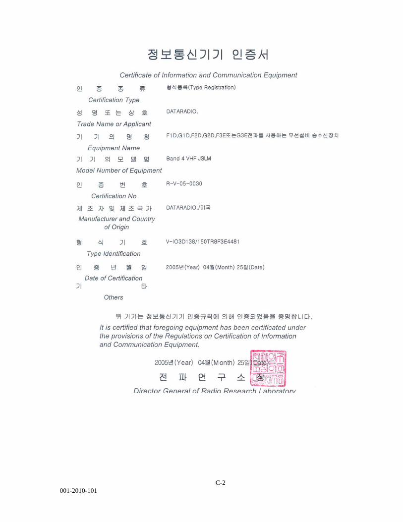
MIC MARK
The VHF RNet JSLM is certified for use in Korea under the following certification markings. See Appendix C
1. Type of equipment: Band 4 VHF JSLM: Type of equipment: Band 6 VHF JLSM:
2. Certification No. : R-V-05-0030:
3. Name of Certification Recipient: Dataradio:
4. Date of Manufacturer: 2005 04 25:
5. Manufacturer Nation: Dataradio/USA:
C-2001-2010-101

C-3001-2010-101


