Synthetic loading of three-phase induction motors using microprocessor controlled power electronics C. Grantham, PhD, CEng, FlEE M. Sheng, PhD E.D. Spooner, ME Indexing terms: Temperature measurement, Induction motors, Machine testing Abstract: The paper describes methods of loading three-phase induction motors, without the need to connect a load to the machine’s drive shaft. Two methods are described, one method uses microprocessor controlled power electronics to replace the electrical machines of an existing equivalent load technique. The second method uses microprocessor controlled power electronics to rapidly modulate the machine’s supply fre- quency. Both methods have the advantage of being extremely simple to set up and operate, and enable vertical motors to be tested in the same way as horizontal ones. The various power losses and their distribution in the machine during syn- thetic loading are calculated taking into account rotor parameter variations with frequency. If full load temperature rise is measured using the two methods described, results are obtained which are close to, but always higher than, those measured when using a conventional generator load and a 50 Hz inverter supply. List of symbols V, , V, = main and auxiliary supply voltages, V f., fb = main and auxiliary supply frequencies, Hz CO,, , ob = angular velocities of main and auxiliary rotat- o, =angular velocity of total flux wave, electric = total magnitude of flux, Wb = centre frequency for sweep frequency method, ing fields, electric rad/s rad/s t = time, s fi f, = sweep frequency, Hz sm = sweep magnitude, Hz R,, R, = stator and rotor resistances, R X,, X, = stator and rotor leakage reactances R R, = resistance in equivalent circuit magnetisation X, = reactance in equivalent circuit magnetisation P, = rotor copper loss, W Hz branch, R branch, R 0 IEE, 1994 Paper 9935B (Pl), lint received 11th June and in reviscd form 14th September 1993 The authors are with the Department of Electric Power Engineering, School of Electrical Engineexin& The University of New South Wales, P.O. Box 1, Kensington, NSW 2033, Australia IEE Proc.-Electr. Power Appl., Vol. 141, No. 2, March I994 =rotor copper loss for conventional full load = per-phase stator and rotor currents, A P,” I,, I, I,,, I,, = per-phase rated stator and rotor currents, A Pe = eddy-current loss, W ph = hysteresis loss, W PC = core loss, W PI = total copper and core losses, W PI, = total copper and core losses for conventional full load condition, W P = number of pairs of poles A4 = mutual inductance, H T = instantaneous electromagnetic torque, Nm 7’ = peak oscillating electromagnetic torque, Nm T. = rated electromagnetic torque, Nm 1 introduction Whether it be to establish that the insulation system of an induction motor is adequate for its intended use, or that the machine is suitable for application in a poten- tially explosive atmosphere, temperature rise assessment under full load conditions is of major importance. The conventional method of carrying out the necessary tem- perature rise test is to apply full load torque to the machine’s drive shaft. To load a large machine, equally large test equipment or a duplicate machine is required. The cost of setting up such a test facility, maintaining the equipment, and the time and setting up procedure for mechanically coupling the load machine, may make full load temperature tests prohibitively expensive. Vertically mounted motors are even more difficult to test [l-31 and may have to be fitted with special test bearings and tested horizontally. Clearly a method of establishing the rated temperature rise that does not require mechanically coupling a load is extremely useful. Several authors have recognised the need for such a synthetic loading method and several schemes have been developed. The method of Fong [4] whilst claiming to give excellent agreement with conventional loading, requires the use of two equally rated machines and requires up to 12 leads to be brought out of the machine under test. According to Kron [SI, as long ago as 1921, Ytterberg proposed connecting two voltage supplies of different frequencies in series with an induction motor to achieve synthetic loading; this technique is now generally known as the dual frequency (DF) method. Schwenk [l] reported that his company, West- inghouse Electric Corporation, has used the DF method of equivalent loading for several years. The DF method has also been incorporated in the Japanese Test Code for Induction Motors [SI. The method used by Schwenk has 101 condition, W
Transcript
Synthetic loading of three-phase induction motors using microprocessor controlled power electronics
C. Grantham, PhD, CEng, FlEE M. Sheng, PhD E.D. Spooner, ME
Indexing terms: Temperature measurement, Induction motors, Machine testing
Abstract: The paper describes methods of loading three-phase induction motors, without the need to connect a load to the machine’s drive shaft. Two methods are described, one method uses microprocessor controlled power electronics to replace the electrical machines of an existing equivalent load technique. The second method uses microprocessor controlled power electronics to rapidly modulate the machine’s supply fre- quency. Both methods have the advantage of being extremely simple to set up and operate, and enable vertical motors to be tested in the same way as horizontal ones. The various power losses and their distribution in the machine during syn- thetic loading are calculated taking into account rotor parameter variations with frequency. If full load temperature rise is measured using the two methods described, results are obtained which are close to, but always higher than, those measured when using a conventional generator load and a 50 Hz inverter supply.
List of symbols
V, , V, = main and auxiliary supply voltages, V f., fb = main and auxiliary supply frequencies, Hz CO,, , ob = angular velocities of main and auxiliary rotat-
o, =angular velocity of total flux wave, electric
= total magnitude of flux, Wb
= centre frequency for sweep frequency method,
ing fields, electric rad/s
rad/s
t = time, s fi
f, = sweep frequency, Hz sm = sweep magnitude, Hz R,, R, = stator and rotor resistances, R X,, X, = stator and rotor leakage reactances R R, = resistance in equivalent circuit magnetisation
X, = reactance in equivalent circuit magnetisation
P, = rotor copper loss, W
Hz
branch, R
branch, R
0 IEE, 1994 Paper 9935B (Pl), lint received 11th June and in reviscd form 14th September 1993 The authors are with the Department of Electric Power Engineering, School of Electrical Engineexin& The University of New South Wales, P.O. Box 1, Kensington, NSW 2033, Australia
IEE Proc.-Electr. Power Appl., Vol. 141, No. 2, March I994
=rotor copper loss for conventional full load
= per-phase stator and rotor currents, A
P,”
I , , I , I,,, I,, = per-phase rated stator and rotor currents, A Pe = eddy-current loss, W ph = hysteresis loss, W P C = core loss, W PI = total copper and core losses, W PI, = total copper and core losses for conventional
full load condition, W P = number of pairs of poles A4 = mutual inductance, H T = instantaneous electromagnetic torque, Nm 7’’ = peak oscillating electromagnetic torque, Nm T. = rated electromagnetic torque, Nm
1 introduction
Whether it be to establish that the insulation system of an induction motor is adequate for its intended use, or that the machine is suitable for application in a poten- tially explosive atmosphere, temperature rise assessment under full load conditions is of major importance. The conventional method of carrying out the necessary tem- perature rise test is to apply full load torque to the machine’s drive shaft. To load a large machine, equally large test equipment or a duplicate machine is required.
The cost of setting up such a test facility, maintaining the equipment, and the time and setting up procedure for mechanically coupling the load machine, may make full load temperature tests prohibitively expensive. Vertically mounted motors are even more difficult to test [l-31 and may have to be fitted with special test bearings and tested horizontally. Clearly a method of establishing the rated temperature rise that does not require mechanically coupling a load is extremely useful.
Several authors have recognised the need for such a synthetic loading method and several schemes have been developed. The method of Fong [4] whilst claiming to give excellent agreement with conventional loading, requires the use of two equally rated machines and requires up to 12 leads to be brought out of the machine under test. According to Kron [SI, as long ago as 1921, Ytterberg proposed connecting two voltage supplies of different frequencies in series with an induction motor to achieve synthetic loading; this technique is now generally known as the dual frequency (DF) method.
Schwenk [l] reported that his company, West- inghouse Electric Corporation, has used the DF method of equivalent loading for several years. The DF method has also been incorporated in the Japanese Test Code for Induction Motors [SI. The method used by Schwenk has
101
condition, W
the disadvantage that it requires two motor-generator (MG) sets to provide the DF supply and the secondary (i.e. lower frequency) power source must have all six leads brought out. A variation on this procedure requires only three leads to be brought out of the secondary source, but requires the additional use of an isolating trans- former. In both cases an MG set is used to provide the main supply. This is because if the motor under test was connected directly to the mains supply, light flicker may appear in areas fed from the same bus. In addition, it is helpful to have the supply voltage levels adjustable. The need for heavy equipment in a large test area and the complexity of the set up and operation procedure may make this scheme somewhat expensive. Furthermore, the MG sets are relatively expensive and need to be rated to cover the whole range of motors to be tested.
This paper describes methods of loading three-phase induction motors, using microprocessor controlled power electronic techniques and without the need to connect a load to the machine’s drive shaft. Two methods are described, one method uses microprocessor controlled power electronics to generate the two distinct frequencies and thereby replace the electrical machines of the existing DF technique. The second method uses microprocessor controlled power electronics to rapidly change the machine’s normal single supply frequency. If full load temwrature rise is measured using the two methods
velocity given by Schwenk [l] are as follows:
where
a = W, VJ(% V.1 These equations represent a flux wave that varies in mag- nitude and angular velocity as a function of time, supply voltages and frequencies. From eqns. 1 and 2 it can also be seen that the frequency of oscillation of the flux wave angular velocity and the frequency of oscillation of the magnitude of the flux wave are the same and equal to the difference of the main and auxiliary supply frequencies, i.e.f. - f b . Because of the inertia of the rotor, the varying frequency of the resultant flux wave causes alternating induction motor-generating action, thus increasing the effective rms current flowing in the machine.
This method, which currently requires a system of electrical machines to generate the two frequencies, can be very conveniently implemented using microprocessor controlled power electronics to generate the necessary voltages and frequencies for the two supplies.
described, results are obtained whi& are close to those measured when using a conventional generator load. As 3 Sweep frequency method far as the authors can ascertain, the iechnique of using power electronics to produce synthetic loading is new.
Synthetic loading of machines, using a DF supply pro- vided by MG sets, has been widely investigated on an experimental basis [l-3, 5, 7-11] with machines tested ranging from a few kilowatt to several megawatt. However, there has been little research to date to examine the relationship between the distribution of power losses and permutations of frequencies and voltage magnitudes for best results. Hitherto an experi- mental approach without theoretical analysis has been insufficient for a more complete understanding of the operation of induction motors with a DF supply.
In this investigation, the authors show that synthetic- ally loaded induction motors can be analysed using the generalised-machine theory D-Q representation of the machine. Such an analysis produces instantaneous cur- rents which can be used to calculate the various losses of a machine during synthetic loading conditions by using a fast Fourier transformation technique.
The analysis shows that rotor parameter variations with frequency need to be taken into account for accurate calculation of the machine’s losses, particularly in the case of rotor copper loss. This observation is consistent with that of Brown and Grantham [12, 131 who showed that even for normal steady-state induction motor analysis the error in calculated performance can be con- siderable if rotor parameter variations are ignored.
2 Dual frequency method
The essence of the DF method is to produce a supply containing two distinct frequencies; this has the effect of producing two fields rotating at different speeds.
If all quantities are represented as per unit values, for sinusoidal voltages the flux can be set equal to the supply voltage divided by the frequency. With two voltages in series, the total flux is the sum of two flux waves of differ- ent magnitude and frequency; the magnitude and angular
102
Another method of artificially increasing the motor current is to use a single supply frequency, but to rapidly modulate this frequency over a small range centred on the rated frequency. This causes alternating induction motor-generating action. This method is termed the sweep frequency (SF) method. Because it is not possible to produce the required change of frequency using electri- cal machines, this method necessitates the use of micro- processor controlled power electronics and the method is new, the idea prior to development being the subject of a patent application in 1984 [14]. A pulse width modulated (PWM) inverter is ideal for this purpose.
The voltage equation for phase A is the standard expression for frequency modulation [lS] i.e.
This voltage produces a flux wave which varies both in magnitude and angular velocity. Due to the complexity of the voltage equation an analytical expression of the angular velocity and magnitude of the flux wave are not easily formulated. However, the angular velocity and magnitude of the flux wave can be calculated numerically by first resolving the above voltage into a Fourier series. The various frequency components obtained are then used to determine the magnitude and angular velocity of the flux wave using a computer program. It was found that the frequency of oscillation of the magnitude of the flux wave and the frequency of oscillation of the flux wave angular velocity are the same and depend solely on the sweep frequency, f, .
4 Inverter and control
Standard production PWM inverters use hardwired logic to produce a fixed modulation pattern, or a series of pat- terns over the frequency range. They achieve a single fre- quency sine voltage output plus switching harmonics.
IEE Proc,E&ctr. Power Appl., Vol. 141, No. 2, March 1994
A microprocessor may be used to generate the neces- sary logical control for a PWM inverter. The micro- processor calculates the pulse widths to control the
lo]
0 0 20 40 60 80 100
frequency , H z
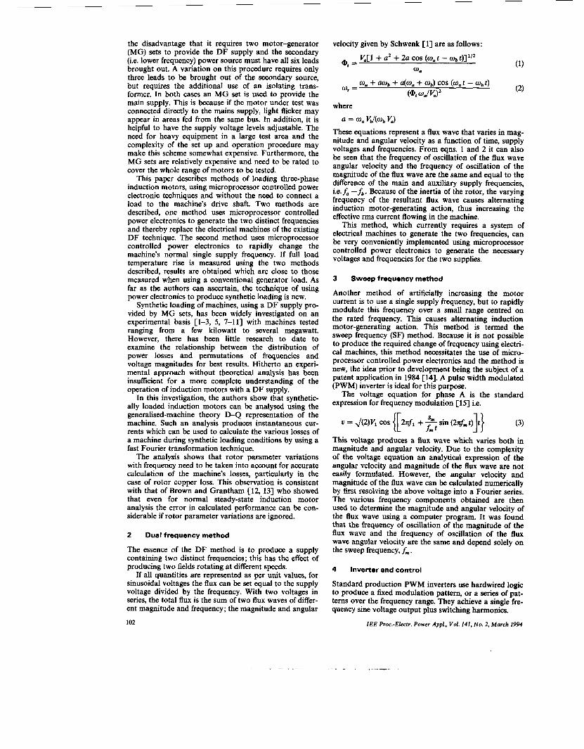
Fig. 1 double-cage rotor 000 leakage reactmce A A A resistance
Variations of rotor parameters for a laboratory machine with a
output in real time by sine table lookups and multiplica- tion. This system is not constrained by hard wired logic. The software may be changed to produce output wave- forms other than simple sine functions.
A simple modulator calculates A sin (ot) for modula- tion, where A and o are variable. If dual frequency output is required then it is simply necessary to calculate A sin (oat) + B sin ( o b t ) where o, and ob are the required angular frequencies and A and B are the ampli- tudes. If sweep frequency output is required it is neces- sary to calculate A cos {[o, + ( B / o b t) sin (ob t)]t}. These calculations must be done in real time, which has recently become possible with microprocessor technology.
To implement the proposed methods described above, in the laboratory, the output stage of a standard 11 kW transistor inverter was interfaced with a Motorola 6809 microprocessor. Special control logic was designed around this microprocessor and programmable timers to produce the special inverter output required.
5 Synthetic loading analysis
5.1 0-0 axis representation A D, Q axis representation of the machine enables the performance of the synthetic loading method to be calcu- lated. The voltages applied to the D axis are as specified in the previous section for the DF and SF methods and the voltages applied to the Q axis are 90 degrees out of phase with these voltages. The differential equations for the various axis currents are then solved in the same way as for the conventionally supplied three-phase induction motor, only the instantaneous supply voltages are differ- ent.
5.2 Machine parameters The parameters of the induction motors were measured using the method of Grantham [13] which takes into account rotor parameter variations due to frequency (i.e. skin effect). The machine used in this investigation was a 415 V (A), 50 Hz, 7.5 kW, Cpole, 13.9 A, TEFC induc- tion motor. The rotor of this machine has a die-cast alu- minium double-cage structure. The per-phase parameters evaluated for the machine in ohms are R, = 1.89, XI = 5.58, R, = 2749 and X, = 159. The variations in R , and
IEE hoc.-Electr. Power Appl., Vol. 141, No. 2, March 1994
X2 with frequency (i.e. current displacement effect) are shown in Fig. 1.
To implement the parameter variations in the com- puter simulation program, it is desirable to determine how the rotor current frequency changes with the aux- iliary supply frequency,f,, in the DF method and sweep frequency, f,, in the SF method. To this end, the real rotor instantaneous currents (not referred to the stator side), for both the DF and SF methods, with different voltage control parameters, were analysed into a series of frequency components. The frequency spectrum shows that the frequency of the main component of the rotor currents is f, - f b for the DF method, and f,, for the SF method. This frequency, fa -& or f, , is hereafter termed the 'field oscillating frequency' becausef, - f b , orfm is the frequency of oscillation of the rotating magnetic field, as discussed in Sections 2 and 3. The total rotor copper losses are calculated by summing the rotor copper losses produced by each individual component of the rotor current.
6
6.1 Analysis of copper losses One of the most important factors in the design and operation of electric machines is the relation between the life of the insulation and the operating temperature of the machine. Consideration of induction machine losses is important because losses determine the heating of the machine, and therefore the temperature rise of the machine.
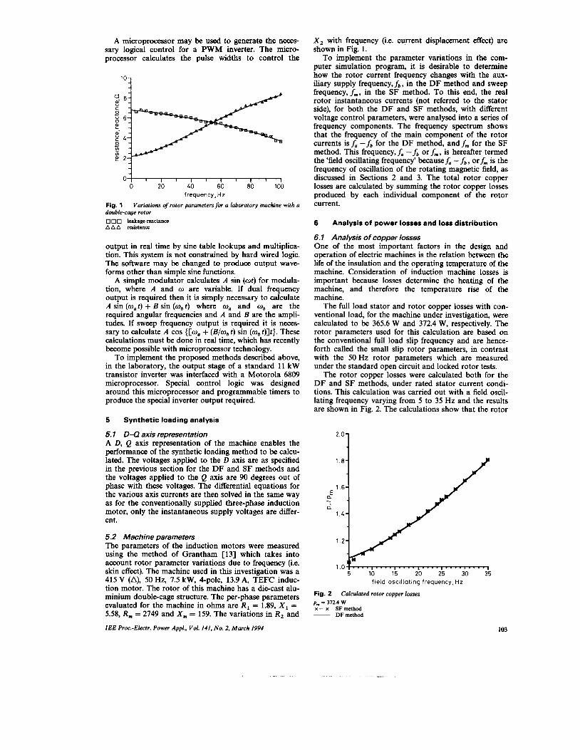
The full load stator and rotor copper losses with con- ventional load, for the machine under investigation, were calculated to be 365.6 W and 372.4 W, respectively. The rotor parameters used for this calculation are based on the conventional full load slip frequency and are hence- forth called the small slip rotor parameters, in contrast with the 50Hz rotor parameters which are measured under the standard open circuit and locked rotor tests.
The rotor copper losses were calculated both for the D F and SF methods, under rated stator current condi- tions. This calculation was carried out with a field oscil- lating frequency varying from 5 to 35 Hz and the results are shown in Fig. 2. The calculations show that the rotor
copper losses are practically the same with both of the synthetic loading methods and increase almost linearly with the field oscillating frequency. In all cases the rotor copper losses are greater than for the conventional load condition; approximately 5% greater at 5 Hz and 80% greater at 35 Hz. Therefore for a better representation of rotor copper loss, a small value of field oscillating fre- quency should be used.
The reason for the larger rotor copper losses with the DF and SF methods is that the frequency of the main rotor current component is equal to the field oscillating frequency, which is always larger than the rotor fre- quency under the conventional load condition. A large field oscillating frequency increases the degree of skin effect in the rotor conductors and therefore rotor copper losses are also increased.
Although skin effect is generally not as large in the stator winding as it is in the rotor, particularly where the rotor has been specifically designed for high starting torque, it nevertheless can be significant, particularly for large machines; for this reason 50Hz values of stator resistance, measured from a Ware [16] test, rather than DC values of resistance are always used in the analysis.
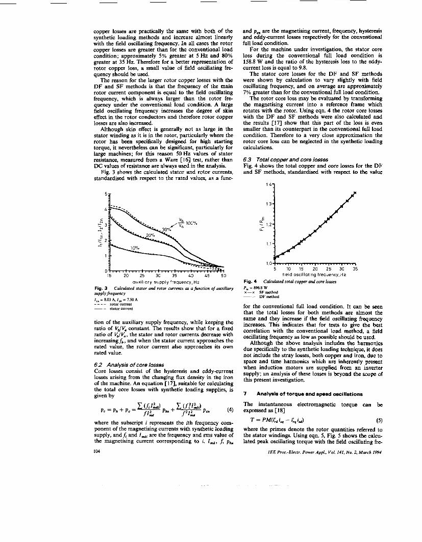
Fig. 3 shows the calculated stator and rotor currents, standardised with respect to the rated values, as a func-
auxiliary supply frequency, Hz Fig. 3 Calculated stator and rotor currents as a function of auxiliary s w l y f r e q w w I , , 3 8.03 A, I , . = 7.50 A _ _ _ - rotor current __ stator current
tion of the auxiliary supply frequency, while keeping the ratio of VJV. constant. The results show that for a fixed ratio of v,lV,, the stator and rotor currents decrease with increasingh, and when the stator current approaches the rated value, the rotor current also approaches its own rated value.
6.2 Analysis of core losses Core losses consist of the hysteresis and eddy-current losses arising from the changing flux density in the iron of the machine. An equation [17], suitable for calculating the total core losses with synthetic loading supplies, is given by
where the subscript i represents the ith frequency com- ponent of the magnetising currents with synthetic loading supply, andA and I,, are the frequency and rms value of the magnetising current corresponding to i. I,, f, p,,,,
104
and pen are the magnetising current, frequency, hysteresis and eddy-current losses respectively for the conventional full load condition.
For the machine under investigation, the stator core loss during the conventional full load condition is 158.8 W and the ratio of the hysteresis loss to the eddy- current loss is equal to 9.8.
The stator core losses for the DF and SF methods were shown by calculation to vary slightly with field oscillating frequency, and on average are approximately 7% greater than for the conventional full load condition.
The rotor core loss may be evaluated by transforming the magnetising current into a reference frame which rotates with the rotor. Using eqn. 4 the rotor core losses with the D F and SF methods were also calculated and the results 1171 show that this part of the loss is even smaller than its counterpart in the conventional full load condition. Therefore to a very close approximation the rotor core loss can be neglected in the synthetic loading calculations.
6.3 Total copper and core losses Fig. 4 shows the total copper and core losses for the DF and SF methods, standardised with respect to the value
‘“1 1.34
1.04-i 5 10 15 20 25 30 35
field oscillating frequency, Hz Fig. 4 P,” = 896.8 w x-x SFmcthcd __ DFmcthod
Calculated total copper and core losses
for the conventional full load condition. It can be seen that the total losses for both methods are almost the same and they increase if the field oscillating frequency increases. This indicates that for tests to give the best correlation with the conventional load method, a field oscillating frequency as low as possible should be used.
Although the above analysis includes the harmonics due specifically to the synthetic loading technique, it does not include the stray losses, both copper and iron, due to space and time harmonics which are inherently present when induction motors are supplied from an inverter supply; an analysis of these losses is beyond the scope of this present investigation.
7
The instantaneous electromagnetic torque can be expressed as [ 181
Analysis of torque and speed oscillations
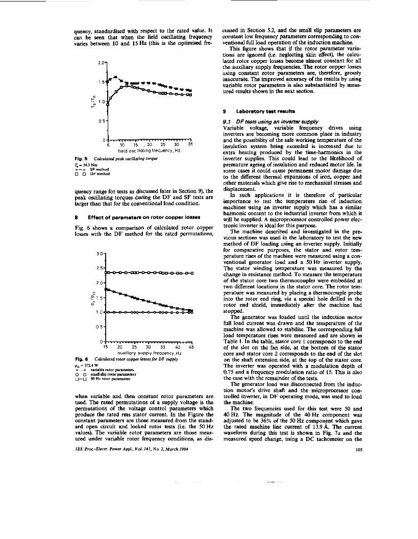
(5) where the primes denote the rotor quantities referred to the stator windings. Using eqn. 5, Fig. 5 shows the calcu- lated peak oscillating torque with the field oscillating fre-
IEE hoc.-Electr. Power Appl., Vol. 141, No. 2, March 1994
quency, standardised with respect to the rated value. It can be seen that when the field oscillating frequency varies between 10 and 15 Hz (this is the optimised fre-
0.51
O m 5 field oscillating frequency, Hz
Fig. 5 T - 54.3 Nm x-x SFmethod 0-0 DFmethod
Calculated peak oscillaring torque
quency range for tests as discussed later in Section 9), the peak oscillating torques during the DF and SF tests are larger than that for the conventional load condition.
8 Effect of parameters on rotor copper losses
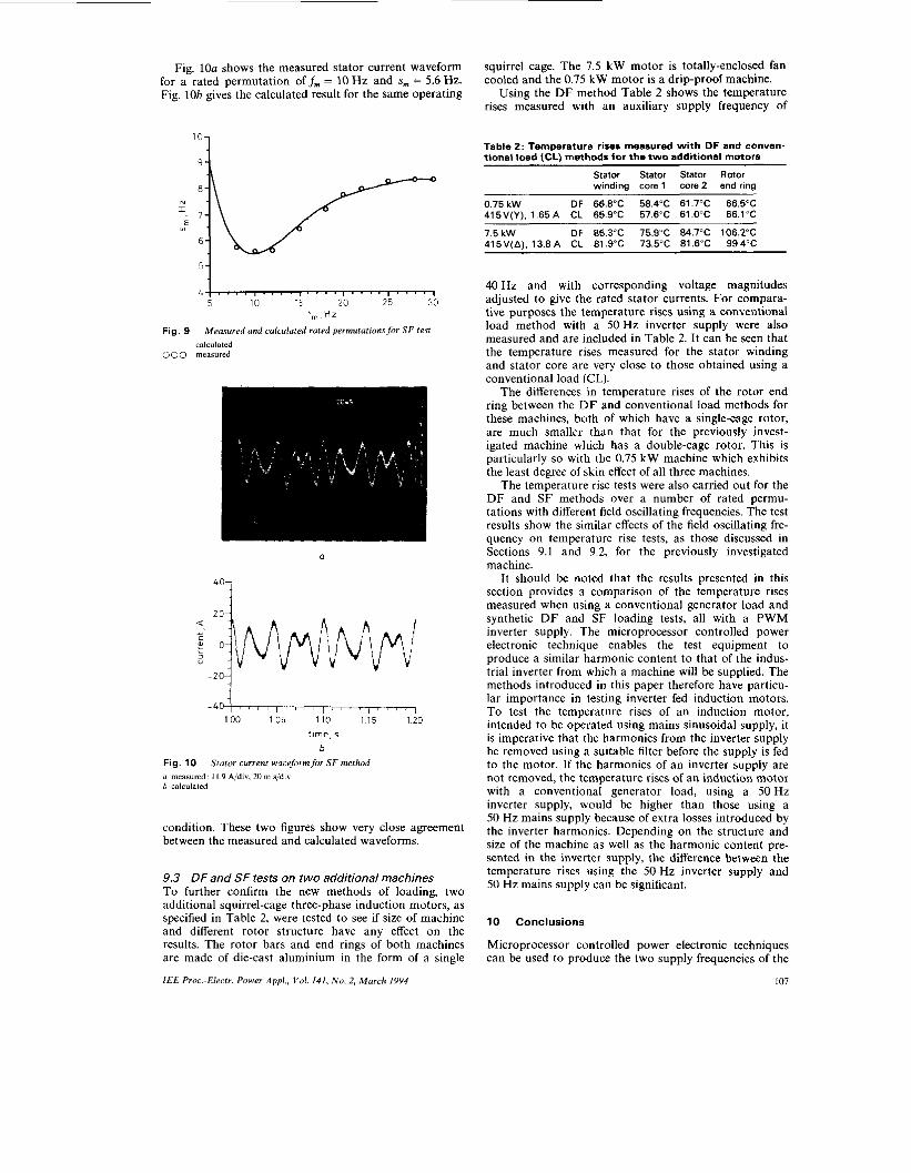
Fig. 6 shows a comparison of calculated rotor copper losses with the DF method for the rated permutations,
3.0-1
1.5 a
1.0
0.51
0 15 20 25 30 35 40 45
auxiliary supply frequency, Hz Fig. 8 p , = 312.4 W x- x variable rotor parameters 0-0 small dip rotor puamcbrs D-0 M Hz rotor parameten
Calculated rotor copper lossesfor DF supply
when variable and then constant rotor parameters are used. The rated permutations of a supply voltage is the permutations of the voltage control parameters which produce the rated rms stator current. In the Figure the constant parameters are those measured from the stand- ard open circuit and locked rotor tests (i.e. the 50 Hz values). The variable rotor parameters are those meas- ured under variable rotor frequency conditions, as dis-
IEE Proc.-Electr. Power Appl., Vol. 141, No. 2, March 1994
cussed in Section 5.2, and the small slip parameters are constant low frequency parameters corresponding to con- ventional full load operation of the induction machine.
This figure shows that if the rotor parameter varia- tions are ignored (i.e. neglecting skin effect), the calcu- lated rotor copper losses become almost constant for all the auxiliary supply frequencies. The rotor copper losses using constant rotor parameters are, therefore, grossly inaccurate. The improved accuracy of the results by using variable rotor parameters is also substantiated by meas- ured results shown in the next section.
9 Laboratory test results
9.1 DF tests using an inverter supply Variable voltage, variable frequency drives using inverters are becoming more common place in industry and the possibility of the safe working temperature of the insulation system being exceeded is increased due to extra heating produced by the time-harmonics in the inverter supplies. This could lead to the likelihood of premature ageing of insulation and reduced motor life. In some cases it could cause permanent motor damage due to the different thermal expansions of iron, copper and other materials which give rise to mechanical stresses and displacement.
In such applications it is therefore of particular importance to test the temperature rise of induction machines using an inverter supply which has a similar harmonic content to the industrial inverter from which it will be supplied. A microprocessor controlled power elec- tronic inverter is ideal for this purpose.
The machine described and investigated in the pre- vious sections was used in the laboratory to test the new method of DF loading using an inverter supply. Initially for comparative purposes, the stator and rotor tem- perature rises of the machine were measured using a con- ventional generator load and a 50Hz inverter supply. The stator winding temperature was measured by the change in resistance method. To measure the temperature of the stator core two thermocouples were embedded at two different locations in the stator core. The rotor tem- perature was measured by placing a thermocouple probe into the rotor end ring, via a special hole drilled in the rotor end shield, immediately after the machine had stopped.
The generator was loaded until the induction motor full load current was drawn and the temperature of the machine was allowed to stabilise. The corresponding full load temperature rises were measured and are shown in Table 1. In the table, stator core 1 corresponds to the end of the slot on the fan side, at the bottom of the stator core and stator core 2 corresponds to the end of the slot on the shaft extension side, at the top of the stator core. The inverter was operated with a modulation depth of 0.75 and a frequency modulation ratio of 15. This is also the case with the remainder of the tests.
The generator load was disconnected from the induc- tion motor's drive shaft and the microprocessor con- trolled inverter, in DF operating mode, was used to load the machine.
The two frequencies used for this test were 50 and 40 Hz. The magnitude of the 40 Hz component was adjusted to be 36% of the 50 Hz component which gave the rated machine line current of 13.9A. The current waveform during this test is shown in Fig. 7a and the measured speed change, using a DC tachometer on the
105
drive shaft of the test machine, was 1365 to 1551 rev/min. those from a conventional load test. The results will Fig. 7b gives the calculated stator current waveform for therefore always be on the safe side and thereby the same operating condition. It can be seen that the cab introduce an additional factor of safety which is often the
case in the standards which specify the various methods of protection for electrical equipment in hazardous atmospheres.
While the microprocessor controlled DF test referred to above was carried out at specific frequencies and volt- ages, there are a large number of permutations of fre- quencies and voltage magnitudes which are capable of producing rated stator current. Laboratory tests were carried out to establish some of these permutations and when compared with the caculated results, they show very good agreement as shown in Fig. 8. The tests carried
P
'OI 2 0
- 4 0 1 8 8 8 r ' 8 r r ~ I I I N 1 8 71 1'00 165 110 115 1 2 0
t1rne.s
b Fig. 7 a measured I I 9 A/div. 20 rn aidw h calculated
Stator current waveform for DF method
culated waveform is in very good agreement with the measured one.
The corresponding stator and rotor temperature rises were measured and are included in Table 1. These results
Table 1 : Temperature rises measured wi th conventional load (CL) and DF methods -
Stator winding Stator core 1 Stator core 2 Rotor end ring
(except for the rotor end ring) are very close to, and slightly higher than, the results using a SO Hz inverter supply with a conventional generator load. The slightly higher temperature rises of the stator winding and stator core with the DF method are partly due to the increased stator core loss and partly due to the increased rotor copper loss as discussed in Section 6.
The temperature rise measured for the rotor shows an increase of 16.4"C with the DF method compared with the conventional load method. The higher temperalure rise of the rotor end ring is mainly due to increased skin effect with the DF supply, in which the frequency of the main rotor current component is 10 Hz for this particular test. Consequently for applications where the rotor tem- perature is very important, such as Ex e and Ex N motors for hazardous atmospheres, it should be noted that the DF method results will always be higher than
-2
?O
>
0 15 20 25 30 35 40 45
f b , H z Fig. 8
~ calculated 000 measured
Measured and calculated rated permutationsfor DF test
out for these rated permutations show that the tem- peratures rises of the stator winding and stator core, when the auxiliary supply frequency varies between about 40 and 35 Hz, are very close to, and slightly higher than, those obtained with the conventional load test using a 50 Hz inverter supply. The difference in tem- perature rises between the two methods becomes large when the auxiliary supply frequency reduces below about 35 Hz. Tests with auxiliary supply frequencies greater than 40 Hz were not performed because the readings of the measuring instruments became unstable, thus reducing the accuracy with which they could be read.
The results and observations made for the DF test method will be further substantiated on two additional machines discussed later in Section 9.3.
9.2 SF tests using an inverter supply The SF method, with a centre frequency of 50 Hz, was next used to fully load the same induction motor. A modulation depth of 0.75 and a frequency modulation ratio of 15 was also used for this test.
The test results show that at the same field oscillating frequency, the temperature rises measured for both the DF and SF methods are very close to one another. This indicates that the sweep frequency method can be used as an alternative way for testing the temperature rise of induction machines and a sweep frequency of about 10 to 15 Hz should be used for the best test results.
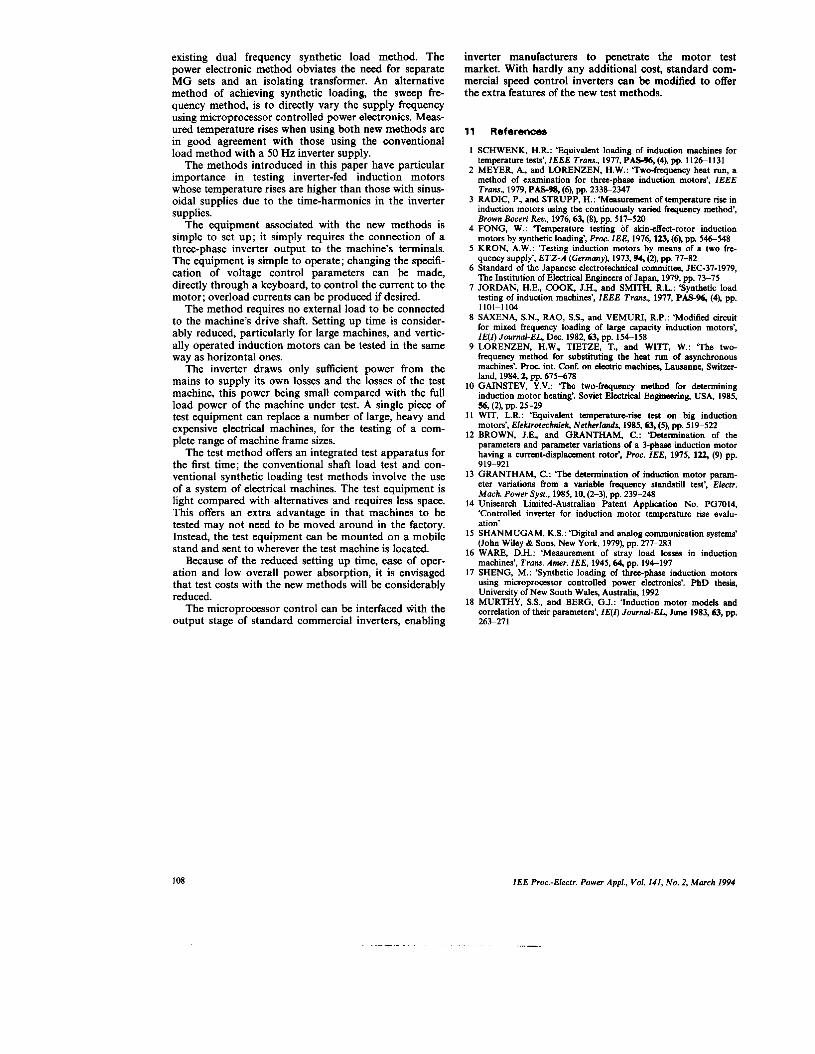
Fig. 9 gives the measured and calculated permutations of sweep frequencies and sweep magnitudes which are capable of producing the rated stator current. Corre- lation between the calculated and measured results are very good.
106 I E E Proc.-Elrctr. Power Appl . , Vol. 141, N o . 2, M a r c h 1994
Fig. 10a shows the measured stator current waveform for a rated permutation off, = 10 Hz and s, = 5.6 Hz. Fig. 10b gives the calculated result for the same operating
l 0 1
N r i
Fig. 9
000
5 1 i t . . . . , . . . . I . . . . , . . . . I . . . . I 5 10 15 20 25 30
f,,Hz
Measured and calculated rated permutations for S F test calculated measured
Fig. 10 Stator current waveformfiw S F method LI measured I I 9 Aidw, 20 m s/div h calculated
condition. These two figures show very close agreement between the measured and calculated waveforms.
9.3 DF and SF tests on two additional machines To further confirm the new methods of loading, two additional squirrel-cage three-phase induction motors, as specified in Table 2, were tested to see if size of machine and different rotor structure have any effect on the results. The rotor bars and end rings of both machines are made of die-cast aluminium in the form of a single
I E E Proc.-Electr. Power Appl., Vol . 141, N o . 2, March 1994
squirrel cage. The 7.5 kW motor is totally-enclosed fan cooled and the 0.75 kW motor is a drip-proof machine.
Using the DF method Table 2 shows the temperature rises measured with an auxiliary supply frequency of
Table 2: Temperature rises measured wi th DF and conven- tional load (CL) methods for the t w o additional motors
Stator Stator Stator Rotor winding core 1 core 2 end ring
40 Hz and with corresponding voltage magnitudes adjusted to give the rated stator currents. For compara- tive purposes the temperature rises using a conventional load method with a 50 Hz inverter supply were also measured and are included in Table 2. It can he seen that the temperature rises measured for the stator winding and stator core are very close to those obtained using a conventional load (CL).
The differences in temperature rises of the rotor end ring between the DF and conventional load methods for these machines, both of which have a single-cage rotor, are much smaller than that for the previously invest- igated machine which has a double-cage rotor. This is particularly so with the 0.75 kW machine which exhibits the least degree of skin effect of all three machines.
The temperature rise tests were also carried out for the DF and SF methods over a number of rated permu- tations with different field oscillating frequencies. The test results show the similar effects of the field oscillating fre- quency on temperature rise tests, as those discussed in Sections 9.1 and 9.2, for the previously investigated machine.
It should be noted that the results presented in this section provides a comparison of the temperature rises measured when using a conventional generator load and synthetic D F and SF loading tests, all with a PWM inverter supply. The microprocessor controlled power electronic technique enables the test equipment to produce a similar harmonic content to that of the indus- trial inverter from which a machine will be supplied. The methods introduced in this paper therefore have particu- lar importance in testing inverter fed induction motors. To test the temperature rises of an induction motor, intended to be operated using mains sinusoidal supply, it is imperative that the harmonics from the inverter supply be removed using a suitable filter before the supply is fed to the motor. If the harmonics of an inverter supply are not removed, the temperature rises of an induction motor with a conventional generator load, using a 50Hz inverter supply, would be higher than those using a 50 Hz mains supply because of extra losses introduced by the inverter harmonics. Depending on the structure and size of the machine as well as the harmonic content pre- sented in the inverter supply, the difference between the temperature rises using the 50 Hz inverter supply and 50 Hz mains supply can be significant.
10 Conclusions
Microprocessor controlled power electronic techniques can be used to produce the two supply frequencies of the
I07
existing dual frequency synthetic load method. The power electronic method obviates the need for separate MG sets and an isolating transformer. An alternative method of achieving synthetic loading, the sweep fre- quency method, is to directly vary the supply frequency using microprocessor controlled power electronics. Meas- ured temperature rises when using both new methods are in good agreement with those using the conventional load method with a 50 Hz inverter supply.
The methods introduced in this paper have particular importance in testing inverter-fed induction motors whose temperature rises are higher than those with sinus- oidal supplies due to the time-harmonics in the inverter supplies.
The equipment associated with the new methods is simple to set up; it simply requires the connection of a three-phase inverter output to the machine’s terminals. The equipment is simple to operate; changing the specifi- cation of voltage control parameters can be made, directly through a keyboard, to control the current to the motor; overload currents can be produced if desired.
The method requires no external load to be connected to the machine’s drive shaft. Setting up time is consider- ably reduced, particularly for large machines, and vertic- ally operated induction motors can be tested in the same way as horizontal ones.
The inverter draws only sufficient power from the mains to supply its own losses and the losses of the test machine, this power being small compared with the full load power of the machine under test. A single piece of test equipment can replace a number of large, heavy and expensive electrical machines, for the testing of a com- plete range of machine frame sizes.
The test method offers an integrated test apparatus for the first time; the conventional shaft load test and con- ventional synthetic loading test methods involve the use of a system of electrical machines. The test equipment is light compared with alternatives and requires less space. This offers an extra advantage in that machines to be tested may not need to be moved around in the factory. Instead, the test equipment can be mounted on a mobile stand and sent to wherever the test machine is located.
Because of the reduced setting up time, ease of oper- ation and low overall power absorption, it is envisaged that test costs with the new methods will be considerably reduced.
The microprocessor control can be interfaced with the output stage of standard commercial inverters, enabling
inverter manufacturers to penetrate the motor test market. With hardly any additional cost, standard com- mercial speed control inverters can be modified to offer the extra features of the new test methods.
11 References
1 SCHWENK, H.R.: ‘Equivalent loading of induction machines for temperature tests’, I E E E Trans., 1977, PAS-%, (4). pp. 1126-1131
2 MEYER, A., and LORENZEN, H.W.: Two-frequency heat run, a method of examination for three-phase induction motors’, IEEE Trans., 1979, PAS-%, (a), pp. 2338-2347
3 RADIC, P., and STRUPP, H.: ‘Measurement of temperature rise in induction motors using the continuously varied frequency method‘, Brown floueri Rar., 1976,63, (a), pp. 517-520
4 FONG, W.: ‘Temperature testing of skin-cffect-rotor induction motors by synthetic loading’, Proc. IEE, 1976,123, (6), pp. 546-548
5 KRON, A.W.: Testing induction motors by means of a two fre- quency supply’, ETZ-A (Germany), 1973.94, (2). pp. 77-82
6 Standard of the Japanese electrotechid committee, JEC-37-1979, The Institution of Electrical Engineers of Japan, 1979, pp. 73-75
7 JORDAN, H.E., COOK, J.H., and SMITH, R.L.: ‘Synthetic load testing of induction machines’, IEEE Trans., 1977, PAS-96, (4), pp. 1101-1104
8 SAXENA, S.N., RAO, S.S., and VEMURI, R.P.: ‘Modified circuit for mixed freauencv loadinn of lame cauacitv induction motors’. IE(I) JournabEL, D&. 1982,-63, pp. i54-li8
frequency method for substituting the heat run of asynchronous machines’. Proc. int. Conf. on electric machines, Lausanne, Switzer- land, 1984,2, pp. 675-678
IO GAINSTEV, Y.V.: The two-frequency method for determining induction motor heating’. Soviet Electrical Enginaring, USA, 1985, s6, f2), PP. 25-29
11 WIT, L.R.: ‘Equivalent tcmpcraturOrisc test on big induction motors’, Elektrotcchniek. Netherlands 1985.63, (5), pp. 519-522
12 BROWN, J.E., and GRANTHAM, C.: ‘D*errmn ‘ ation of the parameters and parameter variations of a 3-phase induction motor having a currentdisplawnent rotor’, Proc. IEE, 1975, 122, (9) pp. 9 19-92 1
13 GRANTHAM, C.: ’The determination of induction motor param- eter variations from a variable frequency standstill test’, Elecn. Mach. Power Syst., 1985, 10, (2-3), pp. 239-248
14 Unisearch Limited-Australian Patent Application No. PG7014, ‘Controlled inverter for induction motor temperature rise evalu- ation’
15 SHANMUGAM, K.S.: ‘Digital and analog communication systems’ (John Wiley & Sons, New York, 1979), pp. 277-283
16 WARE, D.H.: ‘Measurement of stray load losses in induction machines’, Trans. Amer. IEE, 1945,64, pp. 194-197
17 SHENG, M.: ‘Synthetic loading of three-phase induction motors using microproassor controlled power electronics’. PhD thesis, University of New South Wales, Australia, 1992
18 MURTHY, S.S., and BERG, G.J.: ‘Induction motor models and correlation of their parameters’, IE(0 JournaI-EL, June 1983.63, pp. 263-271
108
. ,. ” .
I E E Proc.-Electr. Power Appl. , Vol. 141, No. 2, March 1994