A software design is a meaningful engineering representation of some software product that is to be built. A design can be traced to the customer's requirements and can be assessed for quality against predefined criteria. During the design process the software requirements model is transformed into design models that describe the details of the • data structures, • system architecture, • interfaces, and • components.
6. System Design What is Design? It is representation of something that is to be built. Example Designs in Real Life • Blue prints for a building architecture – Manifests in the actual building • A plan for conducting a workshop/conference – Workshop is executed as per the plan • Course Syllabus – Course is taught to cover the syllabus Analysis vs Design For all practical purposes, if we view analysis as "what" and design as "how" then they are equivalent operations that cannot be separated from each other. Term design is used in two ways a noun and a verb • Verb: represents the process of design • Noun: represents result of the design process – Design of an existing system – Design of a system to be constructed – Plan for a solution Software Design • creates a representation or model of the software. • is done before system is implemented. • is the intermediate language between requirements and code. • activity begins with a analyzed set of requirements . • determines major characteristics of a system. • Software design deals with transforming the customer requirements, as described in the SRS document, into a form (a set of documents) that is suitable for implementation in a programming language.
Transcript
6. System Design What is Design? It is representation of something that is to be built.
Example Designs in Real Life • Blue prints for a building architecture
– Manifests in the actual building • A plan for conducting a workshop/conference
– Workshop is executed as per the plan • Course Syllabus
– Course is taught to cover the syllabus
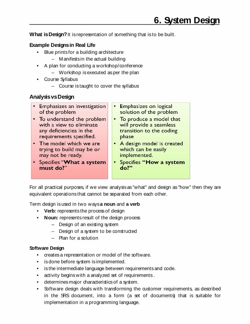
Analysis vs Design
For all practical purposes, if we view analysis as "what" and design as "how" then they are equivalent operations that cannot be separated from each other.
Term design is used in two ways a noun and a verb • Verb: represents the process of design • Noun: represents result of the design process
– Design of an existing system – Design of a system to be constructed – Plan for a solution
Software Design • creates a representation or model of the software. • is done before system is implemented. • is the intermediate language between requirements and code. • activity begins with a analyzed set of requirements . • determines major characteristics of a system. • Software design deals with transforming the customer requirements, as described
in the SRS document, into a form (a set of documents) that is suitable for implementation in a programming language.
A software design is a meaningful engineering representation of some software product that is to be built. A design can be traced to the customer's requirements and can be assessed for quality against predefined criteria. During the design process the software requirements model is transformed into design models that describe the details of the
• data structures, • system architecture, • interfaces, and • components.
Each design product is reviewed for quality (i.e., identify and correct errors, inconsistencies, or omissions) before moving to the next software engineering action.
The goal of software design is to transform the requirements specified in the SRS document into a structure suitable for implementation in some programming language.
During Design, developers – Define the design goals of project – Decompose the system into smaller subsystems – Select strategies for building the system such as hardware/software platform on
which the system will run. – Handle boundary conditions
Result of System design is a model that includes a – clear description of each of these strategies, – a subsystem decomposition, – a UML deployment diagram representing the hardware/software mapping of the
system
Design activities can be broadly classified into two important parts: • Preliminary (or high-level) design and • Detailed design.
Preliminary and detailed design activities The meaning and scope of two design activities (i.e. high-level and detailed design) tend to vary considerably from one methodology to another. High-level design means identification of different modules and the control
relationships among them and the definition of the interfaces among these modules.
The outcome of high-level design is called the program structure or software architecture. Many different types of notations have been used to represent a high-level design.
A popular way is to use a tree-like diagram called the structure chart to represent the control hierarchy in a high-level design.
During detailed design, the data structure and the algorithms of the different modules are designed.
The outcome of the detailed design stage is usually known as the module-specification document.
Design Process At the first level, i.e., Architectural Design, we decide the modules needed for the system, their specifications, and how modules should be interconnected, etc. In the second level, i.e., Logic Design, we decide the internal design of the modules.
Architectural Design • Establishing the overall structure of the software system. • Forms the largest part of the design activity • Specifies
– What components are needed for the system? – Specifies the behavior of the components – How components should be interconnected? – Defines how the system should be structured?
- Data Store at the center - Client Software accesses central repository
2. Data-flow Architecture - input data is to be transformed through a series of computational components
into output data - has set of components called filters, connected by pipes to transmit data from one
component to next
Design Process
Architectural/System Design Logic Design
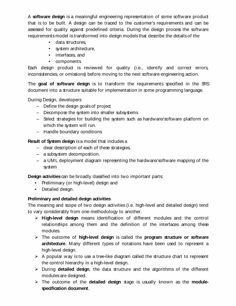
3. Main program/subprogram Architecture - Structure decomposes function
into a control hierarchy where a “main” program invokes a no. of program components
4. Layered Architecture
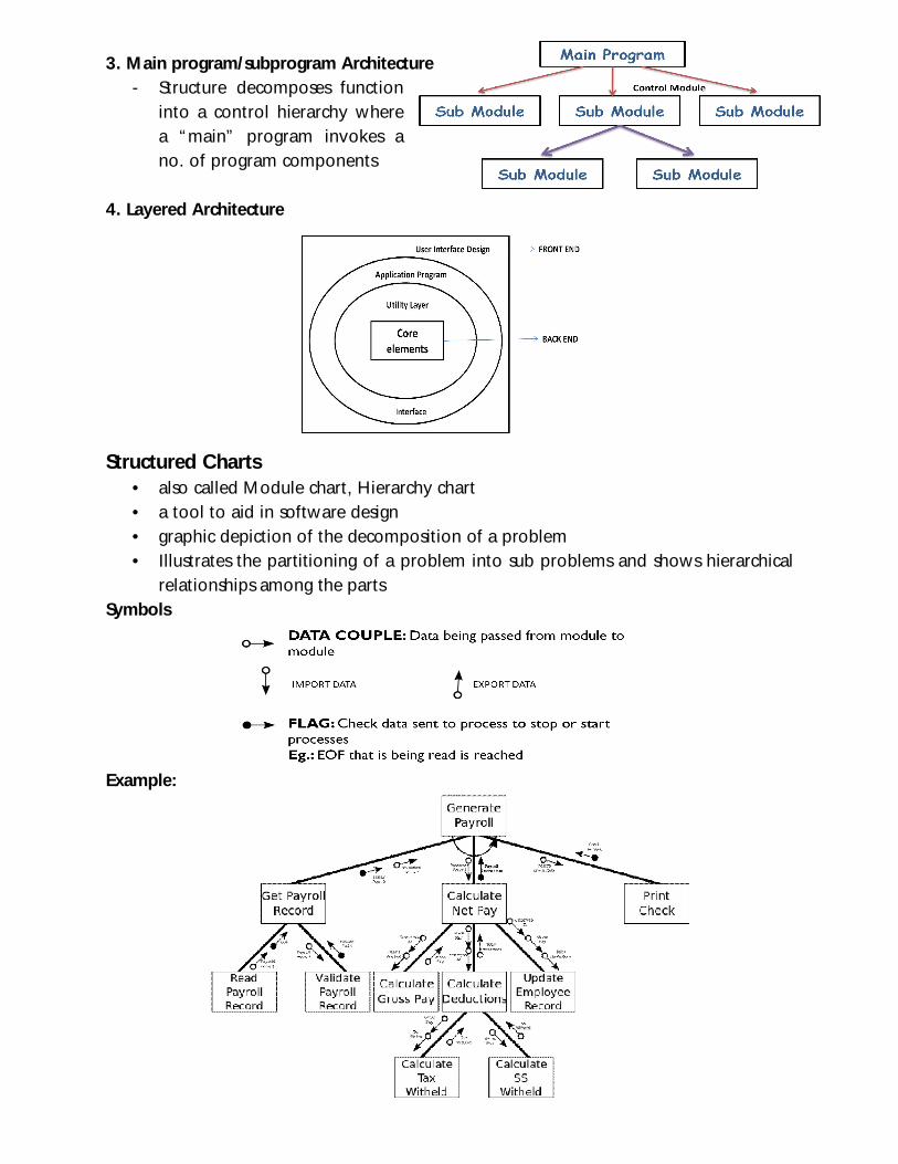
Structured Charts • also called Module chart, Hierarchy chart • a tool to aid in software design • graphic depiction of the decomposition of a problem • Illustrates the partitioning of a problem into sub problems and shows hierarchical
relationships among the parts Symbols
Example:
Design Principles Two fundamental principles in the design process are: 1. Problem Partitioning:
• Basic Principle “Divide and conquer” • Divide the problem into manageably small pieces
– Each piece can be solved separately – Each piece can be modified separately – Pieces can be related to the application
• Pieces cannot be independent; they must communicate
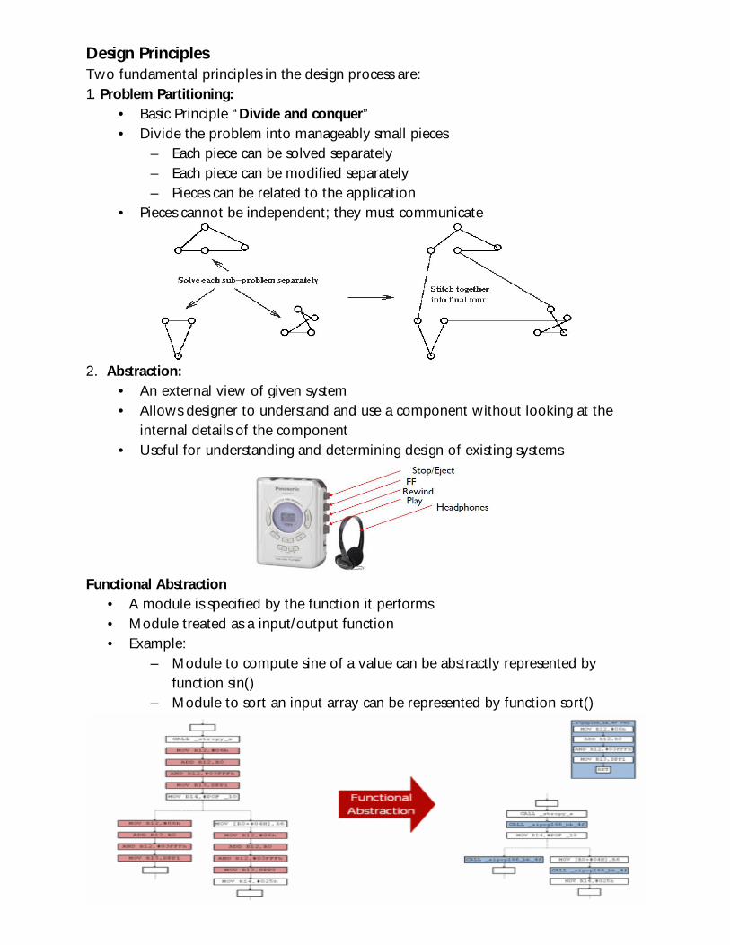
2. Abstraction:
• An external view of given system • Allows designer to understand and use a component without looking at the
internal details of the component • Useful for understanding and determining design of existing systems
Functional Abstraction
• A module is specified by the function it performs • Module treated as a input/output function • Example:
– Module to compute sine of a value can be abstractly represented by function sin()
– Module to sort an input array can be represented by function sort()
Logic Design • Components are designed to satisfy their specifications • How to implement components? • Algorithms for implementing components are designed • Each module’s responsibilities should be specified as precisely as possible
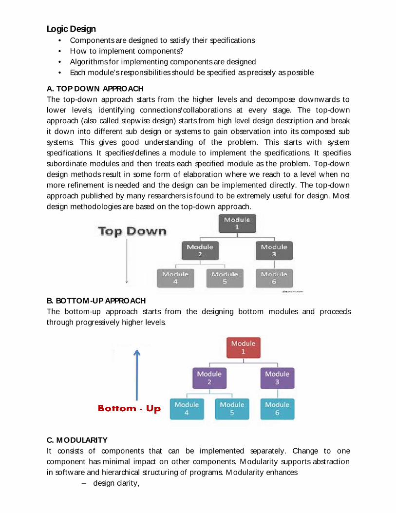
A. TOP DOWN APPROACH The top-down approach starts from the higher levels and decompose downwards to lower levels, identifying connections/collaborations at every stage. The top-down approach (also called stepwise design) starts from high level design description and break it down into different sub design or systems to gain observation into its composed sub systems. This gives good understanding of the problem. This starts with system specifications. It specifies/defines a module to implement the specifications. It specifies subordinate modules and then treats each specified module as the problem. Top-down design methods result in some form of elaboration where we reach to a level when no more refinement is needed and the design can be implemented directly. The top-down approach published by many researchers is found to be extremely useful for design. Most design methodologies are based on the top-down approach.
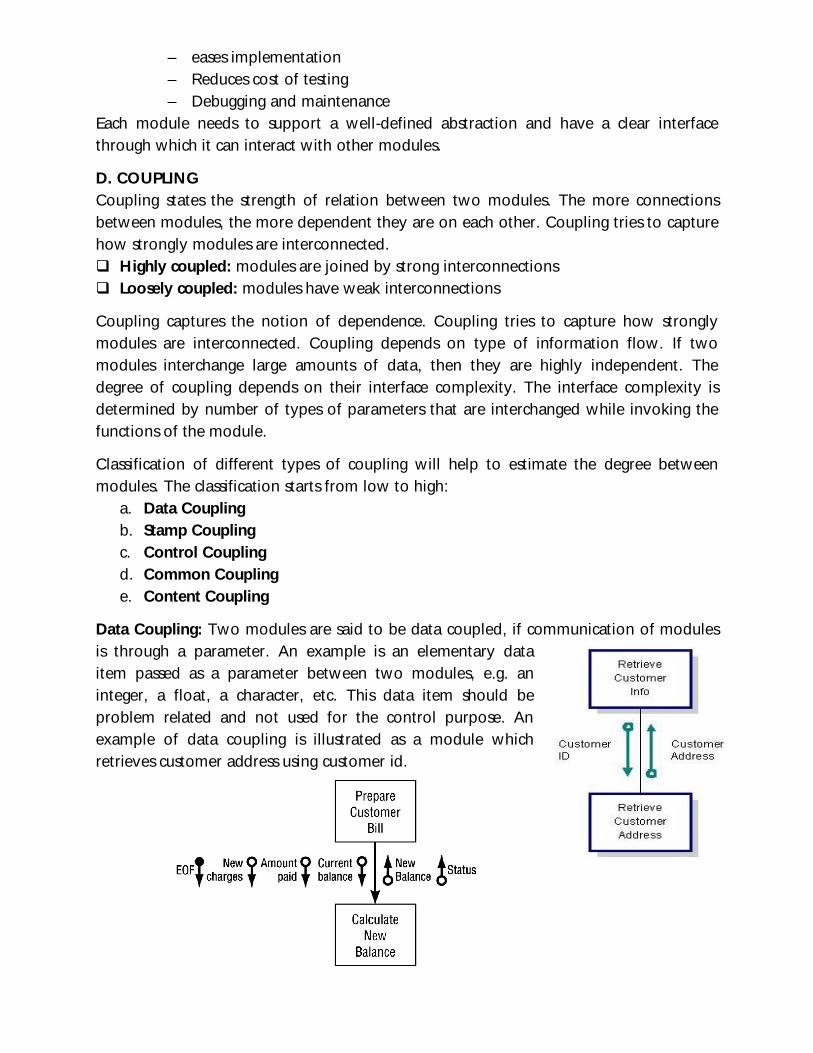
B. BOTTOM-UP APPROACH The bottom-up approach starts from the designing bottom modules and proceeds through progressively higher levels.
C. MODULARITY It consists of components that can be implemented separately. Change to one component has minimal impact on other components. Modularity supports abstraction in software and hierarchical structuring of programs. Modularity enhances
– design clarity,
– eases implementation – Reduces cost of testing – Debugging and maintenance
Each module needs to support a well-defined abstraction and have a clear interface through which it can interact with other modules.
D. COUPLING Coupling states the strength of relation between two modules. The more connections between modules, the more dependent they are on each other. Coupling tries to capture how strongly modules are interconnected. Highly coupled: modules are joined by strong interconnections Loosely coupled: modules have weak interconnections
Coupling captures the notion of dependence. Coupling tries to capture how strongly modules are interconnected. Coupling depends on type of information flow. If two modules interchange large amounts of data, then they are highly independent. The degree of coupling depends on their interface complexity. The interface complexity is determined by number of types of parameters that are interchanged while invoking the functions of the module.
Classification of different types of coupling will help to estimate the degree between modules. The classification starts from low to high:
a. Data Coupling b. Stamp Coupling c. Control Coupling d. Common Coupling e. Content Coupling
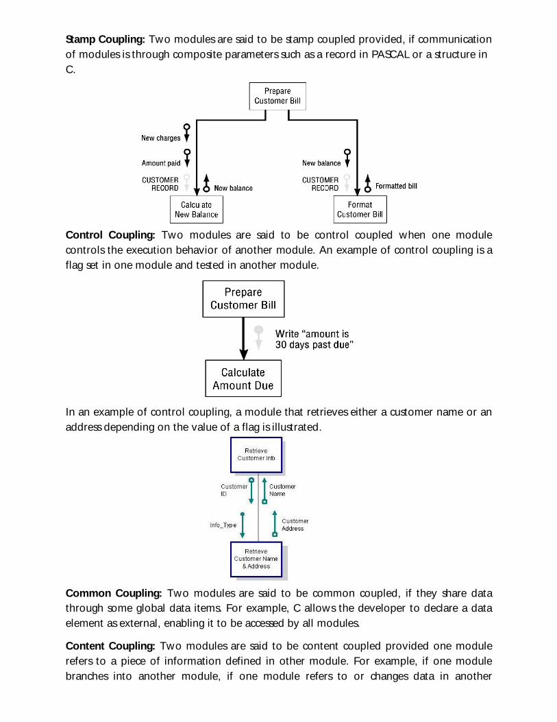
Data Coupling: Two modules are said to be data coupled, if communication of modules is through a parameter. An example is an elementary data item passed as a parameter between two modules, e.g. an integer, a float, a character, etc. This data item should be problem related and not used for the control purpose. An example of data coupling is illustrated as a module which retrieves customer address using customer id.
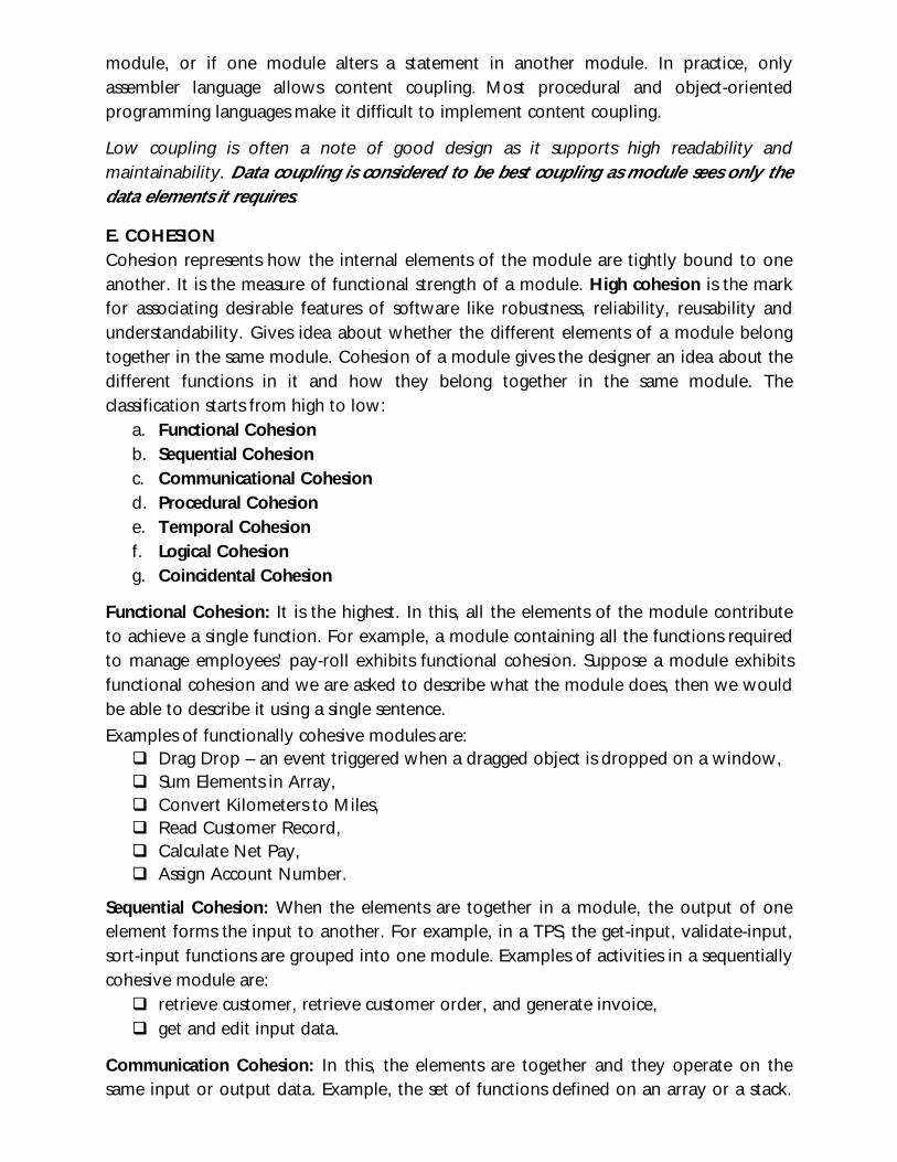
Stamp Coupling: Two modules are said to be stamp coupled provided, if communication of modules is through composite parameters such as a record in PASCAL or a structure in C.
Control Coupling: Two modules are said to be control coupled when one module controls the execution behavior of another module. An example of control coupling is a flag set in one module and tested in another module.
In an example of control coupling, a module that retrieves either a customer name or an address depending on the value of a flag is illustrated.
Common Coupling: Two modules are said to be common coupled, if they share data through some global data items. For example, C allows the developer to declare a data element as external, enabling it to be accessed by all modules.
Content Coupling: Two modules are said to be content coupled provided one module refers to a piece of information defined in other module. For example, if one module branches into another module, if one module refers to or changes data in another
module, or if one module alters a statement in another module. In practice, only assembler language allows content coupling. Most procedural and object-oriented programming languages make it difficult to implement content coupling.
Low coupling is often a note of good design as it supports high readability and maintainability. Data coupling is considered to be best coupling as module sees only the data elements it requires.
E. COHESION Cohesion represents how the internal elements of the module are tightly bound to one another. It is the measure of functional strength of a module. High cohesion is the mark for associating desirable features of software like robustness, reliability, reusability and understandability. Gives idea about whether the different elements of a module belong together in the same module. Cohesion of a module gives the designer an idea about the different functions in it and how they belong together in the same module. The classification starts from high to low:
a. Functional Cohesion b. Sequential Cohesion c. Communicational Cohesion d. Procedural Cohesion e. Temporal Cohesion f. Logical Cohesion g. Coincidental Cohesion
Functional Cohesion: It is the highest. In this, all the elements of the module contribute to achieve a single function. For example, a module containing all the functions required to manage employees’ pay-roll exhibits functional cohesion. Suppose a module exhibits functional cohesion and we are asked to describe what the module does, then we would be able to describe it using a single sentence.
Examples of functionally cohesive modules are: Drag Drop – an event triggered when a dragged object is dropped on a window, Sum Elements in Array, Convert Kilometers to Miles, Read Customer Record, Calculate Net Pay, Assign Account Number.
Sequential Cohesion: When the elements are together in a module, the output of one element forms the input to another. For example, in a TPS, the get-input, validate-input, sort-input functions are grouped into one module. Examples of activities in a sequentially cohesive module are: retrieve customer, retrieve customer order, and generate invoice, get and edit input data.
Communication Cohesion: In this, the elements are together and they operate on the same input or output data. Example, the set of functions defined on an array or a stack.
For example, obtain author, title, or price of book from bibliographic record, based on a passed flag.
Procedural Cohesion: In this, a module contains number of functions in which certain sequences have to be carried out for achieving an objective. Example, the algorithm for decoding a message. For example, a procedurally cohesive module may: write record A, read record A, format A for printing.
Temporal Cohesion: In this, elements of the module are executed in the same time span. One of the most common examples of a temporally cohesive module is an initialization routine that initializes data used by many modules throughout a system. The set of functions responsible for initialization, start-up, shutdown of some process, etc. exhibit temporal cohesion.
Logical Cohesion: It occurs if all the elements of a module have some logical relationship between them and perform similar operations. e.g. error handling, data input, data output, etc. An example of logical cohesion is the case where a set of print functions generating different output reports are arranged into a single module.
Coincidental Cohesion: It is the lowest. A module is said to be coincidental cohesive, if it performs set of tasks that relate to each other very loosely and functions put in are out of pure coincidence without any design. For example, in a transaction processing system (TPS), the get-input, print-error, and summarize-members functions are grouped into one module. The grouping does not have any relevance to the structure of the problem.
Functional Cohesion is considered to be best cohesion as modules are good candidates for re-use, are easily understood and easier to maintain.
For a good design: High Cohesion and Low coupling is the goal. A module with high cohesion and low coupling is said to be functionally independent of other modules i.e., cohesive module performs a single task or function and has minimal interaction with other modules. Functional independence is a sign to a good design as it reduces error propagation; reuse of a module becomes possible; and the complexity of the design is reduced.
Items developed during design phase Different modules required to implement the design solution. Control relationship among the identified modules. The interface among different modules identifies the exact data items
exchanged among the modules. Data structures of the individual modules. Algorithms required to implement each individual module.
Characteristics of good software Design The good quality product is obtained when we follow the design, which implements the desired requirements specified in software
• Correctness: – A good design should correctly implement all the functionalities identified
in the SRS document. • Understandability:
– A good design is easily understandable. • Efficiency:
– It should be efficient. • Maintainability:
– It should be easily amenable to change. Features of Design Document
• It should use consistent and meaningful names for various design components. • The design should be modular. The term modularity means that it should use a
cleanly decomposed set of modules. • It should neatly arrange the modules in a hierarchy, e.g. in a tree-like diagram.