9
Full Protection & Maintenance R GAS AND LIQUID - TURBIN FLOWMETER GAS AND LIQUID - TURBIN FLOWMETER Full Protection & Maintenance R SYS-FLOW GT

CORIOLIS MASS FLOWMETERCORIOLIS MASS FLOWMETER
Full Protection & Maintenance R
SYS-FLOWGAS AND LIQUID - TURBIN FLOWMETERGAS AND LIQUID - TURBIN FLOWMETER
Full Protection & Maintenance R
SYS-FLOW GT

1. High Accuracy: ±1%R, ±0.5%R, highest ±0.2%R optional
2. Good repeatability (short-term can reach 0.05%--0.2%)
3. Pulse frequency signal output with strong anti-interference capacity
4. High frequency (3-4 kHz) can be achieved with high resolution
5. Wide rangeability: medium or large diameters may reach 1:20 and small diameters are 1:10
6. Compact and light structure is convenient for installation and maintenance with high performance
7. Application to high pressure measurement
When the measured liquid flows through the sensor, as the vane is at a certain angle with flow direction, driving
torque to the vane wheel will be formed. After overcoming friction torque and flow resistance torque, the vane
wheel starts to rotate and the speed will turn stable after torque balance. In a certain condition, the speed of the
vane wheel is in direct proportion to the velocity. As the vane is magnetic conductive in magnetic field of signal
detector, the rotating vane periodically changes the magnetic flux of coil by cutting magnetic lines, in which way
pulse signal can be induced at coil end. The pulse signal will be sent to the display to show flow rate or total rate
after amplified by magnifier.
In a certain flow range, pulse frequency f is in direct proportion to liquid flow rate Q with equation as below:
In which
f is the pulse frequency
k is the instrument coefficient of sensor(1/m2), which shows in testing report. If coefficient in (1/L),
Q is flow rate of liquid under working status (m3/h or L/h)
The instrument coefficient is provided in manufacturer’s Testing Report and K value will be set in matching
display to show flow rate and total rate.
flow of liquids with kinematic viscosity under 5×10⁻⁶m2/s. It can be
widely used in the fields of Petrol, Chemical industry, Metallurgy, Scientific
research for measuring or control.
■ Working Principle
■ Features
■ Summary SLT Series Liquid Turbine Flowmeter is a kind of velocity instrument, which
composed of SLTi turbine Sensor and intelligent transmitter. The two
parts form in integrated model with features of compact structure,
direct and clear reading, high accuracy, good repeatability, high reliability
convenient installation/ maintenance / application etc.
SLTi model turbine flow sensor adapts to measure flow rate and total
SYSFLOW LIQUID TURBINE FLOWMETER

■ Power Supply: AC85-230V, 50/60Hz or DC24V or Battery (3 year)
■ Fluid temperature: -20℃~+120℃
■ Ambient condition: Temperature -10℃~+55℃, Relative Humidity 5%~90%
■ Accuracy: ±1.0%R(standard), ±0.5%R,±0.2% R
■ Output Signal: 4~20mA and Pulse (standard), 2-Relay Contact
■ Flange: JIS 10K RF Flange (standard), others
■ Protection Class: IP65(standard), ExdⅡBT6
Size(mm) Standard
range (m3/h)
Extended
range(m3/h)
Max. Working
Pressure (MPa)
Fluid
Temperature(℃)
Environment
Temperature(℃)
Mounting
Type
4 0.04-0.25 0.04-0.4
6.3
-20~+120 -20~+55
Screwed
6 0.1-0.6 0.06-0.6
10 0.2-1.2 0.15-1.5
15 0.6-6 0.4-8
20 0.8-8 0.4-8
25 1-10 0.5-10 6.3, 1.6(flange) Screwed,
Flanged
32 1.5-15 0.8-15 6.3, 1.6(flange) Screwed,
Flanged
40 2-20 1-20 6.3, 1.6(flange) Screwed,
Flanged
50 4-40 2-40
1.6 Flanged
65 7-70 4-70
80 10-100 5-100
100 20-200 10-200
125 25-250 13-250
150 30-300 15-300
200 80-800 40-800
■ Technical Data
■ Flow Range
SYSFLOW LIQUID TURBINE FLOWMETER

DN
(mm)
4
4mm, normal flow range 0.04-0.25m3/h, wide flow range 0.04-0.4m3/h
6 6mm, normal flow range 0.1-0.6m3/h, wide flow range 0.06-0.6m3/h
10 10mm, normal flow range 0.2-1.2m3/h, wide flow range 0.15-1.5m3/h
15 15mm normal flow range 0.6-6m3/h, wide flow range 0.4-8m3/h
20 20mm normal flow range 0.8-8m3/h, wide flow range 0.4-8m3/h
25 25mm normal flow range 1-10m3/h, wide flow range 0.5-10m3/h
32 32mm normal flow range 1.5-15m3/h, wide flow range 0.8-15m3/h
40 40mm normal flow range 2-20m3/h, wide flow range 1-20m3/h
50 50mm normal flow range 4-40m3/h, wide flow range 2-40m3/h
65 65mm normal flow range 7-70m3/h, wide flow range 4-70m3/h
80 80mm normal flow range 10-100m3/h, wide flow range 5-100m3/h
100 100mm normal flow range 20-200m3/h, wide flow range 10-200m3/h
125 125mm normal flow range 25-250m3/h, wide flow range 13-250m3/h
150 150mm normal flow range 30-300m3/h, wide flow range 15-300m3/h
200 200mm normal flow range 80-800m3/h, wide flow range 40-800m3/h
Type
N Basic type, 12-24V power, pulse output, high level≥8V, low level≤0.8V
A 4—20mA two wires current output, remote transmitting type
B Battery power supply, site display
C site display/4—20mA two wires current output + Pulse output
Accuracy 05 Accuracy class 0.5
10 Accuracy class 1.0
Material S 304 Stainless steel
L 316(L) Stainless steel
Explosion-proof No mark, non-explosion-proof
E Explosion-proof(ExdIIBT6)
■ Model Selection
Model Specification
SLTi ■ ■ ■ ■ ■ ■ Flow Sensor, Basic type, Pulse Output
SLT ■ ■ ■ ■ ■ ■ Flow Meter, Site display, Pulse+4~20mA output
SLTi-4~10 Sensor
SLTi-50 ~ 200 Sensor
SLTi-15 ~ 40 Sensor
SYSFLOW LIQUID TURBINE FLOWMETER
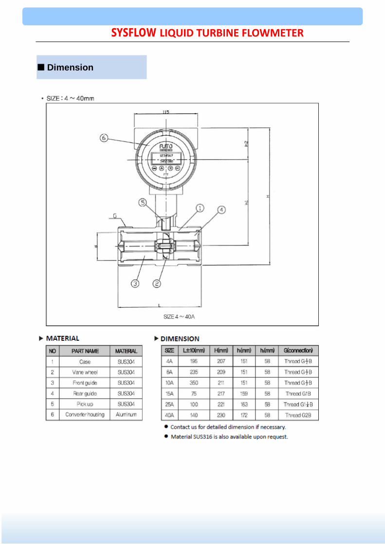
■ Dimension
SYSFLOW LIQUID TURBINE FLOWMETER

■ Dimension
SYSFLOW LIQUID TURBINE FLOWMETER

1. Wide measuring scope(Qmax/Qmin≥20:1), high precision, good repeatability, small pressure loss, low start
flow to 0.6m3/h.
2. Superior vane wheel supports stronger ability of shock-resistance, anti-electromagnetic disturbance and
anti-vibration. Sealed self-lubricating bearings with reliable performance and long service life are used.
3. Built-in pressure/temperature sensor brings high safety performance, compact structure and nice appearance.
4. The system with super low power consumption is adopted (Li-battery with 3.0V, 10AH can work 3 years at
least in continuous service). It has powerful functions, low power consumption, excellent performance and
intelligent display with non-linear accuracy compensation functions.
5. Meter parameters can be set on line with pushbuttons and can be displayed on the LCD screen. The LCD
screen is obvious and clear, and highly reliable.
6. Pressure compensation can be made under the conditions of stable pressure of the measured gas.
■ Summary
■ Working Principle
■ Features
SGT Series GAS Turbine Flowmeter is a kind of velocity instrument,
which is characteristic of high precision, good repeatability,
simple structure, wide measuring scope, compact volume, light
weight, small pressure loss, easy maintenance, etc. It can
be used widely in petroleum, chemical, metallurgical, urban gas
network industries and so on. In particular, it has been extensively
used for the metering of urban natural gas, coal gas, LPG
(liquefied petroleum gas), light hydrocarbon gas, etc. in
transmission and distribution network and the metering of gas
pressure regulating stations.
7. Perfect protection and explosionproof function. Protection class IP65 and explosionproof label ExiaⅡCT6Gb.
SGT Series Gas Turbine Flowmeter is designed to set the turbine in the gas flow to be measured and when
the gas flows through the flowmeter, the gas is rectified and accelerated under the function of the
rectifier in a special structure. As the vane is at a certain angle with flow direction, driving torque to the
vane wheel will be formed. After overcoming friction torque and flow resistance torque, the vane wheel starts
to rotate. In a certain flow rate scope, the angular speed of the vane wheel and the flow rate are
proportional. Pulse signal in direct proportion to the gas volumetric flow rate can be induced by using the
electromagnetic induction principle. The pulse signal is amplified, filtrated, trimmed and then sent to the
integrating instrument for calculation, together with the signal detected by the temperature/pressure
transducer. Meanwhile the volumetric flow rate and total flow of the gas will be displayed on the LCD screen
directly.
SYSFLOW GAS TURBINE FLOWMETER

1. Flow Range: m3/h
Note: In order to keep best performance, it is better to measure flow range of 20%~80% Qmax.
2. Accuracy: Class 1.0, Class 1.5
3. Ambient temperature: -20℃~+60℃
4. Medium temperature: -20℃~+80℃
5. Atmospheric pressure : 86KPa~106KPa
6. Relative humidity: 5%~95%
Model Size(mm) Flow range (m3/h) Working Pressure
(MPa) Mounting Type
Type
Without Basic type, Pulse Output
A Current Output
B Site Display
C Site Display + Current Output
D Temperature & Pressure Compensation Type
Diameter
40 40 mm
50 50 mm
80 80 mm
100 100mm
150 150 mm
200 200 mm
Sensor Material Stainless Steel
Vane Material ABS
■ Technical Data
■ Model Selection
SGT-40 40(1-1/2”) 3-60 4.0 Flanged, Screwed
SGT-50 50(2”) 5-100 4.0 Flanged
SGT-80 80(3”) 10-240 1.6 Flanged
SGT-100 100(4”) 12-360 1.6 Flanged
SGT-150 150(6”) 25-1000 1.6 Flanged
SGT-200 200(8”) 50-2500 1.6 Flanged
Model Specification SGT ■ ■
SYSFLOW GAS TURBINE FLOWMETER

Model Size(mm) L H K n d Bolt Pressure
Note: Diameter for sensors and integrated meter of same size is the same.
■ Dimension
Fig.1 With Temperature & Pressure Compensation Type
Fig.2 Without Temperature & Pressure Compensation Type
(MPa)
SGT-40 40(1-1/2”) 200 275 110 4 Ф18 M16×55 4.0
SGT-50 50(2”) 200 290 125 4 Ф18 M16×60 4.0
SGT-80 80(3”) 220 322 160 8 Ф18 M16×70 1.6
SGT-100 100(4”) 220 345 180 8 Ф18 M16×80 1.6
SGT-150 150(6”) 300 395 250 8 Ф23 M20×80 1.6
SGT-200 200(8”) 360 448 295 12 Ф23 M20×90 1.6
SYSFLOW GAS TURBINE FLOWMETER


