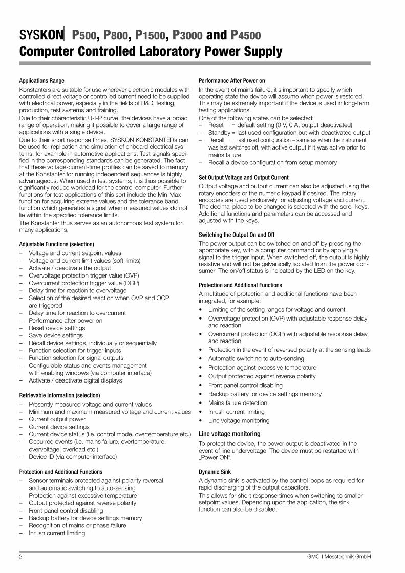
3-349-437-03 11/10.14 GMC-I Messtechnik GmbH SYSKONP500, P800, P1500, P3000 and P4500 Computer Controlled Laboratory Power Supply DAkkS Calibration Certificate as Standard Feature German Accreditation Body D-K-15080-01-01 SYSKON P3000 / P4500 SYSKON P500 / P800 / P1500 Description Series SYSKON (SYSTEM KONSTANTERs) are manual and remote controllable DC power supplies for laboratory and system use. Owing to the highest quality in switching controller technology, the devices are compact and lightweight despite their high output power. Active power factor control assures nearly sinusoidal mains input current. The floating output features “safety separation” from the mains input as well as from the computer interfaces, and is classified as a safety extra-low voltage circuit (SELV) in accordance with VDE / IEC. Wide ranging nominal output power values are available from output voltage and output current. The power output is voltage and current controlled with limiting to maximum withdrawable power. Transition to the control modes is automatic in accordance with the selected setpoints and load circumstances. The control loops are designed for short response times. An automatically activated, dynamic sink (can be disabled) provides for quick discharging of the output capacitors. Numerous protective functions and monitoring devices allow for ideal adaptation to actual conditions of use. Features The devices are generally equipped with a control panel and display, as well as an analog interface. One USB port and one RS 232 interface are provided as standard equipment for integration into computer controlled systems. The drivers for the USB port are provided as accessories on the included CD ROM. An optional IEEE 488 interface can be additionally installed, or ret- rofitted as an option, to connect and control programmable devices and to provide a standard interface for external communi- cation with the device. Manual adjustment of voltage and current is accomplished by means of two rotary encoders with selectable resolution, or with the numeric keypad. Numerous additional functions can be accessed via keys. Two digital LED displays (5 digit each) read out measured values and settings. LEDs indicate the current operating mode, selected display parameters and the status of device and interface func- tions. The analog interface makes it possible to adjust output voltage and current with the help of external control voltages. Monitor outputs read out an analog image of the voltage and current output quantities for further processing or additional displays. These control inputs and monitor outputs can also be used to couple several devices for master-slave operation with parallel or series connection. Two floating trigger inputs are available for controlling certain device functions. For example, they can be used to switch the output on and off, or to control sequences. Furthermore, three signal outputs are included at the analog inter- face, two of which are floating. These can be activated depending upon various functions, and can thus be used to control external devices or sequences. • Series SYSKON P500/P800/P1500: 500/800/1500 W output power SYSKON P3000/P4500 series: 3000 W/4500 W output power • Measuring functions for voltage, current and power with threshold memory (min & max values) • Minimal residual ripple and short response times • USB, RS232C Interface (standard) IEEE488 Interface (plug-in module option) • Integrated sequence function for the generation of voltage and current profiles with programmable sequence chain • Storage of 15 device configurations (setup memory) • Storage of 1700 sequence parameters • Output can be switched on and off • Operating functions can be protected • Master-slave operation is possible • Overvoltage, overcurrent and excessive temperature protection • Compact design, lightweight and minimal power loss thanks to switching controller technology • PC Software for remote control
Transcript
3-349-437-0311/10.14
GMC-I Messtechnik GmbH
SYSKONP500, P800, P1500, P3000 and P4500Computer Controlled Laboratory Power Supply
DAkkS Calibration Certificate as Standard Feature
GermanAccreditation BodyD-K-15080-01-01
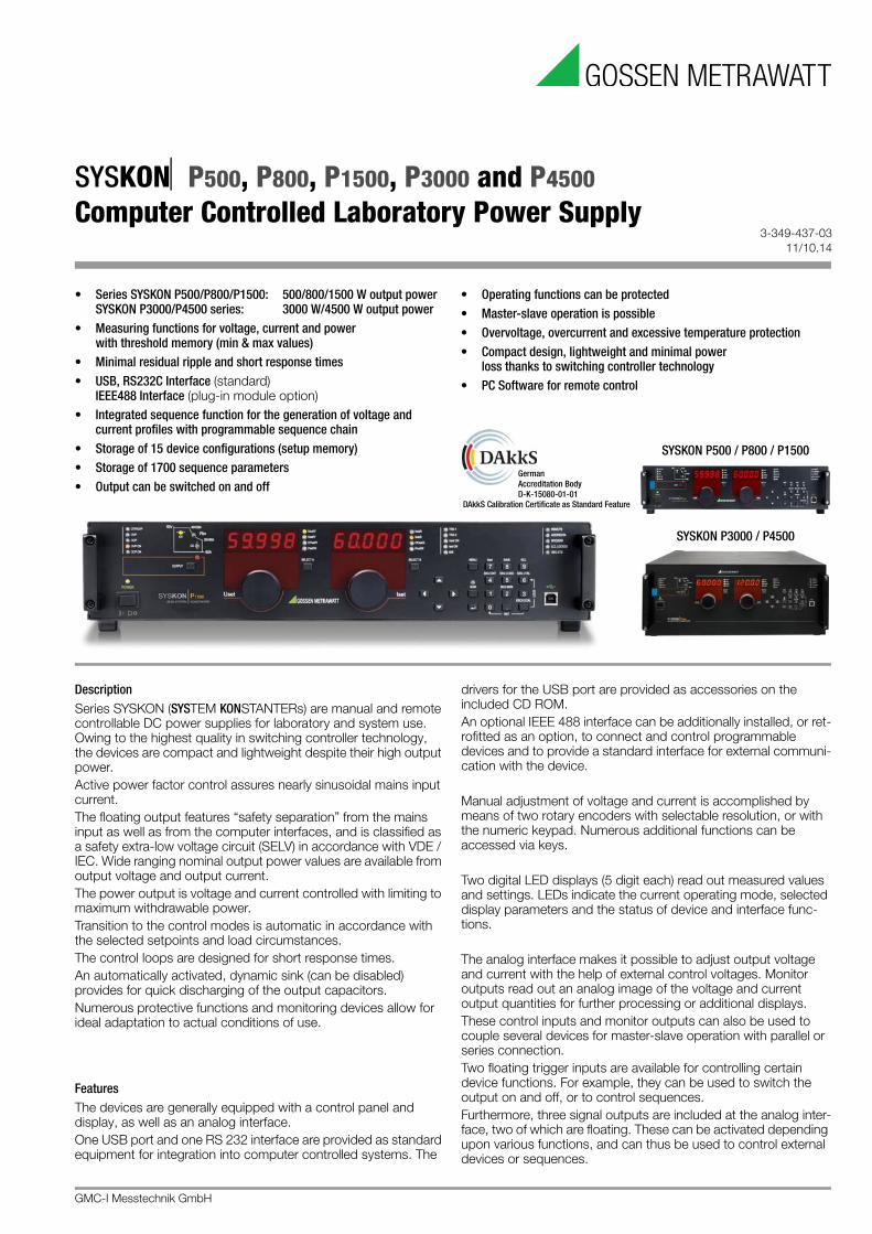
SYSKON P3000 / P4500
SYSKON P500 / P800 / P1500
DescriptionSeries SYSKON (SYSTEM KONSTANTERs) are manual and remote controllable DC power supplies for laboratory and system use. Owing to the highest quality in switching controller technology, the devices are compact and lightweight despite their high output power.Active power factor control assures nearly sinusoidal mains input current.The floating output features “safety separation” from the mains input as well as from the computer interfaces, and is classified as a safety extra-low voltage circuit (SELV) in accordance with VDE / IEC. Wide ranging nominal output power values are available from output voltage and output current. The power output is voltage and current controlled with limiting to maximum withdrawable power. Transition to the control modes is automatic in accordance with the selected setpoints and load circumstances.The control loops are designed for short response times. An automatically activated, dynamic sink (can be disabled) provides for quick discharging of the output capacitors.Numerous protective functions and monitoring devices allow for ideal adaptation to actual conditions of use.
FeaturesThe devices are generally equipped with a control panel and display, as well as an analog interface. One USB port and one RS 232 interface are provided as standard equipment for integration into computer controlled systems. The
drivers for the USB port are provided as accessories on the included CD ROM. An optional IEEE 488 interface can be additionally installed, or ret-rofitted as an option, to connect and control programmable devices and to provide a standard interface for external communi-cation with the device.
Manual adjustment of voltage and current is accomplished by means of two rotary encoders with selectable resolution, or with the numeric keypad. Numerous additional functions can be accessed via keys.
Two digital LED displays (5 digit each) read out measured values and settings. LEDs indicate the current operating mode, selected display parameters and the status of device and interface func-tions.
The analog interface makes it possible to adjust output voltage and current with the help of external control voltages. Monitor outputs read out an analog image of the voltage and current output quantities for further processing or additional displays.These control inputs and monitor outputs can also be used to couple several devices for master-slave operation with parallel or series connection.Two floating trigger inputs are available for controlling certain device functions. For example, they can be used to switch the output on and off, or to control sequences.Furthermore, three signal outputs are included at the analog inter-face, two of which are floating. These can be activated depending upon various functions, and can thus be used to control external devices or sequences.
• Series SYSKON P500/P800/P1500: 500/800/1500 W output powerSYSKON P3000/P4500 series: 3000 W/4500 W output power
• Measuring functions for voltage, current and power with threshold memory (min & max values)
• Minimal residual ripple and short response times• USB, RS232C Interface (standard)
IEEE488 Interface (plug-in module option)• Integrated sequence function for the generation of voltage and
current profiles with programmable sequence chain• Storage of 15 device configurations (setup memory)• Storage of 1700 sequence parameters• Output can be switched on and off
• Operating functions can be protected• Master-slave operation is possible• Overvoltage, overcurrent and excessive temperature protection• Compact design, lightweight and minimal power
loss thanks to switching controller technology• PC Software for remote control
SYSKONP500, P800, P1500, P3000 and P4500Computer Controlled Laboratory Power Supply
2 GMC-I Messtechnik GmbH
Applications RangeKonstanters are suitable for use wherever electronic modules with controlled direct voltage or controlled current need to be supplied with electrical power, especially in the fields of R&D, testing, production, test systems and training.Due to their characteristic U-I-P curve, the devices have a broad range of operation, making it possible to cover a large range of applications with a single device.Due to their short response times, SYSKON KONSTANTERs can be used for replication and simulation of onboard electrical sys-tems, for example in automotive applications. Test signals speci-fied in the corresponding standards can be generated. The fact that these voltage-current-time profiles can be saved to memory at the Konstanter for running independent sequences is highly advantageous. When used in test systems, it is thus possible to significantly reduce workload for the control computer. Further functions for test applications of this sort include the Min-Max function for acquiring extreme values and the tolerance band function which generates a signal when measured values do not lie within the specified tolerance limits.The Konstanter thus serves as an autonomous test system for many applications.
Adjustable Functions (selection)– Voltage and current setpoint values– Voltage and current limit values (soft-limits)– Activate / deactivate the output– Overvoltage protection trigger value (OVP)– Overcurrent protection trigger value (OCP)– Delay time for reaction to overvoltage– Selection of the desired reaction when OVP and OCP
are triggered– Delay time for reaction to overcurrent– Performance after power on– Reset device settings– Save device settings– Recall device settings, individually or sequentially– Function selection for trigger inputs– Function selection for signal outputs– Configurable status and events management
with enabling windows (via computer interface)– Activate / deactivate digital displays
Retrievable Information (selection)– Presently measured voltage and current values– Minimum and maximum measured voltage and current values– Current output power– Current device settings– Current device status (i.e. control mode, overtemperature etc.)– Occurred events (i.e. mains failure, overtemperature,
overvoltage, overload etc.)– Device ID (via computer interface)
Protection and Additional Functions– Sensor terminals protected against polarity reversal
and automatic switching to auto-sensing– Protection against excessive temperature– Output protected against reverse polarity– Front panel control disabling– Backup battery for device settings memory– Recognition of mains or phase failure– Inrush current limiting
Performance After Power onIn the event of mains failure, it’s important to specify which operating state the device will assume when power is restored. This may be extremely important if the device is used in long-term testing applications.One of the following states can be selected:– Reset = default setting (0 V, 0 A, output deactivated)– Standby = last used configuration but with deactivated output– Recall = last used configuration – same as when the instrument
was last switched off, with active output if it was active prior to mains failure
– Recall a device configuration from setup memory
Set Output Voltage and Output CurrentOutput voltage and output current can also be adjusted using the rotary encoders or the numeric keypad if desired. The rotary encoders are used exclusively for adjusting voltage and current. The decimal place to be changed is selected with the scroll keys. Additional functions and parameters can be accessed and adjusted with the keys.
Switching the Output On and OffThe power output can be switched on and off by pressing the appropriate key, with a computer command or by applying a signal to the trigger input. When switched off, the output is highly resistive and will not be galvanically isolated from the power con-sumer. The on/off status is indicated by the LED on the key.
Protection and Additional FunctionsA multitude of protection and additional functions have been integrated, for example:• Limiting of the setting ranges for voltage and current• Overvoltage protection (OVP) with adjustable response delay
and reaction• Overcurrent protection (OCP) with adjustable response delay
and reaction• Protection in the event of reversed polarity at the sensing leads• Automatic switching to auto-sensing• Protection against excessive temperature• Output protected against reverse polarity• Front panel control disabling• Backup battery for device settings memory• Mains failure detection• Inrush current limiting• Line voltage monitoring
Line voltage monitoringTo protect the device, the power output is deactivated in the event of line undervoltage. The device must be restarted with „Power ON“.
Dynamic SinkA dynamic sink is activated by the control loops as required for rapid discharging of the output capacitors.This allows for short response times when switching to smaller setpoint values. Depending upon the application, the sink function can also be disabled.
GMC-I Messtechnik GmbH 3
SYSKONP500, P800, P1500, P3000 and P4500Computer Controlled Laboratory Power Supply
Auto-SensingThe device can be switched to sensing mode operation (remote sensing) in order to compensate for voltage drop at the output leads. Sensing lead terminals are available to this end at the analog interface. If the (–) negative sensing terminal is connected to the negative load point, the device is automatically switched to sensing mode operation. Maximum compensatable voltage drop is 1 V per output lead.
Front Panel Control DisablingThe controls can be disabled to prevent unauthorized operation by pressing the appropriate key, with a computer command or by applying a signal to the trigger input.
Analog Control InputsVoltage and current can also be adjusted by via the control inputs at the analog interface. A 5 V signal corresponds to 100% of the respective nominal value.These inputs can be switched on and off using the keys, or with computer commands.The controlled output quantity is the sum of the digital setpoint value and the specified value at the control input.This function makes it possible to superimpose these control signals onto the output quantities.
Monitor OutputsThe actual values for output voltage and current can be acquired at the monitor outputs as a standardized signal (10 V corresponds to 100% nominal value).
Trigger InputsTwo floating trigger inputs are available for controlling device functions. The following trigger input assignments can be selected:– output = Switch the power output on and off– local lock = Disable controls– SQS = (sequence step) Step-by-step control of a
stored sequence– sequence = Start / stop the sequence function– Analog input = Activate / deactivate the analog control inputs
Signal OutputsProgrammable Control OutputsThe analog interface is equipped with three digital control outputs for status messages to external monitoring devices, for switching external components on and off, or for coupling purposes.The status of these outputs can be defined either directly, or depending upon the following device statuses:– Output on or off– Voltage or current regulation– Sequence function running or finished– SSET signal status for the sequence function– Limit value message for the measuring function (tolerance
band)
Min-Max Measured Value MemoryThe Min-Max function automatically acquires and saves minimum and maximum voltage and current values.
Tolerance Band (in combination with Min-Max function)Measured output values can be continuously compared with stored upper and lower tolerance band values. Evaluation is possible via the programmable control outputs.
MemoryThe memory function makes it possible to save and recall device configurations using a battery-backed memory module. The memory module is equipped with two storage areas:• Setup memory: 15 memory locations for complete
configurations• Sequence memory: 1700 memory locations for the following
sequence parameters:– voltage setpoint USET, – current setpoint ISET, – dwell time TSET– function request FSETwith the ability to invoke subsequences
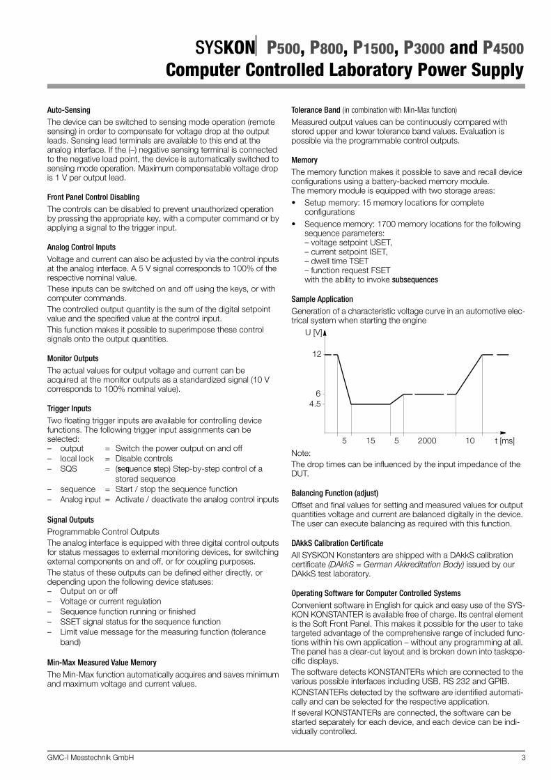
Sample ApplicationGeneration of a characteristic voltage curve in an automotive elec-trical system when starting the engine
Note: The drop times can be influenced by the input impedance of the DUT.
Balancing Function (adjust)Offset and final values for setting and measured values for output quantities voltage and current are balanced digitally in the device. The user can execute balancing as required with this function.
DAkkS Calibration CertificateAll SYSKON Konstanters are shipped with a DAkkS calibration certificate (DAkkS = German Akkreditation Body) issued by our DAkkS test laboratory.
Operating Software for Computer Controlled SystemsConvenient software in English for quick and easy use of the SYS-KON KONSTANTER is available free of charge. Its central element is the Soft Front Panel. This makes it possible for the user to take targeted advantage of the comprehensive range of included func-tions within his own application – without any programming at all. The panel has a clear-cut layout and is broken down into taskspe-cific displays.The software detects KONSTANTERs which are connected to the various possible interfaces including USB, RS 232 and GPIB.KONSTANTERs detected by the software are identified automati-cally and can be selected for the respective application.If several KONSTANTERs are connected, the software can be started separately for each device, and each device can be indi-vidually controlled.
U [V]
12
64.5
5 t [ms]15 5 2000 10
SYSKONP500, P800, P1500, P3000 and P4500Computer Controlled Laboratory Power Supply
OutputRegulator type Primary switched-mode regulatorOperating modes Adjustable constant voltage / constant cur-
rent source with automatic sharp transitionOutput isolation Floating output with “safe electrical
separation” from the mains input and computer interfaces
Allowable potential, output–ground Max. 240 V DC
Capacitance, output–ground (housing)SYSKON P500 typ. 1000 nFSYSKON P800 typ. 1SYSKON P1500 typically 1000 nFSYSKON P3000 typically 1000 nFSYSKON P4500 typically 1000 nF
GMC-I Messtechnik GmbH 5
SYSKONP500, P800, P1500, P3000 and P4500Computer Controlled Laboratory Power Supply
Analog InterfaceFunctions – Auto-sensing mode
– 2 programmable trigger inputs– 3 programmable signal outputs– Voltage control input (0 ... 5 V)– Current control input (0 ... 5 V)– Voltage monitor output (0 ... 10 V)– Current monitor output (0 ... 10 V)– Master-slave parallel operation– Master-slave series operation– Auxiliary power output: 15 V / 60 mA
Computer Interfaces
• IEC-625 / IEEE 488 interface (optional) • RS 232 interfaceTransmission mode Half-duplex, asynchronousTransmission speed 1200 to 115,200 baud, adjustable• USB portUSB port: 4-pin, type BUSB 1.1 compatible with USB 2.0Connector pin assignments 1: VCC, 2: D-, 3: D+, 4: GNDTransmission speed 9600 to 115,200 baud, adjustable
Power supplyLine voltage 115/230 V ~ + 10 / – 15%; 47 to 63 HzStarting current Max. 50 AS
Mains fuse SYSKON P500/P800/P1500: 1 x M15 A / 250 V (6.3 x 32 mm), ULSYSKON P3000/4500: 3 x M15 A/250 V
Electrical SafetySafety class IMeasuring category II for mains input
I for output and interfacesPollution degree 2Earth leakage current < 2.5 mARMSElectrical isolation Test voltageOutput – mains 2.2 kV ~Output – bus/ground 1.4 kV ~Mains – bus/ground 2.2 kV –Bus – ground No electrical isolation
Environmental ConditionsTemperature range Operation: 0 to 40 °C
Storage: –25 to +75 °CAtmospherichumidity Operation: 75% rel. humidity,
no condensation allowedStorage: 65% rel. humidity
Cooling With integrated fan(temperature controlled)Inlet vent: Side panelOutlet vent: Rear panel
Operating noise Noise pressure level at a distance of 30 cm with fan set to low / high Front 17 / 28 dBARear 22 / 32 dBALeft 17 / 28 dBARight 20 / 31 dBA
Electromagnetic CompatibilitySYSKON P500/P800/P1500Generic standard EN 61326-1: October 2006Interference emission EN 55022: class BInterference immunity EN 61000-4-2: feature A
EN 61000-4-3: feature BEN 61000-4-4: feature AEN 61000-4-5: feature AEN 61000-4-6: feature AEN 61000-4-8: feature AEN 61000-4-11: feature A
SYSKON P3000/4500Generic standard EN 61326-1: October 2006Interference emission EN 55022: class A *Interference immunity EN 61000-4-2: feature B
EN 61000-4-3: feature AEN 61000-4-4: feature BEN 61000-4-5: feature BEN 61000-4-6: feature AEN 61000-4-8: feature AEN 61000-4-11: feature B
* Note: Approved for the deployment in industrial environment. This device may cause radio interferences in domestic areas.
Applicated StandardsIEC 61010-1:2010, DIN EN 61010-1:2010, VDE 0411-1:2011EN 61326
Mechanical Data
Protection IP 00 for device and interface connectionsIP 20 for housing
Table Excerpt Regarding Significance of IP Codes
Design Benchtop device, suitable for installation to 19" cabinets
HE = standard height units
IP XY (1st char. X)
Protection against pene-tration by solid particles
IP XY (2nd char. Y)
Protection against penetration by water
0 Not protected 0 Not protected1 50.0 mm dia. 1 Vertical dripping2 12.5 mm dia. 2 Dripping (15 inclination)
Article No. Designation Dimensions (W x H x D) WeightK346A SYSKON
P500-060-03019" x 2 HE447 x 102 (88) x 541 (501) mm
10 kg
K347A SYSKON P800-060-040
19" x 2 HE447 x 102 (88) x 541 (501) mm
10 kg
K353A SYSKON P1500-060-060
19" x 2 HE447 x 102 (88) x 541 (501) mm
10 kg
K363A SYSKON P3000-060-120
19" x 4 HE447 x 191 (177) x 541 (501) mm
16 kg
K364A SYSKON P4500-060-180
19" x 4 HE447 x 191 (177) x 541 (501) mm
20 kg
K384A IEEE 488 interface (optional)
Approx. 0.14 kg
SYSKONP500, P800, P1500, P3000 and P4500Computer Controlled Laboratory Power Supply
6 GMC-I Messtechnik GmbH
Dimensional Drawing SYSKON P500 / P800 / P1500
447
465
482.6
501 40
8814
76.2
Installation position for optional interface IEEE-488 (material No. K384A)
All dimensions in millimeter
GMC-I Messtechnik GmbH 7
SYSKONP500, P800, P1500, P3000 and P4500Computer Controlled Laboratory Power Supply
Dimensional Drawing SYSKON P3000 / P4500
447
465
482.6
501 40
177
14
101.
6
Installation position for optional interface IEEE-488 (material No. K384A)
All dimensions in millimeter
SYSKONP500, P800, P1500, P3000 and P4500Computer Controlled Laboratory Power Supply
8 GMC-I Messtechnik GmbH
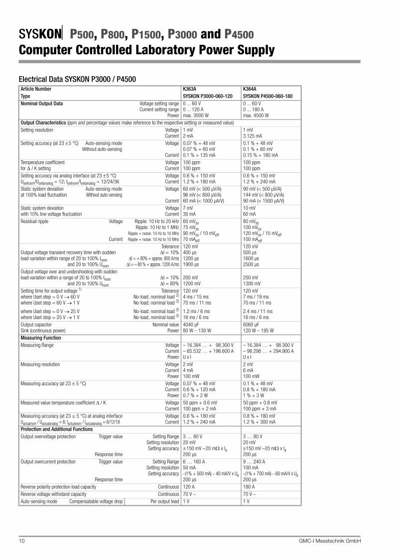
Electrical Data SYSKON P500 / P800 / P1500 Article Number K346A K347A K353AType SYSKON P500-060-030 SYSKON P800-060-040 SYSKON P1500-060-060Nominal Output Data Voltage setting range
Current setting rangePower
0 ... 60 V0 ... 30 Amax. 500 W
0 ... 60 V0 ... 40 Amax. 800 W
0 to 60 V0 to 60 AMax. 1500 W
Output Characteristics (ppm and percentage values make reference to the respective setting or measured value)Setting resolution Voltage
Measured value temperature coefficient / K VoltageCurrent
50 ppm + 0.4 mV 100 ppm + 1 mA
50 ppm + 0.4 mV 100 ppm + 1 mA
0.4 mV + 50 ppm 1 mA + 100 ppm
Measuring accuracy (at 23 ± 5 °C) at analog interfaceUactualnom / Uactualanalog = 6; Iactualnom / Iactualanalog = 6/12/18
VoltageCurrent
0.4 % + 120 mV0.5 % + 180 mA
0.4 % + 120 mV0.5 % + 180 mA
0.4 % + 120 mV1.2 % + 180 mA
Protection and Additional FunctionsOutput overvoltage protection Trigger value
Response time
Setting RangeSetting resolutionSetting accuracy
3 … 80 V 20 mV 150 mV –10 m x Ia 200 μs
3 … 80 V20 mV150 mV –20 m x Ia200 μs
3 to 80 V 20 mV 150 mV – 10 m x Ia 200 μs
Output overcurrent protection Trigger value
Response time
Setting RangeSetting resolutionSetting accuracy
1.5 … 40 A 20 mA –(1% + 350 mA) – 20 mA/V x Ua200 μs
2 … 53 A 20 mA –(1% + 350 mA) – 20 mA/V x Ua200 μs
3 to 80 A20 mA –(1% + 350 mA) – 20 mA/V x Ua200 μs
Reverse polarity protection load capacity Continuous 30 A 40 A 60 AReverse voltage withstand capacity Continuous 70 V – 70 V – 70 V –Auto-sensing mode Compensatable voltage drop Per output lead 1 V 1 V 1 V
GMC-I Messtechnik GmbH 9
SYSKONP500, P800, P1500, P3000 and P4500Computer Controlled Laboratory Power Supply
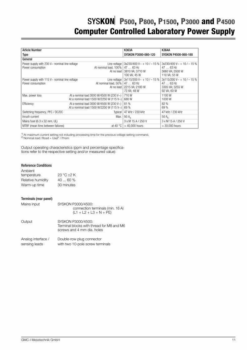
1) At maximum current setting not including processing time for the previous voltage setting command. 2) Nominal load: Rload = Uset² / Pnom
Output operating characteristics (ppm and percentage specifica-tions refer to the respective setting and/or measured value)
Reference ConditionsAmbienttemperature 23 °C 2 KRelative humidity 40 ... 60 %Warm-up time 30 minutes
115 V~ + 10 / – 15%, 47 to 63 Hz1125 VA; 1100 W55 VA; 36 W
Max. power loss At a nominal load 500 W/800 W/1500 W (230 V~)At a nominal load 500 W/800 W/750 W (115 V~)
150 W250 W
200 W350 W
365 W350 W
Efficiency At a nominal load 500 W/800 W/1500 W (230 V~)At a nominal load 500 W/800 W/750 W (115 V~)
77 %66 %
80 %70 %
80%68%
Switching frequency, PFC / DC/DC Typical 47 kHz / 230 kHz 47 kHz / 230 kHz 47 kHz / 230 kHzInrush current Max. 50 As 50 As 50 AsMains fuse (6.3 x 32 mm, UL) 1 x M 15 A / 250 V 1 x M 15 A / 250 V 1 x M 15 A / 250 VMTBF (mean time between failures) at 40 °C > 50,000 h > 50,000 h > 50,000 hours
Measured value temperature coefficient / K VoltageCurrent
50 ppm + 0.6 mV100 ppm + 2 mA
50 ppm + 0.8 mV100 ppm + 3 mA
Measuring accuracy (at 23 ± 5 °C) at analog interfaceUactualnom / Uactualanalog = 6; Iactualnom / Iactualanalog = 6/12/18
VoltageCurrent
0.6 % + 180 mV1.2 % + 240 mA
0.8 % + 180 mV1.2 % + 300 mA
Protection and Additional FunctionsOutput overvoltage protection Trigger value
Response time
Setting RangeSetting resolutionSetting accuracy
3 … 80 V20 mV150 mV –20 m x Ia200 μs
3 … 80 V20 mV150 mV –20 m x Ia200 μs
Output overcurrent protection Trigger value
Response time
Setting RangeSetting resolutionSetting accuracy
6 … 160 A50 mA–(1% + 500 mA) – 40 mA/V x Ua200 μs
9 … 240 A100 mA–(1% + 700 mA) – 60 mA/V x Ua 200 μs
Reverse polarity protection load capacity Continuous 120 A 180 AReverse voltage withstand capacity Continuous 70 V – 70 V –Auto-sensing mode Compensatable voltage drop Per output lead 1 V 1 V
GMC-I Messtechnik GmbH 11
SYSKONP500, P800, P1500, P3000 and P4500Computer Controlled Laboratory Power Supply
1) At maximum current setting not including processing time for the previous voltage setting command. 2) Nominal load: Rload = Uset² / Pnom
Output operating characteristics (ppm and percentage specifica-tions refer to the respective setting and/or measured value)
Reference ConditionsAmbient temperature 23 °C 2 KRelative humidity 40 ... 60 %Warm-up time 30 minutes
Max. power loss At a nominal load 3000 W/4500 W (230 V~)At a nominal load 1500 W/2250 W (115 V~)
710 W680 W
1100 W1030 W
Efficiency At a nominal load 3000 W/4500 W (230 V~)At a nominal load 1500 W/2250 W (115 V~)
81 %69 %
82 %69 %
Switching frequency, PFC / DC/DC Typical 47 kHz / 230 kHz 47 kHz / 230 kHzInrush current Max. 50 As 50 AsMains fuse (6.3 x 32 mm, UL) 3 x M 15 A / 250 V 3 x M 15 A / 250 VMTBF (mean time between failures) at 40 °C > 40,000 hours > 30,000 hours
Article Number K363A K364AType SYSKON P3000-060-120 SYSKON P4500-060-180
Edited in Germany • Subject to change without notice • A pdf version is available on the Internet
SYSKONP500, P800, P1500, P3000 and P4500Computer Controlled Laboratory Power Supply
• SYSKON P Konstanter• CD with user and driver software,
operating instructions (D + EN), data sheet (D + EN)• Clear-cut user software [soft front-panel]• Mains power cable (P500, P800, P1500)• USB cable (90° angle)• Installation set for 19" rack mounting• DAkkS calibration certificate• Operating instructions (printed)
Order Information
SoftwareFurther information regarding operating software and drivers is available for download on the internet:
www.gossenmetrawatt.com
Accessories
Manufacturer’s Guarantee
The SYSKON Konstanter is guaranteed for a period of 2 years after shipment. The manufacturer’s guarantee covers materials and workmanship. Damages resulting from use for any other than the intended purpose, as well as any and all consequential dam-ages, are excluded.Calibration is guaranteed for a period of 12 months.
Description (abbreviated name) Article NumberSYSKON P500-060-030 SYSTEM KONSTANTER K346A
SYSKON P800-060-040 SYSTEM KONSTANTER K347A
SYSKON P1500-060-060 SYSTEM KONSTANTER K353A
SYSKON P3000-060-120 SYSTEM KONSTANTER K363A
SYSKON P4500-060-180 SYSTEM KONSTANTER K364A
Option IEEE 488 interface for SYSKON KONSTANTER K384A
Description Note Article No.RS 232 bus cable, 2 m For connecting a device to an