44
System 8 System 8

System 8
System 8

S8–2
The name “System 8” stands for a modular system ofsolenoid coils, armature systems, solenoid operatorsand solenoid valves. The diameter of the armatures ofall valve components is approximately 8 mm. Thisvalue is the major characteristic of this type. Thecomponents' efficiency has been increased to the opti-mum in years of simulation, construction and practicaltesting.
APPLICATION OF SYSTEM 8
The solenoid operators and solenoid valves of system8 can be used for operating 2/2- or 3/2 way valves,especially in pneumatics. Available switching functionsare normally closed and normally open.
For 3/2 way valves of this series, typical maximumvalues for operating pressure and nominal orifice are 16bar/2.5 mm. 2/2 way solenoid operators and solenoidvalves can also be used for controlling liquids.
FUNCTION
While the solenoid operator/solenoid valve is de-energized, the armature1 is being pushed down on thelower valve seat3 by the reset spring2. The lower valveseat is closed by a sealing element4. In this switchposition the upper valve seat5 in the magnetic core isopen. When the valve is energized, the magnetic force
exceeds the force of the reset spring and moves thearmature into the opposite extreme position. In thiscase the upper valve seat5 is closed by the sealing ele-ment6, whereas the lower valve seat3 is open.
Solenoid operators and solenoid valves have identi-cal functionality. However, if solenoid operators are or-dered, neither the lower valve seat nor the valve body isshipped. Those components have to be provided by thecustomer.
2/2 way valves do not have an upper valve seat.Besides that, the function of the magnet is identical.

S8–3
SOLENOID COILWidth: 22 mmConnection type: industry formMoulding material: thermoset resin
General DataVoltage tolerance ··················································· ± 10 %Ambient temperature ············································· - 20 °C to + 50 °CRelative duty cycle ·················································· 100 %Insulation class of insulating materialsaccording to DIN VDE 0580 ···································· FDegree of protection with connectoraccording to EN 60529 ··········································· IP 65 (IP 67 possible with accessoires)Imprint ···································································· nass magnet (customer imprint possible)Protection class ······················································ I

S8–4
Technical Data Standard Versions
Part No. Voltage Frequency [Hz] Rated Power Power Level [K][W] [VA]
108-030-0048 024 V DC – 2,0 2 035
108-030-0862 110 V AC 50 4,1 2 050
108-030-0862 110 V AC 60 3,3 2 050
108-030-0798 230 V AC 50 3,9 2 050
108-030-0798 230 V AC 60 3,2 2 050
108-030-0050 024 V DC – 2,6 3 045
108-030-0052 024 V AC 50 6,0 3 075
108-030-0052 024 V AC 60 4,9 3 075
108-030-0049 220 V AC 50 6,0 3 075
108-030-0049 220 V AC 60 4,9 3 075
108-030-0051 230 V AC 50 6,0 3 075
108-030-0051 230 V AC 60 4,9 3 075
108-030-0043 012 V DC – 4,6 4 070
108-030-0043 024 V AC 50 7,1 4 090
108-030-0044 024 V DC – 4,8 4 070
108-030-0044 048 V AC 50 7,7 4 090
108-030-0047 220 V AC 50 8,5 4 095
108-030-0046 230 V AC 50 7,9 4 090
108-030-0046 230 V AC 60 6,4 4 090
108-030-0047 240 V AC 60 9,0 4 095
108-030-1169 012 V DC – 5,5 5 085
108-030-0045 024 V DC – 6,0 5 085
108-030-1169 024 V AC 50 9,2 5 105
108-030-0045 048 V AC 60 7,6 5 085
108-030-1120 230 V AC 50 9,4 5 102
[K]: steady-state over-temperature according to VDE 0580

S8–5
SOLENOID COILWidth: 22 mmConnection type: industry formMoulding material: thermoplastic
General DataVoltage tolerance ··················································· ± 10 %Ambient temperature ············································· - 20 °C to + 50 °CRelative duty cycle ·················································· 100 %Insulation class of insulating materialsaccording to DIN VDE 0580 ···································· FDegree of protection with connectoraccording to EN 60529 ··········································· IP 65Imprint ···································································· nass magnet (customer imprint possible)Protection class ······················································ I

S8–6
Technical Data Standard Versions
Part No. Voltage Frequency [Hz] Rated Power Power Level [K][W] [VA]
108-030-0278 024 V DC – 1,1 1 020
108-030-0273 024 V DC – 2,0 2 035
108-030-0279 024 V AC 50 3,6 2 050
108-030-0279 024 V AC 60 3,0 2 050
108-030-0268 110 V AC 50 4,1 2 050
108-030-0268 110 V AC 60 3,3 2 050
108-030-0276 220 V AC 50 3,9 2 050
108-030-0276 220 V AC 60 3,2 2 050
108-030-0294 230 V AC 50 3,9 2 050
108-030-0294 230 V AC 60 3,2 2 050
108-030-0271 012 V DC – 2,4 3 045
108-030-0275 024 V DC – 2,6 3 045
108-030-0260 048 V DC – 2,7 3 075
108-030-0260 110 V AC 50 6,0 3 075
108-030-0274 110 V DC – 3,6 3 075
108-030-0274 220 V AC 50 6,0 3 105
108-030-0281 230 V AC 50 6,0 3 075
108-030-0281 240 V AC 60 5,5 3 075
108-030-0257 012 V DC – 4,6 4 100
108-030-0257 024 V DC 50 7,1 4 100
108-030-0258 024 V DC – 4,8 4 070
108-030-0258 048 V AC 50 8,0 4 070
108-030-0259 048 V DC – 5,0 4 070
108-030-0267 110 V AC 50 8,6 4 100
108-030-0267 110 V AC 60 6,6 4 100
108-030-0261 220 V AC 50 9,3 4 105
108-030-0269 230 V AC 50 7,9 4 095
108-030-0269 230 V AC 60 6,4 4 099
108-030-0270 012 V AC 50 8,8 5 105
108-030-0264 024 V DC – 6,0 5 085
108-030-0263 024 V AC 50 9,3 5 110
108-030-0266 110 V AC 50 8,6 5 105
108-030-0286 110 V DC – 6,1 5 105
108-030-0266 120 V AC 60 8,7 5 105
108-030-0272 110 V DC – 4,9 5 105
108-030-0272 220 V AC 50 8,5 5 105
108-030-0287 220 V AC 50 8,0 5 105
108-030-0286 230 V AC 60 9,7 5 105
108-030-0298 220 V AC 50 8,0 5 105
108-030-0298 230 V AC 50 9,4 5 105
[K]: steady-state over-temperature according to VDE 0580
S8–7
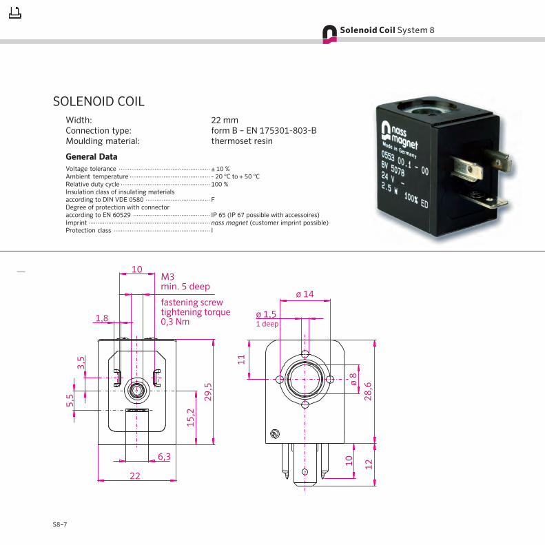
SOLENOID COILWidth: 22 mmConnection type: form B – EN 175301-803-BMoulding material: thermoset resin
General DataVoltage tolerance ··················································· ± 10 %Ambient temperature ············································· - 20 °C to + 50 °CRelative duty cycle ·················································· 100 %Insulation class of insulating materialsaccording to DIN VDE 0580 ···································· FDegree of protection with connectoraccording to EN 60529 ··········································· IP 65 (IP 67 possible with accessoires)Imprint ···································································· nass magnet (customer imprint possible)Protection class ······················································ I

S8–8
Technical Data Standard Versions
Part No. Voltage Frequency [Hz] Rated Power Power Level [K][W] [VA]
108-030-0524 024 V DC – 6,0 5 085
108-030-0524 048 V AC 60 7,6 5 085
108-030-0525 110 V AC 50 8,6 5 105
108-030-0525 120 V AC 60 8,7 5 105
[K]: steady-state over-temperature according to VDE 0580
S8–9
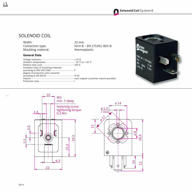
SOLENOID COILWidth: 22 mmConnection type: form B – EN 175301-803-BMoulding material: thermoplastic
General DataVoltage tolerance ··················································· ± 10 %Ambient temperature ············································· - 20 °C to + 50 °CRelative duty cycle ·················································· 100 %Insulation class of insulating materialsaccording to DIN VDE 0580 ···································· FDegree of protection with connectoraccording to EN 60529 ··········································· IP 65Imprint ···································································· nass magnet (customer imprint possible)Protection class ······················································ I

S8–10
Technical Data Standard Versions
Part No. Voltage Frequency [Hz] Rated Power Power Level [K][W] [VA]
108-030-0889 024 V DC – 1,7 2 035
108-030-0891 024 V DC – 2,6 3 045
108-030-0892 230 V AC 50 6,0 3 075
108-030-0892 230 V AC 60 4,9 3 075
108-030-0887 024 V DC – 4,8 4 070
108-030-0887 048 V AC 50 7,7 4 070
108-030-0890 110 V DC – 4,9 4 100
108-030-0890 220 V AC 50 8,5 4 100
108-030-0893 024 V AC 50 7,9 4 095
108-030-0893 024 V AC 60 6,4 4 095
108-030-0888 024 V DC – 6,0 5 085
108-030-0888 048 V AC 60 7,6 5 085
[K]: steady-state over-temperature according to VDE 0580

S8–11
Circuit Diagram
SOLENOID COILWidth: 22 mmConnection type: M 12 metal threadMoulding material: thermoset resin
General DataVoltage tolerance ··················································· ± 10 %Ambient temperature ············································· - 20 °C to + 50 °CRelative duty cycle ·················································· 100 %Insulation class of insulating materialsaccording to DIN VDE 0580 ···································· FDegree of protection with connectoraccording to EN 60529 ··········································· IP 65 (IP 67 on request)Imprint ···································································· nass magnet (customer imprint possible)Protection class ······················································ II

S8–12
Technical Data Standard Versions
Part No. Voltage Rated Power [W] Power Level [K] LED yellow
108-030-1109 24 V DC 2,5 3 45 x
108-030-0240 24 V DC 4,8 4 70 x
[K]: steady-state over-temperature according to VDE 0580

S8–13
SOLENOID COILWidth: 22 mmConnection type: flying leadsMoulding material: thermoplastic
General DataVoltage tolerance ··················································· ± 10 %Ambient temperature ············································· - 20 °C to + 50 °CRelative duty cycle ·················································· 100 %Insulation class of insulating materialsaccording to DIN VDE 0580 ···································· FDegree of protection ·············································· IP 65Imprint ···································································· nass magnet (customer imprint possible)Protection class ······················································ III

S8–14
Technical Data Standard Versions
Part No. Voltage Frequency [Hz] Rated Power Power Level [K] Length of Flying Leads
[W] [VA]
108-030-0788 024 V DC – 2,6 3 45 500 mm
108-030-0785 048 V DC – 2,7 3 45 500 mm
108-030-0784 024 V DC – 4,8 4 70 500 mm
108-030-0784 048 V AC 50 8,5 4 70 500 mm
108-030-0785 110 V AC 50 6,0 4 45 500 mm
108-030-0786 024 V DC – 6,0 5 85 500 mm
[K]: steady-state over-temperature according to VDE 0580

S8–15
SOLENOID COILWidth: 30 mmConnection type: form A – EN 175301-803-AMoulding material: thermoset resin
General DataVoltage tolerance ··················································· ± 10 %Ambient temperature ············································· - 20 °C to + 50 °CRelative duty cycle ·················································· 100 %Insulation class of insulating materialsaccording to DIN VDE 0580 ···································· FDegree of protection with connectoraccording to EN 60529 ··········································· IP 65 (IP 67 possible with accessoires)Imprint ···································································· nass magnet (customer imprint possible)Protection class ······················································ I

S8–16
Technical Data Standard Versions
Part No. Voltage Frequency [Hz] Rated Power Power Level [K][W] [VA]
108-030-1089 024 V DC – 2,1 3 35
108-030-0093 024 V DC – 2,7 4 35
108-030-0716 024 V AC 50 05,2 4 70
108-030-0716 024 V AC 60 03,9 4 60
108-030-0092 220 V AC 50 04,9 4 60
108-030-0092 240 V AC 60 04,8 4 60
108-030-0094 024 V DC – 4,5 5 60
108-030-0098 048 V DC – 4,9 5 60
108-030-0477 110 V AC 50 07,6 5 70
108-030-0477 120 V AC 60 06,9 5 70
108-030-0096 048 V AC 50 09,9 6 85
108-030-0096 048 V AC 60 07,1 6 85
108-030-0095 110 V AC – 6,9 6 90
108-030-0097 110 V AC 50 10,5 6 90
108-030-0097 120 V AC 60 09,9 6 90
108-030-0095 220 V AC 50 10,5 6 90
[K]: steady-state over-temperature according to VDE 0580
S8–17
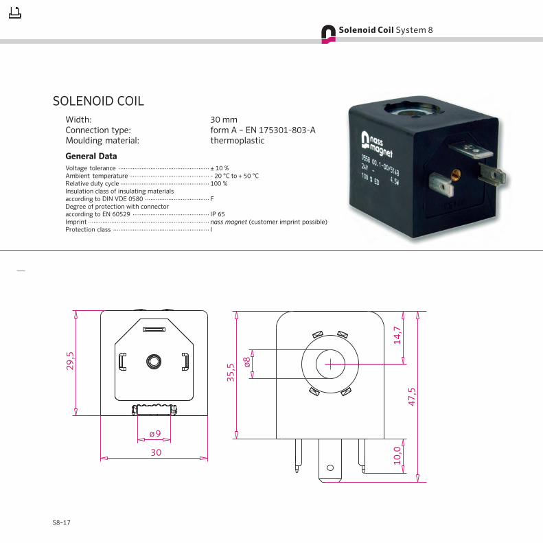
SOLENOID COILWidth: 30 mmConnection type: form A – EN 175301-803-AMoulding material: thermoplastic
General DataVoltage tolerance ··················································· ± 10 %Ambient temperature ············································· - 20 °C to + 50 °CRelative duty cycle ·················································· 100 %Insulation class of insulating materialsaccording to DIN VDE 0580 ···································· FDegree of protection with connectoraccording to EN 60529 ··········································· IP 65Imprint ···································································· nass magnet (customer imprint possible)Protection class ······················································ I

S8–18
Technical Data Standard Versions
Part No. Voltage Frequency [Hz] Rated Power Power Level [K][W] [VA]
108-030-0570 024 V DC – 0,7 1 15
108-030-0559 024 V DC – 2,1 3 35
108-030-0564 012 V DC – 2,6 4 40
108-030-0557 024 V AC 50 05,2 4 70
108-030-0557 024 V AC 60 03,9 4 70
108-030-0560 024 V DC – 2,7 4 40
108-030-0555 048 V DC – 3,4 4 60
108-030-0555 110 V AC 50 04,8 4 60
108-030-0553 220 V AC 50 04,9 4 60
108-030-0553 220 V AC 60 03,7 4 60
108-030-0561 024 V DC – 4,5 5 60
108-030-0554 110 V DC – 6,0 5 75
108-030-0569 110 V DC – 5,3 5 75
108-030-0556 110 V AC 50 07,6 5 70
108-030-0556 120 V AC 60 06,9 5 70
108-030-0554 220 V AC 50 08,0 5 75
108-030-0569 230 V AC 50 07,9 5 75
108-030-0558 012 V DC – 6,2 6 85
108-030-0563 024 V DC – 6,8 6 85
108-030-0563 048 V AC 50 09,9 6 90
108-030-0562 110 V DC – 6,5 6 90
108-030-0565 110 V AC 50 10,5 6 90
108-030-0565 120 V AC 60 09,9 6 90
108-030-0562 220 V AC 50 10,5 6 90
108-030-0568 230 V AC 50 10,5 6 90
108-030-0568 230 V AC 60 07,6 6 90
[K]: steady-state over-temperature according to VDE 0580

S8–19
Circuit Diagram
4
3
SOLENOID COILWidth: 30 mmConnection type: M 12 metal threadMoulding material: thermoset resin
General DataVoltage tolerance ··················································· ± 10 %Ambient temperature ············································· - 20 °C to + 50 °CRelative duty cycle ·················································· 100 %Insulation class of insulating materialsaccording to DIN VDE 0580 ···································· FDegree of protection with connector ······················ IP 65 (IP 67 on request)Imprint ···································································· nass magnet (customer imprint possible)Protection class ······················································ II

S8–20
Technical Data Standard Versions
Part No. Voltage Rated Power [W] Power Level [K] LED Contact 2-pole
108-030-0181 24 V DC 2,7 4 35 yellow x
108-030-0182 24 V DC 4,5 5 60 yellow x
[K]: steady-state over-temperature according to VDE 0580

S8–21
SOLENOID COILWidth: 30 mmConnection type: bayonet (connector DIN 72585)Moulding material: thermoplastic
General DataVoltage tolerance ··················································· ± 10 % (± 30 % on request)Ambient temperature ············································· - 40 °C to + 50 °C
(+ 80 °C on request)Relative duty cycle ·················································· 100 %Degree of protection with connectoraccording to EN 60529 ··········································· IP 6K 9KImprint ···································································· nass magnet (customer imprint possible)Protection class ······················································ III

S8–22
Technical Data Standard Version
Part No. Voltage Rated Power [W] Power Level [K]
108-030-0256 24 V DC 4,5 5 60
[K]: steady-state over-temperature according to VDE 0580

S8–23
The technical data are valid for the indicated standardvoltages. Other voltages are available on request.
Perfect function of these solenoid coils with thepertinent components included in this catalogue isassured with the winding having reached its operatingtemperature (max. ambient temperature and max.voltage tolerance). The steady-state over-temperatureis reached in case of valve bodies of plastic and coilencapsulation made of Thermoplastic. All valves aredesigned in compliance with DIN VDE 0580. Arrange-ment of the valves in modular design is possible, how-ever, it may ensue a higher temperature increased by up
to 20 K and may limit the function. A general lifetime ofthe products cannot be specified, as it is decisivelyinfluenced by ambient conditions, the single applicationand combination with other components. The functioncan only be fulfilled in case of exclusive use of nassmagnet products.
Should there be deviating or additional operatingconditions compared to the abovementioned conditi-ons, special testing is necessary in order to verify theusability of the nass magnet products.
nass magnet will be glad to give you the requiredadvice.
SPECIAL REMARKSNote: The proportions of the solenoid coils displayed in the images on this page do not represent the actual proportions.
Width: 22 mmConnection type: industry formMoulding material: thermosetresin and thermoplastic
Width: 22 mmConnection type: form BMoulding material: thermosetresin and thermoplastic
Width: 22 mmConnection type: flying leadsMoulding material: thermoplastic
Width: 22 mmConnection type:M 12 metal threadMoulding material:thermoset resin
Width: 30 mmConnection type: form AMoulding material: thermosetresin and thermoplastic
Width: 30 mmConnection type:M 12 metal threadMoulding material:thermoset resin
Width: 30 mmConnection type: bayonetMoulding material: thermoplastic
S8–24
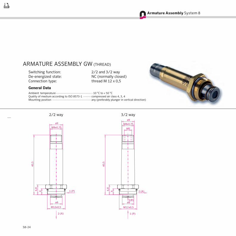
ARMATURE ASSEMBLY GW (THREAD)
Switching function: 2/2 and 3/2 wayDe-energized state: NC (normally closed)Connection type: thread M 12 x 0,5
General DataAmbient temperature ············································· - 10 °C to + 50 °CQuality of medium according to ISO 8573-1 ·········· compressed air class 4, 3, 4Mounting position ·················································· any (preferably plunger in vertical direction)
2/2 way 3/2 way

S8–25
Technical Data Standard Versions
Part No. Function Power Level Nominal Orifice [mm] Pressure [bar] Appropriate for Armature Guideinlet exhaust brass stainless steel
108-010-0082 3/2 way NC 1 0,6 0,8 10 DC x
108-010-0085 3/2 way NC 1 0,8 1,0 08 DC x
108-010-0027 3/2 way NC 2 0,8 1,0 10 DC AC x
108-010-0017 3/2 way NC 3 1,0 1,3 10 DC AC x
108-010-0053 3/2 way NC 3 1,0 1,3 10 DC AC x
108-010-0005 2/2 way NC 3, 4, 5, 6 see below DC AC x
108-010-0014 2/2 way NC 3, 4, 5, 6 see below DC AC x
108-010-0016 3/2 way NC 4 1,3 1,5 10 DC AC x
108-010-0002 3/2 way NC 5 1,5 1,7 10 DC AC x
108-010-0045 3/2 way NC 5 1,5 1,7 10 DC AC x
108-010-0004 3/2 way NC 6 1,7 1,7 10 DC AC x
Power Level 5 Power Level 6
Power Levels for 2/2 Way VersionsAC - 50 Hz AC - 60 Hz DC - 5 % residual ripple max. test pressure: 18 bar · special versions on request
Power Level 3 Power Level 4

S8–26
ARMATURE ASSEMBLY FLSwitching function: 2/2 and 3/2 wayDe-energized state: NC (normally closed),
NO (normally open)Connection type: flange
General DataAmbient temperature ············································· - 10 °C to + 50 °CQuality of medium according to ISO 8573-1 ·········· compressed air class 4, 3, 4Mounting position ·················································· any (preferably plunger in vertical direction)
2/2 way (NC) 3/2 way (NC) 2/2 way (NO) 3/2 way (NO)

S8–27
Power Level 5 Power Level 6
Technical Data Standard Versions
Part No. Function Power Level Nominal Orifice [mm] Pressure [bar] Appropriate for Armature Guideinlet exhaust brass stainless steel
108-010-0081 3/2 way NC 1 0,6 0,8 10 DC x
108-010-0084 3/2 way NC 1 0,8 1,0 08 DC x
108-010-0100 3/2 way NC 1 0,6 0,8 10 DC x
108-010-0026 3/2 way NC 2 0,8 1,0 10 DC AC x
108-010-0007 3/2 way NC 3 1,0 1,3 10 DC AC x
108-010-0010 3/2 way NC 3 1,0 1,3 10 DC AC x
108-010-0006 2/2 way NC 3, 4, 5, 6 see below DC AC x
108-010-0088 2/2 way NC 3, 4, 5, 6 see below DC x
108-010-0009 3/2 way NC 4 1,3 1,5 10 DC AC x
108-010-0049 3/2 way NC 4 1,3 1,5 10 DC AC x
108-010-0172 3/2 way NO 4 1,0 1,3 10 DC x
108-010-0001 3/2 way NC 5 1,5 1,7 10 DC AC x
108-010-0060 3/2 way NC 5 1,5 1,7 10 DC AC x
108-010-0003 3/2 way NC 6 1,7 1,7 10 DC AC x
108-010-0066 3/2 way NC 6 1,7 1,7 10 DC AC x
Power Levels for 2/2 Way VersionsAC - 50 Hz AC - 60 Hz DC - 5 % residual ripple max. test pressure: 18 bar · special versions on request
Power Level 3 Power Level 4

S8–28
VALVE SYSTEM CNOMOHeight: 22 mmSwitching function: 2/2 and 3/2 wayDe-energized state: NC (normally closed), NO (normally open)Valve body: plastics
General DataAmbient temperature ············································· - 10 °C to + 50 °CQuality of medium according to ISO 8573-1 ·········· compressed air class 4, 3, 4Mounting position ·················································· any (preferably plunger in vertical direction)Sealing material ······················································ FPM (other sealing materials on request)
without manualoverride,
NC
monostablemanual override,
NC
bistablemanual override,
NC
without manualoverride,
NO
without manualoverride,
NC
monostablemanual override,
NC
bistablemanual override,
NC
without manualoverride,
NO
Pneumatic Diagram

S8–29
Technical Data Standard Versions
Part No. Power Level Nominal Orifice [mm] Pressure Flow Rate* [l/min] Manual Override Appropriate forinlet exhaust [bar] 1–2 2–3 bistable monostable
108-050-0190 1 0,8 1,0 08 20 30 x DC
108-050-0194 1 0,6 0,7 10 12 22 x DC
108-050-0202 1 0,8 1,0 08 20 30 DC
108-050-0207 1 0,8 1,0 08 20 30 x DC
108-050-0243 2 0,8 1,0 10 20 30 x DC AC
108-050-0109 3 1,0 1,3 10 35 60 x DC AC
108-050-0110 3 1,0 1,3 10 35 60 DC AC
108-050-0126 3 1,0 1,3 10 35 60 x DC AC
108-050-0111 4 1,3 1,5 10 50 75 x DC AC
108-050-0114 4 1,3 1,5 10 50 75 DC AC
108-050-0127 4 1,3 1,5 10 50 75 x DC AC
108-050-0122 5 1,5 1,7 10 65 90 x DC AC
108-050-0124 5 1,5 1,7 10 65 90 DC AC
108-050-0130 5 1,5 1,7 10 65 90 x DC AC
108-050-0116 6 1,3 1,5 16 50 75 x DC AC
108-050-0118 6 1,3 1,5 16 50 75 DC AC
108-050-0125 6 1,7 1,7 10 80 90 DC AC
108-050-0160 6 1,7 1,7 10 80 90 x DC AC
108-050-0137 6 1,3 1,5 16 50 75 x DC AC
* qv flow rate at an inlet pressure of 6 bar (X = 1 bar) and 0 °C; flow rate detection in compliance with ISO 6358Note: Bistable manual override is a combination of the pushing/resetting function and the rotating/latching function.

S8–30
VALVE SYSTEM CNOMOHeight: 22 mmSwitching function: 3/2 way, 2/2 way possible with accessoiresDe-energized state: NC (normally closed), NO (normally open)Valve body: aluminium, coated
General DataAmbient temperature ············································· - 10 °C to + 50 °CQuality of medium according to ISO 8573-1 ·········· compressed air class 4, 3, 4Mounting position ·················································· any (preferably plunger in vertical direction)
without manualoverride,
NC
monostablemanual override,
NC
bistablemanual override,
NC
without manualoverride,
NC
monostablemanual override,
NC
bistablemanual override,
NC
without manualoverride,
NO
Pneumatic Diagram
without manualoverride,
NO

S8–31
Technical Data Standard Versions
Part No. Power Level Nominal Orifice [mm] Pressure Flow Rate* [l/min] Manual Override Appropriate forinlet exhaust [bar] 1–2 2–3 bistable monostable
108-050-0189 1 0,8 1,0 08 20 30 x DC
108-050-0201 1 0,8 1,0 08 20 30 x DC
108-050-0002 3 1,0 1,3 10 35 60 x DC AC
108-050-0242 3 1,0 1,3 10 35 60 DC AC
108-050-0003 4 1,3 1,5 10 50 75 x DC AC
108-050-0023 4 1,3 1,5 10 50 75 x DC AC
108-050-0004 5 1,5 1,7 10 65 90 x DC AC
108-050-0005 5 1,5 1,7 10 65 90 DC AC
108-050-0007 5 1,5 1,7 10 65 90 x DC AC
108-050-0135 5 1,0 1,3 16 35 60 x DC AC
108-050-0006 6 1,7 1,7 10 84 94 DC AC
108-050-0035 6 1,7 1,7 10 84 94 x DC AC
108-050-0037 6 1,3 1,5 16 50 75 x DC AC
* qv flow rate at an inlet pressure of 6 bar (X = 1 bar) and 0 °C; flow rate detection in compliance with ISO 6358Note: Bistable manual override is a combination of the pushing/resetting function and the rotating/latching function.

S8–32
VALVE SYSTEM CNOMOHeight: 30 mmSwitching function: 3/2 way, 2/2 way possible with accessoiresDe-energized state: NC (normally closed)Valve body: plastics
General DataAmbient temperature ············································· - 10 °C to + 50 °CQuality of medium according to ISO 8573-1 ·········· compressed air class 4, 3, 4Mounting position ·················································· any (preferably plunger in vertical direction)Sealing material ······················································ FPM (other sealing materials on request)
without manualoverride, NC
monostablemanual override, NC
bistablemanual override, NC
Pneumatic Diagram
without manualoverride, NC
monostablemanual override, NC
bistablemanual override, NC

S8–33
Technical Data Standard Version
Part No. Power Level Nominal Orifice [mm] Pressure Flow Rate* [l/min] Manual Override Appropriate forinlet exhaust [bar] 1–2 2–3 bistable monostable
108-050-0169 3 1,0 1,3 10 35 60 x DC AC
* qv flow rate at an inlet pressure of 6 bar (X = 1 bar) and 0 °C; flow rate detection in compliance with ISO 6358
Notes:
– Bistable manual override is a combination of the pushing/resetting function and the rotating/latching function.– Switching function 3/2 way NO (normally open) on request
S8–34
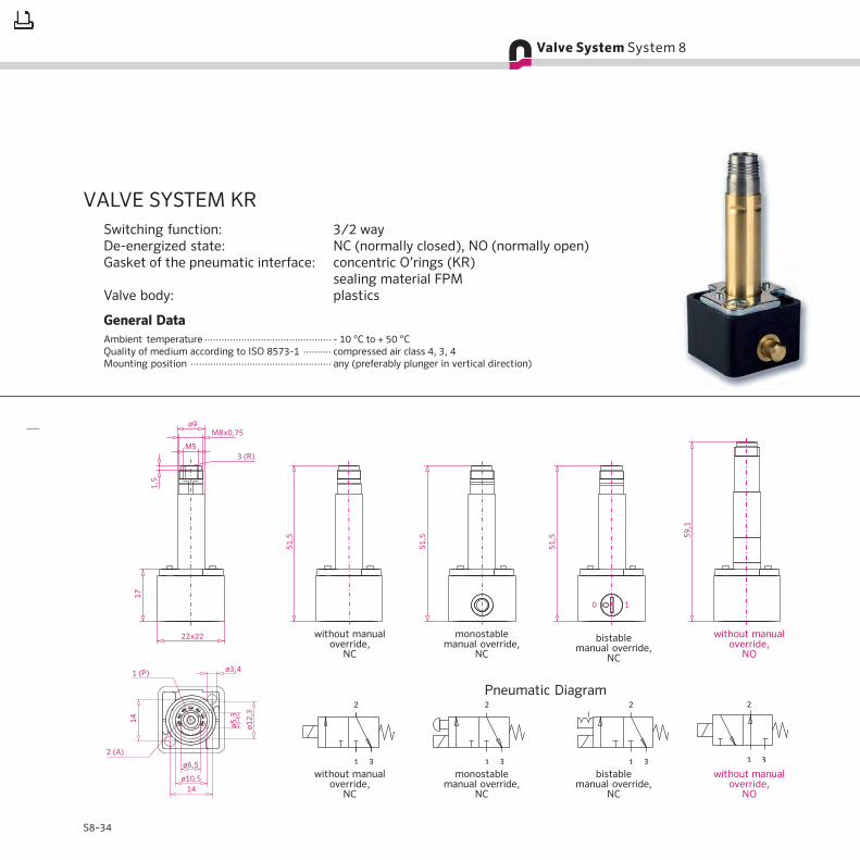
without manualoverride,
NC
monostablemanual override,
NC
bistablemanual override,
NC
without manualoverride,
NO
without manualoverride,
NC
monostablemanual override,
NC
bistablemanual override,
NC
without manualoverride,
NO
Pneumatic Diagram
VALVE SYSTEM KRSwitching function: 3/2 wayDe-energized state: NC (normally closed), NO (normally open)Gasket of the pneumatic interface: concentric O’rings (KR)
sealing material FPMValve body: plastics
General DataAmbient temperature ············································· - 10 °C to + 50 °CQuality of medium according to ISO 8573-1 ·········· compressed air class 4, 3, 4Mounting position ·················································· any (preferably plunger in vertical direction)
S8–35
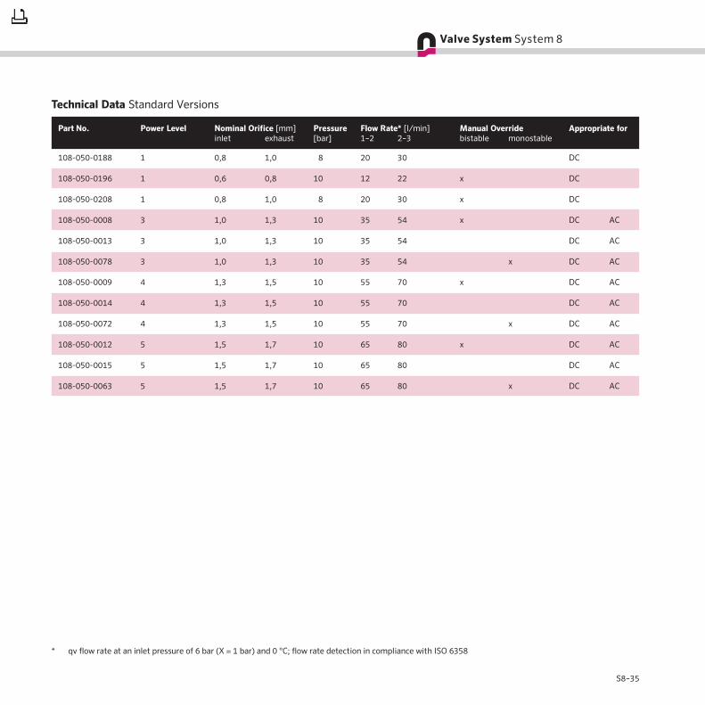
Technical Data Standard Versions
Part No. Power Level Nominal Orifice [mm] Pressure Flow Rate* [l/min] Manual Override Appropriate forinlet exhaust [bar] 1–2 2–3 bistable monostable
108-050-0188 1 0,8 1,0 08 20 30 DC
108-050-0196 1 0,6 0,8 10 12 22 x DC
108-050-0208 1 0,8 1,0 08 20 30 x DC
108-050-0008 3 1,0 1,3 10 35 54 x DC AC
108-050-0013 3 1,0 1,3 10 35 54 DC AC
108-050-0078 3 1,0 1,3 10 35 54 x DC AC
108-050-0009 4 1,3 1,5 10 55 70 x DC AC
108-050-0014 4 1,3 1,5 10 55 70 DC AC
108-050-0072 4 1,3 1,5 10 55 70 x DC AC
108-050-0012 5 1,5 1,7 10 65 80 x DC AC
108-050-0015 5 1,5 1,7 10 65 80 DC AC
108-050-0063 5 1,5 1,7 10 65 80 x DC AC
* qv flow rate at an inlet pressure of 6 bar (X = 1 bar) and 0 °C; flow rate detection in compliance with ISO 6358

S8–36
VALVE SYSTEM GKRSwitching function: 3/2 wayDe-energized state: NC (normally closed), NO (normally open)Gasket of the pneumatic interface: internal exhaust
sealing material FPMValve body: plastics
General DataAmbient temperature ············································· - 10 °C to + 50 °CQuality of medium according to ISO 8573-1 ·········· compressed air class 4, 3, 4Mounting position ·················································· any (preferably plunger in vertical direction)
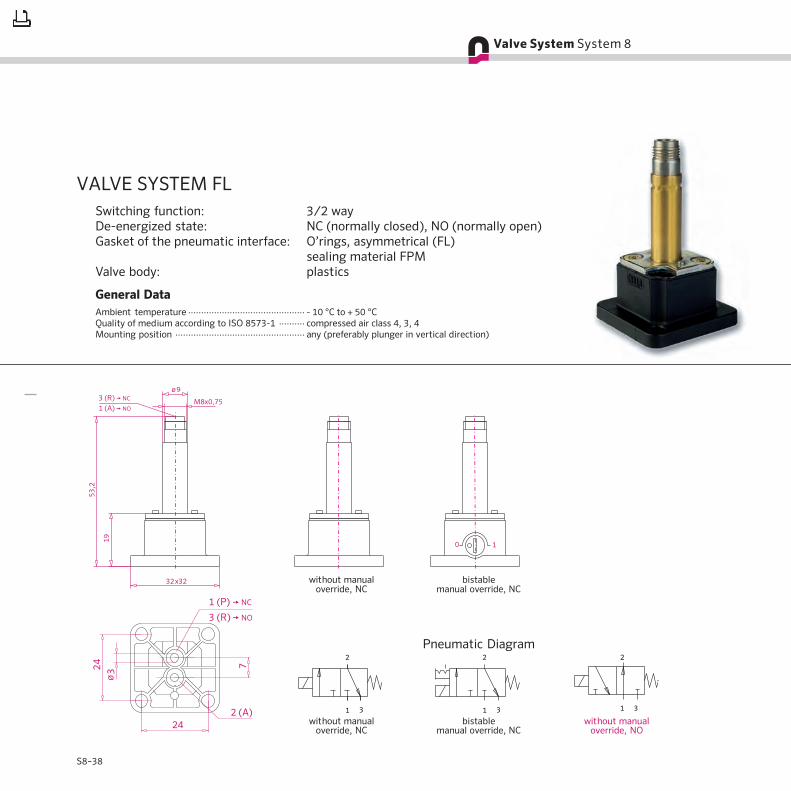
without manualoverride, NC
bistablemanual override, NC
Pneumatic Diagram
without manualoverride, NC
bistablemanual override, NC
without manualoverride, NO
S8–37
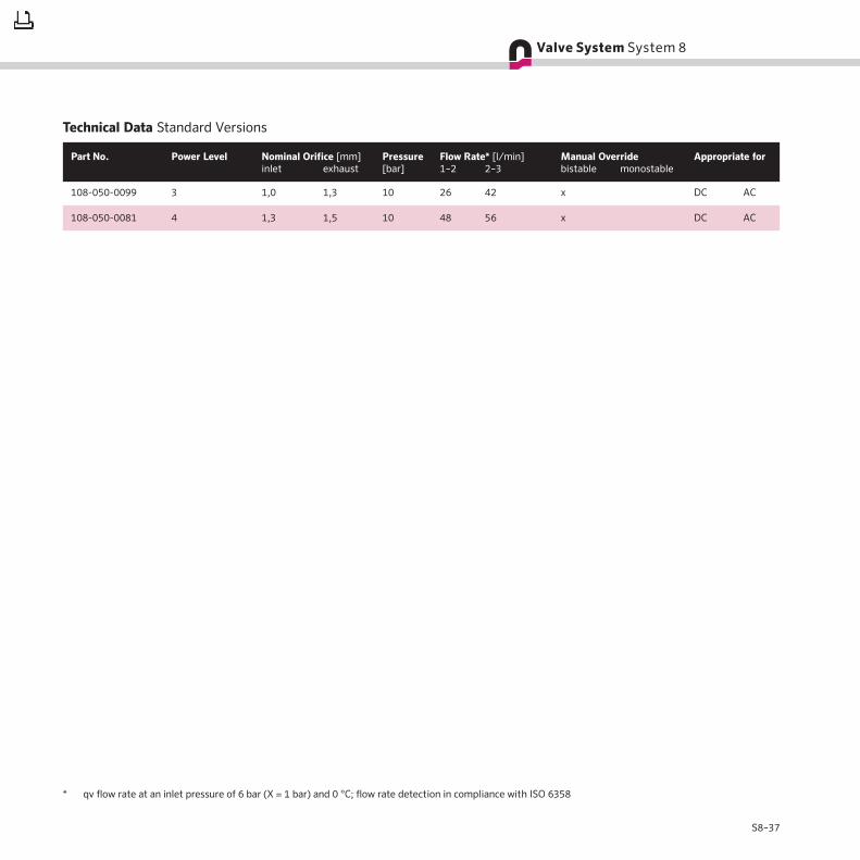
Technical Data Standard Versions
Part No. Power Level Nominal Orifice [mm] Pressure Flow Rate* [l/min] Manual Override Appropriate forinlet exhaust [bar] 1–2 2–3 bistable monostable
108-050-0099 3 1,0 1,3 10 26 42 x DC AC
108-050-0081 4 1,3 1,5 10 48 56 x DC AC
* qv flow rate at an inlet pressure of 6 bar (X = 1 bar) and 0 °C; flow rate detection in compliance with ISO 6358
S8–38
VALVE SYSTEM FLSwitching function: 3/2 wayDe-energized state: NC (normally closed), NO (normally open)Gasket of the pneumatic interface: O’rings, asymmetrical (FL)
sealing material FPMValve body: plastics
General DataAmbient temperature ············································· - 10 °C to + 50 °CQuality of medium according to ISO 8573-1 ·········· compressed air class 4, 3, 4Mounting position ·················································· any (preferably plunger in vertical direction)
without manualoverride, NC
bistablemanual override, NC
without manualoverride, NO
without manualoverride, NC
bistablemanual override, NC
Pneumatic Diagram

S8–39
Technical Data Standard Versions
Part No. Power Level Nominal Orifice [mm] Pressure Flow Rate* [l/min] Manual Override Appropriate forinlet exhaust [bar] 1–2 2–3 bistable without
108-050-0044 3 1,0 1,3 10 25 58 x DC AC
108-050-0045 4 1,3 1,5 10 52 80 x DC AC
108-050-0046 5 1,5 1,7 10 64 88 x DC AC
108-050-0047 5 1,5 1,7 10 64 88 x DC AC
* qv flow rate at an inlet pressure of 6 bar (X = 1 bar) and 0 °C; flow rate detection in compliance with ISO 6358

S8–40
Knurled nut · M 8 x 0,75 mmPart No.: 108-080-0024Explanation: tightening torque max. 1,2 Nm;
use with spring washer #108-080-0022
Spring washerPart No.: 108-080-0022Explanation: use with knurled nut #108-080-0024
Exhaust protector · M 8 x 0,75 mmPart No.: 108-080-0020Explanation: tightening torque max. 0,5 Nm
Mounting platePart No.: 108-702-0011Explanation: for armature
assembly FL only
Valve seat · orifice size 0,8Part No.: 108-034-0005
Knurled nut · M 8 x 0,75 mmPart No.: 108-080-0025Explanation: tightening torque max. 0,5 Nm

S8–41
Cheese-head screw · M 4 x 35 mmPart No.: 900-822-0045Explanation: with slots and cross slots; only for valve system
CNOMO (for one valve system two srews arerequired); tightening torque max. 1,5 Nm
Valve seat · orifice size 1,3Part No.: 108-034-0004
Valve seat · orifice size 1,5Part No.: 108-034-0001
Valve seat · orifice size 1,7Part No.: 108-034-0002
Valve seat · orifice size 2,0Part No.: 108-034-0007
Valve seat · orifice size 1,0Part No.: 108-034-0003

S8–42
Push capPart No.: 108-715-0010Explanation: push and turn actuation, clip-on type, for
monostable manual override; for valve systemCNOMO only
O’ring FPM · 2,5 x 1,5 mmPart No.: 900-841-0065Explanation: only for valve systems KR and GKR
O’ring FPM · 11,5 x 1,5 mmPart No.: 900-841-0077Explanation: only for valve system KR
Cheese-head screw · M 3 x 18 mmPart No.: 900-822-0037Explanation: slotted and with cross recess, tightening torque
max. 0,5 Nm; for valve system KR onlyGasket FPMPart No.: 108-005-0024Explanation: only for valve system GKR
Clamping capPart No.: 108-715-0009Explanation: push and turn actuation, clip-on type, for
bistable manual override; for valve systemCNOMO only

S8–43
O’ring FPM · 3,5 x 1,5 mmPart No.: 900-841-0068Explanation: only for valve system FL
O’ring FPM · 14,0 x 1,0 mmPart No.: 900-841-0082Explanation: to obtain IP 67; for one valve system one O’ring
is required
O’ring FPM · 8,0 x 1,0 mmPart No.: 900-841-0077Explanation: to obtain IP 67; for one valve system two
O’rings are required
Cheese-head screw · M 4 x 12 mmPart No.: 900-822-0041Explanation: tightening torque max. 0,7 Nm ;
for valve system FL only; for one valve systemtwo srews are required
S8–44
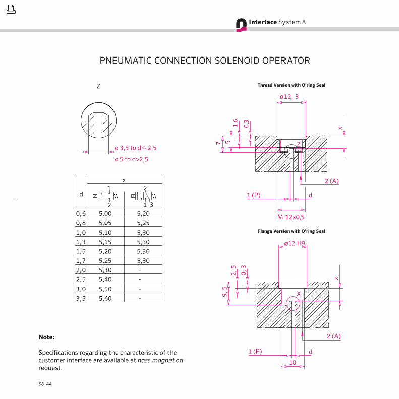
PNEUMATIC CONNECTION SOLENOID OPERATOR
Thread Version with O’ring Seal
Flange Version with O’ring Seal
Note:
Specifications regarding the characteristic of thecustomer interface are available at nass magnet onrequest.


