1 System Architecture Module System Architecture Module System Architecture Module Space Systems Engineering, version 1.0 System Architecture Module Space Systems Engineering, version 1.0 Space Systems Engineering: System Architecture Module Module Purpose: System Architecture Place system architecture development in context with needs analysis, conops, functional analysis and system design. Understand what system architectures are and some techniques for how they are developed. Acknowledge that architecture development is usually an inductive process that benefits from heuristics and the experience of the systems engineer creating the architecture (who is also known as the system architect). Space Systems Engineering: System Architecture Module 2
Transcript
1
System Architecture ModuleSystem Architecture ModuleSystem Architecture Module
Space Systems Engineering, version 1.0
System Architecture Module
Space Systems Engineering, version 1.0
Space Systems Engineering: System Architecture Module
Module Purpose: System Architecture
Place system architecture development in context with needs analysis, conops, functional analysis and system design.
Understand what system architectures are and some ytechniques for how they are developed.
Acknowledge that architecture development is usually an inductive process that benefits from heuristics and the experience of the systems engineer creating the architecture (who is also known as the system architect).
Space Systems Engineering: System Architecture Module 2
2
The Starting Point
“It must be remembered that there is nothing moredifficult to plan, more doubtful of success, nor more dangerous to manage than the creation of a new system.”
- Niccolo Machiavelli, The Prince
Space Systems Engineering: System Architecture Module 3
What Is an Architecture?
It is the fundamental and unifying system structure defined in terms of system elements, interfaces, processes, constraints, and behaviors.
• Source: International Council on Systems Engineering (INCOSE) System Architecture W ki GWorking Group
It is the structure of components, their relationships, and the principles and guidelines governing their design and evolution over time.
• Source: Department of Defense (DOD) Architecture Framework v1.0
Space Systems Engineering: System Architecture Module 4
A system architecture is the link between needs analysis, project scoping and functional analysis and the first descriptions of the system structure.
3
Developing A System Architecture
Creating an architecture is the beginning of the system design process and establishes the link between requirements and design. The typical architecture development sequence is:
1. Establish initial system requirements by needs analysis, project i d h d l f h f i ( )scoping, and the development of the concept of operations (conops).
2. Define the external boundaries, constraints, scope, context, environment and assumptions.
3. Develop candidate system architectures as part of an iterative process using these initial requirements.
Space Systems Engineering: System Architecture Module 5
4. For each architecture, compare the benefits, costs, risks and the requirements that drive their salient features and consider modifying (with stakeholder involvement) their conops, system performance and even their system functions to improve the solution-problem proposition.
Developing Candidate System Architectures is Recursive and Iterative
What needs are we trying to fill? How are current solutions insufficient? Are the needs completely described?
Needs Analysis
Who are the intended users? How will the system be used? How is this use different from heritage
systems?
What capabilities are required? At what level of performance?
ConOps
Functional Requirements
Work With Customer to Potentially Modify Problem Statement Based on Solution
Options
Work With Customer to Potentially Modify
Space Systems Engineering: System Architecture Module 6
Are segment interfaces well defined?
What is the overall approach?What elements make up this approach? Are these elements complete, logical,
and consistent?
System Architectures
to Potentially Modify Problem Statement Based on Solution
Options
4
So How Do We Create Architectures?
There are two primary techniques to create architectures, both benefit from understanding the performance and limitations of heritage systems.
S Synthesis• Modifying or combining existing systems to satisfy stated needs
• Requires logic and good knowledge of existing systems
• What functions do I need to get the job done?
• Can I combine existing systems without too much baggage?
Discovery
Space Systems Engineering: System Architecture Module 7
• Leverage knowledge of existing architectures to ‘discover’ a new one
• Requires knowledge of existing systems and abstraction skills
• Is there an analogous system in another domain?
• What are the good or bad properties of a given architecture?
Four Deductive or Inductive Methods Support Synthesis and Discovery
Science-based, deductive methods:• Normative
• Hard rules are provided (from somewhere), success is defined by following the rules
“If it d ’t l k lik h t d i it t b ”• “If it doesn’t look like what we are doing now it must be wrong.”
• Rational• Solutions derived from objectives
• General systems problem solvers, optimization and formal techniques
• Rule based
Art-based, inductive methods:• Participative
Space Systems Engineering: System Architecture Module 8
• Solution from group process, design by group consensus. Stakeholders involved
• Heuristic• Lessons learned based
• Develop solutions through soft rules that are driven by experience
5
Architecting Focuses on Refining the Problem to Be Solved While Developing Conceptual Solutions
The development of a system architecture, also called ‘architecting’, is a systems engineering responsibility. It is the art and science of purpose determination and concept formulation.
The essence of architecting is structuring, simplification, compromise, and balanceand balance.
This balance is achieved by appropriate compromise between:• System requirements• Function• Form• Simplicity• Robustness• Affordability• Complexity
Space Systems Engineering: System Architecture Module 9
• Environmental imperatives, and• Human factors
Candidate architectures are compared using these factors and a baseline, or agreed to system architecture is chosen.
• A choice is made despite the typically large uncertainties and occasionally ambiguous customer priorities.
Pause and Learn OpportunityPause and Learn Opportunity
Have the students read the article on the Apollo architecture decision to use Lunar Orbit Rendezvous (Apollo_LOR_1971.pdf).
At the board, outline the alternative architectures that were under consideration for the Apollo missions.
Earth orbit rendezvous
Space Systems Engineering: System Architecture Module
Earth-orbit rendezvous
Direct ascent
Lunar-orbit rendezvous
Discuss the pros and cons of each and why LOR became the preferred architecture.
6
Pause and Learn Opportunity part 2Pause and Learn Opportunity, part 2
Extend the discussion to include NASA’s current plans on returning crews to the Moon using a combination of Earth-orbit rendezvous and Lunar-orbit rendezvous.
What are the resulting architecture elements?
What are the pros of this approach?
Space Systems Engineering: System Architecture Module
What are the pros of this approach?
Use the speech by M. Griffin to get a better understanding of the NASA architecture (MG-STA-speech/ESAS-arch_1/22/08.doc).
View the architecture representation with the graphic on the next slide.
NASA Constellation ProgramLunar Sortie Mission Architecture (2006)
Ascent Stage ExpendedLSAM P f LOI100 km
Vehicles are not to scale.
MOONMOON
Ascent Stage ExpendedLSAM P f LOI100 km
Vehicles are not to scale.
MOONMOON
Expended
Earth Departure Stage Expended
LSAM Performs LOI100 km Low Lunar Orbit
Low Earth
Service Module Expended
Expended
Earth Departure Stage Expended
LSAM Performs LOI100 km Low Lunar Orbit
Low Earth
Service Module Expended
Are
s I
Are
s V
Space Systems Engineering: System Architecture Module 12
ED
S,
LSA
M
CE
V
Earth Orbit
p
EARTHEARTH
Direct Entry or Skip Landing
ED
S,
LSA
M
CE
V
Earth Orbit
p
EARTHEARTH
Direct Entry or Skip Landing
7
Architecture vs. Design
A system architecture creates the conceptual structure within which subsequent system design occurs.
Developing a system architecture and developing a system design are systems engineering functions that support systemdesign are systems engineering functions that support system synthesis, but they have different uses.
System architecture is used:• To establish the framework (i.e., constrains the trade space) for subsequent
system design• To support make-buy decisions• To discriminate between alternative solutions• To ‘discover’ the true requirements or the ‘true’ priorities
Space Systems Engineering: System Architecture Module 13
q p
System design is used:• To develop system components that meet functional and performance
requirements and constraints• To build the system• To understand the system-wide ripple effects of configuration changes
Describing a Space System Architecture
No one figure or diagram can capture a system’s architecture -it requires different ‘views’ or perspectives.
Architecture descriptions are what we produce:• Spacecraft renderings and subsystem block diagrams
• Space system communication flow diagrams
• Functional flow diagrams - sometimes captured in functional flow block diagrams (FFBDs; as discussed in Functional Analysis Module)
• Subsystem interface diagrams - frequently captured in N-squared diagrams (as discussed in Interfaces Module)
Space Systems Engineering: System Architecture Module 14
By analogy with a building architecture, these are the blueprints, elevations, floor plans, budgets, wiring plans, etc.
8
The James Webb Space TelescopeCommunications Architecture
L2 Point
Observatory Segment
L2 Lissajous Orbit The launch vehicle injects observatory into an L2
transfer trajectory The observatory operates at L2 point for 5 years with a
goal of 10 years, providing imagery and spectroscopy in the Near and Mid Infrared wavebands.
The Ground Segment receives downloads of science data and sends command uploads during daily 4 hour
JPL
STScI Science & Operations Center (S&OC)
OperationsScript
Subsystem(OSS)
ProjectReference DB
ObservatorySimulators(OTB/STS)
Madrid
ork
(N
ISN
)
L2 Transfer Trajectory
Goldstone Canberra
contacts Ground Segment uploads plans to the Observatory
~once a week and the observatory autonomously executes these plans
NASA ProvidedCommunicationAsset for Early
Orbit Phase
Space Systems Engineering: System Architecture Module 15
JPLDeep Space
Network(DSN)
GSFCFlight
DynamicsFacility (FDF)
FlightOperationsSubsystem
(FOS)
DataManagementSubsystem
(DMS)
WavefrontSensing &
Control Exec(WFSC Exec)
ProposalPlanning
Subsystem(PPS)
Subsystem(PRDS)
NA
SA
In
teg
rate
d S
erv
ices
Net
wo
Launch Segment
Ground Segment
Space Systems Engineering: System Architecture Module 16
9
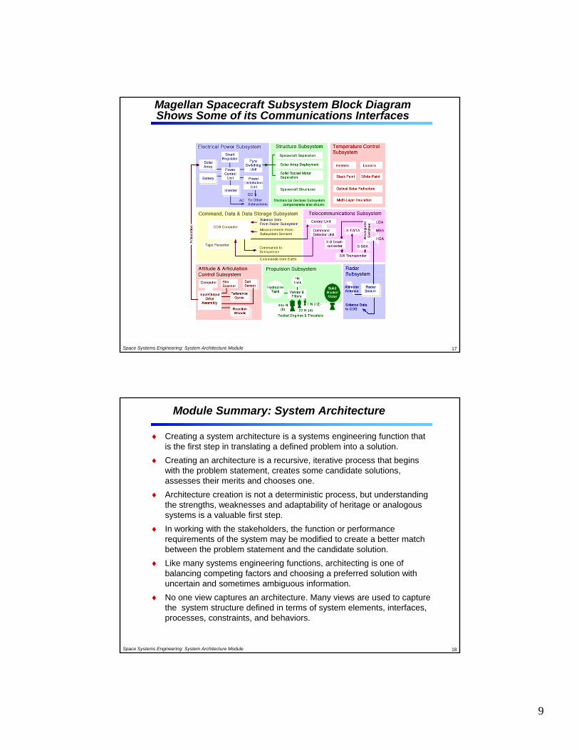
Magellan Spacecraft Subsystem Block Diagram Shows Some of its Communications Interfaces
Space Systems Engineering: System Architecture Module 17
Module Summary: System Architecture
Creating a system architecture is a systems engineering function that is the first step in translating a defined problem into a solution.
Creating an architecture is a recursive, iterative process that begins with the problem statement, creates some candidate solutions, assesses their merits and chooses oneassesses their merits and chooses one.
Architecture creation is not a deterministic process, but understanding the strengths, weaknesses and adaptability of heritage or analogous systems is a valuable first step.
In working with the stakeholders, the function or performance requirements of the system may be modified to create a better match between the problem statement and the candidate solution.
Like many systems engineering functions, architecting is one of
Space Systems Engineering: System Architecture Module 18
balancing competing factors and choosing a preferred solution with uncertain and sometimes ambiguous information.
No one view captures an architecture. Many views are used to capture the system structure defined in terms of system elements, interfaces, processes, constraints, and behaviors.
10
Backup Slidesfor System Architecture Module
Space Systems Engineering: System Architecture Module
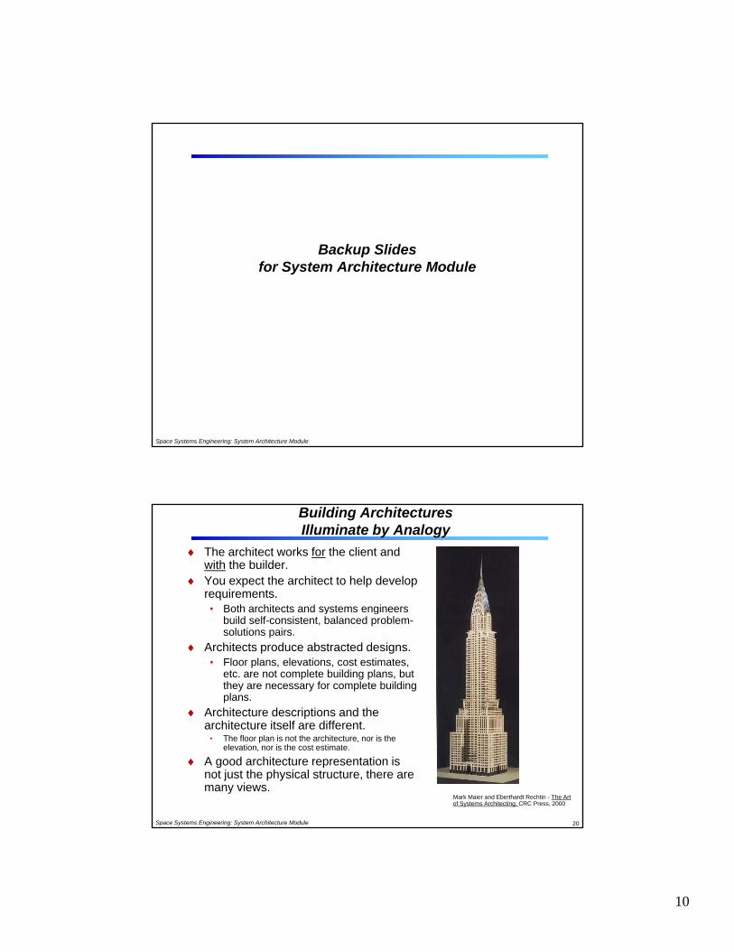
Building Architectures Illuminate by Analogy
The architect works for the client and with the builder.
You expect the architect to help develop requirements.• Both architects and systems engineersBoth architects and systems engineers
- Flight System Mass Breakdown (w. margins)- Flight System Power Breakdown (w. margins)- End-to-End Information System Concept- Data Return Budget and Margins- Design Principles Exceptions- System Margin Summary: mass, power, cost, performance
• Mission Description- Environmental Conditions- Key Drivers- Mission Trades- Orbit and Trajectory (w. margins)- Navigation Concept- Launch Vehicle: Packaging, Mass and Margin; Stowed Configuration; Launch
Strategy• Payload Conceptual Design
- Payload Configuration Diagram (s), Stowed and Deployed- Block Diagram- Heritage (hardware & software)- Mass (w. contingency)- Power (w. contingency)- Size (w. contingency)- Data Rates- Pointing Characteristics
• Flight System Descriptions (bus,lander, etc.)- Configuration Diagram (s), Stowed and Deployed- Subsystem Concepts & Block Diagrams- Heritage (hardware & software)- Mass (w. contingency)- Power (w. contingency)- Size- Downlink/Uplink Rates- Pointing Capability- Thermal Capability- Software Description- Technology Maturity Matrix
• Risk Management Approach- Risk Assessment and Mitigation Strategy and Risk Rating- Risk List
• Costs and Risk Summary- Cost-Risk Estimates by Phase and WBS (w/ reserves)- Schedule Risk (w/ reserves and critical path identified)- Design-to-Cost-Risk Trades
• JPL Institutional Impact Assessment- Workforce Needs- Facilities- DSN Usage- Budget– % Probability of Proceeding to Implementation
12
Product Architecture
Product architecture is the arrangement of the physical elements of a product to carry out its required functions
It is in the Embodiment design phase that the layout and architecture of the product must be established by defining what the basic building blocks of the product should be in terms of what they do and what their i f ill b b h h S i i f hiinterfaces will be between each other. Some organizations refer to this as system-level design
There are two entirely opposite styles of product architecture, modular and integral:
• Modular: components (chunks) implement only one or a few functions and the interactions are well defined
• Integral: implementation of functions uses only one or a few components (chunks) leading to poorly defined interactions
Space Systems Engineering: System Architecture Module 23
p ( ) g p ybetween components (chunks)
In integral product architectures components perform multiple functions
Products designed with high performance as a paramount attribute often have an integral architecture