SSyysstteemm ffoorr SSeeppaarraatt iioonn ooff RReeccyyccllaabblleess UUnniivveerrssii ttyy ooff NNeebbrraasskkaa –– LLiinnccoollnn
Team Members
Boian Berberov [email protected]
Tracy Jamison [email protected]
Jared Stimson [email protected]
Team Mentor
Dr. Hong Jiang [email protected]
System for Separation of Recyclables Team C: Progress Report 2
1
1. Abstract The United States has become a country of mass consumption and this consumption is
pouring millions of tons of waste into landfills every year. This may be more
economical in the short term, but these policies hinge on the extensive depletion of vital
natural resources and will prove devastating to the environment in the future. Landfills
are not a sustainable solution if we continue at our current consumption rates. For
every person in the United States, one ton of trash goes in to a landfill every year. The
most feasible solution to this problem is to recover recyclable material. The widespread
implementation of recycling programs could reduce the disposal of 14.4 million tons
per year of plastics alone [2]; however, there are several factors that prevent an effective
recycling program: participation is usually low, municipal support is can be lacking and
it can be cost prohibitive to process the materials.
State governments have recognized the growing concern over landfills and have
applied pressure to municipal governments in support these programs. For example,
California Assembly Bill 939 required every city and county in California to reduce its
landfill waste stream 25% by 1995 and 50% by the year 2000. Similar mandates are now
in place for many other states [4]. Using material sorting lines in conjunction with
commingled recycling programs can greatly assist municipalities in achieving these
goals.
However, improved participation and efficiency are also necessary if the programs are
to be effective. For this reason, we undertook the development of the System for
Separation of Recyclables (SSR). With this project, we strive to improve the speed and
accuracy of a commingled separation system. Our system also simplifies recycling at
the consumer level and can therefore make it more accepted and widespread.
In support of the project, we have conducted extensive research concerning the current
methods of waste management and we have designed our system to be scalable so that
it will suit the needs of facilities serving small communities or large municipalities.
Through this research we determined that material recovery facilities can have a
dramatic effect on the reliance on landfills. Our system will improve these facilities and
aid in reducing landfill usage and conserving resources.
System for Separation of Recyclables Team C: Progress Report 2
2
2. System Overview This section presents a general overview of the system. First, it details the design
methodology we used. Then it gives a system overview, giving operational and
architectural considerations. Finally, it discusses the innovations this project
introduces.
2.1. Design Methodology When considering the development process for this project, one major constraint for us
has been time. Our team members have very diverse schedules and additional projects
to complete throughout the semester, which limits the total and collective time we can
spend working on the project. Therefore, we needed a development process that would
allow us to work independently and concurrently. We chose a component-based
approach for this project with three phases, as illustrated in Figure 1, to address this
issue.
Figure 1: Design Methodology
2.2. Operational Overview The design of the system is built around a conveyor belt, where a combination of
recyclables and non-recyclables are delivered into the system. Using mechanical
processes, which were not implemented by us, the items arrive separated from one
another and move through the system independently at a nominal interval from each
other. When the items enter the system, they are identified by an RFID reader and the
system begins tracking them as they continue moving through the remaining stages.
When an item arrives at an extraction stage, a rotary extractor will sweep it from the
conveyor belt into a storage container if it is the type of recyclable removed at this stage.
Otherwise, the extractor will remain stationary, allowing the item to simply pass
between its blades. The last stage in the system is designated to collect any recyclables
that may have been missed at previous stages due to error. Any items collected at this
stage are sent back through the system for reprocessing. Finally, items that are not
extracted by the end of the conveyer belt are collected and disposed of as regular waste.
A structural view of the system can be seen in Figure 2. A more detailed description of
System for Separation of Recyclables Team C: Progress Report 2
3
the design and implementation of each component can be found in Section Error!
Reference source not found..
Figure 2: System Diagram
With the last stage and the high accuracy of the RFID reader and optical sensors, this
system will be highly effective. The performance of our system will be more accurate
than the current systems and will have all the benefits of a fully-automated system.
2.3. Innovation In the past, recyclables separation and sorting has been done manually. In recent years,
the use of manual labor has declined for several reasons. Labor costs, decreasing
profits, and safety concerns have all led to the adoption of completely automated
systems that distribute recyclables into segregated containers without the assistance of
human workers. These automated sorting systems may consist of many mechanical
stages or a complicated system of sensors and often are expensive and inefficient [1].
Currently, semi-automated systems are the most common. They consist of a primitive
automated sorting method as the initial stage, combined with manual sorting at the
end.
We have come up with an idea that will make a completely automated system not only
feasible, but also the most economical method for sorting. Our project assumes that
RFID tags have been placed on consumer products at some point in the supply chain, a
likely reality in the near future due to the cost-effectiveness and increasing popularity of
the RFID technology among retailers and manufacturers to enhance product sale and
tracking. These same tags can then be used to improve sorting efficiency by providing
an automated system with a fast and effective method of item identification. Currently,
System for Separation of Recyclables Team C: Progress Report 2
4
materials are sorted by characteristics such as size or composition which is not very
precise and causes lower quality post-recycled products to be manufactured.
3. System Design and Implementation In this section, the development process of our system is described. First, an overall
system design is presented that describes how the individual components interact with
one another. Second, each component is described in detail in its own section. Finally,
testing results of the current implementation are presented.
As described in section 2.1, our team chose a component based approach to developing
our system. After the system operational characteristics were established, the system
was divided into several components to facilitate a fast prototyping cycle. There have
been only minor restructuring in the overall design. The most notable is the recent
combination of the motor controllers and optical sensors into generic stage controllers.
The major components of our system are:
Hardware
• Conveyor Belt
• Rotary Extractor
• Stage Controller
• RFID Reader
• Host Controller
Software
• Software
• Stage Controller Firmware
3.1.1. The Rotary Extractor The rotary extractor is the mechanical component of every extraction stage. This type of
actuator was selected over other designs our group considered because of its fast reset-
time, simplicity, efficiency, and ease of implementation. All of these features are a
product of its one-way motion. Unlike other designs, when the rotary extractor
removes an item from the conveyor belt, it is immediately in a position to remove
another item. There is not return-time like there would be with a push-pull actuator.
This saves both time and energy that would otherwise be wasted in having the actuator
reset. Additionally, the cost of the system is reduced because unidirectional motors can
be used to spin the rotor. These motors are in general more efficient that bidirectional
motors.
System for Separation of Recyclables Team C: Progress Report 2
5
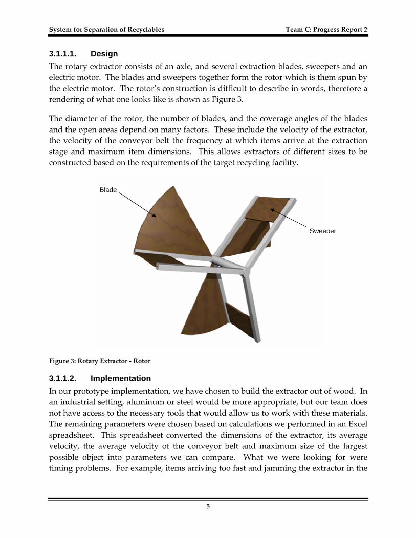
3.1.1.1. Design
The rotary extractor consists of an axle, and several extraction blades, sweepers and an
electric motor. The blades and sweepers together form the rotor which is them spun by
the electric motor. The rotor’s construction is difficult to describe in words, therefore a
rendering of what one looks like is shown as Figure 3.
The diameter of the rotor, the number of blades, and the coverage angles of the blades
and the open areas depend on many factors. These include the velocity of the extractor,
the velocity of the conveyor belt the frequency at which items arrive at the extraction
stage and maximum item dimensions. This allows extractors of different sizes to be
constructed based on the requirements of the target recycling facility.
Figure 3: Rotary Extractor - Rotor
3.1.1.2. Implementation
In our prototype implementation, we have chosen to build the extractor out of wood. In
an industrial setting, aluminum or steel would be more appropriate, but our team does
not have access to the necessary tools that would allow us to work with these materials.
The remaining parameters were chosen based on calculations we performed in an Excel
spreadsheet. This spreadsheet converted the dimensions of the extractor, its average
velocity, the average velocity of the conveyor belt and maximum size of the largest
possible object into parameters we can compare. What we were looking for were
timing problems. For example, items arriving too fast and jamming the extractor in the
Blade
Sweeper
System for Separation of Recyclables Team C: Progress Report 2
6
current inputted configuration. After inputting many different scenarios into the
spreadsheet, we selected the following specifications for the extractors:
Number of blades 3
Diameter 2 ft.
Blade angle 54°
Open space angle 66°
Rotation rate 1 ft. per min.
These specifications were created assuming the conveyor belt moves at 1 foot per
minute and the largest item we will process is a standard, two gallon, milk container.
At this stage in the project’s development, the majority of materials necessary for the
construction of the rotary extractor have been purchased. Currently, time at a
workshop needs to be scheduled so construction can begin on the rotor. The motor has
also been purchased and once the rotor has been completed, an appropriate mount will
be constructed and the extractor will be attached to the conveyor belt. After this is
complete, the rotor will have to be calibrated to work together with the remaining parts
of the system.
3.1.2. Stage controller The stage controller is the electrical component of an extraction stage. Its main purpose
it to control the motion of the rotary extractor and report back when faults occur. Very
recently, the optical sensors in the original system design were redistributed from
having an independent controller to being a part of the motor control circuitry, forming
the combined stage controller. This was possible because of the available
computational power within the PIC18F4550. In addition, the overall design time for
the project was reduced because of the decreased number of different components that
had to be designed. The goals in designing the stage controller were simplicity, low
cost, and ease of configuration.
3.1.2.1. Design
In general, every stage controller has three main parts, a host transceiver, a processing
device, sensor array, and a power section. The host transceiver provides the interface
between the host controller and the processing device. It allows the processing device
to receive instructions and provide status information back to the host controller. For
System for Separation of Recyclables Team C: Progress Report 2
7
easier installation and configuration of the system, it is recommended that the
communication protocol running through the host transceiver supports device
discovery features. The processing device also controls the power section and receives
information from the sensors.
The power section of the controller controls the motor of the rotary extractor. It simply
provides an amplification of the PWM signal that is generated by the processing device.
Finally, the sensor array returns various data about the operation of the stage to the
processing device and from there possibly to the host controller.
3.1.2.2. Implementation
For our prototype implementation, we decided to use a USB interface for the host
transceiver. Automatic discovery and configuration features are already implemented
into the communication protocol, which will reduce the total design time of the device.
In addition, USB also allows multiple devices to connect to our host controller, the
eBox-II.
The power section will be implementing as an optoisolated full-bridge motor driver.
The driver will consist of two components, NEC/CEL’s PS2501-4 photocoupler and
either ST’s L6203 DMOS full-bridge driver or the L298 dual full-bridge driver in parallel
operation to drive more current to the rotary extractor’s motor. The pulse-width
modulated signal for the driver will be provided by the processing device, in our case
the PIC18F4550.
The sensor array will consist of one or more photodetectors that will indicate when an
item is entering the extraction stage. When a photodiode or phototransistor is
illuminated, it conductive properties change, and this change is detectable by an analog
to digital converter like the one in our PIC18F4550. This part of the project is still under
development. The main issues we are concerned with are whether the detector’s
acceptance spectrum is too wide and interference from light sources other than our light
source, a laser diode, might cause a higher failure rate than desired.
The processing device of the controller is the PIC18F4550. This device was selected
because of its integrated USB transceiver and A/D converter, its low cost, good
documentation and recommendation from other students that have used it in the past.
Figure 4 shows how this device integrates with the remaining parts of the controller. As
stated above, the sensor array circuitry is still under development and is not shown.
When it is complete, it will be connected to the A/D ports on the PIC, labeled AN0
through AN7 and colored in red, as seen in Figure 4.
System for Separation of Recyclables Team C: Progress Report 2
8
Figure 4: Stage Controller circuit diagram
3.1.3. Stage controller firmware The stage controller firmware, while an integral part of the controller, is considered a
separate component in our design process and is therefore given a separate section.
System for Separation of Recyclables Team C: Progress Report 2
9
Because this component is specific to our implementation of the system, the design and
implementation subsections have been combined into one.
3.1.3.1. Design and Implementation
At this time in the project’s development, the design stage for this component is not yet
complete. However, the major features that need to be implemented have been
identified and research has been conducted into how these features can be programmed
onto the processing device, the PIC18F4550. The expectation is that this process will not
consume a significant amount of time because of the extensive help Microchip provides
with its products and the availability of many user supported resources.
The features that need to be implemented into the controller firmware are the following:
• Boot loader – for on-site programmability
• USB interface routines – for using the onboard USB transceiver
• Motor control routines – for delivering the correct amount of power to the rotary
extractor’s motor
• A/D conversion routines – for reading sensor data
• Central management routine – contains the main program loop
3.1.4. Conveyor belt The conveyor belt is the central component of the system. It is responsible for
transporting the recyclable items thought the system and it is the base to which all of
the remaining components are attached. For this particular component, there are no
concrete specifications due to the fact that a version of our system may be installed on a
preexisting conveyor belt.
3.1.4.1. Design and Implementation
Originally, our team intended to purchase a conveyor belt to save time during the
component phase, but both of our attempts were unsuccessful. The price of a
commercial conveyor belt restricted our budget and a decision was made to abandon
purchasing the conveyor and attempt to construct one.
Subsequently, a general design was developed and the belt specifications were
finalized. Like the rotary extractors, the conveyor will have a wooden frame. A spring
loaded belt stretching mechanism will keep the belt tight and allow the motor drive it.
It will be 8 feet in length with an 8 inch wide belt and have 6 inch high side panels. This
length allows us to mount all of the rotary extractors and RFID readers. The side panels
are high enough to prevent items from falling off the sides of the belt accidentally.
Additionally, there will be openings along the side for the rotary extractors to move
freely so items can be pushed into the collection bins.
System for Separation of Recyclables Team C: Progress Report 2
10
3.1.5. Computational hardware (Host controller) The computational hardware for this system is an eBox-II, a compact embedded system
provided by the Microsoft Corporation. The operating system running on eBox will be
Microsoft’s Windows Mobile 5.0. This platform was selected because of its low cost and
availability.
For the system in general, the processing power of this hardware is important. The
more powerful the hardware, the more extraction stages can be simultaneously
connected to and controlled by it. In out implementation the eBox processor is
sufficient for our three extractors. In terms of connectivity, the necessary interfaces,
USB and serial, for communicating with the stage controllers are also provided.
Currently, we have not begun integrating the eBox in to our implementation. There are
issues with the RFID reading software components that need to be resolved before we
can migrate the controlling software.
3.1.6. Software Software is an important part of this system. Its interaction with the hardware is very
important to proper system operation. This section describes the interaction with the
hardware, the design of the software, and what is currently implemented.
3.1.6.1. Interaction with Hardware
The software is used as a tool to control the system as a whole, handle errors, and move
the extractors. For control of the system, it receives information from multiple optical
sensors and RFID readers. It also signals for – and controls – the movement of the
rotary extractors. The software constantly polls the optical sensors and the final RFID
reader to see if there is any change – that is, if there is an item breaking the optical
sensor beam, or if the final RFID reader is picking up the signal of an item. The flow of
control and hardware/software interaction can be seen in Figure 5.
As an item moves through the system on the conveyer belt, it encounters the first
optical sensor and RFID reader. When the item breaks the beam of the optical sensor,
the software detects the change in state after it polls the sensor the next time. At this
time, the software signals the RFID reader so the tag on the item can be read. If no tag
is read or the tag does not include information for a valid recyclable, the item is marked
as trash. If a valid tag has been read, the software determines what type of recyclable
the item is and at which stage it should be extracted.
Once the software has determined the type of recyclable, it decides what the next action
is. For a Type A recyclable (extracted at the first stage), the software signals the first
extractor to move after a short delay. This allows the item to enter the collection area of
System for Separation of Recyclables Team C: Progress Report 2
11
the first stage. If the extraction fails, the item is placed on the queue to be extracted at
the last stage, which allows it to be recirculated through the system. If the recyclable is
a Type B recyclable, it is added to the queue to be extracted at the second stage.
Items still on the conveyer belt after the first stage are either Type B, trash, or Type A
that is still on the conveyer due to an error. When the software polls the sensors and
the second optical sensor is triggered, the software checks to see if the item – which is at
the front of the queue – is a Type B recyclable. If it is, the software creates a delay, and
then signals for the second extractor to move. It then removes the item from the queue.
If the item is anything except a Type B recyclable, it is removed from the queue – being
either trash or a valid recyclable that will be caught at the last stage.
The final stage removes any type of valid recyclable. The second RFID reader is polled
by the software, just as the optical sensors are. If either Type A or Type B recyclables
are sensed, the extractor is moved after a delay to extract the item for recirculation
through the system again. Otherwise, the items move to the end of the conveyer belt
and fall off the end into a trash bin.
System for Separation of Recyclables Team C: Progress Report 2
12
Figure 5: Hardware/Software Interaction
System for Separation of Recyclables Team C: Progress Report 2
13
3.1.6.2. Design
Design of the software for controlling the system as a whole as well as the software that
handles error control was done at the start of the project. UML diagrams such as class
and sequence diagrams were used to aid the design process. This helped get the ideas
solidified in a standardized way so that everyone could understand the design. The
design for the system is such that the system could be easily expanded at a later time to
hold more stages. Once the design was complete, the software was developed.
Just as the conveyer belt is central to the physical system, a queue is central to the
software that controls our system. Item objects are placed on the queue, when
necessary. The rest of the logic comes from the flow of the system, seen in Figure 5:
Hardware/Software Interaction.
3.1.6.3. Implementation
At this point, the software that is used to control the system is mostly complete. Since
the optical sensors are not finished, the software prompts the user to enter a Y or N for
each optical sensor to indicate if it has been triggered. This sets off the same chain of
events as if the optical sensor was integrated.
The error control software is partially implemented. For most cases, we will allow the
problem item to pass through to the end. This error catch has been completed. We do
not, however, have the software to back the extractor up if it is jammed. This will
happen once everything else has been put together.
3.1.6.4. Tools
For testing the system software, we developed extra methods within the software to
view the status of the system at various points. This is also useful for providing
demonstrations of the system and simulation before all the hardware is complete.
We also created another test program to verify the queue class was working properly.
This program followed the test suite we wrote, and made sure all the functionality was
verified.
4. Testing Testing has been conducted on several system components. The following sections
describe in detail how the testing done on the system.
4.1.1. Hardware A prototype of the stage controller with limited functionality has been tested. The
prototype was capable of communicating with a host PC through its USB interface.
From the PC, the velocity of the motor could be controlled by sending a 10 bit number
System for Separation of Recyclables Team C: Progress Report 2
14
that determined the duty cycle of the pulse width modulator. The pulse width
modulator then controlled a simple MOSFET amplifier that delivered power to the
electric motor.
From experimenting with the prototype, we determined that a minimum starting power
was required to get the motor to spin. In our case, a value of 350 had to be sent by the
PC. As we increased the input value from the PC, the motor responded almost linearly.
We had difficulty achieving maximum velocity, which was likely due to the design of
the MOSFET amplifier.
4.1.2. Software Software testing has been done in two segments. This follows design and development,
which was done in two parts. To keep track of items, the software keeps a queue,
which holds the necessary information about each item on the conveyer belt. Since this
part is so important to the rest of the software, it was implemented – and therefore
tested – first. The different functions of the queue were methodically tested.
The software as a whole was tested once the whole system was implemented. While
the software was being written, the separate parts were tested ad hoc. A test suite was
written for fuller coverage of testing once everything was written. This is important
because it creates written documentation of what has and has not been tested. System
testing is categorized three ways: adding items, removing items, and miscellaneous
other tasks the software must perform. At this time, all tests have been run and have
passed for the functionality that is implemented.
5. Summary Currently, all component design phases have been completed except for the optical
sensor circuitry. The software has been developed and currently runs on the Windows
XP operating system. We expect to migrate to the eBox once the stage controllers have
been constructed. All of the parts of the stage controllers are currently on order as of
the writing of this report. The expectation is to have them constructed before the end of
the week following the report submission. The optical sensors will have to be attached
at a later time, once the circuit design has been finalized. The majority of the rotary
extractor and conveyor belt parts have also been purchased. Scheduling workshop time
has prevented us from building these components thus far.
The design of the system is well thought out and thoroughly developed. The goal of
our prototype implementation was to demonstrate that such a system was feasible and
would perform reasonably well for a first prototype. There are many ways that our
general design can be expanded and a better system for larger-scale operations. The
System for Separation of Recyclables Team C: Progress Report 2
15
most obvious way is to add additional stages for finer-grain separation. Additional
stages may necessitate a different communication interface between the computational
hardware and the stage controllers. The rotary extractors can be scaled for faster
system operation, and the number of conveyor belts controlled by a single
computational hardware may be increased.
Additionally, the information gathered from our system need not be limited to simply
the identification of type of recyclable for sorting. There is a significant amount of
statistical information that can be obtained from a simple RFID tag affixed to the side of
a consumer product. These tags are being used throughout the supply chain for
shipment and inventory management, and we plan to extend their usefulness by using
them to identify and extract recyclable materials from common household waste. The
information that we could retrieve during the disposal phase would provide useful
product information to marketers and allow them to track general consumption
statistics. This allows for the creation of more effective marketing campaigns and gives
consumers what they want. We anticipate that as RFID tags become more cost effective,
they will be used more extensively in the supply chain and our system will utilize them
to identify and sort many different materials at material recovery facilities.
6. References [1] Design of a Materials Recovery Facility (MRF) For Processing the Recyclable
Materials of New York City’s Municipal Solid Waste: Prof. Nickolas J. Themelis,
Columbia University.
[2] Municipal Solid Waste, http://www.epa.gov, accessed on 11 February 2006.
[3] Wikipedia, Materials Recovery Facility,
http://en.wikipedia.org/wiki/Materials_Recovery_Facility_(MRF), 13 February 2006
[4] California Assembly Bill 939, AMENDED IN ASSEMBLY JUNE 2, 2003
http://www.mhac.org/Legislation/Priority.MHAC.Bills.7.18.03/ab939.pdf4


![[ Resampled Range of Witty Titles]](https://static.documents.pub/doc/80x56/56815e2d550346895dcc8716/-resampled-range-of-witty-titles.jpg)


