93
R System Generator for DSP Getting Started Guide Release 10.1 March, 2008
| Date post: | 02-Jun-2018 |
| Category: |
Documents |
| Upload: | matthew-thomas |
| View: | 314 times |
| Download: | 13 times |

8112019 System Generator for DSP Getting Started
httpslidepdfcomreaderfullsystem-generator-for-dsp-getting-started 193
R
SystemGenerator forDSP
Getting Started Guide
Release 101 March 2008
8112019 System Generator for DSP Getting Started
httpslidepdfcomreaderfullsystem-generator-for-dsp-getting-started 293
System Generator for DSP wwwxilinxcom Release 101 March 2008
Xilinx is disclosing this Document and Intellectual Property (hereinafter ldquothe Designrdquo) to you for use in the development of designs to operateon or interface with Xilinx FPGAs Except as stated herein none of the Design may be copied reproduced distributed republisheddownloaded displayed posted or transmitted in any form or by any means including but not limited to electronic mechanicalphotocopying recording or otherwise without the prior written consent of Xilinx Any unauthorized use of the Design may violate copyrightlaws trademark laws the laws of privacy and publicity and communications regulations and statutes
Xilinx does not assume any liability arising out of the application or use of the Design nor does Xilinx convey any license under its patentscopyrights or any rights of others You are responsible for obtaining any rights you may require for your use or implementation of theDesign Xilinx reserves the right to make changes at any time to the Design as deemed desirable in the sole discretion of Xilinx Xilinxassumes no obligation to correct any errors contained herein or to advise you of any correction if such be made Xilinx will not assume anyliability for the accuracy or correctness of any engineering or technical support or assistance provided to you in connection with the Design
THE DESIGN IS PROVIDED ldquoAS ISrdquo WITH ALL FAULTS AND THE ENTIRE RISK AS TO ITS FUNCTION AND IMPLEMENTATION ISWITH YOU YOU ACKNOWLEDGE AND AGREE THAT YOU HAVE NOT RELIED ON ANY ORAL OR WRITTEN INFORMATION ORADVICE WHETHER GIVEN BY XILINX OR ITS AGENTS OR EMPLOYEES XILINX MAKES NO OTHER WARRANTIES WHETHEREXPRESS IMPLIED OR STATUTORY REGARDING THE DESIGN INCLUDING ANY WARRANTIES OF MERCHANTABILITYFITNESS FOR A PARTICULAR PURPOSE TITLE AND NONINFRINGEMENT OF THIRD-PARTY RIGHTS
IN NO EVENT WILL XILINX BE LIABLE FOR ANY CONSEQUENTIAL INDIRECT EXEMPLARY SPECIAL OR INCIDENTAL
DAMAGES INCLUDING ANY LOST DATA AND LOST PROFITS ARISING FROM OR RELATING TO YOUR USE OF THE DESIGNEVEN IF YOU HAVE BEEN ADVISED OF THE POSSIBILITY OF SUCH DAMAGES THE TOTAL CUMULATIVE LIABILITY OF XILINX INCONNECTION WITH YOUR USE OF THE DESIGN WHETHER IN CONTRACT OR TORT OR OTHERWISE WILL IN NO EVENTEXCEED THE AMOUNT OF FEES PAID BY YOU TO XILINX HEREUNDER FOR USE OF THE DESIGN YOU ACKNOWLEDGE THATTHE FEES IF ANY REFLECT THE ALLOCATION OF RISK SET FORTH IN THIS AGREEMENT AND THAT XILINX WOULD NOT MAKEAVAILABLE THE DESIGN TO YOU WITHOUT THESE LIMITATIONS OF LIABILITY
The Design is not designed or intended for use in the development of on-line control equipment in hazardous environments requiring fail-safe controls such as in the operation of nuclear facilities aircraft navigation or communications systems air traffic control life support orweapons systems (ldquoHigh-Risk Applicationsrdquo) Xilinx specifically disclaims any express or implied warranties of fitness for such High-RiskApplications You represent that use of the Design in such High-Risk Applications is fully at your risk
copy 2002-2008 Xilinx Inc All rights reserved XILINX the Xilinx logo and other designated brands included herein are trademarks of XilinxInc PowerPC is a trademark of IBM Inc All other trademarks are the property of their respective owners
R
8112019 System Generator for DSP Getting Started
httpslidepdfcomreaderfullsystem-generator-for-dsp-getting-started 393
Release 101 March 2008 wwwxilinxcom System Generator for DSP
Preface About This Guide
Guide Contents 7
System Generator PDF Doc Set 7
Additional Resources 8
Conventions 8
Typographical 8Online Document 9
Chapter 1 Introduction
The Xilinx DSP Block Set 12
FIR Filter Generation 13
Support for MATLAB 14
System Resource Estimation 15
Hardware Co-Simulation 16
System Integration Platform 17
Chapter 2 Installation
Downloading 19Hardware Co-Simulation Support 19
Installing 19Software Prerequisites 19Using the ISE Design Suite Installer 20Hardware Co-Simulation Installation 20Compiling Xilinx HDL Libraries 21Configuring the System Generator Cache 21Displaying and Changing Versions of System Generator 21
Chapter 3 Release InformationRelease Notes 101 23
System Generator Enhancements 23Xilinx DSP Blockset Enhancements 24Tool Flow and Integration 24
Release Notes 9201 25System Generator Enhancements 25Xilinx DSP Blockset Enhancements 29Tool Flow and Integration 29Known Issues 29
Release Notes 9200 30
System Generator Enhancements 30Xilinx DSP Blockset Enhancements 33Tool Flow and Integration 34Known Issues 34
Release Notes 9101 35System Generator Enhancements 35Xilinx DSP Blockset Enhancements 35Tool Flow and Integration 36Migrating Designs Created in Previous Versions of Software 36
Table of Contents
8112019 System Generator for DSP Getting Started
httpslidepdfcomreaderfullsystem-generator-for-dsp-getting-started 493
Release 101 March 2008 wwwxilinxcom System Generator for DSP
Upgrading a Xilinx System Generator Model 37Upgrading v2x and Prior Models 37Upgrading v3x v6x and v7x Models 37Examples 38
Chapter 4 Getting Started
Introduction 39
Lesson 1 - Design Creation Basics 40The System Generator Design Flow 40The Xilinx DSP Blockset 41Defining the FPGA Boundary 42Adding the System Generator Token 43Creating the DSP Design 44Generating the HDL Code 45Model-Based Design using System Generator 46Creating Input Vectors using MATLAB 47Lesson 1 Summary 48Lab Exercise Using Simulink 48
Lab Exercise Getting Started with System Generator 48Lesson 2 - Fixed Point and Bit Operations 49
Fixed-Point Numeric Precision 49System Generator Fixed-Point Quantization 50Overflow and Round Modes 51Bit-Level Operations 52The Reinterpret Block 53The Convert Block 54The Concat Block 55Slice Block 56The BitBasher Block 57Lesson 2 Summary 58Lab Exercise Signal Routing 58
Lesson 3 - System Control 59Controlling a DSP System 59The MCode Block 60The Xilinx ldquoxl_staterdquo Data Type 61State Machine Example 62The Expression Block 63Reset and Enable Ports 64Bursty Data 65Lesson 3 Summary 66Lab Exercise System Control 66
Lesson 4 - Multi-Rate Systems 67Creating Multi-Rate Systems 67
Up and Down Sampling Blocks 68Rate Changing Functional Blocks 69Viewing Rate Changes in Simulink 70Debugging Tools 71Sample Period ldquoRulesrdquo 72Lab Exercise Multi-Rate Systems 73
Lesson 5 - Using Memories 74Block vs Distributed RAM 74Initializing RAMs and ROMs 75
8112019 System Generator for DSP Getting Started
httpslidepdfcomreaderfullsystem-generator-for-dsp-getting-started 593
Release 101 March 2008 wwwxilinxcom System Generator for DSP
System Generator RAM Blocks 76System Generator ROM Blocks 77The Delay Block 78The FIFO Block 79Lab Exercise Using Memories 80
Lesson 6 - Designing Filters 81
Introduction 81The Virtex DSP48 Math Slice 82FIR Compiler Block 83Creating Coefficients with FDATool 84Using FDA Tool Coefficients 85Lab Exercise Designing Filters 86
Additional Examples and Tutorials 87Black Box Examples 87ChipScope Examples 87DSP Examples 88M-Code Examples 89Processor Examples 89Shared Memory Examples 90Timing Analysis Examples 91Miscellaneous Examples 91System Generator Demos 92
Index 93
8112019 System Generator for DSP Getting Started
httpslidepdfcomreaderfullsystem-generator-for-dsp-getting-started 693
System Generator for DSP wwwxilinxcom Release 101 March 2008
8112019 System Generator for DSP Getting Started
httpslidepdfcomreaderfullsystem-generator-for-dsp-getting-started 793
System Generator for DSP wwwxilinxcom 7Release 101 March 2008
R
Preface
About This Guide
This Getting Started Guide introduces you to System Generator for DSP then providesinstallation and configuration instructions release information and six mini-trainingmodules that highlight the main features of the product Each module starts with a lessonof 8-10 slides that explain important concepts followed by a lab exercise that take about 30minutes to complete Because this introductory training is part of the tool you canprogress through the material at your own pace and on your own time schedule
Guide Contents
This Getting Started Guide contains the following topics
bull Introduction
bull Installation
bull Release Information
bull Getting Started
a Design Creation Basics
b Fixed Point and Bit Operations
c System Control
d Multi-Rate Systems
e Using Memories
f Designing Filters
g Additional Examples and Tutorials
System Generator PDF Doc Set
This Getting Started Guide can be found in the System Generator Help system and is alsopart of the System Generator Doc Set that is provided in PDF format The content of thedoc set is as follows
bull
System Generator for DSP Getting Started Guidebull System Generator for DSP User Guide
bull System Generator for DSP Reference Guide
Note Hyperlinks across these PDF documents work only when the PDF files reside in the samefolder After clicking a Hyperlink in the Adobe Reader you can return to the previous page by pressingthe Alt key and the left arrow key (larr) at the same time
8112019 System Generator for DSP Getting Started
httpslidepdfcomreaderfullsystem-generator-for-dsp-getting-started 893
8 wwwxilinxcom System Generator for DSPRelease 101 March 2008
Preface About This Guide R
Additional Resources
To find additional documentation see the Xilinx website at
httpwwwxilinxcomliterature
To search the Answer Database of silicon software and IP questions and answers or to
create a technical support WebCase see the Xilinx website athttpwwwxilinxcomsupport
Conventions
This document uses the following conventions An example illustrates each convention
Typographical
The following typographical conventions are used in this document
Convention Meaning or Use Example
Courier font Messages prompts andprogram files that the systemdisplays
speed grade - 100
Courier bold Literal commands that youenter in a syntactical statement
ngdbuild design_name
Helvetica bold Commands that you select froma menu
File rarrOpen
Keyboard shortcuts Ctrl+C
Italic font Variables in a syntax statementfor which you must supplyvalues
ngdbuild design_name
References to other manuals See the Development SystemReference Guide for moreinformation
Emphasis in text If a wire is drawn so that itoverlaps the pin of a symbolthe two nets are not connected
Square brackets [ ] An optional entry or parameterHowever in bus specificationssuch as bus[70] they arerequired
ngdbuild [option_name]design_name
Braces A list of items from which youmust choose one or more
lowpwr =on|off
Vertical bar | Separates items in a list ofchoices
lowpwr =on|off
8112019 System Generator for DSP Getting Started
httpslidepdfcomreaderfullsystem-generator-for-dsp-getting-started 993
System Generator for DSP wwwxilinxcom 9Release 101 March 2008
ConventionsR
Online Document
The following conventions are used in this document
Vertical ellipsis
Repetitive material that has been omitted
IOB 1 Name = QOUTrsquoIOB 2 Name = CLKINrsquo
Horizontal ellipsis Repetitive material that has been omitted
allow block block_name loc1loc2 locn
Convention Meaning or Use Example
Convention Meaning or Use Example
Blue text Cross-reference link to alocation in the currentdocument
See the topic ldquoAdditionalResourcesrdquo for details
Refer to ldquoTitle Formatsrdquo in
Chapter 1 for detailsRed text Cross-reference link to a
location in another documentSee Figure 2-5 in the Virtex-IIPlatform FPGA User Guide
Blue underlined text Hyperlink to a website (URL) Go to httpwwwxilinxcom for the latest speed files
8112019 System Generator for DSP Getting Started
httpslidepdfcomreaderfullsystem-generator-for-dsp-getting-started 1093
10 wwwxilinxcom System Generator for DSPRelease 101 March 2008
Preface About This Guide R
8112019 System Generator for DSP Getting Started
httpslidepdfcomreaderfullsystem-generator-for-dsp-getting-started 1193
System Generator for DSP wwwxilinxcom 11Release 101 March 2008
R
Chapter 1
Introduction
System Generator is a DSP design tool from Xilinx that enables the use of The Mathworksmodel-based design environment Simulink for FPGA design Previous experience withXilinx FPGAs or RTL design methodologies are not required when using SystemGenerator Designs are captured in the DSP friendly Simulink modeling environmentusing a Xilinx specific blockset All of the downstream FPGA implementation stepsincluding synthesis and place and route are automatically performed to generate an FPGAprogramming file
8112019 System Generator for DSP Getting Started
httpslidepdfcomreaderfullsystem-generator-for-dsp-getting-started 1293
12 wwwxilinxcom System Generator for DSPRelease 101 March 2008
Chapter 1 Introduction R
The Xilinx DSP Block Set
Over 90 DSP building blocks are provided in the Xilinx DSP blockset for Simulink These blocks include the common DSP building blocks such as adders multipliers and registersAlso included are a set of complex DSP building blocks such as forward error correction blocks FFTs filters and memories These blocks leverage the Xilinx IP core generators to
deliver optimized results for the selected device
8112019 System Generator for DSP Getting Started
httpslidepdfcomreaderfullsystem-generator-for-dsp-getting-started 1393
System Generator for DSP wwwxilinxcom 13Release 101 March 2008
FIR Filter GenerationR
FIR Filter Generation
System Generator includes a FIR Compiler block that targets the dedicated DSP48hardware resources in the Virtex4 and Virtex5 devices to create highly optimizedimplementations that can run in excess of 500 Mhz Configuration options allowgeneration of direct polyphase decimation polyphase interpolation and oversampled
implementations Standard MATLAB functions such as fir2 or The Mathworks FDAtoolcan be used to create coefficients for the Xilinx FIR Compiler
8112019 System Generator for DSP Getting Started
httpslidepdfcomreaderfullsystem-generator-for-dsp-getting-started 1493
14 wwwxilinxcom System Generator for DSPRelease 101 March 2008
Chapter 1 Introduction R
Support for MATLAB
Algorithmic MATLAB models can be incorporated into System Generator throughAccelDSP AccelDSP includes powerful algorithmic synthesis that takes floating-pointMATLAB as input and generates a fully scheduled fixed-point model for use with SystemGenerator Features include floating- to fixed-point conversion Automatic IP insertion
design exploration and algorithmic scheduling Also included in System Generator is anMCode block that allows the use of non-algorithmic MATLAB for the modeling andimplementation of simple control operations
8112019 System Generator for DSP Getting Started
httpslidepdfcomreaderfullsystem-generator-for-dsp-getting-started 1593
System Generator for DSP wwwxilinxcom 15Release 101 March 2008
System Resource EstimationR
System Resource Estimation
System Generator provides a Resource Estimator block that quickly estimates the area of adesign prior to place and route This can be a valuable aid in the hardware softwarepartitioning process by helping system designers take full advantage of the FPGAresources which include up to 640 multiplyaccumulate (or DSP) blocks in the Virtex5
devices
8112019 System Generator for DSP Getting Started
httpslidepdfcomreaderfullsystem-generator-for-dsp-getting-started 1693
16 wwwxilinxcom System Generator for DSPRelease 101 March 2008
Chapter 1 Introduction R
Hardware Co-Simulation
System Generator provides accelerated simulation through hardware co-simulationSystem Generator will automatically create a hardware simulation token for a designcaptured in the Xilinx DSP blockset that will run on one of over 20 supported hardwareplatforms This hardware will co-simulate with the rest of the Simulink system to provide
up to a 1000x simulation performance increase
8112019 System Generator for DSP Getting Started
httpslidepdfcomreaderfullsystem-generator-for-dsp-getting-started 1793
System Generator for DSP wwwxilinxcom 17Release 101 March 2008
System Integration PlatformR
System Integration Platform
System Generator provides a system integration platform for the design of DSP FPGAsthat allows the RTL Simulink MATLAB and CC++ components of a DSP system to cometogether in a single simulation and implementation environment System Generatorsupports a black box block that allows RTL to be imported into Simulink and co-simulated
with either ModelSim or Xilinx ISE Simulator System Generator also supports theinclusion of a MicroBlaze embedded processor running CC++ programs
8112019 System Generator for DSP Getting Started
httpslidepdfcomreaderfullsystem-generator-for-dsp-getting-started 1893
18 wwwxilinxcom System Generator for DSPRelease 101 March 2008
Chapter 1 Introduction R
8112019 System Generator for DSP Getting Started
httpslidepdfcomreaderfullsystem-generator-for-dsp-getting-started 1993
System Generator for DSP wwwxilinxcom 19Release 101 March 2008
R
Chapter 2
Installation
Downloading
System Generator is only available via download from the Xilinx web page You maypurchase register and download the System Generator software from the site at
httpwwwxilinxcomiseoptional_prodsystem_generatorhtm
Note In special circumstances System Generator can be delivered on a CD Please contact your
Xilinx distributor if your circumstances prohibit you from downloading the software via the web
Hardware Co-Simulation Support
If you have an FPGA development board you may be able to take advantage of SystemGeneratorrsquos ability to use FPGA hardware co-simulation with Simulink simulations TheSystem Generator software includes support for the XtremeDSP Development Kit theMicroBlaze Multimedia Demonstration boards the MVI hardware platform the ML402Virtex-4 platform the ML506 Virtex-5 platform and the Spartan-3A DSP 1800 starterplatform and 3400 development platform Additional System Generator board supportpackages provide support for additional hardware co-simulation platforms SystemGenerator board support packages can be downloaded from the following URL
httpwwwxilinxcomtechnologydspthirdparty_devboardshtm
Installing
Software Prerequisites
You must have the following software installed before running System Generator
bull One of the following versions of MATLAB from The MathWorks Inc
bull MATLAB v74Simulink v66 (R2007a)
bull MATLAB v75Simulink v70 (R2007b)
Note MATLAB must be installed in a directory with no spaces (eg CMATLABR2007a)
bull Xilinx ISE Foundation version 101
Some features in System Generator require the following software to be installed
bull A logic synthesis tool System Generator is fully compatible with Xilinx XST (includedin the ISE Foundation bundle) and Synplify Pro v862 or v89 from Synplicity Inc
bull A hardware description language (HDL) simulator is required only for co-simulatingHDL modules within Simulink using System Generator System Generator HDL co-simulation interfaces are compatible with the Xilinx ISE Simulator ModelSim Xilinx
8112019 System Generator for DSP Getting Started
httpslidepdfcomreaderfullsystem-generator-for-dsp-getting-started 2093
20 wwwxilinxcom System Generator for DSPRelease 101 March 2008
Chapter 2 Installation R
Edition MXE (an option with ISE Foundation) and ModelSim PE or SE version v63cfrom Model Technology Inc
Note The Microsoft Windows environment variable $XILINX must be set and point to your ISEsoftware installation directory
ISE software service packs may be downloaded from the Xilinx Download Center
httpwwwxilinxcomxlnxxil_sw_updates_homejsp
Using the ISE Design Suite Installer
Before invoking the ISE Design Suite Installer it is a good idea to make sure that allinstances of MATLAB are closed When all instances of MATLAB are closed launch theinstaller and follow the directions on the screen
Choose MATLAB Version for System Generator
As the last step of the System Generator installation click the check box of the MATLABinstallation you wish to associate with this verison of System Generator then click Apply
If you donrsquot see a valid version of MATLAB listed for example a version installed on anetwork device click the Add Version button browse to the MATLAB root directory of theunlisted version then click Add If you wish to associate this version of MATLAB withSystem Generator click the check box of the newly listed MATLAB installation then clickApply
If you have no version of MATLAB available click Choose Later to continue with theinstallation At a later time after you have installed MATLAB you can associate thatversion of MATLAB with System Generator by executing the Windows menu item Start gtAll Programs gt Xilinx ISE Design Suite 101 gt DSP Tools gt Select MATLAB version forXilinx System Generator
Hardware Co-Simulation Installation
This topic provides links to hardware and software installation procedures for hardwareco-simulation If you do not plan to use hardware co-simulation you may skip this topic
Ethernet-Based Hardware Co-Simulation
Installing an ML402 Board for Ethernet Hardware Co-Simulation
Installing an ML506 Board for Ethernet Hardware Co-Simulation
Installing a Spartan-3A DSP 1800A Starter Platform for Ethernet Hardware Co-Simulation
Installing a Spartan-3A DSP 3400A Development Platform for Ethernet Hardware Co-Simulation
JTAG-Based Hardware Co-Simulation Installing an ML402 Board for JTAG Hardware Co-Simulation
Third-Party Hardware Co-Simulation
As part of the Xilinx XtremeDSPtrade Initiative Xilinx works with distributors and manyOEMs to provide a variety of DSP prototyping and development platforms Please refer tothe following Xilinx web site page for more information on available platformshttpwwwxilinxcomtechnologydspthirdparty_devboardshtm
8112019 System Generator for DSP Getting Started
httpslidepdfcomreaderfullsystem-generator-for-dsp-getting-started 2193
System Generator for DSP wwwxilinxcom 21Release 101 March 2008
InstallingR
Compiling Xilinx HDL Libraries
If you intend to simulate System Generator designs using ModelSim you must compileyour IP (cores) libraries This topic describes the procedure
ModelSim (PE or EESE)
The Xilinx tool that compiles libraries for use in ModelSim PE or EESE is namedcompxlib The following command can for example be used to compile all the VHDL andVerilog libraries with ModelSim SE
compxlib ndashs mti_se ndashf all ndashl all
Complete instructions for running compxlib can be found in the ISE Software Manualtitled ldquoSynthesis and Simulation Design Guiderdquo
MXE Libraries
If you plan to use ModelSim XE (Xilinx Edition) download the MXE precompiled librariesfrom the Xilinx web site Unzip these MXE libraries into the directory in which you haveMXE installed eg cModeltech_XE This is the location where MXE expects to find
your Xilinx compiled libraries so it is not necessary to change your modelsimini file Thisfile should point to the correct installed location
Configuring the System Generator Cache
Both the System Generator simulator and the design generator incorporate a disk cache tospeed up the iterative design process The cache does this by tagging and storing filesrelated to simulation and generation then recalling those files during subsequentsimulation and generation rather than rerunning the time consuming tools used to createthose files
Setting the Size
By default the cache will use up to 500 MB of disk space to store files To specify theamount of disk space the cache should use set the SYSGEN_CACHE_SIZE environmentvariable to the size of the cache in megabytes Set this number to a higher value whenworking on several large designs
Setting the Number of Entries
The cache entry database stores a fixed number of entries The default is 20000 entries Toset size of the cache entry database set the SYSGEN_CACHE_ENTRIES environmentvariable to the desired number of entries Setting this number too small will adverselyaffect cache performance Set this number to a higher value when working on several largedesigns
Displaying and Changing Versions of System Generator
It is possible to have several versions of System Generator installed The MATLABcommand xlVersion displays which versions are installed and makes it possible toswitch from one to another xlVersion is useful when upgrading a model to run in thelatest version of System Generator
Entering xlVersion in the MATLAB console displays the versions of System Generatorthat are installed and entering xlVersion ltversiongt switches to the specified
8112019 System Generator for DSP Getting Started
httpslidepdfcomreaderfullsystem-generator-for-dsp-getting-started 2293
22 wwwxilinxcom System Generator for DSPRelease 101 March 2008
Chapter 2 Installation R
version For example if the versions that are installed are 9201 and 101 and the currentlyselected version is 101 then entering xlVersion displays
Available System Generator installationsVersion 9201 in CXilinx9201DSP_ToolssysgenVersion 101 in CXilinx101DSP_Toolssysgen
Current version of System Generator is 101
Entering xlVersion 9201 switches the System Generator version to 9201
Occasionally it is necessary to restart MATLAB to make it possible to switch In this casethe response to entering xlVersion 101 looks like the following
Please restart MATLAB and run xlVersion 101 again to switch
When the switch succeeds xlVersion prints the following
Your System Generator has been switched Please restart MATLAB
If you install System Generator 101 after you install 9201 you need to install 101 again inorder to make xlVersion work
Once you switch System Generator version you need to switch to the right version of ISEin order to make System Generator work correctly
8112019 System Generator for DSP Getting Started
httpslidepdfcomreaderfullsystem-generator-for-dsp-getting-started 2393
System Generator for DSP wwwxilinxcom 23Release 101 March 2008
R
Chapter 3
Release Information
Release Notes 101
System Generator Enhancements
System Generator Project Navigator Integration
System Generator designs can now be more easily incorporated into a larger design insideof Project Navigator by using a new source type in Project Navigator The SystemGenerator design can also be launched from Project Navigator
DCM Support
System Generator now provides the option to automatically include a DCM in a designAlthough the optional DCM is abstracted away from the designer the generated designwill leverage DCMs available in the silicon
An alternative option exposes the clock ports at the top level for manual connection to aDCM
Dual Asynchronous-Clock Support for PLB46
This capability gives the designer additional flexibility by allowing the DSP andembedded processing portions of a design to run at different clock rates
Run Time Speed Improvements
bull Up to 2x faster first time initialization of a simulation
bull gt10x faster initialization when loading the Xilinx Blockset in the Simulink LibraryBrowser
M-Based HW Co-Simulation
System Generator models compiled for HW Co-Simulation can now be embeddedconfigured and utilized in a MATLAB M-code script allowing for calls into hardware to bemade from MATLAB
8112019 System Generator for DSP Getting Started
httpslidepdfcomreaderfullsystem-generator-for-dsp-getting-started 2493
24 wwwxilinxcom System Generator for DSPRelease 101 March 2008
Chapter 3 Release Information R
Xilinx DSP Blockset Enhancements
FFT 50
Update to existing block which now includes cyclic prefix insertion
FIR Compiler 32Update which now include support for Virtex II and Spartan 3A
Reset Generator
New block that produces synchronized downsampled reset signals which eliminates theneed to manually create these signals
CIC Compiler 11
New block now available in System Generator
Tool Flow and IntegrationSystem Generator 101 is compatible with the following tools
Tool Version
The Mathworks MATLABreg and Simulink 2007a and 2007b
Mentor Graphics ModelSimreg SE 63c
Synplicity Synplify Proreg 8804 (Requires a floating license forHardware Co-Simulation)
Xilinxreg AccelDSP 101
Xilinxreg ChipScope Pro 101
Xilinxreg EDK 101
Xilinxreg ISE 101
Xilinxreg ISE IP Update 101 IP Update 1
Xilinxreg ISE Simulator 101
8112019 System Generator for DSP Getting Started
httpslidepdfcomreaderfullsystem-generator-for-dsp-getting-started 2593
System Generator for DSP wwwxilinxcom 25Release 101 March 2008
Release Notes 9201R
Release Notes 9201
System Generator Enhancements
EDK 92 SP1 PLBv46 amp MB 70 Support
This release of System Generator supports Embedded Design Kit (EDK) Release 92SP1and the MicroBlaze PLB v46 bus interface As shown in the figure below when you exporta System Generator design as a MicroBlaze processor core (pcore) using the EDK Processor block you can choose to connect the pcore to the MicroBlaze v46 bus or the previouslysupported FSL (Fast Simplex Link) The PLB v46 is now the default choice
When you select the PLB v46 option the target MicroBlaze processor must have a PLBv46 bus properly connected to the DPLB interface and a proc_sys_reset module connectedto the system reset pin Also both the pcore PLB memory map and the PLB bus should runat the same operating frequency These requirements will be in place if you use the XPSBase System Builder to build the MicroBlaze processor
Specifying a PLB v46 Base Address When you select the PLB v46 (Processor Local Bus)option the bus address space will be automatically adjusted and minimized If you knowwhere you want the bus address space to start you enter the address and click LockOtherwise the base address will be automatically determined for you This Base Addressoption is not used with the FSL Bus Type
Note Software simulation is disabled in this release You can simulate the processorsubsystem within System Generator and Simulink by connecting a supported hardwareplatform to your host computer and using Hardware Co-Simulation See the topic UsingHardware Co-Simulation for details
Pcore Export Enhancements
The EDK Export Tool has been enhanced to provide the following new features
Asynchronous Software Drivers for FSLs
FSL-based pcores connect to the MicroBlaze processor using FIFOs It is possible for usersin XPS to connect one clock to the processor and another to the System Generator pcore In
the past if you did this there was a chance that data would be lostIn the release you can set your software drivers to work in polling mode Polling driverswill keep retrying (for a programmable number of times) to read or write data Pollingdrivers are less efficient but they are tolerant to clock differences between the Processorand Pcore
To configure the software driver in Xilinx Platform Studio (XPS) you select the menuSoftware gt Software Platform Settings to get the following dialog box shown below You
8112019 System Generator for DSP Getting Started
httpslidepdfcomreaderfullsystem-generator-for-dsp-getting-started 2693
26 wwwxilinxcom System Generator for DSPRelease 101 March 2008
Chapter 3 Release Information R
click on Drivers and if Sysgen-based FSL pcores are available driver parameters will bepresent as shown below Select SG_POLLING to be true to enable polling drivers
Export as Pcore Under Development
This feature works for both FSL- and PLB-based pcore export When a pcore is marked asPcore under development XPS will not cache the HDL produced for this pcore This isuseful when you are developing pcores in System Generator and testing them out in XPSYou can just enable this checkbox make changes in System Generator and compile in XPS
XPS always compiles the generated pcore so you donrsquot have to empty the XPS cache whichmay contain caches of other peripherals thus slowing down the compile of the final bitstream
Enable Custom Bus Interfaces
This feature works for both FSL- and PLB-based pcore export and allows you to createcustom bus interfaces that will be understood in XPS
8112019 System Generator for DSP Getting Started
httpslidepdfcomreaderfullsystem-generator-for-dsp-getting-started 2793
System Generator for DSP wwwxilinxcom 27Release 101 March 2008
Release Notes 9201R
Improved EDK Processor Bitstream Support
When you perform bitstream compilation on a System Generator design with an EDKProcessor block the imported EDK project and the shared memories sitting between theSystem Generator design and MicroBlaze processor are netlisted along with the SystemGenerator design and included in the resulting bitstream
System Generator also attempts to compile any active software programs inside theimported EDK project If the compilation of active software programs succeeds SystemGenerator invokes the data2bram utility to include the compiled software programs intothe resulting bitstream
Note No error or warning message is issued when System Generator encounters failures duringsoftware program compilation or when System Generator updates the resulting bitstream with thecompiled software programs
Once the bitstream is generated you can modify the software programs in the importedEDK project and use the following command to compile the software programs andupdate the System Generator bitstream without re-running Place amp Route
xlProcBlockCallbacks(updatebitstream [] xmp_file bit_file bmm_file)
wherebull xmp_file is the pathname to the imported EDK project file
bull bit_file is the pathname to the Sysgen bitstream file
bull bmm_file is the pathname of the back-annotated BMM file produced by Sysgenduring bitstream compilation
If the imported EDK project contains a BMM file named imported_edk_projectbmmSystem Generator creates a back-annotated BMM file namedimported_edk_project_bdbmm You should provide the later back-annotated BMMfile to the above command in order to update the bitstream properly
Spartan-3A DSP 1800A Starter Platform Support
System Generator now supports the Spartan-3A DSP 1800A Starter Platform for EthernetPoint-to-Point Hardware Co-Simulation
Spartan-3A DSP 3400A Development Platform Support
System Generator now supports the Spartan-3A DSP 3400A Development Platform forHardware Co-Simulation Both the Point-to-point Ethernet configuration as well as theNetwork-Based Ethernet configuration are supported
Simulation Speed Improvements
Simulation speed for designs created with the Xilinx DSP Blockset has been improvedsubstantially in System Generator 9201 This speedup is relative to the number of blocksin the design with large designs over 2000 blocks showing a 5x to 10x run timeimprovement The following Simulink solver settings must be used to achieve the
8112019 System Generator for DSP Getting Started
httpslidepdfcomreaderfullsystem-generator-for-dsp-getting-started 2893
28 wwwxilinxcom System Generator for DSPRelease 101 March 2008
Chapter 3 Release Information R
maximum simulation performance improvement These solver settings can beautomatically configured by typing the ldquoxlConfigureSolverrdquo command at the MATLABconsole
RTL Improvements
In this release if two or more Simulink Sub-systems are exactly the same including inputdata types and mask parameters only a single VHDL entity or Verilog module will begenerated then instantiated multiple times in the HDL code generated by SystemGenerator This optimization improves HDL logic synthesis runtime while reducing theamount of memory consumed by XST
New JTAG Cable Sharing Option
A new option called Shared cable for concurrent access has been added to the propertiesdialog box for the JTAG Co-Simulation block This option allows the JTAG cable to beshared with EDK XMD during a JTAG co-simulation
When the option is checked the JTAG co-simulation engine only acquires a lock on thecable access and then immediately releases the lock when the access completes Otherwisethe JTAG co-simulation engine holds the lock throughout the simulation Due to thesignificant overhead on locking and unlocking the cable this cable sharing option isdisabled by default and only enabled when you check the box
8112019 System Generator for DSP Getting Started
httpslidepdfcomreaderfullsystem-generator-for-dsp-getting-started 2993
System Generator for DSP wwwxilinxcom 29Release 101 March 2008
Release Notes 9201R
Xilinx DSP Blockset Enhancements
Convolutional Encoder v61
bull Support has been added for Spartan-3A DSP
Reed-Solomon Decoder v61bull Support has been added for Spartan-3A DSP
bull The Field Polynomial entry in the GUI is now entered as a decimal number ratherthan a binary string
Reed-Solomon Encoder v61
bull Support has been added for Spartan-3A DSP
bull The Field Polynomial entry in the GUI is now entered as a decimal number ratherthan a binary string
Viterbi Decoder v61
bull Support has been added for Spartan-3A DSP
Tool Flow and Integration
System Generator 9201 is compatible with the following tools
Known Issues
Known issues with this release can be found on the Xilinx web site at the followingaddress
httpwwwxilinxcomxlnxxil_ans_displayjspgetPagePath=29595
Tool Version
The Mathworks MATLABreg and Simulink 2006b and 2007a
Mentor Graphics ModelSimreg SE 61f
Synplicity Synplify Proreg 8804 (Requires a floating license for
Hardware Co-Simulation)Xilinxreg AccelDSP 9201
Xilinxreg ChipScope Pro 9203i
Xilinxreg EDK EDK 92 SP1
Xilinxreg ISE 9203i
Xilinxreg ISE IP Update 92i IP Update 1
Xilinxreg ISE Simulator 9203i
8112019 System Generator for DSP Getting Started
httpslidepdfcomreaderfullsystem-generator-for-dsp-getting-started 3093
30 wwwxilinxcom System Generator for DSPRelease 101 March 2008
Chapter 3 Release Information R
Release Notes 9200
System Generator Enhancements
Single DSP Tools Installer using Xilinx Unified Installer
All Xilinx DSP Tools now use a Unified Installer for software installation andconfiguration
System Generator MATLAB Selector
As part of the unified installation process this configuration feature allows the useradditional flexibility to specify which version of MATLABSimulink should be associatedwith a particular version of System Generator This is helpful for users who have morethan one version of MATLABSimulink or System Generator on their machine
Selectable Block Frequency for Hardware Co-Simulation
If you are using a Xilinx ML402 or ML506 platform at netlist time System Generator allowsyou to choose a clock frequency for the target design that is equal to or less than the systemclock frequency The following table outlines the frequencies that are available
Platform InterfaceSystem Clock
Frequency
Available
Frequencies
Xilinx ML402 JTAGPoint-to-point EthernetNetwork-based Ethernet
100 MHz 100 MHz
667 MHz
50 MHz
333 MHz
Xilinx ML506 Point-to-point EthernetNetwork-based Ethernet
200 MHz 100 MHz
667 MHz
50 MHz
333 MHz
8112019 System Generator for DSP Getting Started
httpslidepdfcomreaderfullsystem-generator-for-dsp-getting-started 3193
System Generator for DSP wwwxilinxcom 31Release 101 March 2008
Release Notes 9200R
As shown below you set the target clock frequency at compilation time by clicking theSettings button on the System Generator block dialog box then select the frequency in thepulldown menu
Clock Enable Fanout Reduction
A new mapping algorithm has been implemented that uses register duplication andplacement based on recursive partitioning of loads on high fanout nets This meansimproved FMAX on System Generator designs with large CE fanout
Although this feature is enabled in System Generator by default the fanout reductionoccurs downstream during the ISE mapping operation and the following MAP optionsmust be turned on
bull Perform Timing-Driven Packing and Placement on
bull Map Effort Level High
bull Register Duplication on
If you are using the ISE Project Navigator flow these MAP options are also on by defaultHowever if you are using the default System Generator netlisting flow you must turnthese MAP options on by modifying the bitstream opt file or by providing your own optfile
Shared Memory Stitching
Starting with this release if two Shared Memory blocks with the same name existanywhere in the design hierarchy then during netlisting the two blocks will be stitchedinto a single Shared Memory block If a single Shared Memory block exists then the inputand output ports of the block are pushed to the top-level of the design
If more than two Shared Memory blocks with the same name exist then an error occurs
This new stitching feature also applies to To FIFO and From FIFO block pairs with thesame name and To Register and From Register block pairs with the same name
2 Select
1 Click
8112019 System Generator for DSP Getting Started
httpslidepdfcomreaderfullsystem-generator-for-dsp-getting-started 3293
32 wwwxilinxcom System Generator for DSPRelease 101 March 2008
Chapter 3 Release Information R
For backward compatibility you can set the MATLAB global variablexlSgSharedMemoryStitch to ldquooffrdquo to bring System Generator back to the netlisting behavior before the 92 release For example from the MATLAB command line enter thefollowing
global xlSgSharedMemoryStitchxlSgSharedMemoryStitch = off
System Generator Requires a Simulink Variable-step Solver
Simulink divides simulation solvers into two types fixed-step and variable-step Bothtypes of solvers compute the next simulation time as the sum of the current simulationtime and a quantity known as the step size With a fixed-step solver the step size remainsconstant throughout the simulation By contrast with a variable-step solver the step sizecan vary from step to step depending on the models dynamics In particular a variable-step solver reduces the step size when a models states are changing rapidly to maintainaccuracy and increases the step size when the systems states are changing slowly in orderto avoid taking unnecessary steps
System Generator requires that you use a Variable-step solver for every Simulinksimulation The use of a Fixed-step solver is not supported and will be explicitlydisallowed in a future release Using a Fixed-step solver might result in an inaccurateSystem Generator simulation
As shown below to choose a Variable-step solver select Simulation gt ConfigurationParameters from the Simulink pulldown menu then choose Variable-step from theSolver options
1 Select
2 Select
3 Observe
8112019 System Generator for DSP Getting Started
httpslidepdfcomreaderfullsystem-generator-for-dsp-getting-started 3393
System Generator for DSP wwwxilinxcom 33Release 101 March 2008
Release Notes 9200R
Xilinx DSP Blockset Enhancements
DDS Compiler v2_0
bull Supports LogiCORE DDS Compiler 20
bull Support has been added for Spartan-3A DSP
bull New controls have been introduced to expose the rfd and rdy output ports Thisfeature has also been added to DDS Compiler v11
bull channel input port has been renamed channelsel to avoid confusion with the channeloutput port
bull Core initialization times have been significantly reduced both for DDS Compiler v11and DDS Compiler v20
FIR Compiler v3_1
bull Supports LogiCORE FIR Compiler 31
bull Faster simulation speeds when using re-loadable coefficients
bull Support for Rounding in the FIR Compiler core through the following newparameters on the Advanced Pane of the Parameters dialog box
diams Rounding mode List box with the following options
- Full_Precision
- Truncated_LSBS
- Non_Symmetric_Rounding_Down
- Non_Symmetric_Rounding_Up
- Convergent_Rounding_To_Even
- Convergent_Rounding_To_Odd
- Symmetric_Rounding_To_Zero
- Symmetric_Rounding_To_One- Symmetric_Rounding_To_Infinity
diams Output Width An editbox specifying the output width which is activated only ifthe Rounding mode is set to a value other than Full_Precision
diams Allow Rounding Approximation Check box that specifies if approximations can be allowed to save resources when using symmetric rounding
Help System Improvements
The System Generator Help System has gone through a major upgrade that includes a newHTML browser a new comprehensive index and full text search capability
8112019 System Generator for DSP Getting Started
httpslidepdfcomreaderfullsystem-generator-for-dsp-getting-started 3493
34 wwwxilinxcom System Generator for DSPRelease 101 March 2008
Chapter 3 Release Information R
Tool Flow and Integration
System Generator 9200 is compatible with the following tools
Known Issues
Known issues with this release can be found on the Xilinx web site at the followingaddress
httpwwwxilinxcomxlnxxil_ans_displayjspgetPagePath=29110
Tool Version
The Mathworks MATLABreg and Simulink 2006b and 2007a
Mentor Graphics ModelSimreg SE 61f
Synplicity Synplify Proreg 8804 (Requires a floating license forHardware Co-Simulation)
Xilinxreg AccelDSP 9200
Xilinxreg ChipScope Pro 9202i
Xilinxreg EDK EDK support is not available in this releaseof System Generator and is expected toreturn in the next service pack
Xilinxreg ISE 9202i
Xilinxreg ISE IP Update 92i IP Update 1Xilinxreg ISE Simulator 9202i
8112019 System Generator for DSP Getting Started
httpslidepdfcomreaderfullsystem-generator-for-dsp-getting-started 3593
System Generator for DSP wwwxilinxcom 35Release 101 March 2008
Release Notes 9101R
Release Notes 9101
System Generator Enhancements
New Technologies Supported
Spartantrade-3A DSP The new Spartantrade-3A DSP series targets cost-sensitive high-performance signal processing applications
Xilinx DSP Blockset Enhancements
FIR Compiler v3_0
bull Supports LogiCORE FIR Compiler 30
bull Support has been added for Spartan-3A DSP
bull Supports interpolated filter implementations
bull Maximum number of channels increased to 64
bull Maximum integer rate change increased to 64
bull Now exploits symmetry when interpolating by an even rate with an odd number ofcoefficients reducing resource utilization
DDS Compiler v1_1
bull Supports LogiCORE DDS Compiler 11
bull Support added for Virtextrade-5 and Spartantrade-3A
DSP48 Macro
bull Support added for DSP48A slice
bull The DSP48 Macro block provides a device independent abstraction for the DSP48DSP48E and DSP48A slices
DSP48A
bull Supports DSP48A slice
bull The DSP48A slice is unique to the Spartantrade-3A DSP family of FPGAs The DSP48Aslices support many independent functions including multiplier multiplieraccumulator (MACC) preaddersubtracter followed by a multiply-accumulatormultiplier followed by an adder wide bus multiplexers magnitude comparator orwide counter
8112019 System Generator for DSP Getting Started
httpslidepdfcomreaderfullsystem-generator-for-dsp-getting-started 3693
36 wwwxilinxcom System Generator for DSPRelease 101 March 2008
Chapter 3 Release Information R
Tool Flow and Integration
System Generator is compatible with the following tools
Migrating Designs Created in Previous Versions of Software
You must update v71 or earlier models to 9101 Conversion instructions are provided inthe next section that explain the process in detail To update a model you run a MATLABcommand xlUpdateModel that invokes a conversion script
Please be advised that the conversion script does not automatically save an old version of your modelas it updates the design nor save a new version of your model after conversion You can either makea back up copy of your model before running the conversion script or you can save the updatedmodel with a new name
Some models may require some manual modification after running the conversion script
The script will point out any necessary manual changes
Tool Version
The Mathworks MATLABreg and Simulink 2006a 2006b
Mentor Graphics ModelSimreg SE 61f
Synplicity Synplify Proreg 862 (Requires a floating license forHardware Co-Simulation)
Xilinxreg AccelDSP 9101
Xilinxreg ChipScope Pro 9103i
Xilinxreg EDK 9101i
Xilinxreg ISE 9103i
Xilinxreg ISE IP Update 91i IP Update 2
Xilinxreg ISE Simulator 9103i
8112019 System Generator for DSP Getting Started
httpslidepdfcomreaderfullsystem-generator-for-dsp-getting-started 3793
System Generator for DSP wwwxilinxcom 37Release 101 March 2008
Upgrading a Xilinx System Generator ModelR
Upgrading a Xilinx System Generator Model
Upgrading v2x and Prior Models
If you are upgrading from versions of System Generator earlier than v31 you must obtainSystem Generator v7x and update your models to v7x before you can update them to
v9101
Upgrading v3x v6x and v7x Models
This section describes the process of upgrading a Xilinx System Generator v3x v6x orv7x model to work with v9101
Note Any reference to v3x or v6x in this section can be used interchangeably with v7x
The basic steps for upgrading a v7x model to v9101 is as follows 1) Save a backup copyof your v71 model and user-defined libraries that your model uses 2) RunxlUpdateModel on any libraries first and then on your model 3) Read the reportproduced by xlUpdateModel and follow the instructions 4) Check that your model runs
under v9101These steps are described in greater detail below
1 Save a backup copy of your v71 model and user-defined libraries that your modeluses
2 Run the xlUpdateModel Function
From the MATLAB console cd into the directory containing your model If the nameof your model is designNamemdl type xlUpdateModel(designName)
The xlUpdateModel function performs the following tasks
diams Updates each block in your v7x design to a corresponding v9101 block withequivalent settings
diams Writes a report explaining all of the changes that were made This reportenumerates changes you may need to make by hand to complete the update
In most cases xlUpdateModel produces an equivalent v9101 model Howeverthere are a few constructs that may require you to edit your model It is important thatyou read the report and follow the remaining steps in this section
3 Read the xlUpdateModel report and Follow the Instructions
If the report contains the issues listed below manual intervention will be required tocomplete the conversion
a Xilinx System Generator v7x models containing removed blocks
The following blocks have been removed from System Generator CIC ClearQuantization Error Digital Up Converter J83 Modulator Quantization Error
Sync
b Xilinx System Generator v7x Models that Contain Deprecated Blocks
The DDSv40 block still exist in System Generator but has been deprecated
c Xilinx System Generator v7x Models Utilizing Explicit Sample Periods
The explicit sample period fields have been removed from most non-source blocksin System Generator v9101 Source blocks (eg Counter block) continue to allowthe specification of explicit sample periods When upgrading models containing
8112019 System Generator for DSP Getting Started
httpslidepdfcomreaderfullsystem-generator-for-dsp-getting-started 3893
38 wwwxilinxcom System Generator for DSPRelease 101 March 2008
Chapter 3 Release Information R
feedback loops Assert blocks must typically be added by hand afterxlUpdateModel has been run This is necessary in order to help System Generatordetermine appropriate rates and types for the path The following error message isan indication that an Assert block is required
ldquoThe data rates could not be established for the feedback paths through this blockYou may need to add Assert blocks to instruct the systemrdquo
In such a case you should augment each feedback loop with an Assert block andspecify rates and types explicitly on this block
The update script will annotate the converted model wherever the v71 modelasserted an explicit period In the converted model you will most often not needto insert Assert blocks To find out where you need them try to update thediagram (the Update Diagram control is under the Edit menu) If rates do notresolve you will need to insert one or more Assert blocks
The update script can be configured to automatically insert Assert blocksimmediately following blocks configured with an explicit sample period settingTo use this option run the following command
xlUpdateModel(designNameassert)
4 Save and Close the updated model
If you did not previously make a backup copy of the old model you can save theupdated model under a new name to preserve the old model
5 Verify that Your model Runs Under System Generator v9101
If you have followed the instructions in the previous steps your model should runwith System Generator v9101 Open the model with System Generator v9101and run it
Examples
Example 1
gtgt xlUpdateModel(my_model_name)
Update the file my_model_namemdl that is located in the current MATLAB workingdirectory
Example 2
gtgt xlUpdateModel(my_model_namelib)
Update the file my_model_namemdl that is located in the current MATLAB workingdirectory along with the libraries that are associated with the model
Example 3
gtgt xlUpdateModel(my_model_nameassertrsquo)
Update the file my_model_namemdl that is located in the current MATLAB workingdirectory Add Assert blocks where necessary
8112019 System Generator for DSP Getting Started
httpslidepdfcomreaderfullsystem-generator-for-dsp-getting-started 3993
System Generator for DSP wwwxilinxcom 39Release 101 March 2008
R
Chapter 4
Getting Started
Introduction
This Getting Started training consists of six short lessons that introduce you to majorfeatures of System Generator for DSP Each lesson takes less than 10 minutes to read and isfollowed by one or more hands-on lab exercises The lab exercise folders are located in theSystem Generator software tree and contain data files and step-by-step instructions
If you have System Generator installed on your computer you can complete each labexercise at your own pace and on your own time schedule If you do not have SystemGenerator installed you can access this free training in a recorded e-learning formatthrough the Xilinx web site at the following locationhttpwwwxilinxcomsupporttrainingrelsystem-generatorhtm
The lessons contained in this Getting Started are as follows
bull Lesson 1 - Design Creation Basics Introduces the basics of creating andimplementing a DSP design using System Generator
bull Lesson 2 - Fixed Point and Bit Operations Covers the use of the System Generatorrouting blocks for extracting and manipulating the individual bits of a fixed-pointsignal
bull Lesson 3 - System Control Covers the preferred methods for using System Generator
to create finite state machines logical control conditions and the handling of burstydata typical of FFT and filtering operations
bull Lesson 4 - Multi-Rate Systems Shows the proper way to create multi-rate systemsusing upsampling and downsampling of data
bull Lesson 5 - Using Memories Covers proper usage of the Xilinx block RAM resourcesand the DSP blocks available for building DSP designs targeting Xilinx RAMs
bull Lesson 6 - Designing Filters Discusses methods for creating efficient FIR filters in theXilinx devices use of the FIR Compiler block for filter implementation and use of theFDATool for filter design
8112019 System Generator for DSP Getting Started
httpslidepdfcomreaderfullsystem-generator-for-dsp-getting-started 4093
40 wwwxilinxcom System Generator for DSPRelease 101 March 2008
Chapter 4 Getting Started R
Lesson 1 - Design Creation Basics
The System Generator Design Flow
System Generator works within the Simulink model-based design methodology Often an executable spec iscreated using the standard Simulink block sets This spec can be designed using floating-point numerical precision
and without hardware detail Once the functionality and basic dataflow issues have been defined SystemGenerator can be used to specify the hardware implementation details for the Xilinx devices System Generatoruses the Xilinx DSP blockset for Simulink and will automatically invoke Xilinx Core Generator to generate highly-optimized netlists for the DSP building blocks System Generator can execute all the downstream implementationtools to product a bitstream for programming the FPGA An optional testbench can be created using test vectorsextracted from the Simulink environment for use with ModelSim or the Xilinx ISE Simulator
8112019 System Generator for DSP Getting Started
httpslidepdfcomreaderfullsystem-generator-for-dsp-getting-started 4193
System Generator for DSP wwwxilinxcom 41Release 101 March 2008
Lesson 1 - Design Creation BasicsR
The Xilinx DSP Blockset
The Xilinx DSP blockset is accessed via the Simulink Library browser which can be launched from the standardMATLAB toolbar The blocks are separated into sub-categories for easier searching One sub-category ldquoIndexrdquoincludes all the block and is often the quickest way to access a block you are already familiar with Over 90 DSP building blocks are available for constructing you DSP system
8112019 System Generator for DSP Getting Started
httpslidepdfcomreaderfullsystem-generator-for-dsp-getting-started 4293
42 wwwxilinxcom System Generator for DSPRelease 101 March 2008
Chapter 4 Getting Started R
Defining the FPGA Boundary
System Generator works with standard Simulink models Two blocks called ldquoGateway Inrdquo and ldquoGateway Outrdquodefine the boundary of the FPGA from the Simulink simulation model The Gateway In block converts the floatingpoint input to a fixed-point number You double-click on the block to bring up the properties editor which is wherethe fixed-point number can be fully specified
8112019 System Generator for DSP Getting Started
httpslidepdfcomreaderfullsystem-generator-for-dsp-getting-started 4393
System Generator for DSP wwwxilinxcom 43Release 101 March 2008
Lesson 1 - Design Creation BasicsR
Adding the System Generator Token
Every System Generator diagram requires that at least one System Generator token be placed on the diagram This block is not connected to anything but serves to drive the FPGA implementation process The property editor forthis block allows specification of the target netlist device performance targets and system period SystemGenerator will issue an error if this block is absent
8112019 System Generator for DSP Getting Started
httpslidepdfcomreaderfullsystem-generator-for-dsp-getting-started 4493
44 wwwxilinxcom System Generator for DSPRelease 101 March 2008
Chapter 4 Getting Started R
Creating the DSP Design
Once the FPGA boundaries have been established using the Gateway blocks the DSP design can be constructedusing blocks from the Xilinx DSP blockset Standard Simulink blocks are not supported for use within the GatewayIn Gateway out blocks You will find a rich set of filters FFTs FEC cores memories arithmetic logical and bitwise blocks available for use in constructing DSP designs Each of these blocks are cycle and bit accurate
8112019 System Generator for DSP Getting Started
httpslidepdfcomreaderfullsystem-generator-for-dsp-getting-started 4593
System Generator for DSP wwwxilinxcom 45Release 101 March 2008
Lesson 1 - Design Creation BasicsR
Generating the HDL Code
Once the design is completed the hardware implementation files can be generated using the Generate buttonavailable on the System Generator token properties editor One option is to select HDL Netlist which allows theFPGA implementation steps of RTL synthesis and place and route to be performed interactively using tool specificuser interfaces Alternatively you can select Bitstream as the Compilation target and System Generator willautomatically perform all implementation steps
If the Create Testbench option is selected then System Generator will save and write test vector files that areextracted from the Simulink simulation and generate an HDL testbench and script files for ModelSim This is anoptional step that simply verifies that the generated hardware is functionally equivalent to the Simulink simulationThe script files must be used with ModelSim interactively
8112019 System Generator for DSP Getting Started
httpslidepdfcomreaderfullsystem-generator-for-dsp-getting-started 4693
46 wwwxilinxcom System Generator for DSPRelease 101 March 2008
Chapter 4 Getting Started R
Model-Based Design using System Generator
Model-based design refers the design practice of creating a high-level executable specification using the standardSimulink blocksets or MATLAB first to define the desired functional behavior with minimal hardware detail Thisexecutable spec is then used as a reference model while the hardware representation is specified using the XilinxDSP blockset
8112019 System Generator for DSP Getting Started
httpslidepdfcomreaderfullsystem-generator-for-dsp-getting-started 4793
System Generator for DSP wwwxilinxcom 47Release 101 March 2008
Lesson 1 - Design Creation BasicsR
Creating Input Vectors using MATLAB
Simulink is built on top of MATLAB allowing the use of the full MATLAB language for input signal generation andoutput analysis You can use the ldquoFrom Workspacerdquo and ldquoTo Workspacerdquo blocks from the Simulink Source andSink libraries Input values must be specified as an n rows x 2 column matrix where the first column is thesimulation time and the second column includes the input values This is a very popular way to generate inputvectors for System Generator designs
8112019 System Generator for DSP Getting Started
httpslidepdfcomreaderfullsystem-generator-for-dsp-getting-started 4893
48 wwwxilinxcom System Generator for DSPRelease 101 March 2008
Chapter 4 Getting Started R
Lesson 1 Summary
bull You partition the FPGA design from the Simulink ldquosystemrdquo using Gateway In Gateway Out blocks
bull You always include a System Generator token on each sheet
bull You should only use blocks from the Xilinx DSP blockset between the gateway blocks
bull You should consider using the From To workspace blocks to use MATLAB for inputgeneration and output analysis
Lab Exercise Using Simulink
In this lab you will learn the basics of Simulink You will use a Simulink blockset togenerate a simple design and take it through simulation You will then change thesampling settings to see its effect on the output You will then learn how to create asubsystem
The lab instructions are located in the System Generator software tree at the followingpathname
ltsysgen_treegtexamplesgetting_started_traininglab1lab1pdf
Lab Exercise Getting Started with System Generator
This lab introduces you to the basic concepts of creating a design using System Generatorwithin the model-based design flow provided through Simulink The design is a simplemultiply-add circuit
The lab instructions and lab design are located in the System Generator software tree at thefollowing pathname
ltsysgen_treegtexamplesgetting_started_traininglab2
Lab Instructions
Lab Design
8112019 System Generator for DSP Getting Started
httpslidepdfcomreaderfullsystem-generator-for-dsp-getting-started 4993
System Generator for DSP wwwxilinxcom 49Release 101 March 2008
Lesson 2 - Fixed Point and Bit OperationsR
Lesson 2 - Fixed Point and Bit Operations
Fixed-Point Numeric Precision
System Generator supports three data types Unsigned for positive only DSP operations Signed which is tworsquoscomplement used for DSP operations that involve negative numbers and Boolean for 1-bit control signals Each
block will typically have quantization parameters The initial quantization is defined by the Gateway In blocks
8112019 System Generator for DSP Getting Started
httpslidepdfcomreaderfullsystem-generator-for-dsp-getting-started 5093
50 wwwxilinxcom System Generator for DSPRelease 101 March 2008
Chapter 4 Getting Started R
System Generator Fixed-Point Quantization
Xilinx fixed-point data types are defined by specifying the total number of bits then specifying the location of the binary point The difference which represents the number of bits to the left of the binary point are the integer bitsfor ufixed numbers and the integer bits plus sign bit for signed numbers Xilinx FPGAs do not require that fixed-point numbers fall in pre-defined 8 bit boundaries as is the case with DSP processors The logic can grow bit-by-bitto accommodate the required fixed-point precision
8112019 System Generator for DSP Getting Started
httpslidepdfcomreaderfullsystem-generator-for-dsp-getting-started 5193
System Generator for DSP wwwxilinxcom 51Release 101 March 2008
Lesson 2 - Fixed Point and Bit OperationsR
Overflow and Round Modes
System Generator supports the overflow modes Wrap Saturate and Flag as error Wrap is the default because ithas the least cost in hardware Saturate requires System Generator to insert logic to perform that operation andtherefore should only be used when necessary for the application
System Generator supports Truncate and Round of the LSB during the quantization process Similar to the Wrap
mode for overflow mode Truncate has minimal hardware cost and is the default Specifying the Round moderequires System Generator to insert extra logic and should be used when only necessary for the application
8112019 System Generator for DSP Getting Started
httpslidepdfcomreaderfullsystem-generator-for-dsp-getting-started 5293
52 wwwxilinxcom System Generator for DSPRelease 101 March 2008
Chapter 4 Getting Started R
Bit-Level Operations
In a real DSP hardware system not all operations can be expressed mathematically Often a signal must be accessed by its individual bits System Generator supports a set of bit-level operations that allow the reinterpret combiningconversion and extraction of the individual bits of a signal This can be used to pad unpad and slice off the bits ofa signal with a high degree of control These blocks do not use any hardware resources
8112019 System Generator for DSP Getting Started
httpslidepdfcomreaderfullsystem-generator-for-dsp-getting-started 5393
System Generator for DSP wwwxilinxcom 53Release 101 March 2008
Lesson 2 - Fixed Point and Bit OperationsR
The Reinterpret Block
The Reinterpret block forces the bits of a signal to a new type without regard for the numerical value or location ofthe decimal point This block does not change the number of bits of a signal but simply reinterprets the data typeFor example if the number 4 is represented as an unsigned [4 1] it is 1000 If this number is reinterpreted to beunsigned [4 0] the 1000 is now 8
8112019 System Generator for DSP Getting Started
httpslidepdfcomreaderfullsystem-generator-for-dsp-getting-started 5493
54 wwwxilinxcom System Generator for DSPRelease 101 March 2008
Chapter 4 Getting Started R
The Convert Block
The Convert block changes the quantization of a number but not the value This block can alter the number of bitsused to represent a number It can be used to convert a signed type to an unsigned type and visa versa Often theConvert block is used to truncate the output fractional bits after a multiplication operation
8112019 System Generator for DSP Getting Started
httpslidepdfcomreaderfullsystem-generator-for-dsp-getting-started 5593
System Generator for DSP wwwxilinxcom 55Release 101 March 2008
Lesson 2 - Fixed Point and Bit OperationsR
The Concat Block
The Concat block concatenates two inputs into a single output at the bit level This block has two input ports thatare labeled hi and lo The hi port occupies the MSBrsquos and the lo input occupies the LSBrsquos of the output signalThis block is useful for zero padding the MSBs or LSBs of a signal
8112019 System Generator for DSP Getting Started
httpslidepdfcomreaderfullsystem-generator-for-dsp-getting-started 5693
56 wwwxilinxcom System Generator for DSPRelease 101 March 2008
Chapter 4 Getting Started R
Slice Block
The Slice block is used to access individual bits of a quantized number This block provides several mechanisms bywhich the sequence of bits can be specified If the input type is known at the time of parameterization the variousmechanisms do not offer any gain in functionality If however a Slice block is used in a design where the input datawidth or binary point position are subject to change the variety of mechanisms becomes useful For example the block can be configured to always extract only the top bit of the input or only the integer bits or only the first threefractional bits
8112019 System Generator for DSP Getting Started
httpslidepdfcomreaderfullsystem-generator-for-dsp-getting-started 5793
System Generator for DSP wwwxilinxcom 57Release 101 March 2008
Lesson 2 - Fixed Point and Bit OperationsR
The BitBasher Block
The BitBasher block provides a textual method based on Verilog syntax for working with the signals at the bitlevel This block supports concatenation and slicing if the input signal to create an output It also allows foraugmentation with constants The BitBasher block supports up to 4 outputs that are inferred by the expressions
8112019 System Generator for DSP Getting Started
httpslidepdfcomreaderfullsystem-generator-for-dsp-getting-started 5893
58 wwwxilinxcom System Generator for DSPRelease 101 March 2008
Chapter 4 Getting Started R
Lesson 2 Summary
bull Quantization and overflow options are available when the output of a block is userdefined
bull Quantization occurs when the number of fractional bits is insufficient to represent thefractional portion of a value
bull Overflow occurs when a value lies outside the representable rangebull Bit picking blocks allow combining of multiple buses into a single bus force a
conversion of data type without changing the number of bits extract bits and convertthe number into different format
bull The BitBasher block allows bit manipulation and augmentation through textualspecification based in Verilog
Lab Exercise Signal Routing
In this lab you will design and verify padding and unpadding logic using the SystemGenerator signal routing blocks
The lab instructions are located in the System Generator software tree at the followingpathname
ltsysgen_treegtexamplesgetting_started_traininglab3lab3pdf
8112019 System Generator for DSP Getting Started
httpslidepdfcomreaderfullsystem-generator-for-dsp-getting-started 5993
System Generator for DSP wwwxilinxcom 59Release 101 March 2008
Lesson 3 - System ControlR
Lesson 3 - System Control
Controlling a DSP System
When you develop a DSP system in hardware some level of control is usually required This may include statedependent behavior or simply performing operations such as filter coefficient updating System-level control may
also be needed for controlling bursty data such as non-streaming FFTs
8112019 System Generator for DSP Getting Started
httpslidepdfcomreaderfullsystem-generator-for-dsp-getting-started 6093
60 wwwxilinxcom System Generator for DSPRelease 101 March 2008
Chapter 4 Getting Started R
The MCode Block
The MCode block supports the use of MATLAB for implementing state dependent and branch conditional controloperations This block is not suitable for MATLAB that describes an algorithmic operation such as a FIR filter orMatrix inverse The Xilinx AccelDSP tool can be used in these cases The MCode block provides a convenient andefficient method for implementing state machines and complex muxing conditions This is the recommended wayto implement a finite state machine in System Generator
8112019 System Generator for DSP Getting Started
httpslidepdfcomreaderfullsystem-generator-for-dsp-getting-started 6193
System Generator for DSP wwwxilinxcom 61Release 101 March 2008
Lesson 3 - System ControlR
The Xilinx ldquoxl_staterdquo Data Type
When implementing a state machine using the MCode block a Xilinx-provided MATLAB function called ldquoxl_staterdquomust be used to initialize a persistent variable This function has two arguments the first is the initial condition thesecond is the quantization of the assigned variable For example if your state machine has 6 states you need aquantization of 4-bits unsigned
8112019 System Generator for DSP Getting Started
httpslidepdfcomreaderfullsystem-generator-for-dsp-getting-started 6293
62 wwwxilinxcom System Generator for DSPRelease 101 March 2008
Chapter 4 Getting Started R
State Machine Example
The figure below shows a simple 2-state FSM This can be easily extended to more states Notice that a variablecalled ldquostaterdquo is declared to be persistent and is initialized to 2 bits unsigned using the ldquoxl_staterdquo function Aswitch-case statement is then used to decode the inputs branch to the next state and assign the outputs
8112019 System Generator for DSP Getting Started
httpslidepdfcomreaderfullsystem-generator-for-dsp-getting-started 6393
System Generator for DSP wwwxilinxcom 63Release 101 March 2008
Lesson 3 - System ControlR
The Expression Block
The Expression block performs a bitwise not and or amp xor on two input signals The inputs can have a word lengthgreater than 1 In cases where the two inputs have different word lengths the binary points are matched up andthen an element-by-element boolean operation is performed This block provides a useful way to implement logicalcontrol in a DSP system
8112019 System Generator for DSP Getting Started
httpslidepdfcomreaderfullsystem-generator-for-dsp-getting-started 6493
64 wwwxilinxcom System Generator for DSPRelease 101 March 2008
Chapter 4 Getting Started R
Reset and Enable Ports
Most System Generator blocks that include memory or storage provide options to expose the reset and clock enableports If un-selected these ports are automatically connected to the final hardwares global reset and clock enable orDCM schemes Exposing these ports on the System Generator block creates a condition where the block is reset orenabled when either the global signals or the local signals assert TRUE You should use these ports if greater controlover these functions is required in the DSP system
8112019 System Generator for DSP Getting Started
httpslidepdfcomreaderfullsystem-generator-for-dsp-getting-started 6593
System Generator for DSP wwwxilinxcom 65Release 101 March 2008
Lesson 3 - System ControlR
Bursty Data
Several of the more complex DSP blocks offered in the Xilinx DSP blockset result in ldquoburstyrdquo data For example thenon-streaming FFT requires several clock cycles to process the input data prior to generating valid output data Inthese cases these blocks include data flow control ports that must be used in the DSP system These ports provide basic push mode dataflow control They consist of a vin port which indicates that valid data is available at theinputs and vout which indicates that valid data is available at the outputs
8112019 System Generator for DSP Getting Started
httpslidepdfcomreaderfullsystem-generator-for-dsp-getting-started 6693
66 wwwxilinxcom System Generator for DSPRelease 101 March 2008
Chapter 4 Getting Started R
Lesson 3 Summary
bull Use the MCode block for state machines and branch conditional logic
bull Use the Expression block to implement logical control at the bit level
bull Storage elements have the ability to include optional reset and clock enable pins thatcan be connected in System Generator
bull Blocks that operate on bursty data include data flow control pins called vin and vout
Lab Exercise System Control
In this lab you will be creating a simple state machine using the MCode block to detect asequence of binary values ldquo1011rdquo The FSM needs to be able to detect multipletransmissions as well ie ldquo10111011rdquo
The lab data and instructions are located in the System Generator software tree at thefollowing pathname
ltsysgen_treegtexamplesgetting_started_traininglab4
Lab InstructionsLab Data
8112019 System Generator for DSP Getting Started
httpslidepdfcomreaderfullsystem-generator-for-dsp-getting-started 6793
System Generator for DSP wwwxilinxcom 67Release 101 March 2008
Lesson 4 - Multi-Rate SystemsR
Lesson 4 - Multi-Rate Systems
Creating Multi-Rate Systems
The following illustration shows a typical base-station receiver The tower has multiple antennas to providesectored coverage of the area The diagram shows that this results in two receiver channels In each of these
channels there is some form of complex mixing resulting in real and imaginary channels
Often DSP systems such as this will down sample the input signals prior to the digital filtering steps performedduring equalization and demodulation Doing so can simplify the filter design and hardware significantly Thesesystems are referred to as ldquomulti-raterdquo systems
8112019 System Generator for DSP Getting Started
httpslidepdfcomreaderfullsystem-generator-for-dsp-getting-started 6893
68 wwwxilinxcom System Generator for DSPRelease 101 March 2008
Chapter 4 Getting Started R
Up and Down Sampling Blocks
System Generator includes Up Sample and Down Sample blocks that change the system sample rate The UpSample block adds additional samples to the signal to achieve the desired rate change The value of these newsamples is either zero or the value of the last actual sample depending on the block options The Down Sample block simply discards samples until it achieves the desired rate change For example downsample by 3 means todiscard 2 out of every 3 samples
8112019 System Generator for DSP Getting Started
httpslidepdfcomreaderfullsystem-generator-for-dsp-getting-started 6993
System Generator for DSP wwwxilinxcom 69Release 101 March 2008
Lesson 4 - Multi-Rate SystemsR
Rate Changing Functional Blocks
In addition to the straightforward ldquoUp Samplerdquo and ldquoDown Samplerdquo blocks System Generator also provides ratechanging functional blocks that is blocks that also perform a specific function The Parallel to Serial block will upsample the Serial to Parallel block will down sample the FIR Compiler if using a resource-shared multiplier willdown sample and the TDM block will up sample
8112019 System Generator for DSP Getting Started
httpslidepdfcomreaderfullsystem-generator-for-dsp-getting-started 7093
70 wwwxilinxcom System Generator for DSPRelease 101 March 2008
Chapter 4 Getting Started R
Viewing Rate Changes in Simulink
Simulink supports viewing different sample times as different colors which is fully supported for System Generator blocks To enable the Sample Time Colors feature select the pulldown menu Format gt Sample Time Colors TheSimulink tool does not automatically recolor the model with each change you make to it so you must select Edit gtUpdate Diagram to explicitly update the model coloration To return to your original coloring disable the sampletime coloration by again choosing Sample Time Colors
8112019 System Generator for DSP Getting Started
httpslidepdfcomreaderfullsystem-generator-for-dsp-getting-started 7193
System Generator for DSP wwwxilinxcom 71Release 101 March 2008
Lesson 4 - Multi-Rate SystemsR
Debugging Tools
System Generator provides 3 debugging utilities to assist in debugging complex multi-rate systems
The Sample Time (ST) probe can be connected to any System Generator signal then to a Simulink ldquodisplayrdquo blockfrom the ldquoSinksrdquo library The sample time for the connected net will appear in the display
The clk probe is not connected to any inputs but only to a scope output It displays the master clock This can beused with the Clock Enable Probe to display the behavior of the clock enable signal at various points in the downsampling
8112019 System Generator for DSP Getting Started
httpslidepdfcomreaderfullsystem-generator-for-dsp-getting-started 7293
72 wwwxilinxcom System Generator for DSPRelease 101 March 2008
Chapter 4 Getting Started R
Sample Period ldquoRulesrdquo
The illustration below is an example of a multi-rate system that demonstrates how the Simulink System Period can be calculated and entered into the System Generator token GUI
If you get it wrong there is a sampling period analyzer that automatically determines the appropriate sampleperiod and prompts you to update the GUI
8112019 System Generator for DSP Getting Started
httpslidepdfcomreaderfullsystem-generator-for-dsp-getting-started 7393
System Generator for DSP wwwxilinxcom 73Release 101 March 2008
Lesson 4 - Multi-Rate SystemsR
Lab Exercise Multi-Rate Systems
In this lab you will be exploring the effects of the rate changing blocks available in SystemGenerator These blocks include Upsample Downsample Serial to Parallel and Parallel toSerial
The lab instructions and lab design are located in the System Generator software tree at the
following pathnameltsysgen_treegtexamplesgetting_started_traininglab5
Lab Instructions
Lab Design
8112019 System Generator for DSP Getting Started
httpslidepdfcomreaderfullsystem-generator-for-dsp-getting-started 7493
74 wwwxilinxcom System Generator for DSPRelease 101 March 2008
Chapter 4 Getting Started R
Lesson 5 - Using Memories
Block vs Distributed RAM
Xilinx FPGAs offer two distinct memory options Block RAM and Distributed RAM Block RAM uses dedicatedon-chip hardware resources and represents the most area-efficient RAM implementation Block RAMs offer high
performance but due to their fixed location on the chip may incur slightly larger routing delays Distributed RAMuses the lookup tables in the FPGA slices to implement memory and in doing so will subtract from the slicesavailable for logical operations Because Distributed RAM can be located anywhere throughout the chip routingdelays can be minimized and slightly higher performance can be achieved Distributed RAM is an excellent optionfor small FIFOs
8112019 System Generator for DSP Getting Started
httpslidepdfcomreaderfullsystem-generator-for-dsp-getting-started 7593
System Generator for DSP wwwxilinxcom 75Release 101 March 2008
Lesson 5 - Using MemoriesR
Initializing RAMs and ROMs
The RAM and ROM blocks can be initialized to a 1xn vector that matches the depth of the RAM MATLAB is usedto set the initial value vector Any MATLAB statement can be used that results in a 1xn vector including the filereading commands such as imread auread wavread and load
8112019 System Generator for DSP Getting Started
httpslidepdfcomreaderfullsystem-generator-for-dsp-getting-started 7693
8112019 System Generator for DSP Getting Started
httpslidepdfcomreaderfullsystem-generator-for-dsp-getting-started 7793
System Generator for DSP wwwxilinxcom 77Release 101 March 2008
Lesson 5 - Using MemoriesR
System Generator ROM Blocks
The ROM block supports an implementation in either Block- or Distributed RAM and is initialized through aMATLAB command The signal connected to the address port must be unsigned with no fractional bits
8112019 System Generator for DSP Getting Started
httpslidepdfcomreaderfullsystem-generator-for-dsp-getting-started 7893
78 wwwxilinxcom System Generator for DSPRelease 101 March 2008
Chapter 4 Getting Started R
The Delay Block
The Delay block is used to synchronize dataflow through the FPGA This block maps to a highly-efficient shiftregister structure built from a slice lookup table called an SRL16 that is 85 smaller than using registers
8112019 System Generator for DSP Getting Started
httpslidepdfcomreaderfullsystem-generator-for-dsp-getting-started 7993
System Generator for DSP wwwxilinxcom 79Release 101 March 2008
Lesson 5 - Using MemoriesR
The FIFO Block
The FIFO block supports both Block RAM and Distributed RAM implementations Depths up to 64K are supportedThree output flags are supported empty full and full The full flag is set depending on a bit widthspecification One bit will be zero until the FIFO is 50 full then it will set to5 Two bits will be zero until 20 fullthen 25 5 and 75
8112019 System Generator for DSP Getting Started
httpslidepdfcomreaderfullsystem-generator-for-dsp-getting-started 8093
80 wwwxilinxcom System Generator for DSPRelease 101 March 2008
Chapter 4 Getting Started R
Lab Exercise Using Memories
In this lab you will learn how to use a Xilinx ROM block to implement a LUT-basedoperation such as an Arcsin using Block RAM or Distributed RAM This provides anefficient implementation for trig and math functions with inputs that can be quantized to10 bits or less
The lab instructions and lab design are located in the System Generator software tree at thefollowing pathname
ltsysgen_treegtexamplesgetting_started_traininglab6
Lab Instructions
Lab Design
8112019 System Generator for DSP Getting Started
httpslidepdfcomreaderfullsystem-generator-for-dsp-getting-started 8193
System Generator for DSP wwwxilinxcom 81Release 101 March 2008
Lesson 6 - Designing FiltersR
Lesson 6 - Designing Filters
Introduction
Digital filters are a common DSP operation and especially well suited to implementation in FPGAs High-performance applications benefit greatly from parallel filters that can return a results on every clock cycle The
Virtex 5 device includes up to 550 parallel multipliers The FIR Compiler is designed to use these multipliers in themost efficient manner for creating commonly used FIR filters An alternative implementation is available calledldquodistributed arithmeticrdquo that creates FIR filters without using multipliers by employing a shift-add technique Thiscan be used for smaller devices when the available multipliers have been allocated to other functions
8112019 System Generator for DSP Getting Started
httpslidepdfcomreaderfullsystem-generator-for-dsp-getting-started 8293
82 wwwxilinxcom System Generator for DSPRelease 101 March 2008
Chapter 4 Getting Started R
The Virtex DSP48 Math Slice
The Virtextrade family introduces a high-performance arithmetic unit along with a multiplier the low-power DSP48slice The following figure is a detailed diagram of the DSP48 structure The DSP48 slice consists of four mainsections (1) IO registers (2) signed multiplier (3) three-input addersubtractor and (4) OPMODE multiplexers
8112019 System Generator for DSP Getting Started
httpslidepdfcomreaderfullsystem-generator-for-dsp-getting-started 8393
System Generator for DSP wwwxilinxcom 83Release 101 March 2008
Lesson 6 - Designing FiltersR
FIR Compiler Block
The Xilinx Fir Compiler v1_0 block implements a high speed MAC based FIR filter It accepts a stream of input dataand computes filtered output with a fixed delay based on the filter configuration The FIR Compiler supportsgeneration of resource shared or parallel FIR structures and polyphase decimation and interpolation structuresAlso supported is oversampling Coefficients are specified using MATLAB commands
8112019 System Generator for DSP Getting Started
httpslidepdfcomreaderfullsystem-generator-for-dsp-getting-started 8493
84 wwwxilinxcom System Generator for DSPRelease 101 March 2008
Chapter 4 Getting Started R
Creating Coefficients with FDATool
The Mathworks FDATool is a graphical filter design program that can be used to generate coefficients for the FIRCompiler block
8112019 System Generator for DSP Getting Started
httpslidepdfcomreaderfullsystem-generator-for-dsp-getting-started 8593
System Generator for DSP wwwxilinxcom 85Release 101 March 2008
Lesson 6 - Designing FiltersR
Using FDA Tool Coefficients
Once a suitable filter response has been designed you simply export the coefficients to the workspace using theFile gt Export command The workspace variable can then be referenced in the FIR Compiler properties editor
8112019 System Generator for DSP Getting Started
httpslidepdfcomreaderfullsystem-generator-for-dsp-getting-started 8693
86 wwwxilinxcom System Generator for DSPRelease 101 March 2008
Chapter 4 Getting Started R
Lab Exercise Designing Filters
In this lab you will be using the Filter Compiler block to generate optimized filters for theVirtex4 architecture
The lab instructions and lab design are located in the System Generator software tree at thefollowing pathname
ltsysgen_treegtexamplesgetting_started_traininglab7
Lab Instructions
Lab Design
8112019 System Generator for DSP Getting Started
httpslidepdfcomreaderfullsystem-generator-for-dsp-getting-started 8793
System Generator for DSP wwwxilinxcom 87Release 101 March 2008
Additional Examples and TutorialsR
Additional Examples and Tutorials
Numerous examples are used to illustrate System Generator features and functions in theSystem Generator documentaton These examples are found in the directory at pathnameltsysgen_treegtexamples and are listed in the table below In addition to theseexamples System Generator also includes demonstration models that can be run from the
demo page Enter the following command at the MATLAB promptdemo blocksets xilinx
Note If you are using the MATLAB help browser you can open and run the examples directly fromthis page To run an example click on the link MATLAB will change directories to the exampledirectory and open the example model
Black Box Examples
ChipScope Examples
Topic Description
Importing a VHDL
Module
A tutorial showing how to use the black box to import VHDL into a
System Generator design and how to use ModelSim to co-simulatethe VHDL module
Simulating SeveralBlack BoxesSimultaneously
Shows how black boxes can co-simulate simultaneously using onlyone ModelSim license
Dynamic Black Boxes A tutorial showing how to parameterize the black box
Importing a VerilogModule
A tutorial showing how to use the black box to import Verilog intoa System Generator design and how to use ModelSim to co-simulatethe Verilog module
Importing a Xilinx
Core GeneratorModule
A tutorial showing how to import a COREGEN module as a black
box
Topic Description
Using ChipScope ProAnalyzer for Real-Time HardwareDebugging
This tutorial demonstrates how to connect and use the Xilinx DebugTool called ChipScope Pro within Xilinx System Generator Theintegration of ChipScope Pro in the System Generator flow allowsreal-time debugging at system speed
8112019 System Generator for DSP Getting Started
httpslidepdfcomreaderfullsystem-generator-for-dsp-getting-started 8893
88 wwwxilinxcom System Generator for DSPRelease 101 March 2008
Chapter 4 Getting Started R
DSP Examples
Topic Description
DSP48 Block Simple example demonstrating the use of the DSP48 block with the
Constant block used to provide the DSP48 instruction
DSP48 Macro Block Simple example demonstrating how to use a DSP48 Macro block toimplement a Complex Multiplier
DSP48 Block
(35-Bit Multiplierusing DSP48 andConstant block)
This design demonstrates the use of the DSP48 and Constant blockin implementing 35 by 35-bit multipliers at different sample ratesThree multipliers implementations are shown at 1 2 and 4 clocksper sample
DSP48 Macro Block
(FIR filter using theDSP48 Macro block as
a multiply accumulatefunction)
This design demonstrates the use of the DSP48 Macro block inimplementing a 35 by 35 Multiplier
DSP48 Block
FIR filter examplesusing DSP48 block
This design demonstrates the use of the DSP48 and Constant blockin FIR filter implementation The design includes sets of parallelsemi-parallel and sequential FIR filter using Type 1 and Type 2architectures Each filter implements a 16-tap dsp48-based FIRfilters
DSP48 DesignTechniques
(DSP48-baseddynamic shifter)
This design demonstrates the use of the DSP48 block inimplementing a 35-bit signed right shift using 2 DSP48s
DSP48 DesignTechniques
(Synthesizable FIRfilter for Virtex4)
This design demonstrates how to use System Generator toimplement a synthesizable FIR filter which maps efficiently to theVirtex4 architecture
DSP48 Macro Block
(FIR filter using theDSP48 Macro block asa multiply accumulatefunction)
This design demonstrates the use of the DSP48 Macro block whenimplementing a sequential FIR filter
MAC FIR filter This design example implements a 43 tap FIR Filter with a MACengine and a Dual Port Ram used for data and coefficient storage
Complex FIR filter This example demonstrates a complex FIR filter built out of blocksfrom the System Generator and Simulink library
8112019 System Generator for DSP Getting Started
httpslidepdfcomreaderfullsystem-generator-for-dsp-getting-started 8993
System Generator for DSP wwwxilinxcom 89Release 101 March 2008
Additional Examples and TutorialsR
M-Code Examples
Processor Examples
Topic Description
Simple Selector This example shows how to implement a function that returns the
maximum value of its inputsSimple ArithmeticOperations
This example shows how to implement simple arithmeticoperations
Complex Multiplierwith Latency
This example shows how to build a complex multiplier with latency
Shift Operations This example shows how to implement shift operations
Passing Parametersinto the MCode Block
This example shows how to pass parameters into a MCode block
Optional Input Ports This example shows how to implement optional input ports on an
MCode blockFinite State Machines This example shows how to implement a finite state machine
ParameterizableAccumulator
This example shows how to build a parameterizable accumulator
FIR Blocks andVerification
This example shows how to model FIR blocks and how to do systemverification
RPN Calculator This example shows how to model a RPN calculator ndash a stackmachine
Example of disp
function
This example shows how to use the disp function
Topic Description
Designing andExporting MicroBlazeProcessor Peripherals
Demonstrates how to export a design from System Generator intoXilinx Platform Studio (EDK) by showing how to design aperipheral (pcore) for a MicroBlaze processor An RGB to gray-scalecolor space converter is created and generated into a pcore using theExport to EDK compilation target
8112019 System Generator for DSP Getting Started
httpslidepdfcomreaderfullsystem-generator-for-dsp-getting-started 9093
90 wwwxilinxcom System Generator for DSPRelease 101 March 2008
Chapter 4 Getting Started R
Shared Memory Examples
Tutorial Example -Designing andSimulatingMicroBlaze ProcessorSystems
Demonstrates how to import a MicroBlaze processor created usingXilinx Platform Studio into System Generator A DSP48 block isused as a co-processor to the MicroBlaze
Designing PicoBlazeMicrocontrollerApplications
Demonstrates how to implement a PicoBlaze program in SystemGenerator The example programs the PicoBlaze to alter the outputfrequency of a Direct Digital Synthesizer (DDS) during an interrupt
Topic Description
Topic Description
Simulation across
various models
Illustrates shared memories communicating across Simulink
models
Host PC SharedMemory access
Developer studio project to communicate with a shared memory
High Speed VideoProcessing usingHardware Co-simulation
Discussion of a high-speed co-simulation buffering interfacefollowed by an example in which the interface is used to supportreal-time processing of a video stream using a 5x5 filter kernel
High speed IOBuffering
Illustrates high speed Shared Memory IO Buffering Interface forHardware Co-simulation
SharedMemory
(Mex-functioninterface)
Illustrates the use of a mex-function as an interface to a sharedmemory
Generating MultipleCycle-True Islands forDistinct Clocks
An example using two asynchronous clocks
Shared Memory ToFIFO To Register ToRegister FromRegister
Demonstrates use of shared memories FIFOs and registers to passinformation
Frame-BasedAcceleration usingHardware Co-
Simulation
Explains how to use frame or vector-based transfers to furtheraccelerate simulations using FPGA hardware co-simulation
8112019 System Generator for DSP Getting Started
httpslidepdfcomreaderfullsystem-generator-for-dsp-getting-started 9193
System Generator for DSP wwwxilinxcom 91Release 101 March 2008
Additional Examples and TutorialsR
Timing Analysis Examples
Miscellaneous Examples
Topic Description
Timing Analysis
Tutorial
Explains how to use the System Generator Timing Analysis tool to
meet timing requirements of System Generator designs Alsotouches on techniques that may be used when a design does notmeet timing
Topic Description
Importing a SystemGenerator Design intoa Bigger System
Discusses how to take the VHDL netlist from a System Generatordesign and synthesize it in order to embed it into a larger designAlso shows how VHDL created by System Generator can beincorporated into simulation model of the overall system
ConfigurableSubsystems andSystem Generator
Illustrates the use of Configurable Subsystems for Simulation andGeneration
Integrator This example uses an integrator to illustrate error analysiscapability
Block RAM-BasedState Machines
Demonstrates use of Mealy State Machine block from the referencelibrary
8112019 System Generator for DSP Getting Started
httpslidepdfcomreaderfullsystem-generator-for-dsp-getting-started 9293
92 wwwxilinxcom System Generator for DSPRelease 101 March 2008
Chapter 4 Getting Started R
System Generator Demos
System Generator for DSP provides the capability to model and implement high-performance DSP systems in field- programmable gate arrays (FPGAs) using SimulinkThe Xilinx Blockset contains bit and cycle-true models of arithmetic and logic functionsmemories and DSP functions for digital filtering spectral analysis and digitalcommunications System Generator converts a Simulink model of Xilinx blocks into anefficient hardware implementation that combines synthesizable VHDL and intellectualproperty blocks that have been hand-crafted to run efficiently in FPGAs
Included with the tool are numerous demonstration designs that highlight key featuresand tool capabilities as well as general good design practices using real-world designapplications These designs may be accessed from the System Generator demo page Enterthe following command at the MATLAB prompt
demo blocksets xilinx
8112019 System Generator for DSP Getting Started
httpslidepdfcomreaderfullsystem-generator-for-dsp-getting-started 9393
AAsynchronous Software Drivers
for FSLs 25
CCompatibility
MATLAB 24 29 34 36
ModelSim 24 29 34 36
Synplify Pro 24 29 34 36
Compiling
Xilinx HDL Libraries 21
Configuring
the Sysgen cache 21
Custom Bus Interfacesfor exported pcore 26
DDownloading
System Generator 19
EExport pcore
enable Custom Bus Interfaces 26
FFast Simplex Link
asynchronous software drivers for 25
H
MMATLAB 24 29 34 36
Memory Stitching 31ModelSim 24 29 34 36
PPcore
export as under development 26
SShared Memory Stitching 31
Software Drivers
asynchronous for FSLs 25System Generator
Cache 21
changing versions 21
displaying versions 21
downloading the software 19
ISE Design Suite Installer 20
System Generator Utilities
xlUpdateModel 37
U
Underdevelopmentexport pcore as 26
XXilinx HDL Libraries
compiling 21
xlUpdateModel 37
Index

8112019 System Generator for DSP Getting Started
httpslidepdfcomreaderfullsystem-generator-for-dsp-getting-started 693
System Generator for DSP wwwxilinxcom Release 101 March 2008
8112019 System Generator for DSP Getting Started
httpslidepdfcomreaderfullsystem-generator-for-dsp-getting-started 793
System Generator for DSP wwwxilinxcom 7Release 101 March 2008
R
Preface
About This Guide
This Getting Started Guide introduces you to System Generator for DSP then providesinstallation and configuration instructions release information and six mini-trainingmodules that highlight the main features of the product Each module starts with a lessonof 8-10 slides that explain important concepts followed by a lab exercise that take about 30minutes to complete Because this introductory training is part of the tool you canprogress through the material at your own pace and on your own time schedule
Guide Contents
This Getting Started Guide contains the following topics
bull Introduction
bull Installation
bull Release Information
bull Getting Started
a Design Creation Basics
b Fixed Point and Bit Operations
c System Control
d Multi-Rate Systems
e Using Memories
f Designing Filters
g Additional Examples and Tutorials
System Generator PDF Doc Set
This Getting Started Guide can be found in the System Generator Help system and is alsopart of the System Generator Doc Set that is provided in PDF format The content of thedoc set is as follows
bull
System Generator for DSP Getting Started Guidebull System Generator for DSP User Guide
bull System Generator for DSP Reference Guide
Note Hyperlinks across these PDF documents work only when the PDF files reside in the samefolder After clicking a Hyperlink in the Adobe Reader you can return to the previous page by pressingthe Alt key and the left arrow key (larr) at the same time
8112019 System Generator for DSP Getting Started
httpslidepdfcomreaderfullsystem-generator-for-dsp-getting-started 893
8 wwwxilinxcom System Generator for DSPRelease 101 March 2008
Preface About This Guide R
Additional Resources
To find additional documentation see the Xilinx website at
httpwwwxilinxcomliterature
To search the Answer Database of silicon software and IP questions and answers or to
create a technical support WebCase see the Xilinx website athttpwwwxilinxcomsupport
Conventions
This document uses the following conventions An example illustrates each convention
Typographical
The following typographical conventions are used in this document
Convention Meaning or Use Example
Courier font Messages prompts andprogram files that the systemdisplays
speed grade - 100
Courier bold Literal commands that youenter in a syntactical statement
ngdbuild design_name
Helvetica bold Commands that you select froma menu
File rarrOpen
Keyboard shortcuts Ctrl+C
Italic font Variables in a syntax statementfor which you must supplyvalues
ngdbuild design_name
References to other manuals See the Development SystemReference Guide for moreinformation
Emphasis in text If a wire is drawn so that itoverlaps the pin of a symbolthe two nets are not connected
Square brackets [ ] An optional entry or parameterHowever in bus specificationssuch as bus[70] they arerequired
ngdbuild [option_name]design_name
Braces A list of items from which youmust choose one or more
lowpwr =on|off
Vertical bar | Separates items in a list ofchoices
lowpwr =on|off
8112019 System Generator for DSP Getting Started
httpslidepdfcomreaderfullsystem-generator-for-dsp-getting-started 993
System Generator for DSP wwwxilinxcom 9Release 101 March 2008
ConventionsR
Online Document
The following conventions are used in this document
Vertical ellipsis
Repetitive material that has been omitted
IOB 1 Name = QOUTrsquoIOB 2 Name = CLKINrsquo
Horizontal ellipsis Repetitive material that has been omitted
allow block block_name loc1loc2 locn
Convention Meaning or Use Example
Convention Meaning or Use Example
Blue text Cross-reference link to alocation in the currentdocument
See the topic ldquoAdditionalResourcesrdquo for details
Refer to ldquoTitle Formatsrdquo in
Chapter 1 for detailsRed text Cross-reference link to a
location in another documentSee Figure 2-5 in the Virtex-IIPlatform FPGA User Guide
Blue underlined text Hyperlink to a website (URL) Go to httpwwwxilinxcom for the latest speed files
8112019 System Generator for DSP Getting Started
httpslidepdfcomreaderfullsystem-generator-for-dsp-getting-started 1093
10 wwwxilinxcom System Generator for DSPRelease 101 March 2008
Preface About This Guide R
8112019 System Generator for DSP Getting Started
httpslidepdfcomreaderfullsystem-generator-for-dsp-getting-started 1193
System Generator for DSP wwwxilinxcom 11Release 101 March 2008
R
Chapter 1
Introduction
System Generator is a DSP design tool from Xilinx that enables the use of The Mathworksmodel-based design environment Simulink for FPGA design Previous experience withXilinx FPGAs or RTL design methodologies are not required when using SystemGenerator Designs are captured in the DSP friendly Simulink modeling environmentusing a Xilinx specific blockset All of the downstream FPGA implementation stepsincluding synthesis and place and route are automatically performed to generate an FPGAprogramming file
8112019 System Generator for DSP Getting Started
httpslidepdfcomreaderfullsystem-generator-for-dsp-getting-started 1293
12 wwwxilinxcom System Generator for DSPRelease 101 March 2008
Chapter 1 Introduction R
The Xilinx DSP Block Set
Over 90 DSP building blocks are provided in the Xilinx DSP blockset for Simulink These blocks include the common DSP building blocks such as adders multipliers and registersAlso included are a set of complex DSP building blocks such as forward error correction blocks FFTs filters and memories These blocks leverage the Xilinx IP core generators to
deliver optimized results for the selected device
8112019 System Generator for DSP Getting Started
httpslidepdfcomreaderfullsystem-generator-for-dsp-getting-started 1393
System Generator for DSP wwwxilinxcom 13Release 101 March 2008
FIR Filter GenerationR
FIR Filter Generation
System Generator includes a FIR Compiler block that targets the dedicated DSP48hardware resources in the Virtex4 and Virtex5 devices to create highly optimizedimplementations that can run in excess of 500 Mhz Configuration options allowgeneration of direct polyphase decimation polyphase interpolation and oversampled
implementations Standard MATLAB functions such as fir2 or The Mathworks FDAtoolcan be used to create coefficients for the Xilinx FIR Compiler
8112019 System Generator for DSP Getting Started
httpslidepdfcomreaderfullsystem-generator-for-dsp-getting-started 1493
14 wwwxilinxcom System Generator for DSPRelease 101 March 2008
Chapter 1 Introduction R
Support for MATLAB
Algorithmic MATLAB models can be incorporated into System Generator throughAccelDSP AccelDSP includes powerful algorithmic synthesis that takes floating-pointMATLAB as input and generates a fully scheduled fixed-point model for use with SystemGenerator Features include floating- to fixed-point conversion Automatic IP insertion
design exploration and algorithmic scheduling Also included in System Generator is anMCode block that allows the use of non-algorithmic MATLAB for the modeling andimplementation of simple control operations
8112019 System Generator for DSP Getting Started
httpslidepdfcomreaderfullsystem-generator-for-dsp-getting-started 1593
System Generator for DSP wwwxilinxcom 15Release 101 March 2008
System Resource EstimationR
System Resource Estimation
System Generator provides a Resource Estimator block that quickly estimates the area of adesign prior to place and route This can be a valuable aid in the hardware softwarepartitioning process by helping system designers take full advantage of the FPGAresources which include up to 640 multiplyaccumulate (or DSP) blocks in the Virtex5
devices
8112019 System Generator for DSP Getting Started
httpslidepdfcomreaderfullsystem-generator-for-dsp-getting-started 1693
16 wwwxilinxcom System Generator for DSPRelease 101 March 2008
Chapter 1 Introduction R
Hardware Co-Simulation
System Generator provides accelerated simulation through hardware co-simulationSystem Generator will automatically create a hardware simulation token for a designcaptured in the Xilinx DSP blockset that will run on one of over 20 supported hardwareplatforms This hardware will co-simulate with the rest of the Simulink system to provide
up to a 1000x simulation performance increase
8112019 System Generator for DSP Getting Started
httpslidepdfcomreaderfullsystem-generator-for-dsp-getting-started 1793
System Generator for DSP wwwxilinxcom 17Release 101 March 2008
System Integration PlatformR
System Integration Platform
System Generator provides a system integration platform for the design of DSP FPGAsthat allows the RTL Simulink MATLAB and CC++ components of a DSP system to cometogether in a single simulation and implementation environment System Generatorsupports a black box block that allows RTL to be imported into Simulink and co-simulated
with either ModelSim or Xilinx ISE Simulator System Generator also supports theinclusion of a MicroBlaze embedded processor running CC++ programs
8112019 System Generator for DSP Getting Started
httpslidepdfcomreaderfullsystem-generator-for-dsp-getting-started 1893
18 wwwxilinxcom System Generator for DSPRelease 101 March 2008
Chapter 1 Introduction R
8112019 System Generator for DSP Getting Started
httpslidepdfcomreaderfullsystem-generator-for-dsp-getting-started 1993
System Generator for DSP wwwxilinxcom 19Release 101 March 2008
R
Chapter 2
Installation
Downloading
System Generator is only available via download from the Xilinx web page You maypurchase register and download the System Generator software from the site at
httpwwwxilinxcomiseoptional_prodsystem_generatorhtm
Note In special circumstances System Generator can be delivered on a CD Please contact your
Xilinx distributor if your circumstances prohibit you from downloading the software via the web
Hardware Co-Simulation Support
If you have an FPGA development board you may be able to take advantage of SystemGeneratorrsquos ability to use FPGA hardware co-simulation with Simulink simulations TheSystem Generator software includes support for the XtremeDSP Development Kit theMicroBlaze Multimedia Demonstration boards the MVI hardware platform the ML402Virtex-4 platform the ML506 Virtex-5 platform and the Spartan-3A DSP 1800 starterplatform and 3400 development platform Additional System Generator board supportpackages provide support for additional hardware co-simulation platforms SystemGenerator board support packages can be downloaded from the following URL
httpwwwxilinxcomtechnologydspthirdparty_devboardshtm
Installing
Software Prerequisites
You must have the following software installed before running System Generator
bull One of the following versions of MATLAB from The MathWorks Inc
bull MATLAB v74Simulink v66 (R2007a)
bull MATLAB v75Simulink v70 (R2007b)
Note MATLAB must be installed in a directory with no spaces (eg CMATLABR2007a)
bull Xilinx ISE Foundation version 101
Some features in System Generator require the following software to be installed
bull A logic synthesis tool System Generator is fully compatible with Xilinx XST (includedin the ISE Foundation bundle) and Synplify Pro v862 or v89 from Synplicity Inc
bull A hardware description language (HDL) simulator is required only for co-simulatingHDL modules within Simulink using System Generator System Generator HDL co-simulation interfaces are compatible with the Xilinx ISE Simulator ModelSim Xilinx
8112019 System Generator for DSP Getting Started
httpslidepdfcomreaderfullsystem-generator-for-dsp-getting-started 2093
20 wwwxilinxcom System Generator for DSPRelease 101 March 2008
Chapter 2 Installation R
Edition MXE (an option with ISE Foundation) and ModelSim PE or SE version v63cfrom Model Technology Inc
Note The Microsoft Windows environment variable $XILINX must be set and point to your ISEsoftware installation directory
ISE software service packs may be downloaded from the Xilinx Download Center
httpwwwxilinxcomxlnxxil_sw_updates_homejsp
Using the ISE Design Suite Installer
Before invoking the ISE Design Suite Installer it is a good idea to make sure that allinstances of MATLAB are closed When all instances of MATLAB are closed launch theinstaller and follow the directions on the screen
Choose MATLAB Version for System Generator
As the last step of the System Generator installation click the check box of the MATLABinstallation you wish to associate with this verison of System Generator then click Apply
If you donrsquot see a valid version of MATLAB listed for example a version installed on anetwork device click the Add Version button browse to the MATLAB root directory of theunlisted version then click Add If you wish to associate this version of MATLAB withSystem Generator click the check box of the newly listed MATLAB installation then clickApply
If you have no version of MATLAB available click Choose Later to continue with theinstallation At a later time after you have installed MATLAB you can associate thatversion of MATLAB with System Generator by executing the Windows menu item Start gtAll Programs gt Xilinx ISE Design Suite 101 gt DSP Tools gt Select MATLAB version forXilinx System Generator
Hardware Co-Simulation Installation
This topic provides links to hardware and software installation procedures for hardwareco-simulation If you do not plan to use hardware co-simulation you may skip this topic
Ethernet-Based Hardware Co-Simulation
Installing an ML402 Board for Ethernet Hardware Co-Simulation
Installing an ML506 Board for Ethernet Hardware Co-Simulation
Installing a Spartan-3A DSP 1800A Starter Platform for Ethernet Hardware Co-Simulation
Installing a Spartan-3A DSP 3400A Development Platform for Ethernet Hardware Co-Simulation
JTAG-Based Hardware Co-Simulation Installing an ML402 Board for JTAG Hardware Co-Simulation
Third-Party Hardware Co-Simulation
As part of the Xilinx XtremeDSPtrade Initiative Xilinx works with distributors and manyOEMs to provide a variety of DSP prototyping and development platforms Please refer tothe following Xilinx web site page for more information on available platformshttpwwwxilinxcomtechnologydspthirdparty_devboardshtm
8112019 System Generator for DSP Getting Started
httpslidepdfcomreaderfullsystem-generator-for-dsp-getting-started 2193
System Generator for DSP wwwxilinxcom 21Release 101 March 2008
InstallingR
Compiling Xilinx HDL Libraries
If you intend to simulate System Generator designs using ModelSim you must compileyour IP (cores) libraries This topic describes the procedure
ModelSim (PE or EESE)
The Xilinx tool that compiles libraries for use in ModelSim PE or EESE is namedcompxlib The following command can for example be used to compile all the VHDL andVerilog libraries with ModelSim SE
compxlib ndashs mti_se ndashf all ndashl all
Complete instructions for running compxlib can be found in the ISE Software Manualtitled ldquoSynthesis and Simulation Design Guiderdquo
MXE Libraries
If you plan to use ModelSim XE (Xilinx Edition) download the MXE precompiled librariesfrom the Xilinx web site Unzip these MXE libraries into the directory in which you haveMXE installed eg cModeltech_XE This is the location where MXE expects to find
your Xilinx compiled libraries so it is not necessary to change your modelsimini file Thisfile should point to the correct installed location
Configuring the System Generator Cache
Both the System Generator simulator and the design generator incorporate a disk cache tospeed up the iterative design process The cache does this by tagging and storing filesrelated to simulation and generation then recalling those files during subsequentsimulation and generation rather than rerunning the time consuming tools used to createthose files
Setting the Size
By default the cache will use up to 500 MB of disk space to store files To specify theamount of disk space the cache should use set the SYSGEN_CACHE_SIZE environmentvariable to the size of the cache in megabytes Set this number to a higher value whenworking on several large designs
Setting the Number of Entries
The cache entry database stores a fixed number of entries The default is 20000 entries Toset size of the cache entry database set the SYSGEN_CACHE_ENTRIES environmentvariable to the desired number of entries Setting this number too small will adverselyaffect cache performance Set this number to a higher value when working on several largedesigns
Displaying and Changing Versions of System Generator
It is possible to have several versions of System Generator installed The MATLABcommand xlVersion displays which versions are installed and makes it possible toswitch from one to another xlVersion is useful when upgrading a model to run in thelatest version of System Generator
Entering xlVersion in the MATLAB console displays the versions of System Generatorthat are installed and entering xlVersion ltversiongt switches to the specified
8112019 System Generator for DSP Getting Started
httpslidepdfcomreaderfullsystem-generator-for-dsp-getting-started 2293
22 wwwxilinxcom System Generator for DSPRelease 101 March 2008
Chapter 2 Installation R
version For example if the versions that are installed are 9201 and 101 and the currentlyselected version is 101 then entering xlVersion displays
Available System Generator installationsVersion 9201 in CXilinx9201DSP_ToolssysgenVersion 101 in CXilinx101DSP_Toolssysgen
Current version of System Generator is 101
Entering xlVersion 9201 switches the System Generator version to 9201
Occasionally it is necessary to restart MATLAB to make it possible to switch In this casethe response to entering xlVersion 101 looks like the following
Please restart MATLAB and run xlVersion 101 again to switch
When the switch succeeds xlVersion prints the following
Your System Generator has been switched Please restart MATLAB
If you install System Generator 101 after you install 9201 you need to install 101 again inorder to make xlVersion work
Once you switch System Generator version you need to switch to the right version of ISEin order to make System Generator work correctly
8112019 System Generator for DSP Getting Started
httpslidepdfcomreaderfullsystem-generator-for-dsp-getting-started 2393
System Generator for DSP wwwxilinxcom 23Release 101 March 2008
R
Chapter 3
Release Information
Release Notes 101
System Generator Enhancements
System Generator Project Navigator Integration
System Generator designs can now be more easily incorporated into a larger design insideof Project Navigator by using a new source type in Project Navigator The SystemGenerator design can also be launched from Project Navigator
DCM Support
System Generator now provides the option to automatically include a DCM in a designAlthough the optional DCM is abstracted away from the designer the generated designwill leverage DCMs available in the silicon
An alternative option exposes the clock ports at the top level for manual connection to aDCM
Dual Asynchronous-Clock Support for PLB46
This capability gives the designer additional flexibility by allowing the DSP andembedded processing portions of a design to run at different clock rates
Run Time Speed Improvements
bull Up to 2x faster first time initialization of a simulation
bull gt10x faster initialization when loading the Xilinx Blockset in the Simulink LibraryBrowser
M-Based HW Co-Simulation
System Generator models compiled for HW Co-Simulation can now be embeddedconfigured and utilized in a MATLAB M-code script allowing for calls into hardware to bemade from MATLAB
8112019 System Generator for DSP Getting Started
httpslidepdfcomreaderfullsystem-generator-for-dsp-getting-started 2493
24 wwwxilinxcom System Generator for DSPRelease 101 March 2008
Chapter 3 Release Information R
Xilinx DSP Blockset Enhancements
FFT 50
Update to existing block which now includes cyclic prefix insertion
FIR Compiler 32Update which now include support for Virtex II and Spartan 3A
Reset Generator
New block that produces synchronized downsampled reset signals which eliminates theneed to manually create these signals
CIC Compiler 11
New block now available in System Generator
Tool Flow and IntegrationSystem Generator 101 is compatible with the following tools
Tool Version
The Mathworks MATLABreg and Simulink 2007a and 2007b
Mentor Graphics ModelSimreg SE 63c
Synplicity Synplify Proreg 8804 (Requires a floating license forHardware Co-Simulation)
Xilinxreg AccelDSP 101
Xilinxreg ChipScope Pro 101
Xilinxreg EDK 101
Xilinxreg ISE 101
Xilinxreg ISE IP Update 101 IP Update 1
Xilinxreg ISE Simulator 101
8112019 System Generator for DSP Getting Started
httpslidepdfcomreaderfullsystem-generator-for-dsp-getting-started 2593
System Generator for DSP wwwxilinxcom 25Release 101 March 2008
Release Notes 9201R
Release Notes 9201
System Generator Enhancements
EDK 92 SP1 PLBv46 amp MB 70 Support
This release of System Generator supports Embedded Design Kit (EDK) Release 92SP1and the MicroBlaze PLB v46 bus interface As shown in the figure below when you exporta System Generator design as a MicroBlaze processor core (pcore) using the EDK Processor block you can choose to connect the pcore to the MicroBlaze v46 bus or the previouslysupported FSL (Fast Simplex Link) The PLB v46 is now the default choice
When you select the PLB v46 option the target MicroBlaze processor must have a PLBv46 bus properly connected to the DPLB interface and a proc_sys_reset module connectedto the system reset pin Also both the pcore PLB memory map and the PLB bus should runat the same operating frequency These requirements will be in place if you use the XPSBase System Builder to build the MicroBlaze processor
Specifying a PLB v46 Base Address When you select the PLB v46 (Processor Local Bus)option the bus address space will be automatically adjusted and minimized If you knowwhere you want the bus address space to start you enter the address and click LockOtherwise the base address will be automatically determined for you This Base Addressoption is not used with the FSL Bus Type
Note Software simulation is disabled in this release You can simulate the processorsubsystem within System Generator and Simulink by connecting a supported hardwareplatform to your host computer and using Hardware Co-Simulation See the topic UsingHardware Co-Simulation for details
Pcore Export Enhancements
The EDK Export Tool has been enhanced to provide the following new features
Asynchronous Software Drivers for FSLs
FSL-based pcores connect to the MicroBlaze processor using FIFOs It is possible for usersin XPS to connect one clock to the processor and another to the System Generator pcore In
the past if you did this there was a chance that data would be lostIn the release you can set your software drivers to work in polling mode Polling driverswill keep retrying (for a programmable number of times) to read or write data Pollingdrivers are less efficient but they are tolerant to clock differences between the Processorand Pcore
To configure the software driver in Xilinx Platform Studio (XPS) you select the menuSoftware gt Software Platform Settings to get the following dialog box shown below You
8112019 System Generator for DSP Getting Started
httpslidepdfcomreaderfullsystem-generator-for-dsp-getting-started 2693
26 wwwxilinxcom System Generator for DSPRelease 101 March 2008
Chapter 3 Release Information R
click on Drivers and if Sysgen-based FSL pcores are available driver parameters will bepresent as shown below Select SG_POLLING to be true to enable polling drivers
Export as Pcore Under Development
This feature works for both FSL- and PLB-based pcore export When a pcore is marked asPcore under development XPS will not cache the HDL produced for this pcore This isuseful when you are developing pcores in System Generator and testing them out in XPSYou can just enable this checkbox make changes in System Generator and compile in XPS
XPS always compiles the generated pcore so you donrsquot have to empty the XPS cache whichmay contain caches of other peripherals thus slowing down the compile of the final bitstream
Enable Custom Bus Interfaces
This feature works for both FSL- and PLB-based pcore export and allows you to createcustom bus interfaces that will be understood in XPS
8112019 System Generator for DSP Getting Started
httpslidepdfcomreaderfullsystem-generator-for-dsp-getting-started 2793
System Generator for DSP wwwxilinxcom 27Release 101 March 2008
Release Notes 9201R
Improved EDK Processor Bitstream Support
When you perform bitstream compilation on a System Generator design with an EDKProcessor block the imported EDK project and the shared memories sitting between theSystem Generator design and MicroBlaze processor are netlisted along with the SystemGenerator design and included in the resulting bitstream
System Generator also attempts to compile any active software programs inside theimported EDK project If the compilation of active software programs succeeds SystemGenerator invokes the data2bram utility to include the compiled software programs intothe resulting bitstream
Note No error or warning message is issued when System Generator encounters failures duringsoftware program compilation or when System Generator updates the resulting bitstream with thecompiled software programs
Once the bitstream is generated you can modify the software programs in the importedEDK project and use the following command to compile the software programs andupdate the System Generator bitstream without re-running Place amp Route
xlProcBlockCallbacks(updatebitstream [] xmp_file bit_file bmm_file)
wherebull xmp_file is the pathname to the imported EDK project file
bull bit_file is the pathname to the Sysgen bitstream file
bull bmm_file is the pathname of the back-annotated BMM file produced by Sysgenduring bitstream compilation
If the imported EDK project contains a BMM file named imported_edk_projectbmmSystem Generator creates a back-annotated BMM file namedimported_edk_project_bdbmm You should provide the later back-annotated BMMfile to the above command in order to update the bitstream properly
Spartan-3A DSP 1800A Starter Platform Support
System Generator now supports the Spartan-3A DSP 1800A Starter Platform for EthernetPoint-to-Point Hardware Co-Simulation
Spartan-3A DSP 3400A Development Platform Support
System Generator now supports the Spartan-3A DSP 3400A Development Platform forHardware Co-Simulation Both the Point-to-point Ethernet configuration as well as theNetwork-Based Ethernet configuration are supported
Simulation Speed Improvements
Simulation speed for designs created with the Xilinx DSP Blockset has been improvedsubstantially in System Generator 9201 This speedup is relative to the number of blocksin the design with large designs over 2000 blocks showing a 5x to 10x run timeimprovement The following Simulink solver settings must be used to achieve the
8112019 System Generator for DSP Getting Started
httpslidepdfcomreaderfullsystem-generator-for-dsp-getting-started 2893
28 wwwxilinxcom System Generator for DSPRelease 101 March 2008
Chapter 3 Release Information R
maximum simulation performance improvement These solver settings can beautomatically configured by typing the ldquoxlConfigureSolverrdquo command at the MATLABconsole
RTL Improvements
In this release if two or more Simulink Sub-systems are exactly the same including inputdata types and mask parameters only a single VHDL entity or Verilog module will begenerated then instantiated multiple times in the HDL code generated by SystemGenerator This optimization improves HDL logic synthesis runtime while reducing theamount of memory consumed by XST
New JTAG Cable Sharing Option
A new option called Shared cable for concurrent access has been added to the propertiesdialog box for the JTAG Co-Simulation block This option allows the JTAG cable to beshared with EDK XMD during a JTAG co-simulation
When the option is checked the JTAG co-simulation engine only acquires a lock on thecable access and then immediately releases the lock when the access completes Otherwisethe JTAG co-simulation engine holds the lock throughout the simulation Due to thesignificant overhead on locking and unlocking the cable this cable sharing option isdisabled by default and only enabled when you check the box
8112019 System Generator for DSP Getting Started
httpslidepdfcomreaderfullsystem-generator-for-dsp-getting-started 2993
System Generator for DSP wwwxilinxcom 29Release 101 March 2008
Release Notes 9201R
Xilinx DSP Blockset Enhancements
Convolutional Encoder v61
bull Support has been added for Spartan-3A DSP
Reed-Solomon Decoder v61bull Support has been added for Spartan-3A DSP
bull The Field Polynomial entry in the GUI is now entered as a decimal number ratherthan a binary string
Reed-Solomon Encoder v61
bull Support has been added for Spartan-3A DSP
bull The Field Polynomial entry in the GUI is now entered as a decimal number ratherthan a binary string
Viterbi Decoder v61
bull Support has been added for Spartan-3A DSP
Tool Flow and Integration
System Generator 9201 is compatible with the following tools
Known Issues
Known issues with this release can be found on the Xilinx web site at the followingaddress
httpwwwxilinxcomxlnxxil_ans_displayjspgetPagePath=29595
Tool Version
The Mathworks MATLABreg and Simulink 2006b and 2007a
Mentor Graphics ModelSimreg SE 61f
Synplicity Synplify Proreg 8804 (Requires a floating license for
Hardware Co-Simulation)Xilinxreg AccelDSP 9201
Xilinxreg ChipScope Pro 9203i
Xilinxreg EDK EDK 92 SP1
Xilinxreg ISE 9203i
Xilinxreg ISE IP Update 92i IP Update 1
Xilinxreg ISE Simulator 9203i
8112019 System Generator for DSP Getting Started
httpslidepdfcomreaderfullsystem-generator-for-dsp-getting-started 3093
30 wwwxilinxcom System Generator for DSPRelease 101 March 2008
Chapter 3 Release Information R
Release Notes 9200
System Generator Enhancements
Single DSP Tools Installer using Xilinx Unified Installer
All Xilinx DSP Tools now use a Unified Installer for software installation andconfiguration
System Generator MATLAB Selector
As part of the unified installation process this configuration feature allows the useradditional flexibility to specify which version of MATLABSimulink should be associatedwith a particular version of System Generator This is helpful for users who have morethan one version of MATLABSimulink or System Generator on their machine
Selectable Block Frequency for Hardware Co-Simulation
If you are using a Xilinx ML402 or ML506 platform at netlist time System Generator allowsyou to choose a clock frequency for the target design that is equal to or less than the systemclock frequency The following table outlines the frequencies that are available
Platform InterfaceSystem Clock
Frequency
Available
Frequencies
Xilinx ML402 JTAGPoint-to-point EthernetNetwork-based Ethernet
100 MHz 100 MHz
667 MHz
50 MHz
333 MHz
Xilinx ML506 Point-to-point EthernetNetwork-based Ethernet
200 MHz 100 MHz
667 MHz
50 MHz
333 MHz
8112019 System Generator for DSP Getting Started
httpslidepdfcomreaderfullsystem-generator-for-dsp-getting-started 3193
System Generator for DSP wwwxilinxcom 31Release 101 March 2008
Release Notes 9200R
As shown below you set the target clock frequency at compilation time by clicking theSettings button on the System Generator block dialog box then select the frequency in thepulldown menu
Clock Enable Fanout Reduction
A new mapping algorithm has been implemented that uses register duplication andplacement based on recursive partitioning of loads on high fanout nets This meansimproved FMAX on System Generator designs with large CE fanout
Although this feature is enabled in System Generator by default the fanout reductionoccurs downstream during the ISE mapping operation and the following MAP optionsmust be turned on
bull Perform Timing-Driven Packing and Placement on
bull Map Effort Level High
bull Register Duplication on
If you are using the ISE Project Navigator flow these MAP options are also on by defaultHowever if you are using the default System Generator netlisting flow you must turnthese MAP options on by modifying the bitstream opt file or by providing your own optfile
Shared Memory Stitching
Starting with this release if two Shared Memory blocks with the same name existanywhere in the design hierarchy then during netlisting the two blocks will be stitchedinto a single Shared Memory block If a single Shared Memory block exists then the inputand output ports of the block are pushed to the top-level of the design
If more than two Shared Memory blocks with the same name exist then an error occurs
This new stitching feature also applies to To FIFO and From FIFO block pairs with thesame name and To Register and From Register block pairs with the same name
2 Select
1 Click
8112019 System Generator for DSP Getting Started
httpslidepdfcomreaderfullsystem-generator-for-dsp-getting-started 3293
32 wwwxilinxcom System Generator for DSPRelease 101 March 2008
Chapter 3 Release Information R
For backward compatibility you can set the MATLAB global variablexlSgSharedMemoryStitch to ldquooffrdquo to bring System Generator back to the netlisting behavior before the 92 release For example from the MATLAB command line enter thefollowing
global xlSgSharedMemoryStitchxlSgSharedMemoryStitch = off
System Generator Requires a Simulink Variable-step Solver
Simulink divides simulation solvers into two types fixed-step and variable-step Bothtypes of solvers compute the next simulation time as the sum of the current simulationtime and a quantity known as the step size With a fixed-step solver the step size remainsconstant throughout the simulation By contrast with a variable-step solver the step sizecan vary from step to step depending on the models dynamics In particular a variable-step solver reduces the step size when a models states are changing rapidly to maintainaccuracy and increases the step size when the systems states are changing slowly in orderto avoid taking unnecessary steps
System Generator requires that you use a Variable-step solver for every Simulinksimulation The use of a Fixed-step solver is not supported and will be explicitlydisallowed in a future release Using a Fixed-step solver might result in an inaccurateSystem Generator simulation
As shown below to choose a Variable-step solver select Simulation gt ConfigurationParameters from the Simulink pulldown menu then choose Variable-step from theSolver options
1 Select
2 Select
3 Observe
8112019 System Generator for DSP Getting Started
httpslidepdfcomreaderfullsystem-generator-for-dsp-getting-started 3393
System Generator for DSP wwwxilinxcom 33Release 101 March 2008
Release Notes 9200R
Xilinx DSP Blockset Enhancements
DDS Compiler v2_0
bull Supports LogiCORE DDS Compiler 20
bull Support has been added for Spartan-3A DSP
bull New controls have been introduced to expose the rfd and rdy output ports Thisfeature has also been added to DDS Compiler v11
bull channel input port has been renamed channelsel to avoid confusion with the channeloutput port
bull Core initialization times have been significantly reduced both for DDS Compiler v11and DDS Compiler v20
FIR Compiler v3_1
bull Supports LogiCORE FIR Compiler 31
bull Faster simulation speeds when using re-loadable coefficients
bull Support for Rounding in the FIR Compiler core through the following newparameters on the Advanced Pane of the Parameters dialog box
diams Rounding mode List box with the following options
- Full_Precision
- Truncated_LSBS
- Non_Symmetric_Rounding_Down
- Non_Symmetric_Rounding_Up
- Convergent_Rounding_To_Even
- Convergent_Rounding_To_Odd
- Symmetric_Rounding_To_Zero
- Symmetric_Rounding_To_One- Symmetric_Rounding_To_Infinity
diams Output Width An editbox specifying the output width which is activated only ifthe Rounding mode is set to a value other than Full_Precision
diams Allow Rounding Approximation Check box that specifies if approximations can be allowed to save resources when using symmetric rounding
Help System Improvements
The System Generator Help System has gone through a major upgrade that includes a newHTML browser a new comprehensive index and full text search capability
8112019 System Generator for DSP Getting Started
httpslidepdfcomreaderfullsystem-generator-for-dsp-getting-started 3493
34 wwwxilinxcom System Generator for DSPRelease 101 March 2008
Chapter 3 Release Information R
Tool Flow and Integration
System Generator 9200 is compatible with the following tools
Known Issues
Known issues with this release can be found on the Xilinx web site at the followingaddress
httpwwwxilinxcomxlnxxil_ans_displayjspgetPagePath=29110
Tool Version
The Mathworks MATLABreg and Simulink 2006b and 2007a
Mentor Graphics ModelSimreg SE 61f
Synplicity Synplify Proreg 8804 (Requires a floating license forHardware Co-Simulation)
Xilinxreg AccelDSP 9200
Xilinxreg ChipScope Pro 9202i
Xilinxreg EDK EDK support is not available in this releaseof System Generator and is expected toreturn in the next service pack
Xilinxreg ISE 9202i
Xilinxreg ISE IP Update 92i IP Update 1Xilinxreg ISE Simulator 9202i
8112019 System Generator for DSP Getting Started
httpslidepdfcomreaderfullsystem-generator-for-dsp-getting-started 3593
System Generator for DSP wwwxilinxcom 35Release 101 March 2008
Release Notes 9101R
Release Notes 9101
System Generator Enhancements
New Technologies Supported
Spartantrade-3A DSP The new Spartantrade-3A DSP series targets cost-sensitive high-performance signal processing applications
Xilinx DSP Blockset Enhancements
FIR Compiler v3_0
bull Supports LogiCORE FIR Compiler 30
bull Support has been added for Spartan-3A DSP
bull Supports interpolated filter implementations
bull Maximum number of channels increased to 64
bull Maximum integer rate change increased to 64
bull Now exploits symmetry when interpolating by an even rate with an odd number ofcoefficients reducing resource utilization
DDS Compiler v1_1
bull Supports LogiCORE DDS Compiler 11
bull Support added for Virtextrade-5 and Spartantrade-3A
DSP48 Macro
bull Support added for DSP48A slice
bull The DSP48 Macro block provides a device independent abstraction for the DSP48DSP48E and DSP48A slices
DSP48A
bull Supports DSP48A slice
bull The DSP48A slice is unique to the Spartantrade-3A DSP family of FPGAs The DSP48Aslices support many independent functions including multiplier multiplieraccumulator (MACC) preaddersubtracter followed by a multiply-accumulatormultiplier followed by an adder wide bus multiplexers magnitude comparator orwide counter
8112019 System Generator for DSP Getting Started
httpslidepdfcomreaderfullsystem-generator-for-dsp-getting-started 3693
36 wwwxilinxcom System Generator for DSPRelease 101 March 2008
Chapter 3 Release Information R
Tool Flow and Integration
System Generator is compatible with the following tools
Migrating Designs Created in Previous Versions of Software
You must update v71 or earlier models to 9101 Conversion instructions are provided inthe next section that explain the process in detail To update a model you run a MATLABcommand xlUpdateModel that invokes a conversion script
Please be advised that the conversion script does not automatically save an old version of your modelas it updates the design nor save a new version of your model after conversion You can either makea back up copy of your model before running the conversion script or you can save the updatedmodel with a new name
Some models may require some manual modification after running the conversion script
The script will point out any necessary manual changes
Tool Version
The Mathworks MATLABreg and Simulink 2006a 2006b
Mentor Graphics ModelSimreg SE 61f
Synplicity Synplify Proreg 862 (Requires a floating license forHardware Co-Simulation)
Xilinxreg AccelDSP 9101
Xilinxreg ChipScope Pro 9103i
Xilinxreg EDK 9101i
Xilinxreg ISE 9103i
Xilinxreg ISE IP Update 91i IP Update 2
Xilinxreg ISE Simulator 9103i
8112019 System Generator for DSP Getting Started
httpslidepdfcomreaderfullsystem-generator-for-dsp-getting-started 3793
System Generator for DSP wwwxilinxcom 37Release 101 March 2008
Upgrading a Xilinx System Generator ModelR
Upgrading a Xilinx System Generator Model
Upgrading v2x and Prior Models
If you are upgrading from versions of System Generator earlier than v31 you must obtainSystem Generator v7x and update your models to v7x before you can update them to
v9101
Upgrading v3x v6x and v7x Models
This section describes the process of upgrading a Xilinx System Generator v3x v6x orv7x model to work with v9101
Note Any reference to v3x or v6x in this section can be used interchangeably with v7x
The basic steps for upgrading a v7x model to v9101 is as follows 1) Save a backup copyof your v71 model and user-defined libraries that your model uses 2) RunxlUpdateModel on any libraries first and then on your model 3) Read the reportproduced by xlUpdateModel and follow the instructions 4) Check that your model runs
under v9101These steps are described in greater detail below
1 Save a backup copy of your v71 model and user-defined libraries that your modeluses
2 Run the xlUpdateModel Function
From the MATLAB console cd into the directory containing your model If the nameof your model is designNamemdl type xlUpdateModel(designName)
The xlUpdateModel function performs the following tasks
diams Updates each block in your v7x design to a corresponding v9101 block withequivalent settings
diams Writes a report explaining all of the changes that were made This reportenumerates changes you may need to make by hand to complete the update
In most cases xlUpdateModel produces an equivalent v9101 model Howeverthere are a few constructs that may require you to edit your model It is important thatyou read the report and follow the remaining steps in this section
3 Read the xlUpdateModel report and Follow the Instructions
If the report contains the issues listed below manual intervention will be required tocomplete the conversion
a Xilinx System Generator v7x models containing removed blocks
The following blocks have been removed from System Generator CIC ClearQuantization Error Digital Up Converter J83 Modulator Quantization Error
Sync
b Xilinx System Generator v7x Models that Contain Deprecated Blocks
The DDSv40 block still exist in System Generator but has been deprecated
c Xilinx System Generator v7x Models Utilizing Explicit Sample Periods
The explicit sample period fields have been removed from most non-source blocksin System Generator v9101 Source blocks (eg Counter block) continue to allowthe specification of explicit sample periods When upgrading models containing
8112019 System Generator for DSP Getting Started
httpslidepdfcomreaderfullsystem-generator-for-dsp-getting-started 3893
38 wwwxilinxcom System Generator for DSPRelease 101 March 2008
Chapter 3 Release Information R
feedback loops Assert blocks must typically be added by hand afterxlUpdateModel has been run This is necessary in order to help System Generatordetermine appropriate rates and types for the path The following error message isan indication that an Assert block is required
ldquoThe data rates could not be established for the feedback paths through this blockYou may need to add Assert blocks to instruct the systemrdquo
In such a case you should augment each feedback loop with an Assert block andspecify rates and types explicitly on this block
The update script will annotate the converted model wherever the v71 modelasserted an explicit period In the converted model you will most often not needto insert Assert blocks To find out where you need them try to update thediagram (the Update Diagram control is under the Edit menu) If rates do notresolve you will need to insert one or more Assert blocks
The update script can be configured to automatically insert Assert blocksimmediately following blocks configured with an explicit sample period settingTo use this option run the following command
xlUpdateModel(designNameassert)
4 Save and Close the updated model
If you did not previously make a backup copy of the old model you can save theupdated model under a new name to preserve the old model
5 Verify that Your model Runs Under System Generator v9101
If you have followed the instructions in the previous steps your model should runwith System Generator v9101 Open the model with System Generator v9101and run it
Examples
Example 1
gtgt xlUpdateModel(my_model_name)
Update the file my_model_namemdl that is located in the current MATLAB workingdirectory
Example 2
gtgt xlUpdateModel(my_model_namelib)
Update the file my_model_namemdl that is located in the current MATLAB workingdirectory along with the libraries that are associated with the model
Example 3
gtgt xlUpdateModel(my_model_nameassertrsquo)
Update the file my_model_namemdl that is located in the current MATLAB workingdirectory Add Assert blocks where necessary
8112019 System Generator for DSP Getting Started
httpslidepdfcomreaderfullsystem-generator-for-dsp-getting-started 3993
System Generator for DSP wwwxilinxcom 39Release 101 March 2008
R
Chapter 4
Getting Started
Introduction
This Getting Started training consists of six short lessons that introduce you to majorfeatures of System Generator for DSP Each lesson takes less than 10 minutes to read and isfollowed by one or more hands-on lab exercises The lab exercise folders are located in theSystem Generator software tree and contain data files and step-by-step instructions
If you have System Generator installed on your computer you can complete each labexercise at your own pace and on your own time schedule If you do not have SystemGenerator installed you can access this free training in a recorded e-learning formatthrough the Xilinx web site at the following locationhttpwwwxilinxcomsupporttrainingrelsystem-generatorhtm
The lessons contained in this Getting Started are as follows
bull Lesson 1 - Design Creation Basics Introduces the basics of creating andimplementing a DSP design using System Generator
bull Lesson 2 - Fixed Point and Bit Operations Covers the use of the System Generatorrouting blocks for extracting and manipulating the individual bits of a fixed-pointsignal
bull Lesson 3 - System Control Covers the preferred methods for using System Generator
to create finite state machines logical control conditions and the handling of burstydata typical of FFT and filtering operations
bull Lesson 4 - Multi-Rate Systems Shows the proper way to create multi-rate systemsusing upsampling and downsampling of data
bull Lesson 5 - Using Memories Covers proper usage of the Xilinx block RAM resourcesand the DSP blocks available for building DSP designs targeting Xilinx RAMs
bull Lesson 6 - Designing Filters Discusses methods for creating efficient FIR filters in theXilinx devices use of the FIR Compiler block for filter implementation and use of theFDATool for filter design
8112019 System Generator for DSP Getting Started
httpslidepdfcomreaderfullsystem-generator-for-dsp-getting-started 4093
40 wwwxilinxcom System Generator for DSPRelease 101 March 2008
Chapter 4 Getting Started R
Lesson 1 - Design Creation Basics
The System Generator Design Flow
System Generator works within the Simulink model-based design methodology Often an executable spec iscreated using the standard Simulink block sets This spec can be designed using floating-point numerical precision
and without hardware detail Once the functionality and basic dataflow issues have been defined SystemGenerator can be used to specify the hardware implementation details for the Xilinx devices System Generatoruses the Xilinx DSP blockset for Simulink and will automatically invoke Xilinx Core Generator to generate highly-optimized netlists for the DSP building blocks System Generator can execute all the downstream implementationtools to product a bitstream for programming the FPGA An optional testbench can be created using test vectorsextracted from the Simulink environment for use with ModelSim or the Xilinx ISE Simulator
8112019 System Generator for DSP Getting Started
httpslidepdfcomreaderfullsystem-generator-for-dsp-getting-started 4193
System Generator for DSP wwwxilinxcom 41Release 101 March 2008
Lesson 1 - Design Creation BasicsR
The Xilinx DSP Blockset
The Xilinx DSP blockset is accessed via the Simulink Library browser which can be launched from the standardMATLAB toolbar The blocks are separated into sub-categories for easier searching One sub-category ldquoIndexrdquoincludes all the block and is often the quickest way to access a block you are already familiar with Over 90 DSP building blocks are available for constructing you DSP system
8112019 System Generator for DSP Getting Started
httpslidepdfcomreaderfullsystem-generator-for-dsp-getting-started 4293
42 wwwxilinxcom System Generator for DSPRelease 101 March 2008
Chapter 4 Getting Started R
Defining the FPGA Boundary
System Generator works with standard Simulink models Two blocks called ldquoGateway Inrdquo and ldquoGateway Outrdquodefine the boundary of the FPGA from the Simulink simulation model The Gateway In block converts the floatingpoint input to a fixed-point number You double-click on the block to bring up the properties editor which is wherethe fixed-point number can be fully specified
8112019 System Generator for DSP Getting Started
httpslidepdfcomreaderfullsystem-generator-for-dsp-getting-started 4393
System Generator for DSP wwwxilinxcom 43Release 101 March 2008
Lesson 1 - Design Creation BasicsR
Adding the System Generator Token
Every System Generator diagram requires that at least one System Generator token be placed on the diagram This block is not connected to anything but serves to drive the FPGA implementation process The property editor forthis block allows specification of the target netlist device performance targets and system period SystemGenerator will issue an error if this block is absent
8112019 System Generator for DSP Getting Started
httpslidepdfcomreaderfullsystem-generator-for-dsp-getting-started 4493
44 wwwxilinxcom System Generator for DSPRelease 101 March 2008
Chapter 4 Getting Started R
Creating the DSP Design
Once the FPGA boundaries have been established using the Gateway blocks the DSP design can be constructedusing blocks from the Xilinx DSP blockset Standard Simulink blocks are not supported for use within the GatewayIn Gateway out blocks You will find a rich set of filters FFTs FEC cores memories arithmetic logical and bitwise blocks available for use in constructing DSP designs Each of these blocks are cycle and bit accurate
8112019 System Generator for DSP Getting Started
httpslidepdfcomreaderfullsystem-generator-for-dsp-getting-started 4593
System Generator for DSP wwwxilinxcom 45Release 101 March 2008
Lesson 1 - Design Creation BasicsR
Generating the HDL Code
Once the design is completed the hardware implementation files can be generated using the Generate buttonavailable on the System Generator token properties editor One option is to select HDL Netlist which allows theFPGA implementation steps of RTL synthesis and place and route to be performed interactively using tool specificuser interfaces Alternatively you can select Bitstream as the Compilation target and System Generator willautomatically perform all implementation steps
If the Create Testbench option is selected then System Generator will save and write test vector files that areextracted from the Simulink simulation and generate an HDL testbench and script files for ModelSim This is anoptional step that simply verifies that the generated hardware is functionally equivalent to the Simulink simulationThe script files must be used with ModelSim interactively
8112019 System Generator for DSP Getting Started
httpslidepdfcomreaderfullsystem-generator-for-dsp-getting-started 4693
46 wwwxilinxcom System Generator for DSPRelease 101 March 2008
Chapter 4 Getting Started R
Model-Based Design using System Generator
Model-based design refers the design practice of creating a high-level executable specification using the standardSimulink blocksets or MATLAB first to define the desired functional behavior with minimal hardware detail Thisexecutable spec is then used as a reference model while the hardware representation is specified using the XilinxDSP blockset
8112019 System Generator for DSP Getting Started
httpslidepdfcomreaderfullsystem-generator-for-dsp-getting-started 4793
System Generator for DSP wwwxilinxcom 47Release 101 March 2008
Lesson 1 - Design Creation BasicsR
Creating Input Vectors using MATLAB
Simulink is built on top of MATLAB allowing the use of the full MATLAB language for input signal generation andoutput analysis You can use the ldquoFrom Workspacerdquo and ldquoTo Workspacerdquo blocks from the Simulink Source andSink libraries Input values must be specified as an n rows x 2 column matrix where the first column is thesimulation time and the second column includes the input values This is a very popular way to generate inputvectors for System Generator designs
8112019 System Generator for DSP Getting Started
httpslidepdfcomreaderfullsystem-generator-for-dsp-getting-started 4893
48 wwwxilinxcom System Generator for DSPRelease 101 March 2008
Chapter 4 Getting Started R
Lesson 1 Summary
bull You partition the FPGA design from the Simulink ldquosystemrdquo using Gateway In Gateway Out blocks
bull You always include a System Generator token on each sheet
bull You should only use blocks from the Xilinx DSP blockset between the gateway blocks
bull You should consider using the From To workspace blocks to use MATLAB for inputgeneration and output analysis
Lab Exercise Using Simulink
In this lab you will learn the basics of Simulink You will use a Simulink blockset togenerate a simple design and take it through simulation You will then change thesampling settings to see its effect on the output You will then learn how to create asubsystem
The lab instructions are located in the System Generator software tree at the followingpathname
ltsysgen_treegtexamplesgetting_started_traininglab1lab1pdf
Lab Exercise Getting Started with System Generator
This lab introduces you to the basic concepts of creating a design using System Generatorwithin the model-based design flow provided through Simulink The design is a simplemultiply-add circuit
The lab instructions and lab design are located in the System Generator software tree at thefollowing pathname
ltsysgen_treegtexamplesgetting_started_traininglab2
Lab Instructions
Lab Design
8112019 System Generator for DSP Getting Started
httpslidepdfcomreaderfullsystem-generator-for-dsp-getting-started 4993
System Generator for DSP wwwxilinxcom 49Release 101 March 2008
Lesson 2 - Fixed Point and Bit OperationsR
Lesson 2 - Fixed Point and Bit Operations
Fixed-Point Numeric Precision
System Generator supports three data types Unsigned for positive only DSP operations Signed which is tworsquoscomplement used for DSP operations that involve negative numbers and Boolean for 1-bit control signals Each
block will typically have quantization parameters The initial quantization is defined by the Gateway In blocks
8112019 System Generator for DSP Getting Started
httpslidepdfcomreaderfullsystem-generator-for-dsp-getting-started 5093
50 wwwxilinxcom System Generator for DSPRelease 101 March 2008
Chapter 4 Getting Started R
System Generator Fixed-Point Quantization
Xilinx fixed-point data types are defined by specifying the total number of bits then specifying the location of the binary point The difference which represents the number of bits to the left of the binary point are the integer bitsfor ufixed numbers and the integer bits plus sign bit for signed numbers Xilinx FPGAs do not require that fixed-point numbers fall in pre-defined 8 bit boundaries as is the case with DSP processors The logic can grow bit-by-bitto accommodate the required fixed-point precision
8112019 System Generator for DSP Getting Started
httpslidepdfcomreaderfullsystem-generator-for-dsp-getting-started 5193
System Generator for DSP wwwxilinxcom 51Release 101 March 2008
Lesson 2 - Fixed Point and Bit OperationsR
Overflow and Round Modes
System Generator supports the overflow modes Wrap Saturate and Flag as error Wrap is the default because ithas the least cost in hardware Saturate requires System Generator to insert logic to perform that operation andtherefore should only be used when necessary for the application
System Generator supports Truncate and Round of the LSB during the quantization process Similar to the Wrap
mode for overflow mode Truncate has minimal hardware cost and is the default Specifying the Round moderequires System Generator to insert extra logic and should be used when only necessary for the application
8112019 System Generator for DSP Getting Started
httpslidepdfcomreaderfullsystem-generator-for-dsp-getting-started 5293
52 wwwxilinxcom System Generator for DSPRelease 101 March 2008
Chapter 4 Getting Started R
Bit-Level Operations
In a real DSP hardware system not all operations can be expressed mathematically Often a signal must be accessed by its individual bits System Generator supports a set of bit-level operations that allow the reinterpret combiningconversion and extraction of the individual bits of a signal This can be used to pad unpad and slice off the bits ofa signal with a high degree of control These blocks do not use any hardware resources
8112019 System Generator for DSP Getting Started
httpslidepdfcomreaderfullsystem-generator-for-dsp-getting-started 5393
System Generator for DSP wwwxilinxcom 53Release 101 March 2008
Lesson 2 - Fixed Point and Bit OperationsR
The Reinterpret Block
The Reinterpret block forces the bits of a signal to a new type without regard for the numerical value or location ofthe decimal point This block does not change the number of bits of a signal but simply reinterprets the data typeFor example if the number 4 is represented as an unsigned [4 1] it is 1000 If this number is reinterpreted to beunsigned [4 0] the 1000 is now 8
8112019 System Generator for DSP Getting Started
httpslidepdfcomreaderfullsystem-generator-for-dsp-getting-started 5493
54 wwwxilinxcom System Generator for DSPRelease 101 March 2008
Chapter 4 Getting Started R
The Convert Block
The Convert block changes the quantization of a number but not the value This block can alter the number of bitsused to represent a number It can be used to convert a signed type to an unsigned type and visa versa Often theConvert block is used to truncate the output fractional bits after a multiplication operation
8112019 System Generator for DSP Getting Started
httpslidepdfcomreaderfullsystem-generator-for-dsp-getting-started 5593
System Generator for DSP wwwxilinxcom 55Release 101 March 2008
Lesson 2 - Fixed Point and Bit OperationsR
The Concat Block
The Concat block concatenates two inputs into a single output at the bit level This block has two input ports thatare labeled hi and lo The hi port occupies the MSBrsquos and the lo input occupies the LSBrsquos of the output signalThis block is useful for zero padding the MSBs or LSBs of a signal
8112019 System Generator for DSP Getting Started
httpslidepdfcomreaderfullsystem-generator-for-dsp-getting-started 5693
56 wwwxilinxcom System Generator for DSPRelease 101 March 2008
Chapter 4 Getting Started R
Slice Block
The Slice block is used to access individual bits of a quantized number This block provides several mechanisms bywhich the sequence of bits can be specified If the input type is known at the time of parameterization the variousmechanisms do not offer any gain in functionality If however a Slice block is used in a design where the input datawidth or binary point position are subject to change the variety of mechanisms becomes useful For example the block can be configured to always extract only the top bit of the input or only the integer bits or only the first threefractional bits
8112019 System Generator for DSP Getting Started
httpslidepdfcomreaderfullsystem-generator-for-dsp-getting-started 5793
System Generator for DSP wwwxilinxcom 57Release 101 March 2008
Lesson 2 - Fixed Point and Bit OperationsR
The BitBasher Block
The BitBasher block provides a textual method based on Verilog syntax for working with the signals at the bitlevel This block supports concatenation and slicing if the input signal to create an output It also allows foraugmentation with constants The BitBasher block supports up to 4 outputs that are inferred by the expressions
8112019 System Generator for DSP Getting Started
httpslidepdfcomreaderfullsystem-generator-for-dsp-getting-started 5893
58 wwwxilinxcom System Generator for DSPRelease 101 March 2008
Chapter 4 Getting Started R
Lesson 2 Summary
bull Quantization and overflow options are available when the output of a block is userdefined
bull Quantization occurs when the number of fractional bits is insufficient to represent thefractional portion of a value
bull Overflow occurs when a value lies outside the representable rangebull Bit picking blocks allow combining of multiple buses into a single bus force a
conversion of data type without changing the number of bits extract bits and convertthe number into different format
bull The BitBasher block allows bit manipulation and augmentation through textualspecification based in Verilog
Lab Exercise Signal Routing
In this lab you will design and verify padding and unpadding logic using the SystemGenerator signal routing blocks
The lab instructions are located in the System Generator software tree at the followingpathname
ltsysgen_treegtexamplesgetting_started_traininglab3lab3pdf
8112019 System Generator for DSP Getting Started
httpslidepdfcomreaderfullsystem-generator-for-dsp-getting-started 5993
System Generator for DSP wwwxilinxcom 59Release 101 March 2008
Lesson 3 - System ControlR
Lesson 3 - System Control
Controlling a DSP System
When you develop a DSP system in hardware some level of control is usually required This may include statedependent behavior or simply performing operations such as filter coefficient updating System-level control may
also be needed for controlling bursty data such as non-streaming FFTs
8112019 System Generator for DSP Getting Started
httpslidepdfcomreaderfullsystem-generator-for-dsp-getting-started 6093
60 wwwxilinxcom System Generator for DSPRelease 101 March 2008
Chapter 4 Getting Started R
The MCode Block
The MCode block supports the use of MATLAB for implementing state dependent and branch conditional controloperations This block is not suitable for MATLAB that describes an algorithmic operation such as a FIR filter orMatrix inverse The Xilinx AccelDSP tool can be used in these cases The MCode block provides a convenient andefficient method for implementing state machines and complex muxing conditions This is the recommended wayto implement a finite state machine in System Generator
8112019 System Generator for DSP Getting Started
httpslidepdfcomreaderfullsystem-generator-for-dsp-getting-started 6193
System Generator for DSP wwwxilinxcom 61Release 101 March 2008
Lesson 3 - System ControlR
The Xilinx ldquoxl_staterdquo Data Type
When implementing a state machine using the MCode block a Xilinx-provided MATLAB function called ldquoxl_staterdquomust be used to initialize a persistent variable This function has two arguments the first is the initial condition thesecond is the quantization of the assigned variable For example if your state machine has 6 states you need aquantization of 4-bits unsigned
8112019 System Generator for DSP Getting Started
httpslidepdfcomreaderfullsystem-generator-for-dsp-getting-started 6293
62 wwwxilinxcom System Generator for DSPRelease 101 March 2008
Chapter 4 Getting Started R
State Machine Example
The figure below shows a simple 2-state FSM This can be easily extended to more states Notice that a variablecalled ldquostaterdquo is declared to be persistent and is initialized to 2 bits unsigned using the ldquoxl_staterdquo function Aswitch-case statement is then used to decode the inputs branch to the next state and assign the outputs
8112019 System Generator for DSP Getting Started
httpslidepdfcomreaderfullsystem-generator-for-dsp-getting-started 6393
System Generator for DSP wwwxilinxcom 63Release 101 March 2008
Lesson 3 - System ControlR
The Expression Block
The Expression block performs a bitwise not and or amp xor on two input signals The inputs can have a word lengthgreater than 1 In cases where the two inputs have different word lengths the binary points are matched up andthen an element-by-element boolean operation is performed This block provides a useful way to implement logicalcontrol in a DSP system
8112019 System Generator for DSP Getting Started
httpslidepdfcomreaderfullsystem-generator-for-dsp-getting-started 6493
64 wwwxilinxcom System Generator for DSPRelease 101 March 2008
Chapter 4 Getting Started R
Reset and Enable Ports
Most System Generator blocks that include memory or storage provide options to expose the reset and clock enableports If un-selected these ports are automatically connected to the final hardwares global reset and clock enable orDCM schemes Exposing these ports on the System Generator block creates a condition where the block is reset orenabled when either the global signals or the local signals assert TRUE You should use these ports if greater controlover these functions is required in the DSP system
8112019 System Generator for DSP Getting Started
httpslidepdfcomreaderfullsystem-generator-for-dsp-getting-started 6593
System Generator for DSP wwwxilinxcom 65Release 101 March 2008
Lesson 3 - System ControlR
Bursty Data
Several of the more complex DSP blocks offered in the Xilinx DSP blockset result in ldquoburstyrdquo data For example thenon-streaming FFT requires several clock cycles to process the input data prior to generating valid output data Inthese cases these blocks include data flow control ports that must be used in the DSP system These ports provide basic push mode dataflow control They consist of a vin port which indicates that valid data is available at theinputs and vout which indicates that valid data is available at the outputs
8112019 System Generator for DSP Getting Started
httpslidepdfcomreaderfullsystem-generator-for-dsp-getting-started 6693
66 wwwxilinxcom System Generator for DSPRelease 101 March 2008
Chapter 4 Getting Started R
Lesson 3 Summary
bull Use the MCode block for state machines and branch conditional logic
bull Use the Expression block to implement logical control at the bit level
bull Storage elements have the ability to include optional reset and clock enable pins thatcan be connected in System Generator
bull Blocks that operate on bursty data include data flow control pins called vin and vout
Lab Exercise System Control
In this lab you will be creating a simple state machine using the MCode block to detect asequence of binary values ldquo1011rdquo The FSM needs to be able to detect multipletransmissions as well ie ldquo10111011rdquo
The lab data and instructions are located in the System Generator software tree at thefollowing pathname
ltsysgen_treegtexamplesgetting_started_traininglab4
Lab InstructionsLab Data
8112019 System Generator for DSP Getting Started
httpslidepdfcomreaderfullsystem-generator-for-dsp-getting-started 6793
System Generator for DSP wwwxilinxcom 67Release 101 March 2008
Lesson 4 - Multi-Rate SystemsR
Lesson 4 - Multi-Rate Systems
Creating Multi-Rate Systems
The following illustration shows a typical base-station receiver The tower has multiple antennas to providesectored coverage of the area The diagram shows that this results in two receiver channels In each of these
channels there is some form of complex mixing resulting in real and imaginary channels
Often DSP systems such as this will down sample the input signals prior to the digital filtering steps performedduring equalization and demodulation Doing so can simplify the filter design and hardware significantly Thesesystems are referred to as ldquomulti-raterdquo systems
8112019 System Generator for DSP Getting Started
httpslidepdfcomreaderfullsystem-generator-for-dsp-getting-started 6893
68 wwwxilinxcom System Generator for DSPRelease 101 March 2008
Chapter 4 Getting Started R
Up and Down Sampling Blocks
System Generator includes Up Sample and Down Sample blocks that change the system sample rate The UpSample block adds additional samples to the signal to achieve the desired rate change The value of these newsamples is either zero or the value of the last actual sample depending on the block options The Down Sample block simply discards samples until it achieves the desired rate change For example downsample by 3 means todiscard 2 out of every 3 samples
8112019 System Generator for DSP Getting Started
httpslidepdfcomreaderfullsystem-generator-for-dsp-getting-started 6993
System Generator for DSP wwwxilinxcom 69Release 101 March 2008
Lesson 4 - Multi-Rate SystemsR
Rate Changing Functional Blocks
In addition to the straightforward ldquoUp Samplerdquo and ldquoDown Samplerdquo blocks System Generator also provides ratechanging functional blocks that is blocks that also perform a specific function The Parallel to Serial block will upsample the Serial to Parallel block will down sample the FIR Compiler if using a resource-shared multiplier willdown sample and the TDM block will up sample
8112019 System Generator for DSP Getting Started
httpslidepdfcomreaderfullsystem-generator-for-dsp-getting-started 7093
70 wwwxilinxcom System Generator for DSPRelease 101 March 2008
Chapter 4 Getting Started R
Viewing Rate Changes in Simulink
Simulink supports viewing different sample times as different colors which is fully supported for System Generator blocks To enable the Sample Time Colors feature select the pulldown menu Format gt Sample Time Colors TheSimulink tool does not automatically recolor the model with each change you make to it so you must select Edit gtUpdate Diagram to explicitly update the model coloration To return to your original coloring disable the sampletime coloration by again choosing Sample Time Colors
8112019 System Generator for DSP Getting Started
httpslidepdfcomreaderfullsystem-generator-for-dsp-getting-started 7193
System Generator for DSP wwwxilinxcom 71Release 101 March 2008
Lesson 4 - Multi-Rate SystemsR
Debugging Tools
System Generator provides 3 debugging utilities to assist in debugging complex multi-rate systems
The Sample Time (ST) probe can be connected to any System Generator signal then to a Simulink ldquodisplayrdquo blockfrom the ldquoSinksrdquo library The sample time for the connected net will appear in the display
The clk probe is not connected to any inputs but only to a scope output It displays the master clock This can beused with the Clock Enable Probe to display the behavior of the clock enable signal at various points in the downsampling
8112019 System Generator for DSP Getting Started
httpslidepdfcomreaderfullsystem-generator-for-dsp-getting-started 7293
72 wwwxilinxcom System Generator for DSPRelease 101 March 2008
Chapter 4 Getting Started R
Sample Period ldquoRulesrdquo
The illustration below is an example of a multi-rate system that demonstrates how the Simulink System Period can be calculated and entered into the System Generator token GUI
If you get it wrong there is a sampling period analyzer that automatically determines the appropriate sampleperiod and prompts you to update the GUI
8112019 System Generator for DSP Getting Started
httpslidepdfcomreaderfullsystem-generator-for-dsp-getting-started 7393
System Generator for DSP wwwxilinxcom 73Release 101 March 2008
Lesson 4 - Multi-Rate SystemsR
Lab Exercise Multi-Rate Systems
In this lab you will be exploring the effects of the rate changing blocks available in SystemGenerator These blocks include Upsample Downsample Serial to Parallel and Parallel toSerial
The lab instructions and lab design are located in the System Generator software tree at the
following pathnameltsysgen_treegtexamplesgetting_started_traininglab5
Lab Instructions
Lab Design
8112019 System Generator for DSP Getting Started
httpslidepdfcomreaderfullsystem-generator-for-dsp-getting-started 7493
74 wwwxilinxcom System Generator for DSPRelease 101 March 2008
Chapter 4 Getting Started R
Lesson 5 - Using Memories
Block vs Distributed RAM
Xilinx FPGAs offer two distinct memory options Block RAM and Distributed RAM Block RAM uses dedicatedon-chip hardware resources and represents the most area-efficient RAM implementation Block RAMs offer high
performance but due to their fixed location on the chip may incur slightly larger routing delays Distributed RAMuses the lookup tables in the FPGA slices to implement memory and in doing so will subtract from the slicesavailable for logical operations Because Distributed RAM can be located anywhere throughout the chip routingdelays can be minimized and slightly higher performance can be achieved Distributed RAM is an excellent optionfor small FIFOs
8112019 System Generator for DSP Getting Started
httpslidepdfcomreaderfullsystem-generator-for-dsp-getting-started 7593
System Generator for DSP wwwxilinxcom 75Release 101 March 2008
Lesson 5 - Using MemoriesR
Initializing RAMs and ROMs
The RAM and ROM blocks can be initialized to a 1xn vector that matches the depth of the RAM MATLAB is usedto set the initial value vector Any MATLAB statement can be used that results in a 1xn vector including the filereading commands such as imread auread wavread and load
8112019 System Generator for DSP Getting Started
httpslidepdfcomreaderfullsystem-generator-for-dsp-getting-started 7693
8112019 System Generator for DSP Getting Started
httpslidepdfcomreaderfullsystem-generator-for-dsp-getting-started 7793
System Generator for DSP wwwxilinxcom 77Release 101 March 2008
Lesson 5 - Using MemoriesR
System Generator ROM Blocks
The ROM block supports an implementation in either Block- or Distributed RAM and is initialized through aMATLAB command The signal connected to the address port must be unsigned with no fractional bits
8112019 System Generator for DSP Getting Started
httpslidepdfcomreaderfullsystem-generator-for-dsp-getting-started 7893
78 wwwxilinxcom System Generator for DSPRelease 101 March 2008
Chapter 4 Getting Started R
The Delay Block
The Delay block is used to synchronize dataflow through the FPGA This block maps to a highly-efficient shiftregister structure built from a slice lookup table called an SRL16 that is 85 smaller than using registers
8112019 System Generator for DSP Getting Started
httpslidepdfcomreaderfullsystem-generator-for-dsp-getting-started 7993
System Generator for DSP wwwxilinxcom 79Release 101 March 2008
Lesson 5 - Using MemoriesR
The FIFO Block
The FIFO block supports both Block RAM and Distributed RAM implementations Depths up to 64K are supportedThree output flags are supported empty full and full The full flag is set depending on a bit widthspecification One bit will be zero until the FIFO is 50 full then it will set to5 Two bits will be zero until 20 fullthen 25 5 and 75
8112019 System Generator for DSP Getting Started
httpslidepdfcomreaderfullsystem-generator-for-dsp-getting-started 8093
80 wwwxilinxcom System Generator for DSPRelease 101 March 2008
Chapter 4 Getting Started R
Lab Exercise Using Memories
In this lab you will learn how to use a Xilinx ROM block to implement a LUT-basedoperation such as an Arcsin using Block RAM or Distributed RAM This provides anefficient implementation for trig and math functions with inputs that can be quantized to10 bits or less
The lab instructions and lab design are located in the System Generator software tree at thefollowing pathname
ltsysgen_treegtexamplesgetting_started_traininglab6
Lab Instructions
Lab Design
8112019 System Generator for DSP Getting Started
httpslidepdfcomreaderfullsystem-generator-for-dsp-getting-started 8193
System Generator for DSP wwwxilinxcom 81Release 101 March 2008
Lesson 6 - Designing FiltersR
Lesson 6 - Designing Filters
Introduction
Digital filters are a common DSP operation and especially well suited to implementation in FPGAs High-performance applications benefit greatly from parallel filters that can return a results on every clock cycle The
Virtex 5 device includes up to 550 parallel multipliers The FIR Compiler is designed to use these multipliers in themost efficient manner for creating commonly used FIR filters An alternative implementation is available calledldquodistributed arithmeticrdquo that creates FIR filters without using multipliers by employing a shift-add technique Thiscan be used for smaller devices when the available multipliers have been allocated to other functions
8112019 System Generator for DSP Getting Started
httpslidepdfcomreaderfullsystem-generator-for-dsp-getting-started 8293
82 wwwxilinxcom System Generator for DSPRelease 101 March 2008
Chapter 4 Getting Started R
The Virtex DSP48 Math Slice
The Virtextrade family introduces a high-performance arithmetic unit along with a multiplier the low-power DSP48slice The following figure is a detailed diagram of the DSP48 structure The DSP48 slice consists of four mainsections (1) IO registers (2) signed multiplier (3) three-input addersubtractor and (4) OPMODE multiplexers
8112019 System Generator for DSP Getting Started
httpslidepdfcomreaderfullsystem-generator-for-dsp-getting-started 8393
System Generator for DSP wwwxilinxcom 83Release 101 March 2008
Lesson 6 - Designing FiltersR
FIR Compiler Block
The Xilinx Fir Compiler v1_0 block implements a high speed MAC based FIR filter It accepts a stream of input dataand computes filtered output with a fixed delay based on the filter configuration The FIR Compiler supportsgeneration of resource shared or parallel FIR structures and polyphase decimation and interpolation structuresAlso supported is oversampling Coefficients are specified using MATLAB commands
8112019 System Generator for DSP Getting Started
httpslidepdfcomreaderfullsystem-generator-for-dsp-getting-started 8493
84 wwwxilinxcom System Generator for DSPRelease 101 March 2008
Chapter 4 Getting Started R
Creating Coefficients with FDATool
The Mathworks FDATool is a graphical filter design program that can be used to generate coefficients for the FIRCompiler block
8112019 System Generator for DSP Getting Started
httpslidepdfcomreaderfullsystem-generator-for-dsp-getting-started 8593
System Generator for DSP wwwxilinxcom 85Release 101 March 2008
Lesson 6 - Designing FiltersR
Using FDA Tool Coefficients
Once a suitable filter response has been designed you simply export the coefficients to the workspace using theFile gt Export command The workspace variable can then be referenced in the FIR Compiler properties editor
8112019 System Generator for DSP Getting Started
httpslidepdfcomreaderfullsystem-generator-for-dsp-getting-started 8693
86 wwwxilinxcom System Generator for DSPRelease 101 March 2008
Chapter 4 Getting Started R
Lab Exercise Designing Filters
In this lab you will be using the Filter Compiler block to generate optimized filters for theVirtex4 architecture
The lab instructions and lab design are located in the System Generator software tree at thefollowing pathname
ltsysgen_treegtexamplesgetting_started_traininglab7
Lab Instructions
Lab Design
8112019 System Generator for DSP Getting Started
httpslidepdfcomreaderfullsystem-generator-for-dsp-getting-started 8793
System Generator for DSP wwwxilinxcom 87Release 101 March 2008
Additional Examples and TutorialsR
Additional Examples and Tutorials
Numerous examples are used to illustrate System Generator features and functions in theSystem Generator documentaton These examples are found in the directory at pathnameltsysgen_treegtexamples and are listed in the table below In addition to theseexamples System Generator also includes demonstration models that can be run from the
demo page Enter the following command at the MATLAB promptdemo blocksets xilinx
Note If you are using the MATLAB help browser you can open and run the examples directly fromthis page To run an example click on the link MATLAB will change directories to the exampledirectory and open the example model
Black Box Examples
ChipScope Examples
Topic Description
Importing a VHDL
Module
A tutorial showing how to use the black box to import VHDL into a
System Generator design and how to use ModelSim to co-simulatethe VHDL module
Simulating SeveralBlack BoxesSimultaneously
Shows how black boxes can co-simulate simultaneously using onlyone ModelSim license
Dynamic Black Boxes A tutorial showing how to parameterize the black box
Importing a VerilogModule
A tutorial showing how to use the black box to import Verilog intoa System Generator design and how to use ModelSim to co-simulatethe Verilog module
Importing a Xilinx
Core GeneratorModule
A tutorial showing how to import a COREGEN module as a black
box
Topic Description
Using ChipScope ProAnalyzer for Real-Time HardwareDebugging
This tutorial demonstrates how to connect and use the Xilinx DebugTool called ChipScope Pro within Xilinx System Generator Theintegration of ChipScope Pro in the System Generator flow allowsreal-time debugging at system speed
8112019 System Generator for DSP Getting Started
httpslidepdfcomreaderfullsystem-generator-for-dsp-getting-started 8893
88 wwwxilinxcom System Generator for DSPRelease 101 March 2008
Chapter 4 Getting Started R
DSP Examples
Topic Description
DSP48 Block Simple example demonstrating the use of the DSP48 block with the
Constant block used to provide the DSP48 instruction
DSP48 Macro Block Simple example demonstrating how to use a DSP48 Macro block toimplement a Complex Multiplier
DSP48 Block
(35-Bit Multiplierusing DSP48 andConstant block)
This design demonstrates the use of the DSP48 and Constant blockin implementing 35 by 35-bit multipliers at different sample ratesThree multipliers implementations are shown at 1 2 and 4 clocksper sample
DSP48 Macro Block
(FIR filter using theDSP48 Macro block as
a multiply accumulatefunction)
This design demonstrates the use of the DSP48 Macro block inimplementing a 35 by 35 Multiplier
DSP48 Block
FIR filter examplesusing DSP48 block
This design demonstrates the use of the DSP48 and Constant blockin FIR filter implementation The design includes sets of parallelsemi-parallel and sequential FIR filter using Type 1 and Type 2architectures Each filter implements a 16-tap dsp48-based FIRfilters
DSP48 DesignTechniques
(DSP48-baseddynamic shifter)
This design demonstrates the use of the DSP48 block inimplementing a 35-bit signed right shift using 2 DSP48s
DSP48 DesignTechniques
(Synthesizable FIRfilter for Virtex4)
This design demonstrates how to use System Generator toimplement a synthesizable FIR filter which maps efficiently to theVirtex4 architecture
DSP48 Macro Block
(FIR filter using theDSP48 Macro block asa multiply accumulatefunction)
This design demonstrates the use of the DSP48 Macro block whenimplementing a sequential FIR filter
MAC FIR filter This design example implements a 43 tap FIR Filter with a MACengine and a Dual Port Ram used for data and coefficient storage
Complex FIR filter This example demonstrates a complex FIR filter built out of blocksfrom the System Generator and Simulink library
8112019 System Generator for DSP Getting Started
httpslidepdfcomreaderfullsystem-generator-for-dsp-getting-started 8993
System Generator for DSP wwwxilinxcom 89Release 101 March 2008
Additional Examples and TutorialsR
M-Code Examples
Processor Examples
Topic Description
Simple Selector This example shows how to implement a function that returns the
maximum value of its inputsSimple ArithmeticOperations
This example shows how to implement simple arithmeticoperations
Complex Multiplierwith Latency
This example shows how to build a complex multiplier with latency
Shift Operations This example shows how to implement shift operations
Passing Parametersinto the MCode Block
This example shows how to pass parameters into a MCode block
Optional Input Ports This example shows how to implement optional input ports on an
MCode blockFinite State Machines This example shows how to implement a finite state machine
ParameterizableAccumulator
This example shows how to build a parameterizable accumulator
FIR Blocks andVerification
This example shows how to model FIR blocks and how to do systemverification
RPN Calculator This example shows how to model a RPN calculator ndash a stackmachine
Example of disp
function
This example shows how to use the disp function
Topic Description
Designing andExporting MicroBlazeProcessor Peripherals
Demonstrates how to export a design from System Generator intoXilinx Platform Studio (EDK) by showing how to design aperipheral (pcore) for a MicroBlaze processor An RGB to gray-scalecolor space converter is created and generated into a pcore using theExport to EDK compilation target
8112019 System Generator for DSP Getting Started
httpslidepdfcomreaderfullsystem-generator-for-dsp-getting-started 9093
90 wwwxilinxcom System Generator for DSPRelease 101 March 2008
Chapter 4 Getting Started R
Shared Memory Examples
Tutorial Example -Designing andSimulatingMicroBlaze ProcessorSystems
Demonstrates how to import a MicroBlaze processor created usingXilinx Platform Studio into System Generator A DSP48 block isused as a co-processor to the MicroBlaze
Designing PicoBlazeMicrocontrollerApplications
Demonstrates how to implement a PicoBlaze program in SystemGenerator The example programs the PicoBlaze to alter the outputfrequency of a Direct Digital Synthesizer (DDS) during an interrupt
Topic Description
Topic Description
Simulation across
various models
Illustrates shared memories communicating across Simulink
models
Host PC SharedMemory access
Developer studio project to communicate with a shared memory
High Speed VideoProcessing usingHardware Co-simulation
Discussion of a high-speed co-simulation buffering interfacefollowed by an example in which the interface is used to supportreal-time processing of a video stream using a 5x5 filter kernel
High speed IOBuffering
Illustrates high speed Shared Memory IO Buffering Interface forHardware Co-simulation
SharedMemory
(Mex-functioninterface)
Illustrates the use of a mex-function as an interface to a sharedmemory
Generating MultipleCycle-True Islands forDistinct Clocks
An example using two asynchronous clocks
Shared Memory ToFIFO To Register ToRegister FromRegister
Demonstrates use of shared memories FIFOs and registers to passinformation
Frame-BasedAcceleration usingHardware Co-
Simulation
Explains how to use frame or vector-based transfers to furtheraccelerate simulations using FPGA hardware co-simulation
8112019 System Generator for DSP Getting Started
httpslidepdfcomreaderfullsystem-generator-for-dsp-getting-started 9193
System Generator for DSP wwwxilinxcom 91Release 101 March 2008
Additional Examples and TutorialsR
Timing Analysis Examples
Miscellaneous Examples
Topic Description
Timing Analysis
Tutorial
Explains how to use the System Generator Timing Analysis tool to
meet timing requirements of System Generator designs Alsotouches on techniques that may be used when a design does notmeet timing
Topic Description
Importing a SystemGenerator Design intoa Bigger System
Discusses how to take the VHDL netlist from a System Generatordesign and synthesize it in order to embed it into a larger designAlso shows how VHDL created by System Generator can beincorporated into simulation model of the overall system
ConfigurableSubsystems andSystem Generator
Illustrates the use of Configurable Subsystems for Simulation andGeneration
Integrator This example uses an integrator to illustrate error analysiscapability
Block RAM-BasedState Machines
Demonstrates use of Mealy State Machine block from the referencelibrary
8112019 System Generator for DSP Getting Started
httpslidepdfcomreaderfullsystem-generator-for-dsp-getting-started 9293
92 wwwxilinxcom System Generator for DSPRelease 101 March 2008
Chapter 4 Getting Started R
System Generator Demos
System Generator for DSP provides the capability to model and implement high-performance DSP systems in field- programmable gate arrays (FPGAs) using SimulinkThe Xilinx Blockset contains bit and cycle-true models of arithmetic and logic functionsmemories and DSP functions for digital filtering spectral analysis and digitalcommunications System Generator converts a Simulink model of Xilinx blocks into anefficient hardware implementation that combines synthesizable VHDL and intellectualproperty blocks that have been hand-crafted to run efficiently in FPGAs
Included with the tool are numerous demonstration designs that highlight key featuresand tool capabilities as well as general good design practices using real-world designapplications These designs may be accessed from the System Generator demo page Enterthe following command at the MATLAB prompt
demo blocksets xilinx
8112019 System Generator for DSP Getting Started
httpslidepdfcomreaderfullsystem-generator-for-dsp-getting-started 9393
AAsynchronous Software Drivers
for FSLs 25
CCompatibility
MATLAB 24 29 34 36
ModelSim 24 29 34 36
Synplify Pro 24 29 34 36
Compiling
Xilinx HDL Libraries 21
Configuring
the Sysgen cache 21
Custom Bus Interfacesfor exported pcore 26
DDownloading
System Generator 19
EExport pcore
enable Custom Bus Interfaces 26
FFast Simplex Link
asynchronous software drivers for 25
H
MMATLAB 24 29 34 36
Memory Stitching 31ModelSim 24 29 34 36
PPcore
export as under development 26
SShared Memory Stitching 31
Software Drivers
asynchronous for FSLs 25System Generator
Cache 21
changing versions 21
displaying versions 21
downloading the software 19
ISE Design Suite Installer 20
System Generator Utilities
xlUpdateModel 37
U
Underdevelopmentexport pcore as 26
XXilinx HDL Libraries
compiling 21
xlUpdateModel 37
Index
8112019 System Generator for DSP Getting Started
httpslidepdfcomreaderfullsystem-generator-for-dsp-getting-started 793
System Generator for DSP wwwxilinxcom 7Release 101 March 2008
R
Preface
About This Guide
This Getting Started Guide introduces you to System Generator for DSP then providesinstallation and configuration instructions release information and six mini-trainingmodules that highlight the main features of the product Each module starts with a lessonof 8-10 slides that explain important concepts followed by a lab exercise that take about 30minutes to complete Because this introductory training is part of the tool you canprogress through the material at your own pace and on your own time schedule
Guide Contents
This Getting Started Guide contains the following topics
bull Introduction
bull Installation
bull Release Information
bull Getting Started
a Design Creation Basics
b Fixed Point and Bit Operations
c System Control
d Multi-Rate Systems
e Using Memories
f Designing Filters
g Additional Examples and Tutorials
System Generator PDF Doc Set
This Getting Started Guide can be found in the System Generator Help system and is alsopart of the System Generator Doc Set that is provided in PDF format The content of thedoc set is as follows
bull
System Generator for DSP Getting Started Guidebull System Generator for DSP User Guide
bull System Generator for DSP Reference Guide
Note Hyperlinks across these PDF documents work only when the PDF files reside in the samefolder After clicking a Hyperlink in the Adobe Reader you can return to the previous page by pressingthe Alt key and the left arrow key (larr) at the same time
8112019 System Generator for DSP Getting Started
httpslidepdfcomreaderfullsystem-generator-for-dsp-getting-started 893
8 wwwxilinxcom System Generator for DSPRelease 101 March 2008
Preface About This Guide R
Additional Resources
To find additional documentation see the Xilinx website at
httpwwwxilinxcomliterature
To search the Answer Database of silicon software and IP questions and answers or to
create a technical support WebCase see the Xilinx website athttpwwwxilinxcomsupport
Conventions
This document uses the following conventions An example illustrates each convention
Typographical
The following typographical conventions are used in this document
Convention Meaning or Use Example
Courier font Messages prompts andprogram files that the systemdisplays
speed grade - 100
Courier bold Literal commands that youenter in a syntactical statement
ngdbuild design_name
Helvetica bold Commands that you select froma menu
File rarrOpen
Keyboard shortcuts Ctrl+C
Italic font Variables in a syntax statementfor which you must supplyvalues
ngdbuild design_name
References to other manuals See the Development SystemReference Guide for moreinformation
Emphasis in text If a wire is drawn so that itoverlaps the pin of a symbolthe two nets are not connected
Square brackets [ ] An optional entry or parameterHowever in bus specificationssuch as bus[70] they arerequired
ngdbuild [option_name]design_name
Braces A list of items from which youmust choose one or more
lowpwr =on|off
Vertical bar | Separates items in a list ofchoices
lowpwr =on|off
8112019 System Generator for DSP Getting Started
httpslidepdfcomreaderfullsystem-generator-for-dsp-getting-started 993
System Generator for DSP wwwxilinxcom 9Release 101 March 2008
ConventionsR
Online Document
The following conventions are used in this document
Vertical ellipsis
Repetitive material that has been omitted
IOB 1 Name = QOUTrsquoIOB 2 Name = CLKINrsquo
Horizontal ellipsis Repetitive material that has been omitted
allow block block_name loc1loc2 locn
Convention Meaning or Use Example
Convention Meaning or Use Example
Blue text Cross-reference link to alocation in the currentdocument
See the topic ldquoAdditionalResourcesrdquo for details
Refer to ldquoTitle Formatsrdquo in
Chapter 1 for detailsRed text Cross-reference link to a
location in another documentSee Figure 2-5 in the Virtex-IIPlatform FPGA User Guide
Blue underlined text Hyperlink to a website (URL) Go to httpwwwxilinxcom for the latest speed files
8112019 System Generator for DSP Getting Started
httpslidepdfcomreaderfullsystem-generator-for-dsp-getting-started 1093
10 wwwxilinxcom System Generator for DSPRelease 101 March 2008
Preface About This Guide R
8112019 System Generator for DSP Getting Started
httpslidepdfcomreaderfullsystem-generator-for-dsp-getting-started 1193
System Generator for DSP wwwxilinxcom 11Release 101 March 2008
R
Chapter 1
Introduction
System Generator is a DSP design tool from Xilinx that enables the use of The Mathworksmodel-based design environment Simulink for FPGA design Previous experience withXilinx FPGAs or RTL design methodologies are not required when using SystemGenerator Designs are captured in the DSP friendly Simulink modeling environmentusing a Xilinx specific blockset All of the downstream FPGA implementation stepsincluding synthesis and place and route are automatically performed to generate an FPGAprogramming file
8112019 System Generator for DSP Getting Started
httpslidepdfcomreaderfullsystem-generator-for-dsp-getting-started 1293
12 wwwxilinxcom System Generator for DSPRelease 101 March 2008
Chapter 1 Introduction R
The Xilinx DSP Block Set
Over 90 DSP building blocks are provided in the Xilinx DSP blockset for Simulink These blocks include the common DSP building blocks such as adders multipliers and registersAlso included are a set of complex DSP building blocks such as forward error correction blocks FFTs filters and memories These blocks leverage the Xilinx IP core generators to
deliver optimized results for the selected device
8112019 System Generator for DSP Getting Started
httpslidepdfcomreaderfullsystem-generator-for-dsp-getting-started 1393
System Generator for DSP wwwxilinxcom 13Release 101 March 2008
FIR Filter GenerationR
FIR Filter Generation
System Generator includes a FIR Compiler block that targets the dedicated DSP48hardware resources in the Virtex4 and Virtex5 devices to create highly optimizedimplementations that can run in excess of 500 Mhz Configuration options allowgeneration of direct polyphase decimation polyphase interpolation and oversampled
implementations Standard MATLAB functions such as fir2 or The Mathworks FDAtoolcan be used to create coefficients for the Xilinx FIR Compiler
8112019 System Generator for DSP Getting Started
httpslidepdfcomreaderfullsystem-generator-for-dsp-getting-started 1493
14 wwwxilinxcom System Generator for DSPRelease 101 March 2008
Chapter 1 Introduction R
Support for MATLAB
Algorithmic MATLAB models can be incorporated into System Generator throughAccelDSP AccelDSP includes powerful algorithmic synthesis that takes floating-pointMATLAB as input and generates a fully scheduled fixed-point model for use with SystemGenerator Features include floating- to fixed-point conversion Automatic IP insertion
design exploration and algorithmic scheduling Also included in System Generator is anMCode block that allows the use of non-algorithmic MATLAB for the modeling andimplementation of simple control operations
8112019 System Generator for DSP Getting Started
httpslidepdfcomreaderfullsystem-generator-for-dsp-getting-started 1593
System Generator for DSP wwwxilinxcom 15Release 101 March 2008
System Resource EstimationR
System Resource Estimation
System Generator provides a Resource Estimator block that quickly estimates the area of adesign prior to place and route This can be a valuable aid in the hardware softwarepartitioning process by helping system designers take full advantage of the FPGAresources which include up to 640 multiplyaccumulate (or DSP) blocks in the Virtex5
devices
8112019 System Generator for DSP Getting Started
httpslidepdfcomreaderfullsystem-generator-for-dsp-getting-started 1693
16 wwwxilinxcom System Generator for DSPRelease 101 March 2008
Chapter 1 Introduction R
Hardware Co-Simulation
System Generator provides accelerated simulation through hardware co-simulationSystem Generator will automatically create a hardware simulation token for a designcaptured in the Xilinx DSP blockset that will run on one of over 20 supported hardwareplatforms This hardware will co-simulate with the rest of the Simulink system to provide
up to a 1000x simulation performance increase
8112019 System Generator for DSP Getting Started
httpslidepdfcomreaderfullsystem-generator-for-dsp-getting-started 1793
System Generator for DSP wwwxilinxcom 17Release 101 March 2008
System Integration PlatformR
System Integration Platform
System Generator provides a system integration platform for the design of DSP FPGAsthat allows the RTL Simulink MATLAB and CC++ components of a DSP system to cometogether in a single simulation and implementation environment System Generatorsupports a black box block that allows RTL to be imported into Simulink and co-simulated
with either ModelSim or Xilinx ISE Simulator System Generator also supports theinclusion of a MicroBlaze embedded processor running CC++ programs
8112019 System Generator for DSP Getting Started
httpslidepdfcomreaderfullsystem-generator-for-dsp-getting-started 1893
18 wwwxilinxcom System Generator for DSPRelease 101 March 2008
Chapter 1 Introduction R
8112019 System Generator for DSP Getting Started
httpslidepdfcomreaderfullsystem-generator-for-dsp-getting-started 1993
System Generator for DSP wwwxilinxcom 19Release 101 March 2008
R
Chapter 2
Installation
Downloading
System Generator is only available via download from the Xilinx web page You maypurchase register and download the System Generator software from the site at
httpwwwxilinxcomiseoptional_prodsystem_generatorhtm
Note In special circumstances System Generator can be delivered on a CD Please contact your
Xilinx distributor if your circumstances prohibit you from downloading the software via the web
Hardware Co-Simulation Support
If you have an FPGA development board you may be able to take advantage of SystemGeneratorrsquos ability to use FPGA hardware co-simulation with Simulink simulations TheSystem Generator software includes support for the XtremeDSP Development Kit theMicroBlaze Multimedia Demonstration boards the MVI hardware platform the ML402Virtex-4 platform the ML506 Virtex-5 platform and the Spartan-3A DSP 1800 starterplatform and 3400 development platform Additional System Generator board supportpackages provide support for additional hardware co-simulation platforms SystemGenerator board support packages can be downloaded from the following URL
httpwwwxilinxcomtechnologydspthirdparty_devboardshtm
Installing
Software Prerequisites
You must have the following software installed before running System Generator
bull One of the following versions of MATLAB from The MathWorks Inc
bull MATLAB v74Simulink v66 (R2007a)
bull MATLAB v75Simulink v70 (R2007b)
Note MATLAB must be installed in a directory with no spaces (eg CMATLABR2007a)
bull Xilinx ISE Foundation version 101
Some features in System Generator require the following software to be installed
bull A logic synthesis tool System Generator is fully compatible with Xilinx XST (includedin the ISE Foundation bundle) and Synplify Pro v862 or v89 from Synplicity Inc
bull A hardware description language (HDL) simulator is required only for co-simulatingHDL modules within Simulink using System Generator System Generator HDL co-simulation interfaces are compatible with the Xilinx ISE Simulator ModelSim Xilinx
8112019 System Generator for DSP Getting Started
httpslidepdfcomreaderfullsystem-generator-for-dsp-getting-started 2093
20 wwwxilinxcom System Generator for DSPRelease 101 March 2008
Chapter 2 Installation R
Edition MXE (an option with ISE Foundation) and ModelSim PE or SE version v63cfrom Model Technology Inc
Note The Microsoft Windows environment variable $XILINX must be set and point to your ISEsoftware installation directory
ISE software service packs may be downloaded from the Xilinx Download Center
httpwwwxilinxcomxlnxxil_sw_updates_homejsp
Using the ISE Design Suite Installer
Before invoking the ISE Design Suite Installer it is a good idea to make sure that allinstances of MATLAB are closed When all instances of MATLAB are closed launch theinstaller and follow the directions on the screen
Choose MATLAB Version for System Generator
As the last step of the System Generator installation click the check box of the MATLABinstallation you wish to associate with this verison of System Generator then click Apply
If you donrsquot see a valid version of MATLAB listed for example a version installed on anetwork device click the Add Version button browse to the MATLAB root directory of theunlisted version then click Add If you wish to associate this version of MATLAB withSystem Generator click the check box of the newly listed MATLAB installation then clickApply
If you have no version of MATLAB available click Choose Later to continue with theinstallation At a later time after you have installed MATLAB you can associate thatversion of MATLAB with System Generator by executing the Windows menu item Start gtAll Programs gt Xilinx ISE Design Suite 101 gt DSP Tools gt Select MATLAB version forXilinx System Generator
Hardware Co-Simulation Installation
This topic provides links to hardware and software installation procedures for hardwareco-simulation If you do not plan to use hardware co-simulation you may skip this topic
Ethernet-Based Hardware Co-Simulation
Installing an ML402 Board for Ethernet Hardware Co-Simulation
Installing an ML506 Board for Ethernet Hardware Co-Simulation
Installing a Spartan-3A DSP 1800A Starter Platform for Ethernet Hardware Co-Simulation
Installing a Spartan-3A DSP 3400A Development Platform for Ethernet Hardware Co-Simulation
JTAG-Based Hardware Co-Simulation Installing an ML402 Board for JTAG Hardware Co-Simulation
Third-Party Hardware Co-Simulation
As part of the Xilinx XtremeDSPtrade Initiative Xilinx works with distributors and manyOEMs to provide a variety of DSP prototyping and development platforms Please refer tothe following Xilinx web site page for more information on available platformshttpwwwxilinxcomtechnologydspthirdparty_devboardshtm
8112019 System Generator for DSP Getting Started
httpslidepdfcomreaderfullsystem-generator-for-dsp-getting-started 2193
System Generator for DSP wwwxilinxcom 21Release 101 March 2008
InstallingR
Compiling Xilinx HDL Libraries
If you intend to simulate System Generator designs using ModelSim you must compileyour IP (cores) libraries This topic describes the procedure
ModelSim (PE or EESE)
The Xilinx tool that compiles libraries for use in ModelSim PE or EESE is namedcompxlib The following command can for example be used to compile all the VHDL andVerilog libraries with ModelSim SE
compxlib ndashs mti_se ndashf all ndashl all
Complete instructions for running compxlib can be found in the ISE Software Manualtitled ldquoSynthesis and Simulation Design Guiderdquo
MXE Libraries
If you plan to use ModelSim XE (Xilinx Edition) download the MXE precompiled librariesfrom the Xilinx web site Unzip these MXE libraries into the directory in which you haveMXE installed eg cModeltech_XE This is the location where MXE expects to find
your Xilinx compiled libraries so it is not necessary to change your modelsimini file Thisfile should point to the correct installed location
Configuring the System Generator Cache
Both the System Generator simulator and the design generator incorporate a disk cache tospeed up the iterative design process The cache does this by tagging and storing filesrelated to simulation and generation then recalling those files during subsequentsimulation and generation rather than rerunning the time consuming tools used to createthose files
Setting the Size
By default the cache will use up to 500 MB of disk space to store files To specify theamount of disk space the cache should use set the SYSGEN_CACHE_SIZE environmentvariable to the size of the cache in megabytes Set this number to a higher value whenworking on several large designs
Setting the Number of Entries
The cache entry database stores a fixed number of entries The default is 20000 entries Toset size of the cache entry database set the SYSGEN_CACHE_ENTRIES environmentvariable to the desired number of entries Setting this number too small will adverselyaffect cache performance Set this number to a higher value when working on several largedesigns
Displaying and Changing Versions of System Generator
It is possible to have several versions of System Generator installed The MATLABcommand xlVersion displays which versions are installed and makes it possible toswitch from one to another xlVersion is useful when upgrading a model to run in thelatest version of System Generator
Entering xlVersion in the MATLAB console displays the versions of System Generatorthat are installed and entering xlVersion ltversiongt switches to the specified
8112019 System Generator for DSP Getting Started
httpslidepdfcomreaderfullsystem-generator-for-dsp-getting-started 2293
22 wwwxilinxcom System Generator for DSPRelease 101 March 2008
Chapter 2 Installation R
version For example if the versions that are installed are 9201 and 101 and the currentlyselected version is 101 then entering xlVersion displays
Available System Generator installationsVersion 9201 in CXilinx9201DSP_ToolssysgenVersion 101 in CXilinx101DSP_Toolssysgen
Current version of System Generator is 101
Entering xlVersion 9201 switches the System Generator version to 9201
Occasionally it is necessary to restart MATLAB to make it possible to switch In this casethe response to entering xlVersion 101 looks like the following
Please restart MATLAB and run xlVersion 101 again to switch
When the switch succeeds xlVersion prints the following
Your System Generator has been switched Please restart MATLAB
If you install System Generator 101 after you install 9201 you need to install 101 again inorder to make xlVersion work
Once you switch System Generator version you need to switch to the right version of ISEin order to make System Generator work correctly
8112019 System Generator for DSP Getting Started
httpslidepdfcomreaderfullsystem-generator-for-dsp-getting-started 2393
System Generator for DSP wwwxilinxcom 23Release 101 March 2008
R
Chapter 3
Release Information
Release Notes 101
System Generator Enhancements
System Generator Project Navigator Integration
System Generator designs can now be more easily incorporated into a larger design insideof Project Navigator by using a new source type in Project Navigator The SystemGenerator design can also be launched from Project Navigator
DCM Support
System Generator now provides the option to automatically include a DCM in a designAlthough the optional DCM is abstracted away from the designer the generated designwill leverage DCMs available in the silicon
An alternative option exposes the clock ports at the top level for manual connection to aDCM
Dual Asynchronous-Clock Support for PLB46
This capability gives the designer additional flexibility by allowing the DSP andembedded processing portions of a design to run at different clock rates
Run Time Speed Improvements
bull Up to 2x faster first time initialization of a simulation
bull gt10x faster initialization when loading the Xilinx Blockset in the Simulink LibraryBrowser
M-Based HW Co-Simulation
System Generator models compiled for HW Co-Simulation can now be embeddedconfigured and utilized in a MATLAB M-code script allowing for calls into hardware to bemade from MATLAB
8112019 System Generator for DSP Getting Started
httpslidepdfcomreaderfullsystem-generator-for-dsp-getting-started 2493
24 wwwxilinxcom System Generator for DSPRelease 101 March 2008
Chapter 3 Release Information R
Xilinx DSP Blockset Enhancements
FFT 50
Update to existing block which now includes cyclic prefix insertion
FIR Compiler 32Update which now include support for Virtex II and Spartan 3A
Reset Generator
New block that produces synchronized downsampled reset signals which eliminates theneed to manually create these signals
CIC Compiler 11
New block now available in System Generator
Tool Flow and IntegrationSystem Generator 101 is compatible with the following tools
Tool Version
The Mathworks MATLABreg and Simulink 2007a and 2007b
Mentor Graphics ModelSimreg SE 63c
Synplicity Synplify Proreg 8804 (Requires a floating license forHardware Co-Simulation)
Xilinxreg AccelDSP 101
Xilinxreg ChipScope Pro 101
Xilinxreg EDK 101
Xilinxreg ISE 101
Xilinxreg ISE IP Update 101 IP Update 1
Xilinxreg ISE Simulator 101
8112019 System Generator for DSP Getting Started
httpslidepdfcomreaderfullsystem-generator-for-dsp-getting-started 2593
System Generator for DSP wwwxilinxcom 25Release 101 March 2008
Release Notes 9201R
Release Notes 9201
System Generator Enhancements
EDK 92 SP1 PLBv46 amp MB 70 Support
This release of System Generator supports Embedded Design Kit (EDK) Release 92SP1and the MicroBlaze PLB v46 bus interface As shown in the figure below when you exporta System Generator design as a MicroBlaze processor core (pcore) using the EDK Processor block you can choose to connect the pcore to the MicroBlaze v46 bus or the previouslysupported FSL (Fast Simplex Link) The PLB v46 is now the default choice
When you select the PLB v46 option the target MicroBlaze processor must have a PLBv46 bus properly connected to the DPLB interface and a proc_sys_reset module connectedto the system reset pin Also both the pcore PLB memory map and the PLB bus should runat the same operating frequency These requirements will be in place if you use the XPSBase System Builder to build the MicroBlaze processor
Specifying a PLB v46 Base Address When you select the PLB v46 (Processor Local Bus)option the bus address space will be automatically adjusted and minimized If you knowwhere you want the bus address space to start you enter the address and click LockOtherwise the base address will be automatically determined for you This Base Addressoption is not used with the FSL Bus Type
Note Software simulation is disabled in this release You can simulate the processorsubsystem within System Generator and Simulink by connecting a supported hardwareplatform to your host computer and using Hardware Co-Simulation See the topic UsingHardware Co-Simulation for details
Pcore Export Enhancements
The EDK Export Tool has been enhanced to provide the following new features
Asynchronous Software Drivers for FSLs
FSL-based pcores connect to the MicroBlaze processor using FIFOs It is possible for usersin XPS to connect one clock to the processor and another to the System Generator pcore In
the past if you did this there was a chance that data would be lostIn the release you can set your software drivers to work in polling mode Polling driverswill keep retrying (for a programmable number of times) to read or write data Pollingdrivers are less efficient but they are tolerant to clock differences between the Processorand Pcore
To configure the software driver in Xilinx Platform Studio (XPS) you select the menuSoftware gt Software Platform Settings to get the following dialog box shown below You
8112019 System Generator for DSP Getting Started
httpslidepdfcomreaderfullsystem-generator-for-dsp-getting-started 2693
26 wwwxilinxcom System Generator for DSPRelease 101 March 2008
Chapter 3 Release Information R
click on Drivers and if Sysgen-based FSL pcores are available driver parameters will bepresent as shown below Select SG_POLLING to be true to enable polling drivers
Export as Pcore Under Development
This feature works for both FSL- and PLB-based pcore export When a pcore is marked asPcore under development XPS will not cache the HDL produced for this pcore This isuseful when you are developing pcores in System Generator and testing them out in XPSYou can just enable this checkbox make changes in System Generator and compile in XPS
XPS always compiles the generated pcore so you donrsquot have to empty the XPS cache whichmay contain caches of other peripherals thus slowing down the compile of the final bitstream
Enable Custom Bus Interfaces
This feature works for both FSL- and PLB-based pcore export and allows you to createcustom bus interfaces that will be understood in XPS
8112019 System Generator for DSP Getting Started
httpslidepdfcomreaderfullsystem-generator-for-dsp-getting-started 2793
System Generator for DSP wwwxilinxcom 27Release 101 March 2008
Release Notes 9201R
Improved EDK Processor Bitstream Support
When you perform bitstream compilation on a System Generator design with an EDKProcessor block the imported EDK project and the shared memories sitting between theSystem Generator design and MicroBlaze processor are netlisted along with the SystemGenerator design and included in the resulting bitstream
System Generator also attempts to compile any active software programs inside theimported EDK project If the compilation of active software programs succeeds SystemGenerator invokes the data2bram utility to include the compiled software programs intothe resulting bitstream
Note No error or warning message is issued when System Generator encounters failures duringsoftware program compilation or when System Generator updates the resulting bitstream with thecompiled software programs
Once the bitstream is generated you can modify the software programs in the importedEDK project and use the following command to compile the software programs andupdate the System Generator bitstream without re-running Place amp Route
xlProcBlockCallbacks(updatebitstream [] xmp_file bit_file bmm_file)
wherebull xmp_file is the pathname to the imported EDK project file
bull bit_file is the pathname to the Sysgen bitstream file
bull bmm_file is the pathname of the back-annotated BMM file produced by Sysgenduring bitstream compilation
If the imported EDK project contains a BMM file named imported_edk_projectbmmSystem Generator creates a back-annotated BMM file namedimported_edk_project_bdbmm You should provide the later back-annotated BMMfile to the above command in order to update the bitstream properly
Spartan-3A DSP 1800A Starter Platform Support
System Generator now supports the Spartan-3A DSP 1800A Starter Platform for EthernetPoint-to-Point Hardware Co-Simulation
Spartan-3A DSP 3400A Development Platform Support
System Generator now supports the Spartan-3A DSP 3400A Development Platform forHardware Co-Simulation Both the Point-to-point Ethernet configuration as well as theNetwork-Based Ethernet configuration are supported
Simulation Speed Improvements
Simulation speed for designs created with the Xilinx DSP Blockset has been improvedsubstantially in System Generator 9201 This speedup is relative to the number of blocksin the design with large designs over 2000 blocks showing a 5x to 10x run timeimprovement The following Simulink solver settings must be used to achieve the
8112019 System Generator for DSP Getting Started
httpslidepdfcomreaderfullsystem-generator-for-dsp-getting-started 2893
28 wwwxilinxcom System Generator for DSPRelease 101 March 2008
Chapter 3 Release Information R
maximum simulation performance improvement These solver settings can beautomatically configured by typing the ldquoxlConfigureSolverrdquo command at the MATLABconsole
RTL Improvements
In this release if two or more Simulink Sub-systems are exactly the same including inputdata types and mask parameters only a single VHDL entity or Verilog module will begenerated then instantiated multiple times in the HDL code generated by SystemGenerator This optimization improves HDL logic synthesis runtime while reducing theamount of memory consumed by XST
New JTAG Cable Sharing Option
A new option called Shared cable for concurrent access has been added to the propertiesdialog box for the JTAG Co-Simulation block This option allows the JTAG cable to beshared with EDK XMD during a JTAG co-simulation
When the option is checked the JTAG co-simulation engine only acquires a lock on thecable access and then immediately releases the lock when the access completes Otherwisethe JTAG co-simulation engine holds the lock throughout the simulation Due to thesignificant overhead on locking and unlocking the cable this cable sharing option isdisabled by default and only enabled when you check the box
8112019 System Generator for DSP Getting Started
httpslidepdfcomreaderfullsystem-generator-for-dsp-getting-started 2993
System Generator for DSP wwwxilinxcom 29Release 101 March 2008
Release Notes 9201R
Xilinx DSP Blockset Enhancements
Convolutional Encoder v61
bull Support has been added for Spartan-3A DSP
Reed-Solomon Decoder v61bull Support has been added for Spartan-3A DSP
bull The Field Polynomial entry in the GUI is now entered as a decimal number ratherthan a binary string
Reed-Solomon Encoder v61
bull Support has been added for Spartan-3A DSP
bull The Field Polynomial entry in the GUI is now entered as a decimal number ratherthan a binary string
Viterbi Decoder v61
bull Support has been added for Spartan-3A DSP
Tool Flow and Integration
System Generator 9201 is compatible with the following tools
Known Issues
Known issues with this release can be found on the Xilinx web site at the followingaddress
httpwwwxilinxcomxlnxxil_ans_displayjspgetPagePath=29595
Tool Version
The Mathworks MATLABreg and Simulink 2006b and 2007a
Mentor Graphics ModelSimreg SE 61f
Synplicity Synplify Proreg 8804 (Requires a floating license for
Hardware Co-Simulation)Xilinxreg AccelDSP 9201
Xilinxreg ChipScope Pro 9203i
Xilinxreg EDK EDK 92 SP1
Xilinxreg ISE 9203i
Xilinxreg ISE IP Update 92i IP Update 1
Xilinxreg ISE Simulator 9203i
8112019 System Generator for DSP Getting Started
httpslidepdfcomreaderfullsystem-generator-for-dsp-getting-started 3093
30 wwwxilinxcom System Generator for DSPRelease 101 March 2008
Chapter 3 Release Information R
Release Notes 9200
System Generator Enhancements
Single DSP Tools Installer using Xilinx Unified Installer
All Xilinx DSP Tools now use a Unified Installer for software installation andconfiguration
System Generator MATLAB Selector
As part of the unified installation process this configuration feature allows the useradditional flexibility to specify which version of MATLABSimulink should be associatedwith a particular version of System Generator This is helpful for users who have morethan one version of MATLABSimulink or System Generator on their machine
Selectable Block Frequency for Hardware Co-Simulation
If you are using a Xilinx ML402 or ML506 platform at netlist time System Generator allowsyou to choose a clock frequency for the target design that is equal to or less than the systemclock frequency The following table outlines the frequencies that are available
Platform InterfaceSystem Clock
Frequency
Available
Frequencies
Xilinx ML402 JTAGPoint-to-point EthernetNetwork-based Ethernet
100 MHz 100 MHz
667 MHz
50 MHz
333 MHz
Xilinx ML506 Point-to-point EthernetNetwork-based Ethernet
200 MHz 100 MHz
667 MHz
50 MHz
333 MHz
8112019 System Generator for DSP Getting Started
httpslidepdfcomreaderfullsystem-generator-for-dsp-getting-started 3193
System Generator for DSP wwwxilinxcom 31Release 101 March 2008
Release Notes 9200R
As shown below you set the target clock frequency at compilation time by clicking theSettings button on the System Generator block dialog box then select the frequency in thepulldown menu
Clock Enable Fanout Reduction
A new mapping algorithm has been implemented that uses register duplication andplacement based on recursive partitioning of loads on high fanout nets This meansimproved FMAX on System Generator designs with large CE fanout
Although this feature is enabled in System Generator by default the fanout reductionoccurs downstream during the ISE mapping operation and the following MAP optionsmust be turned on
bull Perform Timing-Driven Packing and Placement on
bull Map Effort Level High
bull Register Duplication on
If you are using the ISE Project Navigator flow these MAP options are also on by defaultHowever if you are using the default System Generator netlisting flow you must turnthese MAP options on by modifying the bitstream opt file or by providing your own optfile
Shared Memory Stitching
Starting with this release if two Shared Memory blocks with the same name existanywhere in the design hierarchy then during netlisting the two blocks will be stitchedinto a single Shared Memory block If a single Shared Memory block exists then the inputand output ports of the block are pushed to the top-level of the design
If more than two Shared Memory blocks with the same name exist then an error occurs
This new stitching feature also applies to To FIFO and From FIFO block pairs with thesame name and To Register and From Register block pairs with the same name
2 Select
1 Click
8112019 System Generator for DSP Getting Started
httpslidepdfcomreaderfullsystem-generator-for-dsp-getting-started 3293
32 wwwxilinxcom System Generator for DSPRelease 101 March 2008
Chapter 3 Release Information R
For backward compatibility you can set the MATLAB global variablexlSgSharedMemoryStitch to ldquooffrdquo to bring System Generator back to the netlisting behavior before the 92 release For example from the MATLAB command line enter thefollowing
global xlSgSharedMemoryStitchxlSgSharedMemoryStitch = off
System Generator Requires a Simulink Variable-step Solver
Simulink divides simulation solvers into two types fixed-step and variable-step Bothtypes of solvers compute the next simulation time as the sum of the current simulationtime and a quantity known as the step size With a fixed-step solver the step size remainsconstant throughout the simulation By contrast with a variable-step solver the step sizecan vary from step to step depending on the models dynamics In particular a variable-step solver reduces the step size when a models states are changing rapidly to maintainaccuracy and increases the step size when the systems states are changing slowly in orderto avoid taking unnecessary steps
System Generator requires that you use a Variable-step solver for every Simulinksimulation The use of a Fixed-step solver is not supported and will be explicitlydisallowed in a future release Using a Fixed-step solver might result in an inaccurateSystem Generator simulation
As shown below to choose a Variable-step solver select Simulation gt ConfigurationParameters from the Simulink pulldown menu then choose Variable-step from theSolver options
1 Select
2 Select
3 Observe
8112019 System Generator for DSP Getting Started
httpslidepdfcomreaderfullsystem-generator-for-dsp-getting-started 3393
System Generator for DSP wwwxilinxcom 33Release 101 March 2008
Release Notes 9200R
Xilinx DSP Blockset Enhancements
DDS Compiler v2_0
bull Supports LogiCORE DDS Compiler 20
bull Support has been added for Spartan-3A DSP
bull New controls have been introduced to expose the rfd and rdy output ports Thisfeature has also been added to DDS Compiler v11
bull channel input port has been renamed channelsel to avoid confusion with the channeloutput port
bull Core initialization times have been significantly reduced both for DDS Compiler v11and DDS Compiler v20
FIR Compiler v3_1
bull Supports LogiCORE FIR Compiler 31
bull Faster simulation speeds when using re-loadable coefficients
bull Support for Rounding in the FIR Compiler core through the following newparameters on the Advanced Pane of the Parameters dialog box
diams Rounding mode List box with the following options
- Full_Precision
- Truncated_LSBS
- Non_Symmetric_Rounding_Down
- Non_Symmetric_Rounding_Up
- Convergent_Rounding_To_Even
- Convergent_Rounding_To_Odd
- Symmetric_Rounding_To_Zero
- Symmetric_Rounding_To_One- Symmetric_Rounding_To_Infinity
diams Output Width An editbox specifying the output width which is activated only ifthe Rounding mode is set to a value other than Full_Precision
diams Allow Rounding Approximation Check box that specifies if approximations can be allowed to save resources when using symmetric rounding
Help System Improvements
The System Generator Help System has gone through a major upgrade that includes a newHTML browser a new comprehensive index and full text search capability
8112019 System Generator for DSP Getting Started
httpslidepdfcomreaderfullsystem-generator-for-dsp-getting-started 3493
34 wwwxilinxcom System Generator for DSPRelease 101 March 2008
Chapter 3 Release Information R
Tool Flow and Integration
System Generator 9200 is compatible with the following tools
Known Issues
Known issues with this release can be found on the Xilinx web site at the followingaddress
httpwwwxilinxcomxlnxxil_ans_displayjspgetPagePath=29110
Tool Version
The Mathworks MATLABreg and Simulink 2006b and 2007a
Mentor Graphics ModelSimreg SE 61f
Synplicity Synplify Proreg 8804 (Requires a floating license forHardware Co-Simulation)
Xilinxreg AccelDSP 9200
Xilinxreg ChipScope Pro 9202i
Xilinxreg EDK EDK support is not available in this releaseof System Generator and is expected toreturn in the next service pack
Xilinxreg ISE 9202i
Xilinxreg ISE IP Update 92i IP Update 1Xilinxreg ISE Simulator 9202i
8112019 System Generator for DSP Getting Started
httpslidepdfcomreaderfullsystem-generator-for-dsp-getting-started 3593
System Generator for DSP wwwxilinxcom 35Release 101 March 2008
Release Notes 9101R
Release Notes 9101
System Generator Enhancements
New Technologies Supported
Spartantrade-3A DSP The new Spartantrade-3A DSP series targets cost-sensitive high-performance signal processing applications
Xilinx DSP Blockset Enhancements
FIR Compiler v3_0
bull Supports LogiCORE FIR Compiler 30
bull Support has been added for Spartan-3A DSP
bull Supports interpolated filter implementations
bull Maximum number of channels increased to 64
bull Maximum integer rate change increased to 64
bull Now exploits symmetry when interpolating by an even rate with an odd number ofcoefficients reducing resource utilization
DDS Compiler v1_1
bull Supports LogiCORE DDS Compiler 11
bull Support added for Virtextrade-5 and Spartantrade-3A
DSP48 Macro
bull Support added for DSP48A slice
bull The DSP48 Macro block provides a device independent abstraction for the DSP48DSP48E and DSP48A slices
DSP48A
bull Supports DSP48A slice
bull The DSP48A slice is unique to the Spartantrade-3A DSP family of FPGAs The DSP48Aslices support many independent functions including multiplier multiplieraccumulator (MACC) preaddersubtracter followed by a multiply-accumulatormultiplier followed by an adder wide bus multiplexers magnitude comparator orwide counter
8112019 System Generator for DSP Getting Started
httpslidepdfcomreaderfullsystem-generator-for-dsp-getting-started 3693
36 wwwxilinxcom System Generator for DSPRelease 101 March 2008
Chapter 3 Release Information R
Tool Flow and Integration
System Generator is compatible with the following tools
Migrating Designs Created in Previous Versions of Software
You must update v71 or earlier models to 9101 Conversion instructions are provided inthe next section that explain the process in detail To update a model you run a MATLABcommand xlUpdateModel that invokes a conversion script
Please be advised that the conversion script does not automatically save an old version of your modelas it updates the design nor save a new version of your model after conversion You can either makea back up copy of your model before running the conversion script or you can save the updatedmodel with a new name
Some models may require some manual modification after running the conversion script
The script will point out any necessary manual changes
Tool Version
The Mathworks MATLABreg and Simulink 2006a 2006b
Mentor Graphics ModelSimreg SE 61f
Synplicity Synplify Proreg 862 (Requires a floating license forHardware Co-Simulation)
Xilinxreg AccelDSP 9101
Xilinxreg ChipScope Pro 9103i
Xilinxreg EDK 9101i
Xilinxreg ISE 9103i
Xilinxreg ISE IP Update 91i IP Update 2
Xilinxreg ISE Simulator 9103i
8112019 System Generator for DSP Getting Started
httpslidepdfcomreaderfullsystem-generator-for-dsp-getting-started 3793
System Generator for DSP wwwxilinxcom 37Release 101 March 2008
Upgrading a Xilinx System Generator ModelR
Upgrading a Xilinx System Generator Model
Upgrading v2x and Prior Models
If you are upgrading from versions of System Generator earlier than v31 you must obtainSystem Generator v7x and update your models to v7x before you can update them to
v9101
Upgrading v3x v6x and v7x Models
This section describes the process of upgrading a Xilinx System Generator v3x v6x orv7x model to work with v9101
Note Any reference to v3x or v6x in this section can be used interchangeably with v7x
The basic steps for upgrading a v7x model to v9101 is as follows 1) Save a backup copyof your v71 model and user-defined libraries that your model uses 2) RunxlUpdateModel on any libraries first and then on your model 3) Read the reportproduced by xlUpdateModel and follow the instructions 4) Check that your model runs
under v9101These steps are described in greater detail below
1 Save a backup copy of your v71 model and user-defined libraries that your modeluses
2 Run the xlUpdateModel Function
From the MATLAB console cd into the directory containing your model If the nameof your model is designNamemdl type xlUpdateModel(designName)
The xlUpdateModel function performs the following tasks
diams Updates each block in your v7x design to a corresponding v9101 block withequivalent settings
diams Writes a report explaining all of the changes that were made This reportenumerates changes you may need to make by hand to complete the update
In most cases xlUpdateModel produces an equivalent v9101 model Howeverthere are a few constructs that may require you to edit your model It is important thatyou read the report and follow the remaining steps in this section
3 Read the xlUpdateModel report and Follow the Instructions
If the report contains the issues listed below manual intervention will be required tocomplete the conversion
a Xilinx System Generator v7x models containing removed blocks
The following blocks have been removed from System Generator CIC ClearQuantization Error Digital Up Converter J83 Modulator Quantization Error
Sync
b Xilinx System Generator v7x Models that Contain Deprecated Blocks
The DDSv40 block still exist in System Generator but has been deprecated
c Xilinx System Generator v7x Models Utilizing Explicit Sample Periods
The explicit sample period fields have been removed from most non-source blocksin System Generator v9101 Source blocks (eg Counter block) continue to allowthe specification of explicit sample periods When upgrading models containing
8112019 System Generator for DSP Getting Started
httpslidepdfcomreaderfullsystem-generator-for-dsp-getting-started 3893
38 wwwxilinxcom System Generator for DSPRelease 101 March 2008
Chapter 3 Release Information R
feedback loops Assert blocks must typically be added by hand afterxlUpdateModel has been run This is necessary in order to help System Generatordetermine appropriate rates and types for the path The following error message isan indication that an Assert block is required
ldquoThe data rates could not be established for the feedback paths through this blockYou may need to add Assert blocks to instruct the systemrdquo
In such a case you should augment each feedback loop with an Assert block andspecify rates and types explicitly on this block
The update script will annotate the converted model wherever the v71 modelasserted an explicit period In the converted model you will most often not needto insert Assert blocks To find out where you need them try to update thediagram (the Update Diagram control is under the Edit menu) If rates do notresolve you will need to insert one or more Assert blocks
The update script can be configured to automatically insert Assert blocksimmediately following blocks configured with an explicit sample period settingTo use this option run the following command
xlUpdateModel(designNameassert)
4 Save and Close the updated model
If you did not previously make a backup copy of the old model you can save theupdated model under a new name to preserve the old model
5 Verify that Your model Runs Under System Generator v9101
If you have followed the instructions in the previous steps your model should runwith System Generator v9101 Open the model with System Generator v9101and run it
Examples
Example 1
gtgt xlUpdateModel(my_model_name)
Update the file my_model_namemdl that is located in the current MATLAB workingdirectory
Example 2
gtgt xlUpdateModel(my_model_namelib)
Update the file my_model_namemdl that is located in the current MATLAB workingdirectory along with the libraries that are associated with the model
Example 3
gtgt xlUpdateModel(my_model_nameassertrsquo)
Update the file my_model_namemdl that is located in the current MATLAB workingdirectory Add Assert blocks where necessary
8112019 System Generator for DSP Getting Started
httpslidepdfcomreaderfullsystem-generator-for-dsp-getting-started 3993
System Generator for DSP wwwxilinxcom 39Release 101 March 2008
R
Chapter 4
Getting Started
Introduction
This Getting Started training consists of six short lessons that introduce you to majorfeatures of System Generator for DSP Each lesson takes less than 10 minutes to read and isfollowed by one or more hands-on lab exercises The lab exercise folders are located in theSystem Generator software tree and contain data files and step-by-step instructions
If you have System Generator installed on your computer you can complete each labexercise at your own pace and on your own time schedule If you do not have SystemGenerator installed you can access this free training in a recorded e-learning formatthrough the Xilinx web site at the following locationhttpwwwxilinxcomsupporttrainingrelsystem-generatorhtm
The lessons contained in this Getting Started are as follows
bull Lesson 1 - Design Creation Basics Introduces the basics of creating andimplementing a DSP design using System Generator
bull Lesson 2 - Fixed Point and Bit Operations Covers the use of the System Generatorrouting blocks for extracting and manipulating the individual bits of a fixed-pointsignal
bull Lesson 3 - System Control Covers the preferred methods for using System Generator
to create finite state machines logical control conditions and the handling of burstydata typical of FFT and filtering operations
bull Lesson 4 - Multi-Rate Systems Shows the proper way to create multi-rate systemsusing upsampling and downsampling of data
bull Lesson 5 - Using Memories Covers proper usage of the Xilinx block RAM resourcesand the DSP blocks available for building DSP designs targeting Xilinx RAMs
bull Lesson 6 - Designing Filters Discusses methods for creating efficient FIR filters in theXilinx devices use of the FIR Compiler block for filter implementation and use of theFDATool for filter design
8112019 System Generator for DSP Getting Started
httpslidepdfcomreaderfullsystem-generator-for-dsp-getting-started 4093
40 wwwxilinxcom System Generator for DSPRelease 101 March 2008
Chapter 4 Getting Started R
Lesson 1 - Design Creation Basics
The System Generator Design Flow
System Generator works within the Simulink model-based design methodology Often an executable spec iscreated using the standard Simulink block sets This spec can be designed using floating-point numerical precision
and without hardware detail Once the functionality and basic dataflow issues have been defined SystemGenerator can be used to specify the hardware implementation details for the Xilinx devices System Generatoruses the Xilinx DSP blockset for Simulink and will automatically invoke Xilinx Core Generator to generate highly-optimized netlists for the DSP building blocks System Generator can execute all the downstream implementationtools to product a bitstream for programming the FPGA An optional testbench can be created using test vectorsextracted from the Simulink environment for use with ModelSim or the Xilinx ISE Simulator
8112019 System Generator for DSP Getting Started
httpslidepdfcomreaderfullsystem-generator-for-dsp-getting-started 4193
System Generator for DSP wwwxilinxcom 41Release 101 March 2008
Lesson 1 - Design Creation BasicsR
The Xilinx DSP Blockset
The Xilinx DSP blockset is accessed via the Simulink Library browser which can be launched from the standardMATLAB toolbar The blocks are separated into sub-categories for easier searching One sub-category ldquoIndexrdquoincludes all the block and is often the quickest way to access a block you are already familiar with Over 90 DSP building blocks are available for constructing you DSP system
8112019 System Generator for DSP Getting Started
httpslidepdfcomreaderfullsystem-generator-for-dsp-getting-started 4293
42 wwwxilinxcom System Generator for DSPRelease 101 March 2008
Chapter 4 Getting Started R
Defining the FPGA Boundary
System Generator works with standard Simulink models Two blocks called ldquoGateway Inrdquo and ldquoGateway Outrdquodefine the boundary of the FPGA from the Simulink simulation model The Gateway In block converts the floatingpoint input to a fixed-point number You double-click on the block to bring up the properties editor which is wherethe fixed-point number can be fully specified
8112019 System Generator for DSP Getting Started
httpslidepdfcomreaderfullsystem-generator-for-dsp-getting-started 4393
System Generator for DSP wwwxilinxcom 43Release 101 March 2008
Lesson 1 - Design Creation BasicsR
Adding the System Generator Token
Every System Generator diagram requires that at least one System Generator token be placed on the diagram This block is not connected to anything but serves to drive the FPGA implementation process The property editor forthis block allows specification of the target netlist device performance targets and system period SystemGenerator will issue an error if this block is absent
8112019 System Generator for DSP Getting Started
httpslidepdfcomreaderfullsystem-generator-for-dsp-getting-started 4493
44 wwwxilinxcom System Generator for DSPRelease 101 March 2008
Chapter 4 Getting Started R
Creating the DSP Design
Once the FPGA boundaries have been established using the Gateway blocks the DSP design can be constructedusing blocks from the Xilinx DSP blockset Standard Simulink blocks are not supported for use within the GatewayIn Gateway out blocks You will find a rich set of filters FFTs FEC cores memories arithmetic logical and bitwise blocks available for use in constructing DSP designs Each of these blocks are cycle and bit accurate
8112019 System Generator for DSP Getting Started
httpslidepdfcomreaderfullsystem-generator-for-dsp-getting-started 4593
System Generator for DSP wwwxilinxcom 45Release 101 March 2008
Lesson 1 - Design Creation BasicsR
Generating the HDL Code
Once the design is completed the hardware implementation files can be generated using the Generate buttonavailable on the System Generator token properties editor One option is to select HDL Netlist which allows theFPGA implementation steps of RTL synthesis and place and route to be performed interactively using tool specificuser interfaces Alternatively you can select Bitstream as the Compilation target and System Generator willautomatically perform all implementation steps
If the Create Testbench option is selected then System Generator will save and write test vector files that areextracted from the Simulink simulation and generate an HDL testbench and script files for ModelSim This is anoptional step that simply verifies that the generated hardware is functionally equivalent to the Simulink simulationThe script files must be used with ModelSim interactively
8112019 System Generator for DSP Getting Started
httpslidepdfcomreaderfullsystem-generator-for-dsp-getting-started 4693
46 wwwxilinxcom System Generator for DSPRelease 101 March 2008
Chapter 4 Getting Started R
Model-Based Design using System Generator
Model-based design refers the design practice of creating a high-level executable specification using the standardSimulink blocksets or MATLAB first to define the desired functional behavior with minimal hardware detail Thisexecutable spec is then used as a reference model while the hardware representation is specified using the XilinxDSP blockset
8112019 System Generator for DSP Getting Started
httpslidepdfcomreaderfullsystem-generator-for-dsp-getting-started 4793
System Generator for DSP wwwxilinxcom 47Release 101 March 2008
Lesson 1 - Design Creation BasicsR
Creating Input Vectors using MATLAB
Simulink is built on top of MATLAB allowing the use of the full MATLAB language for input signal generation andoutput analysis You can use the ldquoFrom Workspacerdquo and ldquoTo Workspacerdquo blocks from the Simulink Source andSink libraries Input values must be specified as an n rows x 2 column matrix where the first column is thesimulation time and the second column includes the input values This is a very popular way to generate inputvectors for System Generator designs
8112019 System Generator for DSP Getting Started
httpslidepdfcomreaderfullsystem-generator-for-dsp-getting-started 4893
48 wwwxilinxcom System Generator for DSPRelease 101 March 2008
Chapter 4 Getting Started R
Lesson 1 Summary
bull You partition the FPGA design from the Simulink ldquosystemrdquo using Gateway In Gateway Out blocks
bull You always include a System Generator token on each sheet
bull You should only use blocks from the Xilinx DSP blockset between the gateway blocks
bull You should consider using the From To workspace blocks to use MATLAB for inputgeneration and output analysis
Lab Exercise Using Simulink
In this lab you will learn the basics of Simulink You will use a Simulink blockset togenerate a simple design and take it through simulation You will then change thesampling settings to see its effect on the output You will then learn how to create asubsystem
The lab instructions are located in the System Generator software tree at the followingpathname
ltsysgen_treegtexamplesgetting_started_traininglab1lab1pdf
Lab Exercise Getting Started with System Generator
This lab introduces you to the basic concepts of creating a design using System Generatorwithin the model-based design flow provided through Simulink The design is a simplemultiply-add circuit
The lab instructions and lab design are located in the System Generator software tree at thefollowing pathname
ltsysgen_treegtexamplesgetting_started_traininglab2
Lab Instructions
Lab Design
8112019 System Generator for DSP Getting Started
httpslidepdfcomreaderfullsystem-generator-for-dsp-getting-started 4993
System Generator for DSP wwwxilinxcom 49Release 101 March 2008
Lesson 2 - Fixed Point and Bit OperationsR
Lesson 2 - Fixed Point and Bit Operations
Fixed-Point Numeric Precision
System Generator supports three data types Unsigned for positive only DSP operations Signed which is tworsquoscomplement used for DSP operations that involve negative numbers and Boolean for 1-bit control signals Each
block will typically have quantization parameters The initial quantization is defined by the Gateway In blocks
8112019 System Generator for DSP Getting Started
httpslidepdfcomreaderfullsystem-generator-for-dsp-getting-started 5093
50 wwwxilinxcom System Generator for DSPRelease 101 March 2008
Chapter 4 Getting Started R
System Generator Fixed-Point Quantization
Xilinx fixed-point data types are defined by specifying the total number of bits then specifying the location of the binary point The difference which represents the number of bits to the left of the binary point are the integer bitsfor ufixed numbers and the integer bits plus sign bit for signed numbers Xilinx FPGAs do not require that fixed-point numbers fall in pre-defined 8 bit boundaries as is the case with DSP processors The logic can grow bit-by-bitto accommodate the required fixed-point precision
8112019 System Generator for DSP Getting Started
httpslidepdfcomreaderfullsystem-generator-for-dsp-getting-started 5193
System Generator for DSP wwwxilinxcom 51Release 101 March 2008
Lesson 2 - Fixed Point and Bit OperationsR
Overflow and Round Modes
System Generator supports the overflow modes Wrap Saturate and Flag as error Wrap is the default because ithas the least cost in hardware Saturate requires System Generator to insert logic to perform that operation andtherefore should only be used when necessary for the application
System Generator supports Truncate and Round of the LSB during the quantization process Similar to the Wrap
mode for overflow mode Truncate has minimal hardware cost and is the default Specifying the Round moderequires System Generator to insert extra logic and should be used when only necessary for the application
8112019 System Generator for DSP Getting Started
httpslidepdfcomreaderfullsystem-generator-for-dsp-getting-started 5293
52 wwwxilinxcom System Generator for DSPRelease 101 March 2008
Chapter 4 Getting Started R
Bit-Level Operations
In a real DSP hardware system not all operations can be expressed mathematically Often a signal must be accessed by its individual bits System Generator supports a set of bit-level operations that allow the reinterpret combiningconversion and extraction of the individual bits of a signal This can be used to pad unpad and slice off the bits ofa signal with a high degree of control These blocks do not use any hardware resources
8112019 System Generator for DSP Getting Started
httpslidepdfcomreaderfullsystem-generator-for-dsp-getting-started 5393
System Generator for DSP wwwxilinxcom 53Release 101 March 2008
Lesson 2 - Fixed Point and Bit OperationsR
The Reinterpret Block
The Reinterpret block forces the bits of a signal to a new type without regard for the numerical value or location ofthe decimal point This block does not change the number of bits of a signal but simply reinterprets the data typeFor example if the number 4 is represented as an unsigned [4 1] it is 1000 If this number is reinterpreted to beunsigned [4 0] the 1000 is now 8
8112019 System Generator for DSP Getting Started
httpslidepdfcomreaderfullsystem-generator-for-dsp-getting-started 5493
54 wwwxilinxcom System Generator for DSPRelease 101 March 2008
Chapter 4 Getting Started R
The Convert Block
The Convert block changes the quantization of a number but not the value This block can alter the number of bitsused to represent a number It can be used to convert a signed type to an unsigned type and visa versa Often theConvert block is used to truncate the output fractional bits after a multiplication operation
8112019 System Generator for DSP Getting Started
httpslidepdfcomreaderfullsystem-generator-for-dsp-getting-started 5593
System Generator for DSP wwwxilinxcom 55Release 101 March 2008
Lesson 2 - Fixed Point and Bit OperationsR
The Concat Block
The Concat block concatenates two inputs into a single output at the bit level This block has two input ports thatare labeled hi and lo The hi port occupies the MSBrsquos and the lo input occupies the LSBrsquos of the output signalThis block is useful for zero padding the MSBs or LSBs of a signal
8112019 System Generator for DSP Getting Started
httpslidepdfcomreaderfullsystem-generator-for-dsp-getting-started 5693
56 wwwxilinxcom System Generator for DSPRelease 101 March 2008
Chapter 4 Getting Started R
Slice Block
The Slice block is used to access individual bits of a quantized number This block provides several mechanisms bywhich the sequence of bits can be specified If the input type is known at the time of parameterization the variousmechanisms do not offer any gain in functionality If however a Slice block is used in a design where the input datawidth or binary point position are subject to change the variety of mechanisms becomes useful For example the block can be configured to always extract only the top bit of the input or only the integer bits or only the first threefractional bits
8112019 System Generator for DSP Getting Started
httpslidepdfcomreaderfullsystem-generator-for-dsp-getting-started 5793
System Generator for DSP wwwxilinxcom 57Release 101 March 2008
Lesson 2 - Fixed Point and Bit OperationsR
The BitBasher Block
The BitBasher block provides a textual method based on Verilog syntax for working with the signals at the bitlevel This block supports concatenation and slicing if the input signal to create an output It also allows foraugmentation with constants The BitBasher block supports up to 4 outputs that are inferred by the expressions
8112019 System Generator for DSP Getting Started
httpslidepdfcomreaderfullsystem-generator-for-dsp-getting-started 5893
58 wwwxilinxcom System Generator for DSPRelease 101 March 2008
Chapter 4 Getting Started R
Lesson 2 Summary
bull Quantization and overflow options are available when the output of a block is userdefined
bull Quantization occurs when the number of fractional bits is insufficient to represent thefractional portion of a value
bull Overflow occurs when a value lies outside the representable rangebull Bit picking blocks allow combining of multiple buses into a single bus force a
conversion of data type without changing the number of bits extract bits and convertthe number into different format
bull The BitBasher block allows bit manipulation and augmentation through textualspecification based in Verilog
Lab Exercise Signal Routing
In this lab you will design and verify padding and unpadding logic using the SystemGenerator signal routing blocks
The lab instructions are located in the System Generator software tree at the followingpathname
ltsysgen_treegtexamplesgetting_started_traininglab3lab3pdf
8112019 System Generator for DSP Getting Started
httpslidepdfcomreaderfullsystem-generator-for-dsp-getting-started 5993
System Generator for DSP wwwxilinxcom 59Release 101 March 2008
Lesson 3 - System ControlR
Lesson 3 - System Control
Controlling a DSP System
When you develop a DSP system in hardware some level of control is usually required This may include statedependent behavior or simply performing operations such as filter coefficient updating System-level control may
also be needed for controlling bursty data such as non-streaming FFTs
8112019 System Generator for DSP Getting Started
httpslidepdfcomreaderfullsystem-generator-for-dsp-getting-started 6093
60 wwwxilinxcom System Generator for DSPRelease 101 March 2008
Chapter 4 Getting Started R
The MCode Block
The MCode block supports the use of MATLAB for implementing state dependent and branch conditional controloperations This block is not suitable for MATLAB that describes an algorithmic operation such as a FIR filter orMatrix inverse The Xilinx AccelDSP tool can be used in these cases The MCode block provides a convenient andefficient method for implementing state machines and complex muxing conditions This is the recommended wayto implement a finite state machine in System Generator
8112019 System Generator for DSP Getting Started
httpslidepdfcomreaderfullsystem-generator-for-dsp-getting-started 6193
System Generator for DSP wwwxilinxcom 61Release 101 March 2008
Lesson 3 - System ControlR
The Xilinx ldquoxl_staterdquo Data Type
When implementing a state machine using the MCode block a Xilinx-provided MATLAB function called ldquoxl_staterdquomust be used to initialize a persistent variable This function has two arguments the first is the initial condition thesecond is the quantization of the assigned variable For example if your state machine has 6 states you need aquantization of 4-bits unsigned
8112019 System Generator for DSP Getting Started
httpslidepdfcomreaderfullsystem-generator-for-dsp-getting-started 6293
62 wwwxilinxcom System Generator for DSPRelease 101 March 2008
Chapter 4 Getting Started R
State Machine Example
The figure below shows a simple 2-state FSM This can be easily extended to more states Notice that a variablecalled ldquostaterdquo is declared to be persistent and is initialized to 2 bits unsigned using the ldquoxl_staterdquo function Aswitch-case statement is then used to decode the inputs branch to the next state and assign the outputs
8112019 System Generator for DSP Getting Started
httpslidepdfcomreaderfullsystem-generator-for-dsp-getting-started 6393
System Generator for DSP wwwxilinxcom 63Release 101 March 2008
Lesson 3 - System ControlR
The Expression Block
The Expression block performs a bitwise not and or amp xor on two input signals The inputs can have a word lengthgreater than 1 In cases where the two inputs have different word lengths the binary points are matched up andthen an element-by-element boolean operation is performed This block provides a useful way to implement logicalcontrol in a DSP system
8112019 System Generator for DSP Getting Started
httpslidepdfcomreaderfullsystem-generator-for-dsp-getting-started 6493
64 wwwxilinxcom System Generator for DSPRelease 101 March 2008
Chapter 4 Getting Started R
Reset and Enable Ports
Most System Generator blocks that include memory or storage provide options to expose the reset and clock enableports If un-selected these ports are automatically connected to the final hardwares global reset and clock enable orDCM schemes Exposing these ports on the System Generator block creates a condition where the block is reset orenabled when either the global signals or the local signals assert TRUE You should use these ports if greater controlover these functions is required in the DSP system
8112019 System Generator for DSP Getting Started
httpslidepdfcomreaderfullsystem-generator-for-dsp-getting-started 6593
System Generator for DSP wwwxilinxcom 65Release 101 March 2008
Lesson 3 - System ControlR
Bursty Data
Several of the more complex DSP blocks offered in the Xilinx DSP blockset result in ldquoburstyrdquo data For example thenon-streaming FFT requires several clock cycles to process the input data prior to generating valid output data Inthese cases these blocks include data flow control ports that must be used in the DSP system These ports provide basic push mode dataflow control They consist of a vin port which indicates that valid data is available at theinputs and vout which indicates that valid data is available at the outputs
8112019 System Generator for DSP Getting Started
httpslidepdfcomreaderfullsystem-generator-for-dsp-getting-started 6693
66 wwwxilinxcom System Generator for DSPRelease 101 March 2008
Chapter 4 Getting Started R
Lesson 3 Summary
bull Use the MCode block for state machines and branch conditional logic
bull Use the Expression block to implement logical control at the bit level
bull Storage elements have the ability to include optional reset and clock enable pins thatcan be connected in System Generator
bull Blocks that operate on bursty data include data flow control pins called vin and vout
Lab Exercise System Control
In this lab you will be creating a simple state machine using the MCode block to detect asequence of binary values ldquo1011rdquo The FSM needs to be able to detect multipletransmissions as well ie ldquo10111011rdquo
The lab data and instructions are located in the System Generator software tree at thefollowing pathname
ltsysgen_treegtexamplesgetting_started_traininglab4
Lab InstructionsLab Data
8112019 System Generator for DSP Getting Started
httpslidepdfcomreaderfullsystem-generator-for-dsp-getting-started 6793
System Generator for DSP wwwxilinxcom 67Release 101 March 2008
Lesson 4 - Multi-Rate SystemsR
Lesson 4 - Multi-Rate Systems
Creating Multi-Rate Systems
The following illustration shows a typical base-station receiver The tower has multiple antennas to providesectored coverage of the area The diagram shows that this results in two receiver channels In each of these
channels there is some form of complex mixing resulting in real and imaginary channels
Often DSP systems such as this will down sample the input signals prior to the digital filtering steps performedduring equalization and demodulation Doing so can simplify the filter design and hardware significantly Thesesystems are referred to as ldquomulti-raterdquo systems
8112019 System Generator for DSP Getting Started
httpslidepdfcomreaderfullsystem-generator-for-dsp-getting-started 6893
68 wwwxilinxcom System Generator for DSPRelease 101 March 2008
Chapter 4 Getting Started R
Up and Down Sampling Blocks
System Generator includes Up Sample and Down Sample blocks that change the system sample rate The UpSample block adds additional samples to the signal to achieve the desired rate change The value of these newsamples is either zero or the value of the last actual sample depending on the block options The Down Sample block simply discards samples until it achieves the desired rate change For example downsample by 3 means todiscard 2 out of every 3 samples
8112019 System Generator for DSP Getting Started
httpslidepdfcomreaderfullsystem-generator-for-dsp-getting-started 6993
System Generator for DSP wwwxilinxcom 69Release 101 March 2008
Lesson 4 - Multi-Rate SystemsR
Rate Changing Functional Blocks
In addition to the straightforward ldquoUp Samplerdquo and ldquoDown Samplerdquo blocks System Generator also provides ratechanging functional blocks that is blocks that also perform a specific function The Parallel to Serial block will upsample the Serial to Parallel block will down sample the FIR Compiler if using a resource-shared multiplier willdown sample and the TDM block will up sample
8112019 System Generator for DSP Getting Started
httpslidepdfcomreaderfullsystem-generator-for-dsp-getting-started 7093
70 wwwxilinxcom System Generator for DSPRelease 101 March 2008
Chapter 4 Getting Started R
Viewing Rate Changes in Simulink
Simulink supports viewing different sample times as different colors which is fully supported for System Generator blocks To enable the Sample Time Colors feature select the pulldown menu Format gt Sample Time Colors TheSimulink tool does not automatically recolor the model with each change you make to it so you must select Edit gtUpdate Diagram to explicitly update the model coloration To return to your original coloring disable the sampletime coloration by again choosing Sample Time Colors
8112019 System Generator for DSP Getting Started
httpslidepdfcomreaderfullsystem-generator-for-dsp-getting-started 7193
System Generator for DSP wwwxilinxcom 71Release 101 March 2008
Lesson 4 - Multi-Rate SystemsR
Debugging Tools
System Generator provides 3 debugging utilities to assist in debugging complex multi-rate systems
The Sample Time (ST) probe can be connected to any System Generator signal then to a Simulink ldquodisplayrdquo blockfrom the ldquoSinksrdquo library The sample time for the connected net will appear in the display
The clk probe is not connected to any inputs but only to a scope output It displays the master clock This can beused with the Clock Enable Probe to display the behavior of the clock enable signal at various points in the downsampling
8112019 System Generator for DSP Getting Started
httpslidepdfcomreaderfullsystem-generator-for-dsp-getting-started 7293
72 wwwxilinxcom System Generator for DSPRelease 101 March 2008
Chapter 4 Getting Started R
Sample Period ldquoRulesrdquo
The illustration below is an example of a multi-rate system that demonstrates how the Simulink System Period can be calculated and entered into the System Generator token GUI
If you get it wrong there is a sampling period analyzer that automatically determines the appropriate sampleperiod and prompts you to update the GUI
8112019 System Generator for DSP Getting Started
httpslidepdfcomreaderfullsystem-generator-for-dsp-getting-started 7393
System Generator for DSP wwwxilinxcom 73Release 101 March 2008
Lesson 4 - Multi-Rate SystemsR
Lab Exercise Multi-Rate Systems
In this lab you will be exploring the effects of the rate changing blocks available in SystemGenerator These blocks include Upsample Downsample Serial to Parallel and Parallel toSerial
The lab instructions and lab design are located in the System Generator software tree at the
following pathnameltsysgen_treegtexamplesgetting_started_traininglab5
Lab Instructions
Lab Design
8112019 System Generator for DSP Getting Started
httpslidepdfcomreaderfullsystem-generator-for-dsp-getting-started 7493
74 wwwxilinxcom System Generator for DSPRelease 101 March 2008
Chapter 4 Getting Started R
Lesson 5 - Using Memories
Block vs Distributed RAM
Xilinx FPGAs offer two distinct memory options Block RAM and Distributed RAM Block RAM uses dedicatedon-chip hardware resources and represents the most area-efficient RAM implementation Block RAMs offer high
performance but due to their fixed location on the chip may incur slightly larger routing delays Distributed RAMuses the lookup tables in the FPGA slices to implement memory and in doing so will subtract from the slicesavailable for logical operations Because Distributed RAM can be located anywhere throughout the chip routingdelays can be minimized and slightly higher performance can be achieved Distributed RAM is an excellent optionfor small FIFOs
8112019 System Generator for DSP Getting Started
httpslidepdfcomreaderfullsystem-generator-for-dsp-getting-started 7593
System Generator for DSP wwwxilinxcom 75Release 101 March 2008
Lesson 5 - Using MemoriesR
Initializing RAMs and ROMs
The RAM and ROM blocks can be initialized to a 1xn vector that matches the depth of the RAM MATLAB is usedto set the initial value vector Any MATLAB statement can be used that results in a 1xn vector including the filereading commands such as imread auread wavread and load
8112019 System Generator for DSP Getting Started
httpslidepdfcomreaderfullsystem-generator-for-dsp-getting-started 7693
8112019 System Generator for DSP Getting Started
httpslidepdfcomreaderfullsystem-generator-for-dsp-getting-started 7793
System Generator for DSP wwwxilinxcom 77Release 101 March 2008
Lesson 5 - Using MemoriesR
System Generator ROM Blocks
The ROM block supports an implementation in either Block- or Distributed RAM and is initialized through aMATLAB command The signal connected to the address port must be unsigned with no fractional bits
8112019 System Generator for DSP Getting Started
httpslidepdfcomreaderfullsystem-generator-for-dsp-getting-started 7893
78 wwwxilinxcom System Generator for DSPRelease 101 March 2008
Chapter 4 Getting Started R
The Delay Block
The Delay block is used to synchronize dataflow through the FPGA This block maps to a highly-efficient shiftregister structure built from a slice lookup table called an SRL16 that is 85 smaller than using registers
8112019 System Generator for DSP Getting Started
httpslidepdfcomreaderfullsystem-generator-for-dsp-getting-started 7993
System Generator for DSP wwwxilinxcom 79Release 101 March 2008
Lesson 5 - Using MemoriesR
The FIFO Block
The FIFO block supports both Block RAM and Distributed RAM implementations Depths up to 64K are supportedThree output flags are supported empty full and full The full flag is set depending on a bit widthspecification One bit will be zero until the FIFO is 50 full then it will set to5 Two bits will be zero until 20 fullthen 25 5 and 75
8112019 System Generator for DSP Getting Started
httpslidepdfcomreaderfullsystem-generator-for-dsp-getting-started 8093
80 wwwxilinxcom System Generator for DSPRelease 101 March 2008
Chapter 4 Getting Started R
Lab Exercise Using Memories
In this lab you will learn how to use a Xilinx ROM block to implement a LUT-basedoperation such as an Arcsin using Block RAM or Distributed RAM This provides anefficient implementation for trig and math functions with inputs that can be quantized to10 bits or less
The lab instructions and lab design are located in the System Generator software tree at thefollowing pathname
ltsysgen_treegtexamplesgetting_started_traininglab6
Lab Instructions
Lab Design
8112019 System Generator for DSP Getting Started
httpslidepdfcomreaderfullsystem-generator-for-dsp-getting-started 8193
System Generator for DSP wwwxilinxcom 81Release 101 March 2008
Lesson 6 - Designing FiltersR
Lesson 6 - Designing Filters
Introduction
Digital filters are a common DSP operation and especially well suited to implementation in FPGAs High-performance applications benefit greatly from parallel filters that can return a results on every clock cycle The
Virtex 5 device includes up to 550 parallel multipliers The FIR Compiler is designed to use these multipliers in themost efficient manner for creating commonly used FIR filters An alternative implementation is available calledldquodistributed arithmeticrdquo that creates FIR filters without using multipliers by employing a shift-add technique Thiscan be used for smaller devices when the available multipliers have been allocated to other functions
8112019 System Generator for DSP Getting Started
httpslidepdfcomreaderfullsystem-generator-for-dsp-getting-started 8293
82 wwwxilinxcom System Generator for DSPRelease 101 March 2008
Chapter 4 Getting Started R
The Virtex DSP48 Math Slice
The Virtextrade family introduces a high-performance arithmetic unit along with a multiplier the low-power DSP48slice The following figure is a detailed diagram of the DSP48 structure The DSP48 slice consists of four mainsections (1) IO registers (2) signed multiplier (3) three-input addersubtractor and (4) OPMODE multiplexers
8112019 System Generator for DSP Getting Started
httpslidepdfcomreaderfullsystem-generator-for-dsp-getting-started 8393
System Generator for DSP wwwxilinxcom 83Release 101 March 2008
Lesson 6 - Designing FiltersR
FIR Compiler Block
The Xilinx Fir Compiler v1_0 block implements a high speed MAC based FIR filter It accepts a stream of input dataand computes filtered output with a fixed delay based on the filter configuration The FIR Compiler supportsgeneration of resource shared or parallel FIR structures and polyphase decimation and interpolation structuresAlso supported is oversampling Coefficients are specified using MATLAB commands
8112019 System Generator for DSP Getting Started
httpslidepdfcomreaderfullsystem-generator-for-dsp-getting-started 8493
84 wwwxilinxcom System Generator for DSPRelease 101 March 2008
Chapter 4 Getting Started R
Creating Coefficients with FDATool
The Mathworks FDATool is a graphical filter design program that can be used to generate coefficients for the FIRCompiler block
8112019 System Generator for DSP Getting Started
httpslidepdfcomreaderfullsystem-generator-for-dsp-getting-started 8593
System Generator for DSP wwwxilinxcom 85Release 101 March 2008
Lesson 6 - Designing FiltersR
Using FDA Tool Coefficients
Once a suitable filter response has been designed you simply export the coefficients to the workspace using theFile gt Export command The workspace variable can then be referenced in the FIR Compiler properties editor
8112019 System Generator for DSP Getting Started
httpslidepdfcomreaderfullsystem-generator-for-dsp-getting-started 8693
86 wwwxilinxcom System Generator for DSPRelease 101 March 2008
Chapter 4 Getting Started R
Lab Exercise Designing Filters
In this lab you will be using the Filter Compiler block to generate optimized filters for theVirtex4 architecture
The lab instructions and lab design are located in the System Generator software tree at thefollowing pathname
ltsysgen_treegtexamplesgetting_started_traininglab7
Lab Instructions
Lab Design
8112019 System Generator for DSP Getting Started
httpslidepdfcomreaderfullsystem-generator-for-dsp-getting-started 8793
System Generator for DSP wwwxilinxcom 87Release 101 March 2008
Additional Examples and TutorialsR
Additional Examples and Tutorials
Numerous examples are used to illustrate System Generator features and functions in theSystem Generator documentaton These examples are found in the directory at pathnameltsysgen_treegtexamples and are listed in the table below In addition to theseexamples System Generator also includes demonstration models that can be run from the
demo page Enter the following command at the MATLAB promptdemo blocksets xilinx
Note If you are using the MATLAB help browser you can open and run the examples directly fromthis page To run an example click on the link MATLAB will change directories to the exampledirectory and open the example model
Black Box Examples
ChipScope Examples
Topic Description
Importing a VHDL
Module
A tutorial showing how to use the black box to import VHDL into a
System Generator design and how to use ModelSim to co-simulatethe VHDL module
Simulating SeveralBlack BoxesSimultaneously
Shows how black boxes can co-simulate simultaneously using onlyone ModelSim license
Dynamic Black Boxes A tutorial showing how to parameterize the black box
Importing a VerilogModule
A tutorial showing how to use the black box to import Verilog intoa System Generator design and how to use ModelSim to co-simulatethe Verilog module
Importing a Xilinx
Core GeneratorModule
A tutorial showing how to import a COREGEN module as a black
box
Topic Description
Using ChipScope ProAnalyzer for Real-Time HardwareDebugging
This tutorial demonstrates how to connect and use the Xilinx DebugTool called ChipScope Pro within Xilinx System Generator Theintegration of ChipScope Pro in the System Generator flow allowsreal-time debugging at system speed
8112019 System Generator for DSP Getting Started
httpslidepdfcomreaderfullsystem-generator-for-dsp-getting-started 8893
88 wwwxilinxcom System Generator for DSPRelease 101 March 2008
Chapter 4 Getting Started R
DSP Examples
Topic Description
DSP48 Block Simple example demonstrating the use of the DSP48 block with the
Constant block used to provide the DSP48 instruction
DSP48 Macro Block Simple example demonstrating how to use a DSP48 Macro block toimplement a Complex Multiplier
DSP48 Block
(35-Bit Multiplierusing DSP48 andConstant block)
This design demonstrates the use of the DSP48 and Constant blockin implementing 35 by 35-bit multipliers at different sample ratesThree multipliers implementations are shown at 1 2 and 4 clocksper sample
DSP48 Macro Block
(FIR filter using theDSP48 Macro block as
a multiply accumulatefunction)
This design demonstrates the use of the DSP48 Macro block inimplementing a 35 by 35 Multiplier
DSP48 Block
FIR filter examplesusing DSP48 block
This design demonstrates the use of the DSP48 and Constant blockin FIR filter implementation The design includes sets of parallelsemi-parallel and sequential FIR filter using Type 1 and Type 2architectures Each filter implements a 16-tap dsp48-based FIRfilters
DSP48 DesignTechniques
(DSP48-baseddynamic shifter)
This design demonstrates the use of the DSP48 block inimplementing a 35-bit signed right shift using 2 DSP48s
DSP48 DesignTechniques
(Synthesizable FIRfilter for Virtex4)
This design demonstrates how to use System Generator toimplement a synthesizable FIR filter which maps efficiently to theVirtex4 architecture
DSP48 Macro Block
(FIR filter using theDSP48 Macro block asa multiply accumulatefunction)
This design demonstrates the use of the DSP48 Macro block whenimplementing a sequential FIR filter
MAC FIR filter This design example implements a 43 tap FIR Filter with a MACengine and a Dual Port Ram used for data and coefficient storage
Complex FIR filter This example demonstrates a complex FIR filter built out of blocksfrom the System Generator and Simulink library
8112019 System Generator for DSP Getting Started
httpslidepdfcomreaderfullsystem-generator-for-dsp-getting-started 8993
System Generator for DSP wwwxilinxcom 89Release 101 March 2008
Additional Examples and TutorialsR
M-Code Examples
Processor Examples
Topic Description
Simple Selector This example shows how to implement a function that returns the
maximum value of its inputsSimple ArithmeticOperations
This example shows how to implement simple arithmeticoperations
Complex Multiplierwith Latency
This example shows how to build a complex multiplier with latency
Shift Operations This example shows how to implement shift operations
Passing Parametersinto the MCode Block
This example shows how to pass parameters into a MCode block
Optional Input Ports This example shows how to implement optional input ports on an
MCode blockFinite State Machines This example shows how to implement a finite state machine
ParameterizableAccumulator
This example shows how to build a parameterizable accumulator
FIR Blocks andVerification
This example shows how to model FIR blocks and how to do systemverification
RPN Calculator This example shows how to model a RPN calculator ndash a stackmachine
Example of disp
function
This example shows how to use the disp function
Topic Description
Designing andExporting MicroBlazeProcessor Peripherals
Demonstrates how to export a design from System Generator intoXilinx Platform Studio (EDK) by showing how to design aperipheral (pcore) for a MicroBlaze processor An RGB to gray-scalecolor space converter is created and generated into a pcore using theExport to EDK compilation target
8112019 System Generator for DSP Getting Started
httpslidepdfcomreaderfullsystem-generator-for-dsp-getting-started 9093
90 wwwxilinxcom System Generator for DSPRelease 101 March 2008
Chapter 4 Getting Started R
Shared Memory Examples
Tutorial Example -Designing andSimulatingMicroBlaze ProcessorSystems
Demonstrates how to import a MicroBlaze processor created usingXilinx Platform Studio into System Generator A DSP48 block isused as a co-processor to the MicroBlaze
Designing PicoBlazeMicrocontrollerApplications
Demonstrates how to implement a PicoBlaze program in SystemGenerator The example programs the PicoBlaze to alter the outputfrequency of a Direct Digital Synthesizer (DDS) during an interrupt
Topic Description
Topic Description
Simulation across
various models
Illustrates shared memories communicating across Simulink
models
Host PC SharedMemory access
Developer studio project to communicate with a shared memory
High Speed VideoProcessing usingHardware Co-simulation
Discussion of a high-speed co-simulation buffering interfacefollowed by an example in which the interface is used to supportreal-time processing of a video stream using a 5x5 filter kernel
High speed IOBuffering
Illustrates high speed Shared Memory IO Buffering Interface forHardware Co-simulation
SharedMemory
(Mex-functioninterface)
Illustrates the use of a mex-function as an interface to a sharedmemory
Generating MultipleCycle-True Islands forDistinct Clocks
An example using two asynchronous clocks
Shared Memory ToFIFO To Register ToRegister FromRegister
Demonstrates use of shared memories FIFOs and registers to passinformation
Frame-BasedAcceleration usingHardware Co-
Simulation
Explains how to use frame or vector-based transfers to furtheraccelerate simulations using FPGA hardware co-simulation
8112019 System Generator for DSP Getting Started
httpslidepdfcomreaderfullsystem-generator-for-dsp-getting-started 9193
System Generator for DSP wwwxilinxcom 91Release 101 March 2008
Additional Examples and TutorialsR
Timing Analysis Examples
Miscellaneous Examples
Topic Description
Timing Analysis
Tutorial
Explains how to use the System Generator Timing Analysis tool to
meet timing requirements of System Generator designs Alsotouches on techniques that may be used when a design does notmeet timing
Topic Description
Importing a SystemGenerator Design intoa Bigger System
Discusses how to take the VHDL netlist from a System Generatordesign and synthesize it in order to embed it into a larger designAlso shows how VHDL created by System Generator can beincorporated into simulation model of the overall system
ConfigurableSubsystems andSystem Generator
Illustrates the use of Configurable Subsystems for Simulation andGeneration
Integrator This example uses an integrator to illustrate error analysiscapability
Block RAM-BasedState Machines
Demonstrates use of Mealy State Machine block from the referencelibrary
8112019 System Generator for DSP Getting Started
httpslidepdfcomreaderfullsystem-generator-for-dsp-getting-started 9293
92 wwwxilinxcom System Generator for DSPRelease 101 March 2008
Chapter 4 Getting Started R
System Generator Demos
System Generator for DSP provides the capability to model and implement high-performance DSP systems in field- programmable gate arrays (FPGAs) using SimulinkThe Xilinx Blockset contains bit and cycle-true models of arithmetic and logic functionsmemories and DSP functions for digital filtering spectral analysis and digitalcommunications System Generator converts a Simulink model of Xilinx blocks into anefficient hardware implementation that combines synthesizable VHDL and intellectualproperty blocks that have been hand-crafted to run efficiently in FPGAs
Included with the tool are numerous demonstration designs that highlight key featuresand tool capabilities as well as general good design practices using real-world designapplications These designs may be accessed from the System Generator demo page Enterthe following command at the MATLAB prompt
demo blocksets xilinx
8112019 System Generator for DSP Getting Started
httpslidepdfcomreaderfullsystem-generator-for-dsp-getting-started 9393
AAsynchronous Software Drivers
for FSLs 25
CCompatibility
MATLAB 24 29 34 36
ModelSim 24 29 34 36
Synplify Pro 24 29 34 36
Compiling
Xilinx HDL Libraries 21
Configuring
the Sysgen cache 21
Custom Bus Interfacesfor exported pcore 26
DDownloading
System Generator 19
EExport pcore
enable Custom Bus Interfaces 26
FFast Simplex Link
asynchronous software drivers for 25
H
MMATLAB 24 29 34 36
Memory Stitching 31ModelSim 24 29 34 36
PPcore
export as under development 26
SShared Memory Stitching 31
Software Drivers
asynchronous for FSLs 25System Generator
Cache 21
changing versions 21
displaying versions 21
downloading the software 19
ISE Design Suite Installer 20
System Generator Utilities
xlUpdateModel 37
U
Underdevelopmentexport pcore as 26
XXilinx HDL Libraries
compiling 21
xlUpdateModel 37
Index

8112019 System Generator for DSP Getting Started
httpslidepdfcomreaderfullsystem-generator-for-dsp-getting-started 993
System Generator for DSP wwwxilinxcom 9Release 101 March 2008
ConventionsR
Online Document
The following conventions are used in this document
Vertical ellipsis
Repetitive material that has been omitted
IOB 1 Name = QOUTrsquoIOB 2 Name = CLKINrsquo
Horizontal ellipsis Repetitive material that has been omitted
allow block block_name loc1loc2 locn
Convention Meaning or Use Example
Convention Meaning or Use Example
Blue text Cross-reference link to alocation in the currentdocument
See the topic ldquoAdditionalResourcesrdquo for details
Refer to ldquoTitle Formatsrdquo in
Chapter 1 for detailsRed text Cross-reference link to a
location in another documentSee Figure 2-5 in the Virtex-IIPlatform FPGA User Guide
Blue underlined text Hyperlink to a website (URL) Go to httpwwwxilinxcom for the latest speed files
8112019 System Generator for DSP Getting Started
httpslidepdfcomreaderfullsystem-generator-for-dsp-getting-started 1093
10 wwwxilinxcom System Generator for DSPRelease 101 March 2008
Preface About This Guide R
8112019 System Generator for DSP Getting Started
httpslidepdfcomreaderfullsystem-generator-for-dsp-getting-started 1193
System Generator for DSP wwwxilinxcom 11Release 101 March 2008
R
Chapter 1
Introduction
System Generator is a DSP design tool from Xilinx that enables the use of The Mathworksmodel-based design environment Simulink for FPGA design Previous experience withXilinx FPGAs or RTL design methodologies are not required when using SystemGenerator Designs are captured in the DSP friendly Simulink modeling environmentusing a Xilinx specific blockset All of the downstream FPGA implementation stepsincluding synthesis and place and route are automatically performed to generate an FPGAprogramming file
8112019 System Generator for DSP Getting Started
httpslidepdfcomreaderfullsystem-generator-for-dsp-getting-started 1293
12 wwwxilinxcom System Generator for DSPRelease 101 March 2008
Chapter 1 Introduction R
The Xilinx DSP Block Set
Over 90 DSP building blocks are provided in the Xilinx DSP blockset for Simulink These blocks include the common DSP building blocks such as adders multipliers and registersAlso included are a set of complex DSP building blocks such as forward error correction blocks FFTs filters and memories These blocks leverage the Xilinx IP core generators to
deliver optimized results for the selected device
8112019 System Generator for DSP Getting Started
httpslidepdfcomreaderfullsystem-generator-for-dsp-getting-started 1393
System Generator for DSP wwwxilinxcom 13Release 101 March 2008
FIR Filter GenerationR
FIR Filter Generation
System Generator includes a FIR Compiler block that targets the dedicated DSP48hardware resources in the Virtex4 and Virtex5 devices to create highly optimizedimplementations that can run in excess of 500 Mhz Configuration options allowgeneration of direct polyphase decimation polyphase interpolation and oversampled
implementations Standard MATLAB functions such as fir2 or The Mathworks FDAtoolcan be used to create coefficients for the Xilinx FIR Compiler
8112019 System Generator for DSP Getting Started
httpslidepdfcomreaderfullsystem-generator-for-dsp-getting-started 1493
14 wwwxilinxcom System Generator for DSPRelease 101 March 2008
Chapter 1 Introduction R
Support for MATLAB
Algorithmic MATLAB models can be incorporated into System Generator throughAccelDSP AccelDSP includes powerful algorithmic synthesis that takes floating-pointMATLAB as input and generates a fully scheduled fixed-point model for use with SystemGenerator Features include floating- to fixed-point conversion Automatic IP insertion
design exploration and algorithmic scheduling Also included in System Generator is anMCode block that allows the use of non-algorithmic MATLAB for the modeling andimplementation of simple control operations
8112019 System Generator for DSP Getting Started
httpslidepdfcomreaderfullsystem-generator-for-dsp-getting-started 1593
System Generator for DSP wwwxilinxcom 15Release 101 March 2008
System Resource EstimationR
System Resource Estimation
System Generator provides a Resource Estimator block that quickly estimates the area of adesign prior to place and route This can be a valuable aid in the hardware softwarepartitioning process by helping system designers take full advantage of the FPGAresources which include up to 640 multiplyaccumulate (or DSP) blocks in the Virtex5
devices
8112019 System Generator for DSP Getting Started
httpslidepdfcomreaderfullsystem-generator-for-dsp-getting-started 1693
16 wwwxilinxcom System Generator for DSPRelease 101 March 2008
Chapter 1 Introduction R
Hardware Co-Simulation
System Generator provides accelerated simulation through hardware co-simulationSystem Generator will automatically create a hardware simulation token for a designcaptured in the Xilinx DSP blockset that will run on one of over 20 supported hardwareplatforms This hardware will co-simulate with the rest of the Simulink system to provide
up to a 1000x simulation performance increase
8112019 System Generator for DSP Getting Started
httpslidepdfcomreaderfullsystem-generator-for-dsp-getting-started 1793
System Generator for DSP wwwxilinxcom 17Release 101 March 2008
System Integration PlatformR
System Integration Platform
System Generator provides a system integration platform for the design of DSP FPGAsthat allows the RTL Simulink MATLAB and CC++ components of a DSP system to cometogether in a single simulation and implementation environment System Generatorsupports a black box block that allows RTL to be imported into Simulink and co-simulated
with either ModelSim or Xilinx ISE Simulator System Generator also supports theinclusion of a MicroBlaze embedded processor running CC++ programs
8112019 System Generator for DSP Getting Started
httpslidepdfcomreaderfullsystem-generator-for-dsp-getting-started 1893
18 wwwxilinxcom System Generator for DSPRelease 101 March 2008
Chapter 1 Introduction R
8112019 System Generator for DSP Getting Started
httpslidepdfcomreaderfullsystem-generator-for-dsp-getting-started 1993
System Generator for DSP wwwxilinxcom 19Release 101 March 2008
R
Chapter 2
Installation
Downloading
System Generator is only available via download from the Xilinx web page You maypurchase register and download the System Generator software from the site at
httpwwwxilinxcomiseoptional_prodsystem_generatorhtm
Note In special circumstances System Generator can be delivered on a CD Please contact your
Xilinx distributor if your circumstances prohibit you from downloading the software via the web
Hardware Co-Simulation Support
If you have an FPGA development board you may be able to take advantage of SystemGeneratorrsquos ability to use FPGA hardware co-simulation with Simulink simulations TheSystem Generator software includes support for the XtremeDSP Development Kit theMicroBlaze Multimedia Demonstration boards the MVI hardware platform the ML402Virtex-4 platform the ML506 Virtex-5 platform and the Spartan-3A DSP 1800 starterplatform and 3400 development platform Additional System Generator board supportpackages provide support for additional hardware co-simulation platforms SystemGenerator board support packages can be downloaded from the following URL
httpwwwxilinxcomtechnologydspthirdparty_devboardshtm
Installing
Software Prerequisites
You must have the following software installed before running System Generator
bull One of the following versions of MATLAB from The MathWorks Inc
bull MATLAB v74Simulink v66 (R2007a)
bull MATLAB v75Simulink v70 (R2007b)
Note MATLAB must be installed in a directory with no spaces (eg CMATLABR2007a)
bull Xilinx ISE Foundation version 101
Some features in System Generator require the following software to be installed
bull A logic synthesis tool System Generator is fully compatible with Xilinx XST (includedin the ISE Foundation bundle) and Synplify Pro v862 or v89 from Synplicity Inc
bull A hardware description language (HDL) simulator is required only for co-simulatingHDL modules within Simulink using System Generator System Generator HDL co-simulation interfaces are compatible with the Xilinx ISE Simulator ModelSim Xilinx
8112019 System Generator for DSP Getting Started
httpslidepdfcomreaderfullsystem-generator-for-dsp-getting-started 2093
20 wwwxilinxcom System Generator for DSPRelease 101 March 2008
Chapter 2 Installation R
Edition MXE (an option with ISE Foundation) and ModelSim PE or SE version v63cfrom Model Technology Inc
Note The Microsoft Windows environment variable $XILINX must be set and point to your ISEsoftware installation directory
ISE software service packs may be downloaded from the Xilinx Download Center
httpwwwxilinxcomxlnxxil_sw_updates_homejsp
Using the ISE Design Suite Installer
Before invoking the ISE Design Suite Installer it is a good idea to make sure that allinstances of MATLAB are closed When all instances of MATLAB are closed launch theinstaller and follow the directions on the screen
Choose MATLAB Version for System Generator
As the last step of the System Generator installation click the check box of the MATLABinstallation you wish to associate with this verison of System Generator then click Apply
If you donrsquot see a valid version of MATLAB listed for example a version installed on anetwork device click the Add Version button browse to the MATLAB root directory of theunlisted version then click Add If you wish to associate this version of MATLAB withSystem Generator click the check box of the newly listed MATLAB installation then clickApply
If you have no version of MATLAB available click Choose Later to continue with theinstallation At a later time after you have installed MATLAB you can associate thatversion of MATLAB with System Generator by executing the Windows menu item Start gtAll Programs gt Xilinx ISE Design Suite 101 gt DSP Tools gt Select MATLAB version forXilinx System Generator
Hardware Co-Simulation Installation
This topic provides links to hardware and software installation procedures for hardwareco-simulation If you do not plan to use hardware co-simulation you may skip this topic
Ethernet-Based Hardware Co-Simulation
Installing an ML402 Board for Ethernet Hardware Co-Simulation
Installing an ML506 Board for Ethernet Hardware Co-Simulation
Installing a Spartan-3A DSP 1800A Starter Platform for Ethernet Hardware Co-Simulation
Installing a Spartan-3A DSP 3400A Development Platform for Ethernet Hardware Co-Simulation
JTAG-Based Hardware Co-Simulation Installing an ML402 Board for JTAG Hardware Co-Simulation
Third-Party Hardware Co-Simulation
As part of the Xilinx XtremeDSPtrade Initiative Xilinx works with distributors and manyOEMs to provide a variety of DSP prototyping and development platforms Please refer tothe following Xilinx web site page for more information on available platformshttpwwwxilinxcomtechnologydspthirdparty_devboardshtm
8112019 System Generator for DSP Getting Started
httpslidepdfcomreaderfullsystem-generator-for-dsp-getting-started 2193
System Generator for DSP wwwxilinxcom 21Release 101 March 2008
InstallingR
Compiling Xilinx HDL Libraries
If you intend to simulate System Generator designs using ModelSim you must compileyour IP (cores) libraries This topic describes the procedure
ModelSim (PE or EESE)
The Xilinx tool that compiles libraries for use in ModelSim PE or EESE is namedcompxlib The following command can for example be used to compile all the VHDL andVerilog libraries with ModelSim SE
compxlib ndashs mti_se ndashf all ndashl all
Complete instructions for running compxlib can be found in the ISE Software Manualtitled ldquoSynthesis and Simulation Design Guiderdquo
MXE Libraries
If you plan to use ModelSim XE (Xilinx Edition) download the MXE precompiled librariesfrom the Xilinx web site Unzip these MXE libraries into the directory in which you haveMXE installed eg cModeltech_XE This is the location where MXE expects to find
your Xilinx compiled libraries so it is not necessary to change your modelsimini file Thisfile should point to the correct installed location
Configuring the System Generator Cache
Both the System Generator simulator and the design generator incorporate a disk cache tospeed up the iterative design process The cache does this by tagging and storing filesrelated to simulation and generation then recalling those files during subsequentsimulation and generation rather than rerunning the time consuming tools used to createthose files
Setting the Size
By default the cache will use up to 500 MB of disk space to store files To specify theamount of disk space the cache should use set the SYSGEN_CACHE_SIZE environmentvariable to the size of the cache in megabytes Set this number to a higher value whenworking on several large designs
Setting the Number of Entries
The cache entry database stores a fixed number of entries The default is 20000 entries Toset size of the cache entry database set the SYSGEN_CACHE_ENTRIES environmentvariable to the desired number of entries Setting this number too small will adverselyaffect cache performance Set this number to a higher value when working on several largedesigns
Displaying and Changing Versions of System Generator
It is possible to have several versions of System Generator installed The MATLABcommand xlVersion displays which versions are installed and makes it possible toswitch from one to another xlVersion is useful when upgrading a model to run in thelatest version of System Generator
Entering xlVersion in the MATLAB console displays the versions of System Generatorthat are installed and entering xlVersion ltversiongt switches to the specified
8112019 System Generator for DSP Getting Started
httpslidepdfcomreaderfullsystem-generator-for-dsp-getting-started 2293
22 wwwxilinxcom System Generator for DSPRelease 101 March 2008
Chapter 2 Installation R
version For example if the versions that are installed are 9201 and 101 and the currentlyselected version is 101 then entering xlVersion displays
Available System Generator installationsVersion 9201 in CXilinx9201DSP_ToolssysgenVersion 101 in CXilinx101DSP_Toolssysgen
Current version of System Generator is 101
Entering xlVersion 9201 switches the System Generator version to 9201
Occasionally it is necessary to restart MATLAB to make it possible to switch In this casethe response to entering xlVersion 101 looks like the following
Please restart MATLAB and run xlVersion 101 again to switch
When the switch succeeds xlVersion prints the following
Your System Generator has been switched Please restart MATLAB
If you install System Generator 101 after you install 9201 you need to install 101 again inorder to make xlVersion work
Once you switch System Generator version you need to switch to the right version of ISEin order to make System Generator work correctly
8112019 System Generator for DSP Getting Started
httpslidepdfcomreaderfullsystem-generator-for-dsp-getting-started 2393
System Generator for DSP wwwxilinxcom 23Release 101 March 2008
R
Chapter 3
Release Information
Release Notes 101
System Generator Enhancements
System Generator Project Navigator Integration
System Generator designs can now be more easily incorporated into a larger design insideof Project Navigator by using a new source type in Project Navigator The SystemGenerator design can also be launched from Project Navigator
DCM Support
System Generator now provides the option to automatically include a DCM in a designAlthough the optional DCM is abstracted away from the designer the generated designwill leverage DCMs available in the silicon
An alternative option exposes the clock ports at the top level for manual connection to aDCM
Dual Asynchronous-Clock Support for PLB46
This capability gives the designer additional flexibility by allowing the DSP andembedded processing portions of a design to run at different clock rates
Run Time Speed Improvements
bull Up to 2x faster first time initialization of a simulation
bull gt10x faster initialization when loading the Xilinx Blockset in the Simulink LibraryBrowser
M-Based HW Co-Simulation
System Generator models compiled for HW Co-Simulation can now be embeddedconfigured and utilized in a MATLAB M-code script allowing for calls into hardware to bemade from MATLAB
8112019 System Generator for DSP Getting Started
httpslidepdfcomreaderfullsystem-generator-for-dsp-getting-started 2493
24 wwwxilinxcom System Generator for DSPRelease 101 March 2008
Chapter 3 Release Information R
Xilinx DSP Blockset Enhancements
FFT 50
Update to existing block which now includes cyclic prefix insertion
FIR Compiler 32Update which now include support for Virtex II and Spartan 3A
Reset Generator
New block that produces synchronized downsampled reset signals which eliminates theneed to manually create these signals
CIC Compiler 11
New block now available in System Generator
Tool Flow and IntegrationSystem Generator 101 is compatible with the following tools
Tool Version
The Mathworks MATLABreg and Simulink 2007a and 2007b
Mentor Graphics ModelSimreg SE 63c
Synplicity Synplify Proreg 8804 (Requires a floating license forHardware Co-Simulation)
Xilinxreg AccelDSP 101
Xilinxreg ChipScope Pro 101
Xilinxreg EDK 101
Xilinxreg ISE 101
Xilinxreg ISE IP Update 101 IP Update 1
Xilinxreg ISE Simulator 101
8112019 System Generator for DSP Getting Started
httpslidepdfcomreaderfullsystem-generator-for-dsp-getting-started 2593
System Generator for DSP wwwxilinxcom 25Release 101 March 2008
Release Notes 9201R
Release Notes 9201
System Generator Enhancements
EDK 92 SP1 PLBv46 amp MB 70 Support
This release of System Generator supports Embedded Design Kit (EDK) Release 92SP1and the MicroBlaze PLB v46 bus interface As shown in the figure below when you exporta System Generator design as a MicroBlaze processor core (pcore) using the EDK Processor block you can choose to connect the pcore to the MicroBlaze v46 bus or the previouslysupported FSL (Fast Simplex Link) The PLB v46 is now the default choice
When you select the PLB v46 option the target MicroBlaze processor must have a PLBv46 bus properly connected to the DPLB interface and a proc_sys_reset module connectedto the system reset pin Also both the pcore PLB memory map and the PLB bus should runat the same operating frequency These requirements will be in place if you use the XPSBase System Builder to build the MicroBlaze processor
Specifying a PLB v46 Base Address When you select the PLB v46 (Processor Local Bus)option the bus address space will be automatically adjusted and minimized If you knowwhere you want the bus address space to start you enter the address and click LockOtherwise the base address will be automatically determined for you This Base Addressoption is not used with the FSL Bus Type
Note Software simulation is disabled in this release You can simulate the processorsubsystem within System Generator and Simulink by connecting a supported hardwareplatform to your host computer and using Hardware Co-Simulation See the topic UsingHardware Co-Simulation for details
Pcore Export Enhancements
The EDK Export Tool has been enhanced to provide the following new features
Asynchronous Software Drivers for FSLs
FSL-based pcores connect to the MicroBlaze processor using FIFOs It is possible for usersin XPS to connect one clock to the processor and another to the System Generator pcore In
the past if you did this there was a chance that data would be lostIn the release you can set your software drivers to work in polling mode Polling driverswill keep retrying (for a programmable number of times) to read or write data Pollingdrivers are less efficient but they are tolerant to clock differences between the Processorand Pcore
To configure the software driver in Xilinx Platform Studio (XPS) you select the menuSoftware gt Software Platform Settings to get the following dialog box shown below You
8112019 System Generator for DSP Getting Started
httpslidepdfcomreaderfullsystem-generator-for-dsp-getting-started 2693
26 wwwxilinxcom System Generator for DSPRelease 101 March 2008
Chapter 3 Release Information R
click on Drivers and if Sysgen-based FSL pcores are available driver parameters will bepresent as shown below Select SG_POLLING to be true to enable polling drivers
Export as Pcore Under Development
This feature works for both FSL- and PLB-based pcore export When a pcore is marked asPcore under development XPS will not cache the HDL produced for this pcore This isuseful when you are developing pcores in System Generator and testing them out in XPSYou can just enable this checkbox make changes in System Generator and compile in XPS
XPS always compiles the generated pcore so you donrsquot have to empty the XPS cache whichmay contain caches of other peripherals thus slowing down the compile of the final bitstream
Enable Custom Bus Interfaces
This feature works for both FSL- and PLB-based pcore export and allows you to createcustom bus interfaces that will be understood in XPS
8112019 System Generator for DSP Getting Started
httpslidepdfcomreaderfullsystem-generator-for-dsp-getting-started 2793
System Generator for DSP wwwxilinxcom 27Release 101 March 2008
Release Notes 9201R
Improved EDK Processor Bitstream Support
When you perform bitstream compilation on a System Generator design with an EDKProcessor block the imported EDK project and the shared memories sitting between theSystem Generator design and MicroBlaze processor are netlisted along with the SystemGenerator design and included in the resulting bitstream
System Generator also attempts to compile any active software programs inside theimported EDK project If the compilation of active software programs succeeds SystemGenerator invokes the data2bram utility to include the compiled software programs intothe resulting bitstream
Note No error or warning message is issued when System Generator encounters failures duringsoftware program compilation or when System Generator updates the resulting bitstream with thecompiled software programs
Once the bitstream is generated you can modify the software programs in the importedEDK project and use the following command to compile the software programs andupdate the System Generator bitstream without re-running Place amp Route
xlProcBlockCallbacks(updatebitstream [] xmp_file bit_file bmm_file)
wherebull xmp_file is the pathname to the imported EDK project file
bull bit_file is the pathname to the Sysgen bitstream file
bull bmm_file is the pathname of the back-annotated BMM file produced by Sysgenduring bitstream compilation
If the imported EDK project contains a BMM file named imported_edk_projectbmmSystem Generator creates a back-annotated BMM file namedimported_edk_project_bdbmm You should provide the later back-annotated BMMfile to the above command in order to update the bitstream properly
Spartan-3A DSP 1800A Starter Platform Support
System Generator now supports the Spartan-3A DSP 1800A Starter Platform for EthernetPoint-to-Point Hardware Co-Simulation
Spartan-3A DSP 3400A Development Platform Support
System Generator now supports the Spartan-3A DSP 3400A Development Platform forHardware Co-Simulation Both the Point-to-point Ethernet configuration as well as theNetwork-Based Ethernet configuration are supported
Simulation Speed Improvements
Simulation speed for designs created with the Xilinx DSP Blockset has been improvedsubstantially in System Generator 9201 This speedup is relative to the number of blocksin the design with large designs over 2000 blocks showing a 5x to 10x run timeimprovement The following Simulink solver settings must be used to achieve the
8112019 System Generator for DSP Getting Started
httpslidepdfcomreaderfullsystem-generator-for-dsp-getting-started 2893
28 wwwxilinxcom System Generator for DSPRelease 101 March 2008
Chapter 3 Release Information R
maximum simulation performance improvement These solver settings can beautomatically configured by typing the ldquoxlConfigureSolverrdquo command at the MATLABconsole
RTL Improvements
In this release if two or more Simulink Sub-systems are exactly the same including inputdata types and mask parameters only a single VHDL entity or Verilog module will begenerated then instantiated multiple times in the HDL code generated by SystemGenerator This optimization improves HDL logic synthesis runtime while reducing theamount of memory consumed by XST
New JTAG Cable Sharing Option
A new option called Shared cable for concurrent access has been added to the propertiesdialog box for the JTAG Co-Simulation block This option allows the JTAG cable to beshared with EDK XMD during a JTAG co-simulation
When the option is checked the JTAG co-simulation engine only acquires a lock on thecable access and then immediately releases the lock when the access completes Otherwisethe JTAG co-simulation engine holds the lock throughout the simulation Due to thesignificant overhead on locking and unlocking the cable this cable sharing option isdisabled by default and only enabled when you check the box
8112019 System Generator for DSP Getting Started
httpslidepdfcomreaderfullsystem-generator-for-dsp-getting-started 2993
System Generator for DSP wwwxilinxcom 29Release 101 March 2008
Release Notes 9201R
Xilinx DSP Blockset Enhancements
Convolutional Encoder v61
bull Support has been added for Spartan-3A DSP
Reed-Solomon Decoder v61bull Support has been added for Spartan-3A DSP
bull The Field Polynomial entry in the GUI is now entered as a decimal number ratherthan a binary string
Reed-Solomon Encoder v61
bull Support has been added for Spartan-3A DSP
bull The Field Polynomial entry in the GUI is now entered as a decimal number ratherthan a binary string
Viterbi Decoder v61
bull Support has been added for Spartan-3A DSP
Tool Flow and Integration
System Generator 9201 is compatible with the following tools
Known Issues
Known issues with this release can be found on the Xilinx web site at the followingaddress
httpwwwxilinxcomxlnxxil_ans_displayjspgetPagePath=29595
Tool Version
The Mathworks MATLABreg and Simulink 2006b and 2007a
Mentor Graphics ModelSimreg SE 61f
Synplicity Synplify Proreg 8804 (Requires a floating license for
Hardware Co-Simulation)Xilinxreg AccelDSP 9201
Xilinxreg ChipScope Pro 9203i
Xilinxreg EDK EDK 92 SP1
Xilinxreg ISE 9203i
Xilinxreg ISE IP Update 92i IP Update 1
Xilinxreg ISE Simulator 9203i
8112019 System Generator for DSP Getting Started
httpslidepdfcomreaderfullsystem-generator-for-dsp-getting-started 3093
30 wwwxilinxcom System Generator for DSPRelease 101 March 2008
Chapter 3 Release Information R
Release Notes 9200
System Generator Enhancements
Single DSP Tools Installer using Xilinx Unified Installer
All Xilinx DSP Tools now use a Unified Installer for software installation andconfiguration
System Generator MATLAB Selector
As part of the unified installation process this configuration feature allows the useradditional flexibility to specify which version of MATLABSimulink should be associatedwith a particular version of System Generator This is helpful for users who have morethan one version of MATLABSimulink or System Generator on their machine
Selectable Block Frequency for Hardware Co-Simulation
If you are using a Xilinx ML402 or ML506 platform at netlist time System Generator allowsyou to choose a clock frequency for the target design that is equal to or less than the systemclock frequency The following table outlines the frequencies that are available
Platform InterfaceSystem Clock
Frequency
Available
Frequencies
Xilinx ML402 JTAGPoint-to-point EthernetNetwork-based Ethernet
100 MHz 100 MHz
667 MHz
50 MHz
333 MHz
Xilinx ML506 Point-to-point EthernetNetwork-based Ethernet
200 MHz 100 MHz
667 MHz
50 MHz
333 MHz
8112019 System Generator for DSP Getting Started
httpslidepdfcomreaderfullsystem-generator-for-dsp-getting-started 3193
System Generator for DSP wwwxilinxcom 31Release 101 March 2008
Release Notes 9200R
As shown below you set the target clock frequency at compilation time by clicking theSettings button on the System Generator block dialog box then select the frequency in thepulldown menu
Clock Enable Fanout Reduction
A new mapping algorithm has been implemented that uses register duplication andplacement based on recursive partitioning of loads on high fanout nets This meansimproved FMAX on System Generator designs with large CE fanout
Although this feature is enabled in System Generator by default the fanout reductionoccurs downstream during the ISE mapping operation and the following MAP optionsmust be turned on
bull Perform Timing-Driven Packing and Placement on
bull Map Effort Level High
bull Register Duplication on
If you are using the ISE Project Navigator flow these MAP options are also on by defaultHowever if you are using the default System Generator netlisting flow you must turnthese MAP options on by modifying the bitstream opt file or by providing your own optfile
Shared Memory Stitching
Starting with this release if two Shared Memory blocks with the same name existanywhere in the design hierarchy then during netlisting the two blocks will be stitchedinto a single Shared Memory block If a single Shared Memory block exists then the inputand output ports of the block are pushed to the top-level of the design
If more than two Shared Memory blocks with the same name exist then an error occurs
This new stitching feature also applies to To FIFO and From FIFO block pairs with thesame name and To Register and From Register block pairs with the same name
2 Select
1 Click
8112019 System Generator for DSP Getting Started
httpslidepdfcomreaderfullsystem-generator-for-dsp-getting-started 3293
32 wwwxilinxcom System Generator for DSPRelease 101 March 2008
Chapter 3 Release Information R
For backward compatibility you can set the MATLAB global variablexlSgSharedMemoryStitch to ldquooffrdquo to bring System Generator back to the netlisting behavior before the 92 release For example from the MATLAB command line enter thefollowing
global xlSgSharedMemoryStitchxlSgSharedMemoryStitch = off
System Generator Requires a Simulink Variable-step Solver
Simulink divides simulation solvers into two types fixed-step and variable-step Bothtypes of solvers compute the next simulation time as the sum of the current simulationtime and a quantity known as the step size With a fixed-step solver the step size remainsconstant throughout the simulation By contrast with a variable-step solver the step sizecan vary from step to step depending on the models dynamics In particular a variable-step solver reduces the step size when a models states are changing rapidly to maintainaccuracy and increases the step size when the systems states are changing slowly in orderto avoid taking unnecessary steps
System Generator requires that you use a Variable-step solver for every Simulinksimulation The use of a Fixed-step solver is not supported and will be explicitlydisallowed in a future release Using a Fixed-step solver might result in an inaccurateSystem Generator simulation
As shown below to choose a Variable-step solver select Simulation gt ConfigurationParameters from the Simulink pulldown menu then choose Variable-step from theSolver options
1 Select
2 Select
3 Observe
8112019 System Generator for DSP Getting Started
httpslidepdfcomreaderfullsystem-generator-for-dsp-getting-started 3393
System Generator for DSP wwwxilinxcom 33Release 101 March 2008
Release Notes 9200R
Xilinx DSP Blockset Enhancements
DDS Compiler v2_0
bull Supports LogiCORE DDS Compiler 20
bull Support has been added for Spartan-3A DSP
bull New controls have been introduced to expose the rfd and rdy output ports Thisfeature has also been added to DDS Compiler v11
bull channel input port has been renamed channelsel to avoid confusion with the channeloutput port
bull Core initialization times have been significantly reduced both for DDS Compiler v11and DDS Compiler v20
FIR Compiler v3_1
bull Supports LogiCORE FIR Compiler 31
bull Faster simulation speeds when using re-loadable coefficients
bull Support for Rounding in the FIR Compiler core through the following newparameters on the Advanced Pane of the Parameters dialog box
diams Rounding mode List box with the following options
- Full_Precision
- Truncated_LSBS
- Non_Symmetric_Rounding_Down
- Non_Symmetric_Rounding_Up
- Convergent_Rounding_To_Even
- Convergent_Rounding_To_Odd
- Symmetric_Rounding_To_Zero
- Symmetric_Rounding_To_One- Symmetric_Rounding_To_Infinity
diams Output Width An editbox specifying the output width which is activated only ifthe Rounding mode is set to a value other than Full_Precision
diams Allow Rounding Approximation Check box that specifies if approximations can be allowed to save resources when using symmetric rounding
Help System Improvements
The System Generator Help System has gone through a major upgrade that includes a newHTML browser a new comprehensive index and full text search capability
8112019 System Generator for DSP Getting Started
httpslidepdfcomreaderfullsystem-generator-for-dsp-getting-started 3493
34 wwwxilinxcom System Generator for DSPRelease 101 March 2008
Chapter 3 Release Information R
Tool Flow and Integration
System Generator 9200 is compatible with the following tools
Known Issues
Known issues with this release can be found on the Xilinx web site at the followingaddress
httpwwwxilinxcomxlnxxil_ans_displayjspgetPagePath=29110
Tool Version
The Mathworks MATLABreg and Simulink 2006b and 2007a
Mentor Graphics ModelSimreg SE 61f
Synplicity Synplify Proreg 8804 (Requires a floating license forHardware Co-Simulation)
Xilinxreg AccelDSP 9200
Xilinxreg ChipScope Pro 9202i
Xilinxreg EDK EDK support is not available in this releaseof System Generator and is expected toreturn in the next service pack
Xilinxreg ISE 9202i
Xilinxreg ISE IP Update 92i IP Update 1Xilinxreg ISE Simulator 9202i
8112019 System Generator for DSP Getting Started
httpslidepdfcomreaderfullsystem-generator-for-dsp-getting-started 3593
System Generator for DSP wwwxilinxcom 35Release 101 March 2008
Release Notes 9101R
Release Notes 9101
System Generator Enhancements
New Technologies Supported
Spartantrade-3A DSP The new Spartantrade-3A DSP series targets cost-sensitive high-performance signal processing applications
Xilinx DSP Blockset Enhancements
FIR Compiler v3_0
bull Supports LogiCORE FIR Compiler 30
bull Support has been added for Spartan-3A DSP
bull Supports interpolated filter implementations
bull Maximum number of channels increased to 64
bull Maximum integer rate change increased to 64
bull Now exploits symmetry when interpolating by an even rate with an odd number ofcoefficients reducing resource utilization
DDS Compiler v1_1
bull Supports LogiCORE DDS Compiler 11
bull Support added for Virtextrade-5 and Spartantrade-3A
DSP48 Macro
bull Support added for DSP48A slice
bull The DSP48 Macro block provides a device independent abstraction for the DSP48DSP48E and DSP48A slices
DSP48A
bull Supports DSP48A slice
bull The DSP48A slice is unique to the Spartantrade-3A DSP family of FPGAs The DSP48Aslices support many independent functions including multiplier multiplieraccumulator (MACC) preaddersubtracter followed by a multiply-accumulatormultiplier followed by an adder wide bus multiplexers magnitude comparator orwide counter
8112019 System Generator for DSP Getting Started
httpslidepdfcomreaderfullsystem-generator-for-dsp-getting-started 3693
36 wwwxilinxcom System Generator for DSPRelease 101 March 2008
Chapter 3 Release Information R
Tool Flow and Integration
System Generator is compatible with the following tools
Migrating Designs Created in Previous Versions of Software
You must update v71 or earlier models to 9101 Conversion instructions are provided inthe next section that explain the process in detail To update a model you run a MATLABcommand xlUpdateModel that invokes a conversion script
Please be advised that the conversion script does not automatically save an old version of your modelas it updates the design nor save a new version of your model after conversion You can either makea back up copy of your model before running the conversion script or you can save the updatedmodel with a new name
Some models may require some manual modification after running the conversion script
The script will point out any necessary manual changes
Tool Version
The Mathworks MATLABreg and Simulink 2006a 2006b
Mentor Graphics ModelSimreg SE 61f
Synplicity Synplify Proreg 862 (Requires a floating license forHardware Co-Simulation)
Xilinxreg AccelDSP 9101
Xilinxreg ChipScope Pro 9103i
Xilinxreg EDK 9101i
Xilinxreg ISE 9103i
Xilinxreg ISE IP Update 91i IP Update 2
Xilinxreg ISE Simulator 9103i
8112019 System Generator for DSP Getting Started
httpslidepdfcomreaderfullsystem-generator-for-dsp-getting-started 3793
System Generator for DSP wwwxilinxcom 37Release 101 March 2008
Upgrading a Xilinx System Generator ModelR
Upgrading a Xilinx System Generator Model
Upgrading v2x and Prior Models
If you are upgrading from versions of System Generator earlier than v31 you must obtainSystem Generator v7x and update your models to v7x before you can update them to
v9101
Upgrading v3x v6x and v7x Models
This section describes the process of upgrading a Xilinx System Generator v3x v6x orv7x model to work with v9101
Note Any reference to v3x or v6x in this section can be used interchangeably with v7x
The basic steps for upgrading a v7x model to v9101 is as follows 1) Save a backup copyof your v71 model and user-defined libraries that your model uses 2) RunxlUpdateModel on any libraries first and then on your model 3) Read the reportproduced by xlUpdateModel and follow the instructions 4) Check that your model runs
under v9101These steps are described in greater detail below
1 Save a backup copy of your v71 model and user-defined libraries that your modeluses
2 Run the xlUpdateModel Function
From the MATLAB console cd into the directory containing your model If the nameof your model is designNamemdl type xlUpdateModel(designName)
The xlUpdateModel function performs the following tasks
diams Updates each block in your v7x design to a corresponding v9101 block withequivalent settings
diams Writes a report explaining all of the changes that were made This reportenumerates changes you may need to make by hand to complete the update
In most cases xlUpdateModel produces an equivalent v9101 model Howeverthere are a few constructs that may require you to edit your model It is important thatyou read the report and follow the remaining steps in this section
3 Read the xlUpdateModel report and Follow the Instructions
If the report contains the issues listed below manual intervention will be required tocomplete the conversion
a Xilinx System Generator v7x models containing removed blocks
The following blocks have been removed from System Generator CIC ClearQuantization Error Digital Up Converter J83 Modulator Quantization Error
Sync
b Xilinx System Generator v7x Models that Contain Deprecated Blocks
The DDSv40 block still exist in System Generator but has been deprecated
c Xilinx System Generator v7x Models Utilizing Explicit Sample Periods
The explicit sample period fields have been removed from most non-source blocksin System Generator v9101 Source blocks (eg Counter block) continue to allowthe specification of explicit sample periods When upgrading models containing
8112019 System Generator for DSP Getting Started
httpslidepdfcomreaderfullsystem-generator-for-dsp-getting-started 3893
38 wwwxilinxcom System Generator for DSPRelease 101 March 2008
Chapter 3 Release Information R
feedback loops Assert blocks must typically be added by hand afterxlUpdateModel has been run This is necessary in order to help System Generatordetermine appropriate rates and types for the path The following error message isan indication that an Assert block is required
ldquoThe data rates could not be established for the feedback paths through this blockYou may need to add Assert blocks to instruct the systemrdquo
In such a case you should augment each feedback loop with an Assert block andspecify rates and types explicitly on this block
The update script will annotate the converted model wherever the v71 modelasserted an explicit period In the converted model you will most often not needto insert Assert blocks To find out where you need them try to update thediagram (the Update Diagram control is under the Edit menu) If rates do notresolve you will need to insert one or more Assert blocks
The update script can be configured to automatically insert Assert blocksimmediately following blocks configured with an explicit sample period settingTo use this option run the following command
xlUpdateModel(designNameassert)
4 Save and Close the updated model
If you did not previously make a backup copy of the old model you can save theupdated model under a new name to preserve the old model
5 Verify that Your model Runs Under System Generator v9101
If you have followed the instructions in the previous steps your model should runwith System Generator v9101 Open the model with System Generator v9101and run it
Examples
Example 1
gtgt xlUpdateModel(my_model_name)
Update the file my_model_namemdl that is located in the current MATLAB workingdirectory
Example 2
gtgt xlUpdateModel(my_model_namelib)
Update the file my_model_namemdl that is located in the current MATLAB workingdirectory along with the libraries that are associated with the model
Example 3
gtgt xlUpdateModel(my_model_nameassertrsquo)
Update the file my_model_namemdl that is located in the current MATLAB workingdirectory Add Assert blocks where necessary
8112019 System Generator for DSP Getting Started
httpslidepdfcomreaderfullsystem-generator-for-dsp-getting-started 3993
System Generator for DSP wwwxilinxcom 39Release 101 March 2008
R
Chapter 4
Getting Started
Introduction
This Getting Started training consists of six short lessons that introduce you to majorfeatures of System Generator for DSP Each lesson takes less than 10 minutes to read and isfollowed by one or more hands-on lab exercises The lab exercise folders are located in theSystem Generator software tree and contain data files and step-by-step instructions
If you have System Generator installed on your computer you can complete each labexercise at your own pace and on your own time schedule If you do not have SystemGenerator installed you can access this free training in a recorded e-learning formatthrough the Xilinx web site at the following locationhttpwwwxilinxcomsupporttrainingrelsystem-generatorhtm
The lessons contained in this Getting Started are as follows
bull Lesson 1 - Design Creation Basics Introduces the basics of creating andimplementing a DSP design using System Generator
bull Lesson 2 - Fixed Point and Bit Operations Covers the use of the System Generatorrouting blocks for extracting and manipulating the individual bits of a fixed-pointsignal
bull Lesson 3 - System Control Covers the preferred methods for using System Generator
to create finite state machines logical control conditions and the handling of burstydata typical of FFT and filtering operations
bull Lesson 4 - Multi-Rate Systems Shows the proper way to create multi-rate systemsusing upsampling and downsampling of data
bull Lesson 5 - Using Memories Covers proper usage of the Xilinx block RAM resourcesand the DSP blocks available for building DSP designs targeting Xilinx RAMs
bull Lesson 6 - Designing Filters Discusses methods for creating efficient FIR filters in theXilinx devices use of the FIR Compiler block for filter implementation and use of theFDATool for filter design
8112019 System Generator for DSP Getting Started
httpslidepdfcomreaderfullsystem-generator-for-dsp-getting-started 4093
40 wwwxilinxcom System Generator for DSPRelease 101 March 2008
Chapter 4 Getting Started R
Lesson 1 - Design Creation Basics
The System Generator Design Flow
System Generator works within the Simulink model-based design methodology Often an executable spec iscreated using the standard Simulink block sets This spec can be designed using floating-point numerical precision
and without hardware detail Once the functionality and basic dataflow issues have been defined SystemGenerator can be used to specify the hardware implementation details for the Xilinx devices System Generatoruses the Xilinx DSP blockset for Simulink and will automatically invoke Xilinx Core Generator to generate highly-optimized netlists for the DSP building blocks System Generator can execute all the downstream implementationtools to product a bitstream for programming the FPGA An optional testbench can be created using test vectorsextracted from the Simulink environment for use with ModelSim or the Xilinx ISE Simulator
8112019 System Generator for DSP Getting Started
httpslidepdfcomreaderfullsystem-generator-for-dsp-getting-started 4193
System Generator for DSP wwwxilinxcom 41Release 101 March 2008
Lesson 1 - Design Creation BasicsR
The Xilinx DSP Blockset
The Xilinx DSP blockset is accessed via the Simulink Library browser which can be launched from the standardMATLAB toolbar The blocks are separated into sub-categories for easier searching One sub-category ldquoIndexrdquoincludes all the block and is often the quickest way to access a block you are already familiar with Over 90 DSP building blocks are available for constructing you DSP system
8112019 System Generator for DSP Getting Started
httpslidepdfcomreaderfullsystem-generator-for-dsp-getting-started 4293
42 wwwxilinxcom System Generator for DSPRelease 101 March 2008
Chapter 4 Getting Started R
Defining the FPGA Boundary
System Generator works with standard Simulink models Two blocks called ldquoGateway Inrdquo and ldquoGateway Outrdquodefine the boundary of the FPGA from the Simulink simulation model The Gateway In block converts the floatingpoint input to a fixed-point number You double-click on the block to bring up the properties editor which is wherethe fixed-point number can be fully specified
8112019 System Generator for DSP Getting Started
httpslidepdfcomreaderfullsystem-generator-for-dsp-getting-started 4393
System Generator for DSP wwwxilinxcom 43Release 101 March 2008
Lesson 1 - Design Creation BasicsR
Adding the System Generator Token
Every System Generator diagram requires that at least one System Generator token be placed on the diagram This block is not connected to anything but serves to drive the FPGA implementation process The property editor forthis block allows specification of the target netlist device performance targets and system period SystemGenerator will issue an error if this block is absent
8112019 System Generator for DSP Getting Started
httpslidepdfcomreaderfullsystem-generator-for-dsp-getting-started 4493
44 wwwxilinxcom System Generator for DSPRelease 101 March 2008
Chapter 4 Getting Started R
Creating the DSP Design
Once the FPGA boundaries have been established using the Gateway blocks the DSP design can be constructedusing blocks from the Xilinx DSP blockset Standard Simulink blocks are not supported for use within the GatewayIn Gateway out blocks You will find a rich set of filters FFTs FEC cores memories arithmetic logical and bitwise blocks available for use in constructing DSP designs Each of these blocks are cycle and bit accurate
8112019 System Generator for DSP Getting Started
httpslidepdfcomreaderfullsystem-generator-for-dsp-getting-started 4593
System Generator for DSP wwwxilinxcom 45Release 101 March 2008
Lesson 1 - Design Creation BasicsR
Generating the HDL Code
Once the design is completed the hardware implementation files can be generated using the Generate buttonavailable on the System Generator token properties editor One option is to select HDL Netlist which allows theFPGA implementation steps of RTL synthesis and place and route to be performed interactively using tool specificuser interfaces Alternatively you can select Bitstream as the Compilation target and System Generator willautomatically perform all implementation steps
If the Create Testbench option is selected then System Generator will save and write test vector files that areextracted from the Simulink simulation and generate an HDL testbench and script files for ModelSim This is anoptional step that simply verifies that the generated hardware is functionally equivalent to the Simulink simulationThe script files must be used with ModelSim interactively
8112019 System Generator for DSP Getting Started
httpslidepdfcomreaderfullsystem-generator-for-dsp-getting-started 4693
46 wwwxilinxcom System Generator for DSPRelease 101 March 2008
Chapter 4 Getting Started R
Model-Based Design using System Generator
Model-based design refers the design practice of creating a high-level executable specification using the standardSimulink blocksets or MATLAB first to define the desired functional behavior with minimal hardware detail Thisexecutable spec is then used as a reference model while the hardware representation is specified using the XilinxDSP blockset
8112019 System Generator for DSP Getting Started
httpslidepdfcomreaderfullsystem-generator-for-dsp-getting-started 4793
System Generator for DSP wwwxilinxcom 47Release 101 March 2008
Lesson 1 - Design Creation BasicsR
Creating Input Vectors using MATLAB
Simulink is built on top of MATLAB allowing the use of the full MATLAB language for input signal generation andoutput analysis You can use the ldquoFrom Workspacerdquo and ldquoTo Workspacerdquo blocks from the Simulink Source andSink libraries Input values must be specified as an n rows x 2 column matrix where the first column is thesimulation time and the second column includes the input values This is a very popular way to generate inputvectors for System Generator designs
8112019 System Generator for DSP Getting Started
httpslidepdfcomreaderfullsystem-generator-for-dsp-getting-started 4893
48 wwwxilinxcom System Generator for DSPRelease 101 March 2008
Chapter 4 Getting Started R
Lesson 1 Summary
bull You partition the FPGA design from the Simulink ldquosystemrdquo using Gateway In Gateway Out blocks
bull You always include a System Generator token on each sheet
bull You should only use blocks from the Xilinx DSP blockset between the gateway blocks
bull You should consider using the From To workspace blocks to use MATLAB for inputgeneration and output analysis
Lab Exercise Using Simulink
In this lab you will learn the basics of Simulink You will use a Simulink blockset togenerate a simple design and take it through simulation You will then change thesampling settings to see its effect on the output You will then learn how to create asubsystem
The lab instructions are located in the System Generator software tree at the followingpathname
ltsysgen_treegtexamplesgetting_started_traininglab1lab1pdf
Lab Exercise Getting Started with System Generator
This lab introduces you to the basic concepts of creating a design using System Generatorwithin the model-based design flow provided through Simulink The design is a simplemultiply-add circuit
The lab instructions and lab design are located in the System Generator software tree at thefollowing pathname
ltsysgen_treegtexamplesgetting_started_traininglab2
Lab Instructions
Lab Design
8112019 System Generator for DSP Getting Started
httpslidepdfcomreaderfullsystem-generator-for-dsp-getting-started 4993
System Generator for DSP wwwxilinxcom 49Release 101 March 2008
Lesson 2 - Fixed Point and Bit OperationsR
Lesson 2 - Fixed Point and Bit Operations
Fixed-Point Numeric Precision
System Generator supports three data types Unsigned for positive only DSP operations Signed which is tworsquoscomplement used for DSP operations that involve negative numbers and Boolean for 1-bit control signals Each
block will typically have quantization parameters The initial quantization is defined by the Gateway In blocks
8112019 System Generator for DSP Getting Started
httpslidepdfcomreaderfullsystem-generator-for-dsp-getting-started 5093
50 wwwxilinxcom System Generator for DSPRelease 101 March 2008
Chapter 4 Getting Started R
System Generator Fixed-Point Quantization
Xilinx fixed-point data types are defined by specifying the total number of bits then specifying the location of the binary point The difference which represents the number of bits to the left of the binary point are the integer bitsfor ufixed numbers and the integer bits plus sign bit for signed numbers Xilinx FPGAs do not require that fixed-point numbers fall in pre-defined 8 bit boundaries as is the case with DSP processors The logic can grow bit-by-bitto accommodate the required fixed-point precision
8112019 System Generator for DSP Getting Started
httpslidepdfcomreaderfullsystem-generator-for-dsp-getting-started 5193
System Generator for DSP wwwxilinxcom 51Release 101 March 2008
Lesson 2 - Fixed Point and Bit OperationsR
Overflow and Round Modes
System Generator supports the overflow modes Wrap Saturate and Flag as error Wrap is the default because ithas the least cost in hardware Saturate requires System Generator to insert logic to perform that operation andtherefore should only be used when necessary for the application
System Generator supports Truncate and Round of the LSB during the quantization process Similar to the Wrap
mode for overflow mode Truncate has minimal hardware cost and is the default Specifying the Round moderequires System Generator to insert extra logic and should be used when only necessary for the application
8112019 System Generator for DSP Getting Started
httpslidepdfcomreaderfullsystem-generator-for-dsp-getting-started 5293
52 wwwxilinxcom System Generator for DSPRelease 101 March 2008
Chapter 4 Getting Started R
Bit-Level Operations
In a real DSP hardware system not all operations can be expressed mathematically Often a signal must be accessed by its individual bits System Generator supports a set of bit-level operations that allow the reinterpret combiningconversion and extraction of the individual bits of a signal This can be used to pad unpad and slice off the bits ofa signal with a high degree of control These blocks do not use any hardware resources
8112019 System Generator for DSP Getting Started
httpslidepdfcomreaderfullsystem-generator-for-dsp-getting-started 5393
System Generator for DSP wwwxilinxcom 53Release 101 March 2008
Lesson 2 - Fixed Point and Bit OperationsR
The Reinterpret Block
The Reinterpret block forces the bits of a signal to a new type without regard for the numerical value or location ofthe decimal point This block does not change the number of bits of a signal but simply reinterprets the data typeFor example if the number 4 is represented as an unsigned [4 1] it is 1000 If this number is reinterpreted to beunsigned [4 0] the 1000 is now 8
8112019 System Generator for DSP Getting Started
httpslidepdfcomreaderfullsystem-generator-for-dsp-getting-started 5493
54 wwwxilinxcom System Generator for DSPRelease 101 March 2008
Chapter 4 Getting Started R
The Convert Block
The Convert block changes the quantization of a number but not the value This block can alter the number of bitsused to represent a number It can be used to convert a signed type to an unsigned type and visa versa Often theConvert block is used to truncate the output fractional bits after a multiplication operation
8112019 System Generator for DSP Getting Started
httpslidepdfcomreaderfullsystem-generator-for-dsp-getting-started 5593
System Generator for DSP wwwxilinxcom 55Release 101 March 2008
Lesson 2 - Fixed Point and Bit OperationsR
The Concat Block
The Concat block concatenates two inputs into a single output at the bit level This block has two input ports thatare labeled hi and lo The hi port occupies the MSBrsquos and the lo input occupies the LSBrsquos of the output signalThis block is useful for zero padding the MSBs or LSBs of a signal
8112019 System Generator for DSP Getting Started
httpslidepdfcomreaderfullsystem-generator-for-dsp-getting-started 5693
56 wwwxilinxcom System Generator for DSPRelease 101 March 2008
Chapter 4 Getting Started R
Slice Block
The Slice block is used to access individual bits of a quantized number This block provides several mechanisms bywhich the sequence of bits can be specified If the input type is known at the time of parameterization the variousmechanisms do not offer any gain in functionality If however a Slice block is used in a design where the input datawidth or binary point position are subject to change the variety of mechanisms becomes useful For example the block can be configured to always extract only the top bit of the input or only the integer bits or only the first threefractional bits
8112019 System Generator for DSP Getting Started
httpslidepdfcomreaderfullsystem-generator-for-dsp-getting-started 5793
System Generator for DSP wwwxilinxcom 57Release 101 March 2008
Lesson 2 - Fixed Point and Bit OperationsR
The BitBasher Block
The BitBasher block provides a textual method based on Verilog syntax for working with the signals at the bitlevel This block supports concatenation and slicing if the input signal to create an output It also allows foraugmentation with constants The BitBasher block supports up to 4 outputs that are inferred by the expressions
8112019 System Generator for DSP Getting Started
httpslidepdfcomreaderfullsystem-generator-for-dsp-getting-started 5893
58 wwwxilinxcom System Generator for DSPRelease 101 March 2008
Chapter 4 Getting Started R
Lesson 2 Summary
bull Quantization and overflow options are available when the output of a block is userdefined
bull Quantization occurs when the number of fractional bits is insufficient to represent thefractional portion of a value
bull Overflow occurs when a value lies outside the representable rangebull Bit picking blocks allow combining of multiple buses into a single bus force a
conversion of data type without changing the number of bits extract bits and convertthe number into different format
bull The BitBasher block allows bit manipulation and augmentation through textualspecification based in Verilog
Lab Exercise Signal Routing
In this lab you will design and verify padding and unpadding logic using the SystemGenerator signal routing blocks
The lab instructions are located in the System Generator software tree at the followingpathname
ltsysgen_treegtexamplesgetting_started_traininglab3lab3pdf
8112019 System Generator for DSP Getting Started
httpslidepdfcomreaderfullsystem-generator-for-dsp-getting-started 5993
System Generator for DSP wwwxilinxcom 59Release 101 March 2008
Lesson 3 - System ControlR
Lesson 3 - System Control
Controlling a DSP System
When you develop a DSP system in hardware some level of control is usually required This may include statedependent behavior or simply performing operations such as filter coefficient updating System-level control may
also be needed for controlling bursty data such as non-streaming FFTs
8112019 System Generator for DSP Getting Started
httpslidepdfcomreaderfullsystem-generator-for-dsp-getting-started 6093
60 wwwxilinxcom System Generator for DSPRelease 101 March 2008
Chapter 4 Getting Started R
The MCode Block
The MCode block supports the use of MATLAB for implementing state dependent and branch conditional controloperations This block is not suitable for MATLAB that describes an algorithmic operation such as a FIR filter orMatrix inverse The Xilinx AccelDSP tool can be used in these cases The MCode block provides a convenient andefficient method for implementing state machines and complex muxing conditions This is the recommended wayto implement a finite state machine in System Generator
8112019 System Generator for DSP Getting Started
httpslidepdfcomreaderfullsystem-generator-for-dsp-getting-started 6193
System Generator for DSP wwwxilinxcom 61Release 101 March 2008
Lesson 3 - System ControlR
The Xilinx ldquoxl_staterdquo Data Type
When implementing a state machine using the MCode block a Xilinx-provided MATLAB function called ldquoxl_staterdquomust be used to initialize a persistent variable This function has two arguments the first is the initial condition thesecond is the quantization of the assigned variable For example if your state machine has 6 states you need aquantization of 4-bits unsigned
8112019 System Generator for DSP Getting Started
httpslidepdfcomreaderfullsystem-generator-for-dsp-getting-started 6293
62 wwwxilinxcom System Generator for DSPRelease 101 March 2008
Chapter 4 Getting Started R
State Machine Example
The figure below shows a simple 2-state FSM This can be easily extended to more states Notice that a variablecalled ldquostaterdquo is declared to be persistent and is initialized to 2 bits unsigned using the ldquoxl_staterdquo function Aswitch-case statement is then used to decode the inputs branch to the next state and assign the outputs
8112019 System Generator for DSP Getting Started
httpslidepdfcomreaderfullsystem-generator-for-dsp-getting-started 6393
System Generator for DSP wwwxilinxcom 63Release 101 March 2008
Lesson 3 - System ControlR
The Expression Block
The Expression block performs a bitwise not and or amp xor on two input signals The inputs can have a word lengthgreater than 1 In cases where the two inputs have different word lengths the binary points are matched up andthen an element-by-element boolean operation is performed This block provides a useful way to implement logicalcontrol in a DSP system
8112019 System Generator for DSP Getting Started
httpslidepdfcomreaderfullsystem-generator-for-dsp-getting-started 6493
64 wwwxilinxcom System Generator for DSPRelease 101 March 2008
Chapter 4 Getting Started R
Reset and Enable Ports
Most System Generator blocks that include memory or storage provide options to expose the reset and clock enableports If un-selected these ports are automatically connected to the final hardwares global reset and clock enable orDCM schemes Exposing these ports on the System Generator block creates a condition where the block is reset orenabled when either the global signals or the local signals assert TRUE You should use these ports if greater controlover these functions is required in the DSP system
8112019 System Generator for DSP Getting Started
httpslidepdfcomreaderfullsystem-generator-for-dsp-getting-started 6593
System Generator for DSP wwwxilinxcom 65Release 101 March 2008
Lesson 3 - System ControlR
Bursty Data
Several of the more complex DSP blocks offered in the Xilinx DSP blockset result in ldquoburstyrdquo data For example thenon-streaming FFT requires several clock cycles to process the input data prior to generating valid output data Inthese cases these blocks include data flow control ports that must be used in the DSP system These ports provide basic push mode dataflow control They consist of a vin port which indicates that valid data is available at theinputs and vout which indicates that valid data is available at the outputs
8112019 System Generator for DSP Getting Started
httpslidepdfcomreaderfullsystem-generator-for-dsp-getting-started 6693
66 wwwxilinxcom System Generator for DSPRelease 101 March 2008
Chapter 4 Getting Started R
Lesson 3 Summary
bull Use the MCode block for state machines and branch conditional logic
bull Use the Expression block to implement logical control at the bit level
bull Storage elements have the ability to include optional reset and clock enable pins thatcan be connected in System Generator
bull Blocks that operate on bursty data include data flow control pins called vin and vout
Lab Exercise System Control
In this lab you will be creating a simple state machine using the MCode block to detect asequence of binary values ldquo1011rdquo The FSM needs to be able to detect multipletransmissions as well ie ldquo10111011rdquo
The lab data and instructions are located in the System Generator software tree at thefollowing pathname
ltsysgen_treegtexamplesgetting_started_traininglab4
Lab InstructionsLab Data
8112019 System Generator for DSP Getting Started
httpslidepdfcomreaderfullsystem-generator-for-dsp-getting-started 6793
System Generator for DSP wwwxilinxcom 67Release 101 March 2008
Lesson 4 - Multi-Rate SystemsR
Lesson 4 - Multi-Rate Systems
Creating Multi-Rate Systems
The following illustration shows a typical base-station receiver The tower has multiple antennas to providesectored coverage of the area The diagram shows that this results in two receiver channels In each of these
channels there is some form of complex mixing resulting in real and imaginary channels
Often DSP systems such as this will down sample the input signals prior to the digital filtering steps performedduring equalization and demodulation Doing so can simplify the filter design and hardware significantly Thesesystems are referred to as ldquomulti-raterdquo systems
8112019 System Generator for DSP Getting Started
httpslidepdfcomreaderfullsystem-generator-for-dsp-getting-started 6893
68 wwwxilinxcom System Generator for DSPRelease 101 March 2008
Chapter 4 Getting Started R
Up and Down Sampling Blocks
System Generator includes Up Sample and Down Sample blocks that change the system sample rate The UpSample block adds additional samples to the signal to achieve the desired rate change The value of these newsamples is either zero or the value of the last actual sample depending on the block options The Down Sample block simply discards samples until it achieves the desired rate change For example downsample by 3 means todiscard 2 out of every 3 samples
8112019 System Generator for DSP Getting Started
httpslidepdfcomreaderfullsystem-generator-for-dsp-getting-started 6993
System Generator for DSP wwwxilinxcom 69Release 101 March 2008
Lesson 4 - Multi-Rate SystemsR
Rate Changing Functional Blocks
In addition to the straightforward ldquoUp Samplerdquo and ldquoDown Samplerdquo blocks System Generator also provides ratechanging functional blocks that is blocks that also perform a specific function The Parallel to Serial block will upsample the Serial to Parallel block will down sample the FIR Compiler if using a resource-shared multiplier willdown sample and the TDM block will up sample
8112019 System Generator for DSP Getting Started
httpslidepdfcomreaderfullsystem-generator-for-dsp-getting-started 7093
70 wwwxilinxcom System Generator for DSPRelease 101 March 2008
Chapter 4 Getting Started R
Viewing Rate Changes in Simulink
Simulink supports viewing different sample times as different colors which is fully supported for System Generator blocks To enable the Sample Time Colors feature select the pulldown menu Format gt Sample Time Colors TheSimulink tool does not automatically recolor the model with each change you make to it so you must select Edit gtUpdate Diagram to explicitly update the model coloration To return to your original coloring disable the sampletime coloration by again choosing Sample Time Colors
8112019 System Generator for DSP Getting Started
httpslidepdfcomreaderfullsystem-generator-for-dsp-getting-started 7193
System Generator for DSP wwwxilinxcom 71Release 101 March 2008
Lesson 4 - Multi-Rate SystemsR
Debugging Tools
System Generator provides 3 debugging utilities to assist in debugging complex multi-rate systems
The Sample Time (ST) probe can be connected to any System Generator signal then to a Simulink ldquodisplayrdquo blockfrom the ldquoSinksrdquo library The sample time for the connected net will appear in the display
The clk probe is not connected to any inputs but only to a scope output It displays the master clock This can beused with the Clock Enable Probe to display the behavior of the clock enable signal at various points in the downsampling
8112019 System Generator for DSP Getting Started
httpslidepdfcomreaderfullsystem-generator-for-dsp-getting-started 7293
72 wwwxilinxcom System Generator for DSPRelease 101 March 2008
Chapter 4 Getting Started R
Sample Period ldquoRulesrdquo
The illustration below is an example of a multi-rate system that demonstrates how the Simulink System Period can be calculated and entered into the System Generator token GUI
If you get it wrong there is a sampling period analyzer that automatically determines the appropriate sampleperiod and prompts you to update the GUI
8112019 System Generator for DSP Getting Started
httpslidepdfcomreaderfullsystem-generator-for-dsp-getting-started 7393
System Generator for DSP wwwxilinxcom 73Release 101 March 2008
Lesson 4 - Multi-Rate SystemsR
Lab Exercise Multi-Rate Systems
In this lab you will be exploring the effects of the rate changing blocks available in SystemGenerator These blocks include Upsample Downsample Serial to Parallel and Parallel toSerial
The lab instructions and lab design are located in the System Generator software tree at the
following pathnameltsysgen_treegtexamplesgetting_started_traininglab5
Lab Instructions
Lab Design
8112019 System Generator for DSP Getting Started
httpslidepdfcomreaderfullsystem-generator-for-dsp-getting-started 7493
74 wwwxilinxcom System Generator for DSPRelease 101 March 2008
Chapter 4 Getting Started R
Lesson 5 - Using Memories
Block vs Distributed RAM
Xilinx FPGAs offer two distinct memory options Block RAM and Distributed RAM Block RAM uses dedicatedon-chip hardware resources and represents the most area-efficient RAM implementation Block RAMs offer high
performance but due to their fixed location on the chip may incur slightly larger routing delays Distributed RAMuses the lookup tables in the FPGA slices to implement memory and in doing so will subtract from the slicesavailable for logical operations Because Distributed RAM can be located anywhere throughout the chip routingdelays can be minimized and slightly higher performance can be achieved Distributed RAM is an excellent optionfor small FIFOs
8112019 System Generator for DSP Getting Started
httpslidepdfcomreaderfullsystem-generator-for-dsp-getting-started 7593
System Generator for DSP wwwxilinxcom 75Release 101 March 2008
Lesson 5 - Using MemoriesR
Initializing RAMs and ROMs
The RAM and ROM blocks can be initialized to a 1xn vector that matches the depth of the RAM MATLAB is usedto set the initial value vector Any MATLAB statement can be used that results in a 1xn vector including the filereading commands such as imread auread wavread and load
8112019 System Generator for DSP Getting Started
httpslidepdfcomreaderfullsystem-generator-for-dsp-getting-started 7693
8112019 System Generator for DSP Getting Started
httpslidepdfcomreaderfullsystem-generator-for-dsp-getting-started 7793
System Generator for DSP wwwxilinxcom 77Release 101 March 2008
Lesson 5 - Using MemoriesR
System Generator ROM Blocks
The ROM block supports an implementation in either Block- or Distributed RAM and is initialized through aMATLAB command The signal connected to the address port must be unsigned with no fractional bits
8112019 System Generator for DSP Getting Started
httpslidepdfcomreaderfullsystem-generator-for-dsp-getting-started 7893
78 wwwxilinxcom System Generator for DSPRelease 101 March 2008
Chapter 4 Getting Started R
The Delay Block
The Delay block is used to synchronize dataflow through the FPGA This block maps to a highly-efficient shiftregister structure built from a slice lookup table called an SRL16 that is 85 smaller than using registers
8112019 System Generator for DSP Getting Started
httpslidepdfcomreaderfullsystem-generator-for-dsp-getting-started 7993
System Generator for DSP wwwxilinxcom 79Release 101 March 2008
Lesson 5 - Using MemoriesR
The FIFO Block
The FIFO block supports both Block RAM and Distributed RAM implementations Depths up to 64K are supportedThree output flags are supported empty full and full The full flag is set depending on a bit widthspecification One bit will be zero until the FIFO is 50 full then it will set to5 Two bits will be zero until 20 fullthen 25 5 and 75
8112019 System Generator for DSP Getting Started
httpslidepdfcomreaderfullsystem-generator-for-dsp-getting-started 8093
80 wwwxilinxcom System Generator for DSPRelease 101 March 2008
Chapter 4 Getting Started R
Lab Exercise Using Memories
In this lab you will learn how to use a Xilinx ROM block to implement a LUT-basedoperation such as an Arcsin using Block RAM or Distributed RAM This provides anefficient implementation for trig and math functions with inputs that can be quantized to10 bits or less
The lab instructions and lab design are located in the System Generator software tree at thefollowing pathname
ltsysgen_treegtexamplesgetting_started_traininglab6
Lab Instructions
Lab Design
8112019 System Generator for DSP Getting Started
httpslidepdfcomreaderfullsystem-generator-for-dsp-getting-started 8193
System Generator for DSP wwwxilinxcom 81Release 101 March 2008
Lesson 6 - Designing FiltersR
Lesson 6 - Designing Filters
Introduction
Digital filters are a common DSP operation and especially well suited to implementation in FPGAs High-performance applications benefit greatly from parallel filters that can return a results on every clock cycle The
Virtex 5 device includes up to 550 parallel multipliers The FIR Compiler is designed to use these multipliers in themost efficient manner for creating commonly used FIR filters An alternative implementation is available calledldquodistributed arithmeticrdquo that creates FIR filters without using multipliers by employing a shift-add technique Thiscan be used for smaller devices when the available multipliers have been allocated to other functions
8112019 System Generator for DSP Getting Started
httpslidepdfcomreaderfullsystem-generator-for-dsp-getting-started 8293
82 wwwxilinxcom System Generator for DSPRelease 101 March 2008
Chapter 4 Getting Started R
The Virtex DSP48 Math Slice
The Virtextrade family introduces a high-performance arithmetic unit along with a multiplier the low-power DSP48slice The following figure is a detailed diagram of the DSP48 structure The DSP48 slice consists of four mainsections (1) IO registers (2) signed multiplier (3) three-input addersubtractor and (4) OPMODE multiplexers
8112019 System Generator for DSP Getting Started
httpslidepdfcomreaderfullsystem-generator-for-dsp-getting-started 8393
System Generator for DSP wwwxilinxcom 83Release 101 March 2008
Lesson 6 - Designing FiltersR
FIR Compiler Block
The Xilinx Fir Compiler v1_0 block implements a high speed MAC based FIR filter It accepts a stream of input dataand computes filtered output with a fixed delay based on the filter configuration The FIR Compiler supportsgeneration of resource shared or parallel FIR structures and polyphase decimation and interpolation structuresAlso supported is oversampling Coefficients are specified using MATLAB commands
8112019 System Generator for DSP Getting Started
httpslidepdfcomreaderfullsystem-generator-for-dsp-getting-started 8493
84 wwwxilinxcom System Generator for DSPRelease 101 March 2008
Chapter 4 Getting Started R
Creating Coefficients with FDATool
The Mathworks FDATool is a graphical filter design program that can be used to generate coefficients for the FIRCompiler block
8112019 System Generator for DSP Getting Started
httpslidepdfcomreaderfullsystem-generator-for-dsp-getting-started 8593
System Generator for DSP wwwxilinxcom 85Release 101 March 2008
Lesson 6 - Designing FiltersR
Using FDA Tool Coefficients
Once a suitable filter response has been designed you simply export the coefficients to the workspace using theFile gt Export command The workspace variable can then be referenced in the FIR Compiler properties editor
8112019 System Generator for DSP Getting Started
httpslidepdfcomreaderfullsystem-generator-for-dsp-getting-started 8693
86 wwwxilinxcom System Generator for DSPRelease 101 March 2008
Chapter 4 Getting Started R
Lab Exercise Designing Filters
In this lab you will be using the Filter Compiler block to generate optimized filters for theVirtex4 architecture
The lab instructions and lab design are located in the System Generator software tree at thefollowing pathname
ltsysgen_treegtexamplesgetting_started_traininglab7
Lab Instructions
Lab Design
8112019 System Generator for DSP Getting Started
httpslidepdfcomreaderfullsystem-generator-for-dsp-getting-started 8793
System Generator for DSP wwwxilinxcom 87Release 101 March 2008
Additional Examples and TutorialsR
Additional Examples and Tutorials
Numerous examples are used to illustrate System Generator features and functions in theSystem Generator documentaton These examples are found in the directory at pathnameltsysgen_treegtexamples and are listed in the table below In addition to theseexamples System Generator also includes demonstration models that can be run from the
demo page Enter the following command at the MATLAB promptdemo blocksets xilinx
Note If you are using the MATLAB help browser you can open and run the examples directly fromthis page To run an example click on the link MATLAB will change directories to the exampledirectory and open the example model
Black Box Examples
ChipScope Examples
Topic Description
Importing a VHDL
Module
A tutorial showing how to use the black box to import VHDL into a
System Generator design and how to use ModelSim to co-simulatethe VHDL module
Simulating SeveralBlack BoxesSimultaneously
Shows how black boxes can co-simulate simultaneously using onlyone ModelSim license
Dynamic Black Boxes A tutorial showing how to parameterize the black box
Importing a VerilogModule
A tutorial showing how to use the black box to import Verilog intoa System Generator design and how to use ModelSim to co-simulatethe Verilog module
Importing a Xilinx
Core GeneratorModule
A tutorial showing how to import a COREGEN module as a black
box
Topic Description
Using ChipScope ProAnalyzer for Real-Time HardwareDebugging
This tutorial demonstrates how to connect and use the Xilinx DebugTool called ChipScope Pro within Xilinx System Generator Theintegration of ChipScope Pro in the System Generator flow allowsreal-time debugging at system speed
8112019 System Generator for DSP Getting Started
httpslidepdfcomreaderfullsystem-generator-for-dsp-getting-started 8893
88 wwwxilinxcom System Generator for DSPRelease 101 March 2008
Chapter 4 Getting Started R
DSP Examples
Topic Description
DSP48 Block Simple example demonstrating the use of the DSP48 block with the
Constant block used to provide the DSP48 instruction
DSP48 Macro Block Simple example demonstrating how to use a DSP48 Macro block toimplement a Complex Multiplier
DSP48 Block
(35-Bit Multiplierusing DSP48 andConstant block)
This design demonstrates the use of the DSP48 and Constant blockin implementing 35 by 35-bit multipliers at different sample ratesThree multipliers implementations are shown at 1 2 and 4 clocksper sample
DSP48 Macro Block
(FIR filter using theDSP48 Macro block as
a multiply accumulatefunction)
This design demonstrates the use of the DSP48 Macro block inimplementing a 35 by 35 Multiplier
DSP48 Block
FIR filter examplesusing DSP48 block
This design demonstrates the use of the DSP48 and Constant blockin FIR filter implementation The design includes sets of parallelsemi-parallel and sequential FIR filter using Type 1 and Type 2architectures Each filter implements a 16-tap dsp48-based FIRfilters
DSP48 DesignTechniques
(DSP48-baseddynamic shifter)
This design demonstrates the use of the DSP48 block inimplementing a 35-bit signed right shift using 2 DSP48s
DSP48 DesignTechniques
(Synthesizable FIRfilter for Virtex4)
This design demonstrates how to use System Generator toimplement a synthesizable FIR filter which maps efficiently to theVirtex4 architecture
DSP48 Macro Block
(FIR filter using theDSP48 Macro block asa multiply accumulatefunction)
This design demonstrates the use of the DSP48 Macro block whenimplementing a sequential FIR filter
MAC FIR filter This design example implements a 43 tap FIR Filter with a MACengine and a Dual Port Ram used for data and coefficient storage
Complex FIR filter This example demonstrates a complex FIR filter built out of blocksfrom the System Generator and Simulink library
8112019 System Generator for DSP Getting Started
httpslidepdfcomreaderfullsystem-generator-for-dsp-getting-started 8993
System Generator for DSP wwwxilinxcom 89Release 101 March 2008
Additional Examples and TutorialsR
M-Code Examples
Processor Examples
Topic Description
Simple Selector This example shows how to implement a function that returns the
maximum value of its inputsSimple ArithmeticOperations
This example shows how to implement simple arithmeticoperations
Complex Multiplierwith Latency
This example shows how to build a complex multiplier with latency
Shift Operations This example shows how to implement shift operations
Passing Parametersinto the MCode Block
This example shows how to pass parameters into a MCode block
Optional Input Ports This example shows how to implement optional input ports on an
MCode blockFinite State Machines This example shows how to implement a finite state machine
ParameterizableAccumulator
This example shows how to build a parameterizable accumulator
FIR Blocks andVerification
This example shows how to model FIR blocks and how to do systemverification
RPN Calculator This example shows how to model a RPN calculator ndash a stackmachine
Example of disp
function
This example shows how to use the disp function
Topic Description
Designing andExporting MicroBlazeProcessor Peripherals
Demonstrates how to export a design from System Generator intoXilinx Platform Studio (EDK) by showing how to design aperipheral (pcore) for a MicroBlaze processor An RGB to gray-scalecolor space converter is created and generated into a pcore using theExport to EDK compilation target
8112019 System Generator for DSP Getting Started
httpslidepdfcomreaderfullsystem-generator-for-dsp-getting-started 9093
90 wwwxilinxcom System Generator for DSPRelease 101 March 2008
Chapter 4 Getting Started R
Shared Memory Examples
Tutorial Example -Designing andSimulatingMicroBlaze ProcessorSystems
Demonstrates how to import a MicroBlaze processor created usingXilinx Platform Studio into System Generator A DSP48 block isused as a co-processor to the MicroBlaze
Designing PicoBlazeMicrocontrollerApplications
Demonstrates how to implement a PicoBlaze program in SystemGenerator The example programs the PicoBlaze to alter the outputfrequency of a Direct Digital Synthesizer (DDS) during an interrupt
Topic Description
Topic Description
Simulation across
various models
Illustrates shared memories communicating across Simulink
models
Host PC SharedMemory access
Developer studio project to communicate with a shared memory
High Speed VideoProcessing usingHardware Co-simulation
Discussion of a high-speed co-simulation buffering interfacefollowed by an example in which the interface is used to supportreal-time processing of a video stream using a 5x5 filter kernel
High speed IOBuffering
Illustrates high speed Shared Memory IO Buffering Interface forHardware Co-simulation
SharedMemory
(Mex-functioninterface)
Illustrates the use of a mex-function as an interface to a sharedmemory
Generating MultipleCycle-True Islands forDistinct Clocks
An example using two asynchronous clocks
Shared Memory ToFIFO To Register ToRegister FromRegister
Demonstrates use of shared memories FIFOs and registers to passinformation
Frame-BasedAcceleration usingHardware Co-
Simulation
Explains how to use frame or vector-based transfers to furtheraccelerate simulations using FPGA hardware co-simulation
8112019 System Generator for DSP Getting Started
httpslidepdfcomreaderfullsystem-generator-for-dsp-getting-started 9193
System Generator for DSP wwwxilinxcom 91Release 101 March 2008
Additional Examples and TutorialsR
Timing Analysis Examples
Miscellaneous Examples
Topic Description
Timing Analysis
Tutorial
Explains how to use the System Generator Timing Analysis tool to
meet timing requirements of System Generator designs Alsotouches on techniques that may be used when a design does notmeet timing
Topic Description
Importing a SystemGenerator Design intoa Bigger System
Discusses how to take the VHDL netlist from a System Generatordesign and synthesize it in order to embed it into a larger designAlso shows how VHDL created by System Generator can beincorporated into simulation model of the overall system
ConfigurableSubsystems andSystem Generator
Illustrates the use of Configurable Subsystems for Simulation andGeneration
Integrator This example uses an integrator to illustrate error analysiscapability
Block RAM-BasedState Machines
Demonstrates use of Mealy State Machine block from the referencelibrary
8112019 System Generator for DSP Getting Started
httpslidepdfcomreaderfullsystem-generator-for-dsp-getting-started 9293
92 wwwxilinxcom System Generator for DSPRelease 101 March 2008
Chapter 4 Getting Started R
System Generator Demos
System Generator for DSP provides the capability to model and implement high-performance DSP systems in field- programmable gate arrays (FPGAs) using SimulinkThe Xilinx Blockset contains bit and cycle-true models of arithmetic and logic functionsmemories and DSP functions for digital filtering spectral analysis and digitalcommunications System Generator converts a Simulink model of Xilinx blocks into anefficient hardware implementation that combines synthesizable VHDL and intellectualproperty blocks that have been hand-crafted to run efficiently in FPGAs
Included with the tool are numerous demonstration designs that highlight key featuresand tool capabilities as well as general good design practices using real-world designapplications These designs may be accessed from the System Generator demo page Enterthe following command at the MATLAB prompt
demo blocksets xilinx
8112019 System Generator for DSP Getting Started
httpslidepdfcomreaderfullsystem-generator-for-dsp-getting-started 9393
AAsynchronous Software Drivers
for FSLs 25
CCompatibility
MATLAB 24 29 34 36
ModelSim 24 29 34 36
Synplify Pro 24 29 34 36
Compiling
Xilinx HDL Libraries 21
Configuring
the Sysgen cache 21
Custom Bus Interfacesfor exported pcore 26
DDownloading
System Generator 19
EExport pcore
enable Custom Bus Interfaces 26
FFast Simplex Link
asynchronous software drivers for 25
H
MMATLAB 24 29 34 36
Memory Stitching 31ModelSim 24 29 34 36
PPcore
export as under development 26
SShared Memory Stitching 31
Software Drivers
asynchronous for FSLs 25System Generator
Cache 21
changing versions 21
displaying versions 21
downloading the software 19
ISE Design Suite Installer 20
System Generator Utilities
xlUpdateModel 37
U
Underdevelopmentexport pcore as 26
XXilinx HDL Libraries
compiling 21
xlUpdateModel 37
Index
8112019 System Generator for DSP Getting Started
httpslidepdfcomreaderfullsystem-generator-for-dsp-getting-started 1093
10 wwwxilinxcom System Generator for DSPRelease 101 March 2008
Preface About This Guide R
8112019 System Generator for DSP Getting Started
httpslidepdfcomreaderfullsystem-generator-for-dsp-getting-started 1193
System Generator for DSP wwwxilinxcom 11Release 101 March 2008
R
Chapter 1
Introduction
System Generator is a DSP design tool from Xilinx that enables the use of The Mathworksmodel-based design environment Simulink for FPGA design Previous experience withXilinx FPGAs or RTL design methodologies are not required when using SystemGenerator Designs are captured in the DSP friendly Simulink modeling environmentusing a Xilinx specific blockset All of the downstream FPGA implementation stepsincluding synthesis and place and route are automatically performed to generate an FPGAprogramming file
8112019 System Generator for DSP Getting Started
httpslidepdfcomreaderfullsystem-generator-for-dsp-getting-started 1293
12 wwwxilinxcom System Generator for DSPRelease 101 March 2008
Chapter 1 Introduction R
The Xilinx DSP Block Set
Over 90 DSP building blocks are provided in the Xilinx DSP blockset for Simulink These blocks include the common DSP building blocks such as adders multipliers and registersAlso included are a set of complex DSP building blocks such as forward error correction blocks FFTs filters and memories These blocks leverage the Xilinx IP core generators to
deliver optimized results for the selected device
8112019 System Generator for DSP Getting Started
httpslidepdfcomreaderfullsystem-generator-for-dsp-getting-started 1393
System Generator for DSP wwwxilinxcom 13Release 101 March 2008
FIR Filter GenerationR
FIR Filter Generation
System Generator includes a FIR Compiler block that targets the dedicated DSP48hardware resources in the Virtex4 and Virtex5 devices to create highly optimizedimplementations that can run in excess of 500 Mhz Configuration options allowgeneration of direct polyphase decimation polyphase interpolation and oversampled
implementations Standard MATLAB functions such as fir2 or The Mathworks FDAtoolcan be used to create coefficients for the Xilinx FIR Compiler
8112019 System Generator for DSP Getting Started
httpslidepdfcomreaderfullsystem-generator-for-dsp-getting-started 1493
14 wwwxilinxcom System Generator for DSPRelease 101 March 2008
Chapter 1 Introduction R
Support for MATLAB
Algorithmic MATLAB models can be incorporated into System Generator throughAccelDSP AccelDSP includes powerful algorithmic synthesis that takes floating-pointMATLAB as input and generates a fully scheduled fixed-point model for use with SystemGenerator Features include floating- to fixed-point conversion Automatic IP insertion
design exploration and algorithmic scheduling Also included in System Generator is anMCode block that allows the use of non-algorithmic MATLAB for the modeling andimplementation of simple control operations
8112019 System Generator for DSP Getting Started
httpslidepdfcomreaderfullsystem-generator-for-dsp-getting-started 1593
System Generator for DSP wwwxilinxcom 15Release 101 March 2008
System Resource EstimationR
System Resource Estimation
System Generator provides a Resource Estimator block that quickly estimates the area of adesign prior to place and route This can be a valuable aid in the hardware softwarepartitioning process by helping system designers take full advantage of the FPGAresources which include up to 640 multiplyaccumulate (or DSP) blocks in the Virtex5
devices
8112019 System Generator for DSP Getting Started
httpslidepdfcomreaderfullsystem-generator-for-dsp-getting-started 1693
16 wwwxilinxcom System Generator for DSPRelease 101 March 2008
Chapter 1 Introduction R
Hardware Co-Simulation
System Generator provides accelerated simulation through hardware co-simulationSystem Generator will automatically create a hardware simulation token for a designcaptured in the Xilinx DSP blockset that will run on one of over 20 supported hardwareplatforms This hardware will co-simulate with the rest of the Simulink system to provide
up to a 1000x simulation performance increase
8112019 System Generator for DSP Getting Started
httpslidepdfcomreaderfullsystem-generator-for-dsp-getting-started 1793
System Generator for DSP wwwxilinxcom 17Release 101 March 2008
System Integration PlatformR
System Integration Platform
System Generator provides a system integration platform for the design of DSP FPGAsthat allows the RTL Simulink MATLAB and CC++ components of a DSP system to cometogether in a single simulation and implementation environment System Generatorsupports a black box block that allows RTL to be imported into Simulink and co-simulated
with either ModelSim or Xilinx ISE Simulator System Generator also supports theinclusion of a MicroBlaze embedded processor running CC++ programs
8112019 System Generator for DSP Getting Started
httpslidepdfcomreaderfullsystem-generator-for-dsp-getting-started 1893
18 wwwxilinxcom System Generator for DSPRelease 101 March 2008
Chapter 1 Introduction R
8112019 System Generator for DSP Getting Started
httpslidepdfcomreaderfullsystem-generator-for-dsp-getting-started 1993
System Generator for DSP wwwxilinxcom 19Release 101 March 2008
R
Chapter 2
Installation
Downloading
System Generator is only available via download from the Xilinx web page You maypurchase register and download the System Generator software from the site at
httpwwwxilinxcomiseoptional_prodsystem_generatorhtm
Note In special circumstances System Generator can be delivered on a CD Please contact your
Xilinx distributor if your circumstances prohibit you from downloading the software via the web
Hardware Co-Simulation Support
If you have an FPGA development board you may be able to take advantage of SystemGeneratorrsquos ability to use FPGA hardware co-simulation with Simulink simulations TheSystem Generator software includes support for the XtremeDSP Development Kit theMicroBlaze Multimedia Demonstration boards the MVI hardware platform the ML402Virtex-4 platform the ML506 Virtex-5 platform and the Spartan-3A DSP 1800 starterplatform and 3400 development platform Additional System Generator board supportpackages provide support for additional hardware co-simulation platforms SystemGenerator board support packages can be downloaded from the following URL
httpwwwxilinxcomtechnologydspthirdparty_devboardshtm
Installing
Software Prerequisites
You must have the following software installed before running System Generator
bull One of the following versions of MATLAB from The MathWorks Inc
bull MATLAB v74Simulink v66 (R2007a)
bull MATLAB v75Simulink v70 (R2007b)
Note MATLAB must be installed in a directory with no spaces (eg CMATLABR2007a)
bull Xilinx ISE Foundation version 101
Some features in System Generator require the following software to be installed
bull A logic synthesis tool System Generator is fully compatible with Xilinx XST (includedin the ISE Foundation bundle) and Synplify Pro v862 or v89 from Synplicity Inc
bull A hardware description language (HDL) simulator is required only for co-simulatingHDL modules within Simulink using System Generator System Generator HDL co-simulation interfaces are compatible with the Xilinx ISE Simulator ModelSim Xilinx
8112019 System Generator for DSP Getting Started
httpslidepdfcomreaderfullsystem-generator-for-dsp-getting-started 2093
20 wwwxilinxcom System Generator for DSPRelease 101 March 2008
Chapter 2 Installation R
Edition MXE (an option with ISE Foundation) and ModelSim PE or SE version v63cfrom Model Technology Inc
Note The Microsoft Windows environment variable $XILINX must be set and point to your ISEsoftware installation directory
ISE software service packs may be downloaded from the Xilinx Download Center
httpwwwxilinxcomxlnxxil_sw_updates_homejsp
Using the ISE Design Suite Installer
Before invoking the ISE Design Suite Installer it is a good idea to make sure that allinstances of MATLAB are closed When all instances of MATLAB are closed launch theinstaller and follow the directions on the screen
Choose MATLAB Version for System Generator
As the last step of the System Generator installation click the check box of the MATLABinstallation you wish to associate with this verison of System Generator then click Apply
If you donrsquot see a valid version of MATLAB listed for example a version installed on anetwork device click the Add Version button browse to the MATLAB root directory of theunlisted version then click Add If you wish to associate this version of MATLAB withSystem Generator click the check box of the newly listed MATLAB installation then clickApply
If you have no version of MATLAB available click Choose Later to continue with theinstallation At a later time after you have installed MATLAB you can associate thatversion of MATLAB with System Generator by executing the Windows menu item Start gtAll Programs gt Xilinx ISE Design Suite 101 gt DSP Tools gt Select MATLAB version forXilinx System Generator
Hardware Co-Simulation Installation
This topic provides links to hardware and software installation procedures for hardwareco-simulation If you do not plan to use hardware co-simulation you may skip this topic
Ethernet-Based Hardware Co-Simulation
Installing an ML402 Board for Ethernet Hardware Co-Simulation
Installing an ML506 Board for Ethernet Hardware Co-Simulation
Installing a Spartan-3A DSP 1800A Starter Platform for Ethernet Hardware Co-Simulation
Installing a Spartan-3A DSP 3400A Development Platform for Ethernet Hardware Co-Simulation
JTAG-Based Hardware Co-Simulation Installing an ML402 Board for JTAG Hardware Co-Simulation
Third-Party Hardware Co-Simulation
As part of the Xilinx XtremeDSPtrade Initiative Xilinx works with distributors and manyOEMs to provide a variety of DSP prototyping and development platforms Please refer tothe following Xilinx web site page for more information on available platformshttpwwwxilinxcomtechnologydspthirdparty_devboardshtm
8112019 System Generator for DSP Getting Started
httpslidepdfcomreaderfullsystem-generator-for-dsp-getting-started 2193
System Generator for DSP wwwxilinxcom 21Release 101 March 2008
InstallingR
Compiling Xilinx HDL Libraries
If you intend to simulate System Generator designs using ModelSim you must compileyour IP (cores) libraries This topic describes the procedure
ModelSim (PE or EESE)
The Xilinx tool that compiles libraries for use in ModelSim PE or EESE is namedcompxlib The following command can for example be used to compile all the VHDL andVerilog libraries with ModelSim SE
compxlib ndashs mti_se ndashf all ndashl all
Complete instructions for running compxlib can be found in the ISE Software Manualtitled ldquoSynthesis and Simulation Design Guiderdquo
MXE Libraries
If you plan to use ModelSim XE (Xilinx Edition) download the MXE precompiled librariesfrom the Xilinx web site Unzip these MXE libraries into the directory in which you haveMXE installed eg cModeltech_XE This is the location where MXE expects to find
your Xilinx compiled libraries so it is not necessary to change your modelsimini file Thisfile should point to the correct installed location
Configuring the System Generator Cache
Both the System Generator simulator and the design generator incorporate a disk cache tospeed up the iterative design process The cache does this by tagging and storing filesrelated to simulation and generation then recalling those files during subsequentsimulation and generation rather than rerunning the time consuming tools used to createthose files
Setting the Size
By default the cache will use up to 500 MB of disk space to store files To specify theamount of disk space the cache should use set the SYSGEN_CACHE_SIZE environmentvariable to the size of the cache in megabytes Set this number to a higher value whenworking on several large designs
Setting the Number of Entries
The cache entry database stores a fixed number of entries The default is 20000 entries Toset size of the cache entry database set the SYSGEN_CACHE_ENTRIES environmentvariable to the desired number of entries Setting this number too small will adverselyaffect cache performance Set this number to a higher value when working on several largedesigns
Displaying and Changing Versions of System Generator
It is possible to have several versions of System Generator installed The MATLABcommand xlVersion displays which versions are installed and makes it possible toswitch from one to another xlVersion is useful when upgrading a model to run in thelatest version of System Generator
Entering xlVersion in the MATLAB console displays the versions of System Generatorthat are installed and entering xlVersion ltversiongt switches to the specified
8112019 System Generator for DSP Getting Started
httpslidepdfcomreaderfullsystem-generator-for-dsp-getting-started 2293
22 wwwxilinxcom System Generator for DSPRelease 101 March 2008
Chapter 2 Installation R
version For example if the versions that are installed are 9201 and 101 and the currentlyselected version is 101 then entering xlVersion displays
Available System Generator installationsVersion 9201 in CXilinx9201DSP_ToolssysgenVersion 101 in CXilinx101DSP_Toolssysgen
Current version of System Generator is 101
Entering xlVersion 9201 switches the System Generator version to 9201
Occasionally it is necessary to restart MATLAB to make it possible to switch In this casethe response to entering xlVersion 101 looks like the following
Please restart MATLAB and run xlVersion 101 again to switch
When the switch succeeds xlVersion prints the following
Your System Generator has been switched Please restart MATLAB
If you install System Generator 101 after you install 9201 you need to install 101 again inorder to make xlVersion work
Once you switch System Generator version you need to switch to the right version of ISEin order to make System Generator work correctly
8112019 System Generator for DSP Getting Started
httpslidepdfcomreaderfullsystem-generator-for-dsp-getting-started 2393
System Generator for DSP wwwxilinxcom 23Release 101 March 2008
R
Chapter 3
Release Information
Release Notes 101
System Generator Enhancements
System Generator Project Navigator Integration
System Generator designs can now be more easily incorporated into a larger design insideof Project Navigator by using a new source type in Project Navigator The SystemGenerator design can also be launched from Project Navigator
DCM Support
System Generator now provides the option to automatically include a DCM in a designAlthough the optional DCM is abstracted away from the designer the generated designwill leverage DCMs available in the silicon
An alternative option exposes the clock ports at the top level for manual connection to aDCM
Dual Asynchronous-Clock Support for PLB46
This capability gives the designer additional flexibility by allowing the DSP andembedded processing portions of a design to run at different clock rates
Run Time Speed Improvements
bull Up to 2x faster first time initialization of a simulation
bull gt10x faster initialization when loading the Xilinx Blockset in the Simulink LibraryBrowser
M-Based HW Co-Simulation
System Generator models compiled for HW Co-Simulation can now be embeddedconfigured and utilized in a MATLAB M-code script allowing for calls into hardware to bemade from MATLAB
8112019 System Generator for DSP Getting Started
httpslidepdfcomreaderfullsystem-generator-for-dsp-getting-started 2493
24 wwwxilinxcom System Generator for DSPRelease 101 March 2008
Chapter 3 Release Information R
Xilinx DSP Blockset Enhancements
FFT 50
Update to existing block which now includes cyclic prefix insertion
FIR Compiler 32Update which now include support for Virtex II and Spartan 3A
Reset Generator
New block that produces synchronized downsampled reset signals which eliminates theneed to manually create these signals
CIC Compiler 11
New block now available in System Generator
Tool Flow and IntegrationSystem Generator 101 is compatible with the following tools
Tool Version
The Mathworks MATLABreg and Simulink 2007a and 2007b
Mentor Graphics ModelSimreg SE 63c
Synplicity Synplify Proreg 8804 (Requires a floating license forHardware Co-Simulation)
Xilinxreg AccelDSP 101
Xilinxreg ChipScope Pro 101
Xilinxreg EDK 101
Xilinxreg ISE 101
Xilinxreg ISE IP Update 101 IP Update 1
Xilinxreg ISE Simulator 101
8112019 System Generator for DSP Getting Started
httpslidepdfcomreaderfullsystem-generator-for-dsp-getting-started 2593
System Generator for DSP wwwxilinxcom 25Release 101 March 2008
Release Notes 9201R
Release Notes 9201
System Generator Enhancements
EDK 92 SP1 PLBv46 amp MB 70 Support
This release of System Generator supports Embedded Design Kit (EDK) Release 92SP1and the MicroBlaze PLB v46 bus interface As shown in the figure below when you exporta System Generator design as a MicroBlaze processor core (pcore) using the EDK Processor block you can choose to connect the pcore to the MicroBlaze v46 bus or the previouslysupported FSL (Fast Simplex Link) The PLB v46 is now the default choice
When you select the PLB v46 option the target MicroBlaze processor must have a PLBv46 bus properly connected to the DPLB interface and a proc_sys_reset module connectedto the system reset pin Also both the pcore PLB memory map and the PLB bus should runat the same operating frequency These requirements will be in place if you use the XPSBase System Builder to build the MicroBlaze processor
Specifying a PLB v46 Base Address When you select the PLB v46 (Processor Local Bus)option the bus address space will be automatically adjusted and minimized If you knowwhere you want the bus address space to start you enter the address and click LockOtherwise the base address will be automatically determined for you This Base Addressoption is not used with the FSL Bus Type
Note Software simulation is disabled in this release You can simulate the processorsubsystem within System Generator and Simulink by connecting a supported hardwareplatform to your host computer and using Hardware Co-Simulation See the topic UsingHardware Co-Simulation for details
Pcore Export Enhancements
The EDK Export Tool has been enhanced to provide the following new features
Asynchronous Software Drivers for FSLs
FSL-based pcores connect to the MicroBlaze processor using FIFOs It is possible for usersin XPS to connect one clock to the processor and another to the System Generator pcore In
the past if you did this there was a chance that data would be lostIn the release you can set your software drivers to work in polling mode Polling driverswill keep retrying (for a programmable number of times) to read or write data Pollingdrivers are less efficient but they are tolerant to clock differences between the Processorand Pcore
To configure the software driver in Xilinx Platform Studio (XPS) you select the menuSoftware gt Software Platform Settings to get the following dialog box shown below You
8112019 System Generator for DSP Getting Started
httpslidepdfcomreaderfullsystem-generator-for-dsp-getting-started 2693
26 wwwxilinxcom System Generator for DSPRelease 101 March 2008
Chapter 3 Release Information R
click on Drivers and if Sysgen-based FSL pcores are available driver parameters will bepresent as shown below Select SG_POLLING to be true to enable polling drivers
Export as Pcore Under Development
This feature works for both FSL- and PLB-based pcore export When a pcore is marked asPcore under development XPS will not cache the HDL produced for this pcore This isuseful when you are developing pcores in System Generator and testing them out in XPSYou can just enable this checkbox make changes in System Generator and compile in XPS
XPS always compiles the generated pcore so you donrsquot have to empty the XPS cache whichmay contain caches of other peripherals thus slowing down the compile of the final bitstream
Enable Custom Bus Interfaces
This feature works for both FSL- and PLB-based pcore export and allows you to createcustom bus interfaces that will be understood in XPS
8112019 System Generator for DSP Getting Started
httpslidepdfcomreaderfullsystem-generator-for-dsp-getting-started 2793
System Generator for DSP wwwxilinxcom 27Release 101 March 2008
Release Notes 9201R
Improved EDK Processor Bitstream Support
When you perform bitstream compilation on a System Generator design with an EDKProcessor block the imported EDK project and the shared memories sitting between theSystem Generator design and MicroBlaze processor are netlisted along with the SystemGenerator design and included in the resulting bitstream
System Generator also attempts to compile any active software programs inside theimported EDK project If the compilation of active software programs succeeds SystemGenerator invokes the data2bram utility to include the compiled software programs intothe resulting bitstream
Note No error or warning message is issued when System Generator encounters failures duringsoftware program compilation or when System Generator updates the resulting bitstream with thecompiled software programs
Once the bitstream is generated you can modify the software programs in the importedEDK project and use the following command to compile the software programs andupdate the System Generator bitstream without re-running Place amp Route
xlProcBlockCallbacks(updatebitstream [] xmp_file bit_file bmm_file)
wherebull xmp_file is the pathname to the imported EDK project file
bull bit_file is the pathname to the Sysgen bitstream file
bull bmm_file is the pathname of the back-annotated BMM file produced by Sysgenduring bitstream compilation
If the imported EDK project contains a BMM file named imported_edk_projectbmmSystem Generator creates a back-annotated BMM file namedimported_edk_project_bdbmm You should provide the later back-annotated BMMfile to the above command in order to update the bitstream properly
Spartan-3A DSP 1800A Starter Platform Support
System Generator now supports the Spartan-3A DSP 1800A Starter Platform for EthernetPoint-to-Point Hardware Co-Simulation
Spartan-3A DSP 3400A Development Platform Support
System Generator now supports the Spartan-3A DSP 3400A Development Platform forHardware Co-Simulation Both the Point-to-point Ethernet configuration as well as theNetwork-Based Ethernet configuration are supported
Simulation Speed Improvements
Simulation speed for designs created with the Xilinx DSP Blockset has been improvedsubstantially in System Generator 9201 This speedup is relative to the number of blocksin the design with large designs over 2000 blocks showing a 5x to 10x run timeimprovement The following Simulink solver settings must be used to achieve the
8112019 System Generator for DSP Getting Started
httpslidepdfcomreaderfullsystem-generator-for-dsp-getting-started 2893
28 wwwxilinxcom System Generator for DSPRelease 101 March 2008
Chapter 3 Release Information R
maximum simulation performance improvement These solver settings can beautomatically configured by typing the ldquoxlConfigureSolverrdquo command at the MATLABconsole
RTL Improvements
In this release if two or more Simulink Sub-systems are exactly the same including inputdata types and mask parameters only a single VHDL entity or Verilog module will begenerated then instantiated multiple times in the HDL code generated by SystemGenerator This optimization improves HDL logic synthesis runtime while reducing theamount of memory consumed by XST
New JTAG Cable Sharing Option
A new option called Shared cable for concurrent access has been added to the propertiesdialog box for the JTAG Co-Simulation block This option allows the JTAG cable to beshared with EDK XMD during a JTAG co-simulation
When the option is checked the JTAG co-simulation engine only acquires a lock on thecable access and then immediately releases the lock when the access completes Otherwisethe JTAG co-simulation engine holds the lock throughout the simulation Due to thesignificant overhead on locking and unlocking the cable this cable sharing option isdisabled by default and only enabled when you check the box
8112019 System Generator for DSP Getting Started
httpslidepdfcomreaderfullsystem-generator-for-dsp-getting-started 2993
System Generator for DSP wwwxilinxcom 29Release 101 March 2008
Release Notes 9201R
Xilinx DSP Blockset Enhancements
Convolutional Encoder v61
bull Support has been added for Spartan-3A DSP
Reed-Solomon Decoder v61bull Support has been added for Spartan-3A DSP
bull The Field Polynomial entry in the GUI is now entered as a decimal number ratherthan a binary string
Reed-Solomon Encoder v61
bull Support has been added for Spartan-3A DSP
bull The Field Polynomial entry in the GUI is now entered as a decimal number ratherthan a binary string
Viterbi Decoder v61
bull Support has been added for Spartan-3A DSP
Tool Flow and Integration
System Generator 9201 is compatible with the following tools
Known Issues
Known issues with this release can be found on the Xilinx web site at the followingaddress
httpwwwxilinxcomxlnxxil_ans_displayjspgetPagePath=29595
Tool Version
The Mathworks MATLABreg and Simulink 2006b and 2007a
Mentor Graphics ModelSimreg SE 61f
Synplicity Synplify Proreg 8804 (Requires a floating license for
Hardware Co-Simulation)Xilinxreg AccelDSP 9201
Xilinxreg ChipScope Pro 9203i
Xilinxreg EDK EDK 92 SP1
Xilinxreg ISE 9203i
Xilinxreg ISE IP Update 92i IP Update 1
Xilinxreg ISE Simulator 9203i
8112019 System Generator for DSP Getting Started
httpslidepdfcomreaderfullsystem-generator-for-dsp-getting-started 3093
30 wwwxilinxcom System Generator for DSPRelease 101 March 2008
Chapter 3 Release Information R
Release Notes 9200
System Generator Enhancements
Single DSP Tools Installer using Xilinx Unified Installer
All Xilinx DSP Tools now use a Unified Installer for software installation andconfiguration
System Generator MATLAB Selector
As part of the unified installation process this configuration feature allows the useradditional flexibility to specify which version of MATLABSimulink should be associatedwith a particular version of System Generator This is helpful for users who have morethan one version of MATLABSimulink or System Generator on their machine
Selectable Block Frequency for Hardware Co-Simulation
If you are using a Xilinx ML402 or ML506 platform at netlist time System Generator allowsyou to choose a clock frequency for the target design that is equal to or less than the systemclock frequency The following table outlines the frequencies that are available
Platform InterfaceSystem Clock
Frequency
Available
Frequencies
Xilinx ML402 JTAGPoint-to-point EthernetNetwork-based Ethernet
100 MHz 100 MHz
667 MHz
50 MHz
333 MHz
Xilinx ML506 Point-to-point EthernetNetwork-based Ethernet
200 MHz 100 MHz
667 MHz
50 MHz
333 MHz
8112019 System Generator for DSP Getting Started
httpslidepdfcomreaderfullsystem-generator-for-dsp-getting-started 3193
System Generator for DSP wwwxilinxcom 31Release 101 March 2008
Release Notes 9200R
As shown below you set the target clock frequency at compilation time by clicking theSettings button on the System Generator block dialog box then select the frequency in thepulldown menu
Clock Enable Fanout Reduction
A new mapping algorithm has been implemented that uses register duplication andplacement based on recursive partitioning of loads on high fanout nets This meansimproved FMAX on System Generator designs with large CE fanout
Although this feature is enabled in System Generator by default the fanout reductionoccurs downstream during the ISE mapping operation and the following MAP optionsmust be turned on
bull Perform Timing-Driven Packing and Placement on
bull Map Effort Level High
bull Register Duplication on
If you are using the ISE Project Navigator flow these MAP options are also on by defaultHowever if you are using the default System Generator netlisting flow you must turnthese MAP options on by modifying the bitstream opt file or by providing your own optfile
Shared Memory Stitching
Starting with this release if two Shared Memory blocks with the same name existanywhere in the design hierarchy then during netlisting the two blocks will be stitchedinto a single Shared Memory block If a single Shared Memory block exists then the inputand output ports of the block are pushed to the top-level of the design
If more than two Shared Memory blocks with the same name exist then an error occurs
This new stitching feature also applies to To FIFO and From FIFO block pairs with thesame name and To Register and From Register block pairs with the same name
2 Select
1 Click
8112019 System Generator for DSP Getting Started
httpslidepdfcomreaderfullsystem-generator-for-dsp-getting-started 3293
32 wwwxilinxcom System Generator for DSPRelease 101 March 2008
Chapter 3 Release Information R
For backward compatibility you can set the MATLAB global variablexlSgSharedMemoryStitch to ldquooffrdquo to bring System Generator back to the netlisting behavior before the 92 release For example from the MATLAB command line enter thefollowing
global xlSgSharedMemoryStitchxlSgSharedMemoryStitch = off
System Generator Requires a Simulink Variable-step Solver
Simulink divides simulation solvers into two types fixed-step and variable-step Bothtypes of solvers compute the next simulation time as the sum of the current simulationtime and a quantity known as the step size With a fixed-step solver the step size remainsconstant throughout the simulation By contrast with a variable-step solver the step sizecan vary from step to step depending on the models dynamics In particular a variable-step solver reduces the step size when a models states are changing rapidly to maintainaccuracy and increases the step size when the systems states are changing slowly in orderto avoid taking unnecessary steps
System Generator requires that you use a Variable-step solver for every Simulinksimulation The use of a Fixed-step solver is not supported and will be explicitlydisallowed in a future release Using a Fixed-step solver might result in an inaccurateSystem Generator simulation
As shown below to choose a Variable-step solver select Simulation gt ConfigurationParameters from the Simulink pulldown menu then choose Variable-step from theSolver options
1 Select
2 Select
3 Observe
8112019 System Generator for DSP Getting Started
httpslidepdfcomreaderfullsystem-generator-for-dsp-getting-started 3393
System Generator for DSP wwwxilinxcom 33Release 101 March 2008
Release Notes 9200R
Xilinx DSP Blockset Enhancements
DDS Compiler v2_0
bull Supports LogiCORE DDS Compiler 20
bull Support has been added for Spartan-3A DSP
bull New controls have been introduced to expose the rfd and rdy output ports Thisfeature has also been added to DDS Compiler v11
bull channel input port has been renamed channelsel to avoid confusion with the channeloutput port
bull Core initialization times have been significantly reduced both for DDS Compiler v11and DDS Compiler v20
FIR Compiler v3_1
bull Supports LogiCORE FIR Compiler 31
bull Faster simulation speeds when using re-loadable coefficients
bull Support for Rounding in the FIR Compiler core through the following newparameters on the Advanced Pane of the Parameters dialog box
diams Rounding mode List box with the following options
- Full_Precision
- Truncated_LSBS
- Non_Symmetric_Rounding_Down
- Non_Symmetric_Rounding_Up
- Convergent_Rounding_To_Even
- Convergent_Rounding_To_Odd
- Symmetric_Rounding_To_Zero
- Symmetric_Rounding_To_One- Symmetric_Rounding_To_Infinity
diams Output Width An editbox specifying the output width which is activated only ifthe Rounding mode is set to a value other than Full_Precision
diams Allow Rounding Approximation Check box that specifies if approximations can be allowed to save resources when using symmetric rounding
Help System Improvements
The System Generator Help System has gone through a major upgrade that includes a newHTML browser a new comprehensive index and full text search capability
8112019 System Generator for DSP Getting Started
httpslidepdfcomreaderfullsystem-generator-for-dsp-getting-started 3493
34 wwwxilinxcom System Generator for DSPRelease 101 March 2008
Chapter 3 Release Information R
Tool Flow and Integration
System Generator 9200 is compatible with the following tools
Known Issues
Known issues with this release can be found on the Xilinx web site at the followingaddress
httpwwwxilinxcomxlnxxil_ans_displayjspgetPagePath=29110
Tool Version
The Mathworks MATLABreg and Simulink 2006b and 2007a
Mentor Graphics ModelSimreg SE 61f
Synplicity Synplify Proreg 8804 (Requires a floating license forHardware Co-Simulation)
Xilinxreg AccelDSP 9200
Xilinxreg ChipScope Pro 9202i
Xilinxreg EDK EDK support is not available in this releaseof System Generator and is expected toreturn in the next service pack
Xilinxreg ISE 9202i
Xilinxreg ISE IP Update 92i IP Update 1Xilinxreg ISE Simulator 9202i
8112019 System Generator for DSP Getting Started
httpslidepdfcomreaderfullsystem-generator-for-dsp-getting-started 3593
System Generator for DSP wwwxilinxcom 35Release 101 March 2008
Release Notes 9101R
Release Notes 9101
System Generator Enhancements
New Technologies Supported
Spartantrade-3A DSP The new Spartantrade-3A DSP series targets cost-sensitive high-performance signal processing applications
Xilinx DSP Blockset Enhancements
FIR Compiler v3_0
bull Supports LogiCORE FIR Compiler 30
bull Support has been added for Spartan-3A DSP
bull Supports interpolated filter implementations
bull Maximum number of channels increased to 64
bull Maximum integer rate change increased to 64
bull Now exploits symmetry when interpolating by an even rate with an odd number ofcoefficients reducing resource utilization
DDS Compiler v1_1
bull Supports LogiCORE DDS Compiler 11
bull Support added for Virtextrade-5 and Spartantrade-3A
DSP48 Macro
bull Support added for DSP48A slice
bull The DSP48 Macro block provides a device independent abstraction for the DSP48DSP48E and DSP48A slices
DSP48A
bull Supports DSP48A slice
bull The DSP48A slice is unique to the Spartantrade-3A DSP family of FPGAs The DSP48Aslices support many independent functions including multiplier multiplieraccumulator (MACC) preaddersubtracter followed by a multiply-accumulatormultiplier followed by an adder wide bus multiplexers magnitude comparator orwide counter
8112019 System Generator for DSP Getting Started
httpslidepdfcomreaderfullsystem-generator-for-dsp-getting-started 3693
36 wwwxilinxcom System Generator for DSPRelease 101 March 2008
Chapter 3 Release Information R
Tool Flow and Integration
System Generator is compatible with the following tools
Migrating Designs Created in Previous Versions of Software
You must update v71 or earlier models to 9101 Conversion instructions are provided inthe next section that explain the process in detail To update a model you run a MATLABcommand xlUpdateModel that invokes a conversion script
Please be advised that the conversion script does not automatically save an old version of your modelas it updates the design nor save a new version of your model after conversion You can either makea back up copy of your model before running the conversion script or you can save the updatedmodel with a new name
Some models may require some manual modification after running the conversion script
The script will point out any necessary manual changes
Tool Version
The Mathworks MATLABreg and Simulink 2006a 2006b
Mentor Graphics ModelSimreg SE 61f
Synplicity Synplify Proreg 862 (Requires a floating license forHardware Co-Simulation)
Xilinxreg AccelDSP 9101
Xilinxreg ChipScope Pro 9103i
Xilinxreg EDK 9101i
Xilinxreg ISE 9103i
Xilinxreg ISE IP Update 91i IP Update 2
Xilinxreg ISE Simulator 9103i
8112019 System Generator for DSP Getting Started
httpslidepdfcomreaderfullsystem-generator-for-dsp-getting-started 3793
System Generator for DSP wwwxilinxcom 37Release 101 March 2008
Upgrading a Xilinx System Generator ModelR
Upgrading a Xilinx System Generator Model
Upgrading v2x and Prior Models
If you are upgrading from versions of System Generator earlier than v31 you must obtainSystem Generator v7x and update your models to v7x before you can update them to
v9101
Upgrading v3x v6x and v7x Models
This section describes the process of upgrading a Xilinx System Generator v3x v6x orv7x model to work with v9101
Note Any reference to v3x or v6x in this section can be used interchangeably with v7x
The basic steps for upgrading a v7x model to v9101 is as follows 1) Save a backup copyof your v71 model and user-defined libraries that your model uses 2) RunxlUpdateModel on any libraries first and then on your model 3) Read the reportproduced by xlUpdateModel and follow the instructions 4) Check that your model runs
under v9101These steps are described in greater detail below
1 Save a backup copy of your v71 model and user-defined libraries that your modeluses
2 Run the xlUpdateModel Function
From the MATLAB console cd into the directory containing your model If the nameof your model is designNamemdl type xlUpdateModel(designName)
The xlUpdateModel function performs the following tasks
diams Updates each block in your v7x design to a corresponding v9101 block withequivalent settings
diams Writes a report explaining all of the changes that were made This reportenumerates changes you may need to make by hand to complete the update
In most cases xlUpdateModel produces an equivalent v9101 model Howeverthere are a few constructs that may require you to edit your model It is important thatyou read the report and follow the remaining steps in this section
3 Read the xlUpdateModel report and Follow the Instructions
If the report contains the issues listed below manual intervention will be required tocomplete the conversion
a Xilinx System Generator v7x models containing removed blocks
The following blocks have been removed from System Generator CIC ClearQuantization Error Digital Up Converter J83 Modulator Quantization Error
Sync
b Xilinx System Generator v7x Models that Contain Deprecated Blocks
The DDSv40 block still exist in System Generator but has been deprecated
c Xilinx System Generator v7x Models Utilizing Explicit Sample Periods
The explicit sample period fields have been removed from most non-source blocksin System Generator v9101 Source blocks (eg Counter block) continue to allowthe specification of explicit sample periods When upgrading models containing
8112019 System Generator for DSP Getting Started
httpslidepdfcomreaderfullsystem-generator-for-dsp-getting-started 3893
38 wwwxilinxcom System Generator for DSPRelease 101 March 2008
Chapter 3 Release Information R
feedback loops Assert blocks must typically be added by hand afterxlUpdateModel has been run This is necessary in order to help System Generatordetermine appropriate rates and types for the path The following error message isan indication that an Assert block is required
ldquoThe data rates could not be established for the feedback paths through this blockYou may need to add Assert blocks to instruct the systemrdquo
In such a case you should augment each feedback loop with an Assert block andspecify rates and types explicitly on this block
The update script will annotate the converted model wherever the v71 modelasserted an explicit period In the converted model you will most often not needto insert Assert blocks To find out where you need them try to update thediagram (the Update Diagram control is under the Edit menu) If rates do notresolve you will need to insert one or more Assert blocks
The update script can be configured to automatically insert Assert blocksimmediately following blocks configured with an explicit sample period settingTo use this option run the following command
xlUpdateModel(designNameassert)
4 Save and Close the updated model
If you did not previously make a backup copy of the old model you can save theupdated model under a new name to preserve the old model
5 Verify that Your model Runs Under System Generator v9101
If you have followed the instructions in the previous steps your model should runwith System Generator v9101 Open the model with System Generator v9101and run it
Examples
Example 1
gtgt xlUpdateModel(my_model_name)
Update the file my_model_namemdl that is located in the current MATLAB workingdirectory
Example 2
gtgt xlUpdateModel(my_model_namelib)
Update the file my_model_namemdl that is located in the current MATLAB workingdirectory along with the libraries that are associated with the model
Example 3
gtgt xlUpdateModel(my_model_nameassertrsquo)
Update the file my_model_namemdl that is located in the current MATLAB workingdirectory Add Assert blocks where necessary
8112019 System Generator for DSP Getting Started
httpslidepdfcomreaderfullsystem-generator-for-dsp-getting-started 3993
System Generator for DSP wwwxilinxcom 39Release 101 March 2008
R
Chapter 4
Getting Started
Introduction
This Getting Started training consists of six short lessons that introduce you to majorfeatures of System Generator for DSP Each lesson takes less than 10 minutes to read and isfollowed by one or more hands-on lab exercises The lab exercise folders are located in theSystem Generator software tree and contain data files and step-by-step instructions
If you have System Generator installed on your computer you can complete each labexercise at your own pace and on your own time schedule If you do not have SystemGenerator installed you can access this free training in a recorded e-learning formatthrough the Xilinx web site at the following locationhttpwwwxilinxcomsupporttrainingrelsystem-generatorhtm
The lessons contained in this Getting Started are as follows
bull Lesson 1 - Design Creation Basics Introduces the basics of creating andimplementing a DSP design using System Generator
bull Lesson 2 - Fixed Point and Bit Operations Covers the use of the System Generatorrouting blocks for extracting and manipulating the individual bits of a fixed-pointsignal
bull Lesson 3 - System Control Covers the preferred methods for using System Generator
to create finite state machines logical control conditions and the handling of burstydata typical of FFT and filtering operations
bull Lesson 4 - Multi-Rate Systems Shows the proper way to create multi-rate systemsusing upsampling and downsampling of data
bull Lesson 5 - Using Memories Covers proper usage of the Xilinx block RAM resourcesand the DSP blocks available for building DSP designs targeting Xilinx RAMs
bull Lesson 6 - Designing Filters Discusses methods for creating efficient FIR filters in theXilinx devices use of the FIR Compiler block for filter implementation and use of theFDATool for filter design
8112019 System Generator for DSP Getting Started
httpslidepdfcomreaderfullsystem-generator-for-dsp-getting-started 4093
40 wwwxilinxcom System Generator for DSPRelease 101 March 2008
Chapter 4 Getting Started R
Lesson 1 - Design Creation Basics
The System Generator Design Flow
System Generator works within the Simulink model-based design methodology Often an executable spec iscreated using the standard Simulink block sets This spec can be designed using floating-point numerical precision
and without hardware detail Once the functionality and basic dataflow issues have been defined SystemGenerator can be used to specify the hardware implementation details for the Xilinx devices System Generatoruses the Xilinx DSP blockset for Simulink and will automatically invoke Xilinx Core Generator to generate highly-optimized netlists for the DSP building blocks System Generator can execute all the downstream implementationtools to product a bitstream for programming the FPGA An optional testbench can be created using test vectorsextracted from the Simulink environment for use with ModelSim or the Xilinx ISE Simulator
8112019 System Generator for DSP Getting Started
httpslidepdfcomreaderfullsystem-generator-for-dsp-getting-started 4193
System Generator for DSP wwwxilinxcom 41Release 101 March 2008
Lesson 1 - Design Creation BasicsR
The Xilinx DSP Blockset
The Xilinx DSP blockset is accessed via the Simulink Library browser which can be launched from the standardMATLAB toolbar The blocks are separated into sub-categories for easier searching One sub-category ldquoIndexrdquoincludes all the block and is often the quickest way to access a block you are already familiar with Over 90 DSP building blocks are available for constructing you DSP system
8112019 System Generator for DSP Getting Started
httpslidepdfcomreaderfullsystem-generator-for-dsp-getting-started 4293
42 wwwxilinxcom System Generator for DSPRelease 101 March 2008
Chapter 4 Getting Started R
Defining the FPGA Boundary
System Generator works with standard Simulink models Two blocks called ldquoGateway Inrdquo and ldquoGateway Outrdquodefine the boundary of the FPGA from the Simulink simulation model The Gateway In block converts the floatingpoint input to a fixed-point number You double-click on the block to bring up the properties editor which is wherethe fixed-point number can be fully specified
8112019 System Generator for DSP Getting Started
httpslidepdfcomreaderfullsystem-generator-for-dsp-getting-started 4393
System Generator for DSP wwwxilinxcom 43Release 101 March 2008
Lesson 1 - Design Creation BasicsR
Adding the System Generator Token
Every System Generator diagram requires that at least one System Generator token be placed on the diagram This block is not connected to anything but serves to drive the FPGA implementation process The property editor forthis block allows specification of the target netlist device performance targets and system period SystemGenerator will issue an error if this block is absent
8112019 System Generator for DSP Getting Started
httpslidepdfcomreaderfullsystem-generator-for-dsp-getting-started 4493
44 wwwxilinxcom System Generator for DSPRelease 101 March 2008
Chapter 4 Getting Started R
Creating the DSP Design
Once the FPGA boundaries have been established using the Gateway blocks the DSP design can be constructedusing blocks from the Xilinx DSP blockset Standard Simulink blocks are not supported for use within the GatewayIn Gateway out blocks You will find a rich set of filters FFTs FEC cores memories arithmetic logical and bitwise blocks available for use in constructing DSP designs Each of these blocks are cycle and bit accurate
8112019 System Generator for DSP Getting Started
httpslidepdfcomreaderfullsystem-generator-for-dsp-getting-started 4593
System Generator for DSP wwwxilinxcom 45Release 101 March 2008
Lesson 1 - Design Creation BasicsR
Generating the HDL Code
Once the design is completed the hardware implementation files can be generated using the Generate buttonavailable on the System Generator token properties editor One option is to select HDL Netlist which allows theFPGA implementation steps of RTL synthesis and place and route to be performed interactively using tool specificuser interfaces Alternatively you can select Bitstream as the Compilation target and System Generator willautomatically perform all implementation steps
If the Create Testbench option is selected then System Generator will save and write test vector files that areextracted from the Simulink simulation and generate an HDL testbench and script files for ModelSim This is anoptional step that simply verifies that the generated hardware is functionally equivalent to the Simulink simulationThe script files must be used with ModelSim interactively
8112019 System Generator for DSP Getting Started
httpslidepdfcomreaderfullsystem-generator-for-dsp-getting-started 4693
46 wwwxilinxcom System Generator for DSPRelease 101 March 2008
Chapter 4 Getting Started R
Model-Based Design using System Generator
Model-based design refers the design practice of creating a high-level executable specification using the standardSimulink blocksets or MATLAB first to define the desired functional behavior with minimal hardware detail Thisexecutable spec is then used as a reference model while the hardware representation is specified using the XilinxDSP blockset
8112019 System Generator for DSP Getting Started
httpslidepdfcomreaderfullsystem-generator-for-dsp-getting-started 4793
System Generator for DSP wwwxilinxcom 47Release 101 March 2008
Lesson 1 - Design Creation BasicsR
Creating Input Vectors using MATLAB
Simulink is built on top of MATLAB allowing the use of the full MATLAB language for input signal generation andoutput analysis You can use the ldquoFrom Workspacerdquo and ldquoTo Workspacerdquo blocks from the Simulink Source andSink libraries Input values must be specified as an n rows x 2 column matrix where the first column is thesimulation time and the second column includes the input values This is a very popular way to generate inputvectors for System Generator designs
8112019 System Generator for DSP Getting Started
httpslidepdfcomreaderfullsystem-generator-for-dsp-getting-started 4893
48 wwwxilinxcom System Generator for DSPRelease 101 March 2008
Chapter 4 Getting Started R
Lesson 1 Summary
bull You partition the FPGA design from the Simulink ldquosystemrdquo using Gateway In Gateway Out blocks
bull You always include a System Generator token on each sheet
bull You should only use blocks from the Xilinx DSP blockset between the gateway blocks
bull You should consider using the From To workspace blocks to use MATLAB for inputgeneration and output analysis
Lab Exercise Using Simulink
In this lab you will learn the basics of Simulink You will use a Simulink blockset togenerate a simple design and take it through simulation You will then change thesampling settings to see its effect on the output You will then learn how to create asubsystem
The lab instructions are located in the System Generator software tree at the followingpathname
ltsysgen_treegtexamplesgetting_started_traininglab1lab1pdf
Lab Exercise Getting Started with System Generator
This lab introduces you to the basic concepts of creating a design using System Generatorwithin the model-based design flow provided through Simulink The design is a simplemultiply-add circuit
The lab instructions and lab design are located in the System Generator software tree at thefollowing pathname
ltsysgen_treegtexamplesgetting_started_traininglab2
Lab Instructions
Lab Design
8112019 System Generator for DSP Getting Started
httpslidepdfcomreaderfullsystem-generator-for-dsp-getting-started 4993
System Generator for DSP wwwxilinxcom 49Release 101 March 2008
Lesson 2 - Fixed Point and Bit OperationsR
Lesson 2 - Fixed Point and Bit Operations
Fixed-Point Numeric Precision
System Generator supports three data types Unsigned for positive only DSP operations Signed which is tworsquoscomplement used for DSP operations that involve negative numbers and Boolean for 1-bit control signals Each
block will typically have quantization parameters The initial quantization is defined by the Gateway In blocks
8112019 System Generator for DSP Getting Started
httpslidepdfcomreaderfullsystem-generator-for-dsp-getting-started 5093
50 wwwxilinxcom System Generator for DSPRelease 101 March 2008
Chapter 4 Getting Started R
System Generator Fixed-Point Quantization
Xilinx fixed-point data types are defined by specifying the total number of bits then specifying the location of the binary point The difference which represents the number of bits to the left of the binary point are the integer bitsfor ufixed numbers and the integer bits plus sign bit for signed numbers Xilinx FPGAs do not require that fixed-point numbers fall in pre-defined 8 bit boundaries as is the case with DSP processors The logic can grow bit-by-bitto accommodate the required fixed-point precision
8112019 System Generator for DSP Getting Started
httpslidepdfcomreaderfullsystem-generator-for-dsp-getting-started 5193
System Generator for DSP wwwxilinxcom 51Release 101 March 2008
Lesson 2 - Fixed Point and Bit OperationsR
Overflow and Round Modes
System Generator supports the overflow modes Wrap Saturate and Flag as error Wrap is the default because ithas the least cost in hardware Saturate requires System Generator to insert logic to perform that operation andtherefore should only be used when necessary for the application
System Generator supports Truncate and Round of the LSB during the quantization process Similar to the Wrap
mode for overflow mode Truncate has minimal hardware cost and is the default Specifying the Round moderequires System Generator to insert extra logic and should be used when only necessary for the application
8112019 System Generator for DSP Getting Started
httpslidepdfcomreaderfullsystem-generator-for-dsp-getting-started 5293
52 wwwxilinxcom System Generator for DSPRelease 101 March 2008
Chapter 4 Getting Started R
Bit-Level Operations
In a real DSP hardware system not all operations can be expressed mathematically Often a signal must be accessed by its individual bits System Generator supports a set of bit-level operations that allow the reinterpret combiningconversion and extraction of the individual bits of a signal This can be used to pad unpad and slice off the bits ofa signal with a high degree of control These blocks do not use any hardware resources
8112019 System Generator for DSP Getting Started
httpslidepdfcomreaderfullsystem-generator-for-dsp-getting-started 5393
System Generator for DSP wwwxilinxcom 53Release 101 March 2008
Lesson 2 - Fixed Point and Bit OperationsR
The Reinterpret Block
The Reinterpret block forces the bits of a signal to a new type without regard for the numerical value or location ofthe decimal point This block does not change the number of bits of a signal but simply reinterprets the data typeFor example if the number 4 is represented as an unsigned [4 1] it is 1000 If this number is reinterpreted to beunsigned [4 0] the 1000 is now 8
8112019 System Generator for DSP Getting Started
httpslidepdfcomreaderfullsystem-generator-for-dsp-getting-started 5493
54 wwwxilinxcom System Generator for DSPRelease 101 March 2008
Chapter 4 Getting Started R
The Convert Block
The Convert block changes the quantization of a number but not the value This block can alter the number of bitsused to represent a number It can be used to convert a signed type to an unsigned type and visa versa Often theConvert block is used to truncate the output fractional bits after a multiplication operation
8112019 System Generator for DSP Getting Started
httpslidepdfcomreaderfullsystem-generator-for-dsp-getting-started 5593
System Generator for DSP wwwxilinxcom 55Release 101 March 2008
Lesson 2 - Fixed Point and Bit OperationsR
The Concat Block
The Concat block concatenates two inputs into a single output at the bit level This block has two input ports thatare labeled hi and lo The hi port occupies the MSBrsquos and the lo input occupies the LSBrsquos of the output signalThis block is useful for zero padding the MSBs or LSBs of a signal
8112019 System Generator for DSP Getting Started
httpslidepdfcomreaderfullsystem-generator-for-dsp-getting-started 5693
56 wwwxilinxcom System Generator for DSPRelease 101 March 2008
Chapter 4 Getting Started R
Slice Block
The Slice block is used to access individual bits of a quantized number This block provides several mechanisms bywhich the sequence of bits can be specified If the input type is known at the time of parameterization the variousmechanisms do not offer any gain in functionality If however a Slice block is used in a design where the input datawidth or binary point position are subject to change the variety of mechanisms becomes useful For example the block can be configured to always extract only the top bit of the input or only the integer bits or only the first threefractional bits
8112019 System Generator for DSP Getting Started
httpslidepdfcomreaderfullsystem-generator-for-dsp-getting-started 5793
System Generator for DSP wwwxilinxcom 57Release 101 March 2008
Lesson 2 - Fixed Point and Bit OperationsR
The BitBasher Block
The BitBasher block provides a textual method based on Verilog syntax for working with the signals at the bitlevel This block supports concatenation and slicing if the input signal to create an output It also allows foraugmentation with constants The BitBasher block supports up to 4 outputs that are inferred by the expressions
8112019 System Generator for DSP Getting Started
httpslidepdfcomreaderfullsystem-generator-for-dsp-getting-started 5893
58 wwwxilinxcom System Generator for DSPRelease 101 March 2008
Chapter 4 Getting Started R
Lesson 2 Summary
bull Quantization and overflow options are available when the output of a block is userdefined
bull Quantization occurs when the number of fractional bits is insufficient to represent thefractional portion of a value
bull Overflow occurs when a value lies outside the representable rangebull Bit picking blocks allow combining of multiple buses into a single bus force a
conversion of data type without changing the number of bits extract bits and convertthe number into different format
bull The BitBasher block allows bit manipulation and augmentation through textualspecification based in Verilog
Lab Exercise Signal Routing
In this lab you will design and verify padding and unpadding logic using the SystemGenerator signal routing blocks
The lab instructions are located in the System Generator software tree at the followingpathname
ltsysgen_treegtexamplesgetting_started_traininglab3lab3pdf
8112019 System Generator for DSP Getting Started
httpslidepdfcomreaderfullsystem-generator-for-dsp-getting-started 5993
System Generator for DSP wwwxilinxcom 59Release 101 March 2008
Lesson 3 - System ControlR
Lesson 3 - System Control
Controlling a DSP System
When you develop a DSP system in hardware some level of control is usually required This may include statedependent behavior or simply performing operations such as filter coefficient updating System-level control may
also be needed for controlling bursty data such as non-streaming FFTs
8112019 System Generator for DSP Getting Started
httpslidepdfcomreaderfullsystem-generator-for-dsp-getting-started 6093
60 wwwxilinxcom System Generator for DSPRelease 101 March 2008
Chapter 4 Getting Started R
The MCode Block
The MCode block supports the use of MATLAB for implementing state dependent and branch conditional controloperations This block is not suitable for MATLAB that describes an algorithmic operation such as a FIR filter orMatrix inverse The Xilinx AccelDSP tool can be used in these cases The MCode block provides a convenient andefficient method for implementing state machines and complex muxing conditions This is the recommended wayto implement a finite state machine in System Generator
8112019 System Generator for DSP Getting Started
httpslidepdfcomreaderfullsystem-generator-for-dsp-getting-started 6193
System Generator for DSP wwwxilinxcom 61Release 101 March 2008
Lesson 3 - System ControlR
The Xilinx ldquoxl_staterdquo Data Type
When implementing a state machine using the MCode block a Xilinx-provided MATLAB function called ldquoxl_staterdquomust be used to initialize a persistent variable This function has two arguments the first is the initial condition thesecond is the quantization of the assigned variable For example if your state machine has 6 states you need aquantization of 4-bits unsigned
8112019 System Generator for DSP Getting Started
httpslidepdfcomreaderfullsystem-generator-for-dsp-getting-started 6293
62 wwwxilinxcom System Generator for DSPRelease 101 March 2008
Chapter 4 Getting Started R
State Machine Example
The figure below shows a simple 2-state FSM This can be easily extended to more states Notice that a variablecalled ldquostaterdquo is declared to be persistent and is initialized to 2 bits unsigned using the ldquoxl_staterdquo function Aswitch-case statement is then used to decode the inputs branch to the next state and assign the outputs
8112019 System Generator for DSP Getting Started
httpslidepdfcomreaderfullsystem-generator-for-dsp-getting-started 6393
System Generator for DSP wwwxilinxcom 63Release 101 March 2008
Lesson 3 - System ControlR
The Expression Block
The Expression block performs a bitwise not and or amp xor on two input signals The inputs can have a word lengthgreater than 1 In cases where the two inputs have different word lengths the binary points are matched up andthen an element-by-element boolean operation is performed This block provides a useful way to implement logicalcontrol in a DSP system
8112019 System Generator for DSP Getting Started
httpslidepdfcomreaderfullsystem-generator-for-dsp-getting-started 6493
64 wwwxilinxcom System Generator for DSPRelease 101 March 2008
Chapter 4 Getting Started R
Reset and Enable Ports
Most System Generator blocks that include memory or storage provide options to expose the reset and clock enableports If un-selected these ports are automatically connected to the final hardwares global reset and clock enable orDCM schemes Exposing these ports on the System Generator block creates a condition where the block is reset orenabled when either the global signals or the local signals assert TRUE You should use these ports if greater controlover these functions is required in the DSP system
8112019 System Generator for DSP Getting Started
httpslidepdfcomreaderfullsystem-generator-for-dsp-getting-started 6593
System Generator for DSP wwwxilinxcom 65Release 101 March 2008
Lesson 3 - System ControlR
Bursty Data
Several of the more complex DSP blocks offered in the Xilinx DSP blockset result in ldquoburstyrdquo data For example thenon-streaming FFT requires several clock cycles to process the input data prior to generating valid output data Inthese cases these blocks include data flow control ports that must be used in the DSP system These ports provide basic push mode dataflow control They consist of a vin port which indicates that valid data is available at theinputs and vout which indicates that valid data is available at the outputs
8112019 System Generator for DSP Getting Started
httpslidepdfcomreaderfullsystem-generator-for-dsp-getting-started 6693
66 wwwxilinxcom System Generator for DSPRelease 101 March 2008
Chapter 4 Getting Started R
Lesson 3 Summary
bull Use the MCode block for state machines and branch conditional logic
bull Use the Expression block to implement logical control at the bit level
bull Storage elements have the ability to include optional reset and clock enable pins thatcan be connected in System Generator
bull Blocks that operate on bursty data include data flow control pins called vin and vout
Lab Exercise System Control
In this lab you will be creating a simple state machine using the MCode block to detect asequence of binary values ldquo1011rdquo The FSM needs to be able to detect multipletransmissions as well ie ldquo10111011rdquo
The lab data and instructions are located in the System Generator software tree at thefollowing pathname
ltsysgen_treegtexamplesgetting_started_traininglab4
Lab InstructionsLab Data
8112019 System Generator for DSP Getting Started
httpslidepdfcomreaderfullsystem-generator-for-dsp-getting-started 6793
System Generator for DSP wwwxilinxcom 67Release 101 March 2008
Lesson 4 - Multi-Rate SystemsR
Lesson 4 - Multi-Rate Systems
Creating Multi-Rate Systems
The following illustration shows a typical base-station receiver The tower has multiple antennas to providesectored coverage of the area The diagram shows that this results in two receiver channels In each of these
channels there is some form of complex mixing resulting in real and imaginary channels
Often DSP systems such as this will down sample the input signals prior to the digital filtering steps performedduring equalization and demodulation Doing so can simplify the filter design and hardware significantly Thesesystems are referred to as ldquomulti-raterdquo systems
8112019 System Generator for DSP Getting Started
httpslidepdfcomreaderfullsystem-generator-for-dsp-getting-started 6893
68 wwwxilinxcom System Generator for DSPRelease 101 March 2008
Chapter 4 Getting Started R
Up and Down Sampling Blocks
System Generator includes Up Sample and Down Sample blocks that change the system sample rate The UpSample block adds additional samples to the signal to achieve the desired rate change The value of these newsamples is either zero or the value of the last actual sample depending on the block options The Down Sample block simply discards samples until it achieves the desired rate change For example downsample by 3 means todiscard 2 out of every 3 samples
8112019 System Generator for DSP Getting Started
httpslidepdfcomreaderfullsystem-generator-for-dsp-getting-started 6993
System Generator for DSP wwwxilinxcom 69Release 101 March 2008
Lesson 4 - Multi-Rate SystemsR
Rate Changing Functional Blocks
In addition to the straightforward ldquoUp Samplerdquo and ldquoDown Samplerdquo blocks System Generator also provides ratechanging functional blocks that is blocks that also perform a specific function The Parallel to Serial block will upsample the Serial to Parallel block will down sample the FIR Compiler if using a resource-shared multiplier willdown sample and the TDM block will up sample
8112019 System Generator for DSP Getting Started
httpslidepdfcomreaderfullsystem-generator-for-dsp-getting-started 7093
70 wwwxilinxcom System Generator for DSPRelease 101 March 2008
Chapter 4 Getting Started R
Viewing Rate Changes in Simulink
Simulink supports viewing different sample times as different colors which is fully supported for System Generator blocks To enable the Sample Time Colors feature select the pulldown menu Format gt Sample Time Colors TheSimulink tool does not automatically recolor the model with each change you make to it so you must select Edit gtUpdate Diagram to explicitly update the model coloration To return to your original coloring disable the sampletime coloration by again choosing Sample Time Colors
8112019 System Generator for DSP Getting Started
httpslidepdfcomreaderfullsystem-generator-for-dsp-getting-started 7193
System Generator for DSP wwwxilinxcom 71Release 101 March 2008
Lesson 4 - Multi-Rate SystemsR
Debugging Tools
System Generator provides 3 debugging utilities to assist in debugging complex multi-rate systems
The Sample Time (ST) probe can be connected to any System Generator signal then to a Simulink ldquodisplayrdquo blockfrom the ldquoSinksrdquo library The sample time for the connected net will appear in the display
The clk probe is not connected to any inputs but only to a scope output It displays the master clock This can beused with the Clock Enable Probe to display the behavior of the clock enable signal at various points in the downsampling
8112019 System Generator for DSP Getting Started
httpslidepdfcomreaderfullsystem-generator-for-dsp-getting-started 7293
72 wwwxilinxcom System Generator for DSPRelease 101 March 2008
Chapter 4 Getting Started R
Sample Period ldquoRulesrdquo
The illustration below is an example of a multi-rate system that demonstrates how the Simulink System Period can be calculated and entered into the System Generator token GUI
If you get it wrong there is a sampling period analyzer that automatically determines the appropriate sampleperiod and prompts you to update the GUI
8112019 System Generator for DSP Getting Started
httpslidepdfcomreaderfullsystem-generator-for-dsp-getting-started 7393
System Generator for DSP wwwxilinxcom 73Release 101 March 2008
Lesson 4 - Multi-Rate SystemsR
Lab Exercise Multi-Rate Systems
In this lab you will be exploring the effects of the rate changing blocks available in SystemGenerator These blocks include Upsample Downsample Serial to Parallel and Parallel toSerial
The lab instructions and lab design are located in the System Generator software tree at the
following pathnameltsysgen_treegtexamplesgetting_started_traininglab5
Lab Instructions
Lab Design
8112019 System Generator for DSP Getting Started
httpslidepdfcomreaderfullsystem-generator-for-dsp-getting-started 7493
74 wwwxilinxcom System Generator for DSPRelease 101 March 2008
Chapter 4 Getting Started R
Lesson 5 - Using Memories
Block vs Distributed RAM
Xilinx FPGAs offer two distinct memory options Block RAM and Distributed RAM Block RAM uses dedicatedon-chip hardware resources and represents the most area-efficient RAM implementation Block RAMs offer high
performance but due to their fixed location on the chip may incur slightly larger routing delays Distributed RAMuses the lookup tables in the FPGA slices to implement memory and in doing so will subtract from the slicesavailable for logical operations Because Distributed RAM can be located anywhere throughout the chip routingdelays can be minimized and slightly higher performance can be achieved Distributed RAM is an excellent optionfor small FIFOs
8112019 System Generator for DSP Getting Started
httpslidepdfcomreaderfullsystem-generator-for-dsp-getting-started 7593
System Generator for DSP wwwxilinxcom 75Release 101 March 2008
Lesson 5 - Using MemoriesR
Initializing RAMs and ROMs
The RAM and ROM blocks can be initialized to a 1xn vector that matches the depth of the RAM MATLAB is usedto set the initial value vector Any MATLAB statement can be used that results in a 1xn vector including the filereading commands such as imread auread wavread and load
8112019 System Generator for DSP Getting Started
httpslidepdfcomreaderfullsystem-generator-for-dsp-getting-started 7693
8112019 System Generator for DSP Getting Started
httpslidepdfcomreaderfullsystem-generator-for-dsp-getting-started 7793
System Generator for DSP wwwxilinxcom 77Release 101 March 2008
Lesson 5 - Using MemoriesR
System Generator ROM Blocks
The ROM block supports an implementation in either Block- or Distributed RAM and is initialized through aMATLAB command The signal connected to the address port must be unsigned with no fractional bits
8112019 System Generator for DSP Getting Started
httpslidepdfcomreaderfullsystem-generator-for-dsp-getting-started 7893
78 wwwxilinxcom System Generator for DSPRelease 101 March 2008
Chapter 4 Getting Started R
The Delay Block
The Delay block is used to synchronize dataflow through the FPGA This block maps to a highly-efficient shiftregister structure built from a slice lookup table called an SRL16 that is 85 smaller than using registers
8112019 System Generator for DSP Getting Started
httpslidepdfcomreaderfullsystem-generator-for-dsp-getting-started 7993
System Generator for DSP wwwxilinxcom 79Release 101 March 2008
Lesson 5 - Using MemoriesR
The FIFO Block
The FIFO block supports both Block RAM and Distributed RAM implementations Depths up to 64K are supportedThree output flags are supported empty full and full The full flag is set depending on a bit widthspecification One bit will be zero until the FIFO is 50 full then it will set to5 Two bits will be zero until 20 fullthen 25 5 and 75
8112019 System Generator for DSP Getting Started
httpslidepdfcomreaderfullsystem-generator-for-dsp-getting-started 8093
80 wwwxilinxcom System Generator for DSPRelease 101 March 2008
Chapter 4 Getting Started R
Lab Exercise Using Memories
In this lab you will learn how to use a Xilinx ROM block to implement a LUT-basedoperation such as an Arcsin using Block RAM or Distributed RAM This provides anefficient implementation for trig and math functions with inputs that can be quantized to10 bits or less
The lab instructions and lab design are located in the System Generator software tree at thefollowing pathname
ltsysgen_treegtexamplesgetting_started_traininglab6
Lab Instructions
Lab Design
8112019 System Generator for DSP Getting Started
httpslidepdfcomreaderfullsystem-generator-for-dsp-getting-started 8193
System Generator for DSP wwwxilinxcom 81Release 101 March 2008
Lesson 6 - Designing FiltersR
Lesson 6 - Designing Filters
Introduction
Digital filters are a common DSP operation and especially well suited to implementation in FPGAs High-performance applications benefit greatly from parallel filters that can return a results on every clock cycle The
Virtex 5 device includes up to 550 parallel multipliers The FIR Compiler is designed to use these multipliers in themost efficient manner for creating commonly used FIR filters An alternative implementation is available calledldquodistributed arithmeticrdquo that creates FIR filters without using multipliers by employing a shift-add technique Thiscan be used for smaller devices when the available multipliers have been allocated to other functions
8112019 System Generator for DSP Getting Started
httpslidepdfcomreaderfullsystem-generator-for-dsp-getting-started 8293
82 wwwxilinxcom System Generator for DSPRelease 101 March 2008
Chapter 4 Getting Started R
The Virtex DSP48 Math Slice
The Virtextrade family introduces a high-performance arithmetic unit along with a multiplier the low-power DSP48slice The following figure is a detailed diagram of the DSP48 structure The DSP48 slice consists of four mainsections (1) IO registers (2) signed multiplier (3) three-input addersubtractor and (4) OPMODE multiplexers
8112019 System Generator for DSP Getting Started
httpslidepdfcomreaderfullsystem-generator-for-dsp-getting-started 8393
System Generator for DSP wwwxilinxcom 83Release 101 March 2008
Lesson 6 - Designing FiltersR
FIR Compiler Block
The Xilinx Fir Compiler v1_0 block implements a high speed MAC based FIR filter It accepts a stream of input dataand computes filtered output with a fixed delay based on the filter configuration The FIR Compiler supportsgeneration of resource shared or parallel FIR structures and polyphase decimation and interpolation structuresAlso supported is oversampling Coefficients are specified using MATLAB commands
8112019 System Generator for DSP Getting Started
httpslidepdfcomreaderfullsystem-generator-for-dsp-getting-started 8493
84 wwwxilinxcom System Generator for DSPRelease 101 March 2008
Chapter 4 Getting Started R
Creating Coefficients with FDATool
The Mathworks FDATool is a graphical filter design program that can be used to generate coefficients for the FIRCompiler block
8112019 System Generator for DSP Getting Started
httpslidepdfcomreaderfullsystem-generator-for-dsp-getting-started 8593
System Generator for DSP wwwxilinxcom 85Release 101 March 2008
Lesson 6 - Designing FiltersR
Using FDA Tool Coefficients
Once a suitable filter response has been designed you simply export the coefficients to the workspace using theFile gt Export command The workspace variable can then be referenced in the FIR Compiler properties editor
8112019 System Generator for DSP Getting Started
httpslidepdfcomreaderfullsystem-generator-for-dsp-getting-started 8693
86 wwwxilinxcom System Generator for DSPRelease 101 March 2008
Chapter 4 Getting Started R
Lab Exercise Designing Filters
In this lab you will be using the Filter Compiler block to generate optimized filters for theVirtex4 architecture
The lab instructions and lab design are located in the System Generator software tree at thefollowing pathname
ltsysgen_treegtexamplesgetting_started_traininglab7
Lab Instructions
Lab Design
8112019 System Generator for DSP Getting Started
httpslidepdfcomreaderfullsystem-generator-for-dsp-getting-started 8793
System Generator for DSP wwwxilinxcom 87Release 101 March 2008
Additional Examples and TutorialsR
Additional Examples and Tutorials
Numerous examples are used to illustrate System Generator features and functions in theSystem Generator documentaton These examples are found in the directory at pathnameltsysgen_treegtexamples and are listed in the table below In addition to theseexamples System Generator also includes demonstration models that can be run from the
demo page Enter the following command at the MATLAB promptdemo blocksets xilinx
Note If you are using the MATLAB help browser you can open and run the examples directly fromthis page To run an example click on the link MATLAB will change directories to the exampledirectory and open the example model
Black Box Examples
ChipScope Examples
Topic Description
Importing a VHDL
Module
A tutorial showing how to use the black box to import VHDL into a
System Generator design and how to use ModelSim to co-simulatethe VHDL module
Simulating SeveralBlack BoxesSimultaneously
Shows how black boxes can co-simulate simultaneously using onlyone ModelSim license
Dynamic Black Boxes A tutorial showing how to parameterize the black box
Importing a VerilogModule
A tutorial showing how to use the black box to import Verilog intoa System Generator design and how to use ModelSim to co-simulatethe Verilog module
Importing a Xilinx
Core GeneratorModule
A tutorial showing how to import a COREGEN module as a black
box
Topic Description
Using ChipScope ProAnalyzer for Real-Time HardwareDebugging
This tutorial demonstrates how to connect and use the Xilinx DebugTool called ChipScope Pro within Xilinx System Generator Theintegration of ChipScope Pro in the System Generator flow allowsreal-time debugging at system speed
8112019 System Generator for DSP Getting Started
httpslidepdfcomreaderfullsystem-generator-for-dsp-getting-started 8893
88 wwwxilinxcom System Generator for DSPRelease 101 March 2008
Chapter 4 Getting Started R
DSP Examples
Topic Description
DSP48 Block Simple example demonstrating the use of the DSP48 block with the
Constant block used to provide the DSP48 instruction
DSP48 Macro Block Simple example demonstrating how to use a DSP48 Macro block toimplement a Complex Multiplier
DSP48 Block
(35-Bit Multiplierusing DSP48 andConstant block)
This design demonstrates the use of the DSP48 and Constant blockin implementing 35 by 35-bit multipliers at different sample ratesThree multipliers implementations are shown at 1 2 and 4 clocksper sample
DSP48 Macro Block
(FIR filter using theDSP48 Macro block as
a multiply accumulatefunction)
This design demonstrates the use of the DSP48 Macro block inimplementing a 35 by 35 Multiplier
DSP48 Block
FIR filter examplesusing DSP48 block
This design demonstrates the use of the DSP48 and Constant blockin FIR filter implementation The design includes sets of parallelsemi-parallel and sequential FIR filter using Type 1 and Type 2architectures Each filter implements a 16-tap dsp48-based FIRfilters
DSP48 DesignTechniques
(DSP48-baseddynamic shifter)
This design demonstrates the use of the DSP48 block inimplementing a 35-bit signed right shift using 2 DSP48s
DSP48 DesignTechniques
(Synthesizable FIRfilter for Virtex4)
This design demonstrates how to use System Generator toimplement a synthesizable FIR filter which maps efficiently to theVirtex4 architecture
DSP48 Macro Block
(FIR filter using theDSP48 Macro block asa multiply accumulatefunction)
This design demonstrates the use of the DSP48 Macro block whenimplementing a sequential FIR filter
MAC FIR filter This design example implements a 43 tap FIR Filter with a MACengine and a Dual Port Ram used for data and coefficient storage
Complex FIR filter This example demonstrates a complex FIR filter built out of blocksfrom the System Generator and Simulink library
8112019 System Generator for DSP Getting Started
httpslidepdfcomreaderfullsystem-generator-for-dsp-getting-started 8993
System Generator for DSP wwwxilinxcom 89Release 101 March 2008
Additional Examples and TutorialsR
M-Code Examples
Processor Examples
Topic Description
Simple Selector This example shows how to implement a function that returns the
maximum value of its inputsSimple ArithmeticOperations
This example shows how to implement simple arithmeticoperations
Complex Multiplierwith Latency
This example shows how to build a complex multiplier with latency
Shift Operations This example shows how to implement shift operations
Passing Parametersinto the MCode Block
This example shows how to pass parameters into a MCode block
Optional Input Ports This example shows how to implement optional input ports on an
MCode blockFinite State Machines This example shows how to implement a finite state machine
ParameterizableAccumulator
This example shows how to build a parameterizable accumulator
FIR Blocks andVerification
This example shows how to model FIR blocks and how to do systemverification
RPN Calculator This example shows how to model a RPN calculator ndash a stackmachine
Example of disp
function
This example shows how to use the disp function
Topic Description
Designing andExporting MicroBlazeProcessor Peripherals
Demonstrates how to export a design from System Generator intoXilinx Platform Studio (EDK) by showing how to design aperipheral (pcore) for a MicroBlaze processor An RGB to gray-scalecolor space converter is created and generated into a pcore using theExport to EDK compilation target
8112019 System Generator for DSP Getting Started
httpslidepdfcomreaderfullsystem-generator-for-dsp-getting-started 9093
90 wwwxilinxcom System Generator for DSPRelease 101 March 2008
Chapter 4 Getting Started R
Shared Memory Examples
Tutorial Example -Designing andSimulatingMicroBlaze ProcessorSystems
Demonstrates how to import a MicroBlaze processor created usingXilinx Platform Studio into System Generator A DSP48 block isused as a co-processor to the MicroBlaze
Designing PicoBlazeMicrocontrollerApplications
Demonstrates how to implement a PicoBlaze program in SystemGenerator The example programs the PicoBlaze to alter the outputfrequency of a Direct Digital Synthesizer (DDS) during an interrupt
Topic Description
Topic Description
Simulation across
various models
Illustrates shared memories communicating across Simulink
models
Host PC SharedMemory access
Developer studio project to communicate with a shared memory
High Speed VideoProcessing usingHardware Co-simulation
Discussion of a high-speed co-simulation buffering interfacefollowed by an example in which the interface is used to supportreal-time processing of a video stream using a 5x5 filter kernel
High speed IOBuffering
Illustrates high speed Shared Memory IO Buffering Interface forHardware Co-simulation
SharedMemory
(Mex-functioninterface)
Illustrates the use of a mex-function as an interface to a sharedmemory
Generating MultipleCycle-True Islands forDistinct Clocks
An example using two asynchronous clocks
Shared Memory ToFIFO To Register ToRegister FromRegister
Demonstrates use of shared memories FIFOs and registers to passinformation
Frame-BasedAcceleration usingHardware Co-
Simulation
Explains how to use frame or vector-based transfers to furtheraccelerate simulations using FPGA hardware co-simulation
8112019 System Generator for DSP Getting Started
httpslidepdfcomreaderfullsystem-generator-for-dsp-getting-started 9193
System Generator for DSP wwwxilinxcom 91Release 101 March 2008
Additional Examples and TutorialsR
Timing Analysis Examples
Miscellaneous Examples
Topic Description
Timing Analysis
Tutorial
Explains how to use the System Generator Timing Analysis tool to
meet timing requirements of System Generator designs Alsotouches on techniques that may be used when a design does notmeet timing
Topic Description
Importing a SystemGenerator Design intoa Bigger System
Discusses how to take the VHDL netlist from a System Generatordesign and synthesize it in order to embed it into a larger designAlso shows how VHDL created by System Generator can beincorporated into simulation model of the overall system
ConfigurableSubsystems andSystem Generator
Illustrates the use of Configurable Subsystems for Simulation andGeneration
Integrator This example uses an integrator to illustrate error analysiscapability
Block RAM-BasedState Machines
Demonstrates use of Mealy State Machine block from the referencelibrary
8112019 System Generator for DSP Getting Started
httpslidepdfcomreaderfullsystem-generator-for-dsp-getting-started 9293
92 wwwxilinxcom System Generator for DSPRelease 101 March 2008
Chapter 4 Getting Started R
System Generator Demos
System Generator for DSP provides the capability to model and implement high-performance DSP systems in field- programmable gate arrays (FPGAs) using SimulinkThe Xilinx Blockset contains bit and cycle-true models of arithmetic and logic functionsmemories and DSP functions for digital filtering spectral analysis and digitalcommunications System Generator converts a Simulink model of Xilinx blocks into anefficient hardware implementation that combines synthesizable VHDL and intellectualproperty blocks that have been hand-crafted to run efficiently in FPGAs
Included with the tool are numerous demonstration designs that highlight key featuresand tool capabilities as well as general good design practices using real-world designapplications These designs may be accessed from the System Generator demo page Enterthe following command at the MATLAB prompt
demo blocksets xilinx
8112019 System Generator for DSP Getting Started
httpslidepdfcomreaderfullsystem-generator-for-dsp-getting-started 9393
AAsynchronous Software Drivers
for FSLs 25
CCompatibility
MATLAB 24 29 34 36
ModelSim 24 29 34 36
Synplify Pro 24 29 34 36
Compiling
Xilinx HDL Libraries 21
Configuring
the Sysgen cache 21
Custom Bus Interfacesfor exported pcore 26
DDownloading
System Generator 19
EExport pcore
enable Custom Bus Interfaces 26
FFast Simplex Link
asynchronous software drivers for 25
H
MMATLAB 24 29 34 36
Memory Stitching 31ModelSim 24 29 34 36
PPcore
export as under development 26
SShared Memory Stitching 31
Software Drivers
asynchronous for FSLs 25System Generator
Cache 21
changing versions 21
displaying versions 21
downloading the software 19
ISE Design Suite Installer 20
System Generator Utilities
xlUpdateModel 37
U
Underdevelopmentexport pcore as 26
XXilinx HDL Libraries
compiling 21
xlUpdateModel 37
Index

8112019 System Generator for DSP Getting Started
httpslidepdfcomreaderfullsystem-generator-for-dsp-getting-started 1293
12 wwwxilinxcom System Generator for DSPRelease 101 March 2008
Chapter 1 Introduction R
The Xilinx DSP Block Set
Over 90 DSP building blocks are provided in the Xilinx DSP blockset for Simulink These blocks include the common DSP building blocks such as adders multipliers and registersAlso included are a set of complex DSP building blocks such as forward error correction blocks FFTs filters and memories These blocks leverage the Xilinx IP core generators to
deliver optimized results for the selected device
8112019 System Generator for DSP Getting Started
httpslidepdfcomreaderfullsystem-generator-for-dsp-getting-started 1393
System Generator for DSP wwwxilinxcom 13Release 101 March 2008
FIR Filter GenerationR
FIR Filter Generation
System Generator includes a FIR Compiler block that targets the dedicated DSP48hardware resources in the Virtex4 and Virtex5 devices to create highly optimizedimplementations that can run in excess of 500 Mhz Configuration options allowgeneration of direct polyphase decimation polyphase interpolation and oversampled
implementations Standard MATLAB functions such as fir2 or The Mathworks FDAtoolcan be used to create coefficients for the Xilinx FIR Compiler
8112019 System Generator for DSP Getting Started
httpslidepdfcomreaderfullsystem-generator-for-dsp-getting-started 1493
14 wwwxilinxcom System Generator for DSPRelease 101 March 2008
Chapter 1 Introduction R
Support for MATLAB
Algorithmic MATLAB models can be incorporated into System Generator throughAccelDSP AccelDSP includes powerful algorithmic synthesis that takes floating-pointMATLAB as input and generates a fully scheduled fixed-point model for use with SystemGenerator Features include floating- to fixed-point conversion Automatic IP insertion
design exploration and algorithmic scheduling Also included in System Generator is anMCode block that allows the use of non-algorithmic MATLAB for the modeling andimplementation of simple control operations
8112019 System Generator for DSP Getting Started
httpslidepdfcomreaderfullsystem-generator-for-dsp-getting-started 1593
System Generator for DSP wwwxilinxcom 15Release 101 March 2008
System Resource EstimationR
System Resource Estimation
System Generator provides a Resource Estimator block that quickly estimates the area of adesign prior to place and route This can be a valuable aid in the hardware softwarepartitioning process by helping system designers take full advantage of the FPGAresources which include up to 640 multiplyaccumulate (or DSP) blocks in the Virtex5
devices
8112019 System Generator for DSP Getting Started
httpslidepdfcomreaderfullsystem-generator-for-dsp-getting-started 1693
16 wwwxilinxcom System Generator for DSPRelease 101 March 2008
Chapter 1 Introduction R
Hardware Co-Simulation
System Generator provides accelerated simulation through hardware co-simulationSystem Generator will automatically create a hardware simulation token for a designcaptured in the Xilinx DSP blockset that will run on one of over 20 supported hardwareplatforms This hardware will co-simulate with the rest of the Simulink system to provide
up to a 1000x simulation performance increase
8112019 System Generator for DSP Getting Started
httpslidepdfcomreaderfullsystem-generator-for-dsp-getting-started 1793
System Generator for DSP wwwxilinxcom 17Release 101 March 2008
System Integration PlatformR
System Integration Platform
System Generator provides a system integration platform for the design of DSP FPGAsthat allows the RTL Simulink MATLAB and CC++ components of a DSP system to cometogether in a single simulation and implementation environment System Generatorsupports a black box block that allows RTL to be imported into Simulink and co-simulated
with either ModelSim or Xilinx ISE Simulator System Generator also supports theinclusion of a MicroBlaze embedded processor running CC++ programs
8112019 System Generator for DSP Getting Started
httpslidepdfcomreaderfullsystem-generator-for-dsp-getting-started 1893
18 wwwxilinxcom System Generator for DSPRelease 101 March 2008
Chapter 1 Introduction R
8112019 System Generator for DSP Getting Started
httpslidepdfcomreaderfullsystem-generator-for-dsp-getting-started 1993
System Generator for DSP wwwxilinxcom 19Release 101 March 2008
R
Chapter 2
Installation
Downloading
System Generator is only available via download from the Xilinx web page You maypurchase register and download the System Generator software from the site at
httpwwwxilinxcomiseoptional_prodsystem_generatorhtm
Note In special circumstances System Generator can be delivered on a CD Please contact your
Xilinx distributor if your circumstances prohibit you from downloading the software via the web
Hardware Co-Simulation Support
If you have an FPGA development board you may be able to take advantage of SystemGeneratorrsquos ability to use FPGA hardware co-simulation with Simulink simulations TheSystem Generator software includes support for the XtremeDSP Development Kit theMicroBlaze Multimedia Demonstration boards the MVI hardware platform the ML402Virtex-4 platform the ML506 Virtex-5 platform and the Spartan-3A DSP 1800 starterplatform and 3400 development platform Additional System Generator board supportpackages provide support for additional hardware co-simulation platforms SystemGenerator board support packages can be downloaded from the following URL
httpwwwxilinxcomtechnologydspthirdparty_devboardshtm
Installing
Software Prerequisites
You must have the following software installed before running System Generator
bull One of the following versions of MATLAB from The MathWorks Inc
bull MATLAB v74Simulink v66 (R2007a)
bull MATLAB v75Simulink v70 (R2007b)
Note MATLAB must be installed in a directory with no spaces (eg CMATLABR2007a)
bull Xilinx ISE Foundation version 101
Some features in System Generator require the following software to be installed
bull A logic synthesis tool System Generator is fully compatible with Xilinx XST (includedin the ISE Foundation bundle) and Synplify Pro v862 or v89 from Synplicity Inc
bull A hardware description language (HDL) simulator is required only for co-simulatingHDL modules within Simulink using System Generator System Generator HDL co-simulation interfaces are compatible with the Xilinx ISE Simulator ModelSim Xilinx
8112019 System Generator for DSP Getting Started
httpslidepdfcomreaderfullsystem-generator-for-dsp-getting-started 2093
20 wwwxilinxcom System Generator for DSPRelease 101 March 2008
Chapter 2 Installation R
Edition MXE (an option with ISE Foundation) and ModelSim PE or SE version v63cfrom Model Technology Inc
Note The Microsoft Windows environment variable $XILINX must be set and point to your ISEsoftware installation directory
ISE software service packs may be downloaded from the Xilinx Download Center
httpwwwxilinxcomxlnxxil_sw_updates_homejsp
Using the ISE Design Suite Installer
Before invoking the ISE Design Suite Installer it is a good idea to make sure that allinstances of MATLAB are closed When all instances of MATLAB are closed launch theinstaller and follow the directions on the screen
Choose MATLAB Version for System Generator
As the last step of the System Generator installation click the check box of the MATLABinstallation you wish to associate with this verison of System Generator then click Apply
If you donrsquot see a valid version of MATLAB listed for example a version installed on anetwork device click the Add Version button browse to the MATLAB root directory of theunlisted version then click Add If you wish to associate this version of MATLAB withSystem Generator click the check box of the newly listed MATLAB installation then clickApply
If you have no version of MATLAB available click Choose Later to continue with theinstallation At a later time after you have installed MATLAB you can associate thatversion of MATLAB with System Generator by executing the Windows menu item Start gtAll Programs gt Xilinx ISE Design Suite 101 gt DSP Tools gt Select MATLAB version forXilinx System Generator
Hardware Co-Simulation Installation
This topic provides links to hardware and software installation procedures for hardwareco-simulation If you do not plan to use hardware co-simulation you may skip this topic
Ethernet-Based Hardware Co-Simulation
Installing an ML402 Board for Ethernet Hardware Co-Simulation
Installing an ML506 Board for Ethernet Hardware Co-Simulation
Installing a Spartan-3A DSP 1800A Starter Platform for Ethernet Hardware Co-Simulation
Installing a Spartan-3A DSP 3400A Development Platform for Ethernet Hardware Co-Simulation
JTAG-Based Hardware Co-Simulation Installing an ML402 Board for JTAG Hardware Co-Simulation
Third-Party Hardware Co-Simulation
As part of the Xilinx XtremeDSPtrade Initiative Xilinx works with distributors and manyOEMs to provide a variety of DSP prototyping and development platforms Please refer tothe following Xilinx web site page for more information on available platformshttpwwwxilinxcomtechnologydspthirdparty_devboardshtm
8112019 System Generator for DSP Getting Started
httpslidepdfcomreaderfullsystem-generator-for-dsp-getting-started 2193
System Generator for DSP wwwxilinxcom 21Release 101 March 2008
InstallingR
Compiling Xilinx HDL Libraries
If you intend to simulate System Generator designs using ModelSim you must compileyour IP (cores) libraries This topic describes the procedure
ModelSim (PE or EESE)
The Xilinx tool that compiles libraries for use in ModelSim PE or EESE is namedcompxlib The following command can for example be used to compile all the VHDL andVerilog libraries with ModelSim SE
compxlib ndashs mti_se ndashf all ndashl all
Complete instructions for running compxlib can be found in the ISE Software Manualtitled ldquoSynthesis and Simulation Design Guiderdquo
MXE Libraries
If you plan to use ModelSim XE (Xilinx Edition) download the MXE precompiled librariesfrom the Xilinx web site Unzip these MXE libraries into the directory in which you haveMXE installed eg cModeltech_XE This is the location where MXE expects to find
your Xilinx compiled libraries so it is not necessary to change your modelsimini file Thisfile should point to the correct installed location
Configuring the System Generator Cache
Both the System Generator simulator and the design generator incorporate a disk cache tospeed up the iterative design process The cache does this by tagging and storing filesrelated to simulation and generation then recalling those files during subsequentsimulation and generation rather than rerunning the time consuming tools used to createthose files
Setting the Size
By default the cache will use up to 500 MB of disk space to store files To specify theamount of disk space the cache should use set the SYSGEN_CACHE_SIZE environmentvariable to the size of the cache in megabytes Set this number to a higher value whenworking on several large designs
Setting the Number of Entries
The cache entry database stores a fixed number of entries The default is 20000 entries Toset size of the cache entry database set the SYSGEN_CACHE_ENTRIES environmentvariable to the desired number of entries Setting this number too small will adverselyaffect cache performance Set this number to a higher value when working on several largedesigns
Displaying and Changing Versions of System Generator
It is possible to have several versions of System Generator installed The MATLABcommand xlVersion displays which versions are installed and makes it possible toswitch from one to another xlVersion is useful when upgrading a model to run in thelatest version of System Generator
Entering xlVersion in the MATLAB console displays the versions of System Generatorthat are installed and entering xlVersion ltversiongt switches to the specified
8112019 System Generator for DSP Getting Started
httpslidepdfcomreaderfullsystem-generator-for-dsp-getting-started 2293
22 wwwxilinxcom System Generator for DSPRelease 101 March 2008
Chapter 2 Installation R
version For example if the versions that are installed are 9201 and 101 and the currentlyselected version is 101 then entering xlVersion displays
Available System Generator installationsVersion 9201 in CXilinx9201DSP_ToolssysgenVersion 101 in CXilinx101DSP_Toolssysgen
Current version of System Generator is 101
Entering xlVersion 9201 switches the System Generator version to 9201
Occasionally it is necessary to restart MATLAB to make it possible to switch In this casethe response to entering xlVersion 101 looks like the following
Please restart MATLAB and run xlVersion 101 again to switch
When the switch succeeds xlVersion prints the following
Your System Generator has been switched Please restart MATLAB
If you install System Generator 101 after you install 9201 you need to install 101 again inorder to make xlVersion work
Once you switch System Generator version you need to switch to the right version of ISEin order to make System Generator work correctly
8112019 System Generator for DSP Getting Started
httpslidepdfcomreaderfullsystem-generator-for-dsp-getting-started 2393
System Generator for DSP wwwxilinxcom 23Release 101 March 2008
R
Chapter 3
Release Information
Release Notes 101
System Generator Enhancements
System Generator Project Navigator Integration
System Generator designs can now be more easily incorporated into a larger design insideof Project Navigator by using a new source type in Project Navigator The SystemGenerator design can also be launched from Project Navigator
DCM Support
System Generator now provides the option to automatically include a DCM in a designAlthough the optional DCM is abstracted away from the designer the generated designwill leverage DCMs available in the silicon
An alternative option exposes the clock ports at the top level for manual connection to aDCM
Dual Asynchronous-Clock Support for PLB46
This capability gives the designer additional flexibility by allowing the DSP andembedded processing portions of a design to run at different clock rates
Run Time Speed Improvements
bull Up to 2x faster first time initialization of a simulation
bull gt10x faster initialization when loading the Xilinx Blockset in the Simulink LibraryBrowser
M-Based HW Co-Simulation
System Generator models compiled for HW Co-Simulation can now be embeddedconfigured and utilized in a MATLAB M-code script allowing for calls into hardware to bemade from MATLAB
8112019 System Generator for DSP Getting Started
httpslidepdfcomreaderfullsystem-generator-for-dsp-getting-started 2493
24 wwwxilinxcom System Generator for DSPRelease 101 March 2008
Chapter 3 Release Information R
Xilinx DSP Blockset Enhancements
FFT 50
Update to existing block which now includes cyclic prefix insertion
FIR Compiler 32Update which now include support for Virtex II and Spartan 3A
Reset Generator
New block that produces synchronized downsampled reset signals which eliminates theneed to manually create these signals
CIC Compiler 11
New block now available in System Generator
Tool Flow and IntegrationSystem Generator 101 is compatible with the following tools
Tool Version
The Mathworks MATLABreg and Simulink 2007a and 2007b
Mentor Graphics ModelSimreg SE 63c
Synplicity Synplify Proreg 8804 (Requires a floating license forHardware Co-Simulation)
Xilinxreg AccelDSP 101
Xilinxreg ChipScope Pro 101
Xilinxreg EDK 101
Xilinxreg ISE 101
Xilinxreg ISE IP Update 101 IP Update 1
Xilinxreg ISE Simulator 101
8112019 System Generator for DSP Getting Started
httpslidepdfcomreaderfullsystem-generator-for-dsp-getting-started 2593
System Generator for DSP wwwxilinxcom 25Release 101 March 2008
Release Notes 9201R
Release Notes 9201
System Generator Enhancements
EDK 92 SP1 PLBv46 amp MB 70 Support
This release of System Generator supports Embedded Design Kit (EDK) Release 92SP1and the MicroBlaze PLB v46 bus interface As shown in the figure below when you exporta System Generator design as a MicroBlaze processor core (pcore) using the EDK Processor block you can choose to connect the pcore to the MicroBlaze v46 bus or the previouslysupported FSL (Fast Simplex Link) The PLB v46 is now the default choice
When you select the PLB v46 option the target MicroBlaze processor must have a PLBv46 bus properly connected to the DPLB interface and a proc_sys_reset module connectedto the system reset pin Also both the pcore PLB memory map and the PLB bus should runat the same operating frequency These requirements will be in place if you use the XPSBase System Builder to build the MicroBlaze processor
Specifying a PLB v46 Base Address When you select the PLB v46 (Processor Local Bus)option the bus address space will be automatically adjusted and minimized If you knowwhere you want the bus address space to start you enter the address and click LockOtherwise the base address will be automatically determined for you This Base Addressoption is not used with the FSL Bus Type
Note Software simulation is disabled in this release You can simulate the processorsubsystem within System Generator and Simulink by connecting a supported hardwareplatform to your host computer and using Hardware Co-Simulation See the topic UsingHardware Co-Simulation for details
Pcore Export Enhancements
The EDK Export Tool has been enhanced to provide the following new features
Asynchronous Software Drivers for FSLs
FSL-based pcores connect to the MicroBlaze processor using FIFOs It is possible for usersin XPS to connect one clock to the processor and another to the System Generator pcore In
the past if you did this there was a chance that data would be lostIn the release you can set your software drivers to work in polling mode Polling driverswill keep retrying (for a programmable number of times) to read or write data Pollingdrivers are less efficient but they are tolerant to clock differences between the Processorand Pcore
To configure the software driver in Xilinx Platform Studio (XPS) you select the menuSoftware gt Software Platform Settings to get the following dialog box shown below You
8112019 System Generator for DSP Getting Started
httpslidepdfcomreaderfullsystem-generator-for-dsp-getting-started 2693
26 wwwxilinxcom System Generator for DSPRelease 101 March 2008
Chapter 3 Release Information R
click on Drivers and if Sysgen-based FSL pcores are available driver parameters will bepresent as shown below Select SG_POLLING to be true to enable polling drivers
Export as Pcore Under Development
This feature works for both FSL- and PLB-based pcore export When a pcore is marked asPcore under development XPS will not cache the HDL produced for this pcore This isuseful when you are developing pcores in System Generator and testing them out in XPSYou can just enable this checkbox make changes in System Generator and compile in XPS
XPS always compiles the generated pcore so you donrsquot have to empty the XPS cache whichmay contain caches of other peripherals thus slowing down the compile of the final bitstream
Enable Custom Bus Interfaces
This feature works for both FSL- and PLB-based pcore export and allows you to createcustom bus interfaces that will be understood in XPS
8112019 System Generator for DSP Getting Started
httpslidepdfcomreaderfullsystem-generator-for-dsp-getting-started 2793
System Generator for DSP wwwxilinxcom 27Release 101 March 2008
Release Notes 9201R
Improved EDK Processor Bitstream Support
When you perform bitstream compilation on a System Generator design with an EDKProcessor block the imported EDK project and the shared memories sitting between theSystem Generator design and MicroBlaze processor are netlisted along with the SystemGenerator design and included in the resulting bitstream
System Generator also attempts to compile any active software programs inside theimported EDK project If the compilation of active software programs succeeds SystemGenerator invokes the data2bram utility to include the compiled software programs intothe resulting bitstream
Note No error or warning message is issued when System Generator encounters failures duringsoftware program compilation or when System Generator updates the resulting bitstream with thecompiled software programs
Once the bitstream is generated you can modify the software programs in the importedEDK project and use the following command to compile the software programs andupdate the System Generator bitstream without re-running Place amp Route
xlProcBlockCallbacks(updatebitstream [] xmp_file bit_file bmm_file)
wherebull xmp_file is the pathname to the imported EDK project file
bull bit_file is the pathname to the Sysgen bitstream file
bull bmm_file is the pathname of the back-annotated BMM file produced by Sysgenduring bitstream compilation
If the imported EDK project contains a BMM file named imported_edk_projectbmmSystem Generator creates a back-annotated BMM file namedimported_edk_project_bdbmm You should provide the later back-annotated BMMfile to the above command in order to update the bitstream properly
Spartan-3A DSP 1800A Starter Platform Support
System Generator now supports the Spartan-3A DSP 1800A Starter Platform for EthernetPoint-to-Point Hardware Co-Simulation
Spartan-3A DSP 3400A Development Platform Support
System Generator now supports the Spartan-3A DSP 3400A Development Platform forHardware Co-Simulation Both the Point-to-point Ethernet configuration as well as theNetwork-Based Ethernet configuration are supported
Simulation Speed Improvements
Simulation speed for designs created with the Xilinx DSP Blockset has been improvedsubstantially in System Generator 9201 This speedup is relative to the number of blocksin the design with large designs over 2000 blocks showing a 5x to 10x run timeimprovement The following Simulink solver settings must be used to achieve the
8112019 System Generator for DSP Getting Started
httpslidepdfcomreaderfullsystem-generator-for-dsp-getting-started 2893
28 wwwxilinxcom System Generator for DSPRelease 101 March 2008
Chapter 3 Release Information R
maximum simulation performance improvement These solver settings can beautomatically configured by typing the ldquoxlConfigureSolverrdquo command at the MATLABconsole
RTL Improvements
In this release if two or more Simulink Sub-systems are exactly the same including inputdata types and mask parameters only a single VHDL entity or Verilog module will begenerated then instantiated multiple times in the HDL code generated by SystemGenerator This optimization improves HDL logic synthesis runtime while reducing theamount of memory consumed by XST
New JTAG Cable Sharing Option
A new option called Shared cable for concurrent access has been added to the propertiesdialog box for the JTAG Co-Simulation block This option allows the JTAG cable to beshared with EDK XMD during a JTAG co-simulation
When the option is checked the JTAG co-simulation engine only acquires a lock on thecable access and then immediately releases the lock when the access completes Otherwisethe JTAG co-simulation engine holds the lock throughout the simulation Due to thesignificant overhead on locking and unlocking the cable this cable sharing option isdisabled by default and only enabled when you check the box
8112019 System Generator for DSP Getting Started
httpslidepdfcomreaderfullsystem-generator-for-dsp-getting-started 2993
System Generator for DSP wwwxilinxcom 29Release 101 March 2008
Release Notes 9201R
Xilinx DSP Blockset Enhancements
Convolutional Encoder v61
bull Support has been added for Spartan-3A DSP
Reed-Solomon Decoder v61bull Support has been added for Spartan-3A DSP
bull The Field Polynomial entry in the GUI is now entered as a decimal number ratherthan a binary string
Reed-Solomon Encoder v61
bull Support has been added for Spartan-3A DSP
bull The Field Polynomial entry in the GUI is now entered as a decimal number ratherthan a binary string
Viterbi Decoder v61
bull Support has been added for Spartan-3A DSP
Tool Flow and Integration
System Generator 9201 is compatible with the following tools
Known Issues
Known issues with this release can be found on the Xilinx web site at the followingaddress
httpwwwxilinxcomxlnxxil_ans_displayjspgetPagePath=29595
Tool Version
The Mathworks MATLABreg and Simulink 2006b and 2007a
Mentor Graphics ModelSimreg SE 61f
Synplicity Synplify Proreg 8804 (Requires a floating license for
Hardware Co-Simulation)Xilinxreg AccelDSP 9201
Xilinxreg ChipScope Pro 9203i
Xilinxreg EDK EDK 92 SP1
Xilinxreg ISE 9203i
Xilinxreg ISE IP Update 92i IP Update 1
Xilinxreg ISE Simulator 9203i
8112019 System Generator for DSP Getting Started
httpslidepdfcomreaderfullsystem-generator-for-dsp-getting-started 3093
30 wwwxilinxcom System Generator for DSPRelease 101 March 2008
Chapter 3 Release Information R
Release Notes 9200
System Generator Enhancements
Single DSP Tools Installer using Xilinx Unified Installer
All Xilinx DSP Tools now use a Unified Installer for software installation andconfiguration
System Generator MATLAB Selector
As part of the unified installation process this configuration feature allows the useradditional flexibility to specify which version of MATLABSimulink should be associatedwith a particular version of System Generator This is helpful for users who have morethan one version of MATLABSimulink or System Generator on their machine
Selectable Block Frequency for Hardware Co-Simulation
If you are using a Xilinx ML402 or ML506 platform at netlist time System Generator allowsyou to choose a clock frequency for the target design that is equal to or less than the systemclock frequency The following table outlines the frequencies that are available
Platform InterfaceSystem Clock
Frequency
Available
Frequencies
Xilinx ML402 JTAGPoint-to-point EthernetNetwork-based Ethernet
100 MHz 100 MHz
667 MHz
50 MHz
333 MHz
Xilinx ML506 Point-to-point EthernetNetwork-based Ethernet
200 MHz 100 MHz
667 MHz
50 MHz
333 MHz
8112019 System Generator for DSP Getting Started
httpslidepdfcomreaderfullsystem-generator-for-dsp-getting-started 3193
System Generator for DSP wwwxilinxcom 31Release 101 March 2008
Release Notes 9200R
As shown below you set the target clock frequency at compilation time by clicking theSettings button on the System Generator block dialog box then select the frequency in thepulldown menu
Clock Enable Fanout Reduction
A new mapping algorithm has been implemented that uses register duplication andplacement based on recursive partitioning of loads on high fanout nets This meansimproved FMAX on System Generator designs with large CE fanout
Although this feature is enabled in System Generator by default the fanout reductionoccurs downstream during the ISE mapping operation and the following MAP optionsmust be turned on
bull Perform Timing-Driven Packing and Placement on
bull Map Effort Level High
bull Register Duplication on
If you are using the ISE Project Navigator flow these MAP options are also on by defaultHowever if you are using the default System Generator netlisting flow you must turnthese MAP options on by modifying the bitstream opt file or by providing your own optfile
Shared Memory Stitching
Starting with this release if two Shared Memory blocks with the same name existanywhere in the design hierarchy then during netlisting the two blocks will be stitchedinto a single Shared Memory block If a single Shared Memory block exists then the inputand output ports of the block are pushed to the top-level of the design
If more than two Shared Memory blocks with the same name exist then an error occurs
This new stitching feature also applies to To FIFO and From FIFO block pairs with thesame name and To Register and From Register block pairs with the same name
2 Select
1 Click
8112019 System Generator for DSP Getting Started
httpslidepdfcomreaderfullsystem-generator-for-dsp-getting-started 3293
32 wwwxilinxcom System Generator for DSPRelease 101 March 2008
Chapter 3 Release Information R
For backward compatibility you can set the MATLAB global variablexlSgSharedMemoryStitch to ldquooffrdquo to bring System Generator back to the netlisting behavior before the 92 release For example from the MATLAB command line enter thefollowing
global xlSgSharedMemoryStitchxlSgSharedMemoryStitch = off
System Generator Requires a Simulink Variable-step Solver
Simulink divides simulation solvers into two types fixed-step and variable-step Bothtypes of solvers compute the next simulation time as the sum of the current simulationtime and a quantity known as the step size With a fixed-step solver the step size remainsconstant throughout the simulation By contrast with a variable-step solver the step sizecan vary from step to step depending on the models dynamics In particular a variable-step solver reduces the step size when a models states are changing rapidly to maintainaccuracy and increases the step size when the systems states are changing slowly in orderto avoid taking unnecessary steps
System Generator requires that you use a Variable-step solver for every Simulinksimulation The use of a Fixed-step solver is not supported and will be explicitlydisallowed in a future release Using a Fixed-step solver might result in an inaccurateSystem Generator simulation
As shown below to choose a Variable-step solver select Simulation gt ConfigurationParameters from the Simulink pulldown menu then choose Variable-step from theSolver options
1 Select
2 Select
3 Observe
8112019 System Generator for DSP Getting Started
httpslidepdfcomreaderfullsystem-generator-for-dsp-getting-started 3393
System Generator for DSP wwwxilinxcom 33Release 101 March 2008
Release Notes 9200R
Xilinx DSP Blockset Enhancements
DDS Compiler v2_0
bull Supports LogiCORE DDS Compiler 20
bull Support has been added for Spartan-3A DSP
bull New controls have been introduced to expose the rfd and rdy output ports Thisfeature has also been added to DDS Compiler v11
bull channel input port has been renamed channelsel to avoid confusion with the channeloutput port
bull Core initialization times have been significantly reduced both for DDS Compiler v11and DDS Compiler v20
FIR Compiler v3_1
bull Supports LogiCORE FIR Compiler 31
bull Faster simulation speeds when using re-loadable coefficients
bull Support for Rounding in the FIR Compiler core through the following newparameters on the Advanced Pane of the Parameters dialog box
diams Rounding mode List box with the following options
- Full_Precision
- Truncated_LSBS
- Non_Symmetric_Rounding_Down
- Non_Symmetric_Rounding_Up
- Convergent_Rounding_To_Even
- Convergent_Rounding_To_Odd
- Symmetric_Rounding_To_Zero
- Symmetric_Rounding_To_One- Symmetric_Rounding_To_Infinity
diams Output Width An editbox specifying the output width which is activated only ifthe Rounding mode is set to a value other than Full_Precision
diams Allow Rounding Approximation Check box that specifies if approximations can be allowed to save resources when using symmetric rounding
Help System Improvements
The System Generator Help System has gone through a major upgrade that includes a newHTML browser a new comprehensive index and full text search capability
8112019 System Generator for DSP Getting Started
httpslidepdfcomreaderfullsystem-generator-for-dsp-getting-started 3493
34 wwwxilinxcom System Generator for DSPRelease 101 March 2008
Chapter 3 Release Information R
Tool Flow and Integration
System Generator 9200 is compatible with the following tools
Known Issues
Known issues with this release can be found on the Xilinx web site at the followingaddress
httpwwwxilinxcomxlnxxil_ans_displayjspgetPagePath=29110
Tool Version
The Mathworks MATLABreg and Simulink 2006b and 2007a
Mentor Graphics ModelSimreg SE 61f
Synplicity Synplify Proreg 8804 (Requires a floating license forHardware Co-Simulation)
Xilinxreg AccelDSP 9200
Xilinxreg ChipScope Pro 9202i
Xilinxreg EDK EDK support is not available in this releaseof System Generator and is expected toreturn in the next service pack
Xilinxreg ISE 9202i
Xilinxreg ISE IP Update 92i IP Update 1Xilinxreg ISE Simulator 9202i
8112019 System Generator for DSP Getting Started
httpslidepdfcomreaderfullsystem-generator-for-dsp-getting-started 3593
System Generator for DSP wwwxilinxcom 35Release 101 March 2008
Release Notes 9101R
Release Notes 9101
System Generator Enhancements
New Technologies Supported
Spartantrade-3A DSP The new Spartantrade-3A DSP series targets cost-sensitive high-performance signal processing applications
Xilinx DSP Blockset Enhancements
FIR Compiler v3_0
bull Supports LogiCORE FIR Compiler 30
bull Support has been added for Spartan-3A DSP
bull Supports interpolated filter implementations
bull Maximum number of channels increased to 64
bull Maximum integer rate change increased to 64
bull Now exploits symmetry when interpolating by an even rate with an odd number ofcoefficients reducing resource utilization
DDS Compiler v1_1
bull Supports LogiCORE DDS Compiler 11
bull Support added for Virtextrade-5 and Spartantrade-3A
DSP48 Macro
bull Support added for DSP48A slice
bull The DSP48 Macro block provides a device independent abstraction for the DSP48DSP48E and DSP48A slices
DSP48A
bull Supports DSP48A slice
bull The DSP48A slice is unique to the Spartantrade-3A DSP family of FPGAs The DSP48Aslices support many independent functions including multiplier multiplieraccumulator (MACC) preaddersubtracter followed by a multiply-accumulatormultiplier followed by an adder wide bus multiplexers magnitude comparator orwide counter
8112019 System Generator for DSP Getting Started
httpslidepdfcomreaderfullsystem-generator-for-dsp-getting-started 3693
36 wwwxilinxcom System Generator for DSPRelease 101 March 2008
Chapter 3 Release Information R
Tool Flow and Integration
System Generator is compatible with the following tools
Migrating Designs Created in Previous Versions of Software
You must update v71 or earlier models to 9101 Conversion instructions are provided inthe next section that explain the process in detail To update a model you run a MATLABcommand xlUpdateModel that invokes a conversion script
Please be advised that the conversion script does not automatically save an old version of your modelas it updates the design nor save a new version of your model after conversion You can either makea back up copy of your model before running the conversion script or you can save the updatedmodel with a new name
Some models may require some manual modification after running the conversion script
The script will point out any necessary manual changes
Tool Version
The Mathworks MATLABreg and Simulink 2006a 2006b
Mentor Graphics ModelSimreg SE 61f
Synplicity Synplify Proreg 862 (Requires a floating license forHardware Co-Simulation)
Xilinxreg AccelDSP 9101
Xilinxreg ChipScope Pro 9103i
Xilinxreg EDK 9101i
Xilinxreg ISE 9103i
Xilinxreg ISE IP Update 91i IP Update 2
Xilinxreg ISE Simulator 9103i
8112019 System Generator for DSP Getting Started
httpslidepdfcomreaderfullsystem-generator-for-dsp-getting-started 3793
System Generator for DSP wwwxilinxcom 37Release 101 March 2008
Upgrading a Xilinx System Generator ModelR
Upgrading a Xilinx System Generator Model
Upgrading v2x and Prior Models
If you are upgrading from versions of System Generator earlier than v31 you must obtainSystem Generator v7x and update your models to v7x before you can update them to
v9101
Upgrading v3x v6x and v7x Models
This section describes the process of upgrading a Xilinx System Generator v3x v6x orv7x model to work with v9101
Note Any reference to v3x or v6x in this section can be used interchangeably with v7x
The basic steps for upgrading a v7x model to v9101 is as follows 1) Save a backup copyof your v71 model and user-defined libraries that your model uses 2) RunxlUpdateModel on any libraries first and then on your model 3) Read the reportproduced by xlUpdateModel and follow the instructions 4) Check that your model runs
under v9101These steps are described in greater detail below
1 Save a backup copy of your v71 model and user-defined libraries that your modeluses
2 Run the xlUpdateModel Function
From the MATLAB console cd into the directory containing your model If the nameof your model is designNamemdl type xlUpdateModel(designName)
The xlUpdateModel function performs the following tasks
diams Updates each block in your v7x design to a corresponding v9101 block withequivalent settings
diams Writes a report explaining all of the changes that were made This reportenumerates changes you may need to make by hand to complete the update
In most cases xlUpdateModel produces an equivalent v9101 model Howeverthere are a few constructs that may require you to edit your model It is important thatyou read the report and follow the remaining steps in this section
3 Read the xlUpdateModel report and Follow the Instructions
If the report contains the issues listed below manual intervention will be required tocomplete the conversion
a Xilinx System Generator v7x models containing removed blocks
The following blocks have been removed from System Generator CIC ClearQuantization Error Digital Up Converter J83 Modulator Quantization Error
Sync
b Xilinx System Generator v7x Models that Contain Deprecated Blocks
The DDSv40 block still exist in System Generator but has been deprecated
c Xilinx System Generator v7x Models Utilizing Explicit Sample Periods
The explicit sample period fields have been removed from most non-source blocksin System Generator v9101 Source blocks (eg Counter block) continue to allowthe specification of explicit sample periods When upgrading models containing
8112019 System Generator for DSP Getting Started
httpslidepdfcomreaderfullsystem-generator-for-dsp-getting-started 3893
38 wwwxilinxcom System Generator for DSPRelease 101 March 2008
Chapter 3 Release Information R
feedback loops Assert blocks must typically be added by hand afterxlUpdateModel has been run This is necessary in order to help System Generatordetermine appropriate rates and types for the path The following error message isan indication that an Assert block is required
ldquoThe data rates could not be established for the feedback paths through this blockYou may need to add Assert blocks to instruct the systemrdquo
In such a case you should augment each feedback loop with an Assert block andspecify rates and types explicitly on this block
The update script will annotate the converted model wherever the v71 modelasserted an explicit period In the converted model you will most often not needto insert Assert blocks To find out where you need them try to update thediagram (the Update Diagram control is under the Edit menu) If rates do notresolve you will need to insert one or more Assert blocks
The update script can be configured to automatically insert Assert blocksimmediately following blocks configured with an explicit sample period settingTo use this option run the following command
xlUpdateModel(designNameassert)
4 Save and Close the updated model
If you did not previously make a backup copy of the old model you can save theupdated model under a new name to preserve the old model
5 Verify that Your model Runs Under System Generator v9101
If you have followed the instructions in the previous steps your model should runwith System Generator v9101 Open the model with System Generator v9101and run it
Examples
Example 1
gtgt xlUpdateModel(my_model_name)
Update the file my_model_namemdl that is located in the current MATLAB workingdirectory
Example 2
gtgt xlUpdateModel(my_model_namelib)
Update the file my_model_namemdl that is located in the current MATLAB workingdirectory along with the libraries that are associated with the model
Example 3
gtgt xlUpdateModel(my_model_nameassertrsquo)
Update the file my_model_namemdl that is located in the current MATLAB workingdirectory Add Assert blocks where necessary
8112019 System Generator for DSP Getting Started
httpslidepdfcomreaderfullsystem-generator-for-dsp-getting-started 3993
System Generator for DSP wwwxilinxcom 39Release 101 March 2008
R
Chapter 4
Getting Started
Introduction
This Getting Started training consists of six short lessons that introduce you to majorfeatures of System Generator for DSP Each lesson takes less than 10 minutes to read and isfollowed by one or more hands-on lab exercises The lab exercise folders are located in theSystem Generator software tree and contain data files and step-by-step instructions
If you have System Generator installed on your computer you can complete each labexercise at your own pace and on your own time schedule If you do not have SystemGenerator installed you can access this free training in a recorded e-learning formatthrough the Xilinx web site at the following locationhttpwwwxilinxcomsupporttrainingrelsystem-generatorhtm
The lessons contained in this Getting Started are as follows
bull Lesson 1 - Design Creation Basics Introduces the basics of creating andimplementing a DSP design using System Generator
bull Lesson 2 - Fixed Point and Bit Operations Covers the use of the System Generatorrouting blocks for extracting and manipulating the individual bits of a fixed-pointsignal
bull Lesson 3 - System Control Covers the preferred methods for using System Generator
to create finite state machines logical control conditions and the handling of burstydata typical of FFT and filtering operations
bull Lesson 4 - Multi-Rate Systems Shows the proper way to create multi-rate systemsusing upsampling and downsampling of data
bull Lesson 5 - Using Memories Covers proper usage of the Xilinx block RAM resourcesand the DSP blocks available for building DSP designs targeting Xilinx RAMs
bull Lesson 6 - Designing Filters Discusses methods for creating efficient FIR filters in theXilinx devices use of the FIR Compiler block for filter implementation and use of theFDATool for filter design
8112019 System Generator for DSP Getting Started
httpslidepdfcomreaderfullsystem-generator-for-dsp-getting-started 4093
40 wwwxilinxcom System Generator for DSPRelease 101 March 2008
Chapter 4 Getting Started R
Lesson 1 - Design Creation Basics
The System Generator Design Flow
System Generator works within the Simulink model-based design methodology Often an executable spec iscreated using the standard Simulink block sets This spec can be designed using floating-point numerical precision
and without hardware detail Once the functionality and basic dataflow issues have been defined SystemGenerator can be used to specify the hardware implementation details for the Xilinx devices System Generatoruses the Xilinx DSP blockset for Simulink and will automatically invoke Xilinx Core Generator to generate highly-optimized netlists for the DSP building blocks System Generator can execute all the downstream implementationtools to product a bitstream for programming the FPGA An optional testbench can be created using test vectorsextracted from the Simulink environment for use with ModelSim or the Xilinx ISE Simulator
8112019 System Generator for DSP Getting Started
httpslidepdfcomreaderfullsystem-generator-for-dsp-getting-started 4193
System Generator for DSP wwwxilinxcom 41Release 101 March 2008
Lesson 1 - Design Creation BasicsR
The Xilinx DSP Blockset
The Xilinx DSP blockset is accessed via the Simulink Library browser which can be launched from the standardMATLAB toolbar The blocks are separated into sub-categories for easier searching One sub-category ldquoIndexrdquoincludes all the block and is often the quickest way to access a block you are already familiar with Over 90 DSP building blocks are available for constructing you DSP system
8112019 System Generator for DSP Getting Started
httpslidepdfcomreaderfullsystem-generator-for-dsp-getting-started 4293
42 wwwxilinxcom System Generator for DSPRelease 101 March 2008
Chapter 4 Getting Started R
Defining the FPGA Boundary
System Generator works with standard Simulink models Two blocks called ldquoGateway Inrdquo and ldquoGateway Outrdquodefine the boundary of the FPGA from the Simulink simulation model The Gateway In block converts the floatingpoint input to a fixed-point number You double-click on the block to bring up the properties editor which is wherethe fixed-point number can be fully specified
8112019 System Generator for DSP Getting Started
httpslidepdfcomreaderfullsystem-generator-for-dsp-getting-started 4393
System Generator for DSP wwwxilinxcom 43Release 101 March 2008
Lesson 1 - Design Creation BasicsR
Adding the System Generator Token
Every System Generator diagram requires that at least one System Generator token be placed on the diagram This block is not connected to anything but serves to drive the FPGA implementation process The property editor forthis block allows specification of the target netlist device performance targets and system period SystemGenerator will issue an error if this block is absent
8112019 System Generator for DSP Getting Started
httpslidepdfcomreaderfullsystem-generator-for-dsp-getting-started 4493
44 wwwxilinxcom System Generator for DSPRelease 101 March 2008
Chapter 4 Getting Started R
Creating the DSP Design
Once the FPGA boundaries have been established using the Gateway blocks the DSP design can be constructedusing blocks from the Xilinx DSP blockset Standard Simulink blocks are not supported for use within the GatewayIn Gateway out blocks You will find a rich set of filters FFTs FEC cores memories arithmetic logical and bitwise blocks available for use in constructing DSP designs Each of these blocks are cycle and bit accurate
8112019 System Generator for DSP Getting Started
httpslidepdfcomreaderfullsystem-generator-for-dsp-getting-started 4593
System Generator for DSP wwwxilinxcom 45Release 101 March 2008
Lesson 1 - Design Creation BasicsR
Generating the HDL Code
Once the design is completed the hardware implementation files can be generated using the Generate buttonavailable on the System Generator token properties editor One option is to select HDL Netlist which allows theFPGA implementation steps of RTL synthesis and place and route to be performed interactively using tool specificuser interfaces Alternatively you can select Bitstream as the Compilation target and System Generator willautomatically perform all implementation steps
If the Create Testbench option is selected then System Generator will save and write test vector files that areextracted from the Simulink simulation and generate an HDL testbench and script files for ModelSim This is anoptional step that simply verifies that the generated hardware is functionally equivalent to the Simulink simulationThe script files must be used with ModelSim interactively
8112019 System Generator for DSP Getting Started
httpslidepdfcomreaderfullsystem-generator-for-dsp-getting-started 4693
46 wwwxilinxcom System Generator for DSPRelease 101 March 2008
Chapter 4 Getting Started R
Model-Based Design using System Generator
Model-based design refers the design practice of creating a high-level executable specification using the standardSimulink blocksets or MATLAB first to define the desired functional behavior with minimal hardware detail Thisexecutable spec is then used as a reference model while the hardware representation is specified using the XilinxDSP blockset
8112019 System Generator for DSP Getting Started
httpslidepdfcomreaderfullsystem-generator-for-dsp-getting-started 4793
System Generator for DSP wwwxilinxcom 47Release 101 March 2008
Lesson 1 - Design Creation BasicsR
Creating Input Vectors using MATLAB
Simulink is built on top of MATLAB allowing the use of the full MATLAB language for input signal generation andoutput analysis You can use the ldquoFrom Workspacerdquo and ldquoTo Workspacerdquo blocks from the Simulink Source andSink libraries Input values must be specified as an n rows x 2 column matrix where the first column is thesimulation time and the second column includes the input values This is a very popular way to generate inputvectors for System Generator designs
8112019 System Generator for DSP Getting Started
httpslidepdfcomreaderfullsystem-generator-for-dsp-getting-started 4893
48 wwwxilinxcom System Generator for DSPRelease 101 March 2008
Chapter 4 Getting Started R
Lesson 1 Summary
bull You partition the FPGA design from the Simulink ldquosystemrdquo using Gateway In Gateway Out blocks
bull You always include a System Generator token on each sheet
bull You should only use blocks from the Xilinx DSP blockset between the gateway blocks
bull You should consider using the From To workspace blocks to use MATLAB for inputgeneration and output analysis
Lab Exercise Using Simulink
In this lab you will learn the basics of Simulink You will use a Simulink blockset togenerate a simple design and take it through simulation You will then change thesampling settings to see its effect on the output You will then learn how to create asubsystem
The lab instructions are located in the System Generator software tree at the followingpathname
ltsysgen_treegtexamplesgetting_started_traininglab1lab1pdf
Lab Exercise Getting Started with System Generator
This lab introduces you to the basic concepts of creating a design using System Generatorwithin the model-based design flow provided through Simulink The design is a simplemultiply-add circuit
The lab instructions and lab design are located in the System Generator software tree at thefollowing pathname
ltsysgen_treegtexamplesgetting_started_traininglab2
Lab Instructions
Lab Design
8112019 System Generator for DSP Getting Started
httpslidepdfcomreaderfullsystem-generator-for-dsp-getting-started 4993
System Generator for DSP wwwxilinxcom 49Release 101 March 2008
Lesson 2 - Fixed Point and Bit OperationsR
Lesson 2 - Fixed Point and Bit Operations
Fixed-Point Numeric Precision
System Generator supports three data types Unsigned for positive only DSP operations Signed which is tworsquoscomplement used for DSP operations that involve negative numbers and Boolean for 1-bit control signals Each
block will typically have quantization parameters The initial quantization is defined by the Gateway In blocks
8112019 System Generator for DSP Getting Started
httpslidepdfcomreaderfullsystem-generator-for-dsp-getting-started 5093
50 wwwxilinxcom System Generator for DSPRelease 101 March 2008
Chapter 4 Getting Started R
System Generator Fixed-Point Quantization
Xilinx fixed-point data types are defined by specifying the total number of bits then specifying the location of the binary point The difference which represents the number of bits to the left of the binary point are the integer bitsfor ufixed numbers and the integer bits plus sign bit for signed numbers Xilinx FPGAs do not require that fixed-point numbers fall in pre-defined 8 bit boundaries as is the case with DSP processors The logic can grow bit-by-bitto accommodate the required fixed-point precision
8112019 System Generator for DSP Getting Started
httpslidepdfcomreaderfullsystem-generator-for-dsp-getting-started 5193
System Generator for DSP wwwxilinxcom 51Release 101 March 2008
Lesson 2 - Fixed Point and Bit OperationsR
Overflow and Round Modes
System Generator supports the overflow modes Wrap Saturate and Flag as error Wrap is the default because ithas the least cost in hardware Saturate requires System Generator to insert logic to perform that operation andtherefore should only be used when necessary for the application
System Generator supports Truncate and Round of the LSB during the quantization process Similar to the Wrap
mode for overflow mode Truncate has minimal hardware cost and is the default Specifying the Round moderequires System Generator to insert extra logic and should be used when only necessary for the application
8112019 System Generator for DSP Getting Started
httpslidepdfcomreaderfullsystem-generator-for-dsp-getting-started 5293
52 wwwxilinxcom System Generator for DSPRelease 101 March 2008
Chapter 4 Getting Started R
Bit-Level Operations
In a real DSP hardware system not all operations can be expressed mathematically Often a signal must be accessed by its individual bits System Generator supports a set of bit-level operations that allow the reinterpret combiningconversion and extraction of the individual bits of a signal This can be used to pad unpad and slice off the bits ofa signal with a high degree of control These blocks do not use any hardware resources
8112019 System Generator for DSP Getting Started
httpslidepdfcomreaderfullsystem-generator-for-dsp-getting-started 5393
System Generator for DSP wwwxilinxcom 53Release 101 March 2008
Lesson 2 - Fixed Point and Bit OperationsR
The Reinterpret Block
The Reinterpret block forces the bits of a signal to a new type without regard for the numerical value or location ofthe decimal point This block does not change the number of bits of a signal but simply reinterprets the data typeFor example if the number 4 is represented as an unsigned [4 1] it is 1000 If this number is reinterpreted to beunsigned [4 0] the 1000 is now 8
8112019 System Generator for DSP Getting Started
httpslidepdfcomreaderfullsystem-generator-for-dsp-getting-started 5493
54 wwwxilinxcom System Generator for DSPRelease 101 March 2008
Chapter 4 Getting Started R
The Convert Block
The Convert block changes the quantization of a number but not the value This block can alter the number of bitsused to represent a number It can be used to convert a signed type to an unsigned type and visa versa Often theConvert block is used to truncate the output fractional bits after a multiplication operation
8112019 System Generator for DSP Getting Started
httpslidepdfcomreaderfullsystem-generator-for-dsp-getting-started 5593
System Generator for DSP wwwxilinxcom 55Release 101 March 2008
Lesson 2 - Fixed Point and Bit OperationsR
The Concat Block
The Concat block concatenates two inputs into a single output at the bit level This block has two input ports thatare labeled hi and lo The hi port occupies the MSBrsquos and the lo input occupies the LSBrsquos of the output signalThis block is useful for zero padding the MSBs or LSBs of a signal
8112019 System Generator for DSP Getting Started
httpslidepdfcomreaderfullsystem-generator-for-dsp-getting-started 5693
56 wwwxilinxcom System Generator for DSPRelease 101 March 2008
Chapter 4 Getting Started R
Slice Block
The Slice block is used to access individual bits of a quantized number This block provides several mechanisms bywhich the sequence of bits can be specified If the input type is known at the time of parameterization the variousmechanisms do not offer any gain in functionality If however a Slice block is used in a design where the input datawidth or binary point position are subject to change the variety of mechanisms becomes useful For example the block can be configured to always extract only the top bit of the input or only the integer bits or only the first threefractional bits
8112019 System Generator for DSP Getting Started
httpslidepdfcomreaderfullsystem-generator-for-dsp-getting-started 5793
System Generator for DSP wwwxilinxcom 57Release 101 March 2008
Lesson 2 - Fixed Point and Bit OperationsR
The BitBasher Block
The BitBasher block provides a textual method based on Verilog syntax for working with the signals at the bitlevel This block supports concatenation and slicing if the input signal to create an output It also allows foraugmentation with constants The BitBasher block supports up to 4 outputs that are inferred by the expressions
8112019 System Generator for DSP Getting Started
httpslidepdfcomreaderfullsystem-generator-for-dsp-getting-started 5893
58 wwwxilinxcom System Generator for DSPRelease 101 March 2008
Chapter 4 Getting Started R
Lesson 2 Summary
bull Quantization and overflow options are available when the output of a block is userdefined
bull Quantization occurs when the number of fractional bits is insufficient to represent thefractional portion of a value
bull Overflow occurs when a value lies outside the representable rangebull Bit picking blocks allow combining of multiple buses into a single bus force a
conversion of data type without changing the number of bits extract bits and convertthe number into different format
bull The BitBasher block allows bit manipulation and augmentation through textualspecification based in Verilog
Lab Exercise Signal Routing
In this lab you will design and verify padding and unpadding logic using the SystemGenerator signal routing blocks
The lab instructions are located in the System Generator software tree at the followingpathname
ltsysgen_treegtexamplesgetting_started_traininglab3lab3pdf
8112019 System Generator for DSP Getting Started
httpslidepdfcomreaderfullsystem-generator-for-dsp-getting-started 5993
System Generator for DSP wwwxilinxcom 59Release 101 March 2008
Lesson 3 - System ControlR
Lesson 3 - System Control
Controlling a DSP System
When you develop a DSP system in hardware some level of control is usually required This may include statedependent behavior or simply performing operations such as filter coefficient updating System-level control may
also be needed for controlling bursty data such as non-streaming FFTs
8112019 System Generator for DSP Getting Started
httpslidepdfcomreaderfullsystem-generator-for-dsp-getting-started 6093
60 wwwxilinxcom System Generator for DSPRelease 101 March 2008
Chapter 4 Getting Started R
The MCode Block
The MCode block supports the use of MATLAB for implementing state dependent and branch conditional controloperations This block is not suitable for MATLAB that describes an algorithmic operation such as a FIR filter orMatrix inverse The Xilinx AccelDSP tool can be used in these cases The MCode block provides a convenient andefficient method for implementing state machines and complex muxing conditions This is the recommended wayto implement a finite state machine in System Generator
8112019 System Generator for DSP Getting Started
httpslidepdfcomreaderfullsystem-generator-for-dsp-getting-started 6193
System Generator for DSP wwwxilinxcom 61Release 101 March 2008
Lesson 3 - System ControlR
The Xilinx ldquoxl_staterdquo Data Type
When implementing a state machine using the MCode block a Xilinx-provided MATLAB function called ldquoxl_staterdquomust be used to initialize a persistent variable This function has two arguments the first is the initial condition thesecond is the quantization of the assigned variable For example if your state machine has 6 states you need aquantization of 4-bits unsigned
8112019 System Generator for DSP Getting Started
httpslidepdfcomreaderfullsystem-generator-for-dsp-getting-started 6293
62 wwwxilinxcom System Generator for DSPRelease 101 March 2008
Chapter 4 Getting Started R
State Machine Example
The figure below shows a simple 2-state FSM This can be easily extended to more states Notice that a variablecalled ldquostaterdquo is declared to be persistent and is initialized to 2 bits unsigned using the ldquoxl_staterdquo function Aswitch-case statement is then used to decode the inputs branch to the next state and assign the outputs
8112019 System Generator for DSP Getting Started
httpslidepdfcomreaderfullsystem-generator-for-dsp-getting-started 6393
System Generator for DSP wwwxilinxcom 63Release 101 March 2008
Lesson 3 - System ControlR
The Expression Block
The Expression block performs a bitwise not and or amp xor on two input signals The inputs can have a word lengthgreater than 1 In cases where the two inputs have different word lengths the binary points are matched up andthen an element-by-element boolean operation is performed This block provides a useful way to implement logicalcontrol in a DSP system
8112019 System Generator for DSP Getting Started
httpslidepdfcomreaderfullsystem-generator-for-dsp-getting-started 6493
64 wwwxilinxcom System Generator for DSPRelease 101 March 2008
Chapter 4 Getting Started R
Reset and Enable Ports
Most System Generator blocks that include memory or storage provide options to expose the reset and clock enableports If un-selected these ports are automatically connected to the final hardwares global reset and clock enable orDCM schemes Exposing these ports on the System Generator block creates a condition where the block is reset orenabled when either the global signals or the local signals assert TRUE You should use these ports if greater controlover these functions is required in the DSP system
8112019 System Generator for DSP Getting Started
httpslidepdfcomreaderfullsystem-generator-for-dsp-getting-started 6593
System Generator for DSP wwwxilinxcom 65Release 101 March 2008
Lesson 3 - System ControlR
Bursty Data
Several of the more complex DSP blocks offered in the Xilinx DSP blockset result in ldquoburstyrdquo data For example thenon-streaming FFT requires several clock cycles to process the input data prior to generating valid output data Inthese cases these blocks include data flow control ports that must be used in the DSP system These ports provide basic push mode dataflow control They consist of a vin port which indicates that valid data is available at theinputs and vout which indicates that valid data is available at the outputs
8112019 System Generator for DSP Getting Started
httpslidepdfcomreaderfullsystem-generator-for-dsp-getting-started 6693
66 wwwxilinxcom System Generator for DSPRelease 101 March 2008
Chapter 4 Getting Started R
Lesson 3 Summary
bull Use the MCode block for state machines and branch conditional logic
bull Use the Expression block to implement logical control at the bit level
bull Storage elements have the ability to include optional reset and clock enable pins thatcan be connected in System Generator
bull Blocks that operate on bursty data include data flow control pins called vin and vout
Lab Exercise System Control
In this lab you will be creating a simple state machine using the MCode block to detect asequence of binary values ldquo1011rdquo The FSM needs to be able to detect multipletransmissions as well ie ldquo10111011rdquo
The lab data and instructions are located in the System Generator software tree at thefollowing pathname
ltsysgen_treegtexamplesgetting_started_traininglab4
Lab InstructionsLab Data
8112019 System Generator for DSP Getting Started
httpslidepdfcomreaderfullsystem-generator-for-dsp-getting-started 6793
System Generator for DSP wwwxilinxcom 67Release 101 March 2008
Lesson 4 - Multi-Rate SystemsR
Lesson 4 - Multi-Rate Systems
Creating Multi-Rate Systems
The following illustration shows a typical base-station receiver The tower has multiple antennas to providesectored coverage of the area The diagram shows that this results in two receiver channels In each of these
channels there is some form of complex mixing resulting in real and imaginary channels
Often DSP systems such as this will down sample the input signals prior to the digital filtering steps performedduring equalization and demodulation Doing so can simplify the filter design and hardware significantly Thesesystems are referred to as ldquomulti-raterdquo systems
8112019 System Generator for DSP Getting Started
httpslidepdfcomreaderfullsystem-generator-for-dsp-getting-started 6893
68 wwwxilinxcom System Generator for DSPRelease 101 March 2008
Chapter 4 Getting Started R
Up and Down Sampling Blocks
System Generator includes Up Sample and Down Sample blocks that change the system sample rate The UpSample block adds additional samples to the signal to achieve the desired rate change The value of these newsamples is either zero or the value of the last actual sample depending on the block options The Down Sample block simply discards samples until it achieves the desired rate change For example downsample by 3 means todiscard 2 out of every 3 samples
8112019 System Generator for DSP Getting Started
httpslidepdfcomreaderfullsystem-generator-for-dsp-getting-started 6993
System Generator for DSP wwwxilinxcom 69Release 101 March 2008
Lesson 4 - Multi-Rate SystemsR
Rate Changing Functional Blocks
In addition to the straightforward ldquoUp Samplerdquo and ldquoDown Samplerdquo blocks System Generator also provides ratechanging functional blocks that is blocks that also perform a specific function The Parallel to Serial block will upsample the Serial to Parallel block will down sample the FIR Compiler if using a resource-shared multiplier willdown sample and the TDM block will up sample
8112019 System Generator for DSP Getting Started
httpslidepdfcomreaderfullsystem-generator-for-dsp-getting-started 7093
70 wwwxilinxcom System Generator for DSPRelease 101 March 2008
Chapter 4 Getting Started R
Viewing Rate Changes in Simulink
Simulink supports viewing different sample times as different colors which is fully supported for System Generator blocks To enable the Sample Time Colors feature select the pulldown menu Format gt Sample Time Colors TheSimulink tool does not automatically recolor the model with each change you make to it so you must select Edit gtUpdate Diagram to explicitly update the model coloration To return to your original coloring disable the sampletime coloration by again choosing Sample Time Colors
8112019 System Generator for DSP Getting Started
httpslidepdfcomreaderfullsystem-generator-for-dsp-getting-started 7193
System Generator for DSP wwwxilinxcom 71Release 101 March 2008
Lesson 4 - Multi-Rate SystemsR
Debugging Tools
System Generator provides 3 debugging utilities to assist in debugging complex multi-rate systems
The Sample Time (ST) probe can be connected to any System Generator signal then to a Simulink ldquodisplayrdquo blockfrom the ldquoSinksrdquo library The sample time for the connected net will appear in the display
The clk probe is not connected to any inputs but only to a scope output It displays the master clock This can beused with the Clock Enable Probe to display the behavior of the clock enable signal at various points in the downsampling
8112019 System Generator for DSP Getting Started
httpslidepdfcomreaderfullsystem-generator-for-dsp-getting-started 7293
72 wwwxilinxcom System Generator for DSPRelease 101 March 2008
Chapter 4 Getting Started R
Sample Period ldquoRulesrdquo
The illustration below is an example of a multi-rate system that demonstrates how the Simulink System Period can be calculated and entered into the System Generator token GUI
If you get it wrong there is a sampling period analyzer that automatically determines the appropriate sampleperiod and prompts you to update the GUI
8112019 System Generator for DSP Getting Started
httpslidepdfcomreaderfullsystem-generator-for-dsp-getting-started 7393
System Generator for DSP wwwxilinxcom 73Release 101 March 2008
Lesson 4 - Multi-Rate SystemsR
Lab Exercise Multi-Rate Systems
In this lab you will be exploring the effects of the rate changing blocks available in SystemGenerator These blocks include Upsample Downsample Serial to Parallel and Parallel toSerial
The lab instructions and lab design are located in the System Generator software tree at the
following pathnameltsysgen_treegtexamplesgetting_started_traininglab5
Lab Instructions
Lab Design
8112019 System Generator for DSP Getting Started
httpslidepdfcomreaderfullsystem-generator-for-dsp-getting-started 7493
74 wwwxilinxcom System Generator for DSPRelease 101 March 2008
Chapter 4 Getting Started R
Lesson 5 - Using Memories
Block vs Distributed RAM
Xilinx FPGAs offer two distinct memory options Block RAM and Distributed RAM Block RAM uses dedicatedon-chip hardware resources and represents the most area-efficient RAM implementation Block RAMs offer high
performance but due to their fixed location on the chip may incur slightly larger routing delays Distributed RAMuses the lookup tables in the FPGA slices to implement memory and in doing so will subtract from the slicesavailable for logical operations Because Distributed RAM can be located anywhere throughout the chip routingdelays can be minimized and slightly higher performance can be achieved Distributed RAM is an excellent optionfor small FIFOs
8112019 System Generator for DSP Getting Started
httpslidepdfcomreaderfullsystem-generator-for-dsp-getting-started 7593
System Generator for DSP wwwxilinxcom 75Release 101 March 2008
Lesson 5 - Using MemoriesR
Initializing RAMs and ROMs
The RAM and ROM blocks can be initialized to a 1xn vector that matches the depth of the RAM MATLAB is usedto set the initial value vector Any MATLAB statement can be used that results in a 1xn vector including the filereading commands such as imread auread wavread and load
8112019 System Generator for DSP Getting Started
httpslidepdfcomreaderfullsystem-generator-for-dsp-getting-started 7693
8112019 System Generator for DSP Getting Started
httpslidepdfcomreaderfullsystem-generator-for-dsp-getting-started 7793
System Generator for DSP wwwxilinxcom 77Release 101 March 2008
Lesson 5 - Using MemoriesR
System Generator ROM Blocks
The ROM block supports an implementation in either Block- or Distributed RAM and is initialized through aMATLAB command The signal connected to the address port must be unsigned with no fractional bits
8112019 System Generator for DSP Getting Started
httpslidepdfcomreaderfullsystem-generator-for-dsp-getting-started 7893
78 wwwxilinxcom System Generator for DSPRelease 101 March 2008
Chapter 4 Getting Started R
The Delay Block
The Delay block is used to synchronize dataflow through the FPGA This block maps to a highly-efficient shiftregister structure built from a slice lookup table called an SRL16 that is 85 smaller than using registers
8112019 System Generator for DSP Getting Started
httpslidepdfcomreaderfullsystem-generator-for-dsp-getting-started 7993
System Generator for DSP wwwxilinxcom 79Release 101 March 2008
Lesson 5 - Using MemoriesR
The FIFO Block
The FIFO block supports both Block RAM and Distributed RAM implementations Depths up to 64K are supportedThree output flags are supported empty full and full The full flag is set depending on a bit widthspecification One bit will be zero until the FIFO is 50 full then it will set to5 Two bits will be zero until 20 fullthen 25 5 and 75
8112019 System Generator for DSP Getting Started
httpslidepdfcomreaderfullsystem-generator-for-dsp-getting-started 8093
80 wwwxilinxcom System Generator for DSPRelease 101 March 2008
Chapter 4 Getting Started R
Lab Exercise Using Memories
In this lab you will learn how to use a Xilinx ROM block to implement a LUT-basedoperation such as an Arcsin using Block RAM or Distributed RAM This provides anefficient implementation for trig and math functions with inputs that can be quantized to10 bits or less
The lab instructions and lab design are located in the System Generator software tree at thefollowing pathname
ltsysgen_treegtexamplesgetting_started_traininglab6
Lab Instructions
Lab Design
8112019 System Generator for DSP Getting Started
httpslidepdfcomreaderfullsystem-generator-for-dsp-getting-started 8193
System Generator for DSP wwwxilinxcom 81Release 101 March 2008
Lesson 6 - Designing FiltersR
Lesson 6 - Designing Filters
Introduction
Digital filters are a common DSP operation and especially well suited to implementation in FPGAs High-performance applications benefit greatly from parallel filters that can return a results on every clock cycle The
Virtex 5 device includes up to 550 parallel multipliers The FIR Compiler is designed to use these multipliers in themost efficient manner for creating commonly used FIR filters An alternative implementation is available calledldquodistributed arithmeticrdquo that creates FIR filters without using multipliers by employing a shift-add technique Thiscan be used for smaller devices when the available multipliers have been allocated to other functions
8112019 System Generator for DSP Getting Started
httpslidepdfcomreaderfullsystem-generator-for-dsp-getting-started 8293
82 wwwxilinxcom System Generator for DSPRelease 101 March 2008
Chapter 4 Getting Started R
The Virtex DSP48 Math Slice
The Virtextrade family introduces a high-performance arithmetic unit along with a multiplier the low-power DSP48slice The following figure is a detailed diagram of the DSP48 structure The DSP48 slice consists of four mainsections (1) IO registers (2) signed multiplier (3) three-input addersubtractor and (4) OPMODE multiplexers
8112019 System Generator for DSP Getting Started
httpslidepdfcomreaderfullsystem-generator-for-dsp-getting-started 8393
System Generator for DSP wwwxilinxcom 83Release 101 March 2008
Lesson 6 - Designing FiltersR
FIR Compiler Block
The Xilinx Fir Compiler v1_0 block implements a high speed MAC based FIR filter It accepts a stream of input dataand computes filtered output with a fixed delay based on the filter configuration The FIR Compiler supportsgeneration of resource shared or parallel FIR structures and polyphase decimation and interpolation structuresAlso supported is oversampling Coefficients are specified using MATLAB commands
8112019 System Generator for DSP Getting Started
httpslidepdfcomreaderfullsystem-generator-for-dsp-getting-started 8493
84 wwwxilinxcom System Generator for DSPRelease 101 March 2008
Chapter 4 Getting Started R
Creating Coefficients with FDATool
The Mathworks FDATool is a graphical filter design program that can be used to generate coefficients for the FIRCompiler block
8112019 System Generator for DSP Getting Started
httpslidepdfcomreaderfullsystem-generator-for-dsp-getting-started 8593
System Generator for DSP wwwxilinxcom 85Release 101 March 2008
Lesson 6 - Designing FiltersR
Using FDA Tool Coefficients
Once a suitable filter response has been designed you simply export the coefficients to the workspace using theFile gt Export command The workspace variable can then be referenced in the FIR Compiler properties editor
8112019 System Generator for DSP Getting Started
httpslidepdfcomreaderfullsystem-generator-for-dsp-getting-started 8693
86 wwwxilinxcom System Generator for DSPRelease 101 March 2008
Chapter 4 Getting Started R
Lab Exercise Designing Filters
In this lab you will be using the Filter Compiler block to generate optimized filters for theVirtex4 architecture
The lab instructions and lab design are located in the System Generator software tree at thefollowing pathname
ltsysgen_treegtexamplesgetting_started_traininglab7
Lab Instructions
Lab Design
8112019 System Generator for DSP Getting Started
httpslidepdfcomreaderfullsystem-generator-for-dsp-getting-started 8793
System Generator for DSP wwwxilinxcom 87Release 101 March 2008
Additional Examples and TutorialsR
Additional Examples and Tutorials
Numerous examples are used to illustrate System Generator features and functions in theSystem Generator documentaton These examples are found in the directory at pathnameltsysgen_treegtexamples and are listed in the table below In addition to theseexamples System Generator also includes demonstration models that can be run from the
demo page Enter the following command at the MATLAB promptdemo blocksets xilinx
Note If you are using the MATLAB help browser you can open and run the examples directly fromthis page To run an example click on the link MATLAB will change directories to the exampledirectory and open the example model
Black Box Examples
ChipScope Examples
Topic Description
Importing a VHDL
Module
A tutorial showing how to use the black box to import VHDL into a
System Generator design and how to use ModelSim to co-simulatethe VHDL module
Simulating SeveralBlack BoxesSimultaneously
Shows how black boxes can co-simulate simultaneously using onlyone ModelSim license
Dynamic Black Boxes A tutorial showing how to parameterize the black box
Importing a VerilogModule
A tutorial showing how to use the black box to import Verilog intoa System Generator design and how to use ModelSim to co-simulatethe Verilog module
Importing a Xilinx
Core GeneratorModule
A tutorial showing how to import a COREGEN module as a black
box
Topic Description
Using ChipScope ProAnalyzer for Real-Time HardwareDebugging
This tutorial demonstrates how to connect and use the Xilinx DebugTool called ChipScope Pro within Xilinx System Generator Theintegration of ChipScope Pro in the System Generator flow allowsreal-time debugging at system speed
8112019 System Generator for DSP Getting Started
httpslidepdfcomreaderfullsystem-generator-for-dsp-getting-started 8893
88 wwwxilinxcom System Generator for DSPRelease 101 March 2008
Chapter 4 Getting Started R
DSP Examples
Topic Description
DSP48 Block Simple example demonstrating the use of the DSP48 block with the
Constant block used to provide the DSP48 instruction
DSP48 Macro Block Simple example demonstrating how to use a DSP48 Macro block toimplement a Complex Multiplier
DSP48 Block
(35-Bit Multiplierusing DSP48 andConstant block)
This design demonstrates the use of the DSP48 and Constant blockin implementing 35 by 35-bit multipliers at different sample ratesThree multipliers implementations are shown at 1 2 and 4 clocksper sample
DSP48 Macro Block
(FIR filter using theDSP48 Macro block as
a multiply accumulatefunction)
This design demonstrates the use of the DSP48 Macro block inimplementing a 35 by 35 Multiplier
DSP48 Block
FIR filter examplesusing DSP48 block
This design demonstrates the use of the DSP48 and Constant blockin FIR filter implementation The design includes sets of parallelsemi-parallel and sequential FIR filter using Type 1 and Type 2architectures Each filter implements a 16-tap dsp48-based FIRfilters
DSP48 DesignTechniques
(DSP48-baseddynamic shifter)
This design demonstrates the use of the DSP48 block inimplementing a 35-bit signed right shift using 2 DSP48s
DSP48 DesignTechniques
(Synthesizable FIRfilter for Virtex4)
This design demonstrates how to use System Generator toimplement a synthesizable FIR filter which maps efficiently to theVirtex4 architecture
DSP48 Macro Block
(FIR filter using theDSP48 Macro block asa multiply accumulatefunction)
This design demonstrates the use of the DSP48 Macro block whenimplementing a sequential FIR filter
MAC FIR filter This design example implements a 43 tap FIR Filter with a MACengine and a Dual Port Ram used for data and coefficient storage
Complex FIR filter This example demonstrates a complex FIR filter built out of blocksfrom the System Generator and Simulink library
8112019 System Generator for DSP Getting Started
httpslidepdfcomreaderfullsystem-generator-for-dsp-getting-started 8993
System Generator for DSP wwwxilinxcom 89Release 101 March 2008
Additional Examples and TutorialsR
M-Code Examples
Processor Examples
Topic Description
Simple Selector This example shows how to implement a function that returns the
maximum value of its inputsSimple ArithmeticOperations
This example shows how to implement simple arithmeticoperations
Complex Multiplierwith Latency
This example shows how to build a complex multiplier with latency
Shift Operations This example shows how to implement shift operations
Passing Parametersinto the MCode Block
This example shows how to pass parameters into a MCode block
Optional Input Ports This example shows how to implement optional input ports on an
MCode blockFinite State Machines This example shows how to implement a finite state machine
ParameterizableAccumulator
This example shows how to build a parameterizable accumulator
FIR Blocks andVerification
This example shows how to model FIR blocks and how to do systemverification
RPN Calculator This example shows how to model a RPN calculator ndash a stackmachine
Example of disp
function
This example shows how to use the disp function
Topic Description
Designing andExporting MicroBlazeProcessor Peripherals
Demonstrates how to export a design from System Generator intoXilinx Platform Studio (EDK) by showing how to design aperipheral (pcore) for a MicroBlaze processor An RGB to gray-scalecolor space converter is created and generated into a pcore using theExport to EDK compilation target
8112019 System Generator for DSP Getting Started
httpslidepdfcomreaderfullsystem-generator-for-dsp-getting-started 9093
90 wwwxilinxcom System Generator for DSPRelease 101 March 2008
Chapter 4 Getting Started R
Shared Memory Examples
Tutorial Example -Designing andSimulatingMicroBlaze ProcessorSystems
Demonstrates how to import a MicroBlaze processor created usingXilinx Platform Studio into System Generator A DSP48 block isused as a co-processor to the MicroBlaze
Designing PicoBlazeMicrocontrollerApplications
Demonstrates how to implement a PicoBlaze program in SystemGenerator The example programs the PicoBlaze to alter the outputfrequency of a Direct Digital Synthesizer (DDS) during an interrupt
Topic Description
Topic Description
Simulation across
various models
Illustrates shared memories communicating across Simulink
models
Host PC SharedMemory access
Developer studio project to communicate with a shared memory
High Speed VideoProcessing usingHardware Co-simulation
Discussion of a high-speed co-simulation buffering interfacefollowed by an example in which the interface is used to supportreal-time processing of a video stream using a 5x5 filter kernel
High speed IOBuffering
Illustrates high speed Shared Memory IO Buffering Interface forHardware Co-simulation
SharedMemory
(Mex-functioninterface)
Illustrates the use of a mex-function as an interface to a sharedmemory
Generating MultipleCycle-True Islands forDistinct Clocks
An example using two asynchronous clocks
Shared Memory ToFIFO To Register ToRegister FromRegister
Demonstrates use of shared memories FIFOs and registers to passinformation
Frame-BasedAcceleration usingHardware Co-
Simulation
Explains how to use frame or vector-based transfers to furtheraccelerate simulations using FPGA hardware co-simulation
8112019 System Generator for DSP Getting Started
httpslidepdfcomreaderfullsystem-generator-for-dsp-getting-started 9193
System Generator for DSP wwwxilinxcom 91Release 101 March 2008
Additional Examples and TutorialsR
Timing Analysis Examples
Miscellaneous Examples
Topic Description
Timing Analysis
Tutorial
Explains how to use the System Generator Timing Analysis tool to
meet timing requirements of System Generator designs Alsotouches on techniques that may be used when a design does notmeet timing
Topic Description
Importing a SystemGenerator Design intoa Bigger System
Discusses how to take the VHDL netlist from a System Generatordesign and synthesize it in order to embed it into a larger designAlso shows how VHDL created by System Generator can beincorporated into simulation model of the overall system
ConfigurableSubsystems andSystem Generator
Illustrates the use of Configurable Subsystems for Simulation andGeneration
Integrator This example uses an integrator to illustrate error analysiscapability
Block RAM-BasedState Machines
Demonstrates use of Mealy State Machine block from the referencelibrary
8112019 System Generator for DSP Getting Started
httpslidepdfcomreaderfullsystem-generator-for-dsp-getting-started 9293
92 wwwxilinxcom System Generator for DSPRelease 101 March 2008
Chapter 4 Getting Started R
System Generator Demos
System Generator for DSP provides the capability to model and implement high-performance DSP systems in field- programmable gate arrays (FPGAs) using SimulinkThe Xilinx Blockset contains bit and cycle-true models of arithmetic and logic functionsmemories and DSP functions for digital filtering spectral analysis and digitalcommunications System Generator converts a Simulink model of Xilinx blocks into anefficient hardware implementation that combines synthesizable VHDL and intellectualproperty blocks that have been hand-crafted to run efficiently in FPGAs
Included with the tool are numerous demonstration designs that highlight key featuresand tool capabilities as well as general good design practices using real-world designapplications These designs may be accessed from the System Generator demo page Enterthe following command at the MATLAB prompt
demo blocksets xilinx
8112019 System Generator for DSP Getting Started
httpslidepdfcomreaderfullsystem-generator-for-dsp-getting-started 9393
AAsynchronous Software Drivers
for FSLs 25
CCompatibility
MATLAB 24 29 34 36
ModelSim 24 29 34 36
Synplify Pro 24 29 34 36
Compiling
Xilinx HDL Libraries 21
Configuring
the Sysgen cache 21
Custom Bus Interfacesfor exported pcore 26
DDownloading
System Generator 19
EExport pcore
enable Custom Bus Interfaces 26
FFast Simplex Link
asynchronous software drivers for 25
H
MMATLAB 24 29 34 36
Memory Stitching 31ModelSim 24 29 34 36
PPcore
export as under development 26
SShared Memory Stitching 31
Software Drivers
asynchronous for FSLs 25System Generator
Cache 21
changing versions 21
displaying versions 21
downloading the software 19
ISE Design Suite Installer 20
System Generator Utilities
xlUpdateModel 37
U
Underdevelopmentexport pcore as 26
XXilinx HDL Libraries
compiling 21
xlUpdateModel 37
Index
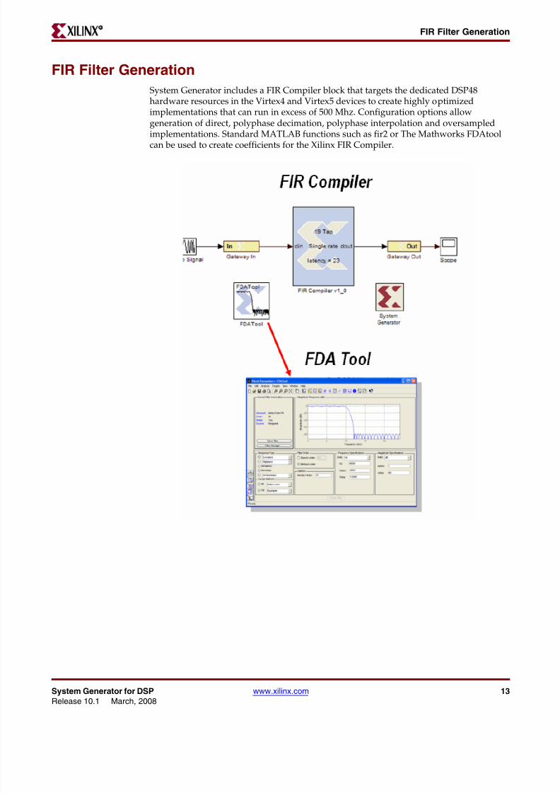
8112019 System Generator for DSP Getting Started
httpslidepdfcomreaderfullsystem-generator-for-dsp-getting-started 2293
22 wwwxilinxcom System Generator for DSPRelease 101 March 2008
Chapter 2 Installation R
version For example if the versions that are installed are 9201 and 101 and the currentlyselected version is 101 then entering xlVersion displays
Available System Generator installationsVersion 9201 in CXilinx9201DSP_ToolssysgenVersion 101 in CXilinx101DSP_Toolssysgen
Current version of System Generator is 101
Entering xlVersion 9201 switches the System Generator version to 9201
Occasionally it is necessary to restart MATLAB to make it possible to switch In this casethe response to entering xlVersion 101 looks like the following
Please restart MATLAB and run xlVersion 101 again to switch
When the switch succeeds xlVersion prints the following
Your System Generator has been switched Please restart MATLAB
If you install System Generator 101 after you install 9201 you need to install 101 again inorder to make xlVersion work
Once you switch System Generator version you need to switch to the right version of ISEin order to make System Generator work correctly
8112019 System Generator for DSP Getting Started
httpslidepdfcomreaderfullsystem-generator-for-dsp-getting-started 2393
System Generator for DSP wwwxilinxcom 23Release 101 March 2008
R
Chapter 3
Release Information
Release Notes 101
System Generator Enhancements
System Generator Project Navigator Integration
System Generator designs can now be more easily incorporated into a larger design insideof Project Navigator by using a new source type in Project Navigator The SystemGenerator design can also be launched from Project Navigator
DCM Support
System Generator now provides the option to automatically include a DCM in a designAlthough the optional DCM is abstracted away from the designer the generated designwill leverage DCMs available in the silicon
An alternative option exposes the clock ports at the top level for manual connection to aDCM
Dual Asynchronous-Clock Support for PLB46
This capability gives the designer additional flexibility by allowing the DSP andembedded processing portions of a design to run at different clock rates
Run Time Speed Improvements
bull Up to 2x faster first time initialization of a simulation
bull gt10x faster initialization when loading the Xilinx Blockset in the Simulink LibraryBrowser
M-Based HW Co-Simulation
System Generator models compiled for HW Co-Simulation can now be embeddedconfigured and utilized in a MATLAB M-code script allowing for calls into hardware to bemade from MATLAB
8112019 System Generator for DSP Getting Started
httpslidepdfcomreaderfullsystem-generator-for-dsp-getting-started 2493
24 wwwxilinxcom System Generator for DSPRelease 101 March 2008
Chapter 3 Release Information R
Xilinx DSP Blockset Enhancements
FFT 50
Update to existing block which now includes cyclic prefix insertion
FIR Compiler 32Update which now include support for Virtex II and Spartan 3A
Reset Generator
New block that produces synchronized downsampled reset signals which eliminates theneed to manually create these signals
CIC Compiler 11
New block now available in System Generator
Tool Flow and IntegrationSystem Generator 101 is compatible with the following tools
Tool Version
The Mathworks MATLABreg and Simulink 2007a and 2007b
Mentor Graphics ModelSimreg SE 63c
Synplicity Synplify Proreg 8804 (Requires a floating license forHardware Co-Simulation)
Xilinxreg AccelDSP 101
Xilinxreg ChipScope Pro 101
Xilinxreg EDK 101
Xilinxreg ISE 101
Xilinxreg ISE IP Update 101 IP Update 1
Xilinxreg ISE Simulator 101
8112019 System Generator for DSP Getting Started
httpslidepdfcomreaderfullsystem-generator-for-dsp-getting-started 2593
System Generator for DSP wwwxilinxcom 25Release 101 March 2008
Release Notes 9201R
Release Notes 9201
System Generator Enhancements
EDK 92 SP1 PLBv46 amp MB 70 Support
This release of System Generator supports Embedded Design Kit (EDK) Release 92SP1and the MicroBlaze PLB v46 bus interface As shown in the figure below when you exporta System Generator design as a MicroBlaze processor core (pcore) using the EDK Processor block you can choose to connect the pcore to the MicroBlaze v46 bus or the previouslysupported FSL (Fast Simplex Link) The PLB v46 is now the default choice
When you select the PLB v46 option the target MicroBlaze processor must have a PLBv46 bus properly connected to the DPLB interface and a proc_sys_reset module connectedto the system reset pin Also both the pcore PLB memory map and the PLB bus should runat the same operating frequency These requirements will be in place if you use the XPSBase System Builder to build the MicroBlaze processor
Specifying a PLB v46 Base Address When you select the PLB v46 (Processor Local Bus)option the bus address space will be automatically adjusted and minimized If you knowwhere you want the bus address space to start you enter the address and click LockOtherwise the base address will be automatically determined for you This Base Addressoption is not used with the FSL Bus Type
Note Software simulation is disabled in this release You can simulate the processorsubsystem within System Generator and Simulink by connecting a supported hardwareplatform to your host computer and using Hardware Co-Simulation See the topic UsingHardware Co-Simulation for details
Pcore Export Enhancements
The EDK Export Tool has been enhanced to provide the following new features
Asynchronous Software Drivers for FSLs
FSL-based pcores connect to the MicroBlaze processor using FIFOs It is possible for usersin XPS to connect one clock to the processor and another to the System Generator pcore In
the past if you did this there was a chance that data would be lostIn the release you can set your software drivers to work in polling mode Polling driverswill keep retrying (for a programmable number of times) to read or write data Pollingdrivers are less efficient but they are tolerant to clock differences between the Processorand Pcore
To configure the software driver in Xilinx Platform Studio (XPS) you select the menuSoftware gt Software Platform Settings to get the following dialog box shown below You
8112019 System Generator for DSP Getting Started
httpslidepdfcomreaderfullsystem-generator-for-dsp-getting-started 2693
26 wwwxilinxcom System Generator for DSPRelease 101 March 2008
Chapter 3 Release Information R
click on Drivers and if Sysgen-based FSL pcores are available driver parameters will bepresent as shown below Select SG_POLLING to be true to enable polling drivers
Export as Pcore Under Development
This feature works for both FSL- and PLB-based pcore export When a pcore is marked asPcore under development XPS will not cache the HDL produced for this pcore This isuseful when you are developing pcores in System Generator and testing them out in XPSYou can just enable this checkbox make changes in System Generator and compile in XPS
XPS always compiles the generated pcore so you donrsquot have to empty the XPS cache whichmay contain caches of other peripherals thus slowing down the compile of the final bitstream
Enable Custom Bus Interfaces
This feature works for both FSL- and PLB-based pcore export and allows you to createcustom bus interfaces that will be understood in XPS
8112019 System Generator for DSP Getting Started
httpslidepdfcomreaderfullsystem-generator-for-dsp-getting-started 2793
System Generator for DSP wwwxilinxcom 27Release 101 March 2008
Release Notes 9201R
Improved EDK Processor Bitstream Support
When you perform bitstream compilation on a System Generator design with an EDKProcessor block the imported EDK project and the shared memories sitting between theSystem Generator design and MicroBlaze processor are netlisted along with the SystemGenerator design and included in the resulting bitstream
System Generator also attempts to compile any active software programs inside theimported EDK project If the compilation of active software programs succeeds SystemGenerator invokes the data2bram utility to include the compiled software programs intothe resulting bitstream
Note No error or warning message is issued when System Generator encounters failures duringsoftware program compilation or when System Generator updates the resulting bitstream with thecompiled software programs
Once the bitstream is generated you can modify the software programs in the importedEDK project and use the following command to compile the software programs andupdate the System Generator bitstream without re-running Place amp Route
xlProcBlockCallbacks(updatebitstream [] xmp_file bit_file bmm_file)
wherebull xmp_file is the pathname to the imported EDK project file
bull bit_file is the pathname to the Sysgen bitstream file
bull bmm_file is the pathname of the back-annotated BMM file produced by Sysgenduring bitstream compilation
If the imported EDK project contains a BMM file named imported_edk_projectbmmSystem Generator creates a back-annotated BMM file namedimported_edk_project_bdbmm You should provide the later back-annotated BMMfile to the above command in order to update the bitstream properly
Spartan-3A DSP 1800A Starter Platform Support
System Generator now supports the Spartan-3A DSP 1800A Starter Platform for EthernetPoint-to-Point Hardware Co-Simulation
Spartan-3A DSP 3400A Development Platform Support
System Generator now supports the Spartan-3A DSP 3400A Development Platform forHardware Co-Simulation Both the Point-to-point Ethernet configuration as well as theNetwork-Based Ethernet configuration are supported
Simulation Speed Improvements
Simulation speed for designs created with the Xilinx DSP Blockset has been improvedsubstantially in System Generator 9201 This speedup is relative to the number of blocksin the design with large designs over 2000 blocks showing a 5x to 10x run timeimprovement The following Simulink solver settings must be used to achieve the
8112019 System Generator for DSP Getting Started
httpslidepdfcomreaderfullsystem-generator-for-dsp-getting-started 2893
28 wwwxilinxcom System Generator for DSPRelease 101 March 2008
Chapter 3 Release Information R
maximum simulation performance improvement These solver settings can beautomatically configured by typing the ldquoxlConfigureSolverrdquo command at the MATLABconsole
RTL Improvements
In this release if two or more Simulink Sub-systems are exactly the same including inputdata types and mask parameters only a single VHDL entity or Verilog module will begenerated then instantiated multiple times in the HDL code generated by SystemGenerator This optimization improves HDL logic synthesis runtime while reducing theamount of memory consumed by XST
New JTAG Cable Sharing Option
A new option called Shared cable for concurrent access has been added to the propertiesdialog box for the JTAG Co-Simulation block This option allows the JTAG cable to beshared with EDK XMD during a JTAG co-simulation
When the option is checked the JTAG co-simulation engine only acquires a lock on thecable access and then immediately releases the lock when the access completes Otherwisethe JTAG co-simulation engine holds the lock throughout the simulation Due to thesignificant overhead on locking and unlocking the cable this cable sharing option isdisabled by default and only enabled when you check the box
8112019 System Generator for DSP Getting Started
httpslidepdfcomreaderfullsystem-generator-for-dsp-getting-started 2993
System Generator for DSP wwwxilinxcom 29Release 101 March 2008
Release Notes 9201R
Xilinx DSP Blockset Enhancements
Convolutional Encoder v61
bull Support has been added for Spartan-3A DSP
Reed-Solomon Decoder v61bull Support has been added for Spartan-3A DSP
bull The Field Polynomial entry in the GUI is now entered as a decimal number ratherthan a binary string
Reed-Solomon Encoder v61
bull Support has been added for Spartan-3A DSP
bull The Field Polynomial entry in the GUI is now entered as a decimal number ratherthan a binary string
Viterbi Decoder v61
bull Support has been added for Spartan-3A DSP
Tool Flow and Integration
System Generator 9201 is compatible with the following tools
Known Issues
Known issues with this release can be found on the Xilinx web site at the followingaddress
httpwwwxilinxcomxlnxxil_ans_displayjspgetPagePath=29595
Tool Version
The Mathworks MATLABreg and Simulink 2006b and 2007a
Mentor Graphics ModelSimreg SE 61f
Synplicity Synplify Proreg 8804 (Requires a floating license for
Hardware Co-Simulation)Xilinxreg AccelDSP 9201
Xilinxreg ChipScope Pro 9203i
Xilinxreg EDK EDK 92 SP1
Xilinxreg ISE 9203i
Xilinxreg ISE IP Update 92i IP Update 1
Xilinxreg ISE Simulator 9203i
8112019 System Generator for DSP Getting Started
httpslidepdfcomreaderfullsystem-generator-for-dsp-getting-started 3093
30 wwwxilinxcom System Generator for DSPRelease 101 March 2008
Chapter 3 Release Information R
Release Notes 9200
System Generator Enhancements
Single DSP Tools Installer using Xilinx Unified Installer
All Xilinx DSP Tools now use a Unified Installer for software installation andconfiguration
System Generator MATLAB Selector
As part of the unified installation process this configuration feature allows the useradditional flexibility to specify which version of MATLABSimulink should be associatedwith a particular version of System Generator This is helpful for users who have morethan one version of MATLABSimulink or System Generator on their machine
Selectable Block Frequency for Hardware Co-Simulation
If you are using a Xilinx ML402 or ML506 platform at netlist time System Generator allowsyou to choose a clock frequency for the target design that is equal to or less than the systemclock frequency The following table outlines the frequencies that are available
Platform InterfaceSystem Clock
Frequency
Available
Frequencies
Xilinx ML402 JTAGPoint-to-point EthernetNetwork-based Ethernet
100 MHz 100 MHz
667 MHz
50 MHz
333 MHz
Xilinx ML506 Point-to-point EthernetNetwork-based Ethernet
200 MHz 100 MHz
667 MHz
50 MHz
333 MHz
8112019 System Generator for DSP Getting Started
httpslidepdfcomreaderfullsystem-generator-for-dsp-getting-started 3193
System Generator for DSP wwwxilinxcom 31Release 101 March 2008
Release Notes 9200R
As shown below you set the target clock frequency at compilation time by clicking theSettings button on the System Generator block dialog box then select the frequency in thepulldown menu
Clock Enable Fanout Reduction
A new mapping algorithm has been implemented that uses register duplication andplacement based on recursive partitioning of loads on high fanout nets This meansimproved FMAX on System Generator designs with large CE fanout
Although this feature is enabled in System Generator by default the fanout reductionoccurs downstream during the ISE mapping operation and the following MAP optionsmust be turned on
bull Perform Timing-Driven Packing and Placement on
bull Map Effort Level High
bull Register Duplication on
If you are using the ISE Project Navigator flow these MAP options are also on by defaultHowever if you are using the default System Generator netlisting flow you must turnthese MAP options on by modifying the bitstream opt file or by providing your own optfile
Shared Memory Stitching
Starting with this release if two Shared Memory blocks with the same name existanywhere in the design hierarchy then during netlisting the two blocks will be stitchedinto a single Shared Memory block If a single Shared Memory block exists then the inputand output ports of the block are pushed to the top-level of the design
If more than two Shared Memory blocks with the same name exist then an error occurs
This new stitching feature also applies to To FIFO and From FIFO block pairs with thesame name and To Register and From Register block pairs with the same name
2 Select
1 Click
8112019 System Generator for DSP Getting Started
httpslidepdfcomreaderfullsystem-generator-for-dsp-getting-started 3293
32 wwwxilinxcom System Generator for DSPRelease 101 March 2008
Chapter 3 Release Information R
For backward compatibility you can set the MATLAB global variablexlSgSharedMemoryStitch to ldquooffrdquo to bring System Generator back to the netlisting behavior before the 92 release For example from the MATLAB command line enter thefollowing
global xlSgSharedMemoryStitchxlSgSharedMemoryStitch = off
System Generator Requires a Simulink Variable-step Solver
Simulink divides simulation solvers into two types fixed-step and variable-step Bothtypes of solvers compute the next simulation time as the sum of the current simulationtime and a quantity known as the step size With a fixed-step solver the step size remainsconstant throughout the simulation By contrast with a variable-step solver the step sizecan vary from step to step depending on the models dynamics In particular a variable-step solver reduces the step size when a models states are changing rapidly to maintainaccuracy and increases the step size when the systems states are changing slowly in orderto avoid taking unnecessary steps
System Generator requires that you use a Variable-step solver for every Simulinksimulation The use of a Fixed-step solver is not supported and will be explicitlydisallowed in a future release Using a Fixed-step solver might result in an inaccurateSystem Generator simulation
As shown below to choose a Variable-step solver select Simulation gt ConfigurationParameters from the Simulink pulldown menu then choose Variable-step from theSolver options
1 Select
2 Select
3 Observe
8112019 System Generator for DSP Getting Started
httpslidepdfcomreaderfullsystem-generator-for-dsp-getting-started 3393
System Generator for DSP wwwxilinxcom 33Release 101 March 2008
Release Notes 9200R
Xilinx DSP Blockset Enhancements
DDS Compiler v2_0
bull Supports LogiCORE DDS Compiler 20
bull Support has been added for Spartan-3A DSP
bull New controls have been introduced to expose the rfd and rdy output ports Thisfeature has also been added to DDS Compiler v11
bull channel input port has been renamed channelsel to avoid confusion with the channeloutput port
bull Core initialization times have been significantly reduced both for DDS Compiler v11and DDS Compiler v20
FIR Compiler v3_1
bull Supports LogiCORE FIR Compiler 31
bull Faster simulation speeds when using re-loadable coefficients
bull Support for Rounding in the FIR Compiler core through the following newparameters on the Advanced Pane of the Parameters dialog box
diams Rounding mode List box with the following options
- Full_Precision
- Truncated_LSBS
- Non_Symmetric_Rounding_Down
- Non_Symmetric_Rounding_Up
- Convergent_Rounding_To_Even
- Convergent_Rounding_To_Odd
- Symmetric_Rounding_To_Zero
- Symmetric_Rounding_To_One- Symmetric_Rounding_To_Infinity
diams Output Width An editbox specifying the output width which is activated only ifthe Rounding mode is set to a value other than Full_Precision
diams Allow Rounding Approximation Check box that specifies if approximations can be allowed to save resources when using symmetric rounding
Help System Improvements
The System Generator Help System has gone through a major upgrade that includes a newHTML browser a new comprehensive index and full text search capability
8112019 System Generator for DSP Getting Started
httpslidepdfcomreaderfullsystem-generator-for-dsp-getting-started 3493
34 wwwxilinxcom System Generator for DSPRelease 101 March 2008
Chapter 3 Release Information R
Tool Flow and Integration
System Generator 9200 is compatible with the following tools
Known Issues
Known issues with this release can be found on the Xilinx web site at the followingaddress
httpwwwxilinxcomxlnxxil_ans_displayjspgetPagePath=29110
Tool Version
The Mathworks MATLABreg and Simulink 2006b and 2007a
Mentor Graphics ModelSimreg SE 61f
Synplicity Synplify Proreg 8804 (Requires a floating license forHardware Co-Simulation)
Xilinxreg AccelDSP 9200
Xilinxreg ChipScope Pro 9202i
Xilinxreg EDK EDK support is not available in this releaseof System Generator and is expected toreturn in the next service pack
Xilinxreg ISE 9202i
Xilinxreg ISE IP Update 92i IP Update 1Xilinxreg ISE Simulator 9202i
8112019 System Generator for DSP Getting Started
httpslidepdfcomreaderfullsystem-generator-for-dsp-getting-started 3593
System Generator for DSP wwwxilinxcom 35Release 101 March 2008
Release Notes 9101R
Release Notes 9101
System Generator Enhancements
New Technologies Supported
Spartantrade-3A DSP The new Spartantrade-3A DSP series targets cost-sensitive high-performance signal processing applications
Xilinx DSP Blockset Enhancements
FIR Compiler v3_0
bull Supports LogiCORE FIR Compiler 30
bull Support has been added for Spartan-3A DSP
bull Supports interpolated filter implementations
bull Maximum number of channels increased to 64
bull Maximum integer rate change increased to 64
bull Now exploits symmetry when interpolating by an even rate with an odd number ofcoefficients reducing resource utilization
DDS Compiler v1_1
bull Supports LogiCORE DDS Compiler 11
bull Support added for Virtextrade-5 and Spartantrade-3A
DSP48 Macro
bull Support added for DSP48A slice
bull The DSP48 Macro block provides a device independent abstraction for the DSP48DSP48E and DSP48A slices
DSP48A
bull Supports DSP48A slice
bull The DSP48A slice is unique to the Spartantrade-3A DSP family of FPGAs The DSP48Aslices support many independent functions including multiplier multiplieraccumulator (MACC) preaddersubtracter followed by a multiply-accumulatormultiplier followed by an adder wide bus multiplexers magnitude comparator orwide counter
8112019 System Generator for DSP Getting Started
httpslidepdfcomreaderfullsystem-generator-for-dsp-getting-started 3693
36 wwwxilinxcom System Generator for DSPRelease 101 March 2008
Chapter 3 Release Information R
Tool Flow and Integration
System Generator is compatible with the following tools
Migrating Designs Created in Previous Versions of Software
You must update v71 or earlier models to 9101 Conversion instructions are provided inthe next section that explain the process in detail To update a model you run a MATLABcommand xlUpdateModel that invokes a conversion script
Please be advised that the conversion script does not automatically save an old version of your modelas it updates the design nor save a new version of your model after conversion You can either makea back up copy of your model before running the conversion script or you can save the updatedmodel with a new name
Some models may require some manual modification after running the conversion script
The script will point out any necessary manual changes
Tool Version
The Mathworks MATLABreg and Simulink 2006a 2006b
Mentor Graphics ModelSimreg SE 61f
Synplicity Synplify Proreg 862 (Requires a floating license forHardware Co-Simulation)
Xilinxreg AccelDSP 9101
Xilinxreg ChipScope Pro 9103i
Xilinxreg EDK 9101i
Xilinxreg ISE 9103i
Xilinxreg ISE IP Update 91i IP Update 2
Xilinxreg ISE Simulator 9103i
8112019 System Generator for DSP Getting Started
httpslidepdfcomreaderfullsystem-generator-for-dsp-getting-started 3793
System Generator for DSP wwwxilinxcom 37Release 101 March 2008
Upgrading a Xilinx System Generator ModelR
Upgrading a Xilinx System Generator Model
Upgrading v2x and Prior Models
If you are upgrading from versions of System Generator earlier than v31 you must obtainSystem Generator v7x and update your models to v7x before you can update them to
v9101
Upgrading v3x v6x and v7x Models
This section describes the process of upgrading a Xilinx System Generator v3x v6x orv7x model to work with v9101
Note Any reference to v3x or v6x in this section can be used interchangeably with v7x
The basic steps for upgrading a v7x model to v9101 is as follows 1) Save a backup copyof your v71 model and user-defined libraries that your model uses 2) RunxlUpdateModel on any libraries first and then on your model 3) Read the reportproduced by xlUpdateModel and follow the instructions 4) Check that your model runs
under v9101These steps are described in greater detail below
1 Save a backup copy of your v71 model and user-defined libraries that your modeluses
2 Run the xlUpdateModel Function
From the MATLAB console cd into the directory containing your model If the nameof your model is designNamemdl type xlUpdateModel(designName)
The xlUpdateModel function performs the following tasks
diams Updates each block in your v7x design to a corresponding v9101 block withequivalent settings
diams Writes a report explaining all of the changes that were made This reportenumerates changes you may need to make by hand to complete the update
In most cases xlUpdateModel produces an equivalent v9101 model Howeverthere are a few constructs that may require you to edit your model It is important thatyou read the report and follow the remaining steps in this section
3 Read the xlUpdateModel report and Follow the Instructions
If the report contains the issues listed below manual intervention will be required tocomplete the conversion
a Xilinx System Generator v7x models containing removed blocks
The following blocks have been removed from System Generator CIC ClearQuantization Error Digital Up Converter J83 Modulator Quantization Error
Sync
b Xilinx System Generator v7x Models that Contain Deprecated Blocks
The DDSv40 block still exist in System Generator but has been deprecated
c Xilinx System Generator v7x Models Utilizing Explicit Sample Periods
The explicit sample period fields have been removed from most non-source blocksin System Generator v9101 Source blocks (eg Counter block) continue to allowthe specification of explicit sample periods When upgrading models containing
8112019 System Generator for DSP Getting Started
httpslidepdfcomreaderfullsystem-generator-for-dsp-getting-started 3893
38 wwwxilinxcom System Generator for DSPRelease 101 March 2008
Chapter 3 Release Information R
feedback loops Assert blocks must typically be added by hand afterxlUpdateModel has been run This is necessary in order to help System Generatordetermine appropriate rates and types for the path The following error message isan indication that an Assert block is required
ldquoThe data rates could not be established for the feedback paths through this blockYou may need to add Assert blocks to instruct the systemrdquo
In such a case you should augment each feedback loop with an Assert block andspecify rates and types explicitly on this block
The update script will annotate the converted model wherever the v71 modelasserted an explicit period In the converted model you will most often not needto insert Assert blocks To find out where you need them try to update thediagram (the Update Diagram control is under the Edit menu) If rates do notresolve you will need to insert one or more Assert blocks
The update script can be configured to automatically insert Assert blocksimmediately following blocks configured with an explicit sample period settingTo use this option run the following command
xlUpdateModel(designNameassert)
4 Save and Close the updated model
If you did not previously make a backup copy of the old model you can save theupdated model under a new name to preserve the old model
5 Verify that Your model Runs Under System Generator v9101
If you have followed the instructions in the previous steps your model should runwith System Generator v9101 Open the model with System Generator v9101and run it
Examples
Example 1
gtgt xlUpdateModel(my_model_name)
Update the file my_model_namemdl that is located in the current MATLAB workingdirectory
Example 2
gtgt xlUpdateModel(my_model_namelib)
Update the file my_model_namemdl that is located in the current MATLAB workingdirectory along with the libraries that are associated with the model
Example 3
gtgt xlUpdateModel(my_model_nameassertrsquo)
Update the file my_model_namemdl that is located in the current MATLAB workingdirectory Add Assert blocks where necessary
8112019 System Generator for DSP Getting Started
httpslidepdfcomreaderfullsystem-generator-for-dsp-getting-started 3993
System Generator for DSP wwwxilinxcom 39Release 101 March 2008
R
Chapter 4
Getting Started
Introduction
This Getting Started training consists of six short lessons that introduce you to majorfeatures of System Generator for DSP Each lesson takes less than 10 minutes to read and isfollowed by one or more hands-on lab exercises The lab exercise folders are located in theSystem Generator software tree and contain data files and step-by-step instructions
If you have System Generator installed on your computer you can complete each labexercise at your own pace and on your own time schedule If you do not have SystemGenerator installed you can access this free training in a recorded e-learning formatthrough the Xilinx web site at the following locationhttpwwwxilinxcomsupporttrainingrelsystem-generatorhtm
The lessons contained in this Getting Started are as follows
bull Lesson 1 - Design Creation Basics Introduces the basics of creating andimplementing a DSP design using System Generator
bull Lesson 2 - Fixed Point and Bit Operations Covers the use of the System Generatorrouting blocks for extracting and manipulating the individual bits of a fixed-pointsignal
bull Lesson 3 - System Control Covers the preferred methods for using System Generator
to create finite state machines logical control conditions and the handling of burstydata typical of FFT and filtering operations
bull Lesson 4 - Multi-Rate Systems Shows the proper way to create multi-rate systemsusing upsampling and downsampling of data
bull Lesson 5 - Using Memories Covers proper usage of the Xilinx block RAM resourcesand the DSP blocks available for building DSP designs targeting Xilinx RAMs
bull Lesson 6 - Designing Filters Discusses methods for creating efficient FIR filters in theXilinx devices use of the FIR Compiler block for filter implementation and use of theFDATool for filter design
8112019 System Generator for DSP Getting Started
httpslidepdfcomreaderfullsystem-generator-for-dsp-getting-started 4093
40 wwwxilinxcom System Generator for DSPRelease 101 March 2008
Chapter 4 Getting Started R
Lesson 1 - Design Creation Basics
The System Generator Design Flow
System Generator works within the Simulink model-based design methodology Often an executable spec iscreated using the standard Simulink block sets This spec can be designed using floating-point numerical precision
and without hardware detail Once the functionality and basic dataflow issues have been defined SystemGenerator can be used to specify the hardware implementation details for the Xilinx devices System Generatoruses the Xilinx DSP blockset for Simulink and will automatically invoke Xilinx Core Generator to generate highly-optimized netlists for the DSP building blocks System Generator can execute all the downstream implementationtools to product a bitstream for programming the FPGA An optional testbench can be created using test vectorsextracted from the Simulink environment for use with ModelSim or the Xilinx ISE Simulator
8112019 System Generator for DSP Getting Started
httpslidepdfcomreaderfullsystem-generator-for-dsp-getting-started 4193
System Generator for DSP wwwxilinxcom 41Release 101 March 2008
Lesson 1 - Design Creation BasicsR
The Xilinx DSP Blockset
The Xilinx DSP blockset is accessed via the Simulink Library browser which can be launched from the standardMATLAB toolbar The blocks are separated into sub-categories for easier searching One sub-category ldquoIndexrdquoincludes all the block and is often the quickest way to access a block you are already familiar with Over 90 DSP building blocks are available for constructing you DSP system
8112019 System Generator for DSP Getting Started
httpslidepdfcomreaderfullsystem-generator-for-dsp-getting-started 4293
42 wwwxilinxcom System Generator for DSPRelease 101 March 2008
Chapter 4 Getting Started R
Defining the FPGA Boundary
System Generator works with standard Simulink models Two blocks called ldquoGateway Inrdquo and ldquoGateway Outrdquodefine the boundary of the FPGA from the Simulink simulation model The Gateway In block converts the floatingpoint input to a fixed-point number You double-click on the block to bring up the properties editor which is wherethe fixed-point number can be fully specified
8112019 System Generator for DSP Getting Started
httpslidepdfcomreaderfullsystem-generator-for-dsp-getting-started 4393
System Generator for DSP wwwxilinxcom 43Release 101 March 2008
Lesson 1 - Design Creation BasicsR
Adding the System Generator Token
Every System Generator diagram requires that at least one System Generator token be placed on the diagram This block is not connected to anything but serves to drive the FPGA implementation process The property editor forthis block allows specification of the target netlist device performance targets and system period SystemGenerator will issue an error if this block is absent
8112019 System Generator for DSP Getting Started
httpslidepdfcomreaderfullsystem-generator-for-dsp-getting-started 4493
44 wwwxilinxcom System Generator for DSPRelease 101 March 2008
Chapter 4 Getting Started R
Creating the DSP Design
Once the FPGA boundaries have been established using the Gateway blocks the DSP design can be constructedusing blocks from the Xilinx DSP blockset Standard Simulink blocks are not supported for use within the GatewayIn Gateway out blocks You will find a rich set of filters FFTs FEC cores memories arithmetic logical and bitwise blocks available for use in constructing DSP designs Each of these blocks are cycle and bit accurate
8112019 System Generator for DSP Getting Started
httpslidepdfcomreaderfullsystem-generator-for-dsp-getting-started 4593
System Generator for DSP wwwxilinxcom 45Release 101 March 2008
Lesson 1 - Design Creation BasicsR
Generating the HDL Code
Once the design is completed the hardware implementation files can be generated using the Generate buttonavailable on the System Generator token properties editor One option is to select HDL Netlist which allows theFPGA implementation steps of RTL synthesis and place and route to be performed interactively using tool specificuser interfaces Alternatively you can select Bitstream as the Compilation target and System Generator willautomatically perform all implementation steps
If the Create Testbench option is selected then System Generator will save and write test vector files that areextracted from the Simulink simulation and generate an HDL testbench and script files for ModelSim This is anoptional step that simply verifies that the generated hardware is functionally equivalent to the Simulink simulationThe script files must be used with ModelSim interactively
8112019 System Generator for DSP Getting Started
httpslidepdfcomreaderfullsystem-generator-for-dsp-getting-started 4693
46 wwwxilinxcom System Generator for DSPRelease 101 March 2008
Chapter 4 Getting Started R
Model-Based Design using System Generator
Model-based design refers the design practice of creating a high-level executable specification using the standardSimulink blocksets or MATLAB first to define the desired functional behavior with minimal hardware detail Thisexecutable spec is then used as a reference model while the hardware representation is specified using the XilinxDSP blockset
8112019 System Generator for DSP Getting Started
httpslidepdfcomreaderfullsystem-generator-for-dsp-getting-started 4793
System Generator for DSP wwwxilinxcom 47Release 101 March 2008
Lesson 1 - Design Creation BasicsR
Creating Input Vectors using MATLAB
Simulink is built on top of MATLAB allowing the use of the full MATLAB language for input signal generation andoutput analysis You can use the ldquoFrom Workspacerdquo and ldquoTo Workspacerdquo blocks from the Simulink Source andSink libraries Input values must be specified as an n rows x 2 column matrix where the first column is thesimulation time and the second column includes the input values This is a very popular way to generate inputvectors for System Generator designs
8112019 System Generator for DSP Getting Started
httpslidepdfcomreaderfullsystem-generator-for-dsp-getting-started 4893
48 wwwxilinxcom System Generator for DSPRelease 101 March 2008
Chapter 4 Getting Started R
Lesson 1 Summary
bull You partition the FPGA design from the Simulink ldquosystemrdquo using Gateway In Gateway Out blocks
bull You always include a System Generator token on each sheet
bull You should only use blocks from the Xilinx DSP blockset between the gateway blocks
bull You should consider using the From To workspace blocks to use MATLAB for inputgeneration and output analysis
Lab Exercise Using Simulink
In this lab you will learn the basics of Simulink You will use a Simulink blockset togenerate a simple design and take it through simulation You will then change thesampling settings to see its effect on the output You will then learn how to create asubsystem
The lab instructions are located in the System Generator software tree at the followingpathname
ltsysgen_treegtexamplesgetting_started_traininglab1lab1pdf
Lab Exercise Getting Started with System Generator
This lab introduces you to the basic concepts of creating a design using System Generatorwithin the model-based design flow provided through Simulink The design is a simplemultiply-add circuit
The lab instructions and lab design are located in the System Generator software tree at thefollowing pathname
ltsysgen_treegtexamplesgetting_started_traininglab2
Lab Instructions
Lab Design
8112019 System Generator for DSP Getting Started
httpslidepdfcomreaderfullsystem-generator-for-dsp-getting-started 4993
System Generator for DSP wwwxilinxcom 49Release 101 March 2008
Lesson 2 - Fixed Point and Bit OperationsR
Lesson 2 - Fixed Point and Bit Operations
Fixed-Point Numeric Precision
System Generator supports three data types Unsigned for positive only DSP operations Signed which is tworsquoscomplement used for DSP operations that involve negative numbers and Boolean for 1-bit control signals Each
block will typically have quantization parameters The initial quantization is defined by the Gateway In blocks
8112019 System Generator for DSP Getting Started
httpslidepdfcomreaderfullsystem-generator-for-dsp-getting-started 5093
50 wwwxilinxcom System Generator for DSPRelease 101 March 2008
Chapter 4 Getting Started R
System Generator Fixed-Point Quantization
Xilinx fixed-point data types are defined by specifying the total number of bits then specifying the location of the binary point The difference which represents the number of bits to the left of the binary point are the integer bitsfor ufixed numbers and the integer bits plus sign bit for signed numbers Xilinx FPGAs do not require that fixed-point numbers fall in pre-defined 8 bit boundaries as is the case with DSP processors The logic can grow bit-by-bitto accommodate the required fixed-point precision
8112019 System Generator for DSP Getting Started
httpslidepdfcomreaderfullsystem-generator-for-dsp-getting-started 5193
System Generator for DSP wwwxilinxcom 51Release 101 March 2008
Lesson 2 - Fixed Point and Bit OperationsR
Overflow and Round Modes
System Generator supports the overflow modes Wrap Saturate and Flag as error Wrap is the default because ithas the least cost in hardware Saturate requires System Generator to insert logic to perform that operation andtherefore should only be used when necessary for the application
System Generator supports Truncate and Round of the LSB during the quantization process Similar to the Wrap
mode for overflow mode Truncate has minimal hardware cost and is the default Specifying the Round moderequires System Generator to insert extra logic and should be used when only necessary for the application
8112019 System Generator for DSP Getting Started
httpslidepdfcomreaderfullsystem-generator-for-dsp-getting-started 5293
52 wwwxilinxcom System Generator for DSPRelease 101 March 2008
Chapter 4 Getting Started R
Bit-Level Operations
In a real DSP hardware system not all operations can be expressed mathematically Often a signal must be accessed by its individual bits System Generator supports a set of bit-level operations that allow the reinterpret combiningconversion and extraction of the individual bits of a signal This can be used to pad unpad and slice off the bits ofa signal with a high degree of control These blocks do not use any hardware resources
8112019 System Generator for DSP Getting Started
httpslidepdfcomreaderfullsystem-generator-for-dsp-getting-started 5393
System Generator for DSP wwwxilinxcom 53Release 101 March 2008
Lesson 2 - Fixed Point and Bit OperationsR
The Reinterpret Block
The Reinterpret block forces the bits of a signal to a new type without regard for the numerical value or location ofthe decimal point This block does not change the number of bits of a signal but simply reinterprets the data typeFor example if the number 4 is represented as an unsigned [4 1] it is 1000 If this number is reinterpreted to beunsigned [4 0] the 1000 is now 8
8112019 System Generator for DSP Getting Started
httpslidepdfcomreaderfullsystem-generator-for-dsp-getting-started 5493
54 wwwxilinxcom System Generator for DSPRelease 101 March 2008
Chapter 4 Getting Started R
The Convert Block
The Convert block changes the quantization of a number but not the value This block can alter the number of bitsused to represent a number It can be used to convert a signed type to an unsigned type and visa versa Often theConvert block is used to truncate the output fractional bits after a multiplication operation
8112019 System Generator for DSP Getting Started
httpslidepdfcomreaderfullsystem-generator-for-dsp-getting-started 5593
System Generator for DSP wwwxilinxcom 55Release 101 March 2008
Lesson 2 - Fixed Point and Bit OperationsR
The Concat Block
The Concat block concatenates two inputs into a single output at the bit level This block has two input ports thatare labeled hi and lo The hi port occupies the MSBrsquos and the lo input occupies the LSBrsquos of the output signalThis block is useful for zero padding the MSBs or LSBs of a signal
8112019 System Generator for DSP Getting Started
httpslidepdfcomreaderfullsystem-generator-for-dsp-getting-started 5693
56 wwwxilinxcom System Generator for DSPRelease 101 March 2008
Chapter 4 Getting Started R
Slice Block
The Slice block is used to access individual bits of a quantized number This block provides several mechanisms bywhich the sequence of bits can be specified If the input type is known at the time of parameterization the variousmechanisms do not offer any gain in functionality If however a Slice block is used in a design where the input datawidth or binary point position are subject to change the variety of mechanisms becomes useful For example the block can be configured to always extract only the top bit of the input or only the integer bits or only the first threefractional bits
8112019 System Generator for DSP Getting Started
httpslidepdfcomreaderfullsystem-generator-for-dsp-getting-started 5793
System Generator for DSP wwwxilinxcom 57Release 101 March 2008
Lesson 2 - Fixed Point and Bit OperationsR
The BitBasher Block
The BitBasher block provides a textual method based on Verilog syntax for working with the signals at the bitlevel This block supports concatenation and slicing if the input signal to create an output It also allows foraugmentation with constants The BitBasher block supports up to 4 outputs that are inferred by the expressions
8112019 System Generator for DSP Getting Started
httpslidepdfcomreaderfullsystem-generator-for-dsp-getting-started 5893
58 wwwxilinxcom System Generator for DSPRelease 101 March 2008
Chapter 4 Getting Started R
Lesson 2 Summary
bull Quantization and overflow options are available when the output of a block is userdefined
bull Quantization occurs when the number of fractional bits is insufficient to represent thefractional portion of a value
bull Overflow occurs when a value lies outside the representable rangebull Bit picking blocks allow combining of multiple buses into a single bus force a
conversion of data type without changing the number of bits extract bits and convertthe number into different format
bull The BitBasher block allows bit manipulation and augmentation through textualspecification based in Verilog
Lab Exercise Signal Routing
In this lab you will design and verify padding and unpadding logic using the SystemGenerator signal routing blocks
The lab instructions are located in the System Generator software tree at the followingpathname
ltsysgen_treegtexamplesgetting_started_traininglab3lab3pdf
8112019 System Generator for DSP Getting Started
httpslidepdfcomreaderfullsystem-generator-for-dsp-getting-started 5993
System Generator for DSP wwwxilinxcom 59Release 101 March 2008
Lesson 3 - System ControlR
Lesson 3 - System Control
Controlling a DSP System
When you develop a DSP system in hardware some level of control is usually required This may include statedependent behavior or simply performing operations such as filter coefficient updating System-level control may
also be needed for controlling bursty data such as non-streaming FFTs
8112019 System Generator for DSP Getting Started
httpslidepdfcomreaderfullsystem-generator-for-dsp-getting-started 6093
60 wwwxilinxcom System Generator for DSPRelease 101 March 2008
Chapter 4 Getting Started R
The MCode Block
The MCode block supports the use of MATLAB for implementing state dependent and branch conditional controloperations This block is not suitable for MATLAB that describes an algorithmic operation such as a FIR filter orMatrix inverse The Xilinx AccelDSP tool can be used in these cases The MCode block provides a convenient andefficient method for implementing state machines and complex muxing conditions This is the recommended wayto implement a finite state machine in System Generator
8112019 System Generator for DSP Getting Started
httpslidepdfcomreaderfullsystem-generator-for-dsp-getting-started 6193
System Generator for DSP wwwxilinxcom 61Release 101 March 2008
Lesson 3 - System ControlR
The Xilinx ldquoxl_staterdquo Data Type
When implementing a state machine using the MCode block a Xilinx-provided MATLAB function called ldquoxl_staterdquomust be used to initialize a persistent variable This function has two arguments the first is the initial condition thesecond is the quantization of the assigned variable For example if your state machine has 6 states you need aquantization of 4-bits unsigned
8112019 System Generator for DSP Getting Started
httpslidepdfcomreaderfullsystem-generator-for-dsp-getting-started 6293
62 wwwxilinxcom System Generator for DSPRelease 101 March 2008
Chapter 4 Getting Started R
State Machine Example
The figure below shows a simple 2-state FSM This can be easily extended to more states Notice that a variablecalled ldquostaterdquo is declared to be persistent and is initialized to 2 bits unsigned using the ldquoxl_staterdquo function Aswitch-case statement is then used to decode the inputs branch to the next state and assign the outputs
8112019 System Generator for DSP Getting Started
httpslidepdfcomreaderfullsystem-generator-for-dsp-getting-started 6393
System Generator for DSP wwwxilinxcom 63Release 101 March 2008
Lesson 3 - System ControlR
The Expression Block
The Expression block performs a bitwise not and or amp xor on two input signals The inputs can have a word lengthgreater than 1 In cases where the two inputs have different word lengths the binary points are matched up andthen an element-by-element boolean operation is performed This block provides a useful way to implement logicalcontrol in a DSP system
8112019 System Generator for DSP Getting Started
httpslidepdfcomreaderfullsystem-generator-for-dsp-getting-started 6493
64 wwwxilinxcom System Generator for DSPRelease 101 March 2008
Chapter 4 Getting Started R
Reset and Enable Ports
Most System Generator blocks that include memory or storage provide options to expose the reset and clock enableports If un-selected these ports are automatically connected to the final hardwares global reset and clock enable orDCM schemes Exposing these ports on the System Generator block creates a condition where the block is reset orenabled when either the global signals or the local signals assert TRUE You should use these ports if greater controlover these functions is required in the DSP system
8112019 System Generator for DSP Getting Started
httpslidepdfcomreaderfullsystem-generator-for-dsp-getting-started 6593
System Generator for DSP wwwxilinxcom 65Release 101 March 2008
Lesson 3 - System ControlR
Bursty Data
Several of the more complex DSP blocks offered in the Xilinx DSP blockset result in ldquoburstyrdquo data For example thenon-streaming FFT requires several clock cycles to process the input data prior to generating valid output data Inthese cases these blocks include data flow control ports that must be used in the DSP system These ports provide basic push mode dataflow control They consist of a vin port which indicates that valid data is available at theinputs and vout which indicates that valid data is available at the outputs
8112019 System Generator for DSP Getting Started
httpslidepdfcomreaderfullsystem-generator-for-dsp-getting-started 6693
66 wwwxilinxcom System Generator for DSPRelease 101 March 2008
Chapter 4 Getting Started R
Lesson 3 Summary
bull Use the MCode block for state machines and branch conditional logic
bull Use the Expression block to implement logical control at the bit level
bull Storage elements have the ability to include optional reset and clock enable pins thatcan be connected in System Generator
bull Blocks that operate on bursty data include data flow control pins called vin and vout
Lab Exercise System Control
In this lab you will be creating a simple state machine using the MCode block to detect asequence of binary values ldquo1011rdquo The FSM needs to be able to detect multipletransmissions as well ie ldquo10111011rdquo
The lab data and instructions are located in the System Generator software tree at thefollowing pathname
ltsysgen_treegtexamplesgetting_started_traininglab4
Lab InstructionsLab Data
8112019 System Generator for DSP Getting Started
httpslidepdfcomreaderfullsystem-generator-for-dsp-getting-started 6793
System Generator for DSP wwwxilinxcom 67Release 101 March 2008
Lesson 4 - Multi-Rate SystemsR
Lesson 4 - Multi-Rate Systems
Creating Multi-Rate Systems
The following illustration shows a typical base-station receiver The tower has multiple antennas to providesectored coverage of the area The diagram shows that this results in two receiver channels In each of these
channels there is some form of complex mixing resulting in real and imaginary channels
Often DSP systems such as this will down sample the input signals prior to the digital filtering steps performedduring equalization and demodulation Doing so can simplify the filter design and hardware significantly Thesesystems are referred to as ldquomulti-raterdquo systems
8112019 System Generator for DSP Getting Started
httpslidepdfcomreaderfullsystem-generator-for-dsp-getting-started 6893
68 wwwxilinxcom System Generator for DSPRelease 101 March 2008
Chapter 4 Getting Started R
Up and Down Sampling Blocks
System Generator includes Up Sample and Down Sample blocks that change the system sample rate The UpSample block adds additional samples to the signal to achieve the desired rate change The value of these newsamples is either zero or the value of the last actual sample depending on the block options The Down Sample block simply discards samples until it achieves the desired rate change For example downsample by 3 means todiscard 2 out of every 3 samples
8112019 System Generator for DSP Getting Started
httpslidepdfcomreaderfullsystem-generator-for-dsp-getting-started 6993
System Generator for DSP wwwxilinxcom 69Release 101 March 2008
Lesson 4 - Multi-Rate SystemsR
Rate Changing Functional Blocks
In addition to the straightforward ldquoUp Samplerdquo and ldquoDown Samplerdquo blocks System Generator also provides ratechanging functional blocks that is blocks that also perform a specific function The Parallel to Serial block will upsample the Serial to Parallel block will down sample the FIR Compiler if using a resource-shared multiplier willdown sample and the TDM block will up sample
8112019 System Generator for DSP Getting Started
httpslidepdfcomreaderfullsystem-generator-for-dsp-getting-started 7093
70 wwwxilinxcom System Generator for DSPRelease 101 March 2008
Chapter 4 Getting Started R
Viewing Rate Changes in Simulink
Simulink supports viewing different sample times as different colors which is fully supported for System Generator blocks To enable the Sample Time Colors feature select the pulldown menu Format gt Sample Time Colors TheSimulink tool does not automatically recolor the model with each change you make to it so you must select Edit gtUpdate Diagram to explicitly update the model coloration To return to your original coloring disable the sampletime coloration by again choosing Sample Time Colors
8112019 System Generator for DSP Getting Started
httpslidepdfcomreaderfullsystem-generator-for-dsp-getting-started 7193
System Generator for DSP wwwxilinxcom 71Release 101 March 2008
Lesson 4 - Multi-Rate SystemsR
Debugging Tools
System Generator provides 3 debugging utilities to assist in debugging complex multi-rate systems
The Sample Time (ST) probe can be connected to any System Generator signal then to a Simulink ldquodisplayrdquo blockfrom the ldquoSinksrdquo library The sample time for the connected net will appear in the display
The clk probe is not connected to any inputs but only to a scope output It displays the master clock This can beused with the Clock Enable Probe to display the behavior of the clock enable signal at various points in the downsampling
8112019 System Generator for DSP Getting Started
httpslidepdfcomreaderfullsystem-generator-for-dsp-getting-started 7293
72 wwwxilinxcom System Generator for DSPRelease 101 March 2008
Chapter 4 Getting Started R
Sample Period ldquoRulesrdquo
The illustration below is an example of a multi-rate system that demonstrates how the Simulink System Period can be calculated and entered into the System Generator token GUI
If you get it wrong there is a sampling period analyzer that automatically determines the appropriate sampleperiod and prompts you to update the GUI
8112019 System Generator for DSP Getting Started
httpslidepdfcomreaderfullsystem-generator-for-dsp-getting-started 7393
System Generator for DSP wwwxilinxcom 73Release 101 March 2008
Lesson 4 - Multi-Rate SystemsR
Lab Exercise Multi-Rate Systems
In this lab you will be exploring the effects of the rate changing blocks available in SystemGenerator These blocks include Upsample Downsample Serial to Parallel and Parallel toSerial
The lab instructions and lab design are located in the System Generator software tree at the
following pathnameltsysgen_treegtexamplesgetting_started_traininglab5
Lab Instructions
Lab Design
8112019 System Generator for DSP Getting Started
httpslidepdfcomreaderfullsystem-generator-for-dsp-getting-started 7493
74 wwwxilinxcom System Generator for DSPRelease 101 March 2008
Chapter 4 Getting Started R
Lesson 5 - Using Memories
Block vs Distributed RAM
Xilinx FPGAs offer two distinct memory options Block RAM and Distributed RAM Block RAM uses dedicatedon-chip hardware resources and represents the most area-efficient RAM implementation Block RAMs offer high
performance but due to their fixed location on the chip may incur slightly larger routing delays Distributed RAMuses the lookup tables in the FPGA slices to implement memory and in doing so will subtract from the slicesavailable for logical operations Because Distributed RAM can be located anywhere throughout the chip routingdelays can be minimized and slightly higher performance can be achieved Distributed RAM is an excellent optionfor small FIFOs
8112019 System Generator for DSP Getting Started
httpslidepdfcomreaderfullsystem-generator-for-dsp-getting-started 7593
System Generator for DSP wwwxilinxcom 75Release 101 March 2008
Lesson 5 - Using MemoriesR
Initializing RAMs and ROMs
The RAM and ROM blocks can be initialized to a 1xn vector that matches the depth of the RAM MATLAB is usedto set the initial value vector Any MATLAB statement can be used that results in a 1xn vector including the filereading commands such as imread auread wavread and load
8112019 System Generator for DSP Getting Started
httpslidepdfcomreaderfullsystem-generator-for-dsp-getting-started 7693
8112019 System Generator for DSP Getting Started
httpslidepdfcomreaderfullsystem-generator-for-dsp-getting-started 7793
System Generator for DSP wwwxilinxcom 77Release 101 March 2008
Lesson 5 - Using MemoriesR
System Generator ROM Blocks
The ROM block supports an implementation in either Block- or Distributed RAM and is initialized through aMATLAB command The signal connected to the address port must be unsigned with no fractional bits
8112019 System Generator for DSP Getting Started
httpslidepdfcomreaderfullsystem-generator-for-dsp-getting-started 7893
78 wwwxilinxcom System Generator for DSPRelease 101 March 2008
Chapter 4 Getting Started R
The Delay Block
The Delay block is used to synchronize dataflow through the FPGA This block maps to a highly-efficient shiftregister structure built from a slice lookup table called an SRL16 that is 85 smaller than using registers
8112019 System Generator for DSP Getting Started
httpslidepdfcomreaderfullsystem-generator-for-dsp-getting-started 7993
System Generator for DSP wwwxilinxcom 79Release 101 March 2008
Lesson 5 - Using MemoriesR
The FIFO Block
The FIFO block supports both Block RAM and Distributed RAM implementations Depths up to 64K are supportedThree output flags are supported empty full and full The full flag is set depending on a bit widthspecification One bit will be zero until the FIFO is 50 full then it will set to5 Two bits will be zero until 20 fullthen 25 5 and 75
8112019 System Generator for DSP Getting Started
httpslidepdfcomreaderfullsystem-generator-for-dsp-getting-started 8093
80 wwwxilinxcom System Generator for DSPRelease 101 March 2008
Chapter 4 Getting Started R
Lab Exercise Using Memories
In this lab you will learn how to use a Xilinx ROM block to implement a LUT-basedoperation such as an Arcsin using Block RAM or Distributed RAM This provides anefficient implementation for trig and math functions with inputs that can be quantized to10 bits or less
The lab instructions and lab design are located in the System Generator software tree at thefollowing pathname
ltsysgen_treegtexamplesgetting_started_traininglab6
Lab Instructions
Lab Design
8112019 System Generator for DSP Getting Started
httpslidepdfcomreaderfullsystem-generator-for-dsp-getting-started 8193
System Generator for DSP wwwxilinxcom 81Release 101 March 2008
Lesson 6 - Designing FiltersR
Lesson 6 - Designing Filters
Introduction
Digital filters are a common DSP operation and especially well suited to implementation in FPGAs High-performance applications benefit greatly from parallel filters that can return a results on every clock cycle The
Virtex 5 device includes up to 550 parallel multipliers The FIR Compiler is designed to use these multipliers in themost efficient manner for creating commonly used FIR filters An alternative implementation is available calledldquodistributed arithmeticrdquo that creates FIR filters without using multipliers by employing a shift-add technique Thiscan be used for smaller devices when the available multipliers have been allocated to other functions
8112019 System Generator for DSP Getting Started
httpslidepdfcomreaderfullsystem-generator-for-dsp-getting-started 8293
82 wwwxilinxcom System Generator for DSPRelease 101 March 2008
Chapter 4 Getting Started R
The Virtex DSP48 Math Slice
The Virtextrade family introduces a high-performance arithmetic unit along with a multiplier the low-power DSP48slice The following figure is a detailed diagram of the DSP48 structure The DSP48 slice consists of four mainsections (1) IO registers (2) signed multiplier (3) three-input addersubtractor and (4) OPMODE multiplexers
8112019 System Generator for DSP Getting Started
httpslidepdfcomreaderfullsystem-generator-for-dsp-getting-started 8393
System Generator for DSP wwwxilinxcom 83Release 101 March 2008
Lesson 6 - Designing FiltersR
FIR Compiler Block
The Xilinx Fir Compiler v1_0 block implements a high speed MAC based FIR filter It accepts a stream of input dataand computes filtered output with a fixed delay based on the filter configuration The FIR Compiler supportsgeneration of resource shared or parallel FIR structures and polyphase decimation and interpolation structuresAlso supported is oversampling Coefficients are specified using MATLAB commands
8112019 System Generator for DSP Getting Started
httpslidepdfcomreaderfullsystem-generator-for-dsp-getting-started 8493
84 wwwxilinxcom System Generator for DSPRelease 101 March 2008
Chapter 4 Getting Started R
Creating Coefficients with FDATool
The Mathworks FDATool is a graphical filter design program that can be used to generate coefficients for the FIRCompiler block
8112019 System Generator for DSP Getting Started
httpslidepdfcomreaderfullsystem-generator-for-dsp-getting-started 8593
System Generator for DSP wwwxilinxcom 85Release 101 March 2008
Lesson 6 - Designing FiltersR
Using FDA Tool Coefficients
Once a suitable filter response has been designed you simply export the coefficients to the workspace using theFile gt Export command The workspace variable can then be referenced in the FIR Compiler properties editor
8112019 System Generator for DSP Getting Started
httpslidepdfcomreaderfullsystem-generator-for-dsp-getting-started 8693
86 wwwxilinxcom System Generator for DSPRelease 101 March 2008
Chapter 4 Getting Started R
Lab Exercise Designing Filters
In this lab you will be using the Filter Compiler block to generate optimized filters for theVirtex4 architecture
The lab instructions and lab design are located in the System Generator software tree at thefollowing pathname
ltsysgen_treegtexamplesgetting_started_traininglab7
Lab Instructions
Lab Design
8112019 System Generator for DSP Getting Started
httpslidepdfcomreaderfullsystem-generator-for-dsp-getting-started 8793
System Generator for DSP wwwxilinxcom 87Release 101 March 2008
Additional Examples and TutorialsR
Additional Examples and Tutorials
Numerous examples are used to illustrate System Generator features and functions in theSystem Generator documentaton These examples are found in the directory at pathnameltsysgen_treegtexamples and are listed in the table below In addition to theseexamples System Generator also includes demonstration models that can be run from the
demo page Enter the following command at the MATLAB promptdemo blocksets xilinx
Note If you are using the MATLAB help browser you can open and run the examples directly fromthis page To run an example click on the link MATLAB will change directories to the exampledirectory and open the example model
Black Box Examples
ChipScope Examples
Topic Description
Importing a VHDL
Module
A tutorial showing how to use the black box to import VHDL into a
System Generator design and how to use ModelSim to co-simulatethe VHDL module
Simulating SeveralBlack BoxesSimultaneously
Shows how black boxes can co-simulate simultaneously using onlyone ModelSim license
Dynamic Black Boxes A tutorial showing how to parameterize the black box
Importing a VerilogModule
A tutorial showing how to use the black box to import Verilog intoa System Generator design and how to use ModelSim to co-simulatethe Verilog module
Importing a Xilinx
Core GeneratorModule
A tutorial showing how to import a COREGEN module as a black
box
Topic Description
Using ChipScope ProAnalyzer for Real-Time HardwareDebugging
This tutorial demonstrates how to connect and use the Xilinx DebugTool called ChipScope Pro within Xilinx System Generator Theintegration of ChipScope Pro in the System Generator flow allowsreal-time debugging at system speed
8112019 System Generator for DSP Getting Started
httpslidepdfcomreaderfullsystem-generator-for-dsp-getting-started 8893
88 wwwxilinxcom System Generator for DSPRelease 101 March 2008
Chapter 4 Getting Started R
DSP Examples
Topic Description
DSP48 Block Simple example demonstrating the use of the DSP48 block with the
Constant block used to provide the DSP48 instruction
DSP48 Macro Block Simple example demonstrating how to use a DSP48 Macro block toimplement a Complex Multiplier
DSP48 Block
(35-Bit Multiplierusing DSP48 andConstant block)
This design demonstrates the use of the DSP48 and Constant blockin implementing 35 by 35-bit multipliers at different sample ratesThree multipliers implementations are shown at 1 2 and 4 clocksper sample
DSP48 Macro Block
(FIR filter using theDSP48 Macro block as
a multiply accumulatefunction)
This design demonstrates the use of the DSP48 Macro block inimplementing a 35 by 35 Multiplier
DSP48 Block
FIR filter examplesusing DSP48 block
This design demonstrates the use of the DSP48 and Constant blockin FIR filter implementation The design includes sets of parallelsemi-parallel and sequential FIR filter using Type 1 and Type 2architectures Each filter implements a 16-tap dsp48-based FIRfilters
DSP48 DesignTechniques
(DSP48-baseddynamic shifter)
This design demonstrates the use of the DSP48 block inimplementing a 35-bit signed right shift using 2 DSP48s
DSP48 DesignTechniques
(Synthesizable FIRfilter for Virtex4)
This design demonstrates how to use System Generator toimplement a synthesizable FIR filter which maps efficiently to theVirtex4 architecture
DSP48 Macro Block
(FIR filter using theDSP48 Macro block asa multiply accumulatefunction)
This design demonstrates the use of the DSP48 Macro block whenimplementing a sequential FIR filter
MAC FIR filter This design example implements a 43 tap FIR Filter with a MACengine and a Dual Port Ram used for data and coefficient storage
Complex FIR filter This example demonstrates a complex FIR filter built out of blocksfrom the System Generator and Simulink library
8112019 System Generator for DSP Getting Started
httpslidepdfcomreaderfullsystem-generator-for-dsp-getting-started 8993
System Generator for DSP wwwxilinxcom 89Release 101 March 2008
Additional Examples and TutorialsR
M-Code Examples
Processor Examples
Topic Description
Simple Selector This example shows how to implement a function that returns the
maximum value of its inputsSimple ArithmeticOperations
This example shows how to implement simple arithmeticoperations
Complex Multiplierwith Latency
This example shows how to build a complex multiplier with latency
Shift Operations This example shows how to implement shift operations
Passing Parametersinto the MCode Block
This example shows how to pass parameters into a MCode block
Optional Input Ports This example shows how to implement optional input ports on an
MCode blockFinite State Machines This example shows how to implement a finite state machine
ParameterizableAccumulator
This example shows how to build a parameterizable accumulator
FIR Blocks andVerification
This example shows how to model FIR blocks and how to do systemverification
RPN Calculator This example shows how to model a RPN calculator ndash a stackmachine
Example of disp
function
This example shows how to use the disp function
Topic Description
Designing andExporting MicroBlazeProcessor Peripherals
Demonstrates how to export a design from System Generator intoXilinx Platform Studio (EDK) by showing how to design aperipheral (pcore) for a MicroBlaze processor An RGB to gray-scalecolor space converter is created and generated into a pcore using theExport to EDK compilation target
8112019 System Generator for DSP Getting Started
httpslidepdfcomreaderfullsystem-generator-for-dsp-getting-started 9093
90 wwwxilinxcom System Generator for DSPRelease 101 March 2008
Chapter 4 Getting Started R
Shared Memory Examples
Tutorial Example -Designing andSimulatingMicroBlaze ProcessorSystems
Demonstrates how to import a MicroBlaze processor created usingXilinx Platform Studio into System Generator A DSP48 block isused as a co-processor to the MicroBlaze
Designing PicoBlazeMicrocontrollerApplications
Demonstrates how to implement a PicoBlaze program in SystemGenerator The example programs the PicoBlaze to alter the outputfrequency of a Direct Digital Synthesizer (DDS) during an interrupt
Topic Description
Topic Description
Simulation across
various models
Illustrates shared memories communicating across Simulink
models
Host PC SharedMemory access
Developer studio project to communicate with a shared memory
High Speed VideoProcessing usingHardware Co-simulation
Discussion of a high-speed co-simulation buffering interfacefollowed by an example in which the interface is used to supportreal-time processing of a video stream using a 5x5 filter kernel
High speed IOBuffering
Illustrates high speed Shared Memory IO Buffering Interface forHardware Co-simulation
SharedMemory
(Mex-functioninterface)
Illustrates the use of a mex-function as an interface to a sharedmemory
Generating MultipleCycle-True Islands forDistinct Clocks
An example using two asynchronous clocks
Shared Memory ToFIFO To Register ToRegister FromRegister
Demonstrates use of shared memories FIFOs and registers to passinformation
Frame-BasedAcceleration usingHardware Co-
Simulation
Explains how to use frame or vector-based transfers to furtheraccelerate simulations using FPGA hardware co-simulation
8112019 System Generator for DSP Getting Started
httpslidepdfcomreaderfullsystem-generator-for-dsp-getting-started 9193
System Generator for DSP wwwxilinxcom 91Release 101 March 2008
Additional Examples and TutorialsR
Timing Analysis Examples
Miscellaneous Examples
Topic Description
Timing Analysis
Tutorial
Explains how to use the System Generator Timing Analysis tool to
meet timing requirements of System Generator designs Alsotouches on techniques that may be used when a design does notmeet timing
Topic Description
Importing a SystemGenerator Design intoa Bigger System
Discusses how to take the VHDL netlist from a System Generatordesign and synthesize it in order to embed it into a larger designAlso shows how VHDL created by System Generator can beincorporated into simulation model of the overall system
ConfigurableSubsystems andSystem Generator
Illustrates the use of Configurable Subsystems for Simulation andGeneration
Integrator This example uses an integrator to illustrate error analysiscapability
Block RAM-BasedState Machines
Demonstrates use of Mealy State Machine block from the referencelibrary
8112019 System Generator for DSP Getting Started
httpslidepdfcomreaderfullsystem-generator-for-dsp-getting-started 9293
92 wwwxilinxcom System Generator for DSPRelease 101 March 2008
Chapter 4 Getting Started R
System Generator Demos
System Generator for DSP provides the capability to model and implement high-performance DSP systems in field- programmable gate arrays (FPGAs) using SimulinkThe Xilinx Blockset contains bit and cycle-true models of arithmetic and logic functionsmemories and DSP functions for digital filtering spectral analysis and digitalcommunications System Generator converts a Simulink model of Xilinx blocks into anefficient hardware implementation that combines synthesizable VHDL and intellectualproperty blocks that have been hand-crafted to run efficiently in FPGAs
Included with the tool are numerous demonstration designs that highlight key featuresand tool capabilities as well as general good design practices using real-world designapplications These designs may be accessed from the System Generator demo page Enterthe following command at the MATLAB prompt
demo blocksets xilinx
8112019 System Generator for DSP Getting Started
httpslidepdfcomreaderfullsystem-generator-for-dsp-getting-started 9393
AAsynchronous Software Drivers
for FSLs 25
CCompatibility
MATLAB 24 29 34 36
ModelSim 24 29 34 36
Synplify Pro 24 29 34 36
Compiling
Xilinx HDL Libraries 21
Configuring
the Sysgen cache 21
Custom Bus Interfacesfor exported pcore 26
DDownloading
System Generator 19
EExport pcore
enable Custom Bus Interfaces 26
FFast Simplex Link
asynchronous software drivers for 25
H
MMATLAB 24 29 34 36
Memory Stitching 31ModelSim 24 29 34 36
PPcore
export as under development 26
SShared Memory Stitching 31
Software Drivers
asynchronous for FSLs 25System Generator
Cache 21
changing versions 21
displaying versions 21
downloading the software 19
ISE Design Suite Installer 20
System Generator Utilities
xlUpdateModel 37
U
Underdevelopmentexport pcore as 26
XXilinx HDL Libraries
compiling 21
xlUpdateModel 37
Index
8112019 System Generator for DSP Getting Started
httpslidepdfcomreaderfullsystem-generator-for-dsp-getting-started 2393
System Generator for DSP wwwxilinxcom 23Release 101 March 2008
R
Chapter 3
Release Information
Release Notes 101
System Generator Enhancements
System Generator Project Navigator Integration
System Generator designs can now be more easily incorporated into a larger design insideof Project Navigator by using a new source type in Project Navigator The SystemGenerator design can also be launched from Project Navigator
DCM Support
System Generator now provides the option to automatically include a DCM in a designAlthough the optional DCM is abstracted away from the designer the generated designwill leverage DCMs available in the silicon
An alternative option exposes the clock ports at the top level for manual connection to aDCM
Dual Asynchronous-Clock Support for PLB46
This capability gives the designer additional flexibility by allowing the DSP andembedded processing portions of a design to run at different clock rates
Run Time Speed Improvements
bull Up to 2x faster first time initialization of a simulation
bull gt10x faster initialization when loading the Xilinx Blockset in the Simulink LibraryBrowser
M-Based HW Co-Simulation
System Generator models compiled for HW Co-Simulation can now be embeddedconfigured and utilized in a MATLAB M-code script allowing for calls into hardware to bemade from MATLAB
8112019 System Generator for DSP Getting Started
httpslidepdfcomreaderfullsystem-generator-for-dsp-getting-started 2493
24 wwwxilinxcom System Generator for DSPRelease 101 March 2008
Chapter 3 Release Information R
Xilinx DSP Blockset Enhancements
FFT 50
Update to existing block which now includes cyclic prefix insertion
FIR Compiler 32Update which now include support for Virtex II and Spartan 3A
Reset Generator
New block that produces synchronized downsampled reset signals which eliminates theneed to manually create these signals
CIC Compiler 11
New block now available in System Generator
Tool Flow and IntegrationSystem Generator 101 is compatible with the following tools
Tool Version
The Mathworks MATLABreg and Simulink 2007a and 2007b
Mentor Graphics ModelSimreg SE 63c
Synplicity Synplify Proreg 8804 (Requires a floating license forHardware Co-Simulation)
Xilinxreg AccelDSP 101
Xilinxreg ChipScope Pro 101
Xilinxreg EDK 101
Xilinxreg ISE 101
Xilinxreg ISE IP Update 101 IP Update 1
Xilinxreg ISE Simulator 101
8112019 System Generator for DSP Getting Started
httpslidepdfcomreaderfullsystem-generator-for-dsp-getting-started 2593
System Generator for DSP wwwxilinxcom 25Release 101 March 2008
Release Notes 9201R
Release Notes 9201
System Generator Enhancements
EDK 92 SP1 PLBv46 amp MB 70 Support
This release of System Generator supports Embedded Design Kit (EDK) Release 92SP1and the MicroBlaze PLB v46 bus interface As shown in the figure below when you exporta System Generator design as a MicroBlaze processor core (pcore) using the EDK Processor block you can choose to connect the pcore to the MicroBlaze v46 bus or the previouslysupported FSL (Fast Simplex Link) The PLB v46 is now the default choice
When you select the PLB v46 option the target MicroBlaze processor must have a PLBv46 bus properly connected to the DPLB interface and a proc_sys_reset module connectedto the system reset pin Also both the pcore PLB memory map and the PLB bus should runat the same operating frequency These requirements will be in place if you use the XPSBase System Builder to build the MicroBlaze processor
Specifying a PLB v46 Base Address When you select the PLB v46 (Processor Local Bus)option the bus address space will be automatically adjusted and minimized If you knowwhere you want the bus address space to start you enter the address and click LockOtherwise the base address will be automatically determined for you This Base Addressoption is not used with the FSL Bus Type
Note Software simulation is disabled in this release You can simulate the processorsubsystem within System Generator and Simulink by connecting a supported hardwareplatform to your host computer and using Hardware Co-Simulation See the topic UsingHardware Co-Simulation for details
Pcore Export Enhancements
The EDK Export Tool has been enhanced to provide the following new features
Asynchronous Software Drivers for FSLs
FSL-based pcores connect to the MicroBlaze processor using FIFOs It is possible for usersin XPS to connect one clock to the processor and another to the System Generator pcore In
the past if you did this there was a chance that data would be lostIn the release you can set your software drivers to work in polling mode Polling driverswill keep retrying (for a programmable number of times) to read or write data Pollingdrivers are less efficient but they are tolerant to clock differences between the Processorand Pcore
To configure the software driver in Xilinx Platform Studio (XPS) you select the menuSoftware gt Software Platform Settings to get the following dialog box shown below You
8112019 System Generator for DSP Getting Started
httpslidepdfcomreaderfullsystem-generator-for-dsp-getting-started 2693
26 wwwxilinxcom System Generator for DSPRelease 101 March 2008
Chapter 3 Release Information R
click on Drivers and if Sysgen-based FSL pcores are available driver parameters will bepresent as shown below Select SG_POLLING to be true to enable polling drivers
Export as Pcore Under Development
This feature works for both FSL- and PLB-based pcore export When a pcore is marked asPcore under development XPS will not cache the HDL produced for this pcore This isuseful when you are developing pcores in System Generator and testing them out in XPSYou can just enable this checkbox make changes in System Generator and compile in XPS
XPS always compiles the generated pcore so you donrsquot have to empty the XPS cache whichmay contain caches of other peripherals thus slowing down the compile of the final bitstream
Enable Custom Bus Interfaces
This feature works for both FSL- and PLB-based pcore export and allows you to createcustom bus interfaces that will be understood in XPS
8112019 System Generator for DSP Getting Started
httpslidepdfcomreaderfullsystem-generator-for-dsp-getting-started 2793
System Generator for DSP wwwxilinxcom 27Release 101 March 2008
Release Notes 9201R
Improved EDK Processor Bitstream Support
When you perform bitstream compilation on a System Generator design with an EDKProcessor block the imported EDK project and the shared memories sitting between theSystem Generator design and MicroBlaze processor are netlisted along with the SystemGenerator design and included in the resulting bitstream
System Generator also attempts to compile any active software programs inside theimported EDK project If the compilation of active software programs succeeds SystemGenerator invokes the data2bram utility to include the compiled software programs intothe resulting bitstream
Note No error or warning message is issued when System Generator encounters failures duringsoftware program compilation or when System Generator updates the resulting bitstream with thecompiled software programs
Once the bitstream is generated you can modify the software programs in the importedEDK project and use the following command to compile the software programs andupdate the System Generator bitstream without re-running Place amp Route
xlProcBlockCallbacks(updatebitstream [] xmp_file bit_file bmm_file)
wherebull xmp_file is the pathname to the imported EDK project file
bull bit_file is the pathname to the Sysgen bitstream file
bull bmm_file is the pathname of the back-annotated BMM file produced by Sysgenduring bitstream compilation
If the imported EDK project contains a BMM file named imported_edk_projectbmmSystem Generator creates a back-annotated BMM file namedimported_edk_project_bdbmm You should provide the later back-annotated BMMfile to the above command in order to update the bitstream properly
Spartan-3A DSP 1800A Starter Platform Support
System Generator now supports the Spartan-3A DSP 1800A Starter Platform for EthernetPoint-to-Point Hardware Co-Simulation
Spartan-3A DSP 3400A Development Platform Support
System Generator now supports the Spartan-3A DSP 3400A Development Platform forHardware Co-Simulation Both the Point-to-point Ethernet configuration as well as theNetwork-Based Ethernet configuration are supported
Simulation Speed Improvements
Simulation speed for designs created with the Xilinx DSP Blockset has been improvedsubstantially in System Generator 9201 This speedup is relative to the number of blocksin the design with large designs over 2000 blocks showing a 5x to 10x run timeimprovement The following Simulink solver settings must be used to achieve the
8112019 System Generator for DSP Getting Started
httpslidepdfcomreaderfullsystem-generator-for-dsp-getting-started 2893
28 wwwxilinxcom System Generator for DSPRelease 101 March 2008
Chapter 3 Release Information R
maximum simulation performance improvement These solver settings can beautomatically configured by typing the ldquoxlConfigureSolverrdquo command at the MATLABconsole
RTL Improvements
In this release if two or more Simulink Sub-systems are exactly the same including inputdata types and mask parameters only a single VHDL entity or Verilog module will begenerated then instantiated multiple times in the HDL code generated by SystemGenerator This optimization improves HDL logic synthesis runtime while reducing theamount of memory consumed by XST
New JTAG Cable Sharing Option
A new option called Shared cable for concurrent access has been added to the propertiesdialog box for the JTAG Co-Simulation block This option allows the JTAG cable to beshared with EDK XMD during a JTAG co-simulation
When the option is checked the JTAG co-simulation engine only acquires a lock on thecable access and then immediately releases the lock when the access completes Otherwisethe JTAG co-simulation engine holds the lock throughout the simulation Due to thesignificant overhead on locking and unlocking the cable this cable sharing option isdisabled by default and only enabled when you check the box
8112019 System Generator for DSP Getting Started
httpslidepdfcomreaderfullsystem-generator-for-dsp-getting-started 2993
System Generator for DSP wwwxilinxcom 29Release 101 March 2008
Release Notes 9201R
Xilinx DSP Blockset Enhancements
Convolutional Encoder v61
bull Support has been added for Spartan-3A DSP
Reed-Solomon Decoder v61bull Support has been added for Spartan-3A DSP
bull The Field Polynomial entry in the GUI is now entered as a decimal number ratherthan a binary string
Reed-Solomon Encoder v61
bull Support has been added for Spartan-3A DSP
bull The Field Polynomial entry in the GUI is now entered as a decimal number ratherthan a binary string
Viterbi Decoder v61
bull Support has been added for Spartan-3A DSP
Tool Flow and Integration
System Generator 9201 is compatible with the following tools
Known Issues
Known issues with this release can be found on the Xilinx web site at the followingaddress
httpwwwxilinxcomxlnxxil_ans_displayjspgetPagePath=29595
Tool Version
The Mathworks MATLABreg and Simulink 2006b and 2007a
Mentor Graphics ModelSimreg SE 61f
Synplicity Synplify Proreg 8804 (Requires a floating license for
Hardware Co-Simulation)Xilinxreg AccelDSP 9201
Xilinxreg ChipScope Pro 9203i
Xilinxreg EDK EDK 92 SP1
Xilinxreg ISE 9203i
Xilinxreg ISE IP Update 92i IP Update 1
Xilinxreg ISE Simulator 9203i
8112019 System Generator for DSP Getting Started
httpslidepdfcomreaderfullsystem-generator-for-dsp-getting-started 3093
30 wwwxilinxcom System Generator for DSPRelease 101 March 2008
Chapter 3 Release Information R
Release Notes 9200
System Generator Enhancements
Single DSP Tools Installer using Xilinx Unified Installer
All Xilinx DSP Tools now use a Unified Installer for software installation andconfiguration
System Generator MATLAB Selector
As part of the unified installation process this configuration feature allows the useradditional flexibility to specify which version of MATLABSimulink should be associatedwith a particular version of System Generator This is helpful for users who have morethan one version of MATLABSimulink or System Generator on their machine
Selectable Block Frequency for Hardware Co-Simulation
If you are using a Xilinx ML402 or ML506 platform at netlist time System Generator allowsyou to choose a clock frequency for the target design that is equal to or less than the systemclock frequency The following table outlines the frequencies that are available
Platform InterfaceSystem Clock
Frequency
Available
Frequencies
Xilinx ML402 JTAGPoint-to-point EthernetNetwork-based Ethernet
100 MHz 100 MHz
667 MHz
50 MHz
333 MHz
Xilinx ML506 Point-to-point EthernetNetwork-based Ethernet
200 MHz 100 MHz
667 MHz
50 MHz
333 MHz
8112019 System Generator for DSP Getting Started
httpslidepdfcomreaderfullsystem-generator-for-dsp-getting-started 3193
System Generator for DSP wwwxilinxcom 31Release 101 March 2008
Release Notes 9200R
As shown below you set the target clock frequency at compilation time by clicking theSettings button on the System Generator block dialog box then select the frequency in thepulldown menu
Clock Enable Fanout Reduction
A new mapping algorithm has been implemented that uses register duplication andplacement based on recursive partitioning of loads on high fanout nets This meansimproved FMAX on System Generator designs with large CE fanout
Although this feature is enabled in System Generator by default the fanout reductionoccurs downstream during the ISE mapping operation and the following MAP optionsmust be turned on
bull Perform Timing-Driven Packing and Placement on
bull Map Effort Level High
bull Register Duplication on
If you are using the ISE Project Navigator flow these MAP options are also on by defaultHowever if you are using the default System Generator netlisting flow you must turnthese MAP options on by modifying the bitstream opt file or by providing your own optfile
Shared Memory Stitching
Starting with this release if two Shared Memory blocks with the same name existanywhere in the design hierarchy then during netlisting the two blocks will be stitchedinto a single Shared Memory block If a single Shared Memory block exists then the inputand output ports of the block are pushed to the top-level of the design
If more than two Shared Memory blocks with the same name exist then an error occurs
This new stitching feature also applies to To FIFO and From FIFO block pairs with thesame name and To Register and From Register block pairs with the same name
2 Select
1 Click
8112019 System Generator for DSP Getting Started
httpslidepdfcomreaderfullsystem-generator-for-dsp-getting-started 3293
32 wwwxilinxcom System Generator for DSPRelease 101 March 2008
Chapter 3 Release Information R
For backward compatibility you can set the MATLAB global variablexlSgSharedMemoryStitch to ldquooffrdquo to bring System Generator back to the netlisting behavior before the 92 release For example from the MATLAB command line enter thefollowing
global xlSgSharedMemoryStitchxlSgSharedMemoryStitch = off
System Generator Requires a Simulink Variable-step Solver
Simulink divides simulation solvers into two types fixed-step and variable-step Bothtypes of solvers compute the next simulation time as the sum of the current simulationtime and a quantity known as the step size With a fixed-step solver the step size remainsconstant throughout the simulation By contrast with a variable-step solver the step sizecan vary from step to step depending on the models dynamics In particular a variable-step solver reduces the step size when a models states are changing rapidly to maintainaccuracy and increases the step size when the systems states are changing slowly in orderto avoid taking unnecessary steps
System Generator requires that you use a Variable-step solver for every Simulinksimulation The use of a Fixed-step solver is not supported and will be explicitlydisallowed in a future release Using a Fixed-step solver might result in an inaccurateSystem Generator simulation
As shown below to choose a Variable-step solver select Simulation gt ConfigurationParameters from the Simulink pulldown menu then choose Variable-step from theSolver options
1 Select
2 Select
3 Observe
8112019 System Generator for DSP Getting Started
httpslidepdfcomreaderfullsystem-generator-for-dsp-getting-started 3393
System Generator for DSP wwwxilinxcom 33Release 101 March 2008
Release Notes 9200R
Xilinx DSP Blockset Enhancements
DDS Compiler v2_0
bull Supports LogiCORE DDS Compiler 20
bull Support has been added for Spartan-3A DSP
bull New controls have been introduced to expose the rfd and rdy output ports Thisfeature has also been added to DDS Compiler v11
bull channel input port has been renamed channelsel to avoid confusion with the channeloutput port
bull Core initialization times have been significantly reduced both for DDS Compiler v11and DDS Compiler v20
FIR Compiler v3_1
bull Supports LogiCORE FIR Compiler 31
bull Faster simulation speeds when using re-loadable coefficients
bull Support for Rounding in the FIR Compiler core through the following newparameters on the Advanced Pane of the Parameters dialog box
diams Rounding mode List box with the following options
- Full_Precision
- Truncated_LSBS
- Non_Symmetric_Rounding_Down
- Non_Symmetric_Rounding_Up
- Convergent_Rounding_To_Even
- Convergent_Rounding_To_Odd
- Symmetric_Rounding_To_Zero
- Symmetric_Rounding_To_One- Symmetric_Rounding_To_Infinity
diams Output Width An editbox specifying the output width which is activated only ifthe Rounding mode is set to a value other than Full_Precision
diams Allow Rounding Approximation Check box that specifies if approximations can be allowed to save resources when using symmetric rounding
Help System Improvements
The System Generator Help System has gone through a major upgrade that includes a newHTML browser a new comprehensive index and full text search capability
8112019 System Generator for DSP Getting Started
httpslidepdfcomreaderfullsystem-generator-for-dsp-getting-started 3493
34 wwwxilinxcom System Generator for DSPRelease 101 March 2008
Chapter 3 Release Information R
Tool Flow and Integration
System Generator 9200 is compatible with the following tools
Known Issues
Known issues with this release can be found on the Xilinx web site at the followingaddress
httpwwwxilinxcomxlnxxil_ans_displayjspgetPagePath=29110
Tool Version
The Mathworks MATLABreg and Simulink 2006b and 2007a
Mentor Graphics ModelSimreg SE 61f
Synplicity Synplify Proreg 8804 (Requires a floating license forHardware Co-Simulation)
Xilinxreg AccelDSP 9200
Xilinxreg ChipScope Pro 9202i
Xilinxreg EDK EDK support is not available in this releaseof System Generator and is expected toreturn in the next service pack
Xilinxreg ISE 9202i
Xilinxreg ISE IP Update 92i IP Update 1Xilinxreg ISE Simulator 9202i
8112019 System Generator for DSP Getting Started
httpslidepdfcomreaderfullsystem-generator-for-dsp-getting-started 3593
System Generator for DSP wwwxilinxcom 35Release 101 March 2008
Release Notes 9101R
Release Notes 9101
System Generator Enhancements
New Technologies Supported
Spartantrade-3A DSP The new Spartantrade-3A DSP series targets cost-sensitive high-performance signal processing applications
Xilinx DSP Blockset Enhancements
FIR Compiler v3_0
bull Supports LogiCORE FIR Compiler 30
bull Support has been added for Spartan-3A DSP
bull Supports interpolated filter implementations
bull Maximum number of channels increased to 64
bull Maximum integer rate change increased to 64
bull Now exploits symmetry when interpolating by an even rate with an odd number ofcoefficients reducing resource utilization
DDS Compiler v1_1
bull Supports LogiCORE DDS Compiler 11
bull Support added for Virtextrade-5 and Spartantrade-3A
DSP48 Macro
bull Support added for DSP48A slice
bull The DSP48 Macro block provides a device independent abstraction for the DSP48DSP48E and DSP48A slices
DSP48A
bull Supports DSP48A slice
bull The DSP48A slice is unique to the Spartantrade-3A DSP family of FPGAs The DSP48Aslices support many independent functions including multiplier multiplieraccumulator (MACC) preaddersubtracter followed by a multiply-accumulatormultiplier followed by an adder wide bus multiplexers magnitude comparator orwide counter
8112019 System Generator for DSP Getting Started
httpslidepdfcomreaderfullsystem-generator-for-dsp-getting-started 3693
36 wwwxilinxcom System Generator for DSPRelease 101 March 2008
Chapter 3 Release Information R
Tool Flow and Integration
System Generator is compatible with the following tools
Migrating Designs Created in Previous Versions of Software
You must update v71 or earlier models to 9101 Conversion instructions are provided inthe next section that explain the process in detail To update a model you run a MATLABcommand xlUpdateModel that invokes a conversion script
Please be advised that the conversion script does not automatically save an old version of your modelas it updates the design nor save a new version of your model after conversion You can either makea back up copy of your model before running the conversion script or you can save the updatedmodel with a new name
Some models may require some manual modification after running the conversion script
The script will point out any necessary manual changes
Tool Version
The Mathworks MATLABreg and Simulink 2006a 2006b
Mentor Graphics ModelSimreg SE 61f
Synplicity Synplify Proreg 862 (Requires a floating license forHardware Co-Simulation)
Xilinxreg AccelDSP 9101
Xilinxreg ChipScope Pro 9103i
Xilinxreg EDK 9101i
Xilinxreg ISE 9103i
Xilinxreg ISE IP Update 91i IP Update 2
Xilinxreg ISE Simulator 9103i
8112019 System Generator for DSP Getting Started
httpslidepdfcomreaderfullsystem-generator-for-dsp-getting-started 3793
System Generator for DSP wwwxilinxcom 37Release 101 March 2008
Upgrading a Xilinx System Generator ModelR
Upgrading a Xilinx System Generator Model
Upgrading v2x and Prior Models
If you are upgrading from versions of System Generator earlier than v31 you must obtainSystem Generator v7x and update your models to v7x before you can update them to
v9101
Upgrading v3x v6x and v7x Models
This section describes the process of upgrading a Xilinx System Generator v3x v6x orv7x model to work with v9101
Note Any reference to v3x or v6x in this section can be used interchangeably with v7x
The basic steps for upgrading a v7x model to v9101 is as follows 1) Save a backup copyof your v71 model and user-defined libraries that your model uses 2) RunxlUpdateModel on any libraries first and then on your model 3) Read the reportproduced by xlUpdateModel and follow the instructions 4) Check that your model runs
under v9101These steps are described in greater detail below
1 Save a backup copy of your v71 model and user-defined libraries that your modeluses
2 Run the xlUpdateModel Function
From the MATLAB console cd into the directory containing your model If the nameof your model is designNamemdl type xlUpdateModel(designName)
The xlUpdateModel function performs the following tasks
diams Updates each block in your v7x design to a corresponding v9101 block withequivalent settings
diams Writes a report explaining all of the changes that were made This reportenumerates changes you may need to make by hand to complete the update
In most cases xlUpdateModel produces an equivalent v9101 model Howeverthere are a few constructs that may require you to edit your model It is important thatyou read the report and follow the remaining steps in this section
3 Read the xlUpdateModel report and Follow the Instructions
If the report contains the issues listed below manual intervention will be required tocomplete the conversion
a Xilinx System Generator v7x models containing removed blocks
The following blocks have been removed from System Generator CIC ClearQuantization Error Digital Up Converter J83 Modulator Quantization Error
Sync
b Xilinx System Generator v7x Models that Contain Deprecated Blocks
The DDSv40 block still exist in System Generator but has been deprecated
c Xilinx System Generator v7x Models Utilizing Explicit Sample Periods
The explicit sample period fields have been removed from most non-source blocksin System Generator v9101 Source blocks (eg Counter block) continue to allowthe specification of explicit sample periods When upgrading models containing
8112019 System Generator for DSP Getting Started
httpslidepdfcomreaderfullsystem-generator-for-dsp-getting-started 3893
38 wwwxilinxcom System Generator for DSPRelease 101 March 2008
Chapter 3 Release Information R
feedback loops Assert blocks must typically be added by hand afterxlUpdateModel has been run This is necessary in order to help System Generatordetermine appropriate rates and types for the path The following error message isan indication that an Assert block is required
ldquoThe data rates could not be established for the feedback paths through this blockYou may need to add Assert blocks to instruct the systemrdquo
In such a case you should augment each feedback loop with an Assert block andspecify rates and types explicitly on this block
The update script will annotate the converted model wherever the v71 modelasserted an explicit period In the converted model you will most often not needto insert Assert blocks To find out where you need them try to update thediagram (the Update Diagram control is under the Edit menu) If rates do notresolve you will need to insert one or more Assert blocks
The update script can be configured to automatically insert Assert blocksimmediately following blocks configured with an explicit sample period settingTo use this option run the following command
xlUpdateModel(designNameassert)
4 Save and Close the updated model
If you did not previously make a backup copy of the old model you can save theupdated model under a new name to preserve the old model
5 Verify that Your model Runs Under System Generator v9101
If you have followed the instructions in the previous steps your model should runwith System Generator v9101 Open the model with System Generator v9101and run it
Examples
Example 1
gtgt xlUpdateModel(my_model_name)
Update the file my_model_namemdl that is located in the current MATLAB workingdirectory
Example 2
gtgt xlUpdateModel(my_model_namelib)
Update the file my_model_namemdl that is located in the current MATLAB workingdirectory along with the libraries that are associated with the model
Example 3
gtgt xlUpdateModel(my_model_nameassertrsquo)
Update the file my_model_namemdl that is located in the current MATLAB workingdirectory Add Assert blocks where necessary
8112019 System Generator for DSP Getting Started
httpslidepdfcomreaderfullsystem-generator-for-dsp-getting-started 3993
System Generator for DSP wwwxilinxcom 39Release 101 March 2008
R
Chapter 4
Getting Started
Introduction
This Getting Started training consists of six short lessons that introduce you to majorfeatures of System Generator for DSP Each lesson takes less than 10 minutes to read and isfollowed by one or more hands-on lab exercises The lab exercise folders are located in theSystem Generator software tree and contain data files and step-by-step instructions
If you have System Generator installed on your computer you can complete each labexercise at your own pace and on your own time schedule If you do not have SystemGenerator installed you can access this free training in a recorded e-learning formatthrough the Xilinx web site at the following locationhttpwwwxilinxcomsupporttrainingrelsystem-generatorhtm
The lessons contained in this Getting Started are as follows
bull Lesson 1 - Design Creation Basics Introduces the basics of creating andimplementing a DSP design using System Generator
bull Lesson 2 - Fixed Point and Bit Operations Covers the use of the System Generatorrouting blocks for extracting and manipulating the individual bits of a fixed-pointsignal
bull Lesson 3 - System Control Covers the preferred methods for using System Generator
to create finite state machines logical control conditions and the handling of burstydata typical of FFT and filtering operations
bull Lesson 4 - Multi-Rate Systems Shows the proper way to create multi-rate systemsusing upsampling and downsampling of data
bull Lesson 5 - Using Memories Covers proper usage of the Xilinx block RAM resourcesand the DSP blocks available for building DSP designs targeting Xilinx RAMs
bull Lesson 6 - Designing Filters Discusses methods for creating efficient FIR filters in theXilinx devices use of the FIR Compiler block for filter implementation and use of theFDATool for filter design
8112019 System Generator for DSP Getting Started
httpslidepdfcomreaderfullsystem-generator-for-dsp-getting-started 4093
40 wwwxilinxcom System Generator for DSPRelease 101 March 2008
Chapter 4 Getting Started R
Lesson 1 - Design Creation Basics
The System Generator Design Flow
System Generator works within the Simulink model-based design methodology Often an executable spec iscreated using the standard Simulink block sets This spec can be designed using floating-point numerical precision
and without hardware detail Once the functionality and basic dataflow issues have been defined SystemGenerator can be used to specify the hardware implementation details for the Xilinx devices System Generatoruses the Xilinx DSP blockset for Simulink and will automatically invoke Xilinx Core Generator to generate highly-optimized netlists for the DSP building blocks System Generator can execute all the downstream implementationtools to product a bitstream for programming the FPGA An optional testbench can be created using test vectorsextracted from the Simulink environment for use with ModelSim or the Xilinx ISE Simulator
8112019 System Generator for DSP Getting Started
httpslidepdfcomreaderfullsystem-generator-for-dsp-getting-started 4193
System Generator for DSP wwwxilinxcom 41Release 101 March 2008
Lesson 1 - Design Creation BasicsR
The Xilinx DSP Blockset
The Xilinx DSP blockset is accessed via the Simulink Library browser which can be launched from the standardMATLAB toolbar The blocks are separated into sub-categories for easier searching One sub-category ldquoIndexrdquoincludes all the block and is often the quickest way to access a block you are already familiar with Over 90 DSP building blocks are available for constructing you DSP system
8112019 System Generator for DSP Getting Started
httpslidepdfcomreaderfullsystem-generator-for-dsp-getting-started 4293
42 wwwxilinxcom System Generator for DSPRelease 101 March 2008
Chapter 4 Getting Started R
Defining the FPGA Boundary
System Generator works with standard Simulink models Two blocks called ldquoGateway Inrdquo and ldquoGateway Outrdquodefine the boundary of the FPGA from the Simulink simulation model The Gateway In block converts the floatingpoint input to a fixed-point number You double-click on the block to bring up the properties editor which is wherethe fixed-point number can be fully specified
8112019 System Generator for DSP Getting Started
httpslidepdfcomreaderfullsystem-generator-for-dsp-getting-started 4393
System Generator for DSP wwwxilinxcom 43Release 101 March 2008
Lesson 1 - Design Creation BasicsR
Adding the System Generator Token
Every System Generator diagram requires that at least one System Generator token be placed on the diagram This block is not connected to anything but serves to drive the FPGA implementation process The property editor forthis block allows specification of the target netlist device performance targets and system period SystemGenerator will issue an error if this block is absent
8112019 System Generator for DSP Getting Started
httpslidepdfcomreaderfullsystem-generator-for-dsp-getting-started 4493
44 wwwxilinxcom System Generator for DSPRelease 101 March 2008
Chapter 4 Getting Started R
Creating the DSP Design
Once the FPGA boundaries have been established using the Gateway blocks the DSP design can be constructedusing blocks from the Xilinx DSP blockset Standard Simulink blocks are not supported for use within the GatewayIn Gateway out blocks You will find a rich set of filters FFTs FEC cores memories arithmetic logical and bitwise blocks available for use in constructing DSP designs Each of these blocks are cycle and bit accurate
8112019 System Generator for DSP Getting Started
httpslidepdfcomreaderfullsystem-generator-for-dsp-getting-started 4593
System Generator for DSP wwwxilinxcom 45Release 101 March 2008
Lesson 1 - Design Creation BasicsR
Generating the HDL Code
Once the design is completed the hardware implementation files can be generated using the Generate buttonavailable on the System Generator token properties editor One option is to select HDL Netlist which allows theFPGA implementation steps of RTL synthesis and place and route to be performed interactively using tool specificuser interfaces Alternatively you can select Bitstream as the Compilation target and System Generator willautomatically perform all implementation steps
If the Create Testbench option is selected then System Generator will save and write test vector files that areextracted from the Simulink simulation and generate an HDL testbench and script files for ModelSim This is anoptional step that simply verifies that the generated hardware is functionally equivalent to the Simulink simulationThe script files must be used with ModelSim interactively
8112019 System Generator for DSP Getting Started
httpslidepdfcomreaderfullsystem-generator-for-dsp-getting-started 4693
46 wwwxilinxcom System Generator for DSPRelease 101 March 2008
Chapter 4 Getting Started R
Model-Based Design using System Generator
Model-based design refers the design practice of creating a high-level executable specification using the standardSimulink blocksets or MATLAB first to define the desired functional behavior with minimal hardware detail Thisexecutable spec is then used as a reference model while the hardware representation is specified using the XilinxDSP blockset
8112019 System Generator for DSP Getting Started
httpslidepdfcomreaderfullsystem-generator-for-dsp-getting-started 4793
System Generator for DSP wwwxilinxcom 47Release 101 March 2008
Lesson 1 - Design Creation BasicsR
Creating Input Vectors using MATLAB
Simulink is built on top of MATLAB allowing the use of the full MATLAB language for input signal generation andoutput analysis You can use the ldquoFrom Workspacerdquo and ldquoTo Workspacerdquo blocks from the Simulink Source andSink libraries Input values must be specified as an n rows x 2 column matrix where the first column is thesimulation time and the second column includes the input values This is a very popular way to generate inputvectors for System Generator designs
8112019 System Generator for DSP Getting Started
httpslidepdfcomreaderfullsystem-generator-for-dsp-getting-started 4893
48 wwwxilinxcom System Generator for DSPRelease 101 March 2008
Chapter 4 Getting Started R
Lesson 1 Summary
bull You partition the FPGA design from the Simulink ldquosystemrdquo using Gateway In Gateway Out blocks
bull You always include a System Generator token on each sheet
bull You should only use blocks from the Xilinx DSP blockset between the gateway blocks
bull You should consider using the From To workspace blocks to use MATLAB for inputgeneration and output analysis
Lab Exercise Using Simulink
In this lab you will learn the basics of Simulink You will use a Simulink blockset togenerate a simple design and take it through simulation You will then change thesampling settings to see its effect on the output You will then learn how to create asubsystem
The lab instructions are located in the System Generator software tree at the followingpathname
ltsysgen_treegtexamplesgetting_started_traininglab1lab1pdf
Lab Exercise Getting Started with System Generator
This lab introduces you to the basic concepts of creating a design using System Generatorwithin the model-based design flow provided through Simulink The design is a simplemultiply-add circuit
The lab instructions and lab design are located in the System Generator software tree at thefollowing pathname
ltsysgen_treegtexamplesgetting_started_traininglab2
Lab Instructions
Lab Design
8112019 System Generator for DSP Getting Started
httpslidepdfcomreaderfullsystem-generator-for-dsp-getting-started 4993
System Generator for DSP wwwxilinxcom 49Release 101 March 2008
Lesson 2 - Fixed Point and Bit OperationsR
Lesson 2 - Fixed Point and Bit Operations
Fixed-Point Numeric Precision
System Generator supports three data types Unsigned for positive only DSP operations Signed which is tworsquoscomplement used for DSP operations that involve negative numbers and Boolean for 1-bit control signals Each
block will typically have quantization parameters The initial quantization is defined by the Gateway In blocks
8112019 System Generator for DSP Getting Started
httpslidepdfcomreaderfullsystem-generator-for-dsp-getting-started 5093
50 wwwxilinxcom System Generator for DSPRelease 101 March 2008
Chapter 4 Getting Started R
System Generator Fixed-Point Quantization
Xilinx fixed-point data types are defined by specifying the total number of bits then specifying the location of the binary point The difference which represents the number of bits to the left of the binary point are the integer bitsfor ufixed numbers and the integer bits plus sign bit for signed numbers Xilinx FPGAs do not require that fixed-point numbers fall in pre-defined 8 bit boundaries as is the case with DSP processors The logic can grow bit-by-bitto accommodate the required fixed-point precision
8112019 System Generator for DSP Getting Started
httpslidepdfcomreaderfullsystem-generator-for-dsp-getting-started 5193
System Generator for DSP wwwxilinxcom 51Release 101 March 2008
Lesson 2 - Fixed Point and Bit OperationsR
Overflow and Round Modes
System Generator supports the overflow modes Wrap Saturate and Flag as error Wrap is the default because ithas the least cost in hardware Saturate requires System Generator to insert logic to perform that operation andtherefore should only be used when necessary for the application
System Generator supports Truncate and Round of the LSB during the quantization process Similar to the Wrap
mode for overflow mode Truncate has minimal hardware cost and is the default Specifying the Round moderequires System Generator to insert extra logic and should be used when only necessary for the application
8112019 System Generator for DSP Getting Started
httpslidepdfcomreaderfullsystem-generator-for-dsp-getting-started 5293
52 wwwxilinxcom System Generator for DSPRelease 101 March 2008
Chapter 4 Getting Started R
Bit-Level Operations
In a real DSP hardware system not all operations can be expressed mathematically Often a signal must be accessed by its individual bits System Generator supports a set of bit-level operations that allow the reinterpret combiningconversion and extraction of the individual bits of a signal This can be used to pad unpad and slice off the bits ofa signal with a high degree of control These blocks do not use any hardware resources
8112019 System Generator for DSP Getting Started
httpslidepdfcomreaderfullsystem-generator-for-dsp-getting-started 5393
System Generator for DSP wwwxilinxcom 53Release 101 March 2008
Lesson 2 - Fixed Point and Bit OperationsR
The Reinterpret Block
The Reinterpret block forces the bits of a signal to a new type without regard for the numerical value or location ofthe decimal point This block does not change the number of bits of a signal but simply reinterprets the data typeFor example if the number 4 is represented as an unsigned [4 1] it is 1000 If this number is reinterpreted to beunsigned [4 0] the 1000 is now 8
8112019 System Generator for DSP Getting Started
httpslidepdfcomreaderfullsystem-generator-for-dsp-getting-started 5493
54 wwwxilinxcom System Generator for DSPRelease 101 March 2008
Chapter 4 Getting Started R
The Convert Block
The Convert block changes the quantization of a number but not the value This block can alter the number of bitsused to represent a number It can be used to convert a signed type to an unsigned type and visa versa Often theConvert block is used to truncate the output fractional bits after a multiplication operation
8112019 System Generator for DSP Getting Started
httpslidepdfcomreaderfullsystem-generator-for-dsp-getting-started 5593
System Generator for DSP wwwxilinxcom 55Release 101 March 2008
Lesson 2 - Fixed Point and Bit OperationsR
The Concat Block
The Concat block concatenates two inputs into a single output at the bit level This block has two input ports thatare labeled hi and lo The hi port occupies the MSBrsquos and the lo input occupies the LSBrsquos of the output signalThis block is useful for zero padding the MSBs or LSBs of a signal
8112019 System Generator for DSP Getting Started
httpslidepdfcomreaderfullsystem-generator-for-dsp-getting-started 5693
56 wwwxilinxcom System Generator for DSPRelease 101 March 2008
Chapter 4 Getting Started R
Slice Block
The Slice block is used to access individual bits of a quantized number This block provides several mechanisms bywhich the sequence of bits can be specified If the input type is known at the time of parameterization the variousmechanisms do not offer any gain in functionality If however a Slice block is used in a design where the input datawidth or binary point position are subject to change the variety of mechanisms becomes useful For example the block can be configured to always extract only the top bit of the input or only the integer bits or only the first threefractional bits
8112019 System Generator for DSP Getting Started
httpslidepdfcomreaderfullsystem-generator-for-dsp-getting-started 5793
System Generator for DSP wwwxilinxcom 57Release 101 March 2008
Lesson 2 - Fixed Point and Bit OperationsR
The BitBasher Block
The BitBasher block provides a textual method based on Verilog syntax for working with the signals at the bitlevel This block supports concatenation and slicing if the input signal to create an output It also allows foraugmentation with constants The BitBasher block supports up to 4 outputs that are inferred by the expressions
8112019 System Generator for DSP Getting Started
httpslidepdfcomreaderfullsystem-generator-for-dsp-getting-started 5893
58 wwwxilinxcom System Generator for DSPRelease 101 March 2008
Chapter 4 Getting Started R
Lesson 2 Summary
bull Quantization and overflow options are available when the output of a block is userdefined
bull Quantization occurs when the number of fractional bits is insufficient to represent thefractional portion of a value
bull Overflow occurs when a value lies outside the representable rangebull Bit picking blocks allow combining of multiple buses into a single bus force a
conversion of data type without changing the number of bits extract bits and convertthe number into different format
bull The BitBasher block allows bit manipulation and augmentation through textualspecification based in Verilog
Lab Exercise Signal Routing
In this lab you will design and verify padding and unpadding logic using the SystemGenerator signal routing blocks
The lab instructions are located in the System Generator software tree at the followingpathname
ltsysgen_treegtexamplesgetting_started_traininglab3lab3pdf
8112019 System Generator for DSP Getting Started
httpslidepdfcomreaderfullsystem-generator-for-dsp-getting-started 5993
System Generator for DSP wwwxilinxcom 59Release 101 March 2008
Lesson 3 - System ControlR
Lesson 3 - System Control
Controlling a DSP System
When you develop a DSP system in hardware some level of control is usually required This may include statedependent behavior or simply performing operations such as filter coefficient updating System-level control may
also be needed for controlling bursty data such as non-streaming FFTs
8112019 System Generator for DSP Getting Started
httpslidepdfcomreaderfullsystem-generator-for-dsp-getting-started 6093
60 wwwxilinxcom System Generator for DSPRelease 101 March 2008
Chapter 4 Getting Started R
The MCode Block
The MCode block supports the use of MATLAB for implementing state dependent and branch conditional controloperations This block is not suitable for MATLAB that describes an algorithmic operation such as a FIR filter orMatrix inverse The Xilinx AccelDSP tool can be used in these cases The MCode block provides a convenient andefficient method for implementing state machines and complex muxing conditions This is the recommended wayto implement a finite state machine in System Generator
8112019 System Generator for DSP Getting Started
httpslidepdfcomreaderfullsystem-generator-for-dsp-getting-started 6193
System Generator for DSP wwwxilinxcom 61Release 101 March 2008
Lesson 3 - System ControlR
The Xilinx ldquoxl_staterdquo Data Type
When implementing a state machine using the MCode block a Xilinx-provided MATLAB function called ldquoxl_staterdquomust be used to initialize a persistent variable This function has two arguments the first is the initial condition thesecond is the quantization of the assigned variable For example if your state machine has 6 states you need aquantization of 4-bits unsigned
8112019 System Generator for DSP Getting Started
httpslidepdfcomreaderfullsystem-generator-for-dsp-getting-started 6293
62 wwwxilinxcom System Generator for DSPRelease 101 March 2008
Chapter 4 Getting Started R
State Machine Example
The figure below shows a simple 2-state FSM This can be easily extended to more states Notice that a variablecalled ldquostaterdquo is declared to be persistent and is initialized to 2 bits unsigned using the ldquoxl_staterdquo function Aswitch-case statement is then used to decode the inputs branch to the next state and assign the outputs
8112019 System Generator for DSP Getting Started
httpslidepdfcomreaderfullsystem-generator-for-dsp-getting-started 6393
System Generator for DSP wwwxilinxcom 63Release 101 March 2008
Lesson 3 - System ControlR
The Expression Block
The Expression block performs a bitwise not and or amp xor on two input signals The inputs can have a word lengthgreater than 1 In cases where the two inputs have different word lengths the binary points are matched up andthen an element-by-element boolean operation is performed This block provides a useful way to implement logicalcontrol in a DSP system
8112019 System Generator for DSP Getting Started
httpslidepdfcomreaderfullsystem-generator-for-dsp-getting-started 6493
64 wwwxilinxcom System Generator for DSPRelease 101 March 2008
Chapter 4 Getting Started R
Reset and Enable Ports
Most System Generator blocks that include memory or storage provide options to expose the reset and clock enableports If un-selected these ports are automatically connected to the final hardwares global reset and clock enable orDCM schemes Exposing these ports on the System Generator block creates a condition where the block is reset orenabled when either the global signals or the local signals assert TRUE You should use these ports if greater controlover these functions is required in the DSP system
8112019 System Generator for DSP Getting Started
httpslidepdfcomreaderfullsystem-generator-for-dsp-getting-started 6593
System Generator for DSP wwwxilinxcom 65Release 101 March 2008
Lesson 3 - System ControlR
Bursty Data
Several of the more complex DSP blocks offered in the Xilinx DSP blockset result in ldquoburstyrdquo data For example thenon-streaming FFT requires several clock cycles to process the input data prior to generating valid output data Inthese cases these blocks include data flow control ports that must be used in the DSP system These ports provide basic push mode dataflow control They consist of a vin port which indicates that valid data is available at theinputs and vout which indicates that valid data is available at the outputs
8112019 System Generator for DSP Getting Started
httpslidepdfcomreaderfullsystem-generator-for-dsp-getting-started 6693
66 wwwxilinxcom System Generator for DSPRelease 101 March 2008
Chapter 4 Getting Started R
Lesson 3 Summary
bull Use the MCode block for state machines and branch conditional logic
bull Use the Expression block to implement logical control at the bit level
bull Storage elements have the ability to include optional reset and clock enable pins thatcan be connected in System Generator
bull Blocks that operate on bursty data include data flow control pins called vin and vout
Lab Exercise System Control
In this lab you will be creating a simple state machine using the MCode block to detect asequence of binary values ldquo1011rdquo The FSM needs to be able to detect multipletransmissions as well ie ldquo10111011rdquo
The lab data and instructions are located in the System Generator software tree at thefollowing pathname
ltsysgen_treegtexamplesgetting_started_traininglab4
Lab InstructionsLab Data
8112019 System Generator for DSP Getting Started
httpslidepdfcomreaderfullsystem-generator-for-dsp-getting-started 6793
System Generator for DSP wwwxilinxcom 67Release 101 March 2008
Lesson 4 - Multi-Rate SystemsR
Lesson 4 - Multi-Rate Systems
Creating Multi-Rate Systems
The following illustration shows a typical base-station receiver The tower has multiple antennas to providesectored coverage of the area The diagram shows that this results in two receiver channels In each of these
channels there is some form of complex mixing resulting in real and imaginary channels
Often DSP systems such as this will down sample the input signals prior to the digital filtering steps performedduring equalization and demodulation Doing so can simplify the filter design and hardware significantly Thesesystems are referred to as ldquomulti-raterdquo systems
8112019 System Generator for DSP Getting Started
httpslidepdfcomreaderfullsystem-generator-for-dsp-getting-started 6893
68 wwwxilinxcom System Generator for DSPRelease 101 March 2008
Chapter 4 Getting Started R
Up and Down Sampling Blocks
System Generator includes Up Sample and Down Sample blocks that change the system sample rate The UpSample block adds additional samples to the signal to achieve the desired rate change The value of these newsamples is either zero or the value of the last actual sample depending on the block options The Down Sample block simply discards samples until it achieves the desired rate change For example downsample by 3 means todiscard 2 out of every 3 samples
8112019 System Generator for DSP Getting Started
httpslidepdfcomreaderfullsystem-generator-for-dsp-getting-started 6993
System Generator for DSP wwwxilinxcom 69Release 101 March 2008
Lesson 4 - Multi-Rate SystemsR
Rate Changing Functional Blocks
In addition to the straightforward ldquoUp Samplerdquo and ldquoDown Samplerdquo blocks System Generator also provides ratechanging functional blocks that is blocks that also perform a specific function The Parallel to Serial block will upsample the Serial to Parallel block will down sample the FIR Compiler if using a resource-shared multiplier willdown sample and the TDM block will up sample
8112019 System Generator for DSP Getting Started
httpslidepdfcomreaderfullsystem-generator-for-dsp-getting-started 7093
70 wwwxilinxcom System Generator for DSPRelease 101 March 2008
Chapter 4 Getting Started R
Viewing Rate Changes in Simulink
Simulink supports viewing different sample times as different colors which is fully supported for System Generator blocks To enable the Sample Time Colors feature select the pulldown menu Format gt Sample Time Colors TheSimulink tool does not automatically recolor the model with each change you make to it so you must select Edit gtUpdate Diagram to explicitly update the model coloration To return to your original coloring disable the sampletime coloration by again choosing Sample Time Colors
8112019 System Generator for DSP Getting Started
httpslidepdfcomreaderfullsystem-generator-for-dsp-getting-started 7193
System Generator for DSP wwwxilinxcom 71Release 101 March 2008
Lesson 4 - Multi-Rate SystemsR
Debugging Tools
System Generator provides 3 debugging utilities to assist in debugging complex multi-rate systems
The Sample Time (ST) probe can be connected to any System Generator signal then to a Simulink ldquodisplayrdquo blockfrom the ldquoSinksrdquo library The sample time for the connected net will appear in the display
The clk probe is not connected to any inputs but only to a scope output It displays the master clock This can beused with the Clock Enable Probe to display the behavior of the clock enable signal at various points in the downsampling
8112019 System Generator for DSP Getting Started
httpslidepdfcomreaderfullsystem-generator-for-dsp-getting-started 7293
72 wwwxilinxcom System Generator for DSPRelease 101 March 2008
Chapter 4 Getting Started R
Sample Period ldquoRulesrdquo
The illustration below is an example of a multi-rate system that demonstrates how the Simulink System Period can be calculated and entered into the System Generator token GUI
If you get it wrong there is a sampling period analyzer that automatically determines the appropriate sampleperiod and prompts you to update the GUI
8112019 System Generator for DSP Getting Started
httpslidepdfcomreaderfullsystem-generator-for-dsp-getting-started 7393
System Generator for DSP wwwxilinxcom 73Release 101 March 2008
Lesson 4 - Multi-Rate SystemsR
Lab Exercise Multi-Rate Systems
In this lab you will be exploring the effects of the rate changing blocks available in SystemGenerator These blocks include Upsample Downsample Serial to Parallel and Parallel toSerial
The lab instructions and lab design are located in the System Generator software tree at the
following pathnameltsysgen_treegtexamplesgetting_started_traininglab5
Lab Instructions
Lab Design
8112019 System Generator for DSP Getting Started
httpslidepdfcomreaderfullsystem-generator-for-dsp-getting-started 7493
74 wwwxilinxcom System Generator for DSPRelease 101 March 2008
Chapter 4 Getting Started R
Lesson 5 - Using Memories
Block vs Distributed RAM
Xilinx FPGAs offer two distinct memory options Block RAM and Distributed RAM Block RAM uses dedicatedon-chip hardware resources and represents the most area-efficient RAM implementation Block RAMs offer high
performance but due to their fixed location on the chip may incur slightly larger routing delays Distributed RAMuses the lookup tables in the FPGA slices to implement memory and in doing so will subtract from the slicesavailable for logical operations Because Distributed RAM can be located anywhere throughout the chip routingdelays can be minimized and slightly higher performance can be achieved Distributed RAM is an excellent optionfor small FIFOs
8112019 System Generator for DSP Getting Started
httpslidepdfcomreaderfullsystem-generator-for-dsp-getting-started 7593
System Generator for DSP wwwxilinxcom 75Release 101 March 2008
Lesson 5 - Using MemoriesR
Initializing RAMs and ROMs
The RAM and ROM blocks can be initialized to a 1xn vector that matches the depth of the RAM MATLAB is usedto set the initial value vector Any MATLAB statement can be used that results in a 1xn vector including the filereading commands such as imread auread wavread and load
8112019 System Generator for DSP Getting Started
httpslidepdfcomreaderfullsystem-generator-for-dsp-getting-started 7693
8112019 System Generator for DSP Getting Started
httpslidepdfcomreaderfullsystem-generator-for-dsp-getting-started 7793
System Generator for DSP wwwxilinxcom 77Release 101 March 2008
Lesson 5 - Using MemoriesR
System Generator ROM Blocks
The ROM block supports an implementation in either Block- or Distributed RAM and is initialized through aMATLAB command The signal connected to the address port must be unsigned with no fractional bits
8112019 System Generator for DSP Getting Started
httpslidepdfcomreaderfullsystem-generator-for-dsp-getting-started 7893
78 wwwxilinxcom System Generator for DSPRelease 101 March 2008
Chapter 4 Getting Started R
The Delay Block
The Delay block is used to synchronize dataflow through the FPGA This block maps to a highly-efficient shiftregister structure built from a slice lookup table called an SRL16 that is 85 smaller than using registers
8112019 System Generator for DSP Getting Started
httpslidepdfcomreaderfullsystem-generator-for-dsp-getting-started 7993
System Generator for DSP wwwxilinxcom 79Release 101 March 2008
Lesson 5 - Using MemoriesR
The FIFO Block
The FIFO block supports both Block RAM and Distributed RAM implementations Depths up to 64K are supportedThree output flags are supported empty full and full The full flag is set depending on a bit widthspecification One bit will be zero until the FIFO is 50 full then it will set to5 Two bits will be zero until 20 fullthen 25 5 and 75
8112019 System Generator for DSP Getting Started
httpslidepdfcomreaderfullsystem-generator-for-dsp-getting-started 8093
80 wwwxilinxcom System Generator for DSPRelease 101 March 2008
Chapter 4 Getting Started R
Lab Exercise Using Memories
In this lab you will learn how to use a Xilinx ROM block to implement a LUT-basedoperation such as an Arcsin using Block RAM or Distributed RAM This provides anefficient implementation for trig and math functions with inputs that can be quantized to10 bits or less
The lab instructions and lab design are located in the System Generator software tree at thefollowing pathname
ltsysgen_treegtexamplesgetting_started_traininglab6
Lab Instructions
Lab Design
8112019 System Generator for DSP Getting Started
httpslidepdfcomreaderfullsystem-generator-for-dsp-getting-started 8193
System Generator for DSP wwwxilinxcom 81Release 101 March 2008
Lesson 6 - Designing FiltersR
Lesson 6 - Designing Filters
Introduction
Digital filters are a common DSP operation and especially well suited to implementation in FPGAs High-performance applications benefit greatly from parallel filters that can return a results on every clock cycle The
Virtex 5 device includes up to 550 parallel multipliers The FIR Compiler is designed to use these multipliers in themost efficient manner for creating commonly used FIR filters An alternative implementation is available calledldquodistributed arithmeticrdquo that creates FIR filters without using multipliers by employing a shift-add technique Thiscan be used for smaller devices when the available multipliers have been allocated to other functions
8112019 System Generator for DSP Getting Started
httpslidepdfcomreaderfullsystem-generator-for-dsp-getting-started 8293
82 wwwxilinxcom System Generator for DSPRelease 101 March 2008
Chapter 4 Getting Started R
The Virtex DSP48 Math Slice
The Virtextrade family introduces a high-performance arithmetic unit along with a multiplier the low-power DSP48slice The following figure is a detailed diagram of the DSP48 structure The DSP48 slice consists of four mainsections (1) IO registers (2) signed multiplier (3) three-input addersubtractor and (4) OPMODE multiplexers
8112019 System Generator for DSP Getting Started
httpslidepdfcomreaderfullsystem-generator-for-dsp-getting-started 8393
System Generator for DSP wwwxilinxcom 83Release 101 March 2008
Lesson 6 - Designing FiltersR
FIR Compiler Block
The Xilinx Fir Compiler v1_0 block implements a high speed MAC based FIR filter It accepts a stream of input dataand computes filtered output with a fixed delay based on the filter configuration The FIR Compiler supportsgeneration of resource shared or parallel FIR structures and polyphase decimation and interpolation structuresAlso supported is oversampling Coefficients are specified using MATLAB commands
8112019 System Generator for DSP Getting Started
httpslidepdfcomreaderfullsystem-generator-for-dsp-getting-started 8493
84 wwwxilinxcom System Generator for DSPRelease 101 March 2008
Chapter 4 Getting Started R
Creating Coefficients with FDATool
The Mathworks FDATool is a graphical filter design program that can be used to generate coefficients for the FIRCompiler block
8112019 System Generator for DSP Getting Started
httpslidepdfcomreaderfullsystem-generator-for-dsp-getting-started 8593
System Generator for DSP wwwxilinxcom 85Release 101 March 2008
Lesson 6 - Designing FiltersR
Using FDA Tool Coefficients
Once a suitable filter response has been designed you simply export the coefficients to the workspace using theFile gt Export command The workspace variable can then be referenced in the FIR Compiler properties editor
8112019 System Generator for DSP Getting Started
httpslidepdfcomreaderfullsystem-generator-for-dsp-getting-started 8693
86 wwwxilinxcom System Generator for DSPRelease 101 March 2008
Chapter 4 Getting Started R
Lab Exercise Designing Filters
In this lab you will be using the Filter Compiler block to generate optimized filters for theVirtex4 architecture
The lab instructions and lab design are located in the System Generator software tree at thefollowing pathname
ltsysgen_treegtexamplesgetting_started_traininglab7
Lab Instructions
Lab Design
8112019 System Generator for DSP Getting Started
httpslidepdfcomreaderfullsystem-generator-for-dsp-getting-started 8793
System Generator for DSP wwwxilinxcom 87Release 101 March 2008
Additional Examples and TutorialsR
Additional Examples and Tutorials
Numerous examples are used to illustrate System Generator features and functions in theSystem Generator documentaton These examples are found in the directory at pathnameltsysgen_treegtexamples and are listed in the table below In addition to theseexamples System Generator also includes demonstration models that can be run from the
demo page Enter the following command at the MATLAB promptdemo blocksets xilinx
Note If you are using the MATLAB help browser you can open and run the examples directly fromthis page To run an example click on the link MATLAB will change directories to the exampledirectory and open the example model
Black Box Examples
ChipScope Examples
Topic Description
Importing a VHDL
Module
A tutorial showing how to use the black box to import VHDL into a
System Generator design and how to use ModelSim to co-simulatethe VHDL module
Simulating SeveralBlack BoxesSimultaneously
Shows how black boxes can co-simulate simultaneously using onlyone ModelSim license
Dynamic Black Boxes A tutorial showing how to parameterize the black box
Importing a VerilogModule
A tutorial showing how to use the black box to import Verilog intoa System Generator design and how to use ModelSim to co-simulatethe Verilog module
Importing a Xilinx
Core GeneratorModule
A tutorial showing how to import a COREGEN module as a black
box
Topic Description
Using ChipScope ProAnalyzer for Real-Time HardwareDebugging
This tutorial demonstrates how to connect and use the Xilinx DebugTool called ChipScope Pro within Xilinx System Generator Theintegration of ChipScope Pro in the System Generator flow allowsreal-time debugging at system speed
8112019 System Generator for DSP Getting Started
httpslidepdfcomreaderfullsystem-generator-for-dsp-getting-started 8893
88 wwwxilinxcom System Generator for DSPRelease 101 March 2008
Chapter 4 Getting Started R
DSP Examples
Topic Description
DSP48 Block Simple example demonstrating the use of the DSP48 block with the
Constant block used to provide the DSP48 instruction
DSP48 Macro Block Simple example demonstrating how to use a DSP48 Macro block toimplement a Complex Multiplier
DSP48 Block
(35-Bit Multiplierusing DSP48 andConstant block)
This design demonstrates the use of the DSP48 and Constant blockin implementing 35 by 35-bit multipliers at different sample ratesThree multipliers implementations are shown at 1 2 and 4 clocksper sample
DSP48 Macro Block
(FIR filter using theDSP48 Macro block as
a multiply accumulatefunction)
This design demonstrates the use of the DSP48 Macro block inimplementing a 35 by 35 Multiplier
DSP48 Block
FIR filter examplesusing DSP48 block
This design demonstrates the use of the DSP48 and Constant blockin FIR filter implementation The design includes sets of parallelsemi-parallel and sequential FIR filter using Type 1 and Type 2architectures Each filter implements a 16-tap dsp48-based FIRfilters
DSP48 DesignTechniques
(DSP48-baseddynamic shifter)
This design demonstrates the use of the DSP48 block inimplementing a 35-bit signed right shift using 2 DSP48s
DSP48 DesignTechniques
(Synthesizable FIRfilter for Virtex4)
This design demonstrates how to use System Generator toimplement a synthesizable FIR filter which maps efficiently to theVirtex4 architecture
DSP48 Macro Block
(FIR filter using theDSP48 Macro block asa multiply accumulatefunction)
This design demonstrates the use of the DSP48 Macro block whenimplementing a sequential FIR filter
MAC FIR filter This design example implements a 43 tap FIR Filter with a MACengine and a Dual Port Ram used for data and coefficient storage
Complex FIR filter This example demonstrates a complex FIR filter built out of blocksfrom the System Generator and Simulink library
8112019 System Generator for DSP Getting Started
httpslidepdfcomreaderfullsystem-generator-for-dsp-getting-started 8993
System Generator for DSP wwwxilinxcom 89Release 101 March 2008
Additional Examples and TutorialsR
M-Code Examples
Processor Examples
Topic Description
Simple Selector This example shows how to implement a function that returns the
maximum value of its inputsSimple ArithmeticOperations
This example shows how to implement simple arithmeticoperations
Complex Multiplierwith Latency
This example shows how to build a complex multiplier with latency
Shift Operations This example shows how to implement shift operations
Passing Parametersinto the MCode Block
This example shows how to pass parameters into a MCode block
Optional Input Ports This example shows how to implement optional input ports on an
MCode blockFinite State Machines This example shows how to implement a finite state machine
ParameterizableAccumulator
This example shows how to build a parameterizable accumulator
FIR Blocks andVerification
This example shows how to model FIR blocks and how to do systemverification
RPN Calculator This example shows how to model a RPN calculator ndash a stackmachine
Example of disp
function
This example shows how to use the disp function
Topic Description
Designing andExporting MicroBlazeProcessor Peripherals
Demonstrates how to export a design from System Generator intoXilinx Platform Studio (EDK) by showing how to design aperipheral (pcore) for a MicroBlaze processor An RGB to gray-scalecolor space converter is created and generated into a pcore using theExport to EDK compilation target
8112019 System Generator for DSP Getting Started
httpslidepdfcomreaderfullsystem-generator-for-dsp-getting-started 9093
90 wwwxilinxcom System Generator for DSPRelease 101 March 2008
Chapter 4 Getting Started R
Shared Memory Examples
Tutorial Example -Designing andSimulatingMicroBlaze ProcessorSystems
Demonstrates how to import a MicroBlaze processor created usingXilinx Platform Studio into System Generator A DSP48 block isused as a co-processor to the MicroBlaze
Designing PicoBlazeMicrocontrollerApplications
Demonstrates how to implement a PicoBlaze program in SystemGenerator The example programs the PicoBlaze to alter the outputfrequency of a Direct Digital Synthesizer (DDS) during an interrupt
Topic Description
Topic Description
Simulation across
various models
Illustrates shared memories communicating across Simulink
models
Host PC SharedMemory access
Developer studio project to communicate with a shared memory
High Speed VideoProcessing usingHardware Co-simulation
Discussion of a high-speed co-simulation buffering interfacefollowed by an example in which the interface is used to supportreal-time processing of a video stream using a 5x5 filter kernel
High speed IOBuffering
Illustrates high speed Shared Memory IO Buffering Interface forHardware Co-simulation
SharedMemory
(Mex-functioninterface)
Illustrates the use of a mex-function as an interface to a sharedmemory
Generating MultipleCycle-True Islands forDistinct Clocks
An example using two asynchronous clocks
Shared Memory ToFIFO To Register ToRegister FromRegister
Demonstrates use of shared memories FIFOs and registers to passinformation
Frame-BasedAcceleration usingHardware Co-
Simulation
Explains how to use frame or vector-based transfers to furtheraccelerate simulations using FPGA hardware co-simulation
8112019 System Generator for DSP Getting Started
httpslidepdfcomreaderfullsystem-generator-for-dsp-getting-started 9193
System Generator for DSP wwwxilinxcom 91Release 101 March 2008
Additional Examples and TutorialsR
Timing Analysis Examples
Miscellaneous Examples
Topic Description
Timing Analysis
Tutorial
Explains how to use the System Generator Timing Analysis tool to
meet timing requirements of System Generator designs Alsotouches on techniques that may be used when a design does notmeet timing
Topic Description
Importing a SystemGenerator Design intoa Bigger System
Discusses how to take the VHDL netlist from a System Generatordesign and synthesize it in order to embed it into a larger designAlso shows how VHDL created by System Generator can beincorporated into simulation model of the overall system
ConfigurableSubsystems andSystem Generator
Illustrates the use of Configurable Subsystems for Simulation andGeneration
Integrator This example uses an integrator to illustrate error analysiscapability
Block RAM-BasedState Machines
Demonstrates use of Mealy State Machine block from the referencelibrary
8112019 System Generator for DSP Getting Started
httpslidepdfcomreaderfullsystem-generator-for-dsp-getting-started 9293
92 wwwxilinxcom System Generator for DSPRelease 101 March 2008
Chapter 4 Getting Started R
System Generator Demos
System Generator for DSP provides the capability to model and implement high-performance DSP systems in field- programmable gate arrays (FPGAs) using SimulinkThe Xilinx Blockset contains bit and cycle-true models of arithmetic and logic functionsmemories and DSP functions for digital filtering spectral analysis and digitalcommunications System Generator converts a Simulink model of Xilinx blocks into anefficient hardware implementation that combines synthesizable VHDL and intellectualproperty blocks that have been hand-crafted to run efficiently in FPGAs
Included with the tool are numerous demonstration designs that highlight key featuresand tool capabilities as well as general good design practices using real-world designapplications These designs may be accessed from the System Generator demo page Enterthe following command at the MATLAB prompt
demo blocksets xilinx
8112019 System Generator for DSP Getting Started
httpslidepdfcomreaderfullsystem-generator-for-dsp-getting-started 9393
AAsynchronous Software Drivers
for FSLs 25
CCompatibility
MATLAB 24 29 34 36
ModelSim 24 29 34 36
Synplify Pro 24 29 34 36
Compiling
Xilinx HDL Libraries 21
Configuring
the Sysgen cache 21
Custom Bus Interfacesfor exported pcore 26
DDownloading
System Generator 19
EExport pcore
enable Custom Bus Interfaces 26
FFast Simplex Link
asynchronous software drivers for 25
H
MMATLAB 24 29 34 36
Memory Stitching 31ModelSim 24 29 34 36
PPcore
export as under development 26
SShared Memory Stitching 31
Software Drivers
asynchronous for FSLs 25System Generator
Cache 21
changing versions 21
displaying versions 21
downloading the software 19
ISE Design Suite Installer 20
System Generator Utilities
xlUpdateModel 37
U
Underdevelopmentexport pcore as 26
XXilinx HDL Libraries
compiling 21
xlUpdateModel 37
Index

8112019 System Generator for DSP Getting Started
httpslidepdfcomreaderfullsystem-generator-for-dsp-getting-started 3793
System Generator for DSP wwwxilinxcom 37Release 101 March 2008
Upgrading a Xilinx System Generator ModelR
Upgrading a Xilinx System Generator Model
Upgrading v2x and Prior Models
If you are upgrading from versions of System Generator earlier than v31 you must obtainSystem Generator v7x and update your models to v7x before you can update them to
v9101
Upgrading v3x v6x and v7x Models
This section describes the process of upgrading a Xilinx System Generator v3x v6x orv7x model to work with v9101
Note Any reference to v3x or v6x in this section can be used interchangeably with v7x
The basic steps for upgrading a v7x model to v9101 is as follows 1) Save a backup copyof your v71 model and user-defined libraries that your model uses 2) RunxlUpdateModel on any libraries first and then on your model 3) Read the reportproduced by xlUpdateModel and follow the instructions 4) Check that your model runs
under v9101These steps are described in greater detail below
1 Save a backup copy of your v71 model and user-defined libraries that your modeluses
2 Run the xlUpdateModel Function
From the MATLAB console cd into the directory containing your model If the nameof your model is designNamemdl type xlUpdateModel(designName)
The xlUpdateModel function performs the following tasks
diams Updates each block in your v7x design to a corresponding v9101 block withequivalent settings
diams Writes a report explaining all of the changes that were made This reportenumerates changes you may need to make by hand to complete the update
In most cases xlUpdateModel produces an equivalent v9101 model Howeverthere are a few constructs that may require you to edit your model It is important thatyou read the report and follow the remaining steps in this section
3 Read the xlUpdateModel report and Follow the Instructions
If the report contains the issues listed below manual intervention will be required tocomplete the conversion
a Xilinx System Generator v7x models containing removed blocks
The following blocks have been removed from System Generator CIC ClearQuantization Error Digital Up Converter J83 Modulator Quantization Error
Sync
b Xilinx System Generator v7x Models that Contain Deprecated Blocks
The DDSv40 block still exist in System Generator but has been deprecated
c Xilinx System Generator v7x Models Utilizing Explicit Sample Periods
The explicit sample period fields have been removed from most non-source blocksin System Generator v9101 Source blocks (eg Counter block) continue to allowthe specification of explicit sample periods When upgrading models containing
8112019 System Generator for DSP Getting Started
httpslidepdfcomreaderfullsystem-generator-for-dsp-getting-started 3893
38 wwwxilinxcom System Generator for DSPRelease 101 March 2008
Chapter 3 Release Information R
feedback loops Assert blocks must typically be added by hand afterxlUpdateModel has been run This is necessary in order to help System Generatordetermine appropriate rates and types for the path The following error message isan indication that an Assert block is required
ldquoThe data rates could not be established for the feedback paths through this blockYou may need to add Assert blocks to instruct the systemrdquo
In such a case you should augment each feedback loop with an Assert block andspecify rates and types explicitly on this block
The update script will annotate the converted model wherever the v71 modelasserted an explicit period In the converted model you will most often not needto insert Assert blocks To find out where you need them try to update thediagram (the Update Diagram control is under the Edit menu) If rates do notresolve you will need to insert one or more Assert blocks
The update script can be configured to automatically insert Assert blocksimmediately following blocks configured with an explicit sample period settingTo use this option run the following command
xlUpdateModel(designNameassert)
4 Save and Close the updated model
If you did not previously make a backup copy of the old model you can save theupdated model under a new name to preserve the old model
5 Verify that Your model Runs Under System Generator v9101
If you have followed the instructions in the previous steps your model should runwith System Generator v9101 Open the model with System Generator v9101and run it
Examples
Example 1
gtgt xlUpdateModel(my_model_name)
Update the file my_model_namemdl that is located in the current MATLAB workingdirectory
Example 2
gtgt xlUpdateModel(my_model_namelib)
Update the file my_model_namemdl that is located in the current MATLAB workingdirectory along with the libraries that are associated with the model
Example 3
gtgt xlUpdateModel(my_model_nameassertrsquo)
Update the file my_model_namemdl that is located in the current MATLAB workingdirectory Add Assert blocks where necessary
8112019 System Generator for DSP Getting Started
httpslidepdfcomreaderfullsystem-generator-for-dsp-getting-started 3993
System Generator for DSP wwwxilinxcom 39Release 101 March 2008
R
Chapter 4
Getting Started
Introduction
This Getting Started training consists of six short lessons that introduce you to majorfeatures of System Generator for DSP Each lesson takes less than 10 minutes to read and isfollowed by one or more hands-on lab exercises The lab exercise folders are located in theSystem Generator software tree and contain data files and step-by-step instructions
If you have System Generator installed on your computer you can complete each labexercise at your own pace and on your own time schedule If you do not have SystemGenerator installed you can access this free training in a recorded e-learning formatthrough the Xilinx web site at the following locationhttpwwwxilinxcomsupporttrainingrelsystem-generatorhtm
The lessons contained in this Getting Started are as follows
bull Lesson 1 - Design Creation Basics Introduces the basics of creating andimplementing a DSP design using System Generator
bull Lesson 2 - Fixed Point and Bit Operations Covers the use of the System Generatorrouting blocks for extracting and manipulating the individual bits of a fixed-pointsignal
bull Lesson 3 - System Control Covers the preferred methods for using System Generator
to create finite state machines logical control conditions and the handling of burstydata typical of FFT and filtering operations
bull Lesson 4 - Multi-Rate Systems Shows the proper way to create multi-rate systemsusing upsampling and downsampling of data
bull Lesson 5 - Using Memories Covers proper usage of the Xilinx block RAM resourcesand the DSP blocks available for building DSP designs targeting Xilinx RAMs
bull Lesson 6 - Designing Filters Discusses methods for creating efficient FIR filters in theXilinx devices use of the FIR Compiler block for filter implementation and use of theFDATool for filter design
8112019 System Generator for DSP Getting Started
httpslidepdfcomreaderfullsystem-generator-for-dsp-getting-started 4093
40 wwwxilinxcom System Generator for DSPRelease 101 March 2008
Chapter 4 Getting Started R
Lesson 1 - Design Creation Basics
The System Generator Design Flow
System Generator works within the Simulink model-based design methodology Often an executable spec iscreated using the standard Simulink block sets This spec can be designed using floating-point numerical precision
and without hardware detail Once the functionality and basic dataflow issues have been defined SystemGenerator can be used to specify the hardware implementation details for the Xilinx devices System Generatoruses the Xilinx DSP blockset for Simulink and will automatically invoke Xilinx Core Generator to generate highly-optimized netlists for the DSP building blocks System Generator can execute all the downstream implementationtools to product a bitstream for programming the FPGA An optional testbench can be created using test vectorsextracted from the Simulink environment for use with ModelSim or the Xilinx ISE Simulator
8112019 System Generator for DSP Getting Started
httpslidepdfcomreaderfullsystem-generator-for-dsp-getting-started 4193
System Generator for DSP wwwxilinxcom 41Release 101 March 2008
Lesson 1 - Design Creation BasicsR
The Xilinx DSP Blockset
The Xilinx DSP blockset is accessed via the Simulink Library browser which can be launched from the standardMATLAB toolbar The blocks are separated into sub-categories for easier searching One sub-category ldquoIndexrdquoincludes all the block and is often the quickest way to access a block you are already familiar with Over 90 DSP building blocks are available for constructing you DSP system
8112019 System Generator for DSP Getting Started
httpslidepdfcomreaderfullsystem-generator-for-dsp-getting-started 4293
42 wwwxilinxcom System Generator for DSPRelease 101 March 2008
Chapter 4 Getting Started R
Defining the FPGA Boundary
System Generator works with standard Simulink models Two blocks called ldquoGateway Inrdquo and ldquoGateway Outrdquodefine the boundary of the FPGA from the Simulink simulation model The Gateway In block converts the floatingpoint input to a fixed-point number You double-click on the block to bring up the properties editor which is wherethe fixed-point number can be fully specified
8112019 System Generator for DSP Getting Started
httpslidepdfcomreaderfullsystem-generator-for-dsp-getting-started 4393
System Generator for DSP wwwxilinxcom 43Release 101 March 2008
Lesson 1 - Design Creation BasicsR
Adding the System Generator Token
Every System Generator diagram requires that at least one System Generator token be placed on the diagram This block is not connected to anything but serves to drive the FPGA implementation process The property editor forthis block allows specification of the target netlist device performance targets and system period SystemGenerator will issue an error if this block is absent
8112019 System Generator for DSP Getting Started
httpslidepdfcomreaderfullsystem-generator-for-dsp-getting-started 4493
44 wwwxilinxcom System Generator for DSPRelease 101 March 2008
Chapter 4 Getting Started R
Creating the DSP Design
Once the FPGA boundaries have been established using the Gateway blocks the DSP design can be constructedusing blocks from the Xilinx DSP blockset Standard Simulink blocks are not supported for use within the GatewayIn Gateway out blocks You will find a rich set of filters FFTs FEC cores memories arithmetic logical and bitwise blocks available for use in constructing DSP designs Each of these blocks are cycle and bit accurate
8112019 System Generator for DSP Getting Started
httpslidepdfcomreaderfullsystem-generator-for-dsp-getting-started 4593
System Generator for DSP wwwxilinxcom 45Release 101 March 2008
Lesson 1 - Design Creation BasicsR
Generating the HDL Code
Once the design is completed the hardware implementation files can be generated using the Generate buttonavailable on the System Generator token properties editor One option is to select HDL Netlist which allows theFPGA implementation steps of RTL synthesis and place and route to be performed interactively using tool specificuser interfaces Alternatively you can select Bitstream as the Compilation target and System Generator willautomatically perform all implementation steps
If the Create Testbench option is selected then System Generator will save and write test vector files that areextracted from the Simulink simulation and generate an HDL testbench and script files for ModelSim This is anoptional step that simply verifies that the generated hardware is functionally equivalent to the Simulink simulationThe script files must be used with ModelSim interactively
8112019 System Generator for DSP Getting Started
httpslidepdfcomreaderfullsystem-generator-for-dsp-getting-started 4693
46 wwwxilinxcom System Generator for DSPRelease 101 March 2008
Chapter 4 Getting Started R
Model-Based Design using System Generator
Model-based design refers the design practice of creating a high-level executable specification using the standardSimulink blocksets or MATLAB first to define the desired functional behavior with minimal hardware detail Thisexecutable spec is then used as a reference model while the hardware representation is specified using the XilinxDSP blockset
8112019 System Generator for DSP Getting Started
httpslidepdfcomreaderfullsystem-generator-for-dsp-getting-started 4793
System Generator for DSP wwwxilinxcom 47Release 101 March 2008
Lesson 1 - Design Creation BasicsR
Creating Input Vectors using MATLAB
Simulink is built on top of MATLAB allowing the use of the full MATLAB language for input signal generation andoutput analysis You can use the ldquoFrom Workspacerdquo and ldquoTo Workspacerdquo blocks from the Simulink Source andSink libraries Input values must be specified as an n rows x 2 column matrix where the first column is thesimulation time and the second column includes the input values This is a very popular way to generate inputvectors for System Generator designs
8112019 System Generator for DSP Getting Started
httpslidepdfcomreaderfullsystem-generator-for-dsp-getting-started 4893
48 wwwxilinxcom System Generator for DSPRelease 101 March 2008
Chapter 4 Getting Started R
Lesson 1 Summary
bull You partition the FPGA design from the Simulink ldquosystemrdquo using Gateway In Gateway Out blocks
bull You always include a System Generator token on each sheet
bull You should only use blocks from the Xilinx DSP blockset between the gateway blocks
bull You should consider using the From To workspace blocks to use MATLAB for inputgeneration and output analysis
Lab Exercise Using Simulink
In this lab you will learn the basics of Simulink You will use a Simulink blockset togenerate a simple design and take it through simulation You will then change thesampling settings to see its effect on the output You will then learn how to create asubsystem
The lab instructions are located in the System Generator software tree at the followingpathname
ltsysgen_treegtexamplesgetting_started_traininglab1lab1pdf
Lab Exercise Getting Started with System Generator
This lab introduces you to the basic concepts of creating a design using System Generatorwithin the model-based design flow provided through Simulink The design is a simplemultiply-add circuit
The lab instructions and lab design are located in the System Generator software tree at thefollowing pathname
ltsysgen_treegtexamplesgetting_started_traininglab2
Lab Instructions
Lab Design
8112019 System Generator for DSP Getting Started
httpslidepdfcomreaderfullsystem-generator-for-dsp-getting-started 4993
System Generator for DSP wwwxilinxcom 49Release 101 March 2008
Lesson 2 - Fixed Point and Bit OperationsR
Lesson 2 - Fixed Point and Bit Operations
Fixed-Point Numeric Precision
System Generator supports three data types Unsigned for positive only DSP operations Signed which is tworsquoscomplement used for DSP operations that involve negative numbers and Boolean for 1-bit control signals Each
block will typically have quantization parameters The initial quantization is defined by the Gateway In blocks
8112019 System Generator for DSP Getting Started
httpslidepdfcomreaderfullsystem-generator-for-dsp-getting-started 5093
50 wwwxilinxcom System Generator for DSPRelease 101 March 2008
Chapter 4 Getting Started R
System Generator Fixed-Point Quantization
Xilinx fixed-point data types are defined by specifying the total number of bits then specifying the location of the binary point The difference which represents the number of bits to the left of the binary point are the integer bitsfor ufixed numbers and the integer bits plus sign bit for signed numbers Xilinx FPGAs do not require that fixed-point numbers fall in pre-defined 8 bit boundaries as is the case with DSP processors The logic can grow bit-by-bitto accommodate the required fixed-point precision
8112019 System Generator for DSP Getting Started
httpslidepdfcomreaderfullsystem-generator-for-dsp-getting-started 5193
System Generator for DSP wwwxilinxcom 51Release 101 March 2008
Lesson 2 - Fixed Point and Bit OperationsR
Overflow and Round Modes
System Generator supports the overflow modes Wrap Saturate and Flag as error Wrap is the default because ithas the least cost in hardware Saturate requires System Generator to insert logic to perform that operation andtherefore should only be used when necessary for the application
System Generator supports Truncate and Round of the LSB during the quantization process Similar to the Wrap
mode for overflow mode Truncate has minimal hardware cost and is the default Specifying the Round moderequires System Generator to insert extra logic and should be used when only necessary for the application
8112019 System Generator for DSP Getting Started
httpslidepdfcomreaderfullsystem-generator-for-dsp-getting-started 5293
52 wwwxilinxcom System Generator for DSPRelease 101 March 2008
Chapter 4 Getting Started R
Bit-Level Operations
In a real DSP hardware system not all operations can be expressed mathematically Often a signal must be accessed by its individual bits System Generator supports a set of bit-level operations that allow the reinterpret combiningconversion and extraction of the individual bits of a signal This can be used to pad unpad and slice off the bits ofa signal with a high degree of control These blocks do not use any hardware resources
8112019 System Generator for DSP Getting Started
httpslidepdfcomreaderfullsystem-generator-for-dsp-getting-started 5393
System Generator for DSP wwwxilinxcom 53Release 101 March 2008
Lesson 2 - Fixed Point and Bit OperationsR
The Reinterpret Block
The Reinterpret block forces the bits of a signal to a new type without regard for the numerical value or location ofthe decimal point This block does not change the number of bits of a signal but simply reinterprets the data typeFor example if the number 4 is represented as an unsigned [4 1] it is 1000 If this number is reinterpreted to beunsigned [4 0] the 1000 is now 8
8112019 System Generator for DSP Getting Started
httpslidepdfcomreaderfullsystem-generator-for-dsp-getting-started 5493
54 wwwxilinxcom System Generator for DSPRelease 101 March 2008
Chapter 4 Getting Started R
The Convert Block
The Convert block changes the quantization of a number but not the value This block can alter the number of bitsused to represent a number It can be used to convert a signed type to an unsigned type and visa versa Often theConvert block is used to truncate the output fractional bits after a multiplication operation
8112019 System Generator for DSP Getting Started
httpslidepdfcomreaderfullsystem-generator-for-dsp-getting-started 5593
System Generator for DSP wwwxilinxcom 55Release 101 March 2008
Lesson 2 - Fixed Point and Bit OperationsR
The Concat Block
The Concat block concatenates two inputs into a single output at the bit level This block has two input ports thatare labeled hi and lo The hi port occupies the MSBrsquos and the lo input occupies the LSBrsquos of the output signalThis block is useful for zero padding the MSBs or LSBs of a signal
8112019 System Generator for DSP Getting Started
httpslidepdfcomreaderfullsystem-generator-for-dsp-getting-started 5693
56 wwwxilinxcom System Generator for DSPRelease 101 March 2008
Chapter 4 Getting Started R
Slice Block
The Slice block is used to access individual bits of a quantized number This block provides several mechanisms bywhich the sequence of bits can be specified If the input type is known at the time of parameterization the variousmechanisms do not offer any gain in functionality If however a Slice block is used in a design where the input datawidth or binary point position are subject to change the variety of mechanisms becomes useful For example the block can be configured to always extract only the top bit of the input or only the integer bits or only the first threefractional bits
8112019 System Generator for DSP Getting Started
httpslidepdfcomreaderfullsystem-generator-for-dsp-getting-started 5793
System Generator for DSP wwwxilinxcom 57Release 101 March 2008
Lesson 2 - Fixed Point and Bit OperationsR
The BitBasher Block
The BitBasher block provides a textual method based on Verilog syntax for working with the signals at the bitlevel This block supports concatenation and slicing if the input signal to create an output It also allows foraugmentation with constants The BitBasher block supports up to 4 outputs that are inferred by the expressions
8112019 System Generator for DSP Getting Started
httpslidepdfcomreaderfullsystem-generator-for-dsp-getting-started 5893
58 wwwxilinxcom System Generator for DSPRelease 101 March 2008
Chapter 4 Getting Started R
Lesson 2 Summary
bull Quantization and overflow options are available when the output of a block is userdefined
bull Quantization occurs when the number of fractional bits is insufficient to represent thefractional portion of a value
bull Overflow occurs when a value lies outside the representable rangebull Bit picking blocks allow combining of multiple buses into a single bus force a
conversion of data type without changing the number of bits extract bits and convertthe number into different format
bull The BitBasher block allows bit manipulation and augmentation through textualspecification based in Verilog
Lab Exercise Signal Routing
In this lab you will design and verify padding and unpadding logic using the SystemGenerator signal routing blocks
The lab instructions are located in the System Generator software tree at the followingpathname
ltsysgen_treegtexamplesgetting_started_traininglab3lab3pdf
8112019 System Generator for DSP Getting Started
httpslidepdfcomreaderfullsystem-generator-for-dsp-getting-started 5993
System Generator for DSP wwwxilinxcom 59Release 101 March 2008
Lesson 3 - System ControlR
Lesson 3 - System Control
Controlling a DSP System
When you develop a DSP system in hardware some level of control is usually required This may include statedependent behavior or simply performing operations such as filter coefficient updating System-level control may
also be needed for controlling bursty data such as non-streaming FFTs
8112019 System Generator for DSP Getting Started
httpslidepdfcomreaderfullsystem-generator-for-dsp-getting-started 6093
60 wwwxilinxcom System Generator for DSPRelease 101 March 2008
Chapter 4 Getting Started R
The MCode Block
The MCode block supports the use of MATLAB for implementing state dependent and branch conditional controloperations This block is not suitable for MATLAB that describes an algorithmic operation such as a FIR filter orMatrix inverse The Xilinx AccelDSP tool can be used in these cases The MCode block provides a convenient andefficient method for implementing state machines and complex muxing conditions This is the recommended wayto implement a finite state machine in System Generator
8112019 System Generator for DSP Getting Started
httpslidepdfcomreaderfullsystem-generator-for-dsp-getting-started 6193
System Generator for DSP wwwxilinxcom 61Release 101 March 2008
Lesson 3 - System ControlR
The Xilinx ldquoxl_staterdquo Data Type
When implementing a state machine using the MCode block a Xilinx-provided MATLAB function called ldquoxl_staterdquomust be used to initialize a persistent variable This function has two arguments the first is the initial condition thesecond is the quantization of the assigned variable For example if your state machine has 6 states you need aquantization of 4-bits unsigned
8112019 System Generator for DSP Getting Started
httpslidepdfcomreaderfullsystem-generator-for-dsp-getting-started 6293
62 wwwxilinxcom System Generator for DSPRelease 101 March 2008
Chapter 4 Getting Started R
State Machine Example
The figure below shows a simple 2-state FSM This can be easily extended to more states Notice that a variablecalled ldquostaterdquo is declared to be persistent and is initialized to 2 bits unsigned using the ldquoxl_staterdquo function Aswitch-case statement is then used to decode the inputs branch to the next state and assign the outputs
8112019 System Generator for DSP Getting Started
httpslidepdfcomreaderfullsystem-generator-for-dsp-getting-started 6393
System Generator for DSP wwwxilinxcom 63Release 101 March 2008
Lesson 3 - System ControlR
The Expression Block
The Expression block performs a bitwise not and or amp xor on two input signals The inputs can have a word lengthgreater than 1 In cases where the two inputs have different word lengths the binary points are matched up andthen an element-by-element boolean operation is performed This block provides a useful way to implement logicalcontrol in a DSP system
8112019 System Generator for DSP Getting Started
httpslidepdfcomreaderfullsystem-generator-for-dsp-getting-started 6493
64 wwwxilinxcom System Generator for DSPRelease 101 March 2008
Chapter 4 Getting Started R
Reset and Enable Ports
Most System Generator blocks that include memory or storage provide options to expose the reset and clock enableports If un-selected these ports are automatically connected to the final hardwares global reset and clock enable orDCM schemes Exposing these ports on the System Generator block creates a condition where the block is reset orenabled when either the global signals or the local signals assert TRUE You should use these ports if greater controlover these functions is required in the DSP system
8112019 System Generator for DSP Getting Started
httpslidepdfcomreaderfullsystem-generator-for-dsp-getting-started 6593
System Generator for DSP wwwxilinxcom 65Release 101 March 2008
Lesson 3 - System ControlR
Bursty Data
Several of the more complex DSP blocks offered in the Xilinx DSP blockset result in ldquoburstyrdquo data For example thenon-streaming FFT requires several clock cycles to process the input data prior to generating valid output data Inthese cases these blocks include data flow control ports that must be used in the DSP system These ports provide basic push mode dataflow control They consist of a vin port which indicates that valid data is available at theinputs and vout which indicates that valid data is available at the outputs
8112019 System Generator for DSP Getting Started
httpslidepdfcomreaderfullsystem-generator-for-dsp-getting-started 6693
66 wwwxilinxcom System Generator for DSPRelease 101 March 2008
Chapter 4 Getting Started R
Lesson 3 Summary
bull Use the MCode block for state machines and branch conditional logic
bull Use the Expression block to implement logical control at the bit level
bull Storage elements have the ability to include optional reset and clock enable pins thatcan be connected in System Generator
bull Blocks that operate on bursty data include data flow control pins called vin and vout
Lab Exercise System Control
In this lab you will be creating a simple state machine using the MCode block to detect asequence of binary values ldquo1011rdquo The FSM needs to be able to detect multipletransmissions as well ie ldquo10111011rdquo
The lab data and instructions are located in the System Generator software tree at thefollowing pathname
ltsysgen_treegtexamplesgetting_started_traininglab4
Lab InstructionsLab Data
8112019 System Generator for DSP Getting Started
httpslidepdfcomreaderfullsystem-generator-for-dsp-getting-started 6793
System Generator for DSP wwwxilinxcom 67Release 101 March 2008
Lesson 4 - Multi-Rate SystemsR
Lesson 4 - Multi-Rate Systems
Creating Multi-Rate Systems
The following illustration shows a typical base-station receiver The tower has multiple antennas to providesectored coverage of the area The diagram shows that this results in two receiver channels In each of these
channels there is some form of complex mixing resulting in real and imaginary channels
Often DSP systems such as this will down sample the input signals prior to the digital filtering steps performedduring equalization and demodulation Doing so can simplify the filter design and hardware significantly Thesesystems are referred to as ldquomulti-raterdquo systems
8112019 System Generator for DSP Getting Started
httpslidepdfcomreaderfullsystem-generator-for-dsp-getting-started 6893
68 wwwxilinxcom System Generator for DSPRelease 101 March 2008
Chapter 4 Getting Started R
Up and Down Sampling Blocks
System Generator includes Up Sample and Down Sample blocks that change the system sample rate The UpSample block adds additional samples to the signal to achieve the desired rate change The value of these newsamples is either zero or the value of the last actual sample depending on the block options The Down Sample block simply discards samples until it achieves the desired rate change For example downsample by 3 means todiscard 2 out of every 3 samples
8112019 System Generator for DSP Getting Started
httpslidepdfcomreaderfullsystem-generator-for-dsp-getting-started 6993
System Generator for DSP wwwxilinxcom 69Release 101 March 2008
Lesson 4 - Multi-Rate SystemsR
Rate Changing Functional Blocks
In addition to the straightforward ldquoUp Samplerdquo and ldquoDown Samplerdquo blocks System Generator also provides ratechanging functional blocks that is blocks that also perform a specific function The Parallel to Serial block will upsample the Serial to Parallel block will down sample the FIR Compiler if using a resource-shared multiplier willdown sample and the TDM block will up sample
8112019 System Generator for DSP Getting Started
httpslidepdfcomreaderfullsystem-generator-for-dsp-getting-started 7093
70 wwwxilinxcom System Generator for DSPRelease 101 March 2008
Chapter 4 Getting Started R
Viewing Rate Changes in Simulink
Simulink supports viewing different sample times as different colors which is fully supported for System Generator blocks To enable the Sample Time Colors feature select the pulldown menu Format gt Sample Time Colors TheSimulink tool does not automatically recolor the model with each change you make to it so you must select Edit gtUpdate Diagram to explicitly update the model coloration To return to your original coloring disable the sampletime coloration by again choosing Sample Time Colors
8112019 System Generator for DSP Getting Started
httpslidepdfcomreaderfullsystem-generator-for-dsp-getting-started 7193
System Generator for DSP wwwxilinxcom 71Release 101 March 2008
Lesson 4 - Multi-Rate SystemsR
Debugging Tools
System Generator provides 3 debugging utilities to assist in debugging complex multi-rate systems
The Sample Time (ST) probe can be connected to any System Generator signal then to a Simulink ldquodisplayrdquo blockfrom the ldquoSinksrdquo library The sample time for the connected net will appear in the display
The clk probe is not connected to any inputs but only to a scope output It displays the master clock This can beused with the Clock Enable Probe to display the behavior of the clock enable signal at various points in the downsampling
8112019 System Generator for DSP Getting Started
httpslidepdfcomreaderfullsystem-generator-for-dsp-getting-started 7293
72 wwwxilinxcom System Generator for DSPRelease 101 March 2008
Chapter 4 Getting Started R
Sample Period ldquoRulesrdquo
The illustration below is an example of a multi-rate system that demonstrates how the Simulink System Period can be calculated and entered into the System Generator token GUI
If you get it wrong there is a sampling period analyzer that automatically determines the appropriate sampleperiod and prompts you to update the GUI
8112019 System Generator for DSP Getting Started
httpslidepdfcomreaderfullsystem-generator-for-dsp-getting-started 7393
System Generator for DSP wwwxilinxcom 73Release 101 March 2008
Lesson 4 - Multi-Rate SystemsR
Lab Exercise Multi-Rate Systems
In this lab you will be exploring the effects of the rate changing blocks available in SystemGenerator These blocks include Upsample Downsample Serial to Parallel and Parallel toSerial
The lab instructions and lab design are located in the System Generator software tree at the
following pathnameltsysgen_treegtexamplesgetting_started_traininglab5
Lab Instructions
Lab Design
8112019 System Generator for DSP Getting Started
httpslidepdfcomreaderfullsystem-generator-for-dsp-getting-started 7493
74 wwwxilinxcom System Generator for DSPRelease 101 March 2008
Chapter 4 Getting Started R
Lesson 5 - Using Memories
Block vs Distributed RAM
Xilinx FPGAs offer two distinct memory options Block RAM and Distributed RAM Block RAM uses dedicatedon-chip hardware resources and represents the most area-efficient RAM implementation Block RAMs offer high
performance but due to their fixed location on the chip may incur slightly larger routing delays Distributed RAMuses the lookup tables in the FPGA slices to implement memory and in doing so will subtract from the slicesavailable for logical operations Because Distributed RAM can be located anywhere throughout the chip routingdelays can be minimized and slightly higher performance can be achieved Distributed RAM is an excellent optionfor small FIFOs
8112019 System Generator for DSP Getting Started
httpslidepdfcomreaderfullsystem-generator-for-dsp-getting-started 7593
System Generator for DSP wwwxilinxcom 75Release 101 March 2008
Lesson 5 - Using MemoriesR
Initializing RAMs and ROMs
The RAM and ROM blocks can be initialized to a 1xn vector that matches the depth of the RAM MATLAB is usedto set the initial value vector Any MATLAB statement can be used that results in a 1xn vector including the filereading commands such as imread auread wavread and load
8112019 System Generator for DSP Getting Started
httpslidepdfcomreaderfullsystem-generator-for-dsp-getting-started 7693
8112019 System Generator for DSP Getting Started
httpslidepdfcomreaderfullsystem-generator-for-dsp-getting-started 7793
System Generator for DSP wwwxilinxcom 77Release 101 March 2008
Lesson 5 - Using MemoriesR
System Generator ROM Blocks
The ROM block supports an implementation in either Block- or Distributed RAM and is initialized through aMATLAB command The signal connected to the address port must be unsigned with no fractional bits
8112019 System Generator for DSP Getting Started
httpslidepdfcomreaderfullsystem-generator-for-dsp-getting-started 7893
78 wwwxilinxcom System Generator for DSPRelease 101 March 2008
Chapter 4 Getting Started R
The Delay Block
The Delay block is used to synchronize dataflow through the FPGA This block maps to a highly-efficient shiftregister structure built from a slice lookup table called an SRL16 that is 85 smaller than using registers
8112019 System Generator for DSP Getting Started
httpslidepdfcomreaderfullsystem-generator-for-dsp-getting-started 7993
System Generator for DSP wwwxilinxcom 79Release 101 March 2008
Lesson 5 - Using MemoriesR
The FIFO Block
The FIFO block supports both Block RAM and Distributed RAM implementations Depths up to 64K are supportedThree output flags are supported empty full and full The full flag is set depending on a bit widthspecification One bit will be zero until the FIFO is 50 full then it will set to5 Two bits will be zero until 20 fullthen 25 5 and 75
8112019 System Generator for DSP Getting Started
httpslidepdfcomreaderfullsystem-generator-for-dsp-getting-started 8093
80 wwwxilinxcom System Generator for DSPRelease 101 March 2008
Chapter 4 Getting Started R
Lab Exercise Using Memories
In this lab you will learn how to use a Xilinx ROM block to implement a LUT-basedoperation such as an Arcsin using Block RAM or Distributed RAM This provides anefficient implementation for trig and math functions with inputs that can be quantized to10 bits or less
The lab instructions and lab design are located in the System Generator software tree at thefollowing pathname
ltsysgen_treegtexamplesgetting_started_traininglab6
Lab Instructions
Lab Design
8112019 System Generator for DSP Getting Started
httpslidepdfcomreaderfullsystem-generator-for-dsp-getting-started 8193
System Generator for DSP wwwxilinxcom 81Release 101 March 2008
Lesson 6 - Designing FiltersR
Lesson 6 - Designing Filters
Introduction
Digital filters are a common DSP operation and especially well suited to implementation in FPGAs High-performance applications benefit greatly from parallel filters that can return a results on every clock cycle The
Virtex 5 device includes up to 550 parallel multipliers The FIR Compiler is designed to use these multipliers in themost efficient manner for creating commonly used FIR filters An alternative implementation is available calledldquodistributed arithmeticrdquo that creates FIR filters without using multipliers by employing a shift-add technique Thiscan be used for smaller devices when the available multipliers have been allocated to other functions
8112019 System Generator for DSP Getting Started
httpslidepdfcomreaderfullsystem-generator-for-dsp-getting-started 8293
82 wwwxilinxcom System Generator for DSPRelease 101 March 2008
Chapter 4 Getting Started R
The Virtex DSP48 Math Slice
The Virtextrade family introduces a high-performance arithmetic unit along with a multiplier the low-power DSP48slice The following figure is a detailed diagram of the DSP48 structure The DSP48 slice consists of four mainsections (1) IO registers (2) signed multiplier (3) three-input addersubtractor and (4) OPMODE multiplexers
8112019 System Generator for DSP Getting Started
httpslidepdfcomreaderfullsystem-generator-for-dsp-getting-started 8393
System Generator for DSP wwwxilinxcom 83Release 101 March 2008
Lesson 6 - Designing FiltersR
FIR Compiler Block
The Xilinx Fir Compiler v1_0 block implements a high speed MAC based FIR filter It accepts a stream of input dataand computes filtered output with a fixed delay based on the filter configuration The FIR Compiler supportsgeneration of resource shared or parallel FIR structures and polyphase decimation and interpolation structuresAlso supported is oversampling Coefficients are specified using MATLAB commands
8112019 System Generator for DSP Getting Started
httpslidepdfcomreaderfullsystem-generator-for-dsp-getting-started 8493
84 wwwxilinxcom System Generator for DSPRelease 101 March 2008
Chapter 4 Getting Started R
Creating Coefficients with FDATool
The Mathworks FDATool is a graphical filter design program that can be used to generate coefficients for the FIRCompiler block
8112019 System Generator for DSP Getting Started
httpslidepdfcomreaderfullsystem-generator-for-dsp-getting-started 8593
System Generator for DSP wwwxilinxcom 85Release 101 March 2008
Lesson 6 - Designing FiltersR
Using FDA Tool Coefficients
Once a suitable filter response has been designed you simply export the coefficients to the workspace using theFile gt Export command The workspace variable can then be referenced in the FIR Compiler properties editor
8112019 System Generator for DSP Getting Started
httpslidepdfcomreaderfullsystem-generator-for-dsp-getting-started 8693
86 wwwxilinxcom System Generator for DSPRelease 101 March 2008
Chapter 4 Getting Started R
Lab Exercise Designing Filters
In this lab you will be using the Filter Compiler block to generate optimized filters for theVirtex4 architecture
The lab instructions and lab design are located in the System Generator software tree at thefollowing pathname
ltsysgen_treegtexamplesgetting_started_traininglab7
Lab Instructions
Lab Design
8112019 System Generator for DSP Getting Started
httpslidepdfcomreaderfullsystem-generator-for-dsp-getting-started 8793
System Generator for DSP wwwxilinxcom 87Release 101 March 2008
Additional Examples and TutorialsR
Additional Examples and Tutorials
Numerous examples are used to illustrate System Generator features and functions in theSystem Generator documentaton These examples are found in the directory at pathnameltsysgen_treegtexamples and are listed in the table below In addition to theseexamples System Generator also includes demonstration models that can be run from the
demo page Enter the following command at the MATLAB promptdemo blocksets xilinx
Note If you are using the MATLAB help browser you can open and run the examples directly fromthis page To run an example click on the link MATLAB will change directories to the exampledirectory and open the example model
Black Box Examples
ChipScope Examples
Topic Description
Importing a VHDL
Module
A tutorial showing how to use the black box to import VHDL into a
System Generator design and how to use ModelSim to co-simulatethe VHDL module
Simulating SeveralBlack BoxesSimultaneously
Shows how black boxes can co-simulate simultaneously using onlyone ModelSim license
Dynamic Black Boxes A tutorial showing how to parameterize the black box
Importing a VerilogModule
A tutorial showing how to use the black box to import Verilog intoa System Generator design and how to use ModelSim to co-simulatethe Verilog module
Importing a Xilinx
Core GeneratorModule
A tutorial showing how to import a COREGEN module as a black
box
Topic Description
Using ChipScope ProAnalyzer for Real-Time HardwareDebugging
This tutorial demonstrates how to connect and use the Xilinx DebugTool called ChipScope Pro within Xilinx System Generator Theintegration of ChipScope Pro in the System Generator flow allowsreal-time debugging at system speed
8112019 System Generator for DSP Getting Started
httpslidepdfcomreaderfullsystem-generator-for-dsp-getting-started 8893
88 wwwxilinxcom System Generator for DSPRelease 101 March 2008
Chapter 4 Getting Started R
DSP Examples
Topic Description
DSP48 Block Simple example demonstrating the use of the DSP48 block with the
Constant block used to provide the DSP48 instruction
DSP48 Macro Block Simple example demonstrating how to use a DSP48 Macro block toimplement a Complex Multiplier
DSP48 Block
(35-Bit Multiplierusing DSP48 andConstant block)
This design demonstrates the use of the DSP48 and Constant blockin implementing 35 by 35-bit multipliers at different sample ratesThree multipliers implementations are shown at 1 2 and 4 clocksper sample
DSP48 Macro Block
(FIR filter using theDSP48 Macro block as
a multiply accumulatefunction)
This design demonstrates the use of the DSP48 Macro block inimplementing a 35 by 35 Multiplier
DSP48 Block
FIR filter examplesusing DSP48 block
This design demonstrates the use of the DSP48 and Constant blockin FIR filter implementation The design includes sets of parallelsemi-parallel and sequential FIR filter using Type 1 and Type 2architectures Each filter implements a 16-tap dsp48-based FIRfilters
DSP48 DesignTechniques
(DSP48-baseddynamic shifter)
This design demonstrates the use of the DSP48 block inimplementing a 35-bit signed right shift using 2 DSP48s
DSP48 DesignTechniques
(Synthesizable FIRfilter for Virtex4)
This design demonstrates how to use System Generator toimplement a synthesizable FIR filter which maps efficiently to theVirtex4 architecture
DSP48 Macro Block
(FIR filter using theDSP48 Macro block asa multiply accumulatefunction)
This design demonstrates the use of the DSP48 Macro block whenimplementing a sequential FIR filter
MAC FIR filter This design example implements a 43 tap FIR Filter with a MACengine and a Dual Port Ram used for data and coefficient storage
Complex FIR filter This example demonstrates a complex FIR filter built out of blocksfrom the System Generator and Simulink library
8112019 System Generator for DSP Getting Started
httpslidepdfcomreaderfullsystem-generator-for-dsp-getting-started 8993
System Generator for DSP wwwxilinxcom 89Release 101 March 2008
Additional Examples and TutorialsR
M-Code Examples
Processor Examples
Topic Description
Simple Selector This example shows how to implement a function that returns the
maximum value of its inputsSimple ArithmeticOperations
This example shows how to implement simple arithmeticoperations
Complex Multiplierwith Latency
This example shows how to build a complex multiplier with latency
Shift Operations This example shows how to implement shift operations
Passing Parametersinto the MCode Block
This example shows how to pass parameters into a MCode block
Optional Input Ports This example shows how to implement optional input ports on an
MCode blockFinite State Machines This example shows how to implement a finite state machine
ParameterizableAccumulator
This example shows how to build a parameterizable accumulator
FIR Blocks andVerification
This example shows how to model FIR blocks and how to do systemverification
RPN Calculator This example shows how to model a RPN calculator ndash a stackmachine
Example of disp
function
This example shows how to use the disp function
Topic Description
Designing andExporting MicroBlazeProcessor Peripherals
Demonstrates how to export a design from System Generator intoXilinx Platform Studio (EDK) by showing how to design aperipheral (pcore) for a MicroBlaze processor An RGB to gray-scalecolor space converter is created and generated into a pcore using theExport to EDK compilation target
8112019 System Generator for DSP Getting Started
httpslidepdfcomreaderfullsystem-generator-for-dsp-getting-started 9093
90 wwwxilinxcom System Generator for DSPRelease 101 March 2008
Chapter 4 Getting Started R
Shared Memory Examples
Tutorial Example -Designing andSimulatingMicroBlaze ProcessorSystems
Demonstrates how to import a MicroBlaze processor created usingXilinx Platform Studio into System Generator A DSP48 block isused as a co-processor to the MicroBlaze
Designing PicoBlazeMicrocontrollerApplications
Demonstrates how to implement a PicoBlaze program in SystemGenerator The example programs the PicoBlaze to alter the outputfrequency of a Direct Digital Synthesizer (DDS) during an interrupt
Topic Description
Topic Description
Simulation across
various models
Illustrates shared memories communicating across Simulink
models
Host PC SharedMemory access
Developer studio project to communicate with a shared memory
High Speed VideoProcessing usingHardware Co-simulation
Discussion of a high-speed co-simulation buffering interfacefollowed by an example in which the interface is used to supportreal-time processing of a video stream using a 5x5 filter kernel
High speed IOBuffering
Illustrates high speed Shared Memory IO Buffering Interface forHardware Co-simulation
SharedMemory
(Mex-functioninterface)
Illustrates the use of a mex-function as an interface to a sharedmemory
Generating MultipleCycle-True Islands forDistinct Clocks
An example using two asynchronous clocks
Shared Memory ToFIFO To Register ToRegister FromRegister
Demonstrates use of shared memories FIFOs and registers to passinformation
Frame-BasedAcceleration usingHardware Co-
Simulation
Explains how to use frame or vector-based transfers to furtheraccelerate simulations using FPGA hardware co-simulation
8112019 System Generator for DSP Getting Started
httpslidepdfcomreaderfullsystem-generator-for-dsp-getting-started 9193
System Generator for DSP wwwxilinxcom 91Release 101 March 2008
Additional Examples and TutorialsR
Timing Analysis Examples
Miscellaneous Examples
Topic Description
Timing Analysis
Tutorial
Explains how to use the System Generator Timing Analysis tool to
meet timing requirements of System Generator designs Alsotouches on techniques that may be used when a design does notmeet timing
Topic Description
Importing a SystemGenerator Design intoa Bigger System
Discusses how to take the VHDL netlist from a System Generatordesign and synthesize it in order to embed it into a larger designAlso shows how VHDL created by System Generator can beincorporated into simulation model of the overall system
ConfigurableSubsystems andSystem Generator
Illustrates the use of Configurable Subsystems for Simulation andGeneration
Integrator This example uses an integrator to illustrate error analysiscapability
Block RAM-BasedState Machines
Demonstrates use of Mealy State Machine block from the referencelibrary
8112019 System Generator for DSP Getting Started
httpslidepdfcomreaderfullsystem-generator-for-dsp-getting-started 9293
92 wwwxilinxcom System Generator for DSPRelease 101 March 2008
Chapter 4 Getting Started R
System Generator Demos
System Generator for DSP provides the capability to model and implement high-performance DSP systems in field- programmable gate arrays (FPGAs) using SimulinkThe Xilinx Blockset contains bit and cycle-true models of arithmetic and logic functionsmemories and DSP functions for digital filtering spectral analysis and digitalcommunications System Generator converts a Simulink model of Xilinx blocks into anefficient hardware implementation that combines synthesizable VHDL and intellectualproperty blocks that have been hand-crafted to run efficiently in FPGAs
Included with the tool are numerous demonstration designs that highlight key featuresand tool capabilities as well as general good design practices using real-world designapplications These designs may be accessed from the System Generator demo page Enterthe following command at the MATLAB prompt
demo blocksets xilinx
8112019 System Generator for DSP Getting Started
httpslidepdfcomreaderfullsystem-generator-for-dsp-getting-started 9393
AAsynchronous Software Drivers
for FSLs 25
CCompatibility
MATLAB 24 29 34 36
ModelSim 24 29 34 36
Synplify Pro 24 29 34 36
Compiling
Xilinx HDL Libraries 21
Configuring
the Sysgen cache 21
Custom Bus Interfacesfor exported pcore 26
DDownloading
System Generator 19
EExport pcore
enable Custom Bus Interfaces 26
FFast Simplex Link
asynchronous software drivers for 25
H
MMATLAB 24 29 34 36
Memory Stitching 31ModelSim 24 29 34 36
PPcore
export as under development 26
SShared Memory Stitching 31
Software Drivers
asynchronous for FSLs 25System Generator
Cache 21
changing versions 21
displaying versions 21
downloading the software 19
ISE Design Suite Installer 20
System Generator Utilities
xlUpdateModel 37
U
Underdevelopmentexport pcore as 26
XXilinx HDL Libraries
compiling 21
xlUpdateModel 37
Index
8112019 System Generator for DSP Getting Started
httpslidepdfcomreaderfullsystem-generator-for-dsp-getting-started 3893
38 wwwxilinxcom System Generator for DSPRelease 101 March 2008
Chapter 3 Release Information R
feedback loops Assert blocks must typically be added by hand afterxlUpdateModel has been run This is necessary in order to help System Generatordetermine appropriate rates and types for the path The following error message isan indication that an Assert block is required
ldquoThe data rates could not be established for the feedback paths through this blockYou may need to add Assert blocks to instruct the systemrdquo
In such a case you should augment each feedback loop with an Assert block andspecify rates and types explicitly on this block
The update script will annotate the converted model wherever the v71 modelasserted an explicit period In the converted model you will most often not needto insert Assert blocks To find out where you need them try to update thediagram (the Update Diagram control is under the Edit menu) If rates do notresolve you will need to insert one or more Assert blocks
The update script can be configured to automatically insert Assert blocksimmediately following blocks configured with an explicit sample period settingTo use this option run the following command
xlUpdateModel(designNameassert)
4 Save and Close the updated model
If you did not previously make a backup copy of the old model you can save theupdated model under a new name to preserve the old model
5 Verify that Your model Runs Under System Generator v9101
If you have followed the instructions in the previous steps your model should runwith System Generator v9101 Open the model with System Generator v9101and run it
Examples
Example 1
gtgt xlUpdateModel(my_model_name)
Update the file my_model_namemdl that is located in the current MATLAB workingdirectory
Example 2
gtgt xlUpdateModel(my_model_namelib)
Update the file my_model_namemdl that is located in the current MATLAB workingdirectory along with the libraries that are associated with the model
Example 3
gtgt xlUpdateModel(my_model_nameassertrsquo)
Update the file my_model_namemdl that is located in the current MATLAB workingdirectory Add Assert blocks where necessary
8112019 System Generator for DSP Getting Started
httpslidepdfcomreaderfullsystem-generator-for-dsp-getting-started 3993
System Generator for DSP wwwxilinxcom 39Release 101 March 2008
R
Chapter 4
Getting Started
Introduction
This Getting Started training consists of six short lessons that introduce you to majorfeatures of System Generator for DSP Each lesson takes less than 10 minutes to read and isfollowed by one or more hands-on lab exercises The lab exercise folders are located in theSystem Generator software tree and contain data files and step-by-step instructions
If you have System Generator installed on your computer you can complete each labexercise at your own pace and on your own time schedule If you do not have SystemGenerator installed you can access this free training in a recorded e-learning formatthrough the Xilinx web site at the following locationhttpwwwxilinxcomsupporttrainingrelsystem-generatorhtm
The lessons contained in this Getting Started are as follows
bull Lesson 1 - Design Creation Basics Introduces the basics of creating andimplementing a DSP design using System Generator
bull Lesson 2 - Fixed Point and Bit Operations Covers the use of the System Generatorrouting blocks for extracting and manipulating the individual bits of a fixed-pointsignal
bull Lesson 3 - System Control Covers the preferred methods for using System Generator
to create finite state machines logical control conditions and the handling of burstydata typical of FFT and filtering operations
bull Lesson 4 - Multi-Rate Systems Shows the proper way to create multi-rate systemsusing upsampling and downsampling of data
bull Lesson 5 - Using Memories Covers proper usage of the Xilinx block RAM resourcesand the DSP blocks available for building DSP designs targeting Xilinx RAMs
bull Lesson 6 - Designing Filters Discusses methods for creating efficient FIR filters in theXilinx devices use of the FIR Compiler block for filter implementation and use of theFDATool for filter design
8112019 System Generator for DSP Getting Started
httpslidepdfcomreaderfullsystem-generator-for-dsp-getting-started 4093
40 wwwxilinxcom System Generator for DSPRelease 101 March 2008
Chapter 4 Getting Started R
Lesson 1 - Design Creation Basics
The System Generator Design Flow
System Generator works within the Simulink model-based design methodology Often an executable spec iscreated using the standard Simulink block sets This spec can be designed using floating-point numerical precision
and without hardware detail Once the functionality and basic dataflow issues have been defined SystemGenerator can be used to specify the hardware implementation details for the Xilinx devices System Generatoruses the Xilinx DSP blockset for Simulink and will automatically invoke Xilinx Core Generator to generate highly-optimized netlists for the DSP building blocks System Generator can execute all the downstream implementationtools to product a bitstream for programming the FPGA An optional testbench can be created using test vectorsextracted from the Simulink environment for use with ModelSim or the Xilinx ISE Simulator
8112019 System Generator for DSP Getting Started
httpslidepdfcomreaderfullsystem-generator-for-dsp-getting-started 4193
System Generator for DSP wwwxilinxcom 41Release 101 March 2008
Lesson 1 - Design Creation BasicsR
The Xilinx DSP Blockset
The Xilinx DSP blockset is accessed via the Simulink Library browser which can be launched from the standardMATLAB toolbar The blocks are separated into sub-categories for easier searching One sub-category ldquoIndexrdquoincludes all the block and is often the quickest way to access a block you are already familiar with Over 90 DSP building blocks are available for constructing you DSP system
8112019 System Generator for DSP Getting Started
httpslidepdfcomreaderfullsystem-generator-for-dsp-getting-started 4293
42 wwwxilinxcom System Generator for DSPRelease 101 March 2008
Chapter 4 Getting Started R
Defining the FPGA Boundary
System Generator works with standard Simulink models Two blocks called ldquoGateway Inrdquo and ldquoGateway Outrdquodefine the boundary of the FPGA from the Simulink simulation model The Gateway In block converts the floatingpoint input to a fixed-point number You double-click on the block to bring up the properties editor which is wherethe fixed-point number can be fully specified
8112019 System Generator for DSP Getting Started
httpslidepdfcomreaderfullsystem-generator-for-dsp-getting-started 4393
System Generator for DSP wwwxilinxcom 43Release 101 March 2008
Lesson 1 - Design Creation BasicsR
Adding the System Generator Token
Every System Generator diagram requires that at least one System Generator token be placed on the diagram This block is not connected to anything but serves to drive the FPGA implementation process The property editor forthis block allows specification of the target netlist device performance targets and system period SystemGenerator will issue an error if this block is absent
8112019 System Generator for DSP Getting Started
httpslidepdfcomreaderfullsystem-generator-for-dsp-getting-started 4493
44 wwwxilinxcom System Generator for DSPRelease 101 March 2008
Chapter 4 Getting Started R
Creating the DSP Design
Once the FPGA boundaries have been established using the Gateway blocks the DSP design can be constructedusing blocks from the Xilinx DSP blockset Standard Simulink blocks are not supported for use within the GatewayIn Gateway out blocks You will find a rich set of filters FFTs FEC cores memories arithmetic logical and bitwise blocks available for use in constructing DSP designs Each of these blocks are cycle and bit accurate
8112019 System Generator for DSP Getting Started
httpslidepdfcomreaderfullsystem-generator-for-dsp-getting-started 4593
System Generator for DSP wwwxilinxcom 45Release 101 March 2008
Lesson 1 - Design Creation BasicsR
Generating the HDL Code
Once the design is completed the hardware implementation files can be generated using the Generate buttonavailable on the System Generator token properties editor One option is to select HDL Netlist which allows theFPGA implementation steps of RTL synthesis and place and route to be performed interactively using tool specificuser interfaces Alternatively you can select Bitstream as the Compilation target and System Generator willautomatically perform all implementation steps
If the Create Testbench option is selected then System Generator will save and write test vector files that areextracted from the Simulink simulation and generate an HDL testbench and script files for ModelSim This is anoptional step that simply verifies that the generated hardware is functionally equivalent to the Simulink simulationThe script files must be used with ModelSim interactively
8112019 System Generator for DSP Getting Started
httpslidepdfcomreaderfullsystem-generator-for-dsp-getting-started 4693
46 wwwxilinxcom System Generator for DSPRelease 101 March 2008
Chapter 4 Getting Started R
Model-Based Design using System Generator
Model-based design refers the design practice of creating a high-level executable specification using the standardSimulink blocksets or MATLAB first to define the desired functional behavior with minimal hardware detail Thisexecutable spec is then used as a reference model while the hardware representation is specified using the XilinxDSP blockset
8112019 System Generator for DSP Getting Started
httpslidepdfcomreaderfullsystem-generator-for-dsp-getting-started 4793
System Generator for DSP wwwxilinxcom 47Release 101 March 2008
Lesson 1 - Design Creation BasicsR
Creating Input Vectors using MATLAB
Simulink is built on top of MATLAB allowing the use of the full MATLAB language for input signal generation andoutput analysis You can use the ldquoFrom Workspacerdquo and ldquoTo Workspacerdquo blocks from the Simulink Source andSink libraries Input values must be specified as an n rows x 2 column matrix where the first column is thesimulation time and the second column includes the input values This is a very popular way to generate inputvectors for System Generator designs
8112019 System Generator for DSP Getting Started
httpslidepdfcomreaderfullsystem-generator-for-dsp-getting-started 4893
48 wwwxilinxcom System Generator for DSPRelease 101 March 2008
Chapter 4 Getting Started R
Lesson 1 Summary
bull You partition the FPGA design from the Simulink ldquosystemrdquo using Gateway In Gateway Out blocks
bull You always include a System Generator token on each sheet
bull You should only use blocks from the Xilinx DSP blockset between the gateway blocks
bull You should consider using the From To workspace blocks to use MATLAB for inputgeneration and output analysis
Lab Exercise Using Simulink
In this lab you will learn the basics of Simulink You will use a Simulink blockset togenerate a simple design and take it through simulation You will then change thesampling settings to see its effect on the output You will then learn how to create asubsystem
The lab instructions are located in the System Generator software tree at the followingpathname
ltsysgen_treegtexamplesgetting_started_traininglab1lab1pdf
Lab Exercise Getting Started with System Generator
This lab introduces you to the basic concepts of creating a design using System Generatorwithin the model-based design flow provided through Simulink The design is a simplemultiply-add circuit
The lab instructions and lab design are located in the System Generator software tree at thefollowing pathname
ltsysgen_treegtexamplesgetting_started_traininglab2
Lab Instructions
Lab Design
8112019 System Generator for DSP Getting Started
httpslidepdfcomreaderfullsystem-generator-for-dsp-getting-started 4993
System Generator for DSP wwwxilinxcom 49Release 101 March 2008
Lesson 2 - Fixed Point and Bit OperationsR
Lesson 2 - Fixed Point and Bit Operations
Fixed-Point Numeric Precision
System Generator supports three data types Unsigned for positive only DSP operations Signed which is tworsquoscomplement used for DSP operations that involve negative numbers and Boolean for 1-bit control signals Each
block will typically have quantization parameters The initial quantization is defined by the Gateway In blocks
8112019 System Generator for DSP Getting Started
httpslidepdfcomreaderfullsystem-generator-for-dsp-getting-started 5093
50 wwwxilinxcom System Generator for DSPRelease 101 March 2008
Chapter 4 Getting Started R
System Generator Fixed-Point Quantization
Xilinx fixed-point data types are defined by specifying the total number of bits then specifying the location of the binary point The difference which represents the number of bits to the left of the binary point are the integer bitsfor ufixed numbers and the integer bits plus sign bit for signed numbers Xilinx FPGAs do not require that fixed-point numbers fall in pre-defined 8 bit boundaries as is the case with DSP processors The logic can grow bit-by-bitto accommodate the required fixed-point precision
8112019 System Generator for DSP Getting Started
httpslidepdfcomreaderfullsystem-generator-for-dsp-getting-started 5193
System Generator for DSP wwwxilinxcom 51Release 101 March 2008
Lesson 2 - Fixed Point and Bit OperationsR
Overflow and Round Modes
System Generator supports the overflow modes Wrap Saturate and Flag as error Wrap is the default because ithas the least cost in hardware Saturate requires System Generator to insert logic to perform that operation andtherefore should only be used when necessary for the application
System Generator supports Truncate and Round of the LSB during the quantization process Similar to the Wrap
mode for overflow mode Truncate has minimal hardware cost and is the default Specifying the Round moderequires System Generator to insert extra logic and should be used when only necessary for the application
8112019 System Generator for DSP Getting Started
httpslidepdfcomreaderfullsystem-generator-for-dsp-getting-started 5293
52 wwwxilinxcom System Generator for DSPRelease 101 March 2008
Chapter 4 Getting Started R
Bit-Level Operations
In a real DSP hardware system not all operations can be expressed mathematically Often a signal must be accessed by its individual bits System Generator supports a set of bit-level operations that allow the reinterpret combiningconversion and extraction of the individual bits of a signal This can be used to pad unpad and slice off the bits ofa signal with a high degree of control These blocks do not use any hardware resources
8112019 System Generator for DSP Getting Started
httpslidepdfcomreaderfullsystem-generator-for-dsp-getting-started 5393
System Generator for DSP wwwxilinxcom 53Release 101 March 2008
Lesson 2 - Fixed Point and Bit OperationsR
The Reinterpret Block
The Reinterpret block forces the bits of a signal to a new type without regard for the numerical value or location ofthe decimal point This block does not change the number of bits of a signal but simply reinterprets the data typeFor example if the number 4 is represented as an unsigned [4 1] it is 1000 If this number is reinterpreted to beunsigned [4 0] the 1000 is now 8
8112019 System Generator for DSP Getting Started
httpslidepdfcomreaderfullsystem-generator-for-dsp-getting-started 5493
54 wwwxilinxcom System Generator for DSPRelease 101 March 2008
Chapter 4 Getting Started R
The Convert Block
The Convert block changes the quantization of a number but not the value This block can alter the number of bitsused to represent a number It can be used to convert a signed type to an unsigned type and visa versa Often theConvert block is used to truncate the output fractional bits after a multiplication operation
8112019 System Generator for DSP Getting Started
httpslidepdfcomreaderfullsystem-generator-for-dsp-getting-started 5593
System Generator for DSP wwwxilinxcom 55Release 101 March 2008
Lesson 2 - Fixed Point and Bit OperationsR
The Concat Block
The Concat block concatenates two inputs into a single output at the bit level This block has two input ports thatare labeled hi and lo The hi port occupies the MSBrsquos and the lo input occupies the LSBrsquos of the output signalThis block is useful for zero padding the MSBs or LSBs of a signal
8112019 System Generator for DSP Getting Started
httpslidepdfcomreaderfullsystem-generator-for-dsp-getting-started 5693
56 wwwxilinxcom System Generator for DSPRelease 101 March 2008
Chapter 4 Getting Started R
Slice Block
The Slice block is used to access individual bits of a quantized number This block provides several mechanisms bywhich the sequence of bits can be specified If the input type is known at the time of parameterization the variousmechanisms do not offer any gain in functionality If however a Slice block is used in a design where the input datawidth or binary point position are subject to change the variety of mechanisms becomes useful For example the block can be configured to always extract only the top bit of the input or only the integer bits or only the first threefractional bits
8112019 System Generator for DSP Getting Started
httpslidepdfcomreaderfullsystem-generator-for-dsp-getting-started 5793
System Generator for DSP wwwxilinxcom 57Release 101 March 2008
Lesson 2 - Fixed Point and Bit OperationsR
The BitBasher Block
The BitBasher block provides a textual method based on Verilog syntax for working with the signals at the bitlevel This block supports concatenation and slicing if the input signal to create an output It also allows foraugmentation with constants The BitBasher block supports up to 4 outputs that are inferred by the expressions
8112019 System Generator for DSP Getting Started
httpslidepdfcomreaderfullsystem-generator-for-dsp-getting-started 5893
58 wwwxilinxcom System Generator for DSPRelease 101 March 2008
Chapter 4 Getting Started R
Lesson 2 Summary
bull Quantization and overflow options are available when the output of a block is userdefined
bull Quantization occurs when the number of fractional bits is insufficient to represent thefractional portion of a value
bull Overflow occurs when a value lies outside the representable rangebull Bit picking blocks allow combining of multiple buses into a single bus force a
conversion of data type without changing the number of bits extract bits and convertthe number into different format
bull The BitBasher block allows bit manipulation and augmentation through textualspecification based in Verilog
Lab Exercise Signal Routing
In this lab you will design and verify padding and unpadding logic using the SystemGenerator signal routing blocks
The lab instructions are located in the System Generator software tree at the followingpathname
ltsysgen_treegtexamplesgetting_started_traininglab3lab3pdf
8112019 System Generator for DSP Getting Started
httpslidepdfcomreaderfullsystem-generator-for-dsp-getting-started 5993
System Generator for DSP wwwxilinxcom 59Release 101 March 2008
Lesson 3 - System ControlR
Lesson 3 - System Control
Controlling a DSP System
When you develop a DSP system in hardware some level of control is usually required This may include statedependent behavior or simply performing operations such as filter coefficient updating System-level control may
also be needed for controlling bursty data such as non-streaming FFTs
8112019 System Generator for DSP Getting Started
httpslidepdfcomreaderfullsystem-generator-for-dsp-getting-started 6093
60 wwwxilinxcom System Generator for DSPRelease 101 March 2008
Chapter 4 Getting Started R
The MCode Block
The MCode block supports the use of MATLAB for implementing state dependent and branch conditional controloperations This block is not suitable for MATLAB that describes an algorithmic operation such as a FIR filter orMatrix inverse The Xilinx AccelDSP tool can be used in these cases The MCode block provides a convenient andefficient method for implementing state machines and complex muxing conditions This is the recommended wayto implement a finite state machine in System Generator
8112019 System Generator for DSP Getting Started
httpslidepdfcomreaderfullsystem-generator-for-dsp-getting-started 6193
System Generator for DSP wwwxilinxcom 61Release 101 March 2008
Lesson 3 - System ControlR
The Xilinx ldquoxl_staterdquo Data Type
When implementing a state machine using the MCode block a Xilinx-provided MATLAB function called ldquoxl_staterdquomust be used to initialize a persistent variable This function has two arguments the first is the initial condition thesecond is the quantization of the assigned variable For example if your state machine has 6 states you need aquantization of 4-bits unsigned
8112019 System Generator for DSP Getting Started
httpslidepdfcomreaderfullsystem-generator-for-dsp-getting-started 6293
62 wwwxilinxcom System Generator for DSPRelease 101 March 2008
Chapter 4 Getting Started R
State Machine Example
The figure below shows a simple 2-state FSM This can be easily extended to more states Notice that a variablecalled ldquostaterdquo is declared to be persistent and is initialized to 2 bits unsigned using the ldquoxl_staterdquo function Aswitch-case statement is then used to decode the inputs branch to the next state and assign the outputs
8112019 System Generator for DSP Getting Started
httpslidepdfcomreaderfullsystem-generator-for-dsp-getting-started 6393
System Generator for DSP wwwxilinxcom 63Release 101 March 2008
Lesson 3 - System ControlR
The Expression Block
The Expression block performs a bitwise not and or amp xor on two input signals The inputs can have a word lengthgreater than 1 In cases where the two inputs have different word lengths the binary points are matched up andthen an element-by-element boolean operation is performed This block provides a useful way to implement logicalcontrol in a DSP system
8112019 System Generator for DSP Getting Started
httpslidepdfcomreaderfullsystem-generator-for-dsp-getting-started 6493
64 wwwxilinxcom System Generator for DSPRelease 101 March 2008
Chapter 4 Getting Started R
Reset and Enable Ports
Most System Generator blocks that include memory or storage provide options to expose the reset and clock enableports If un-selected these ports are automatically connected to the final hardwares global reset and clock enable orDCM schemes Exposing these ports on the System Generator block creates a condition where the block is reset orenabled when either the global signals or the local signals assert TRUE You should use these ports if greater controlover these functions is required in the DSP system
8112019 System Generator for DSP Getting Started
httpslidepdfcomreaderfullsystem-generator-for-dsp-getting-started 6593
System Generator for DSP wwwxilinxcom 65Release 101 March 2008
Lesson 3 - System ControlR
Bursty Data
Several of the more complex DSP blocks offered in the Xilinx DSP blockset result in ldquoburstyrdquo data For example thenon-streaming FFT requires several clock cycles to process the input data prior to generating valid output data Inthese cases these blocks include data flow control ports that must be used in the DSP system These ports provide basic push mode dataflow control They consist of a vin port which indicates that valid data is available at theinputs and vout which indicates that valid data is available at the outputs
8112019 System Generator for DSP Getting Started
httpslidepdfcomreaderfullsystem-generator-for-dsp-getting-started 6693
66 wwwxilinxcom System Generator for DSPRelease 101 March 2008
Chapter 4 Getting Started R
Lesson 3 Summary
bull Use the MCode block for state machines and branch conditional logic
bull Use the Expression block to implement logical control at the bit level
bull Storage elements have the ability to include optional reset and clock enable pins thatcan be connected in System Generator
bull Blocks that operate on bursty data include data flow control pins called vin and vout
Lab Exercise System Control
In this lab you will be creating a simple state machine using the MCode block to detect asequence of binary values ldquo1011rdquo The FSM needs to be able to detect multipletransmissions as well ie ldquo10111011rdquo
The lab data and instructions are located in the System Generator software tree at thefollowing pathname
ltsysgen_treegtexamplesgetting_started_traininglab4
Lab InstructionsLab Data
8112019 System Generator for DSP Getting Started
httpslidepdfcomreaderfullsystem-generator-for-dsp-getting-started 6793
System Generator for DSP wwwxilinxcom 67Release 101 March 2008
Lesson 4 - Multi-Rate SystemsR
Lesson 4 - Multi-Rate Systems
Creating Multi-Rate Systems
The following illustration shows a typical base-station receiver The tower has multiple antennas to providesectored coverage of the area The diagram shows that this results in two receiver channels In each of these
channels there is some form of complex mixing resulting in real and imaginary channels
Often DSP systems such as this will down sample the input signals prior to the digital filtering steps performedduring equalization and demodulation Doing so can simplify the filter design and hardware significantly Thesesystems are referred to as ldquomulti-raterdquo systems
8112019 System Generator for DSP Getting Started
httpslidepdfcomreaderfullsystem-generator-for-dsp-getting-started 6893
68 wwwxilinxcom System Generator for DSPRelease 101 March 2008
Chapter 4 Getting Started R
Up and Down Sampling Blocks
System Generator includes Up Sample and Down Sample blocks that change the system sample rate The UpSample block adds additional samples to the signal to achieve the desired rate change The value of these newsamples is either zero or the value of the last actual sample depending on the block options The Down Sample block simply discards samples until it achieves the desired rate change For example downsample by 3 means todiscard 2 out of every 3 samples
8112019 System Generator for DSP Getting Started
httpslidepdfcomreaderfullsystem-generator-for-dsp-getting-started 6993
System Generator for DSP wwwxilinxcom 69Release 101 March 2008
Lesson 4 - Multi-Rate SystemsR
Rate Changing Functional Blocks
In addition to the straightforward ldquoUp Samplerdquo and ldquoDown Samplerdquo blocks System Generator also provides ratechanging functional blocks that is blocks that also perform a specific function The Parallel to Serial block will upsample the Serial to Parallel block will down sample the FIR Compiler if using a resource-shared multiplier willdown sample and the TDM block will up sample
8112019 System Generator for DSP Getting Started
httpslidepdfcomreaderfullsystem-generator-for-dsp-getting-started 7093
70 wwwxilinxcom System Generator for DSPRelease 101 March 2008
Chapter 4 Getting Started R
Viewing Rate Changes in Simulink
Simulink supports viewing different sample times as different colors which is fully supported for System Generator blocks To enable the Sample Time Colors feature select the pulldown menu Format gt Sample Time Colors TheSimulink tool does not automatically recolor the model with each change you make to it so you must select Edit gtUpdate Diagram to explicitly update the model coloration To return to your original coloring disable the sampletime coloration by again choosing Sample Time Colors
8112019 System Generator for DSP Getting Started
httpslidepdfcomreaderfullsystem-generator-for-dsp-getting-started 7193
System Generator for DSP wwwxilinxcom 71Release 101 March 2008
Lesson 4 - Multi-Rate SystemsR
Debugging Tools
System Generator provides 3 debugging utilities to assist in debugging complex multi-rate systems
The Sample Time (ST) probe can be connected to any System Generator signal then to a Simulink ldquodisplayrdquo blockfrom the ldquoSinksrdquo library The sample time for the connected net will appear in the display
The clk probe is not connected to any inputs but only to a scope output It displays the master clock This can beused with the Clock Enable Probe to display the behavior of the clock enable signal at various points in the downsampling
8112019 System Generator for DSP Getting Started
httpslidepdfcomreaderfullsystem-generator-for-dsp-getting-started 7293
72 wwwxilinxcom System Generator for DSPRelease 101 March 2008
Chapter 4 Getting Started R
Sample Period ldquoRulesrdquo
The illustration below is an example of a multi-rate system that demonstrates how the Simulink System Period can be calculated and entered into the System Generator token GUI
If you get it wrong there is a sampling period analyzer that automatically determines the appropriate sampleperiod and prompts you to update the GUI
8112019 System Generator for DSP Getting Started
httpslidepdfcomreaderfullsystem-generator-for-dsp-getting-started 7393
System Generator for DSP wwwxilinxcom 73Release 101 March 2008
Lesson 4 - Multi-Rate SystemsR
Lab Exercise Multi-Rate Systems
In this lab you will be exploring the effects of the rate changing blocks available in SystemGenerator These blocks include Upsample Downsample Serial to Parallel and Parallel toSerial
The lab instructions and lab design are located in the System Generator software tree at the
following pathnameltsysgen_treegtexamplesgetting_started_traininglab5
Lab Instructions
Lab Design
8112019 System Generator for DSP Getting Started
httpslidepdfcomreaderfullsystem-generator-for-dsp-getting-started 7493
74 wwwxilinxcom System Generator for DSPRelease 101 March 2008
Chapter 4 Getting Started R
Lesson 5 - Using Memories
Block vs Distributed RAM
Xilinx FPGAs offer two distinct memory options Block RAM and Distributed RAM Block RAM uses dedicatedon-chip hardware resources and represents the most area-efficient RAM implementation Block RAMs offer high
performance but due to their fixed location on the chip may incur slightly larger routing delays Distributed RAMuses the lookup tables in the FPGA slices to implement memory and in doing so will subtract from the slicesavailable for logical operations Because Distributed RAM can be located anywhere throughout the chip routingdelays can be minimized and slightly higher performance can be achieved Distributed RAM is an excellent optionfor small FIFOs
8112019 System Generator for DSP Getting Started
httpslidepdfcomreaderfullsystem-generator-for-dsp-getting-started 7593
System Generator for DSP wwwxilinxcom 75Release 101 March 2008
Lesson 5 - Using MemoriesR
Initializing RAMs and ROMs
The RAM and ROM blocks can be initialized to a 1xn vector that matches the depth of the RAM MATLAB is usedto set the initial value vector Any MATLAB statement can be used that results in a 1xn vector including the filereading commands such as imread auread wavread and load
8112019 System Generator for DSP Getting Started
httpslidepdfcomreaderfullsystem-generator-for-dsp-getting-started 7693
8112019 System Generator for DSP Getting Started
httpslidepdfcomreaderfullsystem-generator-for-dsp-getting-started 7793
System Generator for DSP wwwxilinxcom 77Release 101 March 2008
Lesson 5 - Using MemoriesR
System Generator ROM Blocks
The ROM block supports an implementation in either Block- or Distributed RAM and is initialized through aMATLAB command The signal connected to the address port must be unsigned with no fractional bits
8112019 System Generator for DSP Getting Started
httpslidepdfcomreaderfullsystem-generator-for-dsp-getting-started 7893
78 wwwxilinxcom System Generator for DSPRelease 101 March 2008
Chapter 4 Getting Started R
The Delay Block
The Delay block is used to synchronize dataflow through the FPGA This block maps to a highly-efficient shiftregister structure built from a slice lookup table called an SRL16 that is 85 smaller than using registers
8112019 System Generator for DSP Getting Started
httpslidepdfcomreaderfullsystem-generator-for-dsp-getting-started 7993
System Generator for DSP wwwxilinxcom 79Release 101 March 2008
Lesson 5 - Using MemoriesR
The FIFO Block
The FIFO block supports both Block RAM and Distributed RAM implementations Depths up to 64K are supportedThree output flags are supported empty full and full The full flag is set depending on a bit widthspecification One bit will be zero until the FIFO is 50 full then it will set to5 Two bits will be zero until 20 fullthen 25 5 and 75
8112019 System Generator for DSP Getting Started
httpslidepdfcomreaderfullsystem-generator-for-dsp-getting-started 8093
80 wwwxilinxcom System Generator for DSPRelease 101 March 2008
Chapter 4 Getting Started R
Lab Exercise Using Memories
In this lab you will learn how to use a Xilinx ROM block to implement a LUT-basedoperation such as an Arcsin using Block RAM or Distributed RAM This provides anefficient implementation for trig and math functions with inputs that can be quantized to10 bits or less
The lab instructions and lab design are located in the System Generator software tree at thefollowing pathname
ltsysgen_treegtexamplesgetting_started_traininglab6
Lab Instructions
Lab Design
8112019 System Generator for DSP Getting Started
httpslidepdfcomreaderfullsystem-generator-for-dsp-getting-started 8193
System Generator for DSP wwwxilinxcom 81Release 101 March 2008
Lesson 6 - Designing FiltersR
Lesson 6 - Designing Filters
Introduction
Digital filters are a common DSP operation and especially well suited to implementation in FPGAs High-performance applications benefit greatly from parallel filters that can return a results on every clock cycle The
Virtex 5 device includes up to 550 parallel multipliers The FIR Compiler is designed to use these multipliers in themost efficient manner for creating commonly used FIR filters An alternative implementation is available calledldquodistributed arithmeticrdquo that creates FIR filters without using multipliers by employing a shift-add technique Thiscan be used for smaller devices when the available multipliers have been allocated to other functions
8112019 System Generator for DSP Getting Started
httpslidepdfcomreaderfullsystem-generator-for-dsp-getting-started 8293
82 wwwxilinxcom System Generator for DSPRelease 101 March 2008
Chapter 4 Getting Started R
The Virtex DSP48 Math Slice
The Virtextrade family introduces a high-performance arithmetic unit along with a multiplier the low-power DSP48slice The following figure is a detailed diagram of the DSP48 structure The DSP48 slice consists of four mainsections (1) IO registers (2) signed multiplier (3) three-input addersubtractor and (4) OPMODE multiplexers
8112019 System Generator for DSP Getting Started
httpslidepdfcomreaderfullsystem-generator-for-dsp-getting-started 8393
System Generator for DSP wwwxilinxcom 83Release 101 March 2008
Lesson 6 - Designing FiltersR
FIR Compiler Block
The Xilinx Fir Compiler v1_0 block implements a high speed MAC based FIR filter It accepts a stream of input dataand computes filtered output with a fixed delay based on the filter configuration The FIR Compiler supportsgeneration of resource shared or parallel FIR structures and polyphase decimation and interpolation structuresAlso supported is oversampling Coefficients are specified using MATLAB commands
8112019 System Generator for DSP Getting Started
httpslidepdfcomreaderfullsystem-generator-for-dsp-getting-started 8493
84 wwwxilinxcom System Generator for DSPRelease 101 March 2008
Chapter 4 Getting Started R
Creating Coefficients with FDATool
The Mathworks FDATool is a graphical filter design program that can be used to generate coefficients for the FIRCompiler block
8112019 System Generator for DSP Getting Started
httpslidepdfcomreaderfullsystem-generator-for-dsp-getting-started 8593
System Generator for DSP wwwxilinxcom 85Release 101 March 2008
Lesson 6 - Designing FiltersR
Using FDA Tool Coefficients
Once a suitable filter response has been designed you simply export the coefficients to the workspace using theFile gt Export command The workspace variable can then be referenced in the FIR Compiler properties editor
8112019 System Generator for DSP Getting Started
httpslidepdfcomreaderfullsystem-generator-for-dsp-getting-started 8693
86 wwwxilinxcom System Generator for DSPRelease 101 March 2008
Chapter 4 Getting Started R
Lab Exercise Designing Filters
In this lab you will be using the Filter Compiler block to generate optimized filters for theVirtex4 architecture
The lab instructions and lab design are located in the System Generator software tree at thefollowing pathname
ltsysgen_treegtexamplesgetting_started_traininglab7
Lab Instructions
Lab Design
8112019 System Generator for DSP Getting Started
httpslidepdfcomreaderfullsystem-generator-for-dsp-getting-started 8793
System Generator for DSP wwwxilinxcom 87Release 101 March 2008
Additional Examples and TutorialsR
Additional Examples and Tutorials
Numerous examples are used to illustrate System Generator features and functions in theSystem Generator documentaton These examples are found in the directory at pathnameltsysgen_treegtexamples and are listed in the table below In addition to theseexamples System Generator also includes demonstration models that can be run from the
demo page Enter the following command at the MATLAB promptdemo blocksets xilinx
Note If you are using the MATLAB help browser you can open and run the examples directly fromthis page To run an example click on the link MATLAB will change directories to the exampledirectory and open the example model
Black Box Examples
ChipScope Examples
Topic Description
Importing a VHDL
Module
A tutorial showing how to use the black box to import VHDL into a
System Generator design and how to use ModelSim to co-simulatethe VHDL module
Simulating SeveralBlack BoxesSimultaneously
Shows how black boxes can co-simulate simultaneously using onlyone ModelSim license
Dynamic Black Boxes A tutorial showing how to parameterize the black box
Importing a VerilogModule
A tutorial showing how to use the black box to import Verilog intoa System Generator design and how to use ModelSim to co-simulatethe Verilog module
Importing a Xilinx
Core GeneratorModule
A tutorial showing how to import a COREGEN module as a black
box
Topic Description
Using ChipScope ProAnalyzer for Real-Time HardwareDebugging
This tutorial demonstrates how to connect and use the Xilinx DebugTool called ChipScope Pro within Xilinx System Generator Theintegration of ChipScope Pro in the System Generator flow allowsreal-time debugging at system speed
8112019 System Generator for DSP Getting Started
httpslidepdfcomreaderfullsystem-generator-for-dsp-getting-started 8893
88 wwwxilinxcom System Generator for DSPRelease 101 March 2008
Chapter 4 Getting Started R
DSP Examples
Topic Description
DSP48 Block Simple example demonstrating the use of the DSP48 block with the
Constant block used to provide the DSP48 instruction
DSP48 Macro Block Simple example demonstrating how to use a DSP48 Macro block toimplement a Complex Multiplier
DSP48 Block
(35-Bit Multiplierusing DSP48 andConstant block)
This design demonstrates the use of the DSP48 and Constant blockin implementing 35 by 35-bit multipliers at different sample ratesThree multipliers implementations are shown at 1 2 and 4 clocksper sample
DSP48 Macro Block
(FIR filter using theDSP48 Macro block as
a multiply accumulatefunction)
This design demonstrates the use of the DSP48 Macro block inimplementing a 35 by 35 Multiplier
DSP48 Block
FIR filter examplesusing DSP48 block
This design demonstrates the use of the DSP48 and Constant blockin FIR filter implementation The design includes sets of parallelsemi-parallel and sequential FIR filter using Type 1 and Type 2architectures Each filter implements a 16-tap dsp48-based FIRfilters
DSP48 DesignTechniques
(DSP48-baseddynamic shifter)
This design demonstrates the use of the DSP48 block inimplementing a 35-bit signed right shift using 2 DSP48s
DSP48 DesignTechniques
(Synthesizable FIRfilter for Virtex4)
This design demonstrates how to use System Generator toimplement a synthesizable FIR filter which maps efficiently to theVirtex4 architecture
DSP48 Macro Block
(FIR filter using theDSP48 Macro block asa multiply accumulatefunction)
This design demonstrates the use of the DSP48 Macro block whenimplementing a sequential FIR filter
MAC FIR filter This design example implements a 43 tap FIR Filter with a MACengine and a Dual Port Ram used for data and coefficient storage
Complex FIR filter This example demonstrates a complex FIR filter built out of blocksfrom the System Generator and Simulink library
8112019 System Generator for DSP Getting Started
httpslidepdfcomreaderfullsystem-generator-for-dsp-getting-started 8993
System Generator for DSP wwwxilinxcom 89Release 101 March 2008
Additional Examples and TutorialsR
M-Code Examples
Processor Examples
Topic Description
Simple Selector This example shows how to implement a function that returns the
maximum value of its inputsSimple ArithmeticOperations
This example shows how to implement simple arithmeticoperations
Complex Multiplierwith Latency
This example shows how to build a complex multiplier with latency
Shift Operations This example shows how to implement shift operations
Passing Parametersinto the MCode Block
This example shows how to pass parameters into a MCode block
Optional Input Ports This example shows how to implement optional input ports on an
MCode blockFinite State Machines This example shows how to implement a finite state machine
ParameterizableAccumulator
This example shows how to build a parameterizable accumulator
FIR Blocks andVerification
This example shows how to model FIR blocks and how to do systemverification
RPN Calculator This example shows how to model a RPN calculator ndash a stackmachine
Example of disp
function
This example shows how to use the disp function
Topic Description
Designing andExporting MicroBlazeProcessor Peripherals
Demonstrates how to export a design from System Generator intoXilinx Platform Studio (EDK) by showing how to design aperipheral (pcore) for a MicroBlaze processor An RGB to gray-scalecolor space converter is created and generated into a pcore using theExport to EDK compilation target
8112019 System Generator for DSP Getting Started
httpslidepdfcomreaderfullsystem-generator-for-dsp-getting-started 9093
90 wwwxilinxcom System Generator for DSPRelease 101 March 2008
Chapter 4 Getting Started R
Shared Memory Examples
Tutorial Example -Designing andSimulatingMicroBlaze ProcessorSystems
Demonstrates how to import a MicroBlaze processor created usingXilinx Platform Studio into System Generator A DSP48 block isused as a co-processor to the MicroBlaze
Designing PicoBlazeMicrocontrollerApplications
Demonstrates how to implement a PicoBlaze program in SystemGenerator The example programs the PicoBlaze to alter the outputfrequency of a Direct Digital Synthesizer (DDS) during an interrupt
Topic Description
Topic Description
Simulation across
various models
Illustrates shared memories communicating across Simulink
models
Host PC SharedMemory access
Developer studio project to communicate with a shared memory
High Speed VideoProcessing usingHardware Co-simulation
Discussion of a high-speed co-simulation buffering interfacefollowed by an example in which the interface is used to supportreal-time processing of a video stream using a 5x5 filter kernel
High speed IOBuffering
Illustrates high speed Shared Memory IO Buffering Interface forHardware Co-simulation
SharedMemory
(Mex-functioninterface)
Illustrates the use of a mex-function as an interface to a sharedmemory
Generating MultipleCycle-True Islands forDistinct Clocks
An example using two asynchronous clocks
Shared Memory ToFIFO To Register ToRegister FromRegister
Demonstrates use of shared memories FIFOs and registers to passinformation
Frame-BasedAcceleration usingHardware Co-
Simulation
Explains how to use frame or vector-based transfers to furtheraccelerate simulations using FPGA hardware co-simulation
8112019 System Generator for DSP Getting Started
httpslidepdfcomreaderfullsystem-generator-for-dsp-getting-started 9193
System Generator for DSP wwwxilinxcom 91Release 101 March 2008
Additional Examples and TutorialsR
Timing Analysis Examples
Miscellaneous Examples
Topic Description
Timing Analysis
Tutorial
Explains how to use the System Generator Timing Analysis tool to
meet timing requirements of System Generator designs Alsotouches on techniques that may be used when a design does notmeet timing
Topic Description
Importing a SystemGenerator Design intoa Bigger System
Discusses how to take the VHDL netlist from a System Generatordesign and synthesize it in order to embed it into a larger designAlso shows how VHDL created by System Generator can beincorporated into simulation model of the overall system
ConfigurableSubsystems andSystem Generator
Illustrates the use of Configurable Subsystems for Simulation andGeneration
Integrator This example uses an integrator to illustrate error analysiscapability
Block RAM-BasedState Machines
Demonstrates use of Mealy State Machine block from the referencelibrary
8112019 System Generator for DSP Getting Started
httpslidepdfcomreaderfullsystem-generator-for-dsp-getting-started 9293
92 wwwxilinxcom System Generator for DSPRelease 101 March 2008
Chapter 4 Getting Started R
System Generator Demos
System Generator for DSP provides the capability to model and implement high-performance DSP systems in field- programmable gate arrays (FPGAs) using SimulinkThe Xilinx Blockset contains bit and cycle-true models of arithmetic and logic functionsmemories and DSP functions for digital filtering spectral analysis and digitalcommunications System Generator converts a Simulink model of Xilinx blocks into anefficient hardware implementation that combines synthesizable VHDL and intellectualproperty blocks that have been hand-crafted to run efficiently in FPGAs
Included with the tool are numerous demonstration designs that highlight key featuresand tool capabilities as well as general good design practices using real-world designapplications These designs may be accessed from the System Generator demo page Enterthe following command at the MATLAB prompt
demo blocksets xilinx
8112019 System Generator for DSP Getting Started
httpslidepdfcomreaderfullsystem-generator-for-dsp-getting-started 9393
AAsynchronous Software Drivers
for FSLs 25
CCompatibility
MATLAB 24 29 34 36
ModelSim 24 29 34 36
Synplify Pro 24 29 34 36
Compiling
Xilinx HDL Libraries 21
Configuring
the Sysgen cache 21
Custom Bus Interfacesfor exported pcore 26
DDownloading
System Generator 19
EExport pcore
enable Custom Bus Interfaces 26
FFast Simplex Link
asynchronous software drivers for 25
H
MMATLAB 24 29 34 36
Memory Stitching 31ModelSim 24 29 34 36
PPcore
export as under development 26
SShared Memory Stitching 31
Software Drivers
asynchronous for FSLs 25System Generator
Cache 21
changing versions 21
displaying versions 21
downloading the software 19
ISE Design Suite Installer 20
System Generator Utilities
xlUpdateModel 37
U
Underdevelopmentexport pcore as 26
XXilinx HDL Libraries
compiling 21
xlUpdateModel 37
Index

8112019 System Generator for DSP Getting Started
httpslidepdfcomreaderfullsystem-generator-for-dsp-getting-started 4893
48 wwwxilinxcom System Generator for DSPRelease 101 March 2008
Chapter 4 Getting Started R
Lesson 1 Summary
bull You partition the FPGA design from the Simulink ldquosystemrdquo using Gateway In Gateway Out blocks
bull You always include a System Generator token on each sheet
bull You should only use blocks from the Xilinx DSP blockset between the gateway blocks
bull You should consider using the From To workspace blocks to use MATLAB for inputgeneration and output analysis
Lab Exercise Using Simulink
In this lab you will learn the basics of Simulink You will use a Simulink blockset togenerate a simple design and take it through simulation You will then change thesampling settings to see its effect on the output You will then learn how to create asubsystem
The lab instructions are located in the System Generator software tree at the followingpathname
ltsysgen_treegtexamplesgetting_started_traininglab1lab1pdf
Lab Exercise Getting Started with System Generator
This lab introduces you to the basic concepts of creating a design using System Generatorwithin the model-based design flow provided through Simulink The design is a simplemultiply-add circuit
The lab instructions and lab design are located in the System Generator software tree at thefollowing pathname
ltsysgen_treegtexamplesgetting_started_traininglab2
Lab Instructions
Lab Design
8112019 System Generator for DSP Getting Started
httpslidepdfcomreaderfullsystem-generator-for-dsp-getting-started 4993
System Generator for DSP wwwxilinxcom 49Release 101 March 2008
Lesson 2 - Fixed Point and Bit OperationsR
Lesson 2 - Fixed Point and Bit Operations
Fixed-Point Numeric Precision
System Generator supports three data types Unsigned for positive only DSP operations Signed which is tworsquoscomplement used for DSP operations that involve negative numbers and Boolean for 1-bit control signals Each
block will typically have quantization parameters The initial quantization is defined by the Gateway In blocks
8112019 System Generator for DSP Getting Started
httpslidepdfcomreaderfullsystem-generator-for-dsp-getting-started 5093
50 wwwxilinxcom System Generator for DSPRelease 101 March 2008
Chapter 4 Getting Started R
System Generator Fixed-Point Quantization
Xilinx fixed-point data types are defined by specifying the total number of bits then specifying the location of the binary point The difference which represents the number of bits to the left of the binary point are the integer bitsfor ufixed numbers and the integer bits plus sign bit for signed numbers Xilinx FPGAs do not require that fixed-point numbers fall in pre-defined 8 bit boundaries as is the case with DSP processors The logic can grow bit-by-bitto accommodate the required fixed-point precision
8112019 System Generator for DSP Getting Started
httpslidepdfcomreaderfullsystem-generator-for-dsp-getting-started 5193
System Generator for DSP wwwxilinxcom 51Release 101 March 2008
Lesson 2 - Fixed Point and Bit OperationsR
Overflow and Round Modes
System Generator supports the overflow modes Wrap Saturate and Flag as error Wrap is the default because ithas the least cost in hardware Saturate requires System Generator to insert logic to perform that operation andtherefore should only be used when necessary for the application
System Generator supports Truncate and Round of the LSB during the quantization process Similar to the Wrap
mode for overflow mode Truncate has minimal hardware cost and is the default Specifying the Round moderequires System Generator to insert extra logic and should be used when only necessary for the application
8112019 System Generator for DSP Getting Started
httpslidepdfcomreaderfullsystem-generator-for-dsp-getting-started 5293
52 wwwxilinxcom System Generator for DSPRelease 101 March 2008
Chapter 4 Getting Started R
Bit-Level Operations
In a real DSP hardware system not all operations can be expressed mathematically Often a signal must be accessed by its individual bits System Generator supports a set of bit-level operations that allow the reinterpret combiningconversion and extraction of the individual bits of a signal This can be used to pad unpad and slice off the bits ofa signal with a high degree of control These blocks do not use any hardware resources
8112019 System Generator for DSP Getting Started
httpslidepdfcomreaderfullsystem-generator-for-dsp-getting-started 5393
System Generator for DSP wwwxilinxcom 53Release 101 March 2008
Lesson 2 - Fixed Point and Bit OperationsR
The Reinterpret Block
The Reinterpret block forces the bits of a signal to a new type without regard for the numerical value or location ofthe decimal point This block does not change the number of bits of a signal but simply reinterprets the data typeFor example if the number 4 is represented as an unsigned [4 1] it is 1000 If this number is reinterpreted to beunsigned [4 0] the 1000 is now 8
8112019 System Generator for DSP Getting Started
httpslidepdfcomreaderfullsystem-generator-for-dsp-getting-started 5493
54 wwwxilinxcom System Generator for DSPRelease 101 March 2008
Chapter 4 Getting Started R
The Convert Block
The Convert block changes the quantization of a number but not the value This block can alter the number of bitsused to represent a number It can be used to convert a signed type to an unsigned type and visa versa Often theConvert block is used to truncate the output fractional bits after a multiplication operation
8112019 System Generator for DSP Getting Started
httpslidepdfcomreaderfullsystem-generator-for-dsp-getting-started 5593
System Generator for DSP wwwxilinxcom 55Release 101 March 2008
Lesson 2 - Fixed Point and Bit OperationsR
The Concat Block
The Concat block concatenates two inputs into a single output at the bit level This block has two input ports thatare labeled hi and lo The hi port occupies the MSBrsquos and the lo input occupies the LSBrsquos of the output signalThis block is useful for zero padding the MSBs or LSBs of a signal
8112019 System Generator for DSP Getting Started
httpslidepdfcomreaderfullsystem-generator-for-dsp-getting-started 5693
56 wwwxilinxcom System Generator for DSPRelease 101 March 2008
Chapter 4 Getting Started R
Slice Block
The Slice block is used to access individual bits of a quantized number This block provides several mechanisms bywhich the sequence of bits can be specified If the input type is known at the time of parameterization the variousmechanisms do not offer any gain in functionality If however a Slice block is used in a design where the input datawidth or binary point position are subject to change the variety of mechanisms becomes useful For example the block can be configured to always extract only the top bit of the input or only the integer bits or only the first threefractional bits
8112019 System Generator for DSP Getting Started
httpslidepdfcomreaderfullsystem-generator-for-dsp-getting-started 5793
System Generator for DSP wwwxilinxcom 57Release 101 March 2008
Lesson 2 - Fixed Point and Bit OperationsR
The BitBasher Block
The BitBasher block provides a textual method based on Verilog syntax for working with the signals at the bitlevel This block supports concatenation and slicing if the input signal to create an output It also allows foraugmentation with constants The BitBasher block supports up to 4 outputs that are inferred by the expressions
8112019 System Generator for DSP Getting Started
httpslidepdfcomreaderfullsystem-generator-for-dsp-getting-started 5893
58 wwwxilinxcom System Generator for DSPRelease 101 March 2008
Chapter 4 Getting Started R
Lesson 2 Summary
bull Quantization and overflow options are available when the output of a block is userdefined
bull Quantization occurs when the number of fractional bits is insufficient to represent thefractional portion of a value
bull Overflow occurs when a value lies outside the representable rangebull Bit picking blocks allow combining of multiple buses into a single bus force a
conversion of data type without changing the number of bits extract bits and convertthe number into different format
bull The BitBasher block allows bit manipulation and augmentation through textualspecification based in Verilog
Lab Exercise Signal Routing
In this lab you will design and verify padding and unpadding logic using the SystemGenerator signal routing blocks
The lab instructions are located in the System Generator software tree at the followingpathname
ltsysgen_treegtexamplesgetting_started_traininglab3lab3pdf
8112019 System Generator for DSP Getting Started
httpslidepdfcomreaderfullsystem-generator-for-dsp-getting-started 5993
System Generator for DSP wwwxilinxcom 59Release 101 March 2008
Lesson 3 - System ControlR
Lesson 3 - System Control
Controlling a DSP System
When you develop a DSP system in hardware some level of control is usually required This may include statedependent behavior or simply performing operations such as filter coefficient updating System-level control may
also be needed for controlling bursty data such as non-streaming FFTs
8112019 System Generator for DSP Getting Started
httpslidepdfcomreaderfullsystem-generator-for-dsp-getting-started 6093
60 wwwxilinxcom System Generator for DSPRelease 101 March 2008
Chapter 4 Getting Started R
The MCode Block
The MCode block supports the use of MATLAB for implementing state dependent and branch conditional controloperations This block is not suitable for MATLAB that describes an algorithmic operation such as a FIR filter orMatrix inverse The Xilinx AccelDSP tool can be used in these cases The MCode block provides a convenient andefficient method for implementing state machines and complex muxing conditions This is the recommended wayto implement a finite state machine in System Generator
8112019 System Generator for DSP Getting Started
httpslidepdfcomreaderfullsystem-generator-for-dsp-getting-started 6193
System Generator for DSP wwwxilinxcom 61Release 101 March 2008
Lesson 3 - System ControlR
The Xilinx ldquoxl_staterdquo Data Type
When implementing a state machine using the MCode block a Xilinx-provided MATLAB function called ldquoxl_staterdquomust be used to initialize a persistent variable This function has two arguments the first is the initial condition thesecond is the quantization of the assigned variable For example if your state machine has 6 states you need aquantization of 4-bits unsigned
8112019 System Generator for DSP Getting Started
httpslidepdfcomreaderfullsystem-generator-for-dsp-getting-started 6293
62 wwwxilinxcom System Generator for DSPRelease 101 March 2008
Chapter 4 Getting Started R
State Machine Example
The figure below shows a simple 2-state FSM This can be easily extended to more states Notice that a variablecalled ldquostaterdquo is declared to be persistent and is initialized to 2 bits unsigned using the ldquoxl_staterdquo function Aswitch-case statement is then used to decode the inputs branch to the next state and assign the outputs
8112019 System Generator for DSP Getting Started
httpslidepdfcomreaderfullsystem-generator-for-dsp-getting-started 6393
System Generator for DSP wwwxilinxcom 63Release 101 March 2008
Lesson 3 - System ControlR
The Expression Block
The Expression block performs a bitwise not and or amp xor on two input signals The inputs can have a word lengthgreater than 1 In cases where the two inputs have different word lengths the binary points are matched up andthen an element-by-element boolean operation is performed This block provides a useful way to implement logicalcontrol in a DSP system
8112019 System Generator for DSP Getting Started
httpslidepdfcomreaderfullsystem-generator-for-dsp-getting-started 6493
64 wwwxilinxcom System Generator for DSPRelease 101 March 2008
Chapter 4 Getting Started R
Reset and Enable Ports
Most System Generator blocks that include memory or storage provide options to expose the reset and clock enableports If un-selected these ports are automatically connected to the final hardwares global reset and clock enable orDCM schemes Exposing these ports on the System Generator block creates a condition where the block is reset orenabled when either the global signals or the local signals assert TRUE You should use these ports if greater controlover these functions is required in the DSP system
8112019 System Generator for DSP Getting Started
httpslidepdfcomreaderfullsystem-generator-for-dsp-getting-started 6593
System Generator for DSP wwwxilinxcom 65Release 101 March 2008
Lesson 3 - System ControlR
Bursty Data
Several of the more complex DSP blocks offered in the Xilinx DSP blockset result in ldquoburstyrdquo data For example thenon-streaming FFT requires several clock cycles to process the input data prior to generating valid output data Inthese cases these blocks include data flow control ports that must be used in the DSP system These ports provide basic push mode dataflow control They consist of a vin port which indicates that valid data is available at theinputs and vout which indicates that valid data is available at the outputs
8112019 System Generator for DSP Getting Started
httpslidepdfcomreaderfullsystem-generator-for-dsp-getting-started 6693
66 wwwxilinxcom System Generator for DSPRelease 101 March 2008
Chapter 4 Getting Started R
Lesson 3 Summary
bull Use the MCode block for state machines and branch conditional logic
bull Use the Expression block to implement logical control at the bit level
bull Storage elements have the ability to include optional reset and clock enable pins thatcan be connected in System Generator
bull Blocks that operate on bursty data include data flow control pins called vin and vout
Lab Exercise System Control
In this lab you will be creating a simple state machine using the MCode block to detect asequence of binary values ldquo1011rdquo The FSM needs to be able to detect multipletransmissions as well ie ldquo10111011rdquo
The lab data and instructions are located in the System Generator software tree at thefollowing pathname
ltsysgen_treegtexamplesgetting_started_traininglab4
Lab InstructionsLab Data
8112019 System Generator for DSP Getting Started
httpslidepdfcomreaderfullsystem-generator-for-dsp-getting-started 6793
System Generator for DSP wwwxilinxcom 67Release 101 March 2008
Lesson 4 - Multi-Rate SystemsR
Lesson 4 - Multi-Rate Systems
Creating Multi-Rate Systems
The following illustration shows a typical base-station receiver The tower has multiple antennas to providesectored coverage of the area The diagram shows that this results in two receiver channels In each of these
channels there is some form of complex mixing resulting in real and imaginary channels
Often DSP systems such as this will down sample the input signals prior to the digital filtering steps performedduring equalization and demodulation Doing so can simplify the filter design and hardware significantly Thesesystems are referred to as ldquomulti-raterdquo systems
8112019 System Generator for DSP Getting Started
httpslidepdfcomreaderfullsystem-generator-for-dsp-getting-started 6893
68 wwwxilinxcom System Generator for DSPRelease 101 March 2008
Chapter 4 Getting Started R
Up and Down Sampling Blocks
System Generator includes Up Sample and Down Sample blocks that change the system sample rate The UpSample block adds additional samples to the signal to achieve the desired rate change The value of these newsamples is either zero or the value of the last actual sample depending on the block options The Down Sample block simply discards samples until it achieves the desired rate change For example downsample by 3 means todiscard 2 out of every 3 samples
8112019 System Generator for DSP Getting Started
httpslidepdfcomreaderfullsystem-generator-for-dsp-getting-started 6993
System Generator for DSP wwwxilinxcom 69Release 101 March 2008
Lesson 4 - Multi-Rate SystemsR
Rate Changing Functional Blocks
In addition to the straightforward ldquoUp Samplerdquo and ldquoDown Samplerdquo blocks System Generator also provides ratechanging functional blocks that is blocks that also perform a specific function The Parallel to Serial block will upsample the Serial to Parallel block will down sample the FIR Compiler if using a resource-shared multiplier willdown sample and the TDM block will up sample
8112019 System Generator for DSP Getting Started
httpslidepdfcomreaderfullsystem-generator-for-dsp-getting-started 7093
70 wwwxilinxcom System Generator for DSPRelease 101 March 2008
Chapter 4 Getting Started R
Viewing Rate Changes in Simulink
Simulink supports viewing different sample times as different colors which is fully supported for System Generator blocks To enable the Sample Time Colors feature select the pulldown menu Format gt Sample Time Colors TheSimulink tool does not automatically recolor the model with each change you make to it so you must select Edit gtUpdate Diagram to explicitly update the model coloration To return to your original coloring disable the sampletime coloration by again choosing Sample Time Colors
8112019 System Generator for DSP Getting Started
httpslidepdfcomreaderfullsystem-generator-for-dsp-getting-started 7193
System Generator for DSP wwwxilinxcom 71Release 101 March 2008
Lesson 4 - Multi-Rate SystemsR
Debugging Tools
System Generator provides 3 debugging utilities to assist in debugging complex multi-rate systems
The Sample Time (ST) probe can be connected to any System Generator signal then to a Simulink ldquodisplayrdquo blockfrom the ldquoSinksrdquo library The sample time for the connected net will appear in the display
The clk probe is not connected to any inputs but only to a scope output It displays the master clock This can beused with the Clock Enable Probe to display the behavior of the clock enable signal at various points in the downsampling
8112019 System Generator for DSP Getting Started
httpslidepdfcomreaderfullsystem-generator-for-dsp-getting-started 7293
72 wwwxilinxcom System Generator for DSPRelease 101 March 2008
Chapter 4 Getting Started R
Sample Period ldquoRulesrdquo
The illustration below is an example of a multi-rate system that demonstrates how the Simulink System Period can be calculated and entered into the System Generator token GUI
If you get it wrong there is a sampling period analyzer that automatically determines the appropriate sampleperiod and prompts you to update the GUI
8112019 System Generator for DSP Getting Started
httpslidepdfcomreaderfullsystem-generator-for-dsp-getting-started 7393
System Generator for DSP wwwxilinxcom 73Release 101 March 2008
Lesson 4 - Multi-Rate SystemsR
Lab Exercise Multi-Rate Systems
In this lab you will be exploring the effects of the rate changing blocks available in SystemGenerator These blocks include Upsample Downsample Serial to Parallel and Parallel toSerial
The lab instructions and lab design are located in the System Generator software tree at the
following pathnameltsysgen_treegtexamplesgetting_started_traininglab5
Lab Instructions
Lab Design
8112019 System Generator for DSP Getting Started
httpslidepdfcomreaderfullsystem-generator-for-dsp-getting-started 7493
74 wwwxilinxcom System Generator for DSPRelease 101 March 2008
Chapter 4 Getting Started R
Lesson 5 - Using Memories
Block vs Distributed RAM
Xilinx FPGAs offer two distinct memory options Block RAM and Distributed RAM Block RAM uses dedicatedon-chip hardware resources and represents the most area-efficient RAM implementation Block RAMs offer high
performance but due to their fixed location on the chip may incur slightly larger routing delays Distributed RAMuses the lookup tables in the FPGA slices to implement memory and in doing so will subtract from the slicesavailable for logical operations Because Distributed RAM can be located anywhere throughout the chip routingdelays can be minimized and slightly higher performance can be achieved Distributed RAM is an excellent optionfor small FIFOs
8112019 System Generator for DSP Getting Started
httpslidepdfcomreaderfullsystem-generator-for-dsp-getting-started 7593
System Generator for DSP wwwxilinxcom 75Release 101 March 2008
Lesson 5 - Using MemoriesR
Initializing RAMs and ROMs
The RAM and ROM blocks can be initialized to a 1xn vector that matches the depth of the RAM MATLAB is usedto set the initial value vector Any MATLAB statement can be used that results in a 1xn vector including the filereading commands such as imread auread wavread and load
8112019 System Generator for DSP Getting Started
httpslidepdfcomreaderfullsystem-generator-for-dsp-getting-started 7693
8112019 System Generator for DSP Getting Started
httpslidepdfcomreaderfullsystem-generator-for-dsp-getting-started 7793
System Generator for DSP wwwxilinxcom 77Release 101 March 2008
Lesson 5 - Using MemoriesR
System Generator ROM Blocks
The ROM block supports an implementation in either Block- or Distributed RAM and is initialized through aMATLAB command The signal connected to the address port must be unsigned with no fractional bits
8112019 System Generator for DSP Getting Started
httpslidepdfcomreaderfullsystem-generator-for-dsp-getting-started 7893
78 wwwxilinxcom System Generator for DSPRelease 101 March 2008
Chapter 4 Getting Started R
The Delay Block
The Delay block is used to synchronize dataflow through the FPGA This block maps to a highly-efficient shiftregister structure built from a slice lookup table called an SRL16 that is 85 smaller than using registers
8112019 System Generator for DSP Getting Started
httpslidepdfcomreaderfullsystem-generator-for-dsp-getting-started 7993
System Generator for DSP wwwxilinxcom 79Release 101 March 2008
Lesson 5 - Using MemoriesR
The FIFO Block
The FIFO block supports both Block RAM and Distributed RAM implementations Depths up to 64K are supportedThree output flags are supported empty full and full The full flag is set depending on a bit widthspecification One bit will be zero until the FIFO is 50 full then it will set to5 Two bits will be zero until 20 fullthen 25 5 and 75
8112019 System Generator for DSP Getting Started
httpslidepdfcomreaderfullsystem-generator-for-dsp-getting-started 8093
80 wwwxilinxcom System Generator for DSPRelease 101 March 2008
Chapter 4 Getting Started R
Lab Exercise Using Memories
In this lab you will learn how to use a Xilinx ROM block to implement a LUT-basedoperation such as an Arcsin using Block RAM or Distributed RAM This provides anefficient implementation for trig and math functions with inputs that can be quantized to10 bits or less
The lab instructions and lab design are located in the System Generator software tree at thefollowing pathname
ltsysgen_treegtexamplesgetting_started_traininglab6
Lab Instructions
Lab Design
8112019 System Generator for DSP Getting Started
httpslidepdfcomreaderfullsystem-generator-for-dsp-getting-started 8193
System Generator for DSP wwwxilinxcom 81Release 101 March 2008
Lesson 6 - Designing FiltersR
Lesson 6 - Designing Filters
Introduction
Digital filters are a common DSP operation and especially well suited to implementation in FPGAs High-performance applications benefit greatly from parallel filters that can return a results on every clock cycle The
Virtex 5 device includes up to 550 parallel multipliers The FIR Compiler is designed to use these multipliers in themost efficient manner for creating commonly used FIR filters An alternative implementation is available calledldquodistributed arithmeticrdquo that creates FIR filters without using multipliers by employing a shift-add technique Thiscan be used for smaller devices when the available multipliers have been allocated to other functions
8112019 System Generator for DSP Getting Started
httpslidepdfcomreaderfullsystem-generator-for-dsp-getting-started 8293
82 wwwxilinxcom System Generator for DSPRelease 101 March 2008
Chapter 4 Getting Started R
The Virtex DSP48 Math Slice
The Virtextrade family introduces a high-performance arithmetic unit along with a multiplier the low-power DSP48slice The following figure is a detailed diagram of the DSP48 structure The DSP48 slice consists of four mainsections (1) IO registers (2) signed multiplier (3) three-input addersubtractor and (4) OPMODE multiplexers
8112019 System Generator for DSP Getting Started
httpslidepdfcomreaderfullsystem-generator-for-dsp-getting-started 8393
System Generator for DSP wwwxilinxcom 83Release 101 March 2008
Lesson 6 - Designing FiltersR
FIR Compiler Block
The Xilinx Fir Compiler v1_0 block implements a high speed MAC based FIR filter It accepts a stream of input dataand computes filtered output with a fixed delay based on the filter configuration The FIR Compiler supportsgeneration of resource shared or parallel FIR structures and polyphase decimation and interpolation structuresAlso supported is oversampling Coefficients are specified using MATLAB commands
8112019 System Generator for DSP Getting Started
httpslidepdfcomreaderfullsystem-generator-for-dsp-getting-started 8493
84 wwwxilinxcom System Generator for DSPRelease 101 March 2008
Chapter 4 Getting Started R
Creating Coefficients with FDATool
The Mathworks FDATool is a graphical filter design program that can be used to generate coefficients for the FIRCompiler block
8112019 System Generator for DSP Getting Started
httpslidepdfcomreaderfullsystem-generator-for-dsp-getting-started 8593
System Generator for DSP wwwxilinxcom 85Release 101 March 2008
Lesson 6 - Designing FiltersR
Using FDA Tool Coefficients
Once a suitable filter response has been designed you simply export the coefficients to the workspace using theFile gt Export command The workspace variable can then be referenced in the FIR Compiler properties editor
8112019 System Generator for DSP Getting Started
httpslidepdfcomreaderfullsystem-generator-for-dsp-getting-started 8693
86 wwwxilinxcom System Generator for DSPRelease 101 March 2008
Chapter 4 Getting Started R
Lab Exercise Designing Filters
In this lab you will be using the Filter Compiler block to generate optimized filters for theVirtex4 architecture
The lab instructions and lab design are located in the System Generator software tree at thefollowing pathname
ltsysgen_treegtexamplesgetting_started_traininglab7
Lab Instructions
Lab Design
8112019 System Generator for DSP Getting Started
httpslidepdfcomreaderfullsystem-generator-for-dsp-getting-started 8793
System Generator for DSP wwwxilinxcom 87Release 101 March 2008
Additional Examples and TutorialsR
Additional Examples and Tutorials
Numerous examples are used to illustrate System Generator features and functions in theSystem Generator documentaton These examples are found in the directory at pathnameltsysgen_treegtexamples and are listed in the table below In addition to theseexamples System Generator also includes demonstration models that can be run from the
demo page Enter the following command at the MATLAB promptdemo blocksets xilinx
Note If you are using the MATLAB help browser you can open and run the examples directly fromthis page To run an example click on the link MATLAB will change directories to the exampledirectory and open the example model
Black Box Examples
ChipScope Examples
Topic Description
Importing a VHDL
Module
A tutorial showing how to use the black box to import VHDL into a
System Generator design and how to use ModelSim to co-simulatethe VHDL module
Simulating SeveralBlack BoxesSimultaneously
Shows how black boxes can co-simulate simultaneously using onlyone ModelSim license
Dynamic Black Boxes A tutorial showing how to parameterize the black box
Importing a VerilogModule
A tutorial showing how to use the black box to import Verilog intoa System Generator design and how to use ModelSim to co-simulatethe Verilog module
Importing a Xilinx
Core GeneratorModule
A tutorial showing how to import a COREGEN module as a black
box
Topic Description
Using ChipScope ProAnalyzer for Real-Time HardwareDebugging
This tutorial demonstrates how to connect and use the Xilinx DebugTool called ChipScope Pro within Xilinx System Generator Theintegration of ChipScope Pro in the System Generator flow allowsreal-time debugging at system speed
8112019 System Generator for DSP Getting Started
httpslidepdfcomreaderfullsystem-generator-for-dsp-getting-started 8893
88 wwwxilinxcom System Generator for DSPRelease 101 March 2008
Chapter 4 Getting Started R
DSP Examples
Topic Description
DSP48 Block Simple example demonstrating the use of the DSP48 block with the
Constant block used to provide the DSP48 instruction
DSP48 Macro Block Simple example demonstrating how to use a DSP48 Macro block toimplement a Complex Multiplier
DSP48 Block
(35-Bit Multiplierusing DSP48 andConstant block)
This design demonstrates the use of the DSP48 and Constant blockin implementing 35 by 35-bit multipliers at different sample ratesThree multipliers implementations are shown at 1 2 and 4 clocksper sample
DSP48 Macro Block
(FIR filter using theDSP48 Macro block as
a multiply accumulatefunction)
This design demonstrates the use of the DSP48 Macro block inimplementing a 35 by 35 Multiplier
DSP48 Block
FIR filter examplesusing DSP48 block
This design demonstrates the use of the DSP48 and Constant blockin FIR filter implementation The design includes sets of parallelsemi-parallel and sequential FIR filter using Type 1 and Type 2architectures Each filter implements a 16-tap dsp48-based FIRfilters
DSP48 DesignTechniques
(DSP48-baseddynamic shifter)
This design demonstrates the use of the DSP48 block inimplementing a 35-bit signed right shift using 2 DSP48s
DSP48 DesignTechniques
(Synthesizable FIRfilter for Virtex4)
This design demonstrates how to use System Generator toimplement a synthesizable FIR filter which maps efficiently to theVirtex4 architecture
DSP48 Macro Block
(FIR filter using theDSP48 Macro block asa multiply accumulatefunction)
This design demonstrates the use of the DSP48 Macro block whenimplementing a sequential FIR filter
MAC FIR filter This design example implements a 43 tap FIR Filter with a MACengine and a Dual Port Ram used for data and coefficient storage
Complex FIR filter This example demonstrates a complex FIR filter built out of blocksfrom the System Generator and Simulink library
8112019 System Generator for DSP Getting Started
httpslidepdfcomreaderfullsystem-generator-for-dsp-getting-started 8993
System Generator for DSP wwwxilinxcom 89Release 101 March 2008
Additional Examples and TutorialsR
M-Code Examples
Processor Examples
Topic Description
Simple Selector This example shows how to implement a function that returns the
maximum value of its inputsSimple ArithmeticOperations
This example shows how to implement simple arithmeticoperations
Complex Multiplierwith Latency
This example shows how to build a complex multiplier with latency
Shift Operations This example shows how to implement shift operations
Passing Parametersinto the MCode Block
This example shows how to pass parameters into a MCode block
Optional Input Ports This example shows how to implement optional input ports on an
MCode blockFinite State Machines This example shows how to implement a finite state machine
ParameterizableAccumulator
This example shows how to build a parameterizable accumulator
FIR Blocks andVerification
This example shows how to model FIR blocks and how to do systemverification
RPN Calculator This example shows how to model a RPN calculator ndash a stackmachine
Example of disp
function
This example shows how to use the disp function
Topic Description
Designing andExporting MicroBlazeProcessor Peripherals
Demonstrates how to export a design from System Generator intoXilinx Platform Studio (EDK) by showing how to design aperipheral (pcore) for a MicroBlaze processor An RGB to gray-scalecolor space converter is created and generated into a pcore using theExport to EDK compilation target
8112019 System Generator for DSP Getting Started
httpslidepdfcomreaderfullsystem-generator-for-dsp-getting-started 9093
90 wwwxilinxcom System Generator for DSPRelease 101 March 2008
Chapter 4 Getting Started R
Shared Memory Examples
Tutorial Example -Designing andSimulatingMicroBlaze ProcessorSystems
Demonstrates how to import a MicroBlaze processor created usingXilinx Platform Studio into System Generator A DSP48 block isused as a co-processor to the MicroBlaze
Designing PicoBlazeMicrocontrollerApplications
Demonstrates how to implement a PicoBlaze program in SystemGenerator The example programs the PicoBlaze to alter the outputfrequency of a Direct Digital Synthesizer (DDS) during an interrupt
Topic Description
Topic Description
Simulation across
various models
Illustrates shared memories communicating across Simulink
models
Host PC SharedMemory access
Developer studio project to communicate with a shared memory
High Speed VideoProcessing usingHardware Co-simulation
Discussion of a high-speed co-simulation buffering interfacefollowed by an example in which the interface is used to supportreal-time processing of a video stream using a 5x5 filter kernel
High speed IOBuffering
Illustrates high speed Shared Memory IO Buffering Interface forHardware Co-simulation
SharedMemory
(Mex-functioninterface)
Illustrates the use of a mex-function as an interface to a sharedmemory
Generating MultipleCycle-True Islands forDistinct Clocks
An example using two asynchronous clocks
Shared Memory ToFIFO To Register ToRegister FromRegister
Demonstrates use of shared memories FIFOs and registers to passinformation
Frame-BasedAcceleration usingHardware Co-
Simulation
Explains how to use frame or vector-based transfers to furtheraccelerate simulations using FPGA hardware co-simulation
8112019 System Generator for DSP Getting Started
httpslidepdfcomreaderfullsystem-generator-for-dsp-getting-started 9193
System Generator for DSP wwwxilinxcom 91Release 101 March 2008
Additional Examples and TutorialsR
Timing Analysis Examples
Miscellaneous Examples
Topic Description
Timing Analysis
Tutorial
Explains how to use the System Generator Timing Analysis tool to
meet timing requirements of System Generator designs Alsotouches on techniques that may be used when a design does notmeet timing
Topic Description
Importing a SystemGenerator Design intoa Bigger System
Discusses how to take the VHDL netlist from a System Generatordesign and synthesize it in order to embed it into a larger designAlso shows how VHDL created by System Generator can beincorporated into simulation model of the overall system
ConfigurableSubsystems andSystem Generator
Illustrates the use of Configurable Subsystems for Simulation andGeneration
Integrator This example uses an integrator to illustrate error analysiscapability
Block RAM-BasedState Machines
Demonstrates use of Mealy State Machine block from the referencelibrary
8112019 System Generator for DSP Getting Started
httpslidepdfcomreaderfullsystem-generator-for-dsp-getting-started 9293
92 wwwxilinxcom System Generator for DSPRelease 101 March 2008
Chapter 4 Getting Started R
System Generator Demos
System Generator for DSP provides the capability to model and implement high-performance DSP systems in field- programmable gate arrays (FPGAs) using SimulinkThe Xilinx Blockset contains bit and cycle-true models of arithmetic and logic functionsmemories and DSP functions for digital filtering spectral analysis and digitalcommunications System Generator converts a Simulink model of Xilinx blocks into anefficient hardware implementation that combines synthesizable VHDL and intellectualproperty blocks that have been hand-crafted to run efficiently in FPGAs
Included with the tool are numerous demonstration designs that highlight key featuresand tool capabilities as well as general good design practices using real-world designapplications These designs may be accessed from the System Generator demo page Enterthe following command at the MATLAB prompt
demo blocksets xilinx
8112019 System Generator for DSP Getting Started
httpslidepdfcomreaderfullsystem-generator-for-dsp-getting-started 9393
AAsynchronous Software Drivers
for FSLs 25
CCompatibility
MATLAB 24 29 34 36
ModelSim 24 29 34 36
Synplify Pro 24 29 34 36
Compiling
Xilinx HDL Libraries 21
Configuring
the Sysgen cache 21
Custom Bus Interfacesfor exported pcore 26
DDownloading
System Generator 19
EExport pcore
enable Custom Bus Interfaces 26
FFast Simplex Link
asynchronous software drivers for 25
H
MMATLAB 24 29 34 36
Memory Stitching 31ModelSim 24 29 34 36
PPcore
export as under development 26
SShared Memory Stitching 31
Software Drivers
asynchronous for FSLs 25System Generator
Cache 21
changing versions 21
displaying versions 21
downloading the software 19
ISE Design Suite Installer 20
System Generator Utilities
xlUpdateModel 37
U
Underdevelopmentexport pcore as 26
XXilinx HDL Libraries
compiling 21
xlUpdateModel 37
Index
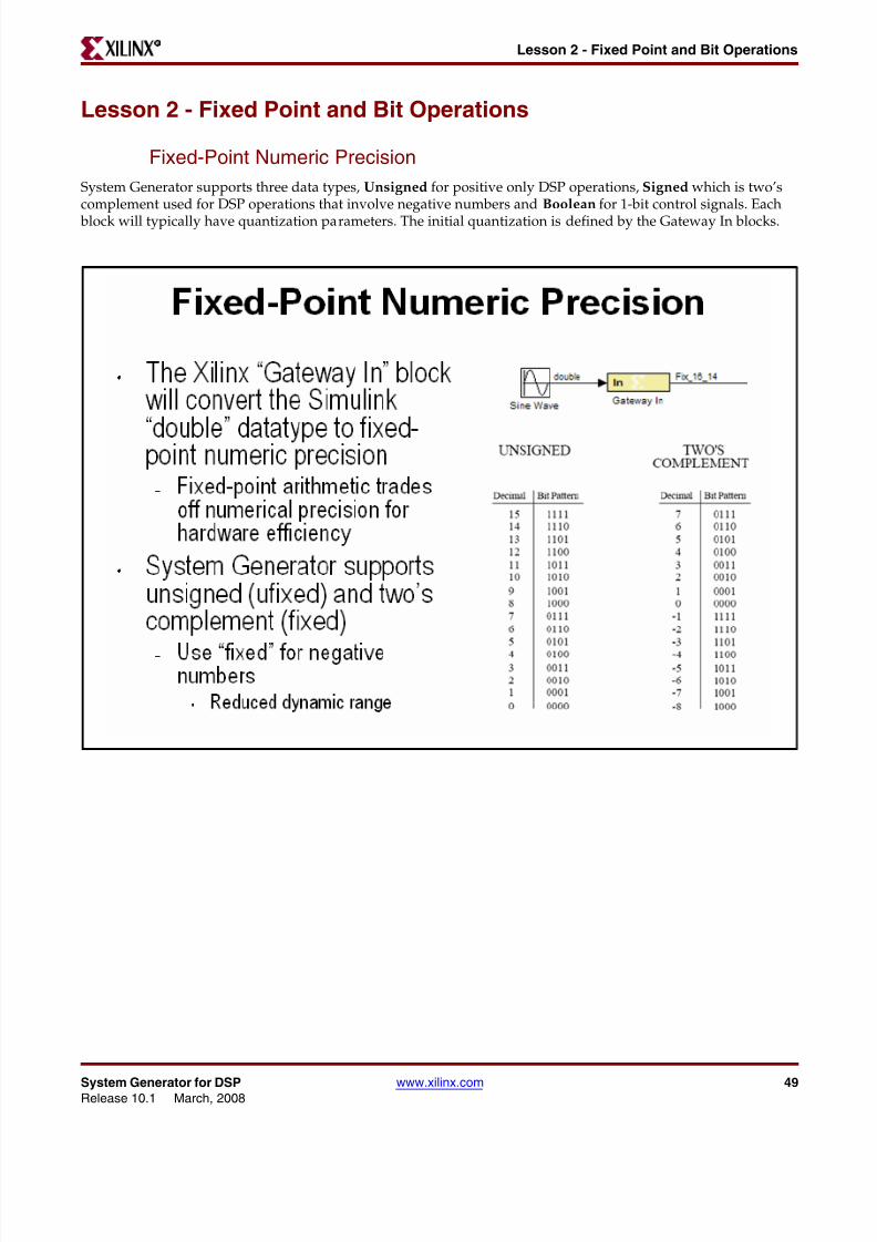
8112019 System Generator for DSP Getting Started
httpslidepdfcomreaderfullsystem-generator-for-dsp-getting-started 5993
System Generator for DSP wwwxilinxcom 59Release 101 March 2008
Lesson 3 - System ControlR
Lesson 3 - System Control
Controlling a DSP System
When you develop a DSP system in hardware some level of control is usually required This may include statedependent behavior or simply performing operations such as filter coefficient updating System-level control may
also be needed for controlling bursty data such as non-streaming FFTs
8112019 System Generator for DSP Getting Started
httpslidepdfcomreaderfullsystem-generator-for-dsp-getting-started 6093
60 wwwxilinxcom System Generator for DSPRelease 101 March 2008
Chapter 4 Getting Started R
The MCode Block
The MCode block supports the use of MATLAB for implementing state dependent and branch conditional controloperations This block is not suitable for MATLAB that describes an algorithmic operation such as a FIR filter orMatrix inverse The Xilinx AccelDSP tool can be used in these cases The MCode block provides a convenient andefficient method for implementing state machines and complex muxing conditions This is the recommended wayto implement a finite state machine in System Generator
8112019 System Generator for DSP Getting Started
httpslidepdfcomreaderfullsystem-generator-for-dsp-getting-started 6193
System Generator for DSP wwwxilinxcom 61Release 101 March 2008
Lesson 3 - System ControlR
The Xilinx ldquoxl_staterdquo Data Type
When implementing a state machine using the MCode block a Xilinx-provided MATLAB function called ldquoxl_staterdquomust be used to initialize a persistent variable This function has two arguments the first is the initial condition thesecond is the quantization of the assigned variable For example if your state machine has 6 states you need aquantization of 4-bits unsigned
8112019 System Generator for DSP Getting Started
httpslidepdfcomreaderfullsystem-generator-for-dsp-getting-started 6293
62 wwwxilinxcom System Generator for DSPRelease 101 March 2008
Chapter 4 Getting Started R
State Machine Example
The figure below shows a simple 2-state FSM This can be easily extended to more states Notice that a variablecalled ldquostaterdquo is declared to be persistent and is initialized to 2 bits unsigned using the ldquoxl_staterdquo function Aswitch-case statement is then used to decode the inputs branch to the next state and assign the outputs
8112019 System Generator for DSP Getting Started
httpslidepdfcomreaderfullsystem-generator-for-dsp-getting-started 6393
System Generator for DSP wwwxilinxcom 63Release 101 March 2008
Lesson 3 - System ControlR
The Expression Block
The Expression block performs a bitwise not and or amp xor on two input signals The inputs can have a word lengthgreater than 1 In cases where the two inputs have different word lengths the binary points are matched up andthen an element-by-element boolean operation is performed This block provides a useful way to implement logicalcontrol in a DSP system
8112019 System Generator for DSP Getting Started
httpslidepdfcomreaderfullsystem-generator-for-dsp-getting-started 6493
64 wwwxilinxcom System Generator for DSPRelease 101 March 2008
Chapter 4 Getting Started R
Reset and Enable Ports
Most System Generator blocks that include memory or storage provide options to expose the reset and clock enableports If un-selected these ports are automatically connected to the final hardwares global reset and clock enable orDCM schemes Exposing these ports on the System Generator block creates a condition where the block is reset orenabled when either the global signals or the local signals assert TRUE You should use these ports if greater controlover these functions is required in the DSP system
8112019 System Generator for DSP Getting Started
httpslidepdfcomreaderfullsystem-generator-for-dsp-getting-started 6593
System Generator for DSP wwwxilinxcom 65Release 101 March 2008
Lesson 3 - System ControlR
Bursty Data
Several of the more complex DSP blocks offered in the Xilinx DSP blockset result in ldquoburstyrdquo data For example thenon-streaming FFT requires several clock cycles to process the input data prior to generating valid output data Inthese cases these blocks include data flow control ports that must be used in the DSP system These ports provide basic push mode dataflow control They consist of a vin port which indicates that valid data is available at theinputs and vout which indicates that valid data is available at the outputs
8112019 System Generator for DSP Getting Started
httpslidepdfcomreaderfullsystem-generator-for-dsp-getting-started 6693
66 wwwxilinxcom System Generator for DSPRelease 101 March 2008
Chapter 4 Getting Started R
Lesson 3 Summary
bull Use the MCode block for state machines and branch conditional logic
bull Use the Expression block to implement logical control at the bit level
bull Storage elements have the ability to include optional reset and clock enable pins thatcan be connected in System Generator
bull Blocks that operate on bursty data include data flow control pins called vin and vout
Lab Exercise System Control
In this lab you will be creating a simple state machine using the MCode block to detect asequence of binary values ldquo1011rdquo The FSM needs to be able to detect multipletransmissions as well ie ldquo10111011rdquo
The lab data and instructions are located in the System Generator software tree at thefollowing pathname
ltsysgen_treegtexamplesgetting_started_traininglab4
Lab InstructionsLab Data
8112019 System Generator for DSP Getting Started
httpslidepdfcomreaderfullsystem-generator-for-dsp-getting-started 6793
System Generator for DSP wwwxilinxcom 67Release 101 March 2008
Lesson 4 - Multi-Rate SystemsR
Lesson 4 - Multi-Rate Systems
Creating Multi-Rate Systems
The following illustration shows a typical base-station receiver The tower has multiple antennas to providesectored coverage of the area The diagram shows that this results in two receiver channels In each of these
channels there is some form of complex mixing resulting in real and imaginary channels
Often DSP systems such as this will down sample the input signals prior to the digital filtering steps performedduring equalization and demodulation Doing so can simplify the filter design and hardware significantly Thesesystems are referred to as ldquomulti-raterdquo systems
8112019 System Generator for DSP Getting Started
httpslidepdfcomreaderfullsystem-generator-for-dsp-getting-started 6893
68 wwwxilinxcom System Generator for DSPRelease 101 March 2008
Chapter 4 Getting Started R
Up and Down Sampling Blocks
System Generator includes Up Sample and Down Sample blocks that change the system sample rate The UpSample block adds additional samples to the signal to achieve the desired rate change The value of these newsamples is either zero or the value of the last actual sample depending on the block options The Down Sample block simply discards samples until it achieves the desired rate change For example downsample by 3 means todiscard 2 out of every 3 samples
8112019 System Generator for DSP Getting Started
httpslidepdfcomreaderfullsystem-generator-for-dsp-getting-started 6993
System Generator for DSP wwwxilinxcom 69Release 101 March 2008
Lesson 4 - Multi-Rate SystemsR
Rate Changing Functional Blocks
In addition to the straightforward ldquoUp Samplerdquo and ldquoDown Samplerdquo blocks System Generator also provides ratechanging functional blocks that is blocks that also perform a specific function The Parallel to Serial block will upsample the Serial to Parallel block will down sample the FIR Compiler if using a resource-shared multiplier willdown sample and the TDM block will up sample
8112019 System Generator for DSP Getting Started
httpslidepdfcomreaderfullsystem-generator-for-dsp-getting-started 7093
70 wwwxilinxcom System Generator for DSPRelease 101 March 2008
Chapter 4 Getting Started R
Viewing Rate Changes in Simulink
Simulink supports viewing different sample times as different colors which is fully supported for System Generator blocks To enable the Sample Time Colors feature select the pulldown menu Format gt Sample Time Colors TheSimulink tool does not automatically recolor the model with each change you make to it so you must select Edit gtUpdate Diagram to explicitly update the model coloration To return to your original coloring disable the sampletime coloration by again choosing Sample Time Colors
8112019 System Generator for DSP Getting Started
httpslidepdfcomreaderfullsystem-generator-for-dsp-getting-started 7193
System Generator for DSP wwwxilinxcom 71Release 101 March 2008
Lesson 4 - Multi-Rate SystemsR
Debugging Tools
System Generator provides 3 debugging utilities to assist in debugging complex multi-rate systems
The Sample Time (ST) probe can be connected to any System Generator signal then to a Simulink ldquodisplayrdquo blockfrom the ldquoSinksrdquo library The sample time for the connected net will appear in the display
The clk probe is not connected to any inputs but only to a scope output It displays the master clock This can beused with the Clock Enable Probe to display the behavior of the clock enable signal at various points in the downsampling
8112019 System Generator for DSP Getting Started
httpslidepdfcomreaderfullsystem-generator-for-dsp-getting-started 7293
72 wwwxilinxcom System Generator for DSPRelease 101 March 2008
Chapter 4 Getting Started R
Sample Period ldquoRulesrdquo
The illustration below is an example of a multi-rate system that demonstrates how the Simulink System Period can be calculated and entered into the System Generator token GUI
If you get it wrong there is a sampling period analyzer that automatically determines the appropriate sampleperiod and prompts you to update the GUI
8112019 System Generator for DSP Getting Started
httpslidepdfcomreaderfullsystem-generator-for-dsp-getting-started 7393
System Generator for DSP wwwxilinxcom 73Release 101 March 2008
Lesson 4 - Multi-Rate SystemsR
Lab Exercise Multi-Rate Systems
In this lab you will be exploring the effects of the rate changing blocks available in SystemGenerator These blocks include Upsample Downsample Serial to Parallel and Parallel toSerial
The lab instructions and lab design are located in the System Generator software tree at the
following pathnameltsysgen_treegtexamplesgetting_started_traininglab5
Lab Instructions
Lab Design
8112019 System Generator for DSP Getting Started
httpslidepdfcomreaderfullsystem-generator-for-dsp-getting-started 7493
74 wwwxilinxcom System Generator for DSPRelease 101 March 2008
Chapter 4 Getting Started R
Lesson 5 - Using Memories
Block vs Distributed RAM
Xilinx FPGAs offer two distinct memory options Block RAM and Distributed RAM Block RAM uses dedicatedon-chip hardware resources and represents the most area-efficient RAM implementation Block RAMs offer high
performance but due to their fixed location on the chip may incur slightly larger routing delays Distributed RAMuses the lookup tables in the FPGA slices to implement memory and in doing so will subtract from the slicesavailable for logical operations Because Distributed RAM can be located anywhere throughout the chip routingdelays can be minimized and slightly higher performance can be achieved Distributed RAM is an excellent optionfor small FIFOs
8112019 System Generator for DSP Getting Started
httpslidepdfcomreaderfullsystem-generator-for-dsp-getting-started 7593
System Generator for DSP wwwxilinxcom 75Release 101 March 2008
Lesson 5 - Using MemoriesR
Initializing RAMs and ROMs
The RAM and ROM blocks can be initialized to a 1xn vector that matches the depth of the RAM MATLAB is usedto set the initial value vector Any MATLAB statement can be used that results in a 1xn vector including the filereading commands such as imread auread wavread and load
8112019 System Generator for DSP Getting Started
httpslidepdfcomreaderfullsystem-generator-for-dsp-getting-started 7693
8112019 System Generator for DSP Getting Started
httpslidepdfcomreaderfullsystem-generator-for-dsp-getting-started 7793
System Generator for DSP wwwxilinxcom 77Release 101 March 2008
Lesson 5 - Using MemoriesR
System Generator ROM Blocks
The ROM block supports an implementation in either Block- or Distributed RAM and is initialized through aMATLAB command The signal connected to the address port must be unsigned with no fractional bits
8112019 System Generator for DSP Getting Started
httpslidepdfcomreaderfullsystem-generator-for-dsp-getting-started 7893
78 wwwxilinxcom System Generator for DSPRelease 101 March 2008
Chapter 4 Getting Started R
The Delay Block
The Delay block is used to synchronize dataflow through the FPGA This block maps to a highly-efficient shiftregister structure built from a slice lookup table called an SRL16 that is 85 smaller than using registers
8112019 System Generator for DSP Getting Started
httpslidepdfcomreaderfullsystem-generator-for-dsp-getting-started 7993
System Generator for DSP wwwxilinxcom 79Release 101 March 2008
Lesson 5 - Using MemoriesR
The FIFO Block
The FIFO block supports both Block RAM and Distributed RAM implementations Depths up to 64K are supportedThree output flags are supported empty full and full The full flag is set depending on a bit widthspecification One bit will be zero until the FIFO is 50 full then it will set to5 Two bits will be zero until 20 fullthen 25 5 and 75
8112019 System Generator for DSP Getting Started
httpslidepdfcomreaderfullsystem-generator-for-dsp-getting-started 8093
80 wwwxilinxcom System Generator for DSPRelease 101 March 2008
Chapter 4 Getting Started R
Lab Exercise Using Memories
In this lab you will learn how to use a Xilinx ROM block to implement a LUT-basedoperation such as an Arcsin using Block RAM or Distributed RAM This provides anefficient implementation for trig and math functions with inputs that can be quantized to10 bits or less
The lab instructions and lab design are located in the System Generator software tree at thefollowing pathname
ltsysgen_treegtexamplesgetting_started_traininglab6
Lab Instructions
Lab Design
8112019 System Generator for DSP Getting Started
httpslidepdfcomreaderfullsystem-generator-for-dsp-getting-started 8193
System Generator for DSP wwwxilinxcom 81Release 101 March 2008
Lesson 6 - Designing FiltersR
Lesson 6 - Designing Filters
Introduction
Digital filters are a common DSP operation and especially well suited to implementation in FPGAs High-performance applications benefit greatly from parallel filters that can return a results on every clock cycle The
Virtex 5 device includes up to 550 parallel multipliers The FIR Compiler is designed to use these multipliers in themost efficient manner for creating commonly used FIR filters An alternative implementation is available calledldquodistributed arithmeticrdquo that creates FIR filters without using multipliers by employing a shift-add technique Thiscan be used for smaller devices when the available multipliers have been allocated to other functions
8112019 System Generator for DSP Getting Started
httpslidepdfcomreaderfullsystem-generator-for-dsp-getting-started 8293
82 wwwxilinxcom System Generator for DSPRelease 101 March 2008
Chapter 4 Getting Started R
The Virtex DSP48 Math Slice
The Virtextrade family introduces a high-performance arithmetic unit along with a multiplier the low-power DSP48slice The following figure is a detailed diagram of the DSP48 structure The DSP48 slice consists of four mainsections (1) IO registers (2) signed multiplier (3) three-input addersubtractor and (4) OPMODE multiplexers
8112019 System Generator for DSP Getting Started
httpslidepdfcomreaderfullsystem-generator-for-dsp-getting-started 8393
System Generator for DSP wwwxilinxcom 83Release 101 March 2008
Lesson 6 - Designing FiltersR
FIR Compiler Block
The Xilinx Fir Compiler v1_0 block implements a high speed MAC based FIR filter It accepts a stream of input dataand computes filtered output with a fixed delay based on the filter configuration The FIR Compiler supportsgeneration of resource shared or parallel FIR structures and polyphase decimation and interpolation structuresAlso supported is oversampling Coefficients are specified using MATLAB commands
8112019 System Generator for DSP Getting Started
httpslidepdfcomreaderfullsystem-generator-for-dsp-getting-started 8493
84 wwwxilinxcom System Generator for DSPRelease 101 March 2008
Chapter 4 Getting Started R
Creating Coefficients with FDATool
The Mathworks FDATool is a graphical filter design program that can be used to generate coefficients for the FIRCompiler block
8112019 System Generator for DSP Getting Started
httpslidepdfcomreaderfullsystem-generator-for-dsp-getting-started 8593
System Generator for DSP wwwxilinxcom 85Release 101 March 2008
Lesson 6 - Designing FiltersR
Using FDA Tool Coefficients
Once a suitable filter response has been designed you simply export the coefficients to the workspace using theFile gt Export command The workspace variable can then be referenced in the FIR Compiler properties editor
8112019 System Generator for DSP Getting Started
httpslidepdfcomreaderfullsystem-generator-for-dsp-getting-started 8693
86 wwwxilinxcom System Generator for DSPRelease 101 March 2008
Chapter 4 Getting Started R
Lab Exercise Designing Filters
In this lab you will be using the Filter Compiler block to generate optimized filters for theVirtex4 architecture
The lab instructions and lab design are located in the System Generator software tree at thefollowing pathname
ltsysgen_treegtexamplesgetting_started_traininglab7
Lab Instructions
Lab Design
8112019 System Generator for DSP Getting Started
httpslidepdfcomreaderfullsystem-generator-for-dsp-getting-started 8793
System Generator for DSP wwwxilinxcom 87Release 101 March 2008
Additional Examples and TutorialsR
Additional Examples and Tutorials
Numerous examples are used to illustrate System Generator features and functions in theSystem Generator documentaton These examples are found in the directory at pathnameltsysgen_treegtexamples and are listed in the table below In addition to theseexamples System Generator also includes demonstration models that can be run from the
demo page Enter the following command at the MATLAB promptdemo blocksets xilinx
Note If you are using the MATLAB help browser you can open and run the examples directly fromthis page To run an example click on the link MATLAB will change directories to the exampledirectory and open the example model
Black Box Examples
ChipScope Examples
Topic Description
Importing a VHDL
Module
A tutorial showing how to use the black box to import VHDL into a
System Generator design and how to use ModelSim to co-simulatethe VHDL module
Simulating SeveralBlack BoxesSimultaneously
Shows how black boxes can co-simulate simultaneously using onlyone ModelSim license
Dynamic Black Boxes A tutorial showing how to parameterize the black box
Importing a VerilogModule
A tutorial showing how to use the black box to import Verilog intoa System Generator design and how to use ModelSim to co-simulatethe Verilog module
Importing a Xilinx
Core GeneratorModule
A tutorial showing how to import a COREGEN module as a black
box
Topic Description
Using ChipScope ProAnalyzer for Real-Time HardwareDebugging
This tutorial demonstrates how to connect and use the Xilinx DebugTool called ChipScope Pro within Xilinx System Generator Theintegration of ChipScope Pro in the System Generator flow allowsreal-time debugging at system speed
8112019 System Generator for DSP Getting Started
httpslidepdfcomreaderfullsystem-generator-for-dsp-getting-started 8893
88 wwwxilinxcom System Generator for DSPRelease 101 March 2008
Chapter 4 Getting Started R
DSP Examples
Topic Description
DSP48 Block Simple example demonstrating the use of the DSP48 block with the
Constant block used to provide the DSP48 instruction
DSP48 Macro Block Simple example demonstrating how to use a DSP48 Macro block toimplement a Complex Multiplier
DSP48 Block
(35-Bit Multiplierusing DSP48 andConstant block)
This design demonstrates the use of the DSP48 and Constant blockin implementing 35 by 35-bit multipliers at different sample ratesThree multipliers implementations are shown at 1 2 and 4 clocksper sample
DSP48 Macro Block
(FIR filter using theDSP48 Macro block as
a multiply accumulatefunction)
This design demonstrates the use of the DSP48 Macro block inimplementing a 35 by 35 Multiplier
DSP48 Block
FIR filter examplesusing DSP48 block
This design demonstrates the use of the DSP48 and Constant blockin FIR filter implementation The design includes sets of parallelsemi-parallel and sequential FIR filter using Type 1 and Type 2architectures Each filter implements a 16-tap dsp48-based FIRfilters
DSP48 DesignTechniques
(DSP48-baseddynamic shifter)
This design demonstrates the use of the DSP48 block inimplementing a 35-bit signed right shift using 2 DSP48s
DSP48 DesignTechniques
(Synthesizable FIRfilter for Virtex4)
This design demonstrates how to use System Generator toimplement a synthesizable FIR filter which maps efficiently to theVirtex4 architecture
DSP48 Macro Block
(FIR filter using theDSP48 Macro block asa multiply accumulatefunction)
This design demonstrates the use of the DSP48 Macro block whenimplementing a sequential FIR filter
MAC FIR filter This design example implements a 43 tap FIR Filter with a MACengine and a Dual Port Ram used for data and coefficient storage
Complex FIR filter This example demonstrates a complex FIR filter built out of blocksfrom the System Generator and Simulink library
8112019 System Generator for DSP Getting Started
httpslidepdfcomreaderfullsystem-generator-for-dsp-getting-started 8993
System Generator for DSP wwwxilinxcom 89Release 101 March 2008
Additional Examples and TutorialsR
M-Code Examples
Processor Examples
Topic Description
Simple Selector This example shows how to implement a function that returns the
maximum value of its inputsSimple ArithmeticOperations
This example shows how to implement simple arithmeticoperations
Complex Multiplierwith Latency
This example shows how to build a complex multiplier with latency
Shift Operations This example shows how to implement shift operations
Passing Parametersinto the MCode Block
This example shows how to pass parameters into a MCode block
Optional Input Ports This example shows how to implement optional input ports on an
MCode blockFinite State Machines This example shows how to implement a finite state machine
ParameterizableAccumulator
This example shows how to build a parameterizable accumulator
FIR Blocks andVerification
This example shows how to model FIR blocks and how to do systemverification
RPN Calculator This example shows how to model a RPN calculator ndash a stackmachine
Example of disp
function
This example shows how to use the disp function
Topic Description
Designing andExporting MicroBlazeProcessor Peripherals
Demonstrates how to export a design from System Generator intoXilinx Platform Studio (EDK) by showing how to design aperipheral (pcore) for a MicroBlaze processor An RGB to gray-scalecolor space converter is created and generated into a pcore using theExport to EDK compilation target
8112019 System Generator for DSP Getting Started
httpslidepdfcomreaderfullsystem-generator-for-dsp-getting-started 9093
90 wwwxilinxcom System Generator for DSPRelease 101 March 2008
Chapter 4 Getting Started R
Shared Memory Examples
Tutorial Example -Designing andSimulatingMicroBlaze ProcessorSystems
Demonstrates how to import a MicroBlaze processor created usingXilinx Platform Studio into System Generator A DSP48 block isused as a co-processor to the MicroBlaze
Designing PicoBlazeMicrocontrollerApplications
Demonstrates how to implement a PicoBlaze program in SystemGenerator The example programs the PicoBlaze to alter the outputfrequency of a Direct Digital Synthesizer (DDS) during an interrupt
Topic Description
Topic Description
Simulation across
various models
Illustrates shared memories communicating across Simulink
models
Host PC SharedMemory access
Developer studio project to communicate with a shared memory
High Speed VideoProcessing usingHardware Co-simulation
Discussion of a high-speed co-simulation buffering interfacefollowed by an example in which the interface is used to supportreal-time processing of a video stream using a 5x5 filter kernel
High speed IOBuffering
Illustrates high speed Shared Memory IO Buffering Interface forHardware Co-simulation
SharedMemory
(Mex-functioninterface)
Illustrates the use of a mex-function as an interface to a sharedmemory
Generating MultipleCycle-True Islands forDistinct Clocks
An example using two asynchronous clocks
Shared Memory ToFIFO To Register ToRegister FromRegister
Demonstrates use of shared memories FIFOs and registers to passinformation
Frame-BasedAcceleration usingHardware Co-
Simulation
Explains how to use frame or vector-based transfers to furtheraccelerate simulations using FPGA hardware co-simulation
8112019 System Generator for DSP Getting Started
httpslidepdfcomreaderfullsystem-generator-for-dsp-getting-started 9193
System Generator for DSP wwwxilinxcom 91Release 101 March 2008
Additional Examples and TutorialsR
Timing Analysis Examples
Miscellaneous Examples
Topic Description
Timing Analysis
Tutorial
Explains how to use the System Generator Timing Analysis tool to
meet timing requirements of System Generator designs Alsotouches on techniques that may be used when a design does notmeet timing
Topic Description
Importing a SystemGenerator Design intoa Bigger System
Discusses how to take the VHDL netlist from a System Generatordesign and synthesize it in order to embed it into a larger designAlso shows how VHDL created by System Generator can beincorporated into simulation model of the overall system
ConfigurableSubsystems andSystem Generator
Illustrates the use of Configurable Subsystems for Simulation andGeneration
Integrator This example uses an integrator to illustrate error analysiscapability
Block RAM-BasedState Machines
Demonstrates use of Mealy State Machine block from the referencelibrary
8112019 System Generator for DSP Getting Started
httpslidepdfcomreaderfullsystem-generator-for-dsp-getting-started 9293
92 wwwxilinxcom System Generator for DSPRelease 101 March 2008
Chapter 4 Getting Started R
System Generator Demos
System Generator for DSP provides the capability to model and implement high-performance DSP systems in field- programmable gate arrays (FPGAs) using SimulinkThe Xilinx Blockset contains bit and cycle-true models of arithmetic and logic functionsmemories and DSP functions for digital filtering spectral analysis and digitalcommunications System Generator converts a Simulink model of Xilinx blocks into anefficient hardware implementation that combines synthesizable VHDL and intellectualproperty blocks that have been hand-crafted to run efficiently in FPGAs
Included with the tool are numerous demonstration designs that highlight key featuresand tool capabilities as well as general good design practices using real-world designapplications These designs may be accessed from the System Generator demo page Enterthe following command at the MATLAB prompt
demo blocksets xilinx
8112019 System Generator for DSP Getting Started
httpslidepdfcomreaderfullsystem-generator-for-dsp-getting-started 9393
AAsynchronous Software Drivers
for FSLs 25
CCompatibility
MATLAB 24 29 34 36
ModelSim 24 29 34 36
Synplify Pro 24 29 34 36
Compiling
Xilinx HDL Libraries 21
Configuring
the Sysgen cache 21
Custom Bus Interfacesfor exported pcore 26
DDownloading
System Generator 19
EExport pcore
enable Custom Bus Interfaces 26
FFast Simplex Link
asynchronous software drivers for 25
H
MMATLAB 24 29 34 36
Memory Stitching 31ModelSim 24 29 34 36
PPcore
export as under development 26
SShared Memory Stitching 31
Software Drivers
asynchronous for FSLs 25System Generator
Cache 21
changing versions 21
displaying versions 21
downloading the software 19
ISE Design Suite Installer 20
System Generator Utilities
xlUpdateModel 37
U
Underdevelopmentexport pcore as 26
XXilinx HDL Libraries
compiling 21
xlUpdateModel 37
Index
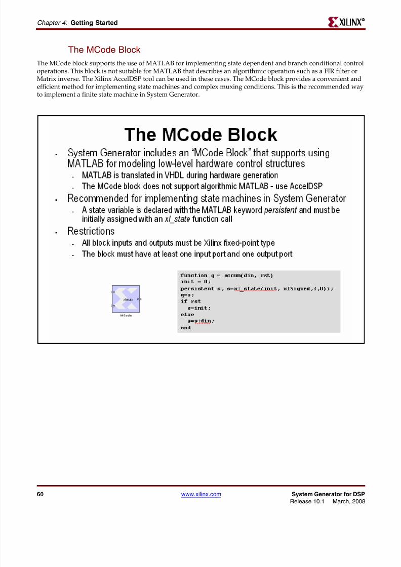
8112019 System Generator for DSP Getting Started
httpslidepdfcomreaderfullsystem-generator-for-dsp-getting-started 6393
System Generator for DSP wwwxilinxcom 63Release 101 March 2008
Lesson 3 - System ControlR
The Expression Block
The Expression block performs a bitwise not and or amp xor on two input signals The inputs can have a word lengthgreater than 1 In cases where the two inputs have different word lengths the binary points are matched up andthen an element-by-element boolean operation is performed This block provides a useful way to implement logicalcontrol in a DSP system
8112019 System Generator for DSP Getting Started
httpslidepdfcomreaderfullsystem-generator-for-dsp-getting-started 6493
64 wwwxilinxcom System Generator for DSPRelease 101 March 2008
Chapter 4 Getting Started R
Reset and Enable Ports
Most System Generator blocks that include memory or storage provide options to expose the reset and clock enableports If un-selected these ports are automatically connected to the final hardwares global reset and clock enable orDCM schemes Exposing these ports on the System Generator block creates a condition where the block is reset orenabled when either the global signals or the local signals assert TRUE You should use these ports if greater controlover these functions is required in the DSP system
8112019 System Generator for DSP Getting Started
httpslidepdfcomreaderfullsystem-generator-for-dsp-getting-started 6593
System Generator for DSP wwwxilinxcom 65Release 101 March 2008
Lesson 3 - System ControlR
Bursty Data
Several of the more complex DSP blocks offered in the Xilinx DSP blockset result in ldquoburstyrdquo data For example thenon-streaming FFT requires several clock cycles to process the input data prior to generating valid output data Inthese cases these blocks include data flow control ports that must be used in the DSP system These ports provide basic push mode dataflow control They consist of a vin port which indicates that valid data is available at theinputs and vout which indicates that valid data is available at the outputs
8112019 System Generator for DSP Getting Started
httpslidepdfcomreaderfullsystem-generator-for-dsp-getting-started 6693
66 wwwxilinxcom System Generator for DSPRelease 101 March 2008
Chapter 4 Getting Started R
Lesson 3 Summary
bull Use the MCode block for state machines and branch conditional logic
bull Use the Expression block to implement logical control at the bit level
bull Storage elements have the ability to include optional reset and clock enable pins thatcan be connected in System Generator
bull Blocks that operate on bursty data include data flow control pins called vin and vout
Lab Exercise System Control
In this lab you will be creating a simple state machine using the MCode block to detect asequence of binary values ldquo1011rdquo The FSM needs to be able to detect multipletransmissions as well ie ldquo10111011rdquo
The lab data and instructions are located in the System Generator software tree at thefollowing pathname
ltsysgen_treegtexamplesgetting_started_traininglab4
Lab InstructionsLab Data
8112019 System Generator for DSP Getting Started
httpslidepdfcomreaderfullsystem-generator-for-dsp-getting-started 6793
System Generator for DSP wwwxilinxcom 67Release 101 March 2008
Lesson 4 - Multi-Rate SystemsR
Lesson 4 - Multi-Rate Systems
Creating Multi-Rate Systems
The following illustration shows a typical base-station receiver The tower has multiple antennas to providesectored coverage of the area The diagram shows that this results in two receiver channels In each of these
channels there is some form of complex mixing resulting in real and imaginary channels
Often DSP systems such as this will down sample the input signals prior to the digital filtering steps performedduring equalization and demodulation Doing so can simplify the filter design and hardware significantly Thesesystems are referred to as ldquomulti-raterdquo systems
8112019 System Generator for DSP Getting Started
httpslidepdfcomreaderfullsystem-generator-for-dsp-getting-started 6893
68 wwwxilinxcom System Generator for DSPRelease 101 March 2008
Chapter 4 Getting Started R
Up and Down Sampling Blocks
System Generator includes Up Sample and Down Sample blocks that change the system sample rate The UpSample block adds additional samples to the signal to achieve the desired rate change The value of these newsamples is either zero or the value of the last actual sample depending on the block options The Down Sample block simply discards samples until it achieves the desired rate change For example downsample by 3 means todiscard 2 out of every 3 samples
8112019 System Generator for DSP Getting Started
httpslidepdfcomreaderfullsystem-generator-for-dsp-getting-started 6993
System Generator for DSP wwwxilinxcom 69Release 101 March 2008
Lesson 4 - Multi-Rate SystemsR
Rate Changing Functional Blocks
In addition to the straightforward ldquoUp Samplerdquo and ldquoDown Samplerdquo blocks System Generator also provides ratechanging functional blocks that is blocks that also perform a specific function The Parallel to Serial block will upsample the Serial to Parallel block will down sample the FIR Compiler if using a resource-shared multiplier willdown sample and the TDM block will up sample
8112019 System Generator for DSP Getting Started
httpslidepdfcomreaderfullsystem-generator-for-dsp-getting-started 7093
70 wwwxilinxcom System Generator for DSPRelease 101 March 2008
Chapter 4 Getting Started R
Viewing Rate Changes in Simulink
Simulink supports viewing different sample times as different colors which is fully supported for System Generator blocks To enable the Sample Time Colors feature select the pulldown menu Format gt Sample Time Colors TheSimulink tool does not automatically recolor the model with each change you make to it so you must select Edit gtUpdate Diagram to explicitly update the model coloration To return to your original coloring disable the sampletime coloration by again choosing Sample Time Colors
8112019 System Generator for DSP Getting Started
httpslidepdfcomreaderfullsystem-generator-for-dsp-getting-started 7193
System Generator for DSP wwwxilinxcom 71Release 101 March 2008
Lesson 4 - Multi-Rate SystemsR
Debugging Tools
System Generator provides 3 debugging utilities to assist in debugging complex multi-rate systems
The Sample Time (ST) probe can be connected to any System Generator signal then to a Simulink ldquodisplayrdquo blockfrom the ldquoSinksrdquo library The sample time for the connected net will appear in the display
The clk probe is not connected to any inputs but only to a scope output It displays the master clock This can beused with the Clock Enable Probe to display the behavior of the clock enable signal at various points in the downsampling
8112019 System Generator for DSP Getting Started
httpslidepdfcomreaderfullsystem-generator-for-dsp-getting-started 7293
72 wwwxilinxcom System Generator for DSPRelease 101 March 2008
Chapter 4 Getting Started R
Sample Period ldquoRulesrdquo
The illustration below is an example of a multi-rate system that demonstrates how the Simulink System Period can be calculated and entered into the System Generator token GUI
If you get it wrong there is a sampling period analyzer that automatically determines the appropriate sampleperiod and prompts you to update the GUI
8112019 System Generator for DSP Getting Started
httpslidepdfcomreaderfullsystem-generator-for-dsp-getting-started 7393
System Generator for DSP wwwxilinxcom 73Release 101 March 2008
Lesson 4 - Multi-Rate SystemsR
Lab Exercise Multi-Rate Systems
In this lab you will be exploring the effects of the rate changing blocks available in SystemGenerator These blocks include Upsample Downsample Serial to Parallel and Parallel toSerial
The lab instructions and lab design are located in the System Generator software tree at the
following pathnameltsysgen_treegtexamplesgetting_started_traininglab5
Lab Instructions
Lab Design
8112019 System Generator for DSP Getting Started
httpslidepdfcomreaderfullsystem-generator-for-dsp-getting-started 7493
74 wwwxilinxcom System Generator for DSPRelease 101 March 2008
Chapter 4 Getting Started R
Lesson 5 - Using Memories
Block vs Distributed RAM
Xilinx FPGAs offer two distinct memory options Block RAM and Distributed RAM Block RAM uses dedicatedon-chip hardware resources and represents the most area-efficient RAM implementation Block RAMs offer high
performance but due to their fixed location on the chip may incur slightly larger routing delays Distributed RAMuses the lookup tables in the FPGA slices to implement memory and in doing so will subtract from the slicesavailable for logical operations Because Distributed RAM can be located anywhere throughout the chip routingdelays can be minimized and slightly higher performance can be achieved Distributed RAM is an excellent optionfor small FIFOs
8112019 System Generator for DSP Getting Started
httpslidepdfcomreaderfullsystem-generator-for-dsp-getting-started 7593
System Generator for DSP wwwxilinxcom 75Release 101 March 2008
Lesson 5 - Using MemoriesR
Initializing RAMs and ROMs
The RAM and ROM blocks can be initialized to a 1xn vector that matches the depth of the RAM MATLAB is usedto set the initial value vector Any MATLAB statement can be used that results in a 1xn vector including the filereading commands such as imread auread wavread and load
8112019 System Generator for DSP Getting Started
httpslidepdfcomreaderfullsystem-generator-for-dsp-getting-started 7693
8112019 System Generator for DSP Getting Started
httpslidepdfcomreaderfullsystem-generator-for-dsp-getting-started 7793
System Generator for DSP wwwxilinxcom 77Release 101 March 2008
Lesson 5 - Using MemoriesR
System Generator ROM Blocks
The ROM block supports an implementation in either Block- or Distributed RAM and is initialized through aMATLAB command The signal connected to the address port must be unsigned with no fractional bits
8112019 System Generator for DSP Getting Started
httpslidepdfcomreaderfullsystem-generator-for-dsp-getting-started 7893
78 wwwxilinxcom System Generator for DSPRelease 101 March 2008
Chapter 4 Getting Started R
The Delay Block
The Delay block is used to synchronize dataflow through the FPGA This block maps to a highly-efficient shiftregister structure built from a slice lookup table called an SRL16 that is 85 smaller than using registers
8112019 System Generator for DSP Getting Started
httpslidepdfcomreaderfullsystem-generator-for-dsp-getting-started 7993
System Generator for DSP wwwxilinxcom 79Release 101 March 2008
Lesson 5 - Using MemoriesR
The FIFO Block
The FIFO block supports both Block RAM and Distributed RAM implementations Depths up to 64K are supportedThree output flags are supported empty full and full The full flag is set depending on a bit widthspecification One bit will be zero until the FIFO is 50 full then it will set to5 Two bits will be zero until 20 fullthen 25 5 and 75
8112019 System Generator for DSP Getting Started
httpslidepdfcomreaderfullsystem-generator-for-dsp-getting-started 8093
80 wwwxilinxcom System Generator for DSPRelease 101 March 2008
Chapter 4 Getting Started R
Lab Exercise Using Memories
In this lab you will learn how to use a Xilinx ROM block to implement a LUT-basedoperation such as an Arcsin using Block RAM or Distributed RAM This provides anefficient implementation for trig and math functions with inputs that can be quantized to10 bits or less
The lab instructions and lab design are located in the System Generator software tree at thefollowing pathname
ltsysgen_treegtexamplesgetting_started_traininglab6
Lab Instructions
Lab Design
8112019 System Generator for DSP Getting Started
httpslidepdfcomreaderfullsystem-generator-for-dsp-getting-started 8193
System Generator for DSP wwwxilinxcom 81Release 101 March 2008
Lesson 6 - Designing FiltersR
Lesson 6 - Designing Filters
Introduction
Digital filters are a common DSP operation and especially well suited to implementation in FPGAs High-performance applications benefit greatly from parallel filters that can return a results on every clock cycle The
Virtex 5 device includes up to 550 parallel multipliers The FIR Compiler is designed to use these multipliers in themost efficient manner for creating commonly used FIR filters An alternative implementation is available calledldquodistributed arithmeticrdquo that creates FIR filters without using multipliers by employing a shift-add technique Thiscan be used for smaller devices when the available multipliers have been allocated to other functions
8112019 System Generator for DSP Getting Started
httpslidepdfcomreaderfullsystem-generator-for-dsp-getting-started 8293
82 wwwxilinxcom System Generator for DSPRelease 101 March 2008
Chapter 4 Getting Started R
The Virtex DSP48 Math Slice
The Virtextrade family introduces a high-performance arithmetic unit along with a multiplier the low-power DSP48slice The following figure is a detailed diagram of the DSP48 structure The DSP48 slice consists of four mainsections (1) IO registers (2) signed multiplier (3) three-input addersubtractor and (4) OPMODE multiplexers
8112019 System Generator for DSP Getting Started
httpslidepdfcomreaderfullsystem-generator-for-dsp-getting-started 8393
System Generator for DSP wwwxilinxcom 83Release 101 March 2008
Lesson 6 - Designing FiltersR
FIR Compiler Block
The Xilinx Fir Compiler v1_0 block implements a high speed MAC based FIR filter It accepts a stream of input dataand computes filtered output with a fixed delay based on the filter configuration The FIR Compiler supportsgeneration of resource shared or parallel FIR structures and polyphase decimation and interpolation structuresAlso supported is oversampling Coefficients are specified using MATLAB commands
8112019 System Generator for DSP Getting Started
httpslidepdfcomreaderfullsystem-generator-for-dsp-getting-started 8493
84 wwwxilinxcom System Generator for DSPRelease 101 March 2008
Chapter 4 Getting Started R
Creating Coefficients with FDATool
The Mathworks FDATool is a graphical filter design program that can be used to generate coefficients for the FIRCompiler block
8112019 System Generator for DSP Getting Started
httpslidepdfcomreaderfullsystem-generator-for-dsp-getting-started 8593
System Generator for DSP wwwxilinxcom 85Release 101 March 2008
Lesson 6 - Designing FiltersR
Using FDA Tool Coefficients
Once a suitable filter response has been designed you simply export the coefficients to the workspace using theFile gt Export command The workspace variable can then be referenced in the FIR Compiler properties editor
8112019 System Generator for DSP Getting Started
httpslidepdfcomreaderfullsystem-generator-for-dsp-getting-started 8693
86 wwwxilinxcom System Generator for DSPRelease 101 March 2008
Chapter 4 Getting Started R
Lab Exercise Designing Filters
In this lab you will be using the Filter Compiler block to generate optimized filters for theVirtex4 architecture
The lab instructions and lab design are located in the System Generator software tree at thefollowing pathname
ltsysgen_treegtexamplesgetting_started_traininglab7
Lab Instructions
Lab Design
8112019 System Generator for DSP Getting Started
httpslidepdfcomreaderfullsystem-generator-for-dsp-getting-started 8793
System Generator for DSP wwwxilinxcom 87Release 101 March 2008
Additional Examples and TutorialsR
Additional Examples and Tutorials
Numerous examples are used to illustrate System Generator features and functions in theSystem Generator documentaton These examples are found in the directory at pathnameltsysgen_treegtexamples and are listed in the table below In addition to theseexamples System Generator also includes demonstration models that can be run from the
demo page Enter the following command at the MATLAB promptdemo blocksets xilinx
Note If you are using the MATLAB help browser you can open and run the examples directly fromthis page To run an example click on the link MATLAB will change directories to the exampledirectory and open the example model
Black Box Examples
ChipScope Examples
Topic Description
Importing a VHDL
Module
A tutorial showing how to use the black box to import VHDL into a
System Generator design and how to use ModelSim to co-simulatethe VHDL module
Simulating SeveralBlack BoxesSimultaneously
Shows how black boxes can co-simulate simultaneously using onlyone ModelSim license
Dynamic Black Boxes A tutorial showing how to parameterize the black box
Importing a VerilogModule
A tutorial showing how to use the black box to import Verilog intoa System Generator design and how to use ModelSim to co-simulatethe Verilog module
Importing a Xilinx
Core GeneratorModule
A tutorial showing how to import a COREGEN module as a black
box
Topic Description
Using ChipScope ProAnalyzer for Real-Time HardwareDebugging
This tutorial demonstrates how to connect and use the Xilinx DebugTool called ChipScope Pro within Xilinx System Generator Theintegration of ChipScope Pro in the System Generator flow allowsreal-time debugging at system speed
8112019 System Generator for DSP Getting Started
httpslidepdfcomreaderfullsystem-generator-for-dsp-getting-started 8893
88 wwwxilinxcom System Generator for DSPRelease 101 March 2008
Chapter 4 Getting Started R
DSP Examples
Topic Description
DSP48 Block Simple example demonstrating the use of the DSP48 block with the
Constant block used to provide the DSP48 instruction
DSP48 Macro Block Simple example demonstrating how to use a DSP48 Macro block toimplement a Complex Multiplier
DSP48 Block
(35-Bit Multiplierusing DSP48 andConstant block)
This design demonstrates the use of the DSP48 and Constant blockin implementing 35 by 35-bit multipliers at different sample ratesThree multipliers implementations are shown at 1 2 and 4 clocksper sample
DSP48 Macro Block
(FIR filter using theDSP48 Macro block as
a multiply accumulatefunction)
This design demonstrates the use of the DSP48 Macro block inimplementing a 35 by 35 Multiplier
DSP48 Block
FIR filter examplesusing DSP48 block
This design demonstrates the use of the DSP48 and Constant blockin FIR filter implementation The design includes sets of parallelsemi-parallel and sequential FIR filter using Type 1 and Type 2architectures Each filter implements a 16-tap dsp48-based FIRfilters
DSP48 DesignTechniques
(DSP48-baseddynamic shifter)
This design demonstrates the use of the DSP48 block inimplementing a 35-bit signed right shift using 2 DSP48s
DSP48 DesignTechniques
(Synthesizable FIRfilter for Virtex4)
This design demonstrates how to use System Generator toimplement a synthesizable FIR filter which maps efficiently to theVirtex4 architecture
DSP48 Macro Block
(FIR filter using theDSP48 Macro block asa multiply accumulatefunction)
This design demonstrates the use of the DSP48 Macro block whenimplementing a sequential FIR filter
MAC FIR filter This design example implements a 43 tap FIR Filter with a MACengine and a Dual Port Ram used for data and coefficient storage
Complex FIR filter This example demonstrates a complex FIR filter built out of blocksfrom the System Generator and Simulink library
8112019 System Generator for DSP Getting Started
httpslidepdfcomreaderfullsystem-generator-for-dsp-getting-started 8993
System Generator for DSP wwwxilinxcom 89Release 101 March 2008
Additional Examples and TutorialsR
M-Code Examples
Processor Examples
Topic Description
Simple Selector This example shows how to implement a function that returns the
maximum value of its inputsSimple ArithmeticOperations
This example shows how to implement simple arithmeticoperations
Complex Multiplierwith Latency
This example shows how to build a complex multiplier with latency
Shift Operations This example shows how to implement shift operations
Passing Parametersinto the MCode Block
This example shows how to pass parameters into a MCode block
Optional Input Ports This example shows how to implement optional input ports on an
MCode blockFinite State Machines This example shows how to implement a finite state machine
ParameterizableAccumulator
This example shows how to build a parameterizable accumulator
FIR Blocks andVerification
This example shows how to model FIR blocks and how to do systemverification
RPN Calculator This example shows how to model a RPN calculator ndash a stackmachine
Example of disp
function
This example shows how to use the disp function
Topic Description
Designing andExporting MicroBlazeProcessor Peripherals
Demonstrates how to export a design from System Generator intoXilinx Platform Studio (EDK) by showing how to design aperipheral (pcore) for a MicroBlaze processor An RGB to gray-scalecolor space converter is created and generated into a pcore using theExport to EDK compilation target
8112019 System Generator for DSP Getting Started
httpslidepdfcomreaderfullsystem-generator-for-dsp-getting-started 9093
90 wwwxilinxcom System Generator for DSPRelease 101 March 2008
Chapter 4 Getting Started R
Shared Memory Examples
Tutorial Example -Designing andSimulatingMicroBlaze ProcessorSystems
Demonstrates how to import a MicroBlaze processor created usingXilinx Platform Studio into System Generator A DSP48 block isused as a co-processor to the MicroBlaze
Designing PicoBlazeMicrocontrollerApplications
Demonstrates how to implement a PicoBlaze program in SystemGenerator The example programs the PicoBlaze to alter the outputfrequency of a Direct Digital Synthesizer (DDS) during an interrupt
Topic Description
Topic Description
Simulation across
various models
Illustrates shared memories communicating across Simulink
models
Host PC SharedMemory access
Developer studio project to communicate with a shared memory
High Speed VideoProcessing usingHardware Co-simulation
Discussion of a high-speed co-simulation buffering interfacefollowed by an example in which the interface is used to supportreal-time processing of a video stream using a 5x5 filter kernel
High speed IOBuffering
Illustrates high speed Shared Memory IO Buffering Interface forHardware Co-simulation
SharedMemory
(Mex-functioninterface)
Illustrates the use of a mex-function as an interface to a sharedmemory
Generating MultipleCycle-True Islands forDistinct Clocks
An example using two asynchronous clocks
Shared Memory ToFIFO To Register ToRegister FromRegister
Demonstrates use of shared memories FIFOs and registers to passinformation
Frame-BasedAcceleration usingHardware Co-
Simulation
Explains how to use frame or vector-based transfers to furtheraccelerate simulations using FPGA hardware co-simulation
8112019 System Generator for DSP Getting Started
httpslidepdfcomreaderfullsystem-generator-for-dsp-getting-started 9193
System Generator for DSP wwwxilinxcom 91Release 101 March 2008
Additional Examples and TutorialsR
Timing Analysis Examples
Miscellaneous Examples
Topic Description
Timing Analysis
Tutorial
Explains how to use the System Generator Timing Analysis tool to
meet timing requirements of System Generator designs Alsotouches on techniques that may be used when a design does notmeet timing
Topic Description
Importing a SystemGenerator Design intoa Bigger System
Discusses how to take the VHDL netlist from a System Generatordesign and synthesize it in order to embed it into a larger designAlso shows how VHDL created by System Generator can beincorporated into simulation model of the overall system
ConfigurableSubsystems andSystem Generator
Illustrates the use of Configurable Subsystems for Simulation andGeneration
Integrator This example uses an integrator to illustrate error analysiscapability
Block RAM-BasedState Machines
Demonstrates use of Mealy State Machine block from the referencelibrary
8112019 System Generator for DSP Getting Started
httpslidepdfcomreaderfullsystem-generator-for-dsp-getting-started 9293
92 wwwxilinxcom System Generator for DSPRelease 101 March 2008
Chapter 4 Getting Started R
System Generator Demos
System Generator for DSP provides the capability to model and implement high-performance DSP systems in field- programmable gate arrays (FPGAs) using SimulinkThe Xilinx Blockset contains bit and cycle-true models of arithmetic and logic functionsmemories and DSP functions for digital filtering spectral analysis and digitalcommunications System Generator converts a Simulink model of Xilinx blocks into anefficient hardware implementation that combines synthesizable VHDL and intellectualproperty blocks that have been hand-crafted to run efficiently in FPGAs
Included with the tool are numerous demonstration designs that highlight key featuresand tool capabilities as well as general good design practices using real-world designapplications These designs may be accessed from the System Generator demo page Enterthe following command at the MATLAB prompt
demo blocksets xilinx
8112019 System Generator for DSP Getting Started
httpslidepdfcomreaderfullsystem-generator-for-dsp-getting-started 9393
AAsynchronous Software Drivers
for FSLs 25
CCompatibility
MATLAB 24 29 34 36
ModelSim 24 29 34 36
Synplify Pro 24 29 34 36
Compiling
Xilinx HDL Libraries 21
Configuring
the Sysgen cache 21
Custom Bus Interfacesfor exported pcore 26
DDownloading
System Generator 19
EExport pcore
enable Custom Bus Interfaces 26
FFast Simplex Link
asynchronous software drivers for 25
H
MMATLAB 24 29 34 36
Memory Stitching 31ModelSim 24 29 34 36
PPcore
export as under development 26
SShared Memory Stitching 31
Software Drivers
asynchronous for FSLs 25System Generator
Cache 21
changing versions 21
displaying versions 21
downloading the software 19
ISE Design Suite Installer 20
System Generator Utilities
xlUpdateModel 37
U
Underdevelopmentexport pcore as 26
XXilinx HDL Libraries
compiling 21
xlUpdateModel 37
Index
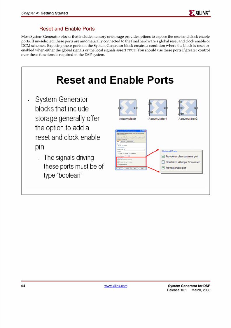
8112019 System Generator for DSP Getting Started
httpslidepdfcomreaderfullsystem-generator-for-dsp-getting-started 6693
66 wwwxilinxcom System Generator for DSPRelease 101 March 2008
Chapter 4 Getting Started R
Lesson 3 Summary
bull Use the MCode block for state machines and branch conditional logic
bull Use the Expression block to implement logical control at the bit level
bull Storage elements have the ability to include optional reset and clock enable pins thatcan be connected in System Generator
bull Blocks that operate on bursty data include data flow control pins called vin and vout
Lab Exercise System Control
In this lab you will be creating a simple state machine using the MCode block to detect asequence of binary values ldquo1011rdquo The FSM needs to be able to detect multipletransmissions as well ie ldquo10111011rdquo
The lab data and instructions are located in the System Generator software tree at thefollowing pathname
ltsysgen_treegtexamplesgetting_started_traininglab4
Lab InstructionsLab Data
8112019 System Generator for DSP Getting Started
httpslidepdfcomreaderfullsystem-generator-for-dsp-getting-started 6793
System Generator for DSP wwwxilinxcom 67Release 101 March 2008
Lesson 4 - Multi-Rate SystemsR
Lesson 4 - Multi-Rate Systems
Creating Multi-Rate Systems
The following illustration shows a typical base-station receiver The tower has multiple antennas to providesectored coverage of the area The diagram shows that this results in two receiver channels In each of these
channels there is some form of complex mixing resulting in real and imaginary channels
Often DSP systems such as this will down sample the input signals prior to the digital filtering steps performedduring equalization and demodulation Doing so can simplify the filter design and hardware significantly Thesesystems are referred to as ldquomulti-raterdquo systems
8112019 System Generator for DSP Getting Started
httpslidepdfcomreaderfullsystem-generator-for-dsp-getting-started 6893
68 wwwxilinxcom System Generator for DSPRelease 101 March 2008
Chapter 4 Getting Started R
Up and Down Sampling Blocks
System Generator includes Up Sample and Down Sample blocks that change the system sample rate The UpSample block adds additional samples to the signal to achieve the desired rate change The value of these newsamples is either zero or the value of the last actual sample depending on the block options The Down Sample block simply discards samples until it achieves the desired rate change For example downsample by 3 means todiscard 2 out of every 3 samples
8112019 System Generator for DSP Getting Started
httpslidepdfcomreaderfullsystem-generator-for-dsp-getting-started 6993
System Generator for DSP wwwxilinxcom 69Release 101 March 2008
Lesson 4 - Multi-Rate SystemsR
Rate Changing Functional Blocks
In addition to the straightforward ldquoUp Samplerdquo and ldquoDown Samplerdquo blocks System Generator also provides ratechanging functional blocks that is blocks that also perform a specific function The Parallel to Serial block will upsample the Serial to Parallel block will down sample the FIR Compiler if using a resource-shared multiplier willdown sample and the TDM block will up sample
8112019 System Generator for DSP Getting Started
httpslidepdfcomreaderfullsystem-generator-for-dsp-getting-started 7093
70 wwwxilinxcom System Generator for DSPRelease 101 March 2008
Chapter 4 Getting Started R
Viewing Rate Changes in Simulink
Simulink supports viewing different sample times as different colors which is fully supported for System Generator blocks To enable the Sample Time Colors feature select the pulldown menu Format gt Sample Time Colors TheSimulink tool does not automatically recolor the model with each change you make to it so you must select Edit gtUpdate Diagram to explicitly update the model coloration To return to your original coloring disable the sampletime coloration by again choosing Sample Time Colors
8112019 System Generator for DSP Getting Started
httpslidepdfcomreaderfullsystem-generator-for-dsp-getting-started 7193
System Generator for DSP wwwxilinxcom 71Release 101 March 2008
Lesson 4 - Multi-Rate SystemsR
Debugging Tools
System Generator provides 3 debugging utilities to assist in debugging complex multi-rate systems
The Sample Time (ST) probe can be connected to any System Generator signal then to a Simulink ldquodisplayrdquo blockfrom the ldquoSinksrdquo library The sample time for the connected net will appear in the display
The clk probe is not connected to any inputs but only to a scope output It displays the master clock This can beused with the Clock Enable Probe to display the behavior of the clock enable signal at various points in the downsampling
8112019 System Generator for DSP Getting Started
httpslidepdfcomreaderfullsystem-generator-for-dsp-getting-started 7293
72 wwwxilinxcom System Generator for DSPRelease 101 March 2008
Chapter 4 Getting Started R
Sample Period ldquoRulesrdquo
The illustration below is an example of a multi-rate system that demonstrates how the Simulink System Period can be calculated and entered into the System Generator token GUI
If you get it wrong there is a sampling period analyzer that automatically determines the appropriate sampleperiod and prompts you to update the GUI
8112019 System Generator for DSP Getting Started
httpslidepdfcomreaderfullsystem-generator-for-dsp-getting-started 7393
System Generator for DSP wwwxilinxcom 73Release 101 March 2008
Lesson 4 - Multi-Rate SystemsR
Lab Exercise Multi-Rate Systems
In this lab you will be exploring the effects of the rate changing blocks available in SystemGenerator These blocks include Upsample Downsample Serial to Parallel and Parallel toSerial
The lab instructions and lab design are located in the System Generator software tree at the
following pathnameltsysgen_treegtexamplesgetting_started_traininglab5
Lab Instructions
Lab Design
8112019 System Generator for DSP Getting Started
httpslidepdfcomreaderfullsystem-generator-for-dsp-getting-started 7493
74 wwwxilinxcom System Generator for DSPRelease 101 March 2008
Chapter 4 Getting Started R
Lesson 5 - Using Memories
Block vs Distributed RAM
Xilinx FPGAs offer two distinct memory options Block RAM and Distributed RAM Block RAM uses dedicatedon-chip hardware resources and represents the most area-efficient RAM implementation Block RAMs offer high
performance but due to their fixed location on the chip may incur slightly larger routing delays Distributed RAMuses the lookup tables in the FPGA slices to implement memory and in doing so will subtract from the slicesavailable for logical operations Because Distributed RAM can be located anywhere throughout the chip routingdelays can be minimized and slightly higher performance can be achieved Distributed RAM is an excellent optionfor small FIFOs
8112019 System Generator for DSP Getting Started
httpslidepdfcomreaderfullsystem-generator-for-dsp-getting-started 7593
System Generator for DSP wwwxilinxcom 75Release 101 March 2008
Lesson 5 - Using MemoriesR
Initializing RAMs and ROMs
The RAM and ROM blocks can be initialized to a 1xn vector that matches the depth of the RAM MATLAB is usedto set the initial value vector Any MATLAB statement can be used that results in a 1xn vector including the filereading commands such as imread auread wavread and load
8112019 System Generator for DSP Getting Started
httpslidepdfcomreaderfullsystem-generator-for-dsp-getting-started 7693
8112019 System Generator for DSP Getting Started
httpslidepdfcomreaderfullsystem-generator-for-dsp-getting-started 7793
System Generator for DSP wwwxilinxcom 77Release 101 March 2008
Lesson 5 - Using MemoriesR
System Generator ROM Blocks
The ROM block supports an implementation in either Block- or Distributed RAM and is initialized through aMATLAB command The signal connected to the address port must be unsigned with no fractional bits
8112019 System Generator for DSP Getting Started
httpslidepdfcomreaderfullsystem-generator-for-dsp-getting-started 7893
78 wwwxilinxcom System Generator for DSPRelease 101 March 2008
Chapter 4 Getting Started R
The Delay Block
The Delay block is used to synchronize dataflow through the FPGA This block maps to a highly-efficient shiftregister structure built from a slice lookup table called an SRL16 that is 85 smaller than using registers
8112019 System Generator for DSP Getting Started
httpslidepdfcomreaderfullsystem-generator-for-dsp-getting-started 7993
System Generator for DSP wwwxilinxcom 79Release 101 March 2008
Lesson 5 - Using MemoriesR
The FIFO Block
The FIFO block supports both Block RAM and Distributed RAM implementations Depths up to 64K are supportedThree output flags are supported empty full and full The full flag is set depending on a bit widthspecification One bit will be zero until the FIFO is 50 full then it will set to5 Two bits will be zero until 20 fullthen 25 5 and 75
8112019 System Generator for DSP Getting Started
httpslidepdfcomreaderfullsystem-generator-for-dsp-getting-started 8093
80 wwwxilinxcom System Generator for DSPRelease 101 March 2008
Chapter 4 Getting Started R
Lab Exercise Using Memories
In this lab you will learn how to use a Xilinx ROM block to implement a LUT-basedoperation such as an Arcsin using Block RAM or Distributed RAM This provides anefficient implementation for trig and math functions with inputs that can be quantized to10 bits or less
The lab instructions and lab design are located in the System Generator software tree at thefollowing pathname
ltsysgen_treegtexamplesgetting_started_traininglab6
Lab Instructions
Lab Design
8112019 System Generator for DSP Getting Started
httpslidepdfcomreaderfullsystem-generator-for-dsp-getting-started 8193
System Generator for DSP wwwxilinxcom 81Release 101 March 2008
Lesson 6 - Designing FiltersR
Lesson 6 - Designing Filters
Introduction
Digital filters are a common DSP operation and especially well suited to implementation in FPGAs High-performance applications benefit greatly from parallel filters that can return a results on every clock cycle The
Virtex 5 device includes up to 550 parallel multipliers The FIR Compiler is designed to use these multipliers in themost efficient manner for creating commonly used FIR filters An alternative implementation is available calledldquodistributed arithmeticrdquo that creates FIR filters without using multipliers by employing a shift-add technique Thiscan be used for smaller devices when the available multipliers have been allocated to other functions
8112019 System Generator for DSP Getting Started
httpslidepdfcomreaderfullsystem-generator-for-dsp-getting-started 8293
82 wwwxilinxcom System Generator for DSPRelease 101 March 2008
Chapter 4 Getting Started R
The Virtex DSP48 Math Slice
The Virtextrade family introduces a high-performance arithmetic unit along with a multiplier the low-power DSP48slice The following figure is a detailed diagram of the DSP48 structure The DSP48 slice consists of four mainsections (1) IO registers (2) signed multiplier (3) three-input addersubtractor and (4) OPMODE multiplexers
8112019 System Generator for DSP Getting Started
httpslidepdfcomreaderfullsystem-generator-for-dsp-getting-started 8393
System Generator for DSP wwwxilinxcom 83Release 101 March 2008
Lesson 6 - Designing FiltersR
FIR Compiler Block
The Xilinx Fir Compiler v1_0 block implements a high speed MAC based FIR filter It accepts a stream of input dataand computes filtered output with a fixed delay based on the filter configuration The FIR Compiler supportsgeneration of resource shared or parallel FIR structures and polyphase decimation and interpolation structuresAlso supported is oversampling Coefficients are specified using MATLAB commands
8112019 System Generator for DSP Getting Started
httpslidepdfcomreaderfullsystem-generator-for-dsp-getting-started 8493
84 wwwxilinxcom System Generator for DSPRelease 101 March 2008
Chapter 4 Getting Started R
Creating Coefficients with FDATool
The Mathworks FDATool is a graphical filter design program that can be used to generate coefficients for the FIRCompiler block
8112019 System Generator for DSP Getting Started
httpslidepdfcomreaderfullsystem-generator-for-dsp-getting-started 8593
System Generator for DSP wwwxilinxcom 85Release 101 March 2008
Lesson 6 - Designing FiltersR
Using FDA Tool Coefficients
Once a suitable filter response has been designed you simply export the coefficients to the workspace using theFile gt Export command The workspace variable can then be referenced in the FIR Compiler properties editor
8112019 System Generator for DSP Getting Started
httpslidepdfcomreaderfullsystem-generator-for-dsp-getting-started 8693
86 wwwxilinxcom System Generator for DSPRelease 101 March 2008
Chapter 4 Getting Started R
Lab Exercise Designing Filters
In this lab you will be using the Filter Compiler block to generate optimized filters for theVirtex4 architecture
The lab instructions and lab design are located in the System Generator software tree at thefollowing pathname
ltsysgen_treegtexamplesgetting_started_traininglab7
Lab Instructions
Lab Design
8112019 System Generator for DSP Getting Started
httpslidepdfcomreaderfullsystem-generator-for-dsp-getting-started 8793
System Generator for DSP wwwxilinxcom 87Release 101 March 2008
Additional Examples and TutorialsR
Additional Examples and Tutorials
Numerous examples are used to illustrate System Generator features and functions in theSystem Generator documentaton These examples are found in the directory at pathnameltsysgen_treegtexamples and are listed in the table below In addition to theseexamples System Generator also includes demonstration models that can be run from the
demo page Enter the following command at the MATLAB promptdemo blocksets xilinx
Note If you are using the MATLAB help browser you can open and run the examples directly fromthis page To run an example click on the link MATLAB will change directories to the exampledirectory and open the example model
Black Box Examples
ChipScope Examples
Topic Description
Importing a VHDL
Module
A tutorial showing how to use the black box to import VHDL into a
System Generator design and how to use ModelSim to co-simulatethe VHDL module
Simulating SeveralBlack BoxesSimultaneously
Shows how black boxes can co-simulate simultaneously using onlyone ModelSim license
Dynamic Black Boxes A tutorial showing how to parameterize the black box
Importing a VerilogModule
A tutorial showing how to use the black box to import Verilog intoa System Generator design and how to use ModelSim to co-simulatethe Verilog module
Importing a Xilinx
Core GeneratorModule
A tutorial showing how to import a COREGEN module as a black
box
Topic Description
Using ChipScope ProAnalyzer for Real-Time HardwareDebugging
This tutorial demonstrates how to connect and use the Xilinx DebugTool called ChipScope Pro within Xilinx System Generator Theintegration of ChipScope Pro in the System Generator flow allowsreal-time debugging at system speed
8112019 System Generator for DSP Getting Started
httpslidepdfcomreaderfullsystem-generator-for-dsp-getting-started 8893
88 wwwxilinxcom System Generator for DSPRelease 101 March 2008
Chapter 4 Getting Started R
DSP Examples
Topic Description
DSP48 Block Simple example demonstrating the use of the DSP48 block with the
Constant block used to provide the DSP48 instruction
DSP48 Macro Block Simple example demonstrating how to use a DSP48 Macro block toimplement a Complex Multiplier
DSP48 Block
(35-Bit Multiplierusing DSP48 andConstant block)
This design demonstrates the use of the DSP48 and Constant blockin implementing 35 by 35-bit multipliers at different sample ratesThree multipliers implementations are shown at 1 2 and 4 clocksper sample
DSP48 Macro Block
(FIR filter using theDSP48 Macro block as
a multiply accumulatefunction)
This design demonstrates the use of the DSP48 Macro block inimplementing a 35 by 35 Multiplier
DSP48 Block
FIR filter examplesusing DSP48 block
This design demonstrates the use of the DSP48 and Constant blockin FIR filter implementation The design includes sets of parallelsemi-parallel and sequential FIR filter using Type 1 and Type 2architectures Each filter implements a 16-tap dsp48-based FIRfilters
DSP48 DesignTechniques
(DSP48-baseddynamic shifter)
This design demonstrates the use of the DSP48 block inimplementing a 35-bit signed right shift using 2 DSP48s
DSP48 DesignTechniques
(Synthesizable FIRfilter for Virtex4)
This design demonstrates how to use System Generator toimplement a synthesizable FIR filter which maps efficiently to theVirtex4 architecture
DSP48 Macro Block
(FIR filter using theDSP48 Macro block asa multiply accumulatefunction)
This design demonstrates the use of the DSP48 Macro block whenimplementing a sequential FIR filter
MAC FIR filter This design example implements a 43 tap FIR Filter with a MACengine and a Dual Port Ram used for data and coefficient storage
Complex FIR filter This example demonstrates a complex FIR filter built out of blocksfrom the System Generator and Simulink library
8112019 System Generator for DSP Getting Started
httpslidepdfcomreaderfullsystem-generator-for-dsp-getting-started 8993
System Generator for DSP wwwxilinxcom 89Release 101 March 2008
Additional Examples and TutorialsR
M-Code Examples
Processor Examples
Topic Description
Simple Selector This example shows how to implement a function that returns the
maximum value of its inputsSimple ArithmeticOperations
This example shows how to implement simple arithmeticoperations
Complex Multiplierwith Latency
This example shows how to build a complex multiplier with latency
Shift Operations This example shows how to implement shift operations
Passing Parametersinto the MCode Block
This example shows how to pass parameters into a MCode block
Optional Input Ports This example shows how to implement optional input ports on an
MCode blockFinite State Machines This example shows how to implement a finite state machine
ParameterizableAccumulator
This example shows how to build a parameterizable accumulator
FIR Blocks andVerification
This example shows how to model FIR blocks and how to do systemverification
RPN Calculator This example shows how to model a RPN calculator ndash a stackmachine
Example of disp
function
This example shows how to use the disp function
Topic Description
Designing andExporting MicroBlazeProcessor Peripherals
Demonstrates how to export a design from System Generator intoXilinx Platform Studio (EDK) by showing how to design aperipheral (pcore) for a MicroBlaze processor An RGB to gray-scalecolor space converter is created and generated into a pcore using theExport to EDK compilation target
8112019 System Generator for DSP Getting Started
httpslidepdfcomreaderfullsystem-generator-for-dsp-getting-started 9093
90 wwwxilinxcom System Generator for DSPRelease 101 March 2008
Chapter 4 Getting Started R
Shared Memory Examples
Tutorial Example -Designing andSimulatingMicroBlaze ProcessorSystems
Demonstrates how to import a MicroBlaze processor created usingXilinx Platform Studio into System Generator A DSP48 block isused as a co-processor to the MicroBlaze
Designing PicoBlazeMicrocontrollerApplications
Demonstrates how to implement a PicoBlaze program in SystemGenerator The example programs the PicoBlaze to alter the outputfrequency of a Direct Digital Synthesizer (DDS) during an interrupt
Topic Description
Topic Description
Simulation across
various models
Illustrates shared memories communicating across Simulink
models
Host PC SharedMemory access
Developer studio project to communicate with a shared memory
High Speed VideoProcessing usingHardware Co-simulation
Discussion of a high-speed co-simulation buffering interfacefollowed by an example in which the interface is used to supportreal-time processing of a video stream using a 5x5 filter kernel
High speed IOBuffering
Illustrates high speed Shared Memory IO Buffering Interface forHardware Co-simulation
SharedMemory
(Mex-functioninterface)
Illustrates the use of a mex-function as an interface to a sharedmemory
Generating MultipleCycle-True Islands forDistinct Clocks
An example using two asynchronous clocks
Shared Memory ToFIFO To Register ToRegister FromRegister
Demonstrates use of shared memories FIFOs and registers to passinformation
Frame-BasedAcceleration usingHardware Co-
Simulation
Explains how to use frame or vector-based transfers to furtheraccelerate simulations using FPGA hardware co-simulation
8112019 System Generator for DSP Getting Started
httpslidepdfcomreaderfullsystem-generator-for-dsp-getting-started 9193
System Generator for DSP wwwxilinxcom 91Release 101 March 2008
Additional Examples and TutorialsR
Timing Analysis Examples
Miscellaneous Examples
Topic Description
Timing Analysis
Tutorial
Explains how to use the System Generator Timing Analysis tool to
meet timing requirements of System Generator designs Alsotouches on techniques that may be used when a design does notmeet timing
Topic Description
Importing a SystemGenerator Design intoa Bigger System
Discusses how to take the VHDL netlist from a System Generatordesign and synthesize it in order to embed it into a larger designAlso shows how VHDL created by System Generator can beincorporated into simulation model of the overall system
ConfigurableSubsystems andSystem Generator
Illustrates the use of Configurable Subsystems for Simulation andGeneration
Integrator This example uses an integrator to illustrate error analysiscapability
Block RAM-BasedState Machines
Demonstrates use of Mealy State Machine block from the referencelibrary
8112019 System Generator for DSP Getting Started
httpslidepdfcomreaderfullsystem-generator-for-dsp-getting-started 9293
92 wwwxilinxcom System Generator for DSPRelease 101 March 2008
Chapter 4 Getting Started R
System Generator Demos
System Generator for DSP provides the capability to model and implement high-performance DSP systems in field- programmable gate arrays (FPGAs) using SimulinkThe Xilinx Blockset contains bit and cycle-true models of arithmetic and logic functionsmemories and DSP functions for digital filtering spectral analysis and digitalcommunications System Generator converts a Simulink model of Xilinx blocks into anefficient hardware implementation that combines synthesizable VHDL and intellectualproperty blocks that have been hand-crafted to run efficiently in FPGAs
Included with the tool are numerous demonstration designs that highlight key featuresand tool capabilities as well as general good design practices using real-world designapplications These designs may be accessed from the System Generator demo page Enterthe following command at the MATLAB prompt
demo blocksets xilinx
8112019 System Generator for DSP Getting Started
httpslidepdfcomreaderfullsystem-generator-for-dsp-getting-started 9393
AAsynchronous Software Drivers
for FSLs 25
CCompatibility
MATLAB 24 29 34 36
ModelSim 24 29 34 36
Synplify Pro 24 29 34 36
Compiling
Xilinx HDL Libraries 21
Configuring
the Sysgen cache 21
Custom Bus Interfacesfor exported pcore 26
DDownloading
System Generator 19
EExport pcore
enable Custom Bus Interfaces 26
FFast Simplex Link
asynchronous software drivers for 25
H
MMATLAB 24 29 34 36
Memory Stitching 31ModelSim 24 29 34 36
PPcore
export as under development 26
SShared Memory Stitching 31
Software Drivers
asynchronous for FSLs 25System Generator
Cache 21
changing versions 21
displaying versions 21
downloading the software 19
ISE Design Suite Installer 20
System Generator Utilities
xlUpdateModel 37
U
Underdevelopmentexport pcore as 26
XXilinx HDL Libraries
compiling 21
xlUpdateModel 37
Index
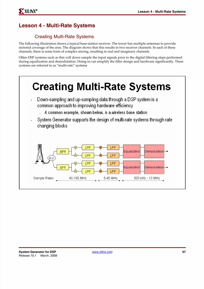
8112019 System Generator for DSP Getting Started
httpslidepdfcomreaderfullsystem-generator-for-dsp-getting-started 7593
System Generator for DSP wwwxilinxcom 75Release 101 March 2008
Lesson 5 - Using MemoriesR
Initializing RAMs and ROMs
The RAM and ROM blocks can be initialized to a 1xn vector that matches the depth of the RAM MATLAB is usedto set the initial value vector Any MATLAB statement can be used that results in a 1xn vector including the filereading commands such as imread auread wavread and load
8112019 System Generator for DSP Getting Started
httpslidepdfcomreaderfullsystem-generator-for-dsp-getting-started 7693
8112019 System Generator for DSP Getting Started
httpslidepdfcomreaderfullsystem-generator-for-dsp-getting-started 7793
System Generator for DSP wwwxilinxcom 77Release 101 March 2008
Lesson 5 - Using MemoriesR
System Generator ROM Blocks
The ROM block supports an implementation in either Block- or Distributed RAM and is initialized through aMATLAB command The signal connected to the address port must be unsigned with no fractional bits
8112019 System Generator for DSP Getting Started
httpslidepdfcomreaderfullsystem-generator-for-dsp-getting-started 7893
78 wwwxilinxcom System Generator for DSPRelease 101 March 2008
Chapter 4 Getting Started R
The Delay Block
The Delay block is used to synchronize dataflow through the FPGA This block maps to a highly-efficient shiftregister structure built from a slice lookup table called an SRL16 that is 85 smaller than using registers
8112019 System Generator for DSP Getting Started
httpslidepdfcomreaderfullsystem-generator-for-dsp-getting-started 7993
System Generator for DSP wwwxilinxcom 79Release 101 March 2008
Lesson 5 - Using MemoriesR
The FIFO Block
The FIFO block supports both Block RAM and Distributed RAM implementations Depths up to 64K are supportedThree output flags are supported empty full and full The full flag is set depending on a bit widthspecification One bit will be zero until the FIFO is 50 full then it will set to5 Two bits will be zero until 20 fullthen 25 5 and 75
8112019 System Generator for DSP Getting Started
httpslidepdfcomreaderfullsystem-generator-for-dsp-getting-started 8093
80 wwwxilinxcom System Generator for DSPRelease 101 March 2008
Chapter 4 Getting Started R
Lab Exercise Using Memories
In this lab you will learn how to use a Xilinx ROM block to implement a LUT-basedoperation such as an Arcsin using Block RAM or Distributed RAM This provides anefficient implementation for trig and math functions with inputs that can be quantized to10 bits or less
The lab instructions and lab design are located in the System Generator software tree at thefollowing pathname
ltsysgen_treegtexamplesgetting_started_traininglab6
Lab Instructions
Lab Design
8112019 System Generator for DSP Getting Started
httpslidepdfcomreaderfullsystem-generator-for-dsp-getting-started 8193
System Generator for DSP wwwxilinxcom 81Release 101 March 2008
Lesson 6 - Designing FiltersR
Lesson 6 - Designing Filters
Introduction
Digital filters are a common DSP operation and especially well suited to implementation in FPGAs High-performance applications benefit greatly from parallel filters that can return a results on every clock cycle The
Virtex 5 device includes up to 550 parallel multipliers The FIR Compiler is designed to use these multipliers in themost efficient manner for creating commonly used FIR filters An alternative implementation is available calledldquodistributed arithmeticrdquo that creates FIR filters without using multipliers by employing a shift-add technique Thiscan be used for smaller devices when the available multipliers have been allocated to other functions
8112019 System Generator for DSP Getting Started
httpslidepdfcomreaderfullsystem-generator-for-dsp-getting-started 8293
82 wwwxilinxcom System Generator for DSPRelease 101 March 2008
Chapter 4 Getting Started R
The Virtex DSP48 Math Slice
The Virtextrade family introduces a high-performance arithmetic unit along with a multiplier the low-power DSP48slice The following figure is a detailed diagram of the DSP48 structure The DSP48 slice consists of four mainsections (1) IO registers (2) signed multiplier (3) three-input addersubtractor and (4) OPMODE multiplexers
8112019 System Generator for DSP Getting Started
httpslidepdfcomreaderfullsystem-generator-for-dsp-getting-started 8393
System Generator for DSP wwwxilinxcom 83Release 101 March 2008
Lesson 6 - Designing FiltersR
FIR Compiler Block
The Xilinx Fir Compiler v1_0 block implements a high speed MAC based FIR filter It accepts a stream of input dataand computes filtered output with a fixed delay based on the filter configuration The FIR Compiler supportsgeneration of resource shared or parallel FIR structures and polyphase decimation and interpolation structuresAlso supported is oversampling Coefficients are specified using MATLAB commands
8112019 System Generator for DSP Getting Started
httpslidepdfcomreaderfullsystem-generator-for-dsp-getting-started 8493
84 wwwxilinxcom System Generator for DSPRelease 101 March 2008
Chapter 4 Getting Started R
Creating Coefficients with FDATool
The Mathworks FDATool is a graphical filter design program that can be used to generate coefficients for the FIRCompiler block
8112019 System Generator for DSP Getting Started
httpslidepdfcomreaderfullsystem-generator-for-dsp-getting-started 8593
System Generator for DSP wwwxilinxcom 85Release 101 March 2008
Lesson 6 - Designing FiltersR
Using FDA Tool Coefficients
Once a suitable filter response has been designed you simply export the coefficients to the workspace using theFile gt Export command The workspace variable can then be referenced in the FIR Compiler properties editor
8112019 System Generator for DSP Getting Started
httpslidepdfcomreaderfullsystem-generator-for-dsp-getting-started 8693
86 wwwxilinxcom System Generator for DSPRelease 101 March 2008
Chapter 4 Getting Started R
Lab Exercise Designing Filters
In this lab you will be using the Filter Compiler block to generate optimized filters for theVirtex4 architecture
The lab instructions and lab design are located in the System Generator software tree at thefollowing pathname
ltsysgen_treegtexamplesgetting_started_traininglab7
Lab Instructions
Lab Design
8112019 System Generator for DSP Getting Started
httpslidepdfcomreaderfullsystem-generator-for-dsp-getting-started 8793
System Generator for DSP wwwxilinxcom 87Release 101 March 2008
Additional Examples and TutorialsR
Additional Examples and Tutorials
Numerous examples are used to illustrate System Generator features and functions in theSystem Generator documentaton These examples are found in the directory at pathnameltsysgen_treegtexamples and are listed in the table below In addition to theseexamples System Generator also includes demonstration models that can be run from the
demo page Enter the following command at the MATLAB promptdemo blocksets xilinx
Note If you are using the MATLAB help browser you can open and run the examples directly fromthis page To run an example click on the link MATLAB will change directories to the exampledirectory and open the example model
Black Box Examples
ChipScope Examples
Topic Description
Importing a VHDL
Module
A tutorial showing how to use the black box to import VHDL into a
System Generator design and how to use ModelSim to co-simulatethe VHDL module
Simulating SeveralBlack BoxesSimultaneously
Shows how black boxes can co-simulate simultaneously using onlyone ModelSim license
Dynamic Black Boxes A tutorial showing how to parameterize the black box
Importing a VerilogModule
A tutorial showing how to use the black box to import Verilog intoa System Generator design and how to use ModelSim to co-simulatethe Verilog module
Importing a Xilinx
Core GeneratorModule
A tutorial showing how to import a COREGEN module as a black
box
Topic Description
Using ChipScope ProAnalyzer for Real-Time HardwareDebugging
This tutorial demonstrates how to connect and use the Xilinx DebugTool called ChipScope Pro within Xilinx System Generator Theintegration of ChipScope Pro in the System Generator flow allowsreal-time debugging at system speed
8112019 System Generator for DSP Getting Started
httpslidepdfcomreaderfullsystem-generator-for-dsp-getting-started 8893
88 wwwxilinxcom System Generator for DSPRelease 101 March 2008
Chapter 4 Getting Started R
DSP Examples
Topic Description
DSP48 Block Simple example demonstrating the use of the DSP48 block with the
Constant block used to provide the DSP48 instruction
DSP48 Macro Block Simple example demonstrating how to use a DSP48 Macro block toimplement a Complex Multiplier
DSP48 Block
(35-Bit Multiplierusing DSP48 andConstant block)
This design demonstrates the use of the DSP48 and Constant blockin implementing 35 by 35-bit multipliers at different sample ratesThree multipliers implementations are shown at 1 2 and 4 clocksper sample
DSP48 Macro Block
(FIR filter using theDSP48 Macro block as
a multiply accumulatefunction)
This design demonstrates the use of the DSP48 Macro block inimplementing a 35 by 35 Multiplier
DSP48 Block
FIR filter examplesusing DSP48 block
This design demonstrates the use of the DSP48 and Constant blockin FIR filter implementation The design includes sets of parallelsemi-parallel and sequential FIR filter using Type 1 and Type 2architectures Each filter implements a 16-tap dsp48-based FIRfilters
DSP48 DesignTechniques
(DSP48-baseddynamic shifter)
This design demonstrates the use of the DSP48 block inimplementing a 35-bit signed right shift using 2 DSP48s
DSP48 DesignTechniques
(Synthesizable FIRfilter for Virtex4)
This design demonstrates how to use System Generator toimplement a synthesizable FIR filter which maps efficiently to theVirtex4 architecture
DSP48 Macro Block
(FIR filter using theDSP48 Macro block asa multiply accumulatefunction)
This design demonstrates the use of the DSP48 Macro block whenimplementing a sequential FIR filter
MAC FIR filter This design example implements a 43 tap FIR Filter with a MACengine and a Dual Port Ram used for data and coefficient storage
Complex FIR filter This example demonstrates a complex FIR filter built out of blocksfrom the System Generator and Simulink library
8112019 System Generator for DSP Getting Started
httpslidepdfcomreaderfullsystem-generator-for-dsp-getting-started 8993
System Generator for DSP wwwxilinxcom 89Release 101 March 2008
Additional Examples and TutorialsR
M-Code Examples
Processor Examples
Topic Description
Simple Selector This example shows how to implement a function that returns the
maximum value of its inputsSimple ArithmeticOperations
This example shows how to implement simple arithmeticoperations
Complex Multiplierwith Latency
This example shows how to build a complex multiplier with latency
Shift Operations This example shows how to implement shift operations
Passing Parametersinto the MCode Block
This example shows how to pass parameters into a MCode block
Optional Input Ports This example shows how to implement optional input ports on an
MCode blockFinite State Machines This example shows how to implement a finite state machine
ParameterizableAccumulator
This example shows how to build a parameterizable accumulator
FIR Blocks andVerification
This example shows how to model FIR blocks and how to do systemverification
RPN Calculator This example shows how to model a RPN calculator ndash a stackmachine
Example of disp
function
This example shows how to use the disp function
Topic Description
Designing andExporting MicroBlazeProcessor Peripherals
Demonstrates how to export a design from System Generator intoXilinx Platform Studio (EDK) by showing how to design aperipheral (pcore) for a MicroBlaze processor An RGB to gray-scalecolor space converter is created and generated into a pcore using theExport to EDK compilation target
8112019 System Generator for DSP Getting Started
httpslidepdfcomreaderfullsystem-generator-for-dsp-getting-started 9093
90 wwwxilinxcom System Generator for DSPRelease 101 March 2008
Chapter 4 Getting Started R
Shared Memory Examples
Tutorial Example -Designing andSimulatingMicroBlaze ProcessorSystems
Demonstrates how to import a MicroBlaze processor created usingXilinx Platform Studio into System Generator A DSP48 block isused as a co-processor to the MicroBlaze
Designing PicoBlazeMicrocontrollerApplications
Demonstrates how to implement a PicoBlaze program in SystemGenerator The example programs the PicoBlaze to alter the outputfrequency of a Direct Digital Synthesizer (DDS) during an interrupt
Topic Description
Topic Description
Simulation across
various models
Illustrates shared memories communicating across Simulink
models
Host PC SharedMemory access
Developer studio project to communicate with a shared memory
High Speed VideoProcessing usingHardware Co-simulation
Discussion of a high-speed co-simulation buffering interfacefollowed by an example in which the interface is used to supportreal-time processing of a video stream using a 5x5 filter kernel
High speed IOBuffering
Illustrates high speed Shared Memory IO Buffering Interface forHardware Co-simulation
SharedMemory
(Mex-functioninterface)
Illustrates the use of a mex-function as an interface to a sharedmemory
Generating MultipleCycle-True Islands forDistinct Clocks
An example using two asynchronous clocks
Shared Memory ToFIFO To Register ToRegister FromRegister
Demonstrates use of shared memories FIFOs and registers to passinformation
Frame-BasedAcceleration usingHardware Co-
Simulation
Explains how to use frame or vector-based transfers to furtheraccelerate simulations using FPGA hardware co-simulation
8112019 System Generator for DSP Getting Started
httpslidepdfcomreaderfullsystem-generator-for-dsp-getting-started 9193
System Generator for DSP wwwxilinxcom 91Release 101 March 2008
Additional Examples and TutorialsR
Timing Analysis Examples
Miscellaneous Examples
Topic Description
Timing Analysis
Tutorial
Explains how to use the System Generator Timing Analysis tool to
meet timing requirements of System Generator designs Alsotouches on techniques that may be used when a design does notmeet timing
Topic Description
Importing a SystemGenerator Design intoa Bigger System
Discusses how to take the VHDL netlist from a System Generatordesign and synthesize it in order to embed it into a larger designAlso shows how VHDL created by System Generator can beincorporated into simulation model of the overall system
ConfigurableSubsystems andSystem Generator
Illustrates the use of Configurable Subsystems for Simulation andGeneration
Integrator This example uses an integrator to illustrate error analysiscapability
Block RAM-BasedState Machines
Demonstrates use of Mealy State Machine block from the referencelibrary
8112019 System Generator for DSP Getting Started
httpslidepdfcomreaderfullsystem-generator-for-dsp-getting-started 9293
92 wwwxilinxcom System Generator for DSPRelease 101 March 2008
Chapter 4 Getting Started R
System Generator Demos
System Generator for DSP provides the capability to model and implement high-performance DSP systems in field- programmable gate arrays (FPGAs) using SimulinkThe Xilinx Blockset contains bit and cycle-true models of arithmetic and logic functionsmemories and DSP functions for digital filtering spectral analysis and digitalcommunications System Generator converts a Simulink model of Xilinx blocks into anefficient hardware implementation that combines synthesizable VHDL and intellectualproperty blocks that have been hand-crafted to run efficiently in FPGAs
Included with the tool are numerous demonstration designs that highlight key featuresand tool capabilities as well as general good design practices using real-world designapplications These designs may be accessed from the System Generator demo page Enterthe following command at the MATLAB prompt
demo blocksets xilinx
8112019 System Generator for DSP Getting Started
httpslidepdfcomreaderfullsystem-generator-for-dsp-getting-started 9393
AAsynchronous Software Drivers
for FSLs 25
CCompatibility
MATLAB 24 29 34 36
ModelSim 24 29 34 36
Synplify Pro 24 29 34 36
Compiling
Xilinx HDL Libraries 21
Configuring
the Sysgen cache 21
Custom Bus Interfacesfor exported pcore 26
DDownloading
System Generator 19
EExport pcore
enable Custom Bus Interfaces 26
FFast Simplex Link
asynchronous software drivers for 25
H
MMATLAB 24 29 34 36
Memory Stitching 31ModelSim 24 29 34 36
PPcore
export as under development 26
SShared Memory Stitching 31
Software Drivers
asynchronous for FSLs 25System Generator
Cache 21
changing versions 21
displaying versions 21
downloading the software 19
ISE Design Suite Installer 20
System Generator Utilities
xlUpdateModel 37
U
Underdevelopmentexport pcore as 26
XXilinx HDL Libraries
compiling 21
xlUpdateModel 37
Index
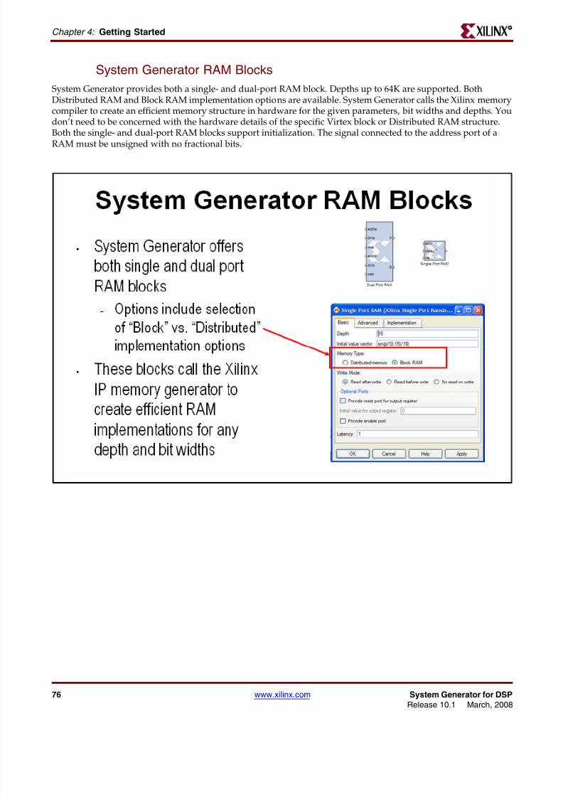
8112019 System Generator for DSP Getting Started
httpslidepdfcomreaderfullsystem-generator-for-dsp-getting-started 7793
System Generator for DSP wwwxilinxcom 77Release 101 March 2008
Lesson 5 - Using MemoriesR
System Generator ROM Blocks
The ROM block supports an implementation in either Block- or Distributed RAM and is initialized through aMATLAB command The signal connected to the address port must be unsigned with no fractional bits
8112019 System Generator for DSP Getting Started
httpslidepdfcomreaderfullsystem-generator-for-dsp-getting-started 7893
78 wwwxilinxcom System Generator for DSPRelease 101 March 2008
Chapter 4 Getting Started R
The Delay Block
The Delay block is used to synchronize dataflow through the FPGA This block maps to a highly-efficient shiftregister structure built from a slice lookup table called an SRL16 that is 85 smaller than using registers
8112019 System Generator for DSP Getting Started
httpslidepdfcomreaderfullsystem-generator-for-dsp-getting-started 7993
System Generator for DSP wwwxilinxcom 79Release 101 March 2008
Lesson 5 - Using MemoriesR
The FIFO Block
The FIFO block supports both Block RAM and Distributed RAM implementations Depths up to 64K are supportedThree output flags are supported empty full and full The full flag is set depending on a bit widthspecification One bit will be zero until the FIFO is 50 full then it will set to5 Two bits will be zero until 20 fullthen 25 5 and 75
8112019 System Generator for DSP Getting Started
httpslidepdfcomreaderfullsystem-generator-for-dsp-getting-started 8093
80 wwwxilinxcom System Generator for DSPRelease 101 March 2008
Chapter 4 Getting Started R
Lab Exercise Using Memories
In this lab you will learn how to use a Xilinx ROM block to implement a LUT-basedoperation such as an Arcsin using Block RAM or Distributed RAM This provides anefficient implementation for trig and math functions with inputs that can be quantized to10 bits or less
The lab instructions and lab design are located in the System Generator software tree at thefollowing pathname
ltsysgen_treegtexamplesgetting_started_traininglab6
Lab Instructions
Lab Design
8112019 System Generator for DSP Getting Started
httpslidepdfcomreaderfullsystem-generator-for-dsp-getting-started 8193
System Generator for DSP wwwxilinxcom 81Release 101 March 2008
Lesson 6 - Designing FiltersR
Lesson 6 - Designing Filters
Introduction
Digital filters are a common DSP operation and especially well suited to implementation in FPGAs High-performance applications benefit greatly from parallel filters that can return a results on every clock cycle The
Virtex 5 device includes up to 550 parallel multipliers The FIR Compiler is designed to use these multipliers in themost efficient manner for creating commonly used FIR filters An alternative implementation is available calledldquodistributed arithmeticrdquo that creates FIR filters without using multipliers by employing a shift-add technique Thiscan be used for smaller devices when the available multipliers have been allocated to other functions
8112019 System Generator for DSP Getting Started
httpslidepdfcomreaderfullsystem-generator-for-dsp-getting-started 8293
82 wwwxilinxcom System Generator for DSPRelease 101 March 2008
Chapter 4 Getting Started R
The Virtex DSP48 Math Slice
The Virtextrade family introduces a high-performance arithmetic unit along with a multiplier the low-power DSP48slice The following figure is a detailed diagram of the DSP48 structure The DSP48 slice consists of four mainsections (1) IO registers (2) signed multiplier (3) three-input addersubtractor and (4) OPMODE multiplexers
8112019 System Generator for DSP Getting Started
httpslidepdfcomreaderfullsystem-generator-for-dsp-getting-started 8393
System Generator for DSP wwwxilinxcom 83Release 101 March 2008
Lesson 6 - Designing FiltersR
FIR Compiler Block
The Xilinx Fir Compiler v1_0 block implements a high speed MAC based FIR filter It accepts a stream of input dataand computes filtered output with a fixed delay based on the filter configuration The FIR Compiler supportsgeneration of resource shared or parallel FIR structures and polyphase decimation and interpolation structuresAlso supported is oversampling Coefficients are specified using MATLAB commands
8112019 System Generator for DSP Getting Started
httpslidepdfcomreaderfullsystem-generator-for-dsp-getting-started 8493
84 wwwxilinxcom System Generator for DSPRelease 101 March 2008
Chapter 4 Getting Started R
Creating Coefficients with FDATool
The Mathworks FDATool is a graphical filter design program that can be used to generate coefficients for the FIRCompiler block
8112019 System Generator for DSP Getting Started
httpslidepdfcomreaderfullsystem-generator-for-dsp-getting-started 8593
System Generator for DSP wwwxilinxcom 85Release 101 March 2008
Lesson 6 - Designing FiltersR
Using FDA Tool Coefficients
Once a suitable filter response has been designed you simply export the coefficients to the workspace using theFile gt Export command The workspace variable can then be referenced in the FIR Compiler properties editor
8112019 System Generator for DSP Getting Started
httpslidepdfcomreaderfullsystem-generator-for-dsp-getting-started 8693
86 wwwxilinxcom System Generator for DSPRelease 101 March 2008
Chapter 4 Getting Started R
Lab Exercise Designing Filters
In this lab you will be using the Filter Compiler block to generate optimized filters for theVirtex4 architecture
The lab instructions and lab design are located in the System Generator software tree at thefollowing pathname
ltsysgen_treegtexamplesgetting_started_traininglab7
Lab Instructions
Lab Design
8112019 System Generator for DSP Getting Started
httpslidepdfcomreaderfullsystem-generator-for-dsp-getting-started 8793
System Generator for DSP wwwxilinxcom 87Release 101 March 2008
Additional Examples and TutorialsR
Additional Examples and Tutorials
Numerous examples are used to illustrate System Generator features and functions in theSystem Generator documentaton These examples are found in the directory at pathnameltsysgen_treegtexamples and are listed in the table below In addition to theseexamples System Generator also includes demonstration models that can be run from the
demo page Enter the following command at the MATLAB promptdemo blocksets xilinx
Note If you are using the MATLAB help browser you can open and run the examples directly fromthis page To run an example click on the link MATLAB will change directories to the exampledirectory and open the example model
Black Box Examples
ChipScope Examples
Topic Description
Importing a VHDL
Module
A tutorial showing how to use the black box to import VHDL into a
System Generator design and how to use ModelSim to co-simulatethe VHDL module
Simulating SeveralBlack BoxesSimultaneously
Shows how black boxes can co-simulate simultaneously using onlyone ModelSim license
Dynamic Black Boxes A tutorial showing how to parameterize the black box
Importing a VerilogModule
A tutorial showing how to use the black box to import Verilog intoa System Generator design and how to use ModelSim to co-simulatethe Verilog module
Importing a Xilinx
Core GeneratorModule
A tutorial showing how to import a COREGEN module as a black
box
Topic Description
Using ChipScope ProAnalyzer for Real-Time HardwareDebugging
This tutorial demonstrates how to connect and use the Xilinx DebugTool called ChipScope Pro within Xilinx System Generator Theintegration of ChipScope Pro in the System Generator flow allowsreal-time debugging at system speed
8112019 System Generator for DSP Getting Started
httpslidepdfcomreaderfullsystem-generator-for-dsp-getting-started 8893
88 wwwxilinxcom System Generator for DSPRelease 101 March 2008
Chapter 4 Getting Started R
DSP Examples
Topic Description
DSP48 Block Simple example demonstrating the use of the DSP48 block with the
Constant block used to provide the DSP48 instruction
DSP48 Macro Block Simple example demonstrating how to use a DSP48 Macro block toimplement a Complex Multiplier
DSP48 Block
(35-Bit Multiplierusing DSP48 andConstant block)
This design demonstrates the use of the DSP48 and Constant blockin implementing 35 by 35-bit multipliers at different sample ratesThree multipliers implementations are shown at 1 2 and 4 clocksper sample
DSP48 Macro Block
(FIR filter using theDSP48 Macro block as
a multiply accumulatefunction)
This design demonstrates the use of the DSP48 Macro block inimplementing a 35 by 35 Multiplier
DSP48 Block
FIR filter examplesusing DSP48 block
This design demonstrates the use of the DSP48 and Constant blockin FIR filter implementation The design includes sets of parallelsemi-parallel and sequential FIR filter using Type 1 and Type 2architectures Each filter implements a 16-tap dsp48-based FIRfilters
DSP48 DesignTechniques
(DSP48-baseddynamic shifter)
This design demonstrates the use of the DSP48 block inimplementing a 35-bit signed right shift using 2 DSP48s
DSP48 DesignTechniques
(Synthesizable FIRfilter for Virtex4)
This design demonstrates how to use System Generator toimplement a synthesizable FIR filter which maps efficiently to theVirtex4 architecture
DSP48 Macro Block
(FIR filter using theDSP48 Macro block asa multiply accumulatefunction)
This design demonstrates the use of the DSP48 Macro block whenimplementing a sequential FIR filter
MAC FIR filter This design example implements a 43 tap FIR Filter with a MACengine and a Dual Port Ram used for data and coefficient storage
Complex FIR filter This example demonstrates a complex FIR filter built out of blocksfrom the System Generator and Simulink library
8112019 System Generator for DSP Getting Started
httpslidepdfcomreaderfullsystem-generator-for-dsp-getting-started 8993
System Generator for DSP wwwxilinxcom 89Release 101 March 2008
Additional Examples and TutorialsR
M-Code Examples
Processor Examples
Topic Description
Simple Selector This example shows how to implement a function that returns the
maximum value of its inputsSimple ArithmeticOperations
This example shows how to implement simple arithmeticoperations
Complex Multiplierwith Latency
This example shows how to build a complex multiplier with latency
Shift Operations This example shows how to implement shift operations
Passing Parametersinto the MCode Block
This example shows how to pass parameters into a MCode block
Optional Input Ports This example shows how to implement optional input ports on an
MCode blockFinite State Machines This example shows how to implement a finite state machine
ParameterizableAccumulator
This example shows how to build a parameterizable accumulator
FIR Blocks andVerification
This example shows how to model FIR blocks and how to do systemverification
RPN Calculator This example shows how to model a RPN calculator ndash a stackmachine
Example of disp
function
This example shows how to use the disp function
Topic Description
Designing andExporting MicroBlazeProcessor Peripherals
Demonstrates how to export a design from System Generator intoXilinx Platform Studio (EDK) by showing how to design aperipheral (pcore) for a MicroBlaze processor An RGB to gray-scalecolor space converter is created and generated into a pcore using theExport to EDK compilation target
8112019 System Generator for DSP Getting Started
httpslidepdfcomreaderfullsystem-generator-for-dsp-getting-started 9093
90 wwwxilinxcom System Generator for DSPRelease 101 March 2008
Chapter 4 Getting Started R
Shared Memory Examples
Tutorial Example -Designing andSimulatingMicroBlaze ProcessorSystems
Demonstrates how to import a MicroBlaze processor created usingXilinx Platform Studio into System Generator A DSP48 block isused as a co-processor to the MicroBlaze
Designing PicoBlazeMicrocontrollerApplications
Demonstrates how to implement a PicoBlaze program in SystemGenerator The example programs the PicoBlaze to alter the outputfrequency of a Direct Digital Synthesizer (DDS) during an interrupt
Topic Description
Topic Description
Simulation across
various models
Illustrates shared memories communicating across Simulink
models
Host PC SharedMemory access
Developer studio project to communicate with a shared memory
High Speed VideoProcessing usingHardware Co-simulation
Discussion of a high-speed co-simulation buffering interfacefollowed by an example in which the interface is used to supportreal-time processing of a video stream using a 5x5 filter kernel
High speed IOBuffering
Illustrates high speed Shared Memory IO Buffering Interface forHardware Co-simulation
SharedMemory
(Mex-functioninterface)
Illustrates the use of a mex-function as an interface to a sharedmemory
Generating MultipleCycle-True Islands forDistinct Clocks
An example using two asynchronous clocks
Shared Memory ToFIFO To Register ToRegister FromRegister
Demonstrates use of shared memories FIFOs and registers to passinformation
Frame-BasedAcceleration usingHardware Co-
Simulation
Explains how to use frame or vector-based transfers to furtheraccelerate simulations using FPGA hardware co-simulation
8112019 System Generator for DSP Getting Started
httpslidepdfcomreaderfullsystem-generator-for-dsp-getting-started 9193
System Generator for DSP wwwxilinxcom 91Release 101 March 2008
Additional Examples and TutorialsR
Timing Analysis Examples
Miscellaneous Examples
Topic Description
Timing Analysis
Tutorial
Explains how to use the System Generator Timing Analysis tool to
meet timing requirements of System Generator designs Alsotouches on techniques that may be used when a design does notmeet timing
Topic Description
Importing a SystemGenerator Design intoa Bigger System
Discusses how to take the VHDL netlist from a System Generatordesign and synthesize it in order to embed it into a larger designAlso shows how VHDL created by System Generator can beincorporated into simulation model of the overall system
ConfigurableSubsystems andSystem Generator
Illustrates the use of Configurable Subsystems for Simulation andGeneration
Integrator This example uses an integrator to illustrate error analysiscapability
Block RAM-BasedState Machines
Demonstrates use of Mealy State Machine block from the referencelibrary
8112019 System Generator for DSP Getting Started
httpslidepdfcomreaderfullsystem-generator-for-dsp-getting-started 9293
92 wwwxilinxcom System Generator for DSPRelease 101 March 2008
Chapter 4 Getting Started R
System Generator Demos
System Generator for DSP provides the capability to model and implement high-performance DSP systems in field- programmable gate arrays (FPGAs) using SimulinkThe Xilinx Blockset contains bit and cycle-true models of arithmetic and logic functionsmemories and DSP functions for digital filtering spectral analysis and digitalcommunications System Generator converts a Simulink model of Xilinx blocks into anefficient hardware implementation that combines synthesizable VHDL and intellectualproperty blocks that have been hand-crafted to run efficiently in FPGAs
Included with the tool are numerous demonstration designs that highlight key featuresand tool capabilities as well as general good design practices using real-world designapplications These designs may be accessed from the System Generator demo page Enterthe following command at the MATLAB prompt
demo blocksets xilinx
8112019 System Generator for DSP Getting Started
httpslidepdfcomreaderfullsystem-generator-for-dsp-getting-started 9393
AAsynchronous Software Drivers
for FSLs 25
CCompatibility
MATLAB 24 29 34 36
ModelSim 24 29 34 36
Synplify Pro 24 29 34 36
Compiling
Xilinx HDL Libraries 21
Configuring
the Sysgen cache 21
Custom Bus Interfacesfor exported pcore 26
DDownloading
System Generator 19
EExport pcore
enable Custom Bus Interfaces 26
FFast Simplex Link
asynchronous software drivers for 25
H
MMATLAB 24 29 34 36
Memory Stitching 31ModelSim 24 29 34 36
PPcore
export as under development 26
SShared Memory Stitching 31
Software Drivers
asynchronous for FSLs 25System Generator
Cache 21
changing versions 21
displaying versions 21
downloading the software 19
ISE Design Suite Installer 20
System Generator Utilities
xlUpdateModel 37
U
Underdevelopmentexport pcore as 26
XXilinx HDL Libraries
compiling 21
xlUpdateModel 37
Index
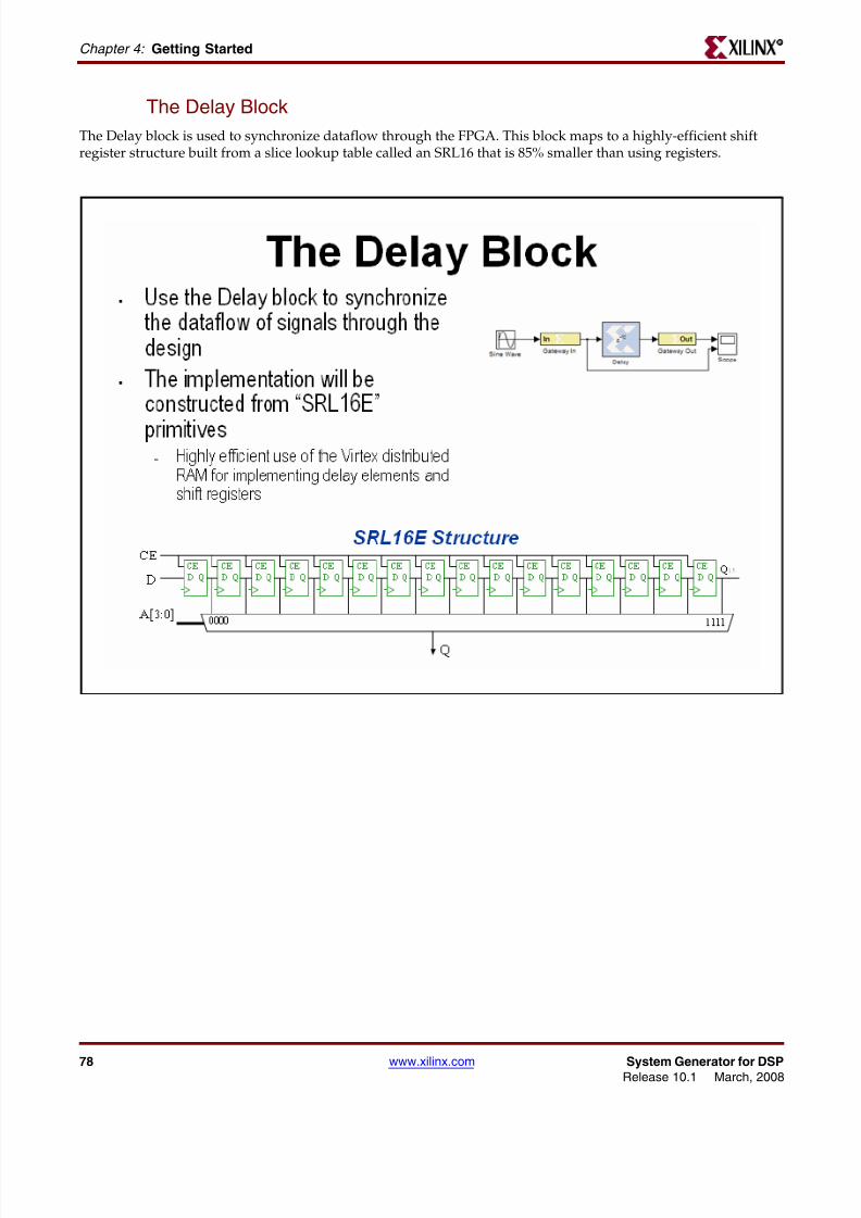
8112019 System Generator for DSP Getting Started
httpslidepdfcomreaderfullsystem-generator-for-dsp-getting-started 7893
78 wwwxilinxcom System Generator for DSPRelease 101 March 2008
Chapter 4 Getting Started R
The Delay Block
The Delay block is used to synchronize dataflow through the FPGA This block maps to a highly-efficient shiftregister structure built from a slice lookup table called an SRL16 that is 85 smaller than using registers
8112019 System Generator for DSP Getting Started
httpslidepdfcomreaderfullsystem-generator-for-dsp-getting-started 7993
System Generator for DSP wwwxilinxcom 79Release 101 March 2008
Lesson 5 - Using MemoriesR
The FIFO Block
The FIFO block supports both Block RAM and Distributed RAM implementations Depths up to 64K are supportedThree output flags are supported empty full and full The full flag is set depending on a bit widthspecification One bit will be zero until the FIFO is 50 full then it will set to5 Two bits will be zero until 20 fullthen 25 5 and 75
8112019 System Generator for DSP Getting Started
httpslidepdfcomreaderfullsystem-generator-for-dsp-getting-started 8093
80 wwwxilinxcom System Generator for DSPRelease 101 March 2008
Chapter 4 Getting Started R
Lab Exercise Using Memories
In this lab you will learn how to use a Xilinx ROM block to implement a LUT-basedoperation such as an Arcsin using Block RAM or Distributed RAM This provides anefficient implementation for trig and math functions with inputs that can be quantized to10 bits or less
The lab instructions and lab design are located in the System Generator software tree at thefollowing pathname
ltsysgen_treegtexamplesgetting_started_traininglab6
Lab Instructions
Lab Design
8112019 System Generator for DSP Getting Started
httpslidepdfcomreaderfullsystem-generator-for-dsp-getting-started 8193
System Generator for DSP wwwxilinxcom 81Release 101 March 2008
Lesson 6 - Designing FiltersR
Lesson 6 - Designing Filters
Introduction
Digital filters are a common DSP operation and especially well suited to implementation in FPGAs High-performance applications benefit greatly from parallel filters that can return a results on every clock cycle The
Virtex 5 device includes up to 550 parallel multipliers The FIR Compiler is designed to use these multipliers in themost efficient manner for creating commonly used FIR filters An alternative implementation is available calledldquodistributed arithmeticrdquo that creates FIR filters without using multipliers by employing a shift-add technique Thiscan be used for smaller devices when the available multipliers have been allocated to other functions
8112019 System Generator for DSP Getting Started
httpslidepdfcomreaderfullsystem-generator-for-dsp-getting-started 8293
82 wwwxilinxcom System Generator for DSPRelease 101 March 2008
Chapter 4 Getting Started R
The Virtex DSP48 Math Slice
The Virtextrade family introduces a high-performance arithmetic unit along with a multiplier the low-power DSP48slice The following figure is a detailed diagram of the DSP48 structure The DSP48 slice consists of four mainsections (1) IO registers (2) signed multiplier (3) three-input addersubtractor and (4) OPMODE multiplexers
8112019 System Generator for DSP Getting Started
httpslidepdfcomreaderfullsystem-generator-for-dsp-getting-started 8393
System Generator for DSP wwwxilinxcom 83Release 101 March 2008
Lesson 6 - Designing FiltersR
FIR Compiler Block
The Xilinx Fir Compiler v1_0 block implements a high speed MAC based FIR filter It accepts a stream of input dataand computes filtered output with a fixed delay based on the filter configuration The FIR Compiler supportsgeneration of resource shared or parallel FIR structures and polyphase decimation and interpolation structuresAlso supported is oversampling Coefficients are specified using MATLAB commands
8112019 System Generator for DSP Getting Started
httpslidepdfcomreaderfullsystem-generator-for-dsp-getting-started 8493
84 wwwxilinxcom System Generator for DSPRelease 101 March 2008
Chapter 4 Getting Started R
Creating Coefficients with FDATool
The Mathworks FDATool is a graphical filter design program that can be used to generate coefficients for the FIRCompiler block
8112019 System Generator for DSP Getting Started
httpslidepdfcomreaderfullsystem-generator-for-dsp-getting-started 8593
System Generator for DSP wwwxilinxcom 85Release 101 March 2008
Lesson 6 - Designing FiltersR
Using FDA Tool Coefficients
Once a suitable filter response has been designed you simply export the coefficients to the workspace using theFile gt Export command The workspace variable can then be referenced in the FIR Compiler properties editor
8112019 System Generator for DSP Getting Started
httpslidepdfcomreaderfullsystem-generator-for-dsp-getting-started 8693
86 wwwxilinxcom System Generator for DSPRelease 101 March 2008
Chapter 4 Getting Started R
Lab Exercise Designing Filters
In this lab you will be using the Filter Compiler block to generate optimized filters for theVirtex4 architecture
The lab instructions and lab design are located in the System Generator software tree at thefollowing pathname
ltsysgen_treegtexamplesgetting_started_traininglab7
Lab Instructions
Lab Design
8112019 System Generator for DSP Getting Started
httpslidepdfcomreaderfullsystem-generator-for-dsp-getting-started 8793
System Generator for DSP wwwxilinxcom 87Release 101 March 2008
Additional Examples and TutorialsR
Additional Examples and Tutorials
Numerous examples are used to illustrate System Generator features and functions in theSystem Generator documentaton These examples are found in the directory at pathnameltsysgen_treegtexamples and are listed in the table below In addition to theseexamples System Generator also includes demonstration models that can be run from the
demo page Enter the following command at the MATLAB promptdemo blocksets xilinx
Note If you are using the MATLAB help browser you can open and run the examples directly fromthis page To run an example click on the link MATLAB will change directories to the exampledirectory and open the example model
Black Box Examples
ChipScope Examples
Topic Description
Importing a VHDL
Module
A tutorial showing how to use the black box to import VHDL into a
System Generator design and how to use ModelSim to co-simulatethe VHDL module
Simulating SeveralBlack BoxesSimultaneously
Shows how black boxes can co-simulate simultaneously using onlyone ModelSim license
Dynamic Black Boxes A tutorial showing how to parameterize the black box
Importing a VerilogModule
A tutorial showing how to use the black box to import Verilog intoa System Generator design and how to use ModelSim to co-simulatethe Verilog module
Importing a Xilinx
Core GeneratorModule
A tutorial showing how to import a COREGEN module as a black
box
Topic Description
Using ChipScope ProAnalyzer for Real-Time HardwareDebugging
This tutorial demonstrates how to connect and use the Xilinx DebugTool called ChipScope Pro within Xilinx System Generator Theintegration of ChipScope Pro in the System Generator flow allowsreal-time debugging at system speed
8112019 System Generator for DSP Getting Started
httpslidepdfcomreaderfullsystem-generator-for-dsp-getting-started 8893
88 wwwxilinxcom System Generator for DSPRelease 101 March 2008
Chapter 4 Getting Started R
DSP Examples
Topic Description
DSP48 Block Simple example demonstrating the use of the DSP48 block with the
Constant block used to provide the DSP48 instruction
DSP48 Macro Block Simple example demonstrating how to use a DSP48 Macro block toimplement a Complex Multiplier
DSP48 Block
(35-Bit Multiplierusing DSP48 andConstant block)
This design demonstrates the use of the DSP48 and Constant blockin implementing 35 by 35-bit multipliers at different sample ratesThree multipliers implementations are shown at 1 2 and 4 clocksper sample
DSP48 Macro Block
(FIR filter using theDSP48 Macro block as
a multiply accumulatefunction)
This design demonstrates the use of the DSP48 Macro block inimplementing a 35 by 35 Multiplier
DSP48 Block
FIR filter examplesusing DSP48 block
This design demonstrates the use of the DSP48 and Constant blockin FIR filter implementation The design includes sets of parallelsemi-parallel and sequential FIR filter using Type 1 and Type 2architectures Each filter implements a 16-tap dsp48-based FIRfilters
DSP48 DesignTechniques
(DSP48-baseddynamic shifter)
This design demonstrates the use of the DSP48 block inimplementing a 35-bit signed right shift using 2 DSP48s
DSP48 DesignTechniques
(Synthesizable FIRfilter for Virtex4)
This design demonstrates how to use System Generator toimplement a synthesizable FIR filter which maps efficiently to theVirtex4 architecture
DSP48 Macro Block
(FIR filter using theDSP48 Macro block asa multiply accumulatefunction)
This design demonstrates the use of the DSP48 Macro block whenimplementing a sequential FIR filter
MAC FIR filter This design example implements a 43 tap FIR Filter with a MACengine and a Dual Port Ram used for data and coefficient storage
Complex FIR filter This example demonstrates a complex FIR filter built out of blocksfrom the System Generator and Simulink library
8112019 System Generator for DSP Getting Started
httpslidepdfcomreaderfullsystem-generator-for-dsp-getting-started 8993
System Generator for DSP wwwxilinxcom 89Release 101 March 2008
Additional Examples and TutorialsR
M-Code Examples
Processor Examples
Topic Description
Simple Selector This example shows how to implement a function that returns the
maximum value of its inputsSimple ArithmeticOperations
This example shows how to implement simple arithmeticoperations
Complex Multiplierwith Latency
This example shows how to build a complex multiplier with latency
Shift Operations This example shows how to implement shift operations
Passing Parametersinto the MCode Block
This example shows how to pass parameters into a MCode block
Optional Input Ports This example shows how to implement optional input ports on an
MCode blockFinite State Machines This example shows how to implement a finite state machine
ParameterizableAccumulator
This example shows how to build a parameterizable accumulator
FIR Blocks andVerification
This example shows how to model FIR blocks and how to do systemverification
RPN Calculator This example shows how to model a RPN calculator ndash a stackmachine
Example of disp
function
This example shows how to use the disp function
Topic Description
Designing andExporting MicroBlazeProcessor Peripherals
Demonstrates how to export a design from System Generator intoXilinx Platform Studio (EDK) by showing how to design aperipheral (pcore) for a MicroBlaze processor An RGB to gray-scalecolor space converter is created and generated into a pcore using theExport to EDK compilation target
8112019 System Generator for DSP Getting Started
httpslidepdfcomreaderfullsystem-generator-for-dsp-getting-started 9093
90 wwwxilinxcom System Generator for DSPRelease 101 March 2008
Chapter 4 Getting Started R
Shared Memory Examples
Tutorial Example -Designing andSimulatingMicroBlaze ProcessorSystems
Demonstrates how to import a MicroBlaze processor created usingXilinx Platform Studio into System Generator A DSP48 block isused as a co-processor to the MicroBlaze
Designing PicoBlazeMicrocontrollerApplications
Demonstrates how to implement a PicoBlaze program in SystemGenerator The example programs the PicoBlaze to alter the outputfrequency of a Direct Digital Synthesizer (DDS) during an interrupt
Topic Description
Topic Description
Simulation across
various models
Illustrates shared memories communicating across Simulink
models
Host PC SharedMemory access
Developer studio project to communicate with a shared memory
High Speed VideoProcessing usingHardware Co-simulation
Discussion of a high-speed co-simulation buffering interfacefollowed by an example in which the interface is used to supportreal-time processing of a video stream using a 5x5 filter kernel
High speed IOBuffering
Illustrates high speed Shared Memory IO Buffering Interface forHardware Co-simulation
SharedMemory
(Mex-functioninterface)
Illustrates the use of a mex-function as an interface to a sharedmemory
Generating MultipleCycle-True Islands forDistinct Clocks
An example using two asynchronous clocks
Shared Memory ToFIFO To Register ToRegister FromRegister
Demonstrates use of shared memories FIFOs and registers to passinformation
Frame-BasedAcceleration usingHardware Co-
Simulation
Explains how to use frame or vector-based transfers to furtheraccelerate simulations using FPGA hardware co-simulation
8112019 System Generator for DSP Getting Started
httpslidepdfcomreaderfullsystem-generator-for-dsp-getting-started 9193
System Generator for DSP wwwxilinxcom 91Release 101 March 2008
Additional Examples and TutorialsR
Timing Analysis Examples
Miscellaneous Examples
Topic Description
Timing Analysis
Tutorial
Explains how to use the System Generator Timing Analysis tool to
meet timing requirements of System Generator designs Alsotouches on techniques that may be used when a design does notmeet timing
Topic Description
Importing a SystemGenerator Design intoa Bigger System
Discusses how to take the VHDL netlist from a System Generatordesign and synthesize it in order to embed it into a larger designAlso shows how VHDL created by System Generator can beincorporated into simulation model of the overall system
ConfigurableSubsystems andSystem Generator
Illustrates the use of Configurable Subsystems for Simulation andGeneration
Integrator This example uses an integrator to illustrate error analysiscapability
Block RAM-BasedState Machines
Demonstrates use of Mealy State Machine block from the referencelibrary
8112019 System Generator for DSP Getting Started
httpslidepdfcomreaderfullsystem-generator-for-dsp-getting-started 9293
92 wwwxilinxcom System Generator for DSPRelease 101 March 2008
Chapter 4 Getting Started R
System Generator Demos
System Generator for DSP provides the capability to model and implement high-performance DSP systems in field- programmable gate arrays (FPGAs) using SimulinkThe Xilinx Blockset contains bit and cycle-true models of arithmetic and logic functionsmemories and DSP functions for digital filtering spectral analysis and digitalcommunications System Generator converts a Simulink model of Xilinx blocks into anefficient hardware implementation that combines synthesizable VHDL and intellectualproperty blocks that have been hand-crafted to run efficiently in FPGAs
Included with the tool are numerous demonstration designs that highlight key featuresand tool capabilities as well as general good design practices using real-world designapplications These designs may be accessed from the System Generator demo page Enterthe following command at the MATLAB prompt
demo blocksets xilinx
8112019 System Generator for DSP Getting Started
httpslidepdfcomreaderfullsystem-generator-for-dsp-getting-started 9393
AAsynchronous Software Drivers
for FSLs 25
CCompatibility
MATLAB 24 29 34 36
ModelSim 24 29 34 36
Synplify Pro 24 29 34 36
Compiling
Xilinx HDL Libraries 21
Configuring
the Sysgen cache 21
Custom Bus Interfacesfor exported pcore 26
DDownloading
System Generator 19
EExport pcore
enable Custom Bus Interfaces 26
FFast Simplex Link
asynchronous software drivers for 25
H
MMATLAB 24 29 34 36
Memory Stitching 31ModelSim 24 29 34 36
PPcore
export as under development 26
SShared Memory Stitching 31
Software Drivers
asynchronous for FSLs 25System Generator
Cache 21
changing versions 21
displaying versions 21
downloading the software 19
ISE Design Suite Installer 20
System Generator Utilities
xlUpdateModel 37
U
Underdevelopmentexport pcore as 26
XXilinx HDL Libraries
compiling 21
xlUpdateModel 37
Index
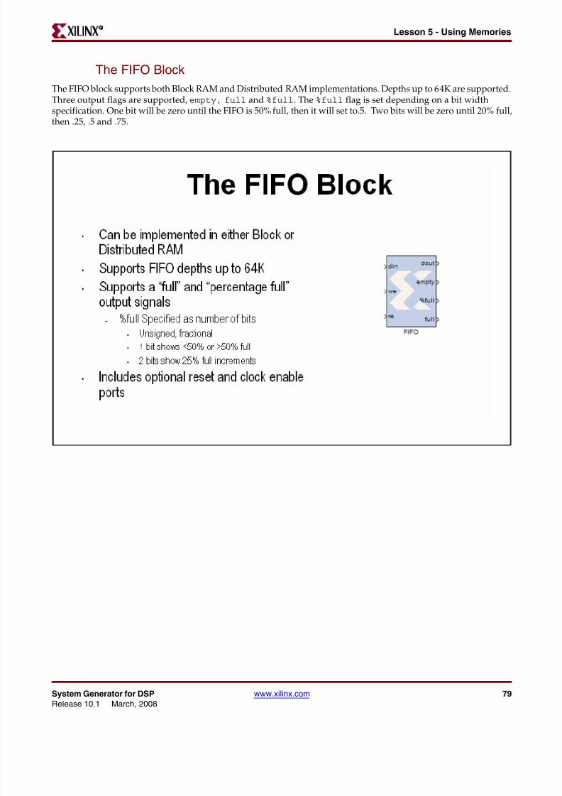
8112019 System Generator for DSP Getting Started
httpslidepdfcomreaderfullsystem-generator-for-dsp-getting-started 8093
80 wwwxilinxcom System Generator for DSPRelease 101 March 2008
Chapter 4 Getting Started R
Lab Exercise Using Memories
In this lab you will learn how to use a Xilinx ROM block to implement a LUT-basedoperation such as an Arcsin using Block RAM or Distributed RAM This provides anefficient implementation for trig and math functions with inputs that can be quantized to10 bits or less
The lab instructions and lab design are located in the System Generator software tree at thefollowing pathname
ltsysgen_treegtexamplesgetting_started_traininglab6
Lab Instructions
Lab Design
8112019 System Generator for DSP Getting Started
httpslidepdfcomreaderfullsystem-generator-for-dsp-getting-started 8193
System Generator for DSP wwwxilinxcom 81Release 101 March 2008
Lesson 6 - Designing FiltersR
Lesson 6 - Designing Filters
Introduction
Digital filters are a common DSP operation and especially well suited to implementation in FPGAs High-performance applications benefit greatly from parallel filters that can return a results on every clock cycle The
Virtex 5 device includes up to 550 parallel multipliers The FIR Compiler is designed to use these multipliers in themost efficient manner for creating commonly used FIR filters An alternative implementation is available calledldquodistributed arithmeticrdquo that creates FIR filters without using multipliers by employing a shift-add technique Thiscan be used for smaller devices when the available multipliers have been allocated to other functions
8112019 System Generator for DSP Getting Started
httpslidepdfcomreaderfullsystem-generator-for-dsp-getting-started 8293
82 wwwxilinxcom System Generator for DSPRelease 101 March 2008
Chapter 4 Getting Started R
The Virtex DSP48 Math Slice
The Virtextrade family introduces a high-performance arithmetic unit along with a multiplier the low-power DSP48slice The following figure is a detailed diagram of the DSP48 structure The DSP48 slice consists of four mainsections (1) IO registers (2) signed multiplier (3) three-input addersubtractor and (4) OPMODE multiplexers
8112019 System Generator for DSP Getting Started
httpslidepdfcomreaderfullsystem-generator-for-dsp-getting-started 8393
System Generator for DSP wwwxilinxcom 83Release 101 March 2008
Lesson 6 - Designing FiltersR
FIR Compiler Block
The Xilinx Fir Compiler v1_0 block implements a high speed MAC based FIR filter It accepts a stream of input dataand computes filtered output with a fixed delay based on the filter configuration The FIR Compiler supportsgeneration of resource shared or parallel FIR structures and polyphase decimation and interpolation structuresAlso supported is oversampling Coefficients are specified using MATLAB commands
8112019 System Generator for DSP Getting Started
httpslidepdfcomreaderfullsystem-generator-for-dsp-getting-started 8493
84 wwwxilinxcom System Generator for DSPRelease 101 March 2008
Chapter 4 Getting Started R
Creating Coefficients with FDATool
The Mathworks FDATool is a graphical filter design program that can be used to generate coefficients for the FIRCompiler block
8112019 System Generator for DSP Getting Started
httpslidepdfcomreaderfullsystem-generator-for-dsp-getting-started 8593
System Generator for DSP wwwxilinxcom 85Release 101 March 2008
Lesson 6 - Designing FiltersR
Using FDA Tool Coefficients
Once a suitable filter response has been designed you simply export the coefficients to the workspace using theFile gt Export command The workspace variable can then be referenced in the FIR Compiler properties editor
8112019 System Generator for DSP Getting Started
httpslidepdfcomreaderfullsystem-generator-for-dsp-getting-started 8693
86 wwwxilinxcom System Generator for DSPRelease 101 March 2008
Chapter 4 Getting Started R
Lab Exercise Designing Filters
In this lab you will be using the Filter Compiler block to generate optimized filters for theVirtex4 architecture
The lab instructions and lab design are located in the System Generator software tree at thefollowing pathname
ltsysgen_treegtexamplesgetting_started_traininglab7
Lab Instructions
Lab Design
8112019 System Generator for DSP Getting Started
httpslidepdfcomreaderfullsystem-generator-for-dsp-getting-started 8793
System Generator for DSP wwwxilinxcom 87Release 101 March 2008
Additional Examples and TutorialsR
Additional Examples and Tutorials
Numerous examples are used to illustrate System Generator features and functions in theSystem Generator documentaton These examples are found in the directory at pathnameltsysgen_treegtexamples and are listed in the table below In addition to theseexamples System Generator also includes demonstration models that can be run from the
demo page Enter the following command at the MATLAB promptdemo blocksets xilinx
Note If you are using the MATLAB help browser you can open and run the examples directly fromthis page To run an example click on the link MATLAB will change directories to the exampledirectory and open the example model
Black Box Examples
ChipScope Examples
Topic Description
Importing a VHDL
Module
A tutorial showing how to use the black box to import VHDL into a
System Generator design and how to use ModelSim to co-simulatethe VHDL module
Simulating SeveralBlack BoxesSimultaneously
Shows how black boxes can co-simulate simultaneously using onlyone ModelSim license
Dynamic Black Boxes A tutorial showing how to parameterize the black box
Importing a VerilogModule
A tutorial showing how to use the black box to import Verilog intoa System Generator design and how to use ModelSim to co-simulatethe Verilog module
Importing a Xilinx
Core GeneratorModule
A tutorial showing how to import a COREGEN module as a black
box
Topic Description
Using ChipScope ProAnalyzer for Real-Time HardwareDebugging
This tutorial demonstrates how to connect and use the Xilinx DebugTool called ChipScope Pro within Xilinx System Generator Theintegration of ChipScope Pro in the System Generator flow allowsreal-time debugging at system speed
8112019 System Generator for DSP Getting Started
httpslidepdfcomreaderfullsystem-generator-for-dsp-getting-started 8893
88 wwwxilinxcom System Generator for DSPRelease 101 March 2008
Chapter 4 Getting Started R
DSP Examples
Topic Description
DSP48 Block Simple example demonstrating the use of the DSP48 block with the
Constant block used to provide the DSP48 instruction
DSP48 Macro Block Simple example demonstrating how to use a DSP48 Macro block toimplement a Complex Multiplier
DSP48 Block
(35-Bit Multiplierusing DSP48 andConstant block)
This design demonstrates the use of the DSP48 and Constant blockin implementing 35 by 35-bit multipliers at different sample ratesThree multipliers implementations are shown at 1 2 and 4 clocksper sample
DSP48 Macro Block
(FIR filter using theDSP48 Macro block as
a multiply accumulatefunction)
This design demonstrates the use of the DSP48 Macro block inimplementing a 35 by 35 Multiplier
DSP48 Block
FIR filter examplesusing DSP48 block
This design demonstrates the use of the DSP48 and Constant blockin FIR filter implementation The design includes sets of parallelsemi-parallel and sequential FIR filter using Type 1 and Type 2architectures Each filter implements a 16-tap dsp48-based FIRfilters
DSP48 DesignTechniques
(DSP48-baseddynamic shifter)
This design demonstrates the use of the DSP48 block inimplementing a 35-bit signed right shift using 2 DSP48s
DSP48 DesignTechniques
(Synthesizable FIRfilter for Virtex4)
This design demonstrates how to use System Generator toimplement a synthesizable FIR filter which maps efficiently to theVirtex4 architecture
DSP48 Macro Block
(FIR filter using theDSP48 Macro block asa multiply accumulatefunction)
This design demonstrates the use of the DSP48 Macro block whenimplementing a sequential FIR filter
MAC FIR filter This design example implements a 43 tap FIR Filter with a MACengine and a Dual Port Ram used for data and coefficient storage
Complex FIR filter This example demonstrates a complex FIR filter built out of blocksfrom the System Generator and Simulink library
8112019 System Generator for DSP Getting Started
httpslidepdfcomreaderfullsystem-generator-for-dsp-getting-started 8993
System Generator for DSP wwwxilinxcom 89Release 101 March 2008
Additional Examples and TutorialsR
M-Code Examples
Processor Examples
Topic Description
Simple Selector This example shows how to implement a function that returns the
maximum value of its inputsSimple ArithmeticOperations
This example shows how to implement simple arithmeticoperations
Complex Multiplierwith Latency
This example shows how to build a complex multiplier with latency
Shift Operations This example shows how to implement shift operations
Passing Parametersinto the MCode Block
This example shows how to pass parameters into a MCode block
Optional Input Ports This example shows how to implement optional input ports on an
MCode blockFinite State Machines This example shows how to implement a finite state machine
ParameterizableAccumulator
This example shows how to build a parameterizable accumulator
FIR Blocks andVerification
This example shows how to model FIR blocks and how to do systemverification
RPN Calculator This example shows how to model a RPN calculator ndash a stackmachine
Example of disp
function
This example shows how to use the disp function
Topic Description
Designing andExporting MicroBlazeProcessor Peripherals
Demonstrates how to export a design from System Generator intoXilinx Platform Studio (EDK) by showing how to design aperipheral (pcore) for a MicroBlaze processor An RGB to gray-scalecolor space converter is created and generated into a pcore using theExport to EDK compilation target
8112019 System Generator for DSP Getting Started
httpslidepdfcomreaderfullsystem-generator-for-dsp-getting-started 9093
90 wwwxilinxcom System Generator for DSPRelease 101 March 2008
Chapter 4 Getting Started R
Shared Memory Examples
Tutorial Example -Designing andSimulatingMicroBlaze ProcessorSystems
Demonstrates how to import a MicroBlaze processor created usingXilinx Platform Studio into System Generator A DSP48 block isused as a co-processor to the MicroBlaze
Designing PicoBlazeMicrocontrollerApplications
Demonstrates how to implement a PicoBlaze program in SystemGenerator The example programs the PicoBlaze to alter the outputfrequency of a Direct Digital Synthesizer (DDS) during an interrupt
Topic Description
Topic Description
Simulation across
various models
Illustrates shared memories communicating across Simulink
models
Host PC SharedMemory access
Developer studio project to communicate with a shared memory
High Speed VideoProcessing usingHardware Co-simulation
Discussion of a high-speed co-simulation buffering interfacefollowed by an example in which the interface is used to supportreal-time processing of a video stream using a 5x5 filter kernel
High speed IOBuffering
Illustrates high speed Shared Memory IO Buffering Interface forHardware Co-simulation
SharedMemory
(Mex-functioninterface)
Illustrates the use of a mex-function as an interface to a sharedmemory
Generating MultipleCycle-True Islands forDistinct Clocks
An example using two asynchronous clocks
Shared Memory ToFIFO To Register ToRegister FromRegister
Demonstrates use of shared memories FIFOs and registers to passinformation
Frame-BasedAcceleration usingHardware Co-
Simulation
Explains how to use frame or vector-based transfers to furtheraccelerate simulations using FPGA hardware co-simulation
8112019 System Generator for DSP Getting Started
httpslidepdfcomreaderfullsystem-generator-for-dsp-getting-started 9193
System Generator for DSP wwwxilinxcom 91Release 101 March 2008
Additional Examples and TutorialsR
Timing Analysis Examples
Miscellaneous Examples
Topic Description
Timing Analysis
Tutorial
Explains how to use the System Generator Timing Analysis tool to
meet timing requirements of System Generator designs Alsotouches on techniques that may be used when a design does notmeet timing
Topic Description
Importing a SystemGenerator Design intoa Bigger System
Discusses how to take the VHDL netlist from a System Generatordesign and synthesize it in order to embed it into a larger designAlso shows how VHDL created by System Generator can beincorporated into simulation model of the overall system
ConfigurableSubsystems andSystem Generator
Illustrates the use of Configurable Subsystems for Simulation andGeneration
Integrator This example uses an integrator to illustrate error analysiscapability
Block RAM-BasedState Machines
Demonstrates use of Mealy State Machine block from the referencelibrary
8112019 System Generator for DSP Getting Started
httpslidepdfcomreaderfullsystem-generator-for-dsp-getting-started 9293
92 wwwxilinxcom System Generator for DSPRelease 101 March 2008
Chapter 4 Getting Started R
System Generator Demos
System Generator for DSP provides the capability to model and implement high-performance DSP systems in field- programmable gate arrays (FPGAs) using SimulinkThe Xilinx Blockset contains bit and cycle-true models of arithmetic and logic functionsmemories and DSP functions for digital filtering spectral analysis and digitalcommunications System Generator converts a Simulink model of Xilinx blocks into anefficient hardware implementation that combines synthesizable VHDL and intellectualproperty blocks that have been hand-crafted to run efficiently in FPGAs
Included with the tool are numerous demonstration designs that highlight key featuresand tool capabilities as well as general good design practices using real-world designapplications These designs may be accessed from the System Generator demo page Enterthe following command at the MATLAB prompt
demo blocksets xilinx
8112019 System Generator for DSP Getting Started
httpslidepdfcomreaderfullsystem-generator-for-dsp-getting-started 9393
AAsynchronous Software Drivers
for FSLs 25
CCompatibility
MATLAB 24 29 34 36
ModelSim 24 29 34 36
Synplify Pro 24 29 34 36
Compiling
Xilinx HDL Libraries 21
Configuring
the Sysgen cache 21
Custom Bus Interfacesfor exported pcore 26
DDownloading
System Generator 19
EExport pcore
enable Custom Bus Interfaces 26
FFast Simplex Link
asynchronous software drivers for 25
H
MMATLAB 24 29 34 36
Memory Stitching 31ModelSim 24 29 34 36
PPcore
export as under development 26
SShared Memory Stitching 31
Software Drivers
asynchronous for FSLs 25System Generator
Cache 21
changing versions 21
displaying versions 21
downloading the software 19
ISE Design Suite Installer 20
System Generator Utilities
xlUpdateModel 37
U
Underdevelopmentexport pcore as 26
XXilinx HDL Libraries
compiling 21
xlUpdateModel 37
Index
8112019 System Generator for DSP Getting Started
httpslidepdfcomreaderfullsystem-generator-for-dsp-getting-started 8193
System Generator for DSP wwwxilinxcom 81Release 101 March 2008
Lesson 6 - Designing FiltersR
Lesson 6 - Designing Filters
Introduction
Digital filters are a common DSP operation and especially well suited to implementation in FPGAs High-performance applications benefit greatly from parallel filters that can return a results on every clock cycle The
Virtex 5 device includes up to 550 parallel multipliers The FIR Compiler is designed to use these multipliers in themost efficient manner for creating commonly used FIR filters An alternative implementation is available calledldquodistributed arithmeticrdquo that creates FIR filters without using multipliers by employing a shift-add technique Thiscan be used for smaller devices when the available multipliers have been allocated to other functions
8112019 System Generator for DSP Getting Started
httpslidepdfcomreaderfullsystem-generator-for-dsp-getting-started 8293
82 wwwxilinxcom System Generator for DSPRelease 101 March 2008
Chapter 4 Getting Started R
The Virtex DSP48 Math Slice
The Virtextrade family introduces a high-performance arithmetic unit along with a multiplier the low-power DSP48slice The following figure is a detailed diagram of the DSP48 structure The DSP48 slice consists of four mainsections (1) IO registers (2) signed multiplier (3) three-input addersubtractor and (4) OPMODE multiplexers
8112019 System Generator for DSP Getting Started
httpslidepdfcomreaderfullsystem-generator-for-dsp-getting-started 8393
System Generator for DSP wwwxilinxcom 83Release 101 March 2008
Lesson 6 - Designing FiltersR
FIR Compiler Block
The Xilinx Fir Compiler v1_0 block implements a high speed MAC based FIR filter It accepts a stream of input dataand computes filtered output with a fixed delay based on the filter configuration The FIR Compiler supportsgeneration of resource shared or parallel FIR structures and polyphase decimation and interpolation structuresAlso supported is oversampling Coefficients are specified using MATLAB commands
8112019 System Generator for DSP Getting Started
httpslidepdfcomreaderfullsystem-generator-for-dsp-getting-started 8493
84 wwwxilinxcom System Generator for DSPRelease 101 March 2008
Chapter 4 Getting Started R
Creating Coefficients with FDATool
The Mathworks FDATool is a graphical filter design program that can be used to generate coefficients for the FIRCompiler block
8112019 System Generator for DSP Getting Started
httpslidepdfcomreaderfullsystem-generator-for-dsp-getting-started 8593
System Generator for DSP wwwxilinxcom 85Release 101 March 2008
Lesson 6 - Designing FiltersR
Using FDA Tool Coefficients
Once a suitable filter response has been designed you simply export the coefficients to the workspace using theFile gt Export command The workspace variable can then be referenced in the FIR Compiler properties editor
8112019 System Generator for DSP Getting Started
httpslidepdfcomreaderfullsystem-generator-for-dsp-getting-started 8693
86 wwwxilinxcom System Generator for DSPRelease 101 March 2008
Chapter 4 Getting Started R
Lab Exercise Designing Filters
In this lab you will be using the Filter Compiler block to generate optimized filters for theVirtex4 architecture
The lab instructions and lab design are located in the System Generator software tree at thefollowing pathname
ltsysgen_treegtexamplesgetting_started_traininglab7
Lab Instructions
Lab Design
8112019 System Generator for DSP Getting Started
httpslidepdfcomreaderfullsystem-generator-for-dsp-getting-started 8793
System Generator for DSP wwwxilinxcom 87Release 101 March 2008
Additional Examples and TutorialsR
Additional Examples and Tutorials
Numerous examples are used to illustrate System Generator features and functions in theSystem Generator documentaton These examples are found in the directory at pathnameltsysgen_treegtexamples and are listed in the table below In addition to theseexamples System Generator also includes demonstration models that can be run from the
demo page Enter the following command at the MATLAB promptdemo blocksets xilinx
Note If you are using the MATLAB help browser you can open and run the examples directly fromthis page To run an example click on the link MATLAB will change directories to the exampledirectory and open the example model
Black Box Examples
ChipScope Examples
Topic Description
Importing a VHDL
Module
A tutorial showing how to use the black box to import VHDL into a
System Generator design and how to use ModelSim to co-simulatethe VHDL module
Simulating SeveralBlack BoxesSimultaneously
Shows how black boxes can co-simulate simultaneously using onlyone ModelSim license
Dynamic Black Boxes A tutorial showing how to parameterize the black box
Importing a VerilogModule
A tutorial showing how to use the black box to import Verilog intoa System Generator design and how to use ModelSim to co-simulatethe Verilog module
Importing a Xilinx
Core GeneratorModule
A tutorial showing how to import a COREGEN module as a black
box
Topic Description
Using ChipScope ProAnalyzer for Real-Time HardwareDebugging
This tutorial demonstrates how to connect and use the Xilinx DebugTool called ChipScope Pro within Xilinx System Generator Theintegration of ChipScope Pro in the System Generator flow allowsreal-time debugging at system speed
8112019 System Generator for DSP Getting Started
httpslidepdfcomreaderfullsystem-generator-for-dsp-getting-started 8893
88 wwwxilinxcom System Generator for DSPRelease 101 March 2008
Chapter 4 Getting Started R
DSP Examples
Topic Description
DSP48 Block Simple example demonstrating the use of the DSP48 block with the
Constant block used to provide the DSP48 instruction
DSP48 Macro Block Simple example demonstrating how to use a DSP48 Macro block toimplement a Complex Multiplier
DSP48 Block
(35-Bit Multiplierusing DSP48 andConstant block)
This design demonstrates the use of the DSP48 and Constant blockin implementing 35 by 35-bit multipliers at different sample ratesThree multipliers implementations are shown at 1 2 and 4 clocksper sample
DSP48 Macro Block
(FIR filter using theDSP48 Macro block as
a multiply accumulatefunction)
This design demonstrates the use of the DSP48 Macro block inimplementing a 35 by 35 Multiplier
DSP48 Block
FIR filter examplesusing DSP48 block
This design demonstrates the use of the DSP48 and Constant blockin FIR filter implementation The design includes sets of parallelsemi-parallel and sequential FIR filter using Type 1 and Type 2architectures Each filter implements a 16-tap dsp48-based FIRfilters
DSP48 DesignTechniques
(DSP48-baseddynamic shifter)
This design demonstrates the use of the DSP48 block inimplementing a 35-bit signed right shift using 2 DSP48s
DSP48 DesignTechniques
(Synthesizable FIRfilter for Virtex4)
This design demonstrates how to use System Generator toimplement a synthesizable FIR filter which maps efficiently to theVirtex4 architecture
DSP48 Macro Block
(FIR filter using theDSP48 Macro block asa multiply accumulatefunction)
This design demonstrates the use of the DSP48 Macro block whenimplementing a sequential FIR filter
MAC FIR filter This design example implements a 43 tap FIR Filter with a MACengine and a Dual Port Ram used for data and coefficient storage
Complex FIR filter This example demonstrates a complex FIR filter built out of blocksfrom the System Generator and Simulink library
8112019 System Generator for DSP Getting Started
httpslidepdfcomreaderfullsystem-generator-for-dsp-getting-started 8993
System Generator for DSP wwwxilinxcom 89Release 101 March 2008
Additional Examples and TutorialsR
M-Code Examples
Processor Examples
Topic Description
Simple Selector This example shows how to implement a function that returns the
maximum value of its inputsSimple ArithmeticOperations
This example shows how to implement simple arithmeticoperations
Complex Multiplierwith Latency
This example shows how to build a complex multiplier with latency
Shift Operations This example shows how to implement shift operations
Passing Parametersinto the MCode Block
This example shows how to pass parameters into a MCode block
Optional Input Ports This example shows how to implement optional input ports on an
MCode blockFinite State Machines This example shows how to implement a finite state machine
ParameterizableAccumulator
This example shows how to build a parameterizable accumulator
FIR Blocks andVerification
This example shows how to model FIR blocks and how to do systemverification
RPN Calculator This example shows how to model a RPN calculator ndash a stackmachine
Example of disp
function
This example shows how to use the disp function
Topic Description
Designing andExporting MicroBlazeProcessor Peripherals
Demonstrates how to export a design from System Generator intoXilinx Platform Studio (EDK) by showing how to design aperipheral (pcore) for a MicroBlaze processor An RGB to gray-scalecolor space converter is created and generated into a pcore using theExport to EDK compilation target
8112019 System Generator for DSP Getting Started
httpslidepdfcomreaderfullsystem-generator-for-dsp-getting-started 9093
90 wwwxilinxcom System Generator for DSPRelease 101 March 2008
Chapter 4 Getting Started R
Shared Memory Examples
Tutorial Example -Designing andSimulatingMicroBlaze ProcessorSystems
Demonstrates how to import a MicroBlaze processor created usingXilinx Platform Studio into System Generator A DSP48 block isused as a co-processor to the MicroBlaze
Designing PicoBlazeMicrocontrollerApplications
Demonstrates how to implement a PicoBlaze program in SystemGenerator The example programs the PicoBlaze to alter the outputfrequency of a Direct Digital Synthesizer (DDS) during an interrupt
Topic Description
Topic Description
Simulation across
various models
Illustrates shared memories communicating across Simulink
models
Host PC SharedMemory access
Developer studio project to communicate with a shared memory
High Speed VideoProcessing usingHardware Co-simulation
Discussion of a high-speed co-simulation buffering interfacefollowed by an example in which the interface is used to supportreal-time processing of a video stream using a 5x5 filter kernel
High speed IOBuffering
Illustrates high speed Shared Memory IO Buffering Interface forHardware Co-simulation
SharedMemory
(Mex-functioninterface)
Illustrates the use of a mex-function as an interface to a sharedmemory
Generating MultipleCycle-True Islands forDistinct Clocks
An example using two asynchronous clocks
Shared Memory ToFIFO To Register ToRegister FromRegister
Demonstrates use of shared memories FIFOs and registers to passinformation
Frame-BasedAcceleration usingHardware Co-
Simulation
Explains how to use frame or vector-based transfers to furtheraccelerate simulations using FPGA hardware co-simulation
8112019 System Generator for DSP Getting Started
httpslidepdfcomreaderfullsystem-generator-for-dsp-getting-started 9193
System Generator for DSP wwwxilinxcom 91Release 101 March 2008
Additional Examples and TutorialsR
Timing Analysis Examples
Miscellaneous Examples
Topic Description
Timing Analysis
Tutorial
Explains how to use the System Generator Timing Analysis tool to
meet timing requirements of System Generator designs Alsotouches on techniques that may be used when a design does notmeet timing
Topic Description
Importing a SystemGenerator Design intoa Bigger System
Discusses how to take the VHDL netlist from a System Generatordesign and synthesize it in order to embed it into a larger designAlso shows how VHDL created by System Generator can beincorporated into simulation model of the overall system
ConfigurableSubsystems andSystem Generator
Illustrates the use of Configurable Subsystems for Simulation andGeneration
Integrator This example uses an integrator to illustrate error analysiscapability
Block RAM-BasedState Machines
Demonstrates use of Mealy State Machine block from the referencelibrary
8112019 System Generator for DSP Getting Started
httpslidepdfcomreaderfullsystem-generator-for-dsp-getting-started 9293
92 wwwxilinxcom System Generator for DSPRelease 101 March 2008
Chapter 4 Getting Started R
System Generator Demos
System Generator for DSP provides the capability to model and implement high-performance DSP systems in field- programmable gate arrays (FPGAs) using SimulinkThe Xilinx Blockset contains bit and cycle-true models of arithmetic and logic functionsmemories and DSP functions for digital filtering spectral analysis and digitalcommunications System Generator converts a Simulink model of Xilinx blocks into anefficient hardware implementation that combines synthesizable VHDL and intellectualproperty blocks that have been hand-crafted to run efficiently in FPGAs
Included with the tool are numerous demonstration designs that highlight key featuresand tool capabilities as well as general good design practices using real-world designapplications These designs may be accessed from the System Generator demo page Enterthe following command at the MATLAB prompt
demo blocksets xilinx
8112019 System Generator for DSP Getting Started
httpslidepdfcomreaderfullsystem-generator-for-dsp-getting-started 9393
AAsynchronous Software Drivers
for FSLs 25
CCompatibility
MATLAB 24 29 34 36
ModelSim 24 29 34 36
Synplify Pro 24 29 34 36
Compiling
Xilinx HDL Libraries 21
Configuring
the Sysgen cache 21
Custom Bus Interfacesfor exported pcore 26
DDownloading
System Generator 19
EExport pcore
enable Custom Bus Interfaces 26
FFast Simplex Link
asynchronous software drivers for 25
H
MMATLAB 24 29 34 36
Memory Stitching 31ModelSim 24 29 34 36
PPcore
export as under development 26
SShared Memory Stitching 31
Software Drivers
asynchronous for FSLs 25System Generator
Cache 21
changing versions 21
displaying versions 21
downloading the software 19
ISE Design Suite Installer 20
System Generator Utilities
xlUpdateModel 37
U
Underdevelopmentexport pcore as 26
XXilinx HDL Libraries
compiling 21
xlUpdateModel 37
Index
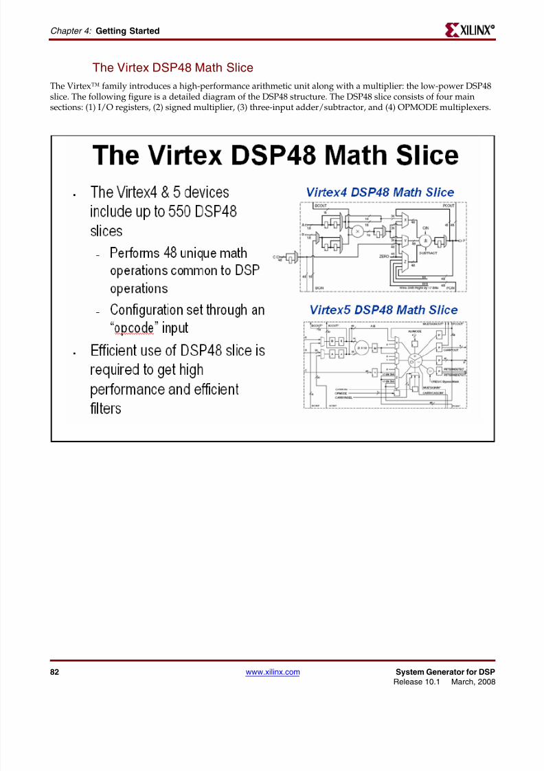
8112019 System Generator for DSP Getting Started
httpslidepdfcomreaderfullsystem-generator-for-dsp-getting-started 8693
86 wwwxilinxcom System Generator for DSPRelease 101 March 2008
Chapter 4 Getting Started R
Lab Exercise Designing Filters
In this lab you will be using the Filter Compiler block to generate optimized filters for theVirtex4 architecture
The lab instructions and lab design are located in the System Generator software tree at thefollowing pathname
ltsysgen_treegtexamplesgetting_started_traininglab7
Lab Instructions
Lab Design
8112019 System Generator for DSP Getting Started
httpslidepdfcomreaderfullsystem-generator-for-dsp-getting-started 8793
System Generator for DSP wwwxilinxcom 87Release 101 March 2008
Additional Examples and TutorialsR
Additional Examples and Tutorials
Numerous examples are used to illustrate System Generator features and functions in theSystem Generator documentaton These examples are found in the directory at pathnameltsysgen_treegtexamples and are listed in the table below In addition to theseexamples System Generator also includes demonstration models that can be run from the
demo page Enter the following command at the MATLAB promptdemo blocksets xilinx
Note If you are using the MATLAB help browser you can open and run the examples directly fromthis page To run an example click on the link MATLAB will change directories to the exampledirectory and open the example model
Black Box Examples
ChipScope Examples
Topic Description
Importing a VHDL
Module
A tutorial showing how to use the black box to import VHDL into a
System Generator design and how to use ModelSim to co-simulatethe VHDL module
Simulating SeveralBlack BoxesSimultaneously
Shows how black boxes can co-simulate simultaneously using onlyone ModelSim license
Dynamic Black Boxes A tutorial showing how to parameterize the black box
Importing a VerilogModule
A tutorial showing how to use the black box to import Verilog intoa System Generator design and how to use ModelSim to co-simulatethe Verilog module
Importing a Xilinx
Core GeneratorModule
A tutorial showing how to import a COREGEN module as a black
box
Topic Description
Using ChipScope ProAnalyzer for Real-Time HardwareDebugging
This tutorial demonstrates how to connect and use the Xilinx DebugTool called ChipScope Pro within Xilinx System Generator Theintegration of ChipScope Pro in the System Generator flow allowsreal-time debugging at system speed
8112019 System Generator for DSP Getting Started
httpslidepdfcomreaderfullsystem-generator-for-dsp-getting-started 8893
88 wwwxilinxcom System Generator for DSPRelease 101 March 2008
Chapter 4 Getting Started R
DSP Examples
Topic Description
DSP48 Block Simple example demonstrating the use of the DSP48 block with the
Constant block used to provide the DSP48 instruction
DSP48 Macro Block Simple example demonstrating how to use a DSP48 Macro block toimplement a Complex Multiplier
DSP48 Block
(35-Bit Multiplierusing DSP48 andConstant block)
This design demonstrates the use of the DSP48 and Constant blockin implementing 35 by 35-bit multipliers at different sample ratesThree multipliers implementations are shown at 1 2 and 4 clocksper sample
DSP48 Macro Block
(FIR filter using theDSP48 Macro block as
a multiply accumulatefunction)
This design demonstrates the use of the DSP48 Macro block inimplementing a 35 by 35 Multiplier
DSP48 Block
FIR filter examplesusing DSP48 block
This design demonstrates the use of the DSP48 and Constant blockin FIR filter implementation The design includes sets of parallelsemi-parallel and sequential FIR filter using Type 1 and Type 2architectures Each filter implements a 16-tap dsp48-based FIRfilters
DSP48 DesignTechniques
(DSP48-baseddynamic shifter)
This design demonstrates the use of the DSP48 block inimplementing a 35-bit signed right shift using 2 DSP48s
DSP48 DesignTechniques
(Synthesizable FIRfilter for Virtex4)
This design demonstrates how to use System Generator toimplement a synthesizable FIR filter which maps efficiently to theVirtex4 architecture
DSP48 Macro Block
(FIR filter using theDSP48 Macro block asa multiply accumulatefunction)
This design demonstrates the use of the DSP48 Macro block whenimplementing a sequential FIR filter
MAC FIR filter This design example implements a 43 tap FIR Filter with a MACengine and a Dual Port Ram used for data and coefficient storage
Complex FIR filter This example demonstrates a complex FIR filter built out of blocksfrom the System Generator and Simulink library
8112019 System Generator for DSP Getting Started
httpslidepdfcomreaderfullsystem-generator-for-dsp-getting-started 8993
System Generator for DSP wwwxilinxcom 89Release 101 March 2008
Additional Examples and TutorialsR
M-Code Examples
Processor Examples
Topic Description
Simple Selector This example shows how to implement a function that returns the
maximum value of its inputsSimple ArithmeticOperations
This example shows how to implement simple arithmeticoperations
Complex Multiplierwith Latency
This example shows how to build a complex multiplier with latency
Shift Operations This example shows how to implement shift operations
Passing Parametersinto the MCode Block
This example shows how to pass parameters into a MCode block
Optional Input Ports This example shows how to implement optional input ports on an
MCode blockFinite State Machines This example shows how to implement a finite state machine
ParameterizableAccumulator
This example shows how to build a parameterizable accumulator
FIR Blocks andVerification
This example shows how to model FIR blocks and how to do systemverification
RPN Calculator This example shows how to model a RPN calculator ndash a stackmachine
Example of disp
function
This example shows how to use the disp function
Topic Description
Designing andExporting MicroBlazeProcessor Peripherals
Demonstrates how to export a design from System Generator intoXilinx Platform Studio (EDK) by showing how to design aperipheral (pcore) for a MicroBlaze processor An RGB to gray-scalecolor space converter is created and generated into a pcore using theExport to EDK compilation target
8112019 System Generator for DSP Getting Started
httpslidepdfcomreaderfullsystem-generator-for-dsp-getting-started 9093
90 wwwxilinxcom System Generator for DSPRelease 101 March 2008
Chapter 4 Getting Started R
Shared Memory Examples
Tutorial Example -Designing andSimulatingMicroBlaze ProcessorSystems
Demonstrates how to import a MicroBlaze processor created usingXilinx Platform Studio into System Generator A DSP48 block isused as a co-processor to the MicroBlaze
Designing PicoBlazeMicrocontrollerApplications
Demonstrates how to implement a PicoBlaze program in SystemGenerator The example programs the PicoBlaze to alter the outputfrequency of a Direct Digital Synthesizer (DDS) during an interrupt
Topic Description
Topic Description
Simulation across
various models
Illustrates shared memories communicating across Simulink
models
Host PC SharedMemory access
Developer studio project to communicate with a shared memory
High Speed VideoProcessing usingHardware Co-simulation
Discussion of a high-speed co-simulation buffering interfacefollowed by an example in which the interface is used to supportreal-time processing of a video stream using a 5x5 filter kernel
High speed IOBuffering
Illustrates high speed Shared Memory IO Buffering Interface forHardware Co-simulation
SharedMemory
(Mex-functioninterface)
Illustrates the use of a mex-function as an interface to a sharedmemory
Generating MultipleCycle-True Islands forDistinct Clocks
An example using two asynchronous clocks
Shared Memory ToFIFO To Register ToRegister FromRegister
Demonstrates use of shared memories FIFOs and registers to passinformation
Frame-BasedAcceleration usingHardware Co-
Simulation
Explains how to use frame or vector-based transfers to furtheraccelerate simulations using FPGA hardware co-simulation
8112019 System Generator for DSP Getting Started
httpslidepdfcomreaderfullsystem-generator-for-dsp-getting-started 9193
System Generator for DSP wwwxilinxcom 91Release 101 March 2008
Additional Examples and TutorialsR
Timing Analysis Examples
Miscellaneous Examples
Topic Description
Timing Analysis
Tutorial
Explains how to use the System Generator Timing Analysis tool to
meet timing requirements of System Generator designs Alsotouches on techniques that may be used when a design does notmeet timing
Topic Description
Importing a SystemGenerator Design intoa Bigger System
Discusses how to take the VHDL netlist from a System Generatordesign and synthesize it in order to embed it into a larger designAlso shows how VHDL created by System Generator can beincorporated into simulation model of the overall system
ConfigurableSubsystems andSystem Generator
Illustrates the use of Configurable Subsystems for Simulation andGeneration
Integrator This example uses an integrator to illustrate error analysiscapability
Block RAM-BasedState Machines
Demonstrates use of Mealy State Machine block from the referencelibrary
8112019 System Generator for DSP Getting Started
httpslidepdfcomreaderfullsystem-generator-for-dsp-getting-started 9293
92 wwwxilinxcom System Generator for DSPRelease 101 March 2008
Chapter 4 Getting Started R
System Generator Demos
System Generator for DSP provides the capability to model and implement high-performance DSP systems in field- programmable gate arrays (FPGAs) using SimulinkThe Xilinx Blockset contains bit and cycle-true models of arithmetic and logic functionsmemories and DSP functions for digital filtering spectral analysis and digitalcommunications System Generator converts a Simulink model of Xilinx blocks into anefficient hardware implementation that combines synthesizable VHDL and intellectualproperty blocks that have been hand-crafted to run efficiently in FPGAs
Included with the tool are numerous demonstration designs that highlight key featuresand tool capabilities as well as general good design practices using real-world designapplications These designs may be accessed from the System Generator demo page Enterthe following command at the MATLAB prompt
demo blocksets xilinx
8112019 System Generator for DSP Getting Started
httpslidepdfcomreaderfullsystem-generator-for-dsp-getting-started 9393
AAsynchronous Software Drivers
for FSLs 25
CCompatibility
MATLAB 24 29 34 36
ModelSim 24 29 34 36
Synplify Pro 24 29 34 36
Compiling
Xilinx HDL Libraries 21
Configuring
the Sysgen cache 21
Custom Bus Interfacesfor exported pcore 26
DDownloading
System Generator 19
EExport pcore
enable Custom Bus Interfaces 26
FFast Simplex Link
asynchronous software drivers for 25
H
MMATLAB 24 29 34 36
Memory Stitching 31ModelSim 24 29 34 36
PPcore
export as under development 26
SShared Memory Stitching 31
Software Drivers
asynchronous for FSLs 25System Generator
Cache 21
changing versions 21
displaying versions 21
downloading the software 19
ISE Design Suite Installer 20
System Generator Utilities
xlUpdateModel 37
U
Underdevelopmentexport pcore as 26
XXilinx HDL Libraries
compiling 21
xlUpdateModel 37
Index
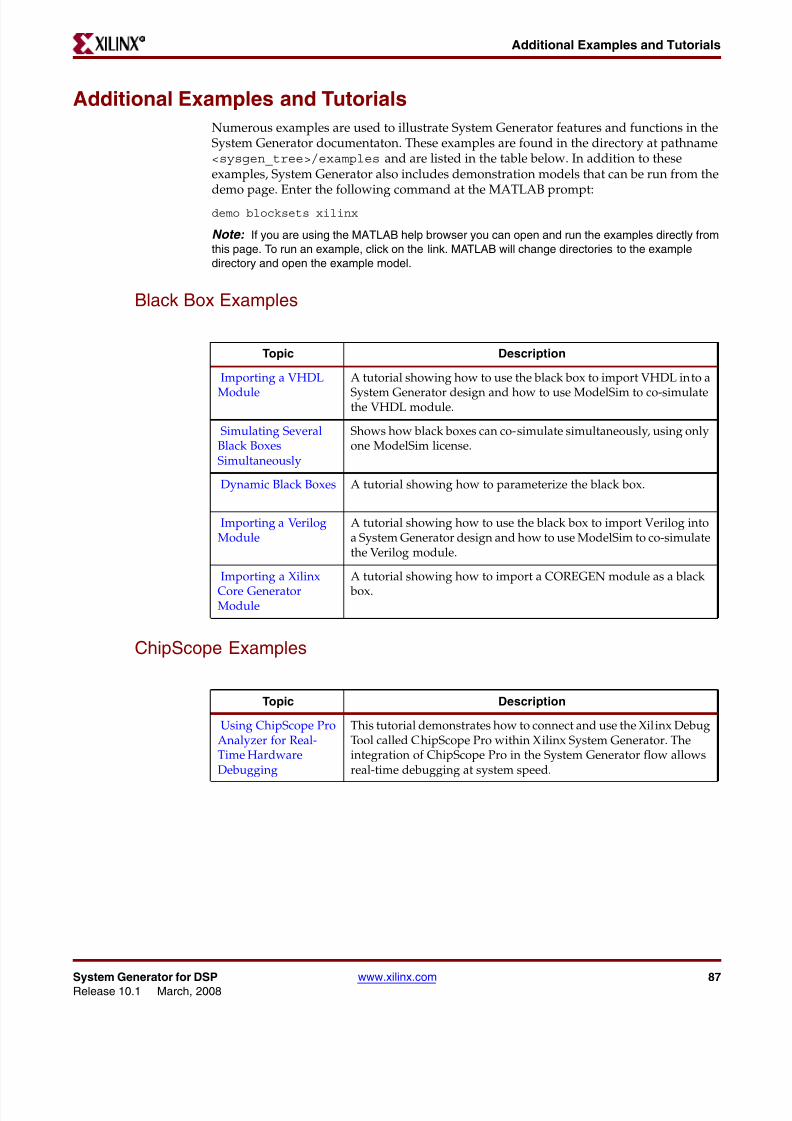
8112019 System Generator for DSP Getting Started
httpslidepdfcomreaderfullsystem-generator-for-dsp-getting-started 8793
System Generator for DSP wwwxilinxcom 87Release 101 March 2008
Additional Examples and TutorialsR
Additional Examples and Tutorials
Numerous examples are used to illustrate System Generator features and functions in theSystem Generator documentaton These examples are found in the directory at pathnameltsysgen_treegtexamples and are listed in the table below In addition to theseexamples System Generator also includes demonstration models that can be run from the
demo page Enter the following command at the MATLAB promptdemo blocksets xilinx
Note If you are using the MATLAB help browser you can open and run the examples directly fromthis page To run an example click on the link MATLAB will change directories to the exampledirectory and open the example model
Black Box Examples
ChipScope Examples
Topic Description
Importing a VHDL
Module
A tutorial showing how to use the black box to import VHDL into a
System Generator design and how to use ModelSim to co-simulatethe VHDL module
Simulating SeveralBlack BoxesSimultaneously
Shows how black boxes can co-simulate simultaneously using onlyone ModelSim license
Dynamic Black Boxes A tutorial showing how to parameterize the black box
Importing a VerilogModule
A tutorial showing how to use the black box to import Verilog intoa System Generator design and how to use ModelSim to co-simulatethe Verilog module
Importing a Xilinx
Core GeneratorModule
A tutorial showing how to import a COREGEN module as a black
box
Topic Description
Using ChipScope ProAnalyzer for Real-Time HardwareDebugging
This tutorial demonstrates how to connect and use the Xilinx DebugTool called ChipScope Pro within Xilinx System Generator Theintegration of ChipScope Pro in the System Generator flow allowsreal-time debugging at system speed
8112019 System Generator for DSP Getting Started
httpslidepdfcomreaderfullsystem-generator-for-dsp-getting-started 8893
88 wwwxilinxcom System Generator for DSPRelease 101 March 2008
Chapter 4 Getting Started R
DSP Examples
Topic Description
DSP48 Block Simple example demonstrating the use of the DSP48 block with the
Constant block used to provide the DSP48 instruction
DSP48 Macro Block Simple example demonstrating how to use a DSP48 Macro block toimplement a Complex Multiplier
DSP48 Block
(35-Bit Multiplierusing DSP48 andConstant block)
This design demonstrates the use of the DSP48 and Constant blockin implementing 35 by 35-bit multipliers at different sample ratesThree multipliers implementations are shown at 1 2 and 4 clocksper sample
DSP48 Macro Block
(FIR filter using theDSP48 Macro block as
a multiply accumulatefunction)
This design demonstrates the use of the DSP48 Macro block inimplementing a 35 by 35 Multiplier
DSP48 Block
FIR filter examplesusing DSP48 block
This design demonstrates the use of the DSP48 and Constant blockin FIR filter implementation The design includes sets of parallelsemi-parallel and sequential FIR filter using Type 1 and Type 2architectures Each filter implements a 16-tap dsp48-based FIRfilters
DSP48 DesignTechniques
(DSP48-baseddynamic shifter)
This design demonstrates the use of the DSP48 block inimplementing a 35-bit signed right shift using 2 DSP48s
DSP48 DesignTechniques
(Synthesizable FIRfilter for Virtex4)
This design demonstrates how to use System Generator toimplement a synthesizable FIR filter which maps efficiently to theVirtex4 architecture
DSP48 Macro Block
(FIR filter using theDSP48 Macro block asa multiply accumulatefunction)
This design demonstrates the use of the DSP48 Macro block whenimplementing a sequential FIR filter
MAC FIR filter This design example implements a 43 tap FIR Filter with a MACengine and a Dual Port Ram used for data and coefficient storage
Complex FIR filter This example demonstrates a complex FIR filter built out of blocksfrom the System Generator and Simulink library
8112019 System Generator for DSP Getting Started
httpslidepdfcomreaderfullsystem-generator-for-dsp-getting-started 8993
System Generator for DSP wwwxilinxcom 89Release 101 March 2008
Additional Examples and TutorialsR
M-Code Examples
Processor Examples
Topic Description
Simple Selector This example shows how to implement a function that returns the
maximum value of its inputsSimple ArithmeticOperations
This example shows how to implement simple arithmeticoperations
Complex Multiplierwith Latency
This example shows how to build a complex multiplier with latency
Shift Operations This example shows how to implement shift operations
Passing Parametersinto the MCode Block
This example shows how to pass parameters into a MCode block
Optional Input Ports This example shows how to implement optional input ports on an
MCode blockFinite State Machines This example shows how to implement a finite state machine
ParameterizableAccumulator
This example shows how to build a parameterizable accumulator
FIR Blocks andVerification
This example shows how to model FIR blocks and how to do systemverification
RPN Calculator This example shows how to model a RPN calculator ndash a stackmachine
Example of disp
function
This example shows how to use the disp function
Topic Description
Designing andExporting MicroBlazeProcessor Peripherals
Demonstrates how to export a design from System Generator intoXilinx Platform Studio (EDK) by showing how to design aperipheral (pcore) for a MicroBlaze processor An RGB to gray-scalecolor space converter is created and generated into a pcore using theExport to EDK compilation target
8112019 System Generator for DSP Getting Started
httpslidepdfcomreaderfullsystem-generator-for-dsp-getting-started 9093
90 wwwxilinxcom System Generator for DSPRelease 101 March 2008
Chapter 4 Getting Started R
Shared Memory Examples
Tutorial Example -Designing andSimulatingMicroBlaze ProcessorSystems
Demonstrates how to import a MicroBlaze processor created usingXilinx Platform Studio into System Generator A DSP48 block isused as a co-processor to the MicroBlaze
Designing PicoBlazeMicrocontrollerApplications
Demonstrates how to implement a PicoBlaze program in SystemGenerator The example programs the PicoBlaze to alter the outputfrequency of a Direct Digital Synthesizer (DDS) during an interrupt
Topic Description
Topic Description
Simulation across
various models
Illustrates shared memories communicating across Simulink
models
Host PC SharedMemory access
Developer studio project to communicate with a shared memory
High Speed VideoProcessing usingHardware Co-simulation
Discussion of a high-speed co-simulation buffering interfacefollowed by an example in which the interface is used to supportreal-time processing of a video stream using a 5x5 filter kernel
High speed IOBuffering
Illustrates high speed Shared Memory IO Buffering Interface forHardware Co-simulation
SharedMemory
(Mex-functioninterface)
Illustrates the use of a mex-function as an interface to a sharedmemory
Generating MultipleCycle-True Islands forDistinct Clocks
An example using two asynchronous clocks
Shared Memory ToFIFO To Register ToRegister FromRegister
Demonstrates use of shared memories FIFOs and registers to passinformation
Frame-BasedAcceleration usingHardware Co-
Simulation
Explains how to use frame or vector-based transfers to furtheraccelerate simulations using FPGA hardware co-simulation
8112019 System Generator for DSP Getting Started
httpslidepdfcomreaderfullsystem-generator-for-dsp-getting-started 9193
System Generator for DSP wwwxilinxcom 91Release 101 March 2008
Additional Examples and TutorialsR
Timing Analysis Examples
Miscellaneous Examples
Topic Description
Timing Analysis
Tutorial
Explains how to use the System Generator Timing Analysis tool to
meet timing requirements of System Generator designs Alsotouches on techniques that may be used when a design does notmeet timing
Topic Description
Importing a SystemGenerator Design intoa Bigger System
Discusses how to take the VHDL netlist from a System Generatordesign and synthesize it in order to embed it into a larger designAlso shows how VHDL created by System Generator can beincorporated into simulation model of the overall system
ConfigurableSubsystems andSystem Generator
Illustrates the use of Configurable Subsystems for Simulation andGeneration
Integrator This example uses an integrator to illustrate error analysiscapability
Block RAM-BasedState Machines
Demonstrates use of Mealy State Machine block from the referencelibrary
8112019 System Generator for DSP Getting Started
httpslidepdfcomreaderfullsystem-generator-for-dsp-getting-started 9293
92 wwwxilinxcom System Generator for DSPRelease 101 March 2008
Chapter 4 Getting Started R
System Generator Demos
System Generator for DSP provides the capability to model and implement high-performance DSP systems in field- programmable gate arrays (FPGAs) using SimulinkThe Xilinx Blockset contains bit and cycle-true models of arithmetic and logic functionsmemories and DSP functions for digital filtering spectral analysis and digitalcommunications System Generator converts a Simulink model of Xilinx blocks into anefficient hardware implementation that combines synthesizable VHDL and intellectualproperty blocks that have been hand-crafted to run efficiently in FPGAs
Included with the tool are numerous demonstration designs that highlight key featuresand tool capabilities as well as general good design practices using real-world designapplications These designs may be accessed from the System Generator demo page Enterthe following command at the MATLAB prompt
demo blocksets xilinx
8112019 System Generator for DSP Getting Started
httpslidepdfcomreaderfullsystem-generator-for-dsp-getting-started 9393
AAsynchronous Software Drivers
for FSLs 25
CCompatibility
MATLAB 24 29 34 36
ModelSim 24 29 34 36
Synplify Pro 24 29 34 36
Compiling
Xilinx HDL Libraries 21
Configuring
the Sysgen cache 21
Custom Bus Interfacesfor exported pcore 26
DDownloading
System Generator 19
EExport pcore
enable Custom Bus Interfaces 26
FFast Simplex Link
asynchronous software drivers for 25
H
MMATLAB 24 29 34 36
Memory Stitching 31ModelSim 24 29 34 36
PPcore
export as under development 26
SShared Memory Stitching 31
Software Drivers
asynchronous for FSLs 25System Generator
Cache 21
changing versions 21
displaying versions 21
downloading the software 19
ISE Design Suite Installer 20
System Generator Utilities
xlUpdateModel 37
U
Underdevelopmentexport pcore as 26
XXilinx HDL Libraries
compiling 21
xlUpdateModel 37
Index
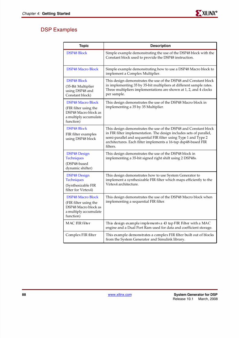
8112019 System Generator for DSP Getting Started
httpslidepdfcomreaderfullsystem-generator-for-dsp-getting-started 9393
AAsynchronous Software Drivers
for FSLs 25
CCompatibility
MATLAB 24 29 34 36
ModelSim 24 29 34 36
Synplify Pro 24 29 34 36
Compiling
Xilinx HDL Libraries 21
Configuring
the Sysgen cache 21
Custom Bus Interfacesfor exported pcore 26
DDownloading
System Generator 19
EExport pcore
enable Custom Bus Interfaces 26
FFast Simplex Link
asynchronous software drivers for 25
H
MMATLAB 24 29 34 36
Memory Stitching 31ModelSim 24 29 34 36
PPcore
export as under development 26
SShared Memory Stitching 31
Software Drivers
asynchronous for FSLs 25System Generator
Cache 21
changing versions 21
displaying versions 21
downloading the software 19
ISE Design Suite Installer 20
System Generator Utilities
xlUpdateModel 37
U
Underdevelopmentexport pcore as 26
XXilinx HDL Libraries
compiling 21
xlUpdateModel 37
Index


