190-00355-00 June 2015 Revision F System Maintenance Manual GDL 69/69A Part 23 AML STC Contains Instructions for Continued Airworthiness for STC SA01487SE Aircraft Make, Model, Registration Number, and Serial Number along with the applicable STC configuration information must be completed in appendix A and saved with aircraft permanent records.
Transcript
190-00355-00 June 2015 Revision F
System Maintenance ManualGDL 69/69A Part 23 AML STC
Contains Instructions for Continued Airworthinessfor STC SA01487SE
Aircraft Make, Model, Registration Number, and Serial Number along with the applicable STC configuration
information must be completed in appendix A and saved with aircraft permanent records.
190-00355-00 System Maintenance Manual GDL 69/69A Part 23 AML STCRev. F Page A
Except as expressly provided herein, no part of this manual may be reproduced, copied, transmitted, disseminated, downloaded or stored in any storage medium, for any purpose without the express prior written consent of Garmin. Garmin hereby grants permission to download a single copy of this manual and of any revision to this manual onto a hard drive or other electronic storage medium to be viewed and to print one copy of this manual or of any revision hereto, provided that such electronic or printed copy of this manual or revision must contain the complete text of this copyright notice and provided further that any unauthorized commercial distribution of this manual or any revision hereto is strictly prohibited.
Garmin® and GDL®, are registered trademarks of Garmin International or its subsidiaries. Garmin Pilot™ is a trademark of Garmin International or its subsidiaries. These trademarks may not be used without the express permission of Garmin.
iOS® is a registered trademark of Cisco in the U.S. and other countries.
SiriusXM®, Sirius®, XM® and all related marks and logos are trademarks of Sirius XM Radio Inc.
All other product or company names that may be mentioned in this publication are trade names, trademarks, or registered trademarks of their respective owners. All rights reserved.
At Garmin, we value your opinion. For comments about this guide, please e-mail: [email protected].
Garmin International Inc.1200 E. 151st StreetOlathe, Kansas 66062 USATelephone: (913) 397-8200www.garmin.com
D 07/20/09Update referenced documents revision in Section 2.1, added STC number in Section 1.1.
E 05/09/11Update referenced documents (2.1). Add periodic bonding test (2.5.2, 2.12). Add GRC 10 battery service (2.4). Clarify ODA role (2.15).
F 06/11/15 Combined maintenance manual and ICA. Added Flight Stream 110 to manual.
Revision Section(s) Description
F AllRewritten to include maintenance manual data and GDL 69/69A SXM data.
190-00355-00 System Maintenance Manual GDL 69/69A Part 23 AML STCRev. F Page i
INFORMATION SUBJECT TO EXPORT CONTROL LAWS
This document may contain information which is subject to the Export Administration Regulations (EAR) issued by the United States Department of Commerce (15 Code of Federal Regulations (CFR), Chapter VII, Subchapter C) and which may not be exported, released, or disclosed to foreign nationals inside or outside of the United States without first obtaining an export license. A violation of the EAR may be subject to a penalty of up to 10 years imprisonment and a fine of up to $1,000,000 under Section 2410 of the Export Administration Act of 1979. Include this notice with any reproduced portion of this document.
This information in this document is subject to change without notice. Visit the Garmin website at www.garmin.com for current updates and supplemental information concerning the operation of Garmin products.
DEFINITIONS OF WARNINGS, CAUTIONS, AND NOTES
WARNINGWarnings indicate that immediate attention must be given to avoid potential equipment damage and personal injury should the instructions be disregarded.
CAUTIONCautions indicate an alert to potential damage to the equipment if the procedural step is not directly followed.
NOTENotes indicate additional information is needed.
190-00355-00 System Maintenance Manual GDL 69/69A Part 23 AML STCRev. F Page ii
1.1 Content, Scope and Purpose ......................................................................................................1-11.2 Organization ..............................................................................................................................1-11.3 Definitions and Abbreviations ..................................................................................................1-21.4 Publications ...............................................................................................................................1-31.5 ICA Revision and Distribution ..................................................................................................1-3
2 SYSTEM OVERVIEW .....................................................................................................................2-1
2.1 System Interfaces ......................................................................................................................2-22.2 Ground Plane .............................................................................................................................2-3
3 GDL 69/69A CONTROL AND OPERATION ...............................................................................3-1
5.1 GDL 69/69A General Troubleshooting .....................................................................................5-15.2 GRT 10/GRC 10 General Troubleshooting ..............................................................................5-35.3 Flight Stream 110 General Troubleshooting .............................................................................5-4
6 REMOVAL AND REPLACEMENT INFORMATION ...............................................................6-1
6.1 Unit Return ................................................................................................................................6-16.2 GDL 69/69A Removal and Reinstallation ................................................................................6-26.3 GRT 10 Removal and Reinstallation ........................................................................................6-46.4 GRC 10 Remote Control Battery Replacement ........................................................................6-56.5 Flight Stream 110 ......................................................................................................................6-66.6 Configuration Module ...............................................................................................................6-76.7 Flight Stream 110 Bonding Strap ..............................................................................................6-9
7 RETURN TO SERVICE ..................................................................................................................7-1
7.1 Return-to-Service Procedures ...................................................................................................7-17.2 Test Procedures .........................................................................................................................7-4
APPENDIX A AIRCRAFT SPECIFIC INFORMATION ..........................................................A-1A.1 GDL 69/69A Configuration Log ..............................................................................................A-2A.2 GRT 10/GRC 10 Configuration Log ........................................................................................A-3A.3 Flight Stream 110 Configuration Log ......................................................................................A-4A.4 Wire Routing ............................................................................................................................A-5A.5 Aircraft Wiring Diagrams ........................................................................................................A-7
APPENDIX B SPECIAL BONDING PROCEDURES ................................................................ B-1B.1 Considerations for Untreated or Bare Dissimilar Metals ......................................................... B-1B.2 Preparation of Aluminum Surfaces .......................................................................................... B-2B.3 Composite Aircraft ................................................................................................................... B-2B.4 Tube and Fabric Aircraft .......................................................................................................... B-7
190-00355-00Rev. F
System Maintenance Manual GDL 69/69A Part 23 AML STC Page iii
190-00355-00 System Maintenance Manual GDL 69/69A Part 23 AML STCRev. F Page 1-1
1 INTRODUCTION
1.1 Content, Scope and Purpose
This document provides Instructions for Continued Airworthiness (ICA) of the GDL 69/69A SiriusXM® satellite receiver, optional GRT 10/GRC 10 wireless remote, and optional Flight Stream 110 Bluetooth® transceiver as installed under STC SA01487SE-D.
1.2 OrganizationThe following outline briefly describes the organization of this manual:
Section 2: System Description
Section 2 provides a description of the equipment installed by STC SA01487SE-D. An overview of the GDL 69/69A, GRT 10/GRC 10, and Flight Stream 110 system interface is also provided.
Section 3: GDL 69/69A Control and Operation
Section 3 provides information on basic control, operation, configuration, and software loading specifically tailored to maintenance practices. Basic GDL 69/69A and GRT 10/GRC 10 configuration mode operation and software loading is also described.
Section 4: Instructions for Continued Airworthiness
Section 4 provides instructions for continued airworthiness of the GDL 69/69A, GRT 10/GRC 10, and Flight Stream 110 systems.
Section 5: Troubleshooting
Section 5 provides troubleshooting information to aid in diagnosing and resolving potential problems with the GDL 69/69A, GRT 10/GRC 10, and Flight Stream 110 equipment.
Section 6: Equipment Removal and Reinstallation
Section 6 provides instructions for the removal and reinstallation of the GDL 69/69A, GRT 10/GRC 10, and Flight Stream 110 equipment.
Section 7: Return to Service
Section 7 provides instructions for testing the GDL 69/69A, GRT 10/GRC 10, and Flight Stream 110 equipment along with return to service procedures to be performed upon completion of maintenance of the GDL 69/69A, GRT 10/GRC 10, and Flight Stream 110 equipment.
Appendix A: Installation Specific Information
Appendix A provides a template to record general installation information and the system configuration log for a specific installation of the GDL 69/69A, GRT 10/GRC 10, and Flight Stream 110 equipment.
190-00355-00 System Maintenance Manual GDL 69/69A Part 23 AML STCRev. F Page 1-2
1.3 Definitions and Abbreviations
Definitions
Except where specifically noted, references made to the GDL 69/69A will be synonymous with all GDL 69 Series unit part numbers.
First generation models are GDL 69 (P/N 011-00986-00) and GDL 69A (P/N 011-00987-00).
Second generation models are GDL 69 SXM (P/N 011-03177-00) and GDL 69A SXM (P/N 011-03177-10).
Throughout this document, references will be made to metallic and nonmetallic aircraft. For the purpose of this manual, metallic aircraft will be those with an aluminum skin. Nonmetallic aircraft will refer to all other aircraft (e.g., wooden aircraft, aircraft with composite skin, or aircraft with tube and fabric construction).
Abbreviations
The following abbreviations/acronyms are used within this document:
AML: Approved Model ListCFR: Code of Federal RegulationsEAR: Export Administration RegulationsFAA: Federal Aviation AdministrationHSDB: High Speed Data BusIAW: In Accordance WithICA: Instructions for Continued AirworthinessLRU: Line Replaceable UnitODA: Organization Designation AuthorizationPED: Portable Electronic DeviceRMA: Return Merchandise AuthorizationSTC: Supplemental Type Certificate
190-00355-00 System Maintenance Manual GDL 69/69A Part 23 AML STCRev. F Page 1-3
1.4 Publications
Table 1-1 lists publications related to the operation and maintenance of the GDL 69/69A, optional GRT 10/GRC 10, and optional Flight Stream 110 devices.
Table 1-1 Garmin Publications
1.5 ICA Revision and Distribution
This manual is a requirement for maintaining the continued airworthiness of the aircraft. Garmin dealers may obtain the latest revision of this document at the Garmin Dealer Resource Center website.
Dealers are notified of manual revision changes via a Garmin Service Bulletin.
Owners and operators may obtain the latest revision of this manual at www.flyGarmin.com or by contacting a Garmin dealer. Garmin contact information is available at www.flyGarmin.com.
Part Number Garmin Document
190-01532-00 Garmin Pilot User’s Guide for Android™
190-01501-00 Garmin Pilot User’s Guide for iOS®
005-C0217-00 GDL 69/69A Part 23 AML STC Master Data List
190-00355-04 GDL 69 Series SiriusXM Satellite Radio Activation Instructions
190-00355-02 GDL 69/69A Part 23 AML STC Installation Manual
190-00355-00 System Maintenance Manual GDL 69/69A Part 23 AML STCRev. F Page 2-1
2 SYSTEM OVERVIEW
The GDL 69/69A is a SiriusXM satellite radio data link receiver (see figure 2-1) performing the following system functions:
Reception of graphical and textual weather data
Reception of audio entertainment data (GDL 69A only)
Output of weather data to interfaced control display device or Portable Electronic Device (PED) via Flight Stream.
Output of audio entertainment data (GDL 69A only)
The optional GRT 10/GRC 10 is a wireless remote system for passengers to control the audio functions of the Garmin GDL 69A data link receiver. The system consists of two components: (1) the GRT 10 wireless transceiver installed in the aircraft and connected to the GDL 69A serial port, and (2) the GRC 10 wireless remote with an LCD display.
The optional Flight Stream 110 Bluetooth transceiver is used to interface the GDL 69/69A to a compatible PED. SiriusXM weather data can be displayed and audio functions (GDL 69A only) can be controlled on the PED.
Figure 2-1 GDL 69/69A
190-00355-00 System Maintenance Manual GDL 69/69A Part 23 AML STCRev. F Page 2-2
2.1 System Interfaces2.1.1 GDL 69/69A Data Link
The GDL 69/69A utilizes High Speed Data Bus (HSDB), RS-232, discrete inputs/outputs, and analog audio inputs/outputs to communicate with other Line Replaceable Units (LRU) and systems on the aircraft. See figure 2-2 for a summary of the GDL 69/69A interfaces.
Figure 2-2 GDL 69 System Interface Diagram
2.1.2 GRT 10
The GRT 10 utilizes RS-232 and discrete inputs to communicate with the GDL 69A.
2.1.3 Flight Stream 110
The Flight Stream 110 communicates with PEDs using Bluetooth technology. RS-232 is used to communicate with the GDL 69/69A and RS-422 is used to communicate with other LRUs.
GarminGDL 69/69A
Flight Stream(Optional)
PED
Audio Panel(GDL 69A Only)
Garmin Display(GDU, GTN, GNS, GMX, etc.)
SiriusXM Antenna
GRT 10 Transceiver(Optional, GDL 69A Only)
GRC 10 RemoteRemote Audio
Switches(Optional, GDL 69A Only)
190-00355-00 System Maintenance Manual GDL 69/69A Part 23 AML STCRev. F Page 2-3
2.2 Ground Plane
For the purpose of this STC, aircraft ground plane definitions vary according to airframe type and aircraft model as defined in table 2-1. Refer to the periodic test and reconditioned resistance values corresponding to these ground plane definitions when performing the equipment bonding test in section 4.3. Ensure that all GDL 69 Series antenna coaxial cables are disconnected during resistance checks.
Table 2-1 Ground Plane Definitions and Ground Path Resistance Requirements
Aircraft Type/ModelGround
Reference
Maximum Resistance Between GDL 69 Series Unit Chassis and
Ground Reference (mΩ) Notes
Periodic Test Reconditioned
Metal airframeNearby Metal Structure
10.0 2.5
Tube and fabric airframeNearby Metal Structure
10.0 2.5
Composite VFR-only Models
Aermacchi S.211A Instrument Panel 50.0 25.0
Diamond
DA20-A1,DA20-C1
Instrument Panel 50.0 25.0
DA 40 Instrument Panel 50.0 25.0
Grob
G115,G115A,G115B
Instrument Panel 50.0 25.0
G115C,G115C2,G115D,G115D2,G115EG
Instrument Panel 50.0 25.0 [2]
G120A Instrument Panel 50.0 25.0 [2]
G520 Egrett,G520T
Instrument Panel 50.0 25.0 [2]
SlingsbyT67M260,T67M260-T3A
Instrument Panel 50.0 25.0
Composite IFR Models
Beech 390Nearby structure lightning ground foil
10.0 5.0
CessnaLC40-550FG,LC41-550FG,LC42-550FG
Nearby aluminum lightning ground bar/strip
10.0 5.0
CirrusSR20,SR22
Local grounded structure (such as seat support structure, entry step)
10.0 5.0
190-00355-00 System Maintenance Manual GDL 69/69A Part 23 AML STCRev. F Page 2-4
[1] Diamond DA 40 and DA 40F with Diamond OSB 40-004/3 incorporated, or aircraft with similar factory-installed lightning protection supporting IFR operation.
[2] Some S/N are IFR from the factory. IFR models must use values of 10.0 and 5.0 for bonding tests, and LRU must be grounded to available lightning ground per manufacturer SRM or other approved data.
Diamond DA 40Nearby structure lightning ground tube
10.0 5.0 [1]
Aircraft Type/ModelGround
Reference
Maximum Resistance Between GDL 69 Series Unit Chassis and
Ground Reference (mΩ) Notes
Periodic Test Reconditioned
190-00355-00 System Maintenance Manual GDL 69/69A Part 23 AML STCRev. F Page 3-1
3 GDL 69/69A CONTROL AND OPERATION
3.1 GDL 69/69A Controls
The GDL 69/69A does not have a direct pilot interface. The GDL 69/69A is controlled via a separately installed control display device, or through a PED, if the Flight Stream 110 is installed. The GDL 69A audio features can be controlled by optional mounted switches (located in the cabin), the optional GRC 10 wireless remote controller if a GRT 10 wireless transceiver is installed, or a PED if a Flight Stream 110 is installed. Refer to the applicable control display pilot’s guide. For GRT 10/GRC 10 installations, refer to GRC 10 User’s Guide for additional information. For Flight Stream 110 installations, refer to Garmin Pilot User’s Guide for iOS or Garmin Pilot User’s Guide for Android, depending on your PED operating system.
3.2 GDL 69/69A Configuration
Configuration and software loading of the GDL 69/69A is performed through the control display device. Refer to the applicable control display device installation manual for configuration procedures and software loading steps.
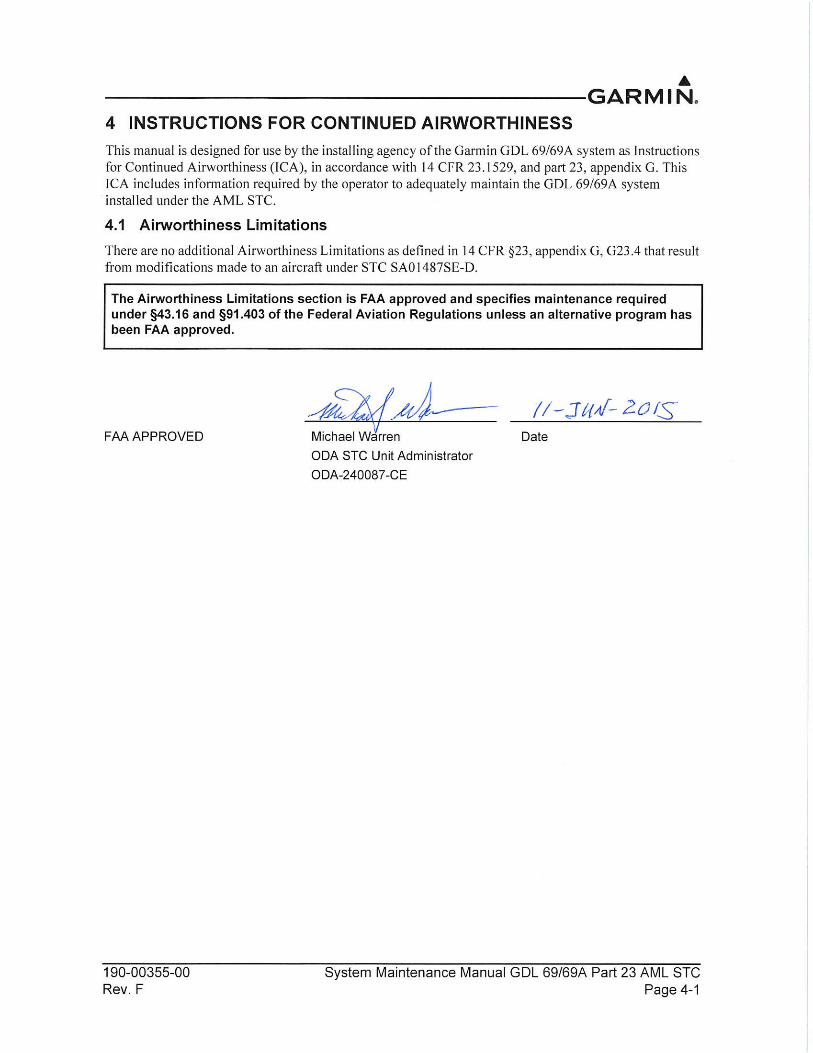
190-00355-00 System Maintenance Manual GDL 69/69A Part 23 AML STCRev. F Page 4-2
4.2 Servicing Information
The GDL 69/69A does not require servicing. In the event of a system failure, troubleshoot the GDL 69/69A in accordance with section 5.
GRC 10 Remote Control Battery Replacement
If the unit does not turn on, or the battery level indicator on the display shows no bars, replace the batteries. See Section 6.4 for details.
NOTEFailure of the GRC 10 (i.e. dead batteries) has no impact on normal aircraft operations and is only used for passengers to control audio entertainment.
4.2.1 Periodic Maintenance
All antennas connected to the GDL 69/69A should be maintained in accordance with appropriate inspection data for the antenna installation.
4.2.2 Special Tools
A milliohm meter with an accuracy of +/- 0.1 mΩ (or better) is required to measure the electrical bonding between the GDL 69/69A system components and aircraft ground.
190-00355-00 System Maintenance Manual GDL 69/69A Part 23 AML STCRev. F Page 4-3
4.3 Maintenance Intervals
Table 4-1 Periodic Maintenance
Item Description/Procedure Interval
Equipment Removal and Replacement
Removal and replacement of the following items. See section 6 for instructions.
• GDL 69/69A unit• GRT 10 unit• Flight Stream 110
On Condition
Battery Replacement
Removal and replacement of GRC 10 batteries. See section 6.4 for instructions.
On Condition
Visual Inspection
The GDL 69/69A, GRT 10 (if installed), Flight Stream 110 (if installed), switches, and wiring harnesses should be inspected to ensure continued integrity of the installation.
Visual inspection of the GDL 69/69A.
1. Inspect the GDL 69/69A for security of attachment, includingvisual inspection of mounting rack and other supporting structure attaching the rack to aircraft.
2. Verify the countersunk fastener heads are in full contact withunit mounting rack holes. If fasteners are loose, re-torque to 12 to 15 in-lbs and complete the electrical bonding test.
3. Inspect for signs of corrosion. If corrosion is found, treat inaccordance with aircraft maintenance manual.
4. Inspect condition of wiring, switches, shield terminations,routing, and attachment/clamping. Correct any issues identified by replacing damaged wiring/shield terminations and re-attaching as necessary. Replace any damaged switches.
Visual inspection of the GRT 10 (if installed).
1. Inspect the GRT 10 for security of attachment.
2. Verify fastener heads are secure. Tighten to snug plusone-quarter turn if necessary.
3. Inspect condition of wiring, shield terminations, routing, andattachment/clamping. Correct any issues identified byreplacing damaged wiring/shield terminations andre-attaching as necessary.
Visual inspection of the Flight Stream 110 (if installed).
1. Inspect the Flight Stream 110 for security of attachment.
2. Verify fastener heads are secure. Tighten to snug plusone-quarter turn if necessary.
3. Inspect condition of wiring, shield terminations, routing, andattachment/clamping. Correct any issues identified byreplacing damaged wiring/shield terminations andre-attaching as necessary.
12 Calendar Months
190-00355-00 System Maintenance Manual GDL 69/69A Part 23 AML STCRev. F Page 4-4
Audio Suppression Verification
Verify each audio suppression input for proper operation.
Verify the GDL 69A audio to the crew headphones is muted when each connected warning alarm system is activated. When possible, activate all warning alarms at the system source. For example, the stall warning may be activated by raising the stall vane on the leading edge of the wing. The gear warning horn may be simulated by providing power or ground, as appropriate, directly to the horn; provided the horn has been tested for proper operation when a gear retraction test was performed.
12 Calendar Months
Electrical Bonding Check
Electrical bonding check of GDL 69/69A
1. Remove the GDL 69/69A from the mounting rack.
2. Remove the backplate assembly from the rack to disconnectthe cable harnesses.
3. Measure the resistance between the mounting rack andground location as defined by table 2-1, verifying that theresistance is less than or equal to the periodic test valuedefined by table 2-1. If the bonding check fails, perform thefollowing procedures:
a) Remove the rack and verify that the countersunk areasaround the holes are free of corrosion or any otherdebris.
b) Clean all metal contact points with a bonding brush.
c) Reattach the rack and verify the resistance between themounting rack and nearby exposed aircraft metallicstructure, ensuring that the resistance is less than orequal to the reconditioned test value defined bytable 2-1.
4. Reinstall the backplate assembly then reinstall theGDL 69/69A in the mounting rack.
Every 10 years or 2000 flight hours, whichever comes first.
Item Description/Procedure Interval
190-00355-00 System Maintenance Manual GDL 69/69A Part 23 AML STCRev. F Page 4-5
Electrical Bonding Continued
Electrical bonding check of Flight Stream 110 (metallic or tube/fabric aircraft).
1. Disconnect the shield terminations from the Flight Stream110 connector backshell.
2. Measure the resistance between the connector and groundlocation defined by table 2-1, and check that it is less than orequal to 20 milliohms. If the bonding check fails, perform thefollowing procedures:
a) Remove the Flight Stream 110 connector bonding strapfrom the aircraft ground plane and clean the attachmentpoint with a bonding brush.
b) Re-attach the bonding strap to the aircraft ground plane,torque to 12 to 15 in-lbs. Verify the resistance betweenthe Flight Stream 110 connector and aircraft structure,ensuring that the resistance is less than or equal to 10milliohms.
c) If cleaning the aircraft ground plane side of the strap isnot enough, remove, clean, and re-attach on theFlight Stream 110 side. Verify the resistance between theFlight Stream 110 connector and aircraft structure,ensuring that the resistance is less than or equal to 10milliohms.
3. Reattach the shield terminations to the Flight Stream 110connector backshell.
Electrical bonding check of Flight Stream 110 (composite aircraft).
1. Disconnect the shield terminations from the Flight Stream110 connector backshell.
2. Measure the resistance between the connector and groundlocation defined by table 2-1, and check that it is less than orequal to 20 milliohms. If the bonding check fails, perform thefollowing procedures:
a) Remove the Flight Stream 110 connector bonding strapfrom the aircraft ground plane and clean the attachmentpoint with a bonding brush.
b) Re-attach the bonding strap to the aircraft ground plane,torque to 12 to 15 in-lbs. Verify the resistance betweenthe Flight Stream 110 connector and aircraft structure,ensuring that the resistance is less than or equal to 10milliohms.
c) If cleaning the aircraft ground plane side of the strap isnot enough, remove, clean, and re-attach on the FlightStream 110 side. Verify the resistance between the FlightStream 110 connector and aircraft structure, ensuringthat the resistance is less than or equal to 10 milliohms.
3. Reattach the shield terminations to the Flight Stream 110connector backshell.
Item Description/Procedure Interval
190-00355-00 System Maintenance Manual GDL 69/69A Part 23 AML STCRev. F Page 5-1
5 TROUBLESHOOTING
5.1 GDL 69/69A General Troubleshooting
Information is provided in this section to assist with troubleshooting if problems occur after maintenance. Refer to the GDL 69/69A configuration log retained in the aircraft permanent records for a list of the interfaced equipment and system configuration data. When troubleshooting the GDL 69/9A, GRT 10/GRC 10, or Flight Stream 110, refer to the wire routing drawings and interconnect wiring diagrams that are retained in the aircraft permanent records.
After completing each corrective action, perform the appropriate return to service procedure in accordance with section 7. If any system fault persists after performing the associated troubleshooting actions, return the GDL 69/69A to Garmin for Service. See section 6 for details.
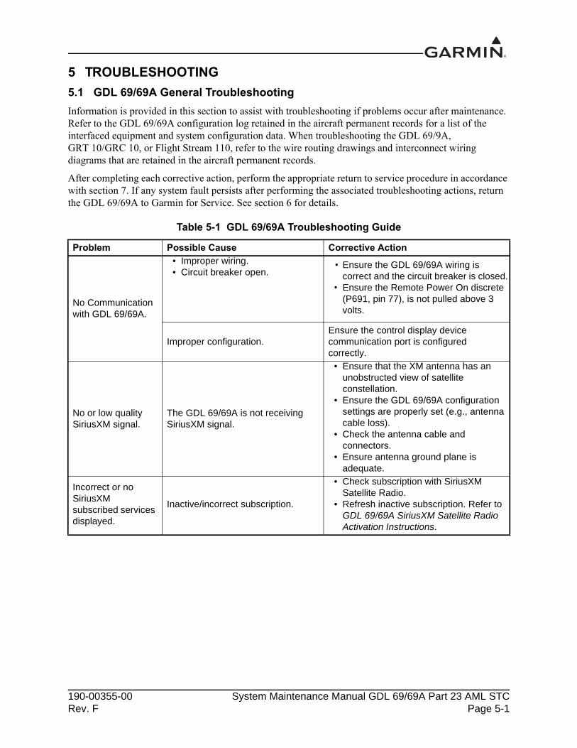
Table 5-1 GDL 69/69A Troubleshooting Guide
Problem Possible Cause Corrective Action
No Communication with GDL 69/69A.
• Improper wiring.• Circuit breaker open.
• Ensure the GDL 69/69A wiring iscorrect and the circuit breaker is closed.
• Ensure the Remote Power On discrete(P691, pin 77), is not pulled above 3volts.
Improper configuration.Ensure the control display device communication port is configured correctly.
No or low quality SiriusXM signal.
The GDL 69/69A is not receiving SiriusXM signal.
• Ensure that the XM antenna has anunobstructed view of satelliteconstellation.
• Ensure the GDL 69/69A configurationsettings are properly set (e.g., antennacable loss).
• Check the antenna cable andconnectors.
• Ensure antenna ground plane isadequate.
Incorrect or no SiriusXM subscribed services displayed.
Inactive/incorrect subscription.
• Check subscription with SiriusXMSatellite Radio.
190-00355-00 System Maintenance Manual GDL 69/69A Part 23 AML STCRev. F Page 5-2
No audio output (GDL 69A only)
• Installed unit is GDL 69.• No audio output from GDL 69A.• Improper wiring.
• Verify installed unit is GDL 69A, not GDL 69 (with no audio feature).
• Check wiring of audio suppression input. Check that wiring is going to correct active high or active low input sense.
• Check the wiring from GDL 69A to audio panel.
• Verify that mute is not on.• Increase volume by pressing Volume
Up.• If there is audio output only on channel
1, verify that audio SiriusXM service has been activated. Refer to GDL 69 Series SiriusXM Satellite Radio Activation Instructions, for more details.
SiriusXM audio entertainment does not mute when audio suppression interfaced inputs (stall, gear) are activated (GDL 69A only).
Improper wiring.
• Check wiring of audio suppression inputs.
• Check alarm activation state of warning.
• Verify that audio is not connected to Line Output.
No response to control commands on GRC 10 Remote Control (GDL 69A only).
GRC 10 is not communicating with GRT 10.
• Check the batteries in GRC 10 Remote Control.
• Check wiring between GDL 69A and GRT 10.
• Verify GRT 10 is not mounted behind RF blocking material (i.e., bulkhead).
Problem Possible Cause Corrective Action
190-00355-00 System Maintenance Manual GDL 69/69A Part 23 AML STCRev. F Page 5-3
5.2 GRT 10/GRC 10 General Troubleshooting
Table 5-2 GRT 10/GRC 10 Troubleshooting
Problem Possible Cause Corrective Action
GRC 10 will not power on.
GRC 10 needs fresh batteries.• Check that batteries are installed.• Install fresh batteries. See section 6.4
for details.
GRT 10 not found.
• GRT 10 has lost power.• GRT 10 is mounted incorrectly.• GRC 10/GRT 10 are not paired.
• Check GRT 10 is receiving power.• Verify GRT 10 is not mounted behind
RF blocking material (i.e. bulkhead).• Verify that the RF pairing ID entered
into GRC 10 is correct.• Change mounting orientation of
GRT 10. For optimal performance, the end of the GRT 10 opposite the 9-pin D-sub should face the cabin.
GRT 10 connection lost.
• GRT 10 has lost power.• GRT 10 is mounted incorrectly.
• Check that GRC 10 is in RF range of the GRT 10.
• Check GRT 10 power and wiring.• Verify GRT 10 is not mounted behind
RF blocking material (i.e. bulkhead).• Change mounting orientation of
GRT 10. For optimal performance, the end of the GRT 10 opposite the 9-pin D-sub should face the cabin.
GDL 69A not found.
• GDL 69A has lost power.• Improper Wiring.• Improper configuration.
• Check that GDL 69A is powered on.• Check wiring between GDL 69A and
GRT 10.• If GDL 69A is using a software version
older than 3.10, verify that GRT 10 is not connected to RS-232 port 1.
GDL 69A connection is lost.
• GDL 69A has lost power.• Damaged wiring.
• Check that GDL 69A is powered on.• Check wiring between GDL 69A and
GRT 10.
190-00355-00 System Maintenance Manual GDL 69/69A Part 23 AML STCRev. F Page 5-4
5.3 Flight Stream 110 General Troubleshooting
Table 5-3 Flight Stream 110 Troubleshooting
Problem Possible Cause Corrective Action
Unable to pair PED to Flight Stream
Flight Stream paired device storage is full.
Refer to the list of paired devices and verify that the queue is not full. If thirteen devices have been previously paired with the Flight Stream, remove one device from the list to pair the new device with the Flight Stream.
Ensure that the Flight Stream has the latest certified software version.
Check software version and update if there is a newer approved version.
PED is not receiving any data from Flight Stream
Devices need to be re-synced with each other.
1. Remove the list of Bluetooth devices on the PED.
2. Re-pair the devices.
PED is not receiving data from the GDL 69 (e.g., datalink weather) Flight Stream has lost
communication with the GDL 69.
1. Check that PED is paired to Flight Stream. See steps above for details.
2. Check that the Flight Stream 110 connector is fully seated.
3. Check RS-232 wires and connections between the GDL 69 and Flight Stream 110.
4. Check power and ground wires and connections to the Flight Stream 110.
PED will not control GDL 69 SiriusXM audio
190-00355-00 System Maintenance Manual GDL 69/69A Part 23 AML STCRev. F Page 6-1
6 REMOVAL AND REPLACEMENT INFORMATION
This section describes how to remove and replace equipment associated with this STC. The mounting location of the GDL 69/69A, GRT 10, and Flight Stream 110 may vary between aircraft listed on the STC Approved Model List.
CAUTIONWhen removing and/or replacing a GDL 69/69A, GRT 10, Flight Stream 110, or any other item under the scope of the STC installation, always ensure that the aircraft power is off. Unplug any auxiliary power supply.
6.1 Unit Return
A Return Merchandise Authorization (RMA) number must be obtained from Garmin before a Garmin unit is returned. Units returned without an RMA will be refused and returned at the sender’s expense. See page A for contact information to request an RMA. Send units with assigned RMA numbers to the following address:
Garmin International, Inc.Factory Repair1200 E. 151st St.RMA Number:__________Dock Door #20Olathe, KS 66062
190-00355-00 System Maintenance Manual GDL 69/69A Part 23 AML STCRev. F Page 6-2
6.2 GDL 69/69A Removal and Reinstallation
Removal
1. Remove power from the GDL 69/69A.
2. Locate the locking lever handle securing screw (4) at the bottom of the unit face.
3. Using a Phillips screwdriver, turn the fastener counterclockwise until the handle is loose and can be freely lifted.
4. Lift the locking lever handle (1) and slide the GDL 69/69A unit out of the rack.
Reinstallation
1. Verify power has not been applied.
2. With the locking lever handle raised, slide the GDL 69/69A straight into the rack until it stops about 1" short of the fully seated position.
3. After fully inserting the unit into the mount rack, visually note that the cam head (2) remains seated in the slot of the locking plate (3).
4. With the unit firmly engaged with the mount rack, lower the locking lever handle (1). Then insert and tighten the locking lever handle securing screw (4) to mechanically secure the unit to the remote mount rack.
NOTEWhen inserting the GDL 69/69A into the remote mount rack, it may be possible for the pivot pin to fit between the unit and the mount rack without going into the slot of the locking plate (3). If the cam head (2) does not seat in the slot of the locking plate (3), the unit will not firmly engage with the mount rack and the unit could come loose from the rack.
CAUTIONStart the handle screw in the hole carefully to avoid cross-threading. The application of torque exceeding 14 in-lbs to this screw will damage the LRU case and/or retaining hardware.
CAUTIONDo not use excessive force when inserting the GDL 69/69A into the rack. This may cause damage to occur to the connectors, unit, and/or unit rack. If heavy resistance is felt during installation, STOP! Remove the GDL 69/69A and identify the source of resistance. The unit is designed with a key and the back plate is designed to float in the unit rack. Check to ensure the rear plate is not bound by the connector harness.
5. Once the GDL 69/69A is reinstalled, verify the GDL 69/69A unit operation by viewing SiriusXM Satellite information, checking the SiriusXM Information page, or checking the SiriusXM Status page on the control display device. If the GDL 69/69A unit is removed for repair and reinstalled, or if the GDL 69/69A unit is removed and replaced with a different GDL 69/69A unit, the GDL 69/69A XM radio service may require re-activation. Refer to GDL 69 Series SiriusXM™ Satellite Radio Activation Instructions for additional information.
190-00355-00 System Maintenance Manual GDL 69/69A Part 23 AML STCRev. F Page 6-3
Figure 6-1 GDL 69/69A Mounting Rack Assembly
190-00355-00 System Maintenance Manual GDL 69/69A Part 23 AML STCRev. F Page 6-4
6.3 GRT 10 Removal and Reinstallation
Removal
1. Remove power from the GRT 10.
2. Push the slide lock lever and remove the connector from the GRT 10 unit.
3. Locate the four #6 mounting screws for the unit and unscrew them, removing the GRT 10 unit.
Reinstallation
1. Ensure that the GRT 10 unit is not receiving power.
2. Reinstall the GRT 10 unit using the four previously removed #6 mounting screws. Tighten fasteners until snug and turn an additional one-quarter turn.
3. Attach the connector, pushing until the slidelock clicks into place. Check that slidelock is fully engaged.
4. Apply power to the GRT 10.
5. If the GRT 10 or GRC 10 is replaced, the GRC 10 remote controller must be configured to recognize the GRT 10 transceiver. See section 7.1.3 for instructions.
CAUTIONCare should be taken when applying torque to the mounting screws of the GRT 10. Excessive torque may damage the mounting flange.
Figure 6-2 GRT 10
190-00355-00 System Maintenance Manual GDL 69/69A Part 23 AML STCRev. F Page 6-5
6.4 GRC 10 Remote Control Battery Replacement
To replace the batteries in the GRC 10 Remote Control, remove the back cover of the remote. Insert fresh batteries with the orientation as shown in the diagram in the battery compartment. Both batteries should be replaced with fresh batteries at the same time.
Figure 6-3 GRC 10 Remote Control Battery Department
WARNINGDo not use lithium batteries in the GRC 10.
CAUTIONWhen replacing batteries, use only new or fully charged batteries. Do not mix new and old batteries as this can cause battery leakage and damage to the unit. Do not mix battery types (i.e. rechargeable with non-rechargeable).
CAUTIONRemove batteries if the GRC 10 will not be in use for extended periods. Storing batteries in the unit for prolonged periods may result in leakage and damage to the battery compartment.
NOTEThe GRC 10 remote control contains two AA batteries. If the battery is not replaced and becomes totally discharged, the GDL 69/69A system will remain fully operational. There is no impact on normal aircraft operations from a fully discharged battery.
190-00355-00 System Maintenance Manual GDL 69/69A Part 23 AML STCRev. F Page 6-6
6.5 Flight Stream 110
See figure 6-4 when performing the following steps:
Removal
1. Remove power from the Flight Stream 110.
2. Unscrew the two jackscrews on the Flight Stream connector. Remove connector.
3. Locate the four #6 mounting screws for the unit and unscrew them, removing the Flight Stream device.
Reinstallation
1. Ensure that power is removed from the Flight Stream 110.
2. Reinstall the Flight Stream 110 using the four previously removed #6 mounting screws. Tighten fasteners until snug and turn an additional one-quarter turn.
CAUTIONCare should be taken when applying torque to the mounting screws of the Flight Stream 110. Excessive torque may damage the mounting flange.
3. Attach the connector, tightening the two jackscrews.
4. Apply power to the Flight Stream 110.
Figure 6-4 Flight Stream Assembly Overview
190-00355-00 System Maintenance Manual GDL 69/69A Part 23 AML STCRev. F Page 6-7
6.6 Configuration Module
The P691 connector assembly serves as the housing for the configuration module.
Removal
1. Disconnect the configuration module wiring harness pins (4) from the P691 connector.
2. Remove two screws (8) from cover (7) and remove cover. See figure 6-5.
3. Unplug the configuration module wiring harness connector (2) from the configuration module (1).
4. Remove the configuration module from the backshell (6).
5. If necessary, remove the wiring harness pins (4) from the P691 connector.
Reinstallation (Original Unit)
1. Ensure there are no damaged wires (4) or pins (3) on the configuration module wiring harness.
2. Place the configuration module (1) in position.
3. Insert the configuration module wiring harness connector (2) into the configuration module (1).
4. Insert the wiring harness pins (4) into the P691 connector.
5. Place the cover (7) back on the connector and reinstall screws (8). See figure 6-5.
6. Perform the return to service procedures in accordance with section 7.
Installation (New Configuration Module)
1. Ensure there are no damaged wires (4) or pins (3) on the configuration module wiring harness.
2. Place the configuration module (1) in position.
3. Insert the configuration module wiring harness connector (2) into the configuration module (1).
4. Insert the wiring harness pins (4) into the P691 connector.
5. Place the cover (7) back on the connector and reinstall screws (8). See figure 6-5.
6. Perform the configuration and return to service procedures in accordance with section 7.
190-00355-00 System Maintenance Manual GDL 69/69A Part 23 AML STCRev. F Page 6-8
NOTEEnsure that the repaired or replaced unit is configured per the original configuration log that is maintained with the aircraft records.
Figure 6-5 Backshell Assembly
1
4
7
8
6
5
2x
3
190-00355-00 System Maintenance Manual GDL 69/69A Part 23 AML STCRev. F Page 6-9
6.7 Flight Stream 110 Bonding Strap
The following removal and replacement steps are provided as guidance for replacing the Flight Stream bonding strap. The bonding strap assembly drawing is shown in figure 6-6.
NOTEAircraft structure side of bonding strap may be mounted using a nut in lieu of a nut plate. If a nut was used in lieu of a nut plate, further disassembly of the aircraft may be required to gain access to the nut.
Removal
1. Disconnect one end of the bonding strap from the aircraft ground location.
2. Disconnect the other end of the bonding strap from the shield block on the Flight Stream connector backshell.
3. Remove the bonding strap.
Replacement
NOTEThe Flight Stream bonding strap should be as short as practical and must not exceed 20". When installed, the bonding strap must not loop back on itself.
1. Construct a bonding strap no longer than 20" by attaching 10 AWG terminal lugs to both ends of 1/4" braid (QQB575R36T0250) or wider.
2. If needed, clean the attachment locations with a bonding brush.
3. Secure each end of the bonding strap to the previously installed locations. Ensure that the strap does not loop back on itself and that the hardware is as shown in figure 6-6. The washers must seat fully against the aircraft metallic structure, without overhang or interference from other hardware.
Using a milliohm meter, verify that the resistance between the connected structure is less than 10 mΩ.
190-00355-00 System Maintenance Manual GDL 69/69A Part 23 AML STCRev. F Page 6-10
In the event of a bonding test failure, remove the bonding strap from the aircraft ground point and clean the attachment point with a bonding brush. Re-install the bonding strap and perform the electrical bonding test in accordance with section 4.3 again.
Figure 6-6 Flight Stream Bonding
Table 6-1 Flight Stream Bonding Hardware
See figure 6-6 Hardware P/N
1 Screw AN515, AN515B, or AN515C
2 Lock washer MS35338-137
3 Flat washer NAS1149CN832R or AN960C-8
4Terminal Lugs (7 AWG or 10 AWG depending on size of braid)
MS25036
5 Screw MS51957-42
6 BraidQQB575R36T0250 (or wider braid)
3
31
2
4
5
2
46
3
190-00355-00 System Maintenance Manual GDL 69/69A Part 23 AML STCRev. F Page 7-1
7 RETURN TO SERVICE
This section provides return-to-service procedures to be followed after removal and reinstallation or replacement of equipment covered by this STC. After conducting all of the procedures in this section, the aircraft may be returned to service.
7.1 Return-to-Service Procedures
7.1.1 GDL 69/69A
Original GDL 69/69A Reinstalled
If the removed GDL 69/69A is installed in its original position, no software loading or configuration setting changes are required. This does not include units that were returned for repair as their software and configuration files are deleted during the repair testing progress.
New, Repaired, or Exchanged GDL 69/69A Installed
If a new, repaired, or exchanged GDL 69/69A is installed, the correct software must be loaded to the unit. Some configuration files must be set. See the summary in Table 7-1. The GDL 69/69A SiriusXM radio service must be activated. Refer to GDL 69 Series SiriusXM Satellite Radio Activation Instructions for details.
7.1.2 Configuration Module
Original Configuration Module Reinstalled
No return-to-service procedures are required.
New Configuration Module Installed
Reconfigure the system using the configuration settings in the configuration log kept with the aircraft permanent records. Configuration is done through the interfaced control display device. Refer to the appropriate display installation manual.
190-00355-00 System Maintenance Manual GDL 69/69A Part 23 AML STCRev. F Page 7-2
7.1.3 GRT 10/GRC 10
Original GRT 10/GRC 10 Reinstalled
No return-to-service procedures are required.
New, Repaired, or Exchanged GRT 10/GRC 10 Installed
Configure RF Pairing ID of the GRC 10:
NOTEGRT 10 serial number is required for installation. Serial number is located on the bottom of the unit.
1. Insert two AA batteries in GRC 10.
2. On the GRC 10 press any key to power the remote.
3. When the “GRT 10 not found” message is displayed on the GRC 10, press the following buttons in order:
UP, DOWN, LEFT, RIGHT, MINUS (-), PLUS (+), PSET
4. Use the arrow buttons on the GRC 10 to enter the serial number of the GRT 10 transceiver, which is installed in the aircraft. Verify the correct GRT 10 transceiver serial number has been entered.
5. Press the XM button to store the GRT 10 serial number.
Verify volume and channel control through GRC 10.
190-00355-00 System Maintenance Manual GDL 69/69A Part 23 AML STCRev. F Page 7-3
7.1.4 Flight Stream 110
Original Flight Stream 110 Reinstalled
No return-to-service procedures are required.
New, Repaired, or Exchanged Flight Stream 110 Installed
Configure Bluetooth pairing of the Flight Stream 110 device:
When the Flight Stream device is powered on, the Flight Stream 110 will immediately go into pairing mode.
1. Enable Bluetooth on the PED to be connected to the Flight Stream.
2. Select the Flight Stream 110 from the list of available Bluetooth devices on the PED. The default Flight Stream Bluetooth name is “Flight Stream” followed by the three-digit model number (110) and then the last four digits of the MAC address (e.g., Flight Stream 110 4000).
NOTEIf having issues making a Bluetooth connection, cycle power on the Flight Stream device. Retry making a Bluetooth connection.
NOTEA compatible PED with the Garmin Pilot application is required to perform the following checks.
3. Verify Flight Stream is paired with Bluetooth device. Verify volume and channel control.
4. Verify the XM WX data is being received and displayed on the PED (aircraft must have a clear view of the sky).
5. If the Volume Lock Discrete input is grounded, ensure the SiriusXM satellite radio volume controls on the PED are not available or do not work.
7.1.5 System Wiring
If any work has been done on the aircraft that could affect the system wiring, antenna cable, or any interconnected equipment, verify the GDL 69/69A unit operation by viewing SiriusXM satellite information on the control display device, or by checking the SiriusXM information or SiriusXM status page on the control display device. Verify the GRT 10 and GRC 10 unit operation by viewing SiriusXM radio channel information on the GRC 10 display or by viewing the SiriusXM radio channel information by using the Flight Stream 110 and a PED.
If any new aircraft navigation or communication system is installed or a change is made to the existing configuration in the aircraft after the GRC 10/GRT 10 or Flight Stream 110 has been installed, conduct the GRC 10/GRT 10 or Flight Stream 110 configuration and checkout procedure as described in Table 7-1.
190-00355-00 System Maintenance Manual GDL 69/69A Part 23 AML STCRev. F Page 7-4
7.2 Test Procedures
To validate the operation of the GDL 69/69A, monitor the control display device weather depiction page and look for display of weather data. Depiction of weather data should begin within 10 minutes. Refer to the applicable display device pilot’s guide.
To validate the operation of the optional GRT 10/GRC 10 remote system, use the GRC 10 to change SiriusXM radio channel or volume and monitor the GRC 10 display or audio from the audio panel. Refer to GRC 10 User’s Guide for additional information.
To validate the operation of the optional Flight Stream 110, monitor the PED display weather depiction page and look for display of weather data. Depiction of weather data should begin within 10 minutes. Use the PED to change SiriusXM channel or volume and monitor the PED display or audio from the audio panel. Refer to Garmin Pilot User’s Guide for additional information.
Table 7-1 Configuration and Checkout Procedures
Modification Required Action
Replacing GDL 69/69A with equivalent unitComplete GDL 69/69A Configuration Log. See Appendix A.1 for details.
Replacing Configuration module with new module
1. Complete System Configuration. Refer to GDL 69/69A Installation Manual for details.
2. Complete GDL 69/69A Configuration Log. See Appendix A.1 for details.
Replace GRC 10
1. Complete GRC 10 configuration. Refer to GDL 69/69A Installation Manual for details.
2. Complete GRT 10/GRC 10 Configuration Log. See Appendix A.2 for details.
3. Complete GRT 10/GRC 10 Function Check. Refer to GDL 69/69A Installation Manual for details.
Replace GRT 10
1. Complete GRC 10 configuration. Refer to GDL 69/69A Installation Manual for details.
2. Complete GRT 10/GRC 10 Configuration Log. See Appendix A.2 for details.
3. Complete GRT 10/GRC 10 Function Check. Refer to GDL 69/69A Installation Manual for details.
Replace a Flight Stream 110
1. Complete Flight Stream 110 Configuration Log. See Appendix A.3 for details.
2. Complete Flight Stream 110 Function Check. Refer to GDL 69/69A Installation Manual for details.
190-00355-00 System Maintenance Manual GDL 69/69A Part 23 AML STCRev. F Page A-1
APPENDIX A AIRCRAFT SPECIFIC INFORMATION
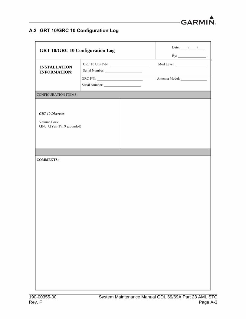
A copy of this appendix must be used to record information for a specific installation of the GDL 69/69A, GRT 10/GRC 10, and Flight Stream 110. A copy of this information must be maintained with the aircraft permanent records. This appendix includes the following information:
GDL 69/69A system configuration log
GRT 10/GRC 10 configuration log
Flight Stream 110 configuration log
An electronic fillable form is available here. Refer to the attachments panel of this manual. This form may also be downloaded from the Garmin Dealer Resource Center website. Acrobat Reader 8.0 or later is necessary to view and fill out the form. You can download Acrobat Reader by visiting www.adobe.com.
GDL 69/69A InstallationsRemote Power Discrete Enabled N/A
RS-232 Serial Interface Ethernet PortsPort 1 Device __________ Port 1 Device __________Port 2 Device __________ Port 2 Device __________Port 3 Device __________ Port 3 Device __________ Port 4 Device __________Gain/Loss (GLcomp) ValueCalculated Value ________
GDL 69A Installations Only Audio Output Line OutputDevice ____________Device ____________
Audio Suppression Input Audio/Channel Control#1 N/A Active ______ Volume Control N/A #2 N/A Active ______ Volume Mute N/A#3 N/A Active ______ Channel Control N/A#4 N/A Active ______ Preset Option N/A#5 N/A Active ______#6 N/A Active ______
Flight Stream 110 Unit P/N: ______________________ Mod Level:_______________
Serial Number: _____________________
CONFIGURATION ITEMS:
Flight Stream Discretes
Volume Lock:No Yes (Pin 1 grounded)
COMMENTS:
190-00355-00 System Maintenance Manual GDL 69/69A Part 23 AML STCRev. F Page A-5
A.4 Wire Routing
Single Engine
The following diagram depicts approximate location of all LRUs and antenna(s) along with the wire routing for the GDL 69/69A, optional GRT 10, and optional Flight Stream 110 throughout the aircraft structure for a single-engine aircraft.
Figure A-1. Wire Routing - Single Engine
190-00355-00 System Maintenance Manual GDL 69/69A Part 23 AML STCRev. F Page A-6
Twin Engine
The following diagram depicts approximate location of all LRUs and antenna(s) along with the wire routing for the GDL 69/69A, optional GRT 10, and optional Flight Stream 110 throughout the aircraft structure for a twin-engine aircraft.
Figure A-2. Wire Routing - Twin Engine
190-00355-00 System Maintenance Manual GDL 69/69A Part 23 AML STCRev. F Page A-7
A.5 Aircraft Wiring Diagrams
Attach the aircraft wiring diagrams showing the equipment installed by this STC or a markup of the interconnect diagrams from the STC installation manual detailing which equipment was installed and how it was installed.
NOTEElectrical loads for equipment installed by this STC are listed in the GDL 69/69A STC Installation Manual.
190-00355-00 System Maintenance Manual GDL 69/69A Part 23 AML STCRev. F Page B-1
APPENDIX B SPECIAL BONDING PROCEDURES
Refer to SAE ARP1870 section 5 when surface preparation is required to achieve electrical bond.
B.1 Considerations for Untreated or Bare Dissimilar Metals
The correct material finish is important when mating untreated or bare dissimilar metals. Materials should be galvanically-compatible. When corrosion protection is removed to make an electrical bond, any exposed area after the bond is complete should be protected again. Additional guidance can be found in AC 43.13-1B and SAE ARP1870. Typical electrical bonding preparation examples are shown in figure B-1, figure B-2, and figure B-3.
190-00355-00 System Maintenance Manual GDL 69/69A Part 23 AML STCRev. F Page B-2
B.2 Preparation of Aluminum Surfaces
The following general procedure is recommended to prepare an aluminum surface for proper electrical bonding.
1. Clean grounding location with solvent.
2. Remove non-conductive films or coatings from the grounding location.
3. Apply a chemical conversion coat such as Alodine 1200 to the bare metal.
4. Once the chemical conversion coat is dry, clean the area.
5. Install bonding equipment at grounding location.
6. After the bond is complete, if any films or coatings were removed from the surface, reapply a suitable film or coating to the surrounding area.
For a more detailed procedure, refer to SAE ARP1870 sections 5.1 and 5.5.
B.3 Composite Aircraft
Use the following guidance when repairing or replacing special bonding components. Use aluminum tape (3M P/N 438 or other adhesive-backed dead soft aluminum foil with minimum metal thickness of 7.2 mils) when replacing existing aluminum foil that has been damaged. A tape maximum length-to-width ratio of 7:1 must be maintained (i.e., up to seven inches in length for every one inch in width.) A minimum tape width of 6 inches is required for bonding strips under this STC. Maintain the existing aluminum tape routing, while maintaining the same width as the tape being replaced. Additional guidance can be found in AC 43.13-1B and SAE ARP1870, sections 5.1 and 5.5.
Additional considerations:
Ensure isolation from the carbon composite material is maintained to prevent corrosion due to dissimilar materials.
The GDL 69/69A ground must be routed to the aircraft ground reference specified in table 2-1.
The aluminum tape must not have any tears in the joint or along the length of the tape, as tears will degrade the bonding performance.
The tape must be folded over twice to itself. The folded area is covered with a thin aluminum plate to avoid damage from fasteners and to
provide good contact with all tape strips. Mating metal-to-metal contact surfaces must be carefully cleaned to ensure good contact. The plate and tape are secured to the mating metal part with multiple fasteners.
190-00355-00 System Maintenance Manual GDL 69/69A Part 23 AML STCRev. F Page B-3
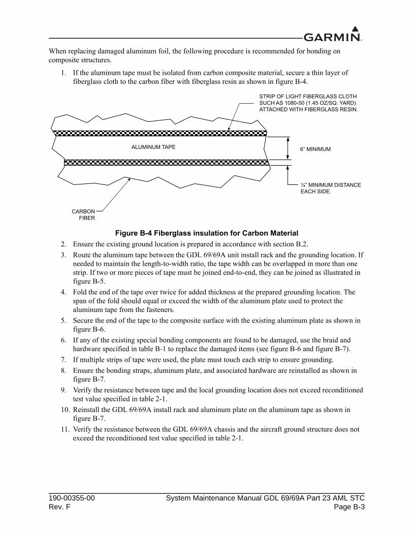
When replacing damaged aluminum foil, the following procedure is recommended for bonding on composite structures.
1. If the aluminum tape must be isolated from carbon composite material, secure a thin layer of fiberglass cloth to the carbon fiber with fiberglass resin as shown in figure B-4.
Figure B-4 Fiberglass insulation for Carbon Material
2. Ensure the existing ground location is prepared in accordance with section B.2.
3. Route the aluminum tape between the GDL 69/69A unit install rack and the grounding location. If needed to maintain the length-to-width ratio, the tape width can be overlapped in more than one strip. If two or more pieces of tape must be joined end-to-end, they can be joined as illustrated in figure B-5.
4. Fold the end of the tape over twice for added thickness at the prepared grounding location. The span of the fold should equal or exceed the width of the aluminum plate used to protect the aluminum tape from the fasteners.
5. Secure the end of the tape to the composite surface with the existing aluminum plate as shown in figure B-6.
6. If any of the existing special bonding components are found to be damaged, use the braid and hardware specified in table B-1 to replace the damaged items (see figure B-6 and figure B-7).
7. If multiple strips of tape were used, the plate must touch each strip to ensure grounding.
8. Ensure the bonding straps, aluminum plate, and associated hardware are reinstalled as shown in figure B-7.
9. Verify the resistance between tape and the local grounding location does not exceed reconditioned test value specified in table 2-1.
10. Reinstall the GDL 69/69A install rack and aluminum plate on the aluminum tape as shown in figure B-7.
11. Verify the resistance between the GDL 69/69A chassis and the aircraft ground structure does not exceed the reconditioned test value specified in table 2-1.
ALUMINUM TAPE
CARBONFIBER
STRIP OF LIGHT FIBERGLASS CLOTHSUCH AS 1080-50 (1.45 OZ/SQ. YARD)ATTACHED WITH FIBERGLASS RESIN.
¼” MINIMUM DISTANCEEACH SIDE.
6” MINIMUM
190-00355-00 System Maintenance Manual GDL 69/69A Part 23 AML STCRev. F Page B-4
Table B-1 Composite Airframe Bonding Hardware
Figure B-5 Aluminum Tape Joint
Item Number Description
1
Tinned copper flat braid, 3/4", QQB575F36T781
OR
Tinned copper tubular braid, 7/16", QQB575R30T437
2 Terminal lug, 5-16", uninsulated, MS20659-131
3 BOlt, 5/16", AN5-XA
4 Lock washer, 5/16", NASM35338-45
5 Flat washer, 5/16", NAS1149F0563P
6 Flat washer, 0.063" thick, NASM970-5 (AN970-5)
7 Locknut, 5/16", AN363-535
190-00355-00 System Maintenance Manual GDL 69/69A Part 23 AML STCRev. F Page B-5
Figure B-6 Aluminum Tape Ground Termination
ALUMINUMTAPE
0.063" ALUMINUM PLATE
3 BOLTS WITH LOCKNUTS AND WASHERS
GROUND STUD-COMMON TO
BONDING STRAPREQUIRED IF SECONDARY STRUCTURE IS NOT BONDED TO THE
SECONDARY STRUCTURE
A A
VIEW A-A(NOT TO SCALE)
0.063" ALUMINUM PLATE
SECONDARY STRUCTURE
ALUMINUM TAPE
21
3
456
67
190-00355-00 System Maintenance Manual GDL 69/69A Part 23 AML STCRev. F Page B-6
Figure B-7 GDL 69/69A Aluminum Tape Installation
190-00355-00 System Maintenance Manual GDL 69/69A Part 23 AML STCRev. F Page B-7
B.4 Tube and Fabric Aircraft
Installation in tube and fabric aircraft commonly involves the GDL 69/69A install rack being mounted to a plate or shelf which is mounted to the tube structure. If it is necessary to replace the existing bonding clamp(s) used to bond the mounting surface to the tube structure, install new conductive clamp(s) for bonding in accordance with AC 43.13-1B chapter 11 and the following criteria.
Table B-2 Materials Required but Not Supplied
1. Ensure all surface preparation material (e.g., primer, paint, etc.) is removed between the clamp and the metallic tube over an area which is equal to the width of the clamp and 1" minimum length (circumference) for steel tubes; 2" minimum length (circumference) for attachment to aluminum tubes.
2. Reinstall bonding clamp(s) using hardware from table B-2. See figure B-8 for additional detail regarding use of AN742 clamps.
3. Once installed, verify the resistance between the GDL 69/69A chassis and the aircraft ground structure does not exceed the reconditioned test value specified in table 2-1.
4. After assembly and bonding check, prime the airframe tube and clamp in accordance with one of the following:
• The approved aircraft maintenance manual• MIL-PRF-85285 Type I, color to suit (36081 Flat Gray preferable) coating: polyurethane,
aircraft and support equipment• MIL-PRF-23377 Type I, class N, primer coatings: epoxy, high-solids
RS-232 Serial Interface Ethernet PortsPort 1 Device __________ Port 1 Device __________Port 2 Device __________ Port 2 Device __________Port 3 Device __________ Port 3 Device __________
Port 4 Device __________Gain/Loss (GLcomp) ValueCalculated Value ________
GDL 69A Installations Only Audio Output Line Output
Device ____________Device ____________
Audio Suppression Input Audio/Channel Control#1 N/A Active ______ Volume Control N/A #2 N/A Active ______ Volume Mute N/A#3 N/A Active ______ Channel Control N/A#4 N/A Active ______ Preset Option N/A#5 N/A Active ______#6 N/A Active ______