http://www.iaeme.com/IJMET/index.asp 378 [email protected]
International Journal of Mechanical Engineering and Technology (IJMET) Volume 8, Issue 9, September 2017, pp. 378–390, Article ID: IJMET_08_09_041
Available online at http://www.iaeme.com/IJMET/issues.asp?JType=IJMET&VType=8&IType=9
ISSN Print: 0976-6340 and ISSN Online: 0976-6359
© IAEME Publication Scopus Indexed
SYSTEM MODEL TOOLING FOR INJECTION
MOLDING
Svitlana Sotnik
Department of Computer-Integrated Technologies, Automation and Mechatronics,
Kharkiv National University of RadioElectronics, Kharkiv, Ukraine
Rami Matarneh
Department of Computer Science,
Prince Sattam Bin Abdulaziz University, Al-Kharj, Saudi Arabia
Vyacheslav Lyashenko
Department of Informatics,
Kharkiv National University of RadioElectronics, Kharkiv, Ukraine
ABSTRACT
Optimization of scientific research and the introduction of their results into the real
process is the basis for the development of modern production. The solution of such a
problem can be achieved by modeling the objects and processes under study. To do
this, we consider the process of molding plastic parts under pressure. We formalized
the model of technological equipment for injection molding. This allows us to perform
static and dynamic modeling of the creation and management of complex structures.
Key words: System Model, Tooling, Injection Molding, Plastic Parts.
Cite this Article: Svitlana Sotnik, Rami Matarneh and Vyacheslav Lyashenko,
System Model Tooling For Injection Molding, International Journal of Mechanical
Engineering and Technology 8(9), 2017, pp. 378–390.
http://www.iaeme.com/IJMET/issues.asp?JType=IJMET&VType=8&IType=9
1. INTRODUCTION
Nowadays, one of the essential tasks of modern technological progress is the optimization of
ongoing researches and make use of their results in the real world problems, this can be
achieved by modeling the studied objects and processes. However, the design of the tooling
(TO) and analysis of the stages of its development, as well as other equally important tasks
better solved by modeling with the aim of considering the impact of the design features,
parameters or stages of the process on the quality of the products. System simulation is a
versatile method that can be applied to any systems and tasks [1-3].
The practical significance of this method explores a "not shown" and can be not only a
tool of analysis and explanation of the properties of system objects, but also to predict new
System Model Tooling For Injection Molding
http://www.iaeme.com/IJMET/index.asp 379 [email protected]
properties, to be a "prediction tool" behavior and synthesis of systems with predetermined
properties.
Plastics are indispensable in many fields of engineering and the modeling tooling for
manufacture of plastic components are specific [4-6].
A great variety of geometric forms and dimensions, requirements for dimensional
accuracy and accuracy of the mutual arrangement of surfaces, a wide range of polymer
materials and the related differences in their technological properties require an individual
approach to the design of the equipment, compromise and often unconventional solutions.
The rational system model, and subsequently quality production equipment allows to
ensure the required accuracy of dimensions of parts, to the surface without any traces of
sprues and ejectors, etc.
In this research, TO implies molding form (MF) for molding plastic parts. Modeling
objects, namely, TO describes the position of system approach. The definition of a set of
elements, relations between elements, the possible states of each element, essential
characteristics of states and the relations between them.
2. MATERIALS AND METHODS
2.1 Literature review on the research topic
The basic principles of the design of tooling for injection molding and its constructive
features inherent in the work [7], where there is a full review of all aspects of the process of
molding that goes from practical to theoretical, and from elementary to advanced. Describe
the key features of computer for the design of plastic parts and most tooling.
The work [8] devoted to new methods and tools to support the design process to get more
effective solution when designing tooling (molds). The proposed multidisciplinary structure
based on the methodology "Design for six Sigma". Focuses on the platform to support the
design of any instrument for the mold without undercuts, which optimizes the design of the
equipment.
In [9] analyzed a recent study in the field of mathematical modeling and optimization of
the casting process under pressure, the considered optimization methods, which include
design of experiments, artificial neural networks and evolutionary algorithms. The article also
discusses the optimization study conducted in occurred injecting Molding (IM) process, in
respect of certain characteristics associated with this element, as a system of ejection and the
configuration of the cooling channel, process conditions, location of intake and balancing the
pressure in the forming cavity. Presents current research on the mathematical modeling of the
IM process, with an explanation of the process simulations and the benefits of each particular
model. Learn how DOE, ANN and EA.
The method of experiments planning (Design of Experiment (DOE)) – a systematic
approach to the study of the system or process. DOE includes: analysis of change process; the
determination of optimal process parameters; determination of the optimal design process [9-
11].
The method of "Artificial Neural Networks" (ANN) is a combination of nonlinear
transformations of the input data with the ability to recover the complex non-linear
dependencies. Prediction based on the inverse of the error distribution [9, 11, 12].
Svitlana Sotnik, Rami Matarneh and Vyacheslav Lyashenko
http://www.iaeme.com/IJMET/index.asp 380 [email protected]
The method of "Evolutionary algorithms" (EA) is used when finding the optimal solution
takes a long time and is quite complex. The efficiency of the evolutionary algorithm depends
on the choice of the values of its parameters. Selection of parameters can be carried out before
starting the evolutionary algorithm. However, the optimal parameter values may change
during the course of the algorithm. Therefore, the required method of adaptive adjustment
parameters in the optimization process. The values parameters of the evolutionary algorithm
lie in a given interval of values. The task of choosing parameter values discretizing, dividing
the range values of the parameter into intervals. Partitioning into intervals may be performed
before running the algorithm and does not vary in the course of his work. However, the
change in partitioning during the work contributes to the improvement of the algorithm [10,
13].
We can also use image analysis techniques and voice control to robotize the casting
process [14-16].
2.2 Modeling tooling
The ultimate goal of design is obtaining the best technical solution among possible
alternatives. This is achieved in the process of solving the synthesis problem, which aims at
determining the optimal structure and parameters of the object.
In the process of the automated designing and creation of computer aided design the
ability of structural-parametric description of the snap-in is essential, as it shows from what
units, parts, nodes and how these components interact, what are their weight, dimensional
characteristics, which will allow us to generate many alternatives to MF.
Considering parametric modeling to build tooling (shape) by solving the equations that
express the geometric relationships with equations that describe the specified dimensions and
the relationships between them.
In parametric modeling the build tooling is usually carried out in the following sequence:
1. Construction drawing.
2. Enter interactive mode, geometric relationships, and data on the size of snap.
3. Construction drawing that meets the restrictions and requirements sizes.
4. Steps 2 and 3 are repeated with a change in limits or dimensions until getting the right model.
5. Create a three-dimensional model of a plane figure. The thickness and the angle of rotation
can also be dimensional parameters which makes it possible to easily change the created three-
dimensional shape if necessary. Form in parametric modeling is changed not directly, but
through using geometric relations and dimensions, therefore the designer can develop many
alternative projects, not caring about the details, but focusing on functional aspects.
Considering the structural modeling TО is assumed to be the correct organization
structure of all the subsystems, which determines the optimal functioning of the entire snap, in
general.
The structure of each subsystem may vary depending on internal and external factors of
the casting process.
The essence of the relationship well-built the structure of the system with the results of its
work.
Let the System Ω – is a finite set of elements (E) and a regulating device (R), which
establishes relationships between items ( ie ) and transformation management, managing
System Model Tooling For Injection Molding
http://www.iaeme.com/IJMET/index.asp 381 [email protected]
relationships, creating an indivisible unit of function. Topologically, the system shown in Fig.
1 [17].
Figure 1 Topological diagram of the system
where ie – the elements of the system, Eei ∈ ,
R – control (regulate) device,
iK – link to transform the inputs to outputs, Kk i ∈ ,
X – input (a lot of impact ( Xx i ∈ )),
Y – output (multiple outputs ( Yyi ∈ )),
– a transducer (resolver) that distinguishes input and output from the effects of
management (regulation),
if – regard for the impact on the system in terms of regulation, ffi ∈ ,
iF – feedback, transferring the impact on regulation F,
EN – the external environment,
Z – internal resources (internal state) system.
The structure of a simple system can be represented in the form of a vector:
∑=
⇒→1J
Фk21 ,...)S,...,S,S(F , (1)
where k21 S,...,S,S – the element of jth
subsystem, which can also be system,
J – the hierarchy degree of the system,
Ф – the purpose of the jth
subsystem,
F – management subsystems.
A complex system is a system that has a large number of elements ( max→Ω , that is
power element set E tends to a maximum), which has a complex goal structure of internal
states ( max→Ω ), that is a set of resources Z has a maximum power), complex conversion
function and the structural system is specified as a multilevel hierarchical system.
Formalization of the calculation of structural parameters of the system Ω can be
presented taking into consideration a number of key structural indicators [17, 18] as follows:
Svitlana Sotnik, Rami Matarneh and Vyacheslav Lyashenko
http://www.iaeme.com/IJMET/index.asp 382 [email protected]
1) Complexity – is a metric value, which corresponds to: the number of elements and relations
between them Ω
С (structural complexity) and complexity in system functions F
С (the
functional complexity), F
ССс +Ω
= where
−⋅⋅−−=
∑=
+
=Ω
)1()1()1(
1)1(
lrlrkkNN
M
m
ii
ki
c
С
µ
ξµ
, (2)
where N – the number of levels in the system Ω ,
k – the number of elements in the system level Ω ,
r – the number of inputs of the system (average expression),
l – the number of outputs of the system (average expression),
M – the amount of actually implemented in the system Ω ,
ξ – the relative coefficient for a functioning system in a real environment,
ic – the manufacturing element complexity of the i
th type,
ik – the number of elements of the i
th type in the system,
m – the number of all elements in the system.
entsation_elem_implementcomplexity
sation_link_implementcomplexity=ξ . (3)
If the system is defined as a project, that is, in statics,
µ=c . (4)
Functional complexity F
С can be defined as
оk)LM(С
F×= , (5)
where M – is the number of parallel jobs;
L – the most difficult job (the length of the longest chain of the process),
оk – the relative ratio associated with the implementation of the system in the
implementation environment.
2) The reliability W – is a metric value that is associated with the ability of the system to
maintain the desired properties of the behavior under internal and external influences on the
system, that is:
)),1i
t,i
t(,H
T),1i
t,i
t(P,T(D
W+
∆+
φ= (6)
where T – the average time an infallible (error free, trouble free) operation of the system,
P – the probability of the number of failures in the time interval (1i
t,i
t+
),
System Model Tooling For Injection Molding
http://www.iaeme.com/IJMET/index.asp 383 [email protected]
HT – during normal operation of the system, that is the time from the beginning of system
operation until the result of the accumulation of errors and failures, the system starts to work
poorly,
)1i
t,i
t(+
∆ – the number of failures (errors) in this time interval (1i
t,i
t+
).
The formula applies to the already existing system. If the system is designed, the
reliability is computed by the formula:
))#S#,N,k(~~C(~см
Wν
ϕ=ϕ= , (7)
where #S# – the number of subsystems in the system.
The equations (4), (5), (6) and (7) are applicable if the system is given as a scheme (draft).
3) The bandwidth of П determines the max/min system operation time 21
ППП += .
#S#
#I
S#
1П = , (8)
K)LH(
M
2П
×= , (9)
where #I
S# – number of identical subsystems with elements that own the media outlets,
L – the length of the computational chain,
H – the degree of "parallelism" (the number of concurrent jobs),
#S# – the number of subsystems in the system.
4) U – versatility. How many activities can be embodied in the system. The relationship
between inputs and output is called the way of the action item:
N
KU
1
ν= (10)
#S#
#S~
#U
*
2= (11)
where ν
K – the number of elements with the maximum number of different types of
inputs,
N – the number of all elements in the system,
#S~
#* – the number of subsystems of different functions,
#S# – the number of subsystems in the system.
5) The information content of the system εI .
N
KI I
=ε
, (12)
Svitlana Sotnik, Rami Matarneh and Vyacheslav Lyashenko
http://www.iaeme.com/IJMET/index.asp 384 [email protected]
where I
K – the number of elements with the maximum number of same type of outputs;
– the total number of elements.
6) Hierarchy εY
#Y#
#Y#Y
f
=ε
, (13)
where #Y#f – the number of equations (paths) according to the types of hierarchies:
management, information, functions, activities and time;
#Y# – the total number of equations (paths) in the system.
The smallest hierarchy fY must be managed and the most function.
Thus, before building the system we need to determine the main indicators (1–13).
3. RESULTS
On the basis of the decomposition of elements [19] forms according to their structural
characteristics, it is possible to develop a system model TO, which will be a formal
presentation that allows us to use methods of computer processing system models in order to
be able to analyze and perform formal operations on them.
The proposed system model presented as a graph as shown in Fig. 2. analyzing such
representation of the structure of technological equipment is difficult, so it is desirable present
system model TO in a form that convenient for computer processing. Therefore, we represent
the MF model in term of the extended regular system models (ERSM):
[ ]n21 MFMFMFMF R...RRR ∧∧∧= , (14)
where [ ]n21n SSSSSSMF R...RRR ∧∧∧= ,
where [ ]n21n ТТТSS R...RRR ∧∧∧= ,
\
where [ ]n21n vVvТ R...RRR ∧∧∧= ,
where [ ]n21 CECECEnV R...RRR ∧∧∧= ,
where nCER – system model of n
th structural element of n-view of n-type of n
th subsystem
of the nth
injection mold.
By substituting the expression nVR to
nТR , and, accordingly, nТR into
nSSR and so on
it is possible to obtain a system model in the basis of parts, kinds, types, subsystems and
alternatives to MF.
System Model Tooling For Injection Molding
http://www.iaeme.com/IJMET/index.asp 385 [email protected]
Figure 2 The structure of tooling
MF1, MF2, MF3, MF4 – alternative to injection molds,
SS 1 – The subsystem formalizing the details,
SS 2 – The subsystem centering,
SS 3 – The subsystem of removal of the casting from the mold,
SS 4 – The subsystem cooling and temperature control,
SS 5 – The subsystem gating and suction channels.
Т 1…N – The type of the of nth
subsystem,
V 1…N – Element view n-type of nth
subsystem,
CE 1…N – The feature of n-form of n-type of nth
subsystem.
Each constructive element (CE) has a lifetime distributed across the phases of the life
cycle (LC): design of CE, production of CE, operation of CE, modernization of CE and CE
disposal.
By considering every constructive element, the model of MF can have presented as shown
in Fig. 3.
Figure 3 Phases of the life cycle of each part included in MF
Svitlana Sotnik, Rami Matarneh and Vyacheslav Lyashenko
http://www.iaeme.com/IJMET/index.asp 386 [email protected]
Presenting phases of the life cycle of CE model in term of ERSM will take the following
form:
DpMzOpPrDsCE RRRRRRn
⋅⋅⋅⋅= , (15)
During the life cycle, at each phase, the CE is a complex hierarchical system whose model
can be displayed in the following form (see Fig. 4).
Figure 4 Morphological cube project activity
In Fig. 4 the following should be noted:
edL – element-level design (base design), gL – group level, ssL – subsystem level, sL –
system level, МL – metasystem level, MSL – level of the nth
metasystem. At each level of the
design of the object there are different aspects of the design: T – target, F – functional, OT –
organizational-technical, I – infological, AF – functioning algorithm. D – decomposition of
the top level design stratified properties of the project operation and performance
characteristics, TTC – development of tactical and technical characteristics decomposition
elements of the strata of the project action, CSM – construction of the system model of strata
design, SM – system modeling for the correspondence of the developed tactical and technical
characteristics of the decomposed stratum elements, tactical and technical requirements of the
general goal for the structural element of the MF.
On the target stratum, the system target model is constructed from MF decomposition. In
general, the target system model has a hierarchical tree structure, which is based on the main
purpose of the system, in this case a complete formal representation of MF.
Functional stratum is the construction of a system functional model of this level that
reflects the structure of functional tasks, their parameters, relationships among themselves. In
addition to the known set of characteristics (performance, accuracy, reliability), there may be
specific ones belonging to this technological equipment.
System Model Tooling For Injection Molding
http://www.iaeme.com/IJMET/index.asp 387 [email protected]
The organizational and technical stratum determines the means by which the solution of
the ith
level tasks is realized. All the means at which the tasks of this level will be solved,
combined by ties, will constitute a model of the organizational and technical structure of the
tooling. It is necessary to determine the attainability of goals and objectives. This requires
TTC estimation of the performance characteristics of the organizational structure and their
functional necessity. The development of tactical and technical characteristics of decomposed
elements implies the basic properties of MF (strength, accuracy, etc.).
At the infological stratum formed a system information model, which determines the
structure and characteristics of information flows. The basis for its construction is the
functional model and organizational structure of this level.
Considering the input and output parameters of the solution of each task on an element of
the organizational structure, the developer examines information flows on the organizational
structure with their volumetric and temporal characteristics, defining the organizational
structure by the system communication channels.
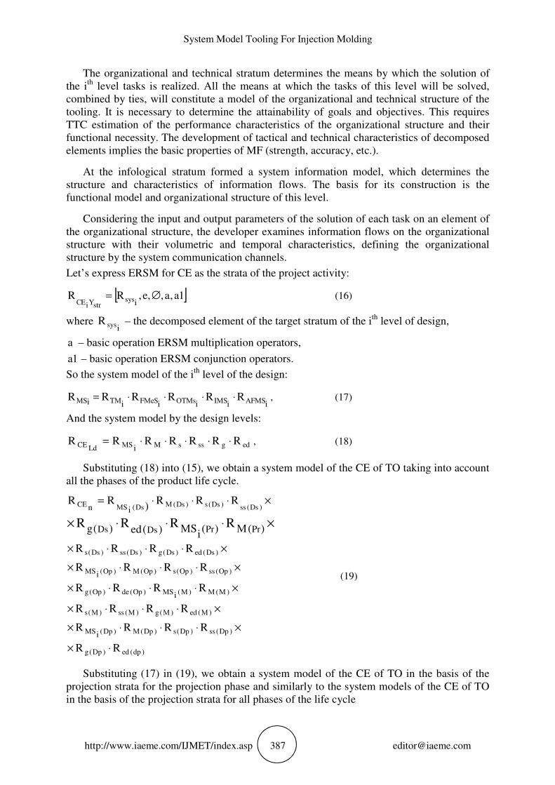
Let’s express ERSM for CE as the strata of the project activity:
[ ]1a,a,,e,RRisys
strYiEС∅= (16)
where isysR – the decomposed element of the target stratum of the i
th level of design,
a – basic operation ERSM multiplication operators,
1a – basic operation ERSM conjunction operators.
So the system model of the ith
level of the design:
iiiiii МSАFМSIМsОTМеSFМTМS RRRRRR ⋅⋅⋅⋅= , (17)
And the system model by the design levels:
edgsssMМSLdCE RRRRRRRi
⋅⋅⋅⋅⋅= , (18)
Substituting (18) into (15), we obtain a system model of the CE of TO taking into account
all the phases of the product life cycle.
)dp(ed)Dp(g
)Dp(ss)Dp(s)Dp(М)Dp(МS
)М(ed)М(g)М(ss)М(s
)М(М)М(МS)Op(de)Op(g
)Op(ss)Op(s)Op(М)Op(МS
)Ds(ed)Ds(g)Ds(ss)Ds(s
)Ds(ss)Ds(s)Ds(МDs(МSCE
RR
RRRR
RRRR
RRRR
RRRR
RRRR
)(М)(i
МS)(ed)(g
RRR)
RR
i
i
i
in
PrPrDsDsRRRR
⋅×
×⋅⋅⋅×
×⋅⋅⋅×
×⋅⋅⋅×
×⋅⋅⋅×
×⋅⋅⋅×
×⋅⋅⋅=
×⋅⋅⋅×
(19)
Substituting (17) in (19), we obtain a system model of the CE of TO in the basis of the
projection strata for the projection phase and similarly to the system models of the CE of TO
in the basis of the projection strata for all phases of the life cycle
Svitlana Sotnik, Rami Matarneh and Vyacheslav Lyashenko
http://www.iaeme.com/IJMET/index.asp 388 [email protected]
Having constructed system models of CE LF for project activities, design strata, design
levels and phases of the life cycle of CE, then expressing them in the form of a program, a
formal representation of the CE in the language of regular schemes of system models is
obtained, which will make it possible to use computer processing methods of system models
in order to they could be analyzed and carried out formal actions on them.
Constructing a systemic model of the CE of TO for project activities, strata design, level
design phases of the CE life cycle and expressing them in the form of a program, a formal
representation in the language of regular schemes of system models is obtained, which will
make it possible to use computer methods for processing system models in order to be able to
analyze them and perform formal actions on them.
4. DISCUSSIONS
With the obtained systemic patterns of the CE of TO, is possible to perform static and
dynamic simulation to create and manage complex structures of TO designs.
Developed a system model TO is a formal representation of a snap-in that allows the use
of methods of computer processing system models in order to be able to analyze and perform
formal operations on them.
The choice of TO design is influenced by factors that must be taken into account when
fulfilling the requirements. The developed model differs from the existing ones in that the
choice of the TO design as a whole consists in determining the necessary equipment, optimal
nesting, structure and arrangement of the most advantageous variants of systems capable of
satisfying the technical and production-economic requirements for this product with
unconditional reliability of the form itself.
The technical requirements consist in providing its geometric shape, surface roughness
and dimensional accuracy by maintaining the properties of the projected raw material in the
finished product with allowable, residual and orientational stresses to achieve the required
stability of these parameters.
The most important performance requirements to the manufacture of the product are: its
low cost, high performance, trouble-free operation of form and minimum employment.
5. CONCLUSION
A further development of the system model TO with the possibility of a new class of objects.
The proposed system model contains a description of constructive elements of the MF in the
form of morphological cube with nodes at each hierarchical level given projection operations,
grouped by project activity and strata design, level design phases of the CE life cycle.
This gave the opportunity to obtain a complete formal representation in term of the
language of regular schemes of system models and to use methods of computer processing of
formal system models.
System Model Tooling For Injection Molding
http://www.iaeme.com/IJMET/index.asp 389 [email protected]
REFERENCES
[1] Marusich, T. D., and Modeling Ortiz. Modelling and simulation of high-speed machining.
International Journal for Numerical Methods in Engineering, 38(21), 1995, pp. 3675–
3694.
[2] Karnopp, Dean C., Donald L. Margolis, and Ronald C. Rosenberg. System dynamics:
modeling, simulation, and control of mechatronic systems, 5th Edition. New York, USA:
John Wiley & Sons, Inc, 2012.
[3] Yu, L., Koh, C. G., Lee, L. J., Koelling, K. W., and Madou, M. J. Experimental
investigation and numerical simulation of injection molding with micro-features. Polymer
Engineering & Science, 42(5), 2002, pp. 871–888.
[4] Chen, C. P., Chuang, M. T., Hsiao, Y. H., Yang, Y. K., and Tsai, C. H. Simulation and
experimental study in determining injection molding process parameters for thin-shell
plastic parts via design of experiments analysis. Expert Systems with Applications, 36(7),
2009, pp. 10752–10759.
[5] Yang, H., Zhan, M., Liu, Y. L., Xian, F. J., Sun, Z. C., Lin, Y., and Zhang, X. G. Some
advanced plastic processing technologies and their numerical simulation. Journal of
Materials Processing Technology, 151(1), 2004, pp. 63–69.
[6] Atzeni, E., Iuliano, L., Minetola, P., and Salmi, A. Redesign and cost estimation of rapid
manufactured plastic parts. Rapid Prototyping Journal, 16(5), 2010, pp. 308–317.
[7] Rosato, D. V., and Rosato, M. G. (2012). Injection molding handbook. New York, USA:
Springer Science & Business Media, 2000.
[8] Ferreira, I., Cabral, J. A., Saraiva, P., and Oliveira, M. C. A multidisciplinary framework
to support the design of injection mold tools. Structural and Multidisciplinary
Optimization, 49(3), 2014, pp. 501–521.
[9] Fernandes, C., Pontes, A. J., Viana, J. C., and Gaspar-Cunha, A. Modeling and
Optimization of the Injection-Molding Process: A Review. Advances in Polymer
Technology. 2016, рp. 21683–21704.
[10] Dobslaw, F. A Parameter Tuning Framework for Metaheuristics Based on Design of
Experiments and Artificial Neural Networks. World Academy of Science, Engineering and
Technology, 64, 2010, pp. 213–216.
[11] Ries, J., Beullens, P., and Salt, D. Instance-specific multi-objective parameter tuning
based on fuzzy logic. European Journal of Operational Research, 218(2), 2012, pp. 305–
315.
[12] Calvet, L., Juan, A. A., Serrat, C., and Ries, J. A statistical learning based approach for
parameter fine-tuning of metaheuristics. SORT-Statistics and Operations Research
Transactions, 1(1), 2016, pp. 201–224.
[13] Ramos, I. C., Goldbarg, M. C., Goldbarg, E. G., and Neto, A. D. D. Logistic regression
for parameter tuning on an evolutionary algorithm. In Evolutionary Computation, 2, 2005,
1061–1068.
[14] Putyatin, Y. P., Lyashenko, V. V., Ahmad, M. A., Lyubchenko, V. A., and Ahmad, N. A.
A Theoretical Interpretation for the Study of Images Processing. International Journal of
Advance Research in Computer Science and Management Studies, 3(9), 2015, pp. 17–31.
[15] Maksymova, S., Matarneh, R., and Lyashenko, V. V. Software for Voice Control Robot:
Example of Implementation. Open Access Library Journal, 4(8), 2017, pp. 1–12.
[16] Maksymova, S., Matarneh, R., Lyashenko, V. V., and Belova, N. V. Voice Control for an
Industrial Robot as a Combination of Various Robotic Assembly Process Models. Journal
of Computer and Communications, 5(11), 2017, pp. 1–15.
[17] Hopkins, T. K., and Wallerstein, I. M. World-systems analysis: theory and methodology.
Beverly Hills; London; New Dehli: Sage, 1982.
Svitlana Sotnik, Rami Matarneh and Vyacheslav Lyashenko
http://www.iaeme.com/IJMET/index.asp 390 [email protected]
[18] Blanchard, B.S., and W.J. Fabrycky. Systems Engineering and Analysis, 5th ed. Prentice
Hall International Series in Industrial and Systems Engineering. Englewood Cliffs, NJ,
USA: Prentice Hall, 2011.
[19] B. Benhadou, A. Haddout, M. Benhadou, H. Bakhtari,Study and optimization of the
injection molding of composites based on short hemp fibers. International Journal of
Mechanical Engineering and Technology, 7(4), 2016, pp. 38–47.
[20] Basma Benhadou, Abdellah Haddout, Mariam Benhadou, Houssam Ourchid, Study of
thermorheological behavior of polypropylene composites reinforced with short hemp
fibers during industrial injection molding process. International Journal of Mechanical
Engineering and Technology, 7(4), 2016, pp. 29–37
[21] Sotnik, S.V. Strukturno-parametrichne modelyuvannya tehnologіchnoї osnastki / S.V.
Sotnik // Radioelektronika i molodej v HHI veke_ 13_i Mejdunarodnii molodejnii forum –
2009 g. – tez. dokl. – H. – 2009. – s. 111.