7
System Sump and Pump VICTRON MULTIPLUS COMPACT 12/800/35 & 12/1200/50 - Advanced Battery Backup System Rev 2.2 - 10 October 2017 © Newton Waterproofing Systems Operational Manual ®

System Sump and Pump
VICTRON MULTIPLUS COMPACT12/800/35 & 12/1200/50 - Advanced Battery Backup System
Rev 2.2 - 10 October 2017© Newton Waterproofing Systems
Operational Manual
®

2 For more information visit us online www.newtonwaterproofing.co.uk Call us for more information on +44 (0)1732 360095 3
The Victron range of Inverter/Chargers provide advanced solutions to ensure that Newton Pumping Systems continue pumping during power interruption by inverting 12V DC power from a battery (or multiple batteries) to clean and efficient 230V power.
The MultiPlus Compact is a powerful pure sine wave inverter, a sophisticated battery charger that features adaptive charge technology and a high-speed AC transfer switch in a single compact enclosure.
WARRANTY STATEMENTThe Victron Inverter/Chargers are covered by a 5-year warranty. Warranty includes next day on-site replacement (delivery and collection, not decommission and installation) of the Inverter/Charger units by a temporary replacement of the same model. If the warranty claim is upheld, this temporary unit will be exchanged with a new unit. If the warranty claim is not upheld, the client must decide the course of action, which will include purchase of a new replacement unit, purchase of the temporary replacement unit, or return of the original unit.
Limited Product Warranties. 5-year limited product warranty from date on delivery note or invoice to the customer.
WHAT IS COVERED BY THIS LIMITED HARDWARE WARRANTY?
This limited warranty covers replacement (Newton Waterproofing Systems) only for defects in materials and workmanship.
WHAT IS NOT COVERED BY THIS LIMITED HARDWARE WARRANTY?
• Products the supplier has not received payment for
• Normal wear and tear
• Failure to follow product installation instructions and user instructions
• Usage that is not in accordance with the product instructions
• Servicing not authorised by the manufacturer
• Problems caused by connecting devices not supplied or authorised by the manufacturer
WARRANTY INFORMATION
This warranty gives you specific legal rights, and you may also have other rights which may vary from area to area (or jurisdiction to jurisdiction). The manufacturer’s responsibility for malfunctions and defects in the product is limited to repair and replacement as set forth in this warranty statement. All expressed and implied warranties for the product (including but not limited to any implied warranties and conditions of merchantability and fitness for a particular purpose), are limited in time to the term of the limited warranty which is the 2-year period reflected on your delivery note or invoice. No warranties, whether expressed or implied, will apply after the limited warranty period has expired.
We do not accept liability beyond the remedies provided for in this limited product warranty or for consequential or incidental damages, including without limitation, any liability for third-party claims against you, for damages for products not being available for use. Our liability will be no more than the amount you paid for the product that is the subject of a claim. This is the maximum amount for which we are responsible. Newton Waterproofing Systems reserve the right to change the product specification at any time.
INTRODUCTION CONTENTS
PAGE
INFORMATION 4
DIMENSIONS 4
SAFETY INSTRUCTIONS 4
INVERTER SIZING 5
TYPICAL DETAILS 5
INSTALLATION 6 - 9
QUICK INSTALL GUIDE 9
OPTIONAL CONNECTIONS 10
CONFIGURATION 10
BATTERY SELECTION 10
OPERATION 11
MAINTENANCE 11
TECHNICAL DATA 11
TROUBLESHOOTING 12

4 For more information visit us online www.newtonwaterproofing.co.uk Call us for more information on +44 (0)1732 360095 5
This Operational Manual is written by Newton Waterproofing Systems specifically for the use of the Victron Inverter Charger units used with Newton Pumping Systems to ensure continued pumping during power outages. The original Victron installation manual may be used for reference but contains no specific information on the use of the unit as a Newton Battery Backup System. It mentions uses that are not applicable to the Newton System, therefore may be confusing when read in isolation.
DIMENSIONS375 mm high x 214 mm wide x 110 mm deep.
Weight - 10 kg.
SAFETY INSTRUCTIONSGENERAL
Please familiarise yourself with the safety features and instructions by first reading this document before using the equipment. This product has been designed and tested in accordance with international standards. The equipment must be used exclusively for the purpose for which it was designed.
WARNING: ELECTRIC SHOCK HAZARD.
The product is used in conjunction with wall mains, a permanent energy source (battery). Input and/or output terminals may still be dangerously energized, even when the equipment is switched off. ALWAYS SWITCH OFF THE AC IN SUPPLY AND DISCONNECT FROM MAINS AND BATTERY WHEN INSTALLING, MAINTAINING OR SERVICING THIS SYSTEM. The product has no internal user-serviceable components. Do not remove the front plate or operate the product if any panels have been removed. All servicing must be undertaken by a qualified professional.
Never use the product where there is a risk of gas or dust explosions. Consult the battery manufacturer’s information to ascertain that the product is intended for use in conjunction with the battery. Always comply with the battery manufacturer’s safety instructions.
WARNING: DO NOT LIFT HEAVY LOADS WITHOUT ASSISTANCE.
INSTALLATION
Read these installation instructions in full before installing the equipment. This is a Safety Class I product (supplied with a protective grounding terminal for safety purposes). Uninterrupted protective grounding must be provided at the AC input and/or output terminals. Alternatively the grounding point located externally on the product may be used. Whenever it is likely that the grounding protection has been damaged, the product must be turned off and secured against unintended operation; please contact qualified service staff.
Ensure that the DC and AC input cables are fused and fitted with circuit breakers. Never replace a safety component with a different type.
Before applying power, ensure that the available power source matches the configuration settings of the product. This manual is to be used with the Victron MultiPlus 12/800/35 & 12/1200/50. 12/xxxx/xxx denotes the charging volts - use with 12V batteries only. xx/800 or 1200/xx denotes the AC output capacity in VA. xx/xxxx/35 or 50 denotes the charging current in Ah.
Ensure that the equipment is used under the correct ambient conditions (refer to Data Sheet for unit temperature operating parameters). Never operate the product in a wet or dusty environment. Ensure there is adequate free space for ventilation around the product and check that the ventilation vents are not blocked.
Ensure that the required system voltage does not exceed the product’s capacity.
TRANSPORT AND STORAGE
Ensure that the mains power and battery leads have been disconnected before storing or transporting the product.
No liability can be accepted for any transport damage if the equipment is shipped in non-original packaging.
Store the product in a dry environment; the storage temperature must be between -20°C and 60°C.
Consult the battery manufacturer’s manual in respect of transport, storage, charging, recharging and disposal of the battery/batteries and ancillary products.
This Operational Manual is for the Victron MultiPlus Compact Inverter/Charger units 12/800/35 & 12/1200/50. The maximum pump size that can be connected to these units is:
• 12/800/35 - 250W - Newton Pump CP250
• 12/1200/50 - 400W - Newton Pumps CP400, NP400 and NP400W
For confirmation of the correct size of Inverter for the Newton pump being used please refer to the Victron Inverters Data Sheet.
TYPICAL DETAILSBelow is a typical setup as part of a Newton System 500 waterproofing system which can be used as a quick install schematic. If a control panel is not used, the pumps will be automatic versions and each pump will have just one cable coming up from the conduit. Connect pump 1 directly to the mains and pump 2 to the MultiPlus Compact.
Example 1 - 2 x Automatic Pumps - No Pump Control Panel - No Inverter/Charger Control Panels
SETUP SELECT+
victron energyB L U E P O W E R
BMV-600SBATTERY MONITOR
BB5 Battery Monitor
18
WarningSee Manual
Water High
Mute
Test
JOHN NEWTONWATERPROOFING SYSTEMS
High Water Alarm
victron energyB L U E P O W E R
AC1output
AC1input
--
For Battery dimensionsplease see drawings
prefixed Batt
High water alarm
Pumps compatible withMultiPlus 12/1200/50CP400/NP400/NP400W
BMV shunt500A/50mV
Pumps compatible withMultiPlus 12/800/35CP250
Multiplus Invertor12/1200/5012/800/35
Pressure rated pipe. 50mminternal including one wayvalve and releasecouplings - 50mm external.
Newton Titan-Propumping system with
2 x NP400
fuse fuse
Main Earth
Section
NOTE: This is a waterproofing detail. For the design of the structure, please use a professional designer. We strongly recommend that Newton waterproofing systems are installed by our NSBC registered contractors who will guarantee,insure and accept liability for both the design and the installation of our systems. Please refer to product data sheets before installation of our products. Newton Waterproofing Systems reserves the right to update drawings.
DO NOT SCALE
Checked byDesigned byDate
Scale Drawing Reference
Drawn by
Original Reference Drawing Revision17 - 20 Sovereign Way, Tonbridge, TN9 1RHTel: 01732 360095 Fax: 01732 359033
www.newtonwaterproofing.co.uk - [email protected]
Notes
To access the details mentioned above,relevant NBSClauses, product data and MSDS sheets, please visitTechnical resources viawww.newtonwaterproofing.co.uk
®
NEWTONWATERPROOFING AJG AJGAJG
P-05
28/06/17
Not to scale b
Newton System 500
Titan-Pro White pumping battery backup High water alarm & Battery Monitor
This drawings shows a Victron batteryback up system used in conjunctionwith Newton System 500 Waterproofingsystem incorporating titan pro whiteand Battery monitor.
The Victron Inverter/Charger ensuresthat water is still removed during poweroutage until the battery is discharged.Protection can be increased withadditional batteries.
For unlimited protection use the Quattro12/3000/120 Generator system, thisrecharges the battery(s) to giveunlimited protection if the fuel isreplenished.
For pump system specification pleasecontact out technical team or a Newtonspecialist contractor.
Newton Dialler also available providingwarnings via a standard BT Telephoneline.
INFORMATION, DIMENSIONS AND SAFETY INSTRUCTIONS INVERTER SIZING AND TYPICAL DETAILS

6 For more information visit us online www.newtonwaterproofing.co.uk Call us for more information on +44 (0)1732 360095 7
Example 2 - 2 x Manual Pumps - Pump Control Panel - No Inverter/Charger Control Panels
INSTALLATIONThe Inverter/Charger units are mains powered and should be installed by persons who are electrically competent by way of appropriate training to either fit a fused plug or wire directly to a fused spur. Knowledge of DC input by battery and the connection of DC battery leads to both the battery/batteries and the Inverter/Charger is required.
The product must be installed in a dry and well-ventilated area, as close as possible to the batteries. There should be a clear space of at least 100 mm around the appliance for cooling.
Excessively high ambient temperature will result in the following:
• Reduced service life
• Reduced charging current
• Reduced peak capacity, or shutdown of the inverter
The unit must be installed in a vertical position. Never mount the appliance directly above the batteries.
Example 3 - 2 x Automatic Pumps - 1 x Pump Control Panels - 1 x Inverter/Charger Control Panels - 1 x Battery Monitor Module
POSITIONING
NOTE: ALL POWER INVERTERS NEED TO BE INSTALLED INTERNALLY IN A DRY AND WELL VENTILATED SPACE
• The product should be wall mounted
• Do not place the battery directly below the MultiPlus Compact
• Please note: All aspects of the installation must be done without AC being connected to mains until all components of the system have been installed
• The interior of the product must remain accessible after installation
• Use only the DC cables supplied with the unit to minimize cable voltage losses
• For safety purposes, this product should not be installed close to chemicals, synthetic components, curtains or other textiles, etc
INSTALLATION INSTALLATION
SETUP SELECT+
victron energyB L U E P O W E R
BMV-600SBATTERY MONITOR
BB5 Battery Monitor
18
Inverter
charger
alarm
on
off
charge only
battery charger powerassist
sinewaveinverter
parallelconnectable
transferswitch
three phaseconnectable
MultiPlus CompactAC Transfer capacity: 1x 16A Inverter 230V
victron energyB L U E P O W E R
www.victronenergy.com
AC in AC out
Battery
12 VOLT 1200 50VA
AMP
AC1output
AC1input
--
Pumps compatible withMultiPlus 12/1200/50CP400/NP400/NP400W
For Battery dimensionsplease see drawingsprefixed Batt
Pump controller CP-9
Warning (See Manual)
High Water Alarm
Operating
Pump 1 On
Pump 2 On
Pum
ps
Hig
h W
ater
Ala
rm
Mai
ns fl
oat
BMV shunt500A/50mV
Pumps compatible with MultiPlus 12/800/35 CP250
Multiplus Invertor12/1200/5012/800/35
Pressure rated pipe. 50mminternal including one wayvalve and releasecouplings - 50mm external.
Newton Titan-Propumping system with
2 x NP400
fuse fuse
Main Earth
18Pressure rated pipe. 50mminternal including one way
valve and releasecouplings - 50mm external.
Newton Titan-Pro pumping system with
2 x NewtonManual pumps
Bat +
For Battery dimensions pleasesee drawings prefixed Batt
Shunt 1/2000A 50mV
pum
p on
e
pum
p tw
o
Dialer is mounted withinthe control panel with
purchase code CP7
Mai
n Fl
oat
Ala
rm F
loat
Inverter
charger
alarm
on
off
charge only
battery charger powerassist
sinewaveinverter
parallelconnectable
transferswitch
three phaseconnectable
MultiPlus CompactAC Transfer capacity: 1x 16A Inverter 230V
victron energyB L U E P O W E R
www.victronenergy.com
AC in AC out
Battery
12 VOLT 1200 50VA
AMP
AC1output
AC1input
Pumps compatible with MultiPlus 12/3000/120
CP750
Pumps compatible with MultiPlus 12/1200/50
CP400/NP400/NP400W
Pumps compatible with MultiPlus 12/800/35
CP250
Multiplus Invertor12/1200/5012/800/35
Venus GX Unit orColor Control Panel
fuse fuse
Main Earth
victron energyB L U E P O W E R
Venus GX

8 For more information visit us online www.newtonwaterproofing.co.uk Call us for more information on +44 (0)1732 360095 9
FIXING TO THE WALL
Fix the provided blue top fixing bracket to the wall via the 3 pre-drilled drilled holes. Screws are provided. It is important to fix the bracket level. Attach the MultiPlus to the top support bracket using the lugs on the rear of the unit. Complete the fix by screwing the bottom of the MultiPlus to the wall via the bottom 2 holes using the screws provided. Carefully mark out the hole centres then take the MultiPlus off the wall to drill the holes.
Note: Rawl plugs will be required for the screws for certain wall types (not supplied).
CONNECTION OF BATTERY CABLES
1. Before connections are made, test the batteries open circuit voltage. This should be at a minimum of 13V before installing
2. Use an insulated box spanner in order to avoid shorting the battery. Avoid shorting the battery cables
3. Connect the battery cables: the + (red) and the - (black), to the battery. Reverse polarity connection (+ to – and – to +) will cause damage to the product and will void the warranty
4. The terminal nuts should be tightened to torque figure 8.0Nm/71 in-Ib
CONNECTION OF THE AC CABLING
This is a Safety Class I product (supplied with a protective grounding terminal). Uninterrupted protective grounding must be provided at the AC input and/or output terminals and/or chassis grounding point located externally on the product.
The MultiPlus Compact is provided with a ground relay that automatically connects the Neutral output to the chassis if no external AC supply is available. If an external AC supply is provided, the ground relay H will open before the input safety relay closes. This ensures the correct operation of an earth leakage circuit breaker that is connected to the output. An uninterrupted grounding can also be secured by means of the grounding wire of the AC input. Otherwise the casing must be grounded.
The mains input & output terminal connector can be found on the bottom of the MultiPlus Compact. The mains cable must be connected to the connector with a three-wire cable. Use correctly rated cable.
PROCEDURE
Proceed as follows to connect the AC cables:
1. The AC output cable is connected directly to the male-connector, (the connector pulls out). The terminal points are indicated clearly. From left to right: “N” (neutral), earth, and “L1” (phase)
2. The AC input is connected directly to the female-connector, (the connector pulls out). The terminal points are indicated clearly. From left to right: “L1” (phase), earth, and “N” (neutral)
3. Push the “input” connector into the AC-in connector (near to rear-side)
4. Push the “output” connector into the AC-out connector (near to front-side)
QUICK INSTALL GUIDE The steps in bold are indicated on the figure on page 8:
1. Screw the top bracket to a suitably strong substrate using the screws provided. Rawl plugs will be required for the screws for certain wall types (not supplied)
2. Place unit onto the bracket using the lugs to the rear of the unit. Screw the bottom of the unit to the wall
3. Remove the left (AC IN) wiring block from the base of the inverter
4. Wire AC IN with correctly rated mains cable. Add fused spur or wire to a switched fused spare, both of which should be fitted with a 13amp fuse. Do not plug in or turn on at the spur at this stage
5. Plug in the AC IN wiring block back into the AC IN socket
6. Remove the right (AC OUT) wiring block from the base of the inverter
7. Wire AC OUT with correctly rated mains cable from either a Newton automatic pump, or from the ‘pump 2’ connection of the CP2, CP7 or CP9 control panel
8. Plug in the AC OUT wiring block back into the AC OUT socket
9. Connect the black battery cable and the temperature sensor cable to the negative terminal on the battery
10. Connect the red battery cable to the positive terminal on the battery
11. The system will start running off the batteries
12. Plug the AC IN into mains power or switch on the fused spur
ACIN
T-SENSE+ -
MultiPlus Compact 12/800/35MultiPlus Compact12/1200/50(Battery cables pre-connected)
ACOUT
Pump (Automatic) or Control panel (Manual)
Pre
-wire
d
Pre
-wire
d
Pre
-wire
d
Con
nect
to n
egat
ive
batte
ry te
rmin
al
Mains
Red Black
CH-COM-INREMOTE SWITCH NO COM NC
STEP 6.STEP 3.
STEP 4. STEP 7.
Main Earth
INSTALLATION INSTALLATION AND QUICK INSTALL GUIDE
10 For more information visit us online www.newtonwaterproofing.co.uk Call us for more information on +44 (0)1732 360095 11
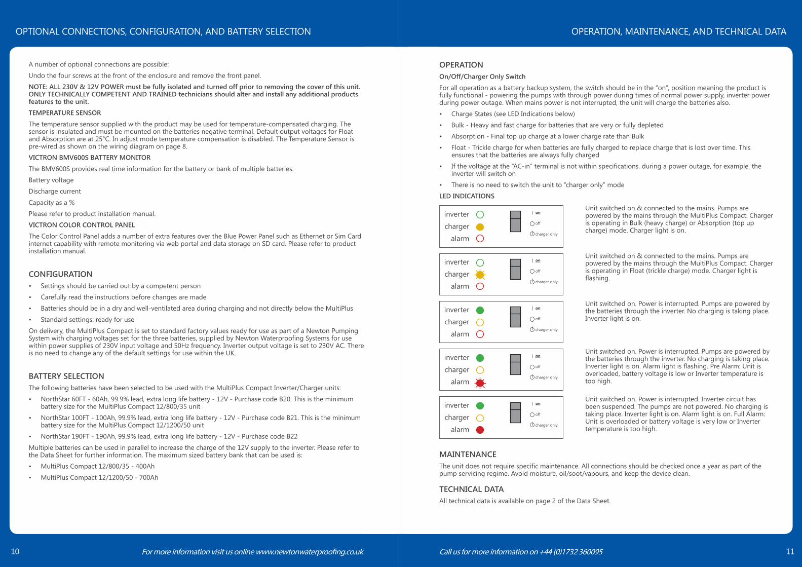
OPERATIONOn/Off/Charger Only Switch
For all operation as a battery backup system, the switch should be in the “on”, position meaning the product is fully functional - powering the pumps with through power during times of normal power supply, inverter power during power outage. When mains power is not interrupted, the unit will charge the batteries also.
• Charge States (see LED Indications below)
• Bulk - Heavy and fast charge for batteries that are very or fully depleted
• Absorption - Final top up charge at a lower charge rate than Bulk
• Float - Trickle charge for when batteries are fully charged to replace charge that is lost over time. This ensures that the batteries are always fully charged
• If the voltage at the “AC-in” terminal is not within specifications, during a power outage, for example, the inverter will switch on
• There is no need to switch the unit to “charger only” mode
LED INDICATIONS
MAINTENANCEThe unit does not require specific maintenance. All connections should be checked once a year as part of the pump servicing regime. Avoid moisture, oil/soot/vapours, and keep the device clean.
TECHNICAL DATAAll technical data is available on page 2 of the Data Sheet.
A number of optional connections are possible:
Undo the four screws at the front of the enclosure and remove the front panel.
NOTE: ALL 230V & 12V POWER must be fully isolated and turned off prior to removing the cover of this unit. ONLY TECHNICALLY COMPETENT AND TRAINED technicians should alter and install any additional products features to the unit.
TEMPERATURE SENSOR
The temperature sensor supplied with the product may be used for temperature-compensated charging. The sensor is insulated and must be mounted on the batteries negative terminal. Default output voltages for Float and Absorption are at 25°C. In adjust mode temperature compensation is disabled. The Temperature Sensor is pre-wired as shown on the wiring diagram on page 8.
VICTRON BMV600S BATTERY MONITOR
The BMV600S provides real time information for the battery or bank of multiple batteries:
Battery voltage
Discharge current
Capacity as a %
Please refer to product installation manual.
VICTRON COLOR CONTROL PANEL
The Color Control Panel adds a number of extra features over the Blue Power Panel such as Ethernet or Sim Card internet capability with remote monitoring via web portal and data storage on SD card. Please refer to product installation manual.
CONFIGURATION• Settings should be carried out by a competent person
• Carefully read the instructions before changes are made
• Batteries should be in a dry and well-ventilated area during charging and not directly below the MultiPlus
• Standard settings: ready for use
On delivery, the MultiPlus Compact is set to standard factory values ready for use as part of a Newton Pumping System with charging voltages set for the three batteries, supplied by Newton Waterproofing Systems for use within power supplies of 230V input voltage and 50Hz frequency. Inverter output voltage is set to 230V AC. There is no need to change any of the default settings for use within the UK.
BATTERY SELECTIONThe following batteries have been selected to be used with the MultiPlus Compact Inverter/Charger units:
• NorthStar 60FT - 60Ah, 99.9% lead, extra long life battery - 12V - Purchase code B20. This is the minimum battery size for the MultiPlus Compact 12/800/35 unit
• NorthStar 100FT - 100Ah, 99.9% lead, extra long life battery - 12V - Purchase code B21. This is the minimum battery size for the MultiPlus Compact 12/1200/50 unit
• NorthStar 190FT - 190Ah, 99.9% lead, extra long life battery - 12V - Purchase code B22
Multiple batteries can be used in parallel to increase the charge of the 12V supply to the inverter. Please refer to the Data Sheet for further information. The maximum sized battery bank that can be used is:
• MultiPlus Compact 12/800/35 - 400Ah
• MultiPlus Compact 12/1200/50 - 700Ah
inverter
charger
alarm
on
off
charger only
Unit switched on & connected to the mains. Pumps are powered by the mains through the MultiPlus Compact. Charger is operating in Bulk (heavy charge) or Absorption (top up charge) mode. Charger light is on.
inverter
charger
alarm
on
off
charger only
Unit switched on & connected to the mains. Pumps are powered by the mains through the MultiPlus Compact. Charger is operating in Float (trickle charge) mode. Charger light is flashing.
inverter
charger
alarm
on
off
charger only
Unit switched on. Power is interrupted. Pumps are powered by the batteries through the inverter. No charging is taking place. Inverter light is on.
Unit switched on. Power is interrupted. Pumps are powered by the batteries through the inverter. No charging is taking place. Inverter light is on. Alarm light is flashing. Pre Alarm: Unit is overloaded, battery voltage is low or Inverter temperature is too high.
inverter
charger
alarm
on
off
charger only
Unit switched on. Power is interrupted. Inverter circuit has been suspended. The pumps are not powered. No charging is taking place. Inverter light is on. Alarm light is on. Full Alarm: Unit is overloaded or battery voltage is very low or Inverter temperature is too high.
inverter
charger
alarm
on
off
charger only
OPTIONAL CONNECTIONS, CONFIGURATION, AND BATTERY SELECTION OPERATION, MAINTENANCE, AND TECHNICAL DATA

“As part of our policy of continuous product improvement we reserve the right to change our specifications at any time”
Newton Waterproofing Systems Is A Trading Name Of
John Newton & Company Ltd.Newton House, 17-20 Sovereign Way
Tonbridge, Kent TN9 1RH
T: +44 (0)1732 360095E: [email protected]: www.newtonwaterproofing.co.uk
®
TROUBLESHOOTINGThe following table provides a quick reference of the more common faults. Disconnect the battery/batteries and pumping systems before diagnosing the fault. Consult Newton Waterproofing Systems if the fault cannot be resolved.
Problem Cause Solution
The inverter fails to operate
Processor in ‘no function mode’ Disconnect from mains. Switch off. Wait 4 seconds. Switch on again.
The charger is not functioning
The thermal breaker has tripped Reset the 16A thermal circuit breaker
The battery is not being fully charged
Defective battery connection Check the battery terminalsThe internal DC fuse is defective Damaged inverter. Requires engineer
repair.The battery is overcharged
Defective battery/batteries Replace battery/batteries


