Use Cases Identifying Use cases Creating Use Case Diagrams Style Guidelines General Diagramming Guidelines How to Draw Use Case Diagrams Diagram Guidelines General diagramming guidelines UML Activity diagram guidelines UML Class diagram guidelines UML Collaboration diagram guidelines UML Component diagram guidelines UML Deployment diagram guidelines UML Interface Guidelines UML Frame Guidelines UML Note Guidelines UML Package diagram guidelines UML Sequence diagram guidelines UML State machine diagram guidelines UML Stereotype Guidelines UML Use case diagram guidelines Reuse Opportunities System Use cases
Transcript
Use CasesIdentifying Use cases
Creating Use Case Diagrams
Style Guidelines
General Diagramming Guidelines
How to Draw Use Case Diagrams
Diagram Guidelines
General diagramming guidelines
UML Activity diagram guidelines
UML Class diagram guidelines
UML Collaboration diagram guidelines
UML Component diagram guidelines
UML Deployment diagram guidelines
UML Interface Guidelines
UML Frame Guidelines
UML Note Guidelines
UML Package diagram guidelines
UML Sequence diagram guidelines
UML State machine diagram guidelines
UML Stereotype Guidelines
UML Use case diagram guidelines
Reuse Opportunities
System Use cases
Use CasesPage 2 Of 69
What are Use Cases
A use case is a sequence of actions that provide a measurable value to an actor. Another way to look at it is a use case describes a way in which a real-world actor interacts with the system. In a system use case you include high-level implementation decisions. System use cases can be written in both an informal manner and a formal manner. Techniques for identifying use cases are discussed as well as how to remain agile when writing use cases.
Identifying Use Cases
How do you go about identifying potential use cases? Constantine and Lockwood (1999) suggest one way to identify essential use cases, or simply to identify use cases, is to identify potential services by asking your stakeholders the following questions from the point of view of the actors:
What are users in this role trying to accomplish? To fulfill this role, what do users need to be able to do? What are the main tasks of users in this role? What information do users in this role need to examine, create, or change? What do users in this role need to be informed of by the system? What do users in this role need to inform the system about?
For example, from the point-of-view of the Student actor, you may discover that students:
Enroll in, attend, drop, fail, and pass seminars. Need a list of available seminars. Need to determine basic information about a seminar, such as its description and its prerequisites. Obtain a copy of their transcript, their course schedules, and the fees due. Pay fees, pay late charges, receive reimbursements for dropped and cancelled courses, receive grants,
and receive student loans. Graduate from school or drop out of it. Need to be informed of changes in seminars, including room changes, time changes, and even
cancellations.
Remaining Agile
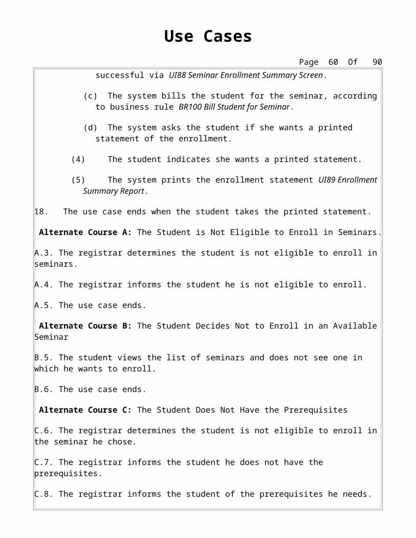
It is very easy for use case modeling to become un-agile. To prevent this from happening you need to focus on creating artifacts that are just barely good enough, they don’t need to be perfect. I’ve seen too many projects go astray because people thought that the requirements had to be worded perfectly. You’re not writing the Magna Carta!!!!!!! For example, in Figure 2 there are several imperfections, the alternate courses aren’t labeled in order (D appears after F and G) and the letters C and E aren’t used (they were at some point in the past but then were dropped). The use case isn’t perfect yet the world hasn’t ended. Yes I could invest time to fix these issues but what would the value be? Nothing. Always remember AM’s Maximize Stakeholder Investment principle and only do things that add value. Repeat after me: My use cases need to be just good enough. My use cases need to be just good enough. My use cases need to be just good enough. Why does this work? Because in an agile environment you’ll quickly move to writing code based on those requirements, you’ll discover that you don’t fully understand what is required, you’ll work closely with your stakeholder to do so, and you’ll build something that meets their actual needs. It’s software development, not documentation development.
Notice: This artifact description has been excerpted from The Object Primer 3rd Edition: Agile Modeling Driven Development with UML 2. The book goes into greater detail.
Many resources - books, magazine articles, and web sites - focus on how to work with the artifacts of the Unified Modeling Language (UML) as well as other modeling techniques. These resources introduce you to various modeling artifacts, describe a methodology for applying the artifacts in practice, or describe how to apply patterns and strategies for creating better models. Unfortunately few of these resources touch on the subject of style and when they do they rarely devote little space to it. This includes my own book, The Object Primer 3/e, which provides an excellent overview of UML artifacts (as well as a few others because the UML isn't sufficient for real-world development) and how to take them all the way to Java code and a relational database on the back end.
The focus of these pages is style. That's it.
It presents guidelines to improve the quality and readability of your software diagrams, making them easier to understand and to work with.
Included are guidelines for applying various modeling notations effectively, such as when to apply aggregation between two classes instead of association, but excluded are design patterns such as Strategy or Facade. Note that the primary focus of this site, at least at first, will be the UML, the industry standard for modeling systems using object-oriented and component-based systems. Data modelers may find www.agiledata.org to be of interest.
General Diagramming Guidelinesby Scott W. Ambler, Copyright 2002-2004
The guidelines presented here are applicable to all types of diagrams and are not specific to a single type of diagram. The terms bubbles, lines, and labels are used throughout:
Bubbles represent diagram elements such as class boxes, object boxes, use cases, and actors. Lines represent diagram elements such as associations, dependencies, and transitions between states. Labels represent diagram elements such as class names, association roles, and constraints.
Reorganize Large Diagrams Into Several Smaller Ones
Include Whitespace In Diagrams
Focus on Content First, Appearance Second
Cleanup to Rethink a Diagram
Organize Diagrams Left to Right, Top to Bottom
Set and Follow Effective Naming Conventions
Apply Common Domain Terminology in Names
Only Bring Language Naming Conventions Into Design Diagrams
Indicate Unknowns with a Question Marks
Consider Adding Color to Your Diagrams
1 Avoid Crossing Lines
When two lines cross on a diagram, such as two associations on a UML class diagram, the potential for misreading a diagram exists.
2 Crossing Lines Jump One Another
You can’t always avoid crossing lines, for example you cannot fully connect five bubbles on a two dimensional plan (try it and see). When you need to have two lines cross one of them should “hop” over the other, using the notation that you see in Figure 1 borrowed from electrical-wiring diagrams. This notation makes it clear that the lines are only crossing on your diagram and that they don’t connect in any way.
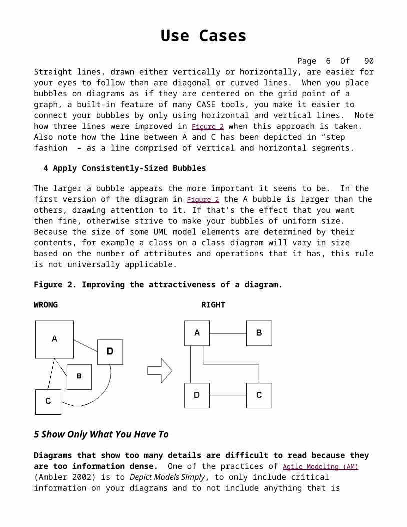
Straight lines, drawn either vertically or horizontally, are easier for your eyes to follow than are diagonal or curved lines. When you place bubbles on diagrams as if they are centered on the grid point of a graph, a built-in feature of many CASE tools, you make it easier to connect your bubbles by only using horizontal and vertical lines. Note how three lines were improved in Figure 2 when this approach is taken. Also note how the line between A and C has been depicted in “step fashion” – as a line comprised of vertical and horizontal segments.
4 Apply Consistently-Sized Bubbles
The larger a bubble appears the more important it seems to be. In the first version of the diagram in Figure 2 the A bubble is larger than the others, drawing attention to it. If that’s the effect that you want then fine, otherwise strive to make your bubbles of uniform size. Because the size of some UML model elements are determined by their contents, for example a class on a class diagram will vary in size based on the number of attributes and operations that it has, this rule is not universally applicable.
Figure 2. Improving the attractiveness of a diagram.
WRONG RIGHT
5 Show Only What You Have To
Diagrams that show too many details are difficult to read because they are too information dense. One of the practices of Agile Modeling (AM) (Ambler 2002) is to Depict Models Simply, to only include critical information on your diagrams and to not include anything that is extraneous. A simple model that shows the key features that you are trying to understand, perhaps a class model depicting the primary responsibilities of classes and the relationships between them, often proves to be sufficient. Yes, you could model all the scaffolding code that you will need to right, all the getter and setter operations that your coding standards tell you to use, but what value would that add? Very little.
6 Prefer Well-Known Notation Over Esoteric Notation
Furthermore, a diagram that uses a wide range of esoteric notation, instead of focusing on the 20% “kernel notation” that does 80% of the job, can be difficult to read. An expected improvement in the
UML 2.0 will be an explicit identification of that kernel notation to identify the primary notation that developers need to understand.
7 Reorganize Large Diagrams Into Several Smaller Ones
It is often better to have several diagrams showing various degrees of detail than one complex diagram that shows everything. A good rule of thumb is that a diagram shouldn’t have more than 9 bubbles on it, based on the 7 +/- 2 rule (Miller 1957), because there is a limit on the amount of information that someone can deal with at once. People can only comprehend small portions of information at a time, so your models had might as well reflect this fact. “Wallpaper” diagrams, particularly enterprise data models or UML class diagrams with a large number of classes, may look interesting but they’re too information dense to be effective.
When you are re-organizing a large diagram into several smaller ones you may choose to introduce a high-level package diagram (Fowler & Scott 1999) comprised solely of UML packages (the bubbles that look like a file folder). Each package would represent one of the smaller sub-models, and in a CASE tool would lead you directly to the sub-model.
8 Include Whitespace In Diagrams
Whitespace is the empty areas between modeling elements on your diagrams. In the first version of Figure 2 the bubbles were crowding each other, whereas the second version spread the bubbles out from one another thus improving the readability of the diagram. Observe that in the second version there is adequate space to add labels to the lines, if not we can separate the bubbles further until there is.
Using a CASE tool you will often be motivated to reduce the whitespace in a diagram to print it on a single page, perhaps because you want to refer to the diagram as you work. This is fine, but be aware that you’re reducing the usability of the diagram by doing so – sometimes it’s worth the effort to tape two pieces of paper together.
9 Focus on Content First, Appearance Second
There is always the danger of adding hours onto your modeling efforts by tweaking the way your diagrams look in your CASE tool by rearranging the layout of your bubbles and lines to improve the diagram’s readability. The best approach is to focus on the content of a diagram at first and only try to get it looking good in a rough sort of way – It doesn’t have to be perfect while you’re working on it. Once you’re satisfied that your diagram is accurate enough, and that you want to keep it, then invest appropriate time to make it look good. An advantage of this approach is that you don’t invest significant effort improving diagrams that you eventually end up discarding.
10 Cleanup to Rethink a Diagram
Rearranging your diagram to improve its readability is a relatively straightforward task, one that doesn’t require a lot of thinking to accomplish. As a result your mind tends to clear itself of whatever issues you were struggling with when you were modeling and you often discover as you are “cleaning up” a diagram a way to rework it to be more effective.
In Western culture people read left to right and top to bottom and therefore this is the approach that they will approach your diagrams. If there is starting point for reading a diagram, such as the initial state of a state chart diagram or the beginning of the flow of logic on a sequence diagram, then place it towards the top-left corner of your diagram and continue appropriately from there.
12 Set and Follow Effective Naming Conventions
This is one of the easiest things that you can do to ensure consistency within your models, and hence increase their readability. Specific conventions are suggested throughout these guidelines, however, it is important to recognize that because a modeling element may appear on several diagrams – classes can appear on UML Class diagrams, UML Collaboration diagrams, and UML Sequence diagrams – that you should strive to have a single and consistent source of naming conventions.
13 Apply Common Domain Terminology in Names
Your diagrams should use consistent and recognizable domain terminology, such as customer and order, whenever possible. This is particularly true for requirements and analysis-oriented diagrams that your project stakeholders are likely to be involved with.
14 Only Bring Language Naming Conventions into Design Diagrams
Because design diagrams should reflect implementation issues there is where language naming conventions, such as orderNumber for an attribute in Java, should be applied. Requirements and analysis-oriented diagrams should not reflect issues such as this.
15 Indicate Unknowns with a Question Mark
While you are modeling you often discover that you do not have complete information, this is particularly true when you are analyzing the domain because you initially didn’t get all of the information that you required from your project stakeholders. When you discover this to be the case you should try to track down the right answer, but if you cannot immediately do this then you should make a good guess and indicate that you are uncertain about what you have modeled. Figure 3 depicts a common way to do so, one that is not official UML, with its use of question marks. First, there is a note attached to the association between Professor and Seminar, you see that the modeler is questioning the multiplicity. Second, there is a question mark above the constraint on the wait listed association between Student and Seminar, likely and indication that the modeler isn’t sure that it really is a first in, first out (FIFO) list.
Use CasesPage 8 Of 69
16. Consider Adding Color to Your Diagrams
Coad, Lefebrvre, and DeLuca (1999) provide excellent advice in their book Java Modeling in Color With UML for improving the understandability of your diagrams by applying color to them. Your models are part of your communication interface with other developers, and just like user interfaces can be improved by the effective application of color so can your diagrams. In addition to applying UML stereotypes to your classes you can also apply color, perhaps controller classes are rendered in blue, business entity classes in green, and system classes in yellow. Other uses for color include indicating the implementation language of a class (e.g. blue for Java and red for C++) on a UML Class diagram, the development priority of a use case (e.g. red for phase 1, orange for phase 2, and yellow for future phases) on a UML Use Case diagram, or the target platform (e.g. blue for an application server, green for a client machine, and pink for a database server) for a software element on a UML Deployment diagram.
UML Class Diagram Guidelines
by Scott W. Ambler, Copyright 2002-2004
UML class diagrams show the classes of the system, their inter-relationships, and the operations and attributes of the classes. Class diagrams are typically used, although not all at once, to:
Explore domain concepts in the form of a domain model Analyze requirements in the form of a conceptual/analysis model Depict the detailed design of object-oriented or object-based software
A class model is comprised of one or more class diagrams and the supporting specifications that describe model elements including classes, relationships between classes, and interfaces.
Guidelines:
General Guidelines
Identify Responsibilities on Domain Class Diagrams Indicate Visibility Only On Design Models
Indicate Language-Dependent Visibility With Property Strings
Indicate Types On Design Models
Indicate Types On Analysis Models Only When The Type is an Actual Requirement
Design Class Diagrams Should Reflect Language Naming Conventions
Apply Composition When the Parts Share The Persistence Lifecycle With the Whole
Don’t Worry About Getting the Diamonds Right
1. General Guidelines
Because class diagrams are used for a variety of purposes – from understanding requirements to describing your detailed design – you will need to apply a different style in each circumstance. This section describes style guidelines pertaining to different types of class diagrams.
1.1 Identify Responsibilities on Domain Class Diagrams
When creating a domain class diagram, typically created as part of your requirements modeling efforts, you should focus on identifying responsibilities for classes instead of on specific attributes or operations. For example, the Invoice class is responsible for providing its total, but whether it maintains this as an attribute or simply calculates it at request time is a design decision that you’ll make later.
There is some disagreement as to this guideline, as it implies that you should be taking a responsibility-driven approach to development. Others, such as Craig Larman (2002), such a data-driven approach where you start domain models by only identifying data attributes resulting in a model that is little different than a logical data model. If you need to create a logical data model then do so, following Agile Modeling (AM)’s practice Apply the Right Artifact(s) (Ambler 2002), but if you want to create a UML Class diagram then you should consider the whole picture instead look at the whole picture and identify responsibilities.
1.2 Indicate Visibility Only On Design Models
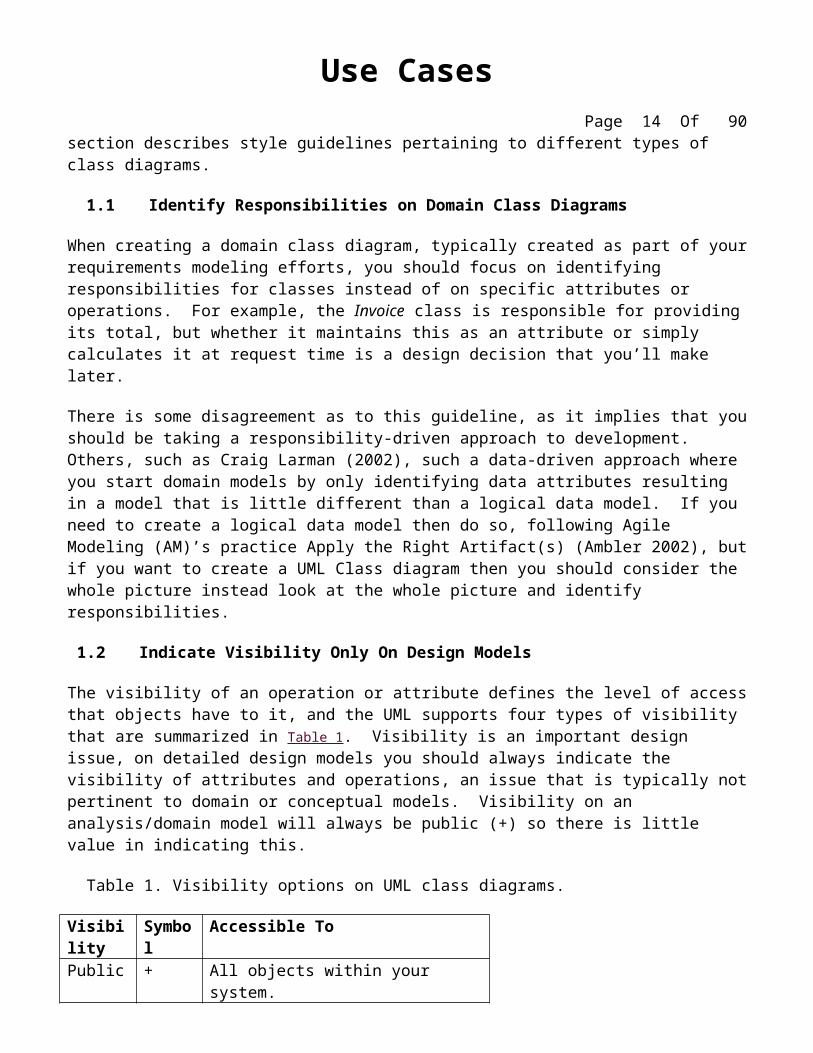
The visibility of an operation or attribute defines the level of access that objects have to it, and the UML supports four types of visibility that are summarized in Table 1. Visibility is an important design issue, on detailed design models you should always indicate the visibility of attributes and operations, an issue that is typically not pertinent to domain or conceptual models. Visibility on an analysis/domain model will always be public (+) so there is little value in indicating this.
Table 1. Visibility options on UML class diagrams.
Visibility Symbol Accessible To Public + All objects within your system.Protected # Instances of the implementing class and
its subclasses.Private - Instances of the implementing class.Package ~ Instances of classes within the same
1.3 Indicate Language-Dependent Visibility With Property Strings
If your implementation language includes non-UML supported visibilities, such as C++’s implementation visibility, then a property string should be used (Object Management Group 2001) as you see in Figure 1.
1.4 Indicate Types Only On Design Models
On greenfield projects where you are starting development from scratch the type, such as int or PhoneNumber, of an attribute, parameter, or return value is a design decision. Therefore it is appropriate to indicate types only on design models as you see in Figure 1.
1.5 Indicate Types On Analysis Models Only When The Type is an Actual Requirement
Sometimes the specific type of an attribute is a requirement. For example, your organization may have a standard definition for customer numbers that requires they be a nine digit number. Perhaps existing systems, such as a legacy database or a pre-defined data feed, constrains some data elements to a specific type or size. If this is the case you should indicate this information on your domain class model(s).
1.6 Design Class Diagrams Should Reflect Language Naming Conventions
Your design class models define the structure of your object source code, and therefore should reflect the naming conventions for the implementation language that you using. For example, in Figure 1 you see that the design version of the Order class uses names that conform to common Java programming conventions (Vermeulen et. al. 2000) such as placementDate and calculateTaxes().
Figure 1. Analysis and design versions of a class.
1.7 Model Association Classes On Analysis Diagrams
Association classes, also called link classes, are used to model associations that have methods and attributes. Figure 2 shows that association classes are depicted as class attached via a dashed line to an association – the association line, the class, and the dashed line are considered one symbol in the UML. Association classes are typically modeled during analysis and then refactored during design (Ambler 2001) because mainstream programming languages such as C++ and Java do not (yet) have native support for this concept.
Figure 2. Modeling association classes.
1.8 Do Not Name Associations That Have Association Classes
The name of the association class should adequately describe the association, therefore as you see in Figure 2 the association does not need an additional adornment indicating its name.
1.9 Center The Dashed Line of an Association Class
The dashed line connecting the class to the association path should clearly be connected to the path and not to either class or to any adornments of the association so it is clear what you mean. As you see in Figure 2 the easiest way to accomplish this is to center the dashed line on the association path.
2. Class Style Guidelines
A class is effectively a template from which objects are created (instantiated). Although in the real world Doug, Wayne, John, and Bill are all student objects we would model the class Student instead. Classes define attributes, information that is pertinent to their instances, and operations, functionality that the objects support. Classes will also realize interfaces (more on this later).
Note that you may need to soften some of the naming guidelines to reflect your implementation language or software purchased from a third-party vendor.
Class names should be based on commonly accepted terminology to make them easier to understand by others. For business classes this would include names based on domain terminology such as Customer, OrderItem, and Shipment and for technical classes names based on technical terminology such as MessageQueue, ErrorLogger, and PersistenceBroker.
2.2 Prefer Complete Singular Nouns for Class Names
Names such as Customer and PersistenceBroker are preferable to Cust and PBroker respectively because they are more descriptive and thus easier to understand. Furthermore, it is common practice to name classes as singular nouns such as Customer instead of Customers. Even if you have a class that does in fact represent several objects, such as an iterator (Gamma et. al. 1995) over a collection of customer objects, then a name such as CustomerIterator would be appropriate.
2.3 Name Operations with a Strong Verb
Operations implement the functionality of an object, therefore they should be named in a manner that effectively communicates that functionality. Table 2 lists operation names for analysis class diagrams as well as for design class diagrams – the assumption is that your implementation language follows Java naming conventions (Vermeulen et. al. 2000) – indicating how the operation name has been improved in each case.
Table 2. Example names for operations.
Initial Name Good Analysis Name
Good Design NameIssue
Open Acc Open Account openAccount() An abbreviation was replaced with the full word to make it clear what is meant.
Mailing Label PrintPrint Mailing Label
printMailingLabel() The verb was moved to the beginning of the name to make it active.
purchaseparkingpass() Purchase Parking Pass
purchaseParkingPass() Mixed case was applied to increase the readability of the design-level name.
Save the Object Save save() The name was shortened because the term “TheObject” did not add any value.
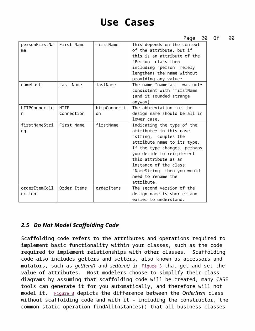
Like classes and operations you should use full descriptions to name your attributes so that it is obvious what the attribute represents. Table 3 suggests a Java-based naming convention for analysis names that in the format Attribute Name, although attribute name and Attribute name formats are also fine if applied consistently. Table 3 also suggests design names that take an attributeName format, although the attribute_name format is just as popular depending on your implementation language.
Table 3. Example names for attributes.
Initial Name Good Analysis Name
Good Design Name
Issue
fName First Name firstName Do not use abbreviations in attribute names.
firstnameFirst Name firstName
Capitalizing the second word of the design name makes the attribute name easier to read.
personFirstName First Name firstName This depends on the context of the attribute, but if this is an attribute of the “Person” class then including “person” merely lengthens the name without providing any value.
nameLast Last Name lastName The name “nameLast” was not consistent with “firstName” (and it sounded strange anyway).
hTTPConnection HTTP Connection httpConnection The abbreviation for the design name should be all in lower case.
firstNameString First Name firstName Indicating the type of the attribute, in this case “string,” couples the attribute name to its type. If the type changes, perhaps you decide to reimplement this attribute as an instance of the class “NameString” then you would need to rename the attribute.
orderItemCollection Order Items orderItems The second version of the design name is shorter and easier to understand.
2.5 Do Not Model Scaffolding Code
Scaffolding code refers to the attributes and operations required to implement basic functionality within your classes, such as the code required to implement relationships with other classes. Scaffolding code also includes getters and setters, also known as accessors and mutators, such as getItem() and setItem() in Figure 3 that get and set the value of attributes. Most modelers choose to simplify their class diagrams by assuming that scaffolding code will be created, many CASE tools can generate it for you automatically, and therefore will not model it. Figure 3 depicts the difference between the OrderItem class
without scaffolding code and with it – including the constructor, the common static operation findAllInstances() that all business classes implement (in this system), and the attributes item and order and their corresponding getters and setters to maintain its relationships with the Order class and Item class respectively.
Figure 3. The OrderItem class with and without scaffolding code.
2.6 Never Show Classes With Just Two Compartments
It is allowable within the UML to have a class with one or more compartments. Although compartments may appear in any order, traditionally the top-most compartment indicates the name of the class and any information pertinent to the class as a whole (such as a stereotype), the second optional compartment typically lists the attributes, and the third optional compartment typically lists the operations. Other “non-standard” compartments may be added to the class to provide information such as lists of exceptions thrown or notes pertaining to the class. Because naming conventions for attributes and operations are similar, see below, and because people new to object development may confuse the two concepts, it isn’t advisable to have classes with just two compartments (one for the class name and one listing either attributes or operations) because it can become confusing for your readers. If you need to, include a blank compartment as a placeholder as you see with the Student class in Figure 2.
2.7 Label Uncommon Class Compartments
If you do intend to include a class compartment that isn’t one of the standard three – class name, attribute list, operations list – then include a descriptive label such as “Exceptions” or “Constraints” centered at the top of the compartment as you see with the Student class in Figure 2.
2.8 Include an Ellipsis ( … ) At The End of Incomplete Lists
You know that the list of attributes of the Student Class of Figure 2 is incomplete because the modeler included an ellipsis at the end of the list – without this ellipsis there would be no indication that there is more to the class than what is currently shown.
2.9 List Static Operations/Attributes Before Instance Operations/Attributes
In most classes static operations and attributes will be outnumbered by instance operations and attributes. Furthermore, static operations and attributes typically deal with early aspects of a class’s lifecycle, such as the creation of objects or finding existing instances of the classes. In other words, when you are working with a class you often start with statics, therefore it makes sense to list them first in their appropriate compartments as you see in Figure 3 (statics are underlined).
2.10 List Operations/Attributes in Decreasing Visibility
The greater the visibility of an operation or attribute the greater the chance that someone else will be interested in it. For example, because public operations are accessible to a greater audience than protected operations, there is a greater likelihood that greater interest exists in public operations. Therefore, list your attributes and operations in order of decreasing visibility so they appear in order of importance. As you can see in Figure 3 the operations and attributes of the OrderItem class are then listed alphabetically for each level of visibility.
2.11 For Parameters That Are Objects, Only List Their Type
As you see in Figure 3 operation signatures can become quite long, extending the size of the class symbol. To save space you can forgo listing the types of objects that are passed as parameters to operations. For example, you see that Figure 3 lists calculateTaxes(Country, State) instead of calculateTaxes(country: Country, state: State), saving a little bit of room.
2.12 Develop Consistent Method Signatures
The greater the consistency within your designs the easier they are to learn and to understand. First, operations names should be consistent with one another – for example in Figure 3 all finder operations start with the text find. Second, parameter names should also be consistent with one another. For example, parameter names such as theFirstName, firstName, and firstNm are not consistent with one another nor are firstName, aPhoneNumber, and theStudentNumber. Pick one naming style for your parameters and stick to it. Third, the order of parameters should also be consistent. For example, the methods
doSomething(securityToken, startDate) and doSomethingElse(studentNumber, securityToken) could be made more consistent by always passing securityToken as either the first or the last parameter.
2.13 Avoid Stereotypes Implied By Language Naming Conventions
The Unified Modeling Language (Rumbaugh, Jacobson, and Booch, 1999) allows for stereotypes to be applied to operations. In Figure 3 I applied the stereotype <<constructor>> to the operation OrderItem(Order) but that information is redundant because the name of the operation implies that it’s a constructor, at least if the implementation language is Java or C++. Furthermore, you should avoid stereotypes such as <<getter>> and <<setter>> for similar reasons – the names getAttributeName() and setAttributeName() indicate the type of operations you’re dealing with.
2.14 Indicate Exceptions In An Operation’s Property String
Some languages, such as Java, allow operations to throw exceptions to indicate that an error condition has occurred. Exceptions can be indicated with a UML property string, an example of which is shown in Figure 4.
Figure 4. Indicating the exceptions thrown by an operation.
3. InterfacesAn interface is a collection of operation signature and/or attribute definitions that ideally defines a cohesive set of behaviors. Interfaces are implemented, “realized” in UML parlance, by classes and components – to realize an interface a class or component must implement the operations and attributes defined by the interface. Any given class or component may implement zero or more interfaces and one or more classes or components can implement the same interface.
3.1 Interface Definitions Must Reflect Implementation Language Constraints
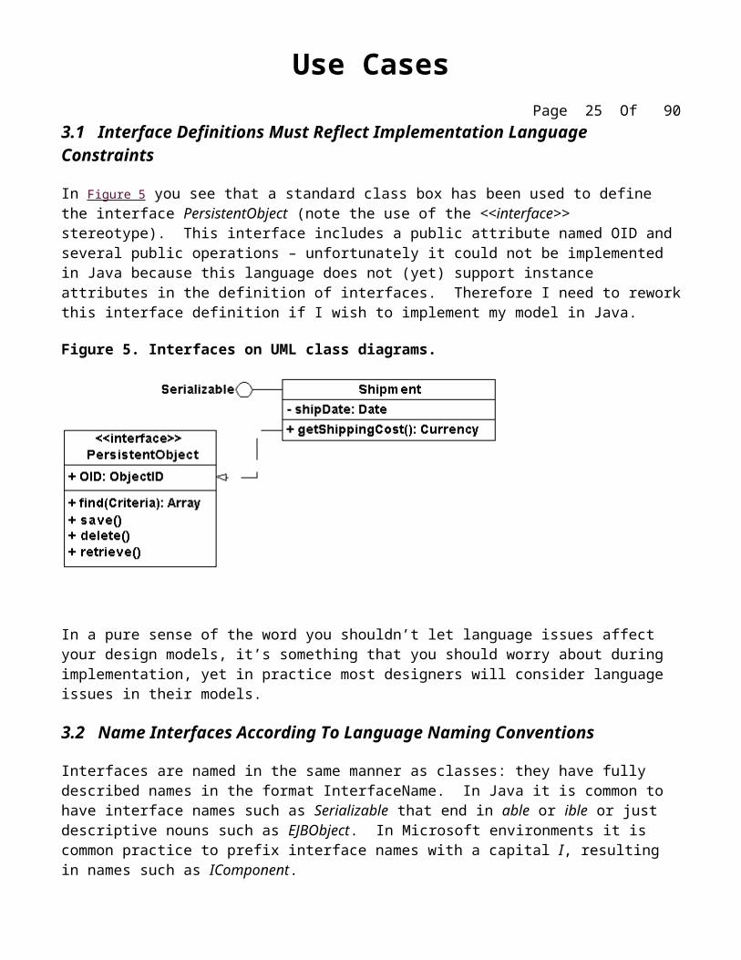
In Figure 5 you see that a standard class box has been used to define the interface PersistentObject (note the use of the <<interface>> stereotype). This interface includes a public attribute named OID and several public operations – unfortunately it could not be implemented in Java because this language does not (yet) support instance attributes in the definition of interfaces. Therefore I need to rework this interface definition if I wish to implement my model in Java.
Figure 5. Interfaces on UML class diagrams.
In a pure sense of the word you shouldn’t let language issues affect your design models, it’s something that you should worry about during implementation, yet in practice most designers will consider language issues in their models.
3.2 Name Interfaces According To Language Naming Conventions
Interfaces are named in the same manner as classes: they have fully described names in the format InterfaceName. In Java it is common to have interface names such as Serializable that end in able or ible or just descriptive nouns such as EJBObject. In Microsoft environments it is common practice to prefix interface names with a capital I, resulting in names such as IComponent.
3.3 Apply “Lollipop” Notation To Indicate That A Class Realizes an Interface
As you see in Figure 5 there are two ways to indicate that a class or component implements an interface: the lollipop notation used with the Serializable interface and the realization line (the dashed line with a closed arrowhead) used to show with the PersistentObject interface. The lollipop notation is preferred because it is visually compact – the class box and realization line approach tend to clutter your diagrams.
3.4 Define Interfaces Separately From Your Classes
To reduce clutter you should define interfaces separately from classes, either in another diagram specifically for interface definitions or simply on one edge of your class diagram.
3.5 Do Not Model the Operations and Attributes of an Interface in Your Classes
In Figure 5 you’ll notice that the Shipment class does not include the attributes or operations defined by the two interfaces that it realizes – that information would be redundant because it is already contained within the interface definitions.
3.6 Consider an Interface to Be a Contract
When you model that classifier realizes an interface you are effectively committing to implementing that interface in the classifier, in other words the interface acts as a contract that the classifier fulfills. Because many classifiers may implement a single interface you should think seriously before modifying the definition of an interface. AM’s Formalize Contract Models (Ambler 2002) suggests that you negotiate any changes to a contract model, in this case the interface specification, with the users of that interface before making any changes.
4. Relationship GuidelinesFor ease of discussion the term relationships shall include all UML concepts such as associations, aggregation, composition, dependencies, inheritance, and realizations – in other words, if it’s a line on a UML class diagram we’ll consider it a relationship.
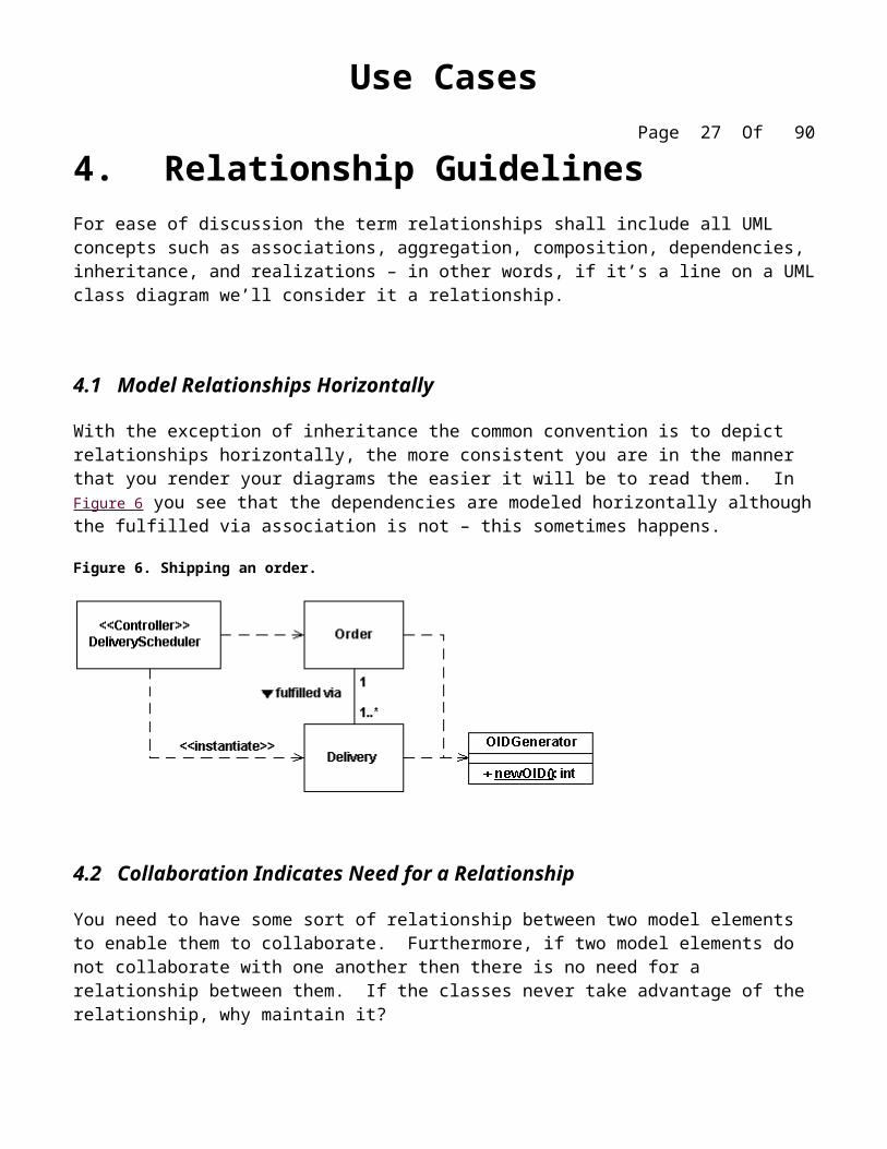
4.1 Model Relationships Horizontally
With the exception of inheritance the common convention is to depict relationships horizontally, the more consistent you are in the manner that you render your diagrams the easier it will be to read them. In Figure 6 you see that the dependencies are modeled horizontally although the fulfilled via association is not – this sometimes happens.
4.2 Collaboration Indicates Need for a Relationship
You need to have some sort of relationship between two model elements to enable them to collaborate. Furthermore, if two model elements do not collaborate with one another then there is no need for a relationship between them. If the classes never take advantage of the relationship, why maintain it?
4.3 Model a Dependency When The Relationship is Transitory
Transitory relationships, relationships that are not persistent, occur when one or more of the items involved in a relationship is either transitory itself or a class. In Figure 6 you see that there is a dependency between DeliveryScheduler and Order – DeliveryScheduler is a transitory class, one that you do not persist to your database, and therefore there is no need to persist any relationship between the scheduler and the order objects that it interacts with. The relationship between DeliveryScheduler and Delivery is also a dependency, even though DeliveryScheduler creates Delivery objects, for the same reason.
In Figure 6 instances of Delivery interact with OIDGenerator to obtain a new integer value to act as an object identifier (OID) to be used as a primary key value in a relational database (Ambler, 2001). You know that Delivery objects are interacting with OIDGenerator and not an instance of it because the operation is static. Therefore, because there is no permanent relationship to be recorded and therefore a dependency is sufficient.
4.4 Depict Similar Relationships Involving A Common Class As A Tree
In Figure 6 you see that both Delivery and Order have a dependency on OIDGenerator. Note how the two dependencies are drawn in combination in “tree configuration”, instead of as two separate lines, to reduce clutter in the diagram. You can take this approach with any type of relationship, it is quite common with inheritance hierarchies (as you see in Figure 9), as long as the relationship ends that you are combining are identical. For example, in Figure 7 you see that OrderItem is involved with two separate relationships. Unfortunately the multiplicities are different for each, one is 1..* and the other 0..* so you
can’t combine the two into a tree structure – had they been the same you could have, even though one relationship is aggregation and the other association.
Note that there is a danger that you may be motivated not to change a relationship when you really should in order to preserve the tree arrangement.
4.5 Always Indicate the Multiplicity
For each class involved in a relationship there will always be a multiplicity for it. When the multiplicity is one and one only, for example with aggregation and composition it is often common for the part to be involved only with one whole, many modelers will not model the “1" beside the diamond. I believe that this is a mistake, and as you see in Figure 7 I will indicate the multiplicity in this case. If the multiplicity is "1" then indicate it as such so your readers know that you’ve considered the multiplicity. Table 4 summarizes the multiplicity indicators that you will see on UML class diagrams.
Figure 7. Modeling an order.
Table 4. UML multiplicity indicators.
Indicator Meaning 0..1 Zero or one1 One only0..* Zero or more1..* One or moren Only n (where n > 1)* Many 0..n Zero to n (where n > 1)1..n One to n (where n > 1)n..m Where n & m both > 1n..* n or more, where n > 1
You should avoid the use of "*" to indicate multiplicity on a UML Class diagram because your reader can never be sure if you really meant "0..*" or "1..*".
4.7 Replace Relationships By Indicating Attribute Types
In Figure 7 you see that Customer has a shippingAddress attribute of type Address – part of the scaffolding code to maintain the association between customer objects and address objects. This simplifies the diagram because it visually replaces a class box and association.
Note that this partially contradicts theDo Not Model Scaffolding Code guideline. You will need to judge which guideline to follow, the critical issue being which one will improve your diagram the most given your situation.
4.8 Do Not Model Implied Relationships
In Figure 7 there is an implied association between Item and Order, items appear on orders, but it was not modeled. A mistake? No, the association is implied through OrderItem, orders are made up of order items which in turn are described by items. These two relationships, when taken together, implement the implied association that students take (enroll in) seminars. If you model this implied association not only do you clutter your diagram you also run the risk that somebody will develop the additional code to maintain it. If you don’t intend to maintain the actual relationship, e.g you aren’t going to write the scaffolding code, then don’t model it.
4.9 Do Not Model Every Single Dependency
A common mistake made on detailed design diagram is to model every single dependency between classes, quickly cluttering your diagrams with additional lines. A better approach is to model a dependency between classes only if doing so adds to the communication value of your diagram – as always you should strive to follow Agile Modeling (AM)’s practice Depict Models Simply (Ambler, 2002).
It is common convention to center the name of an association above an association path, as you see in Figure 7 with the describes association between Order and Item, or beside the path as with the fulfilled via association between Order and Delivery.
5.2 Write Concise Association Names In Active Voice
The name of an association, which is optional although highly recommended, is typically one or two descriptive words. If you find that an association name is wordy think about it from the other direction – for example, the places name of Figure 7 is concise when read from right-to-left but would be wordy if written from the left-to-right perspective (e.g. “is placed by”). Furthermore, places is written in active voice instead of passive voice, making it clearer to the reader .
5.3 Indicate Directionality To Clarify An Association Name
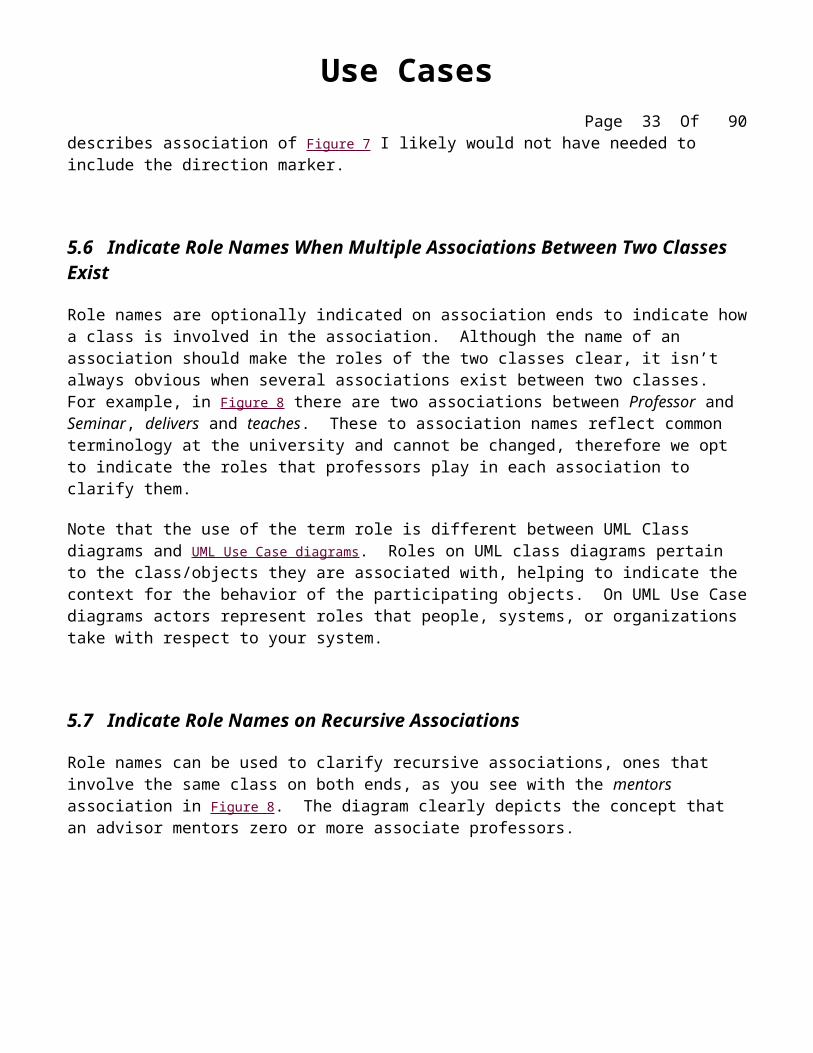
When it isn’t clear in which direction the name of an association should be read you can indicate the direction with a filled triangle as you see in Figure 7 between OrderItem and Item. This marker indicates that the association should be read as "an item describes an order item" instead of "an order item describes an item." It is also quite common to indicate the directionality on recursive associations, where the association starts and ends on the same class, such as mentors in Figure 8.
Better yet, when an association name isn’t clear then you should consider rewording it or potentially even renaming the classes.
Figure 8. Professors and seminars.
5.4 Name Unidirectional Associations In The Same Direction
The reading direction of an association name should be the same as that of the unidirectional association – this is basically a consistency issue.
Because people in Western societies read from left-to-right it is common practice to word association names so that they make sense when read from left-to-right. Had I followed this guidelines with the describes association of Figure 7 I likely would not have needed to include the direction marker.
5.6 Indicate Role Names When Multiple Associations Between Two Classes Exist
Role names are optionally indicated on association ends to indicate how a class is involved in the association. Although the name of an association should make the roles of the two classes clear, it isn’t always obvious when several associations exist between two classes. For example, in Figure 8 there are two associations between Professor and Seminar, delivers and teaches. These to association names reflect common terminology at the university and cannot be changed, therefore we opt to indicate the roles that professors play in each association to clarify them.
Note that the use of the term role is different between UML Class diagrams and UML Use Case diagrams. Roles on UML class diagrams pertain to the class/objects they are associated with, helping to indicate the context for the behavior of the participating objects. On UML Use Case diagrams actors represent roles that people, systems, or organizations take with respect to your system.
5.7 Indicate Role Names on Recursive Associations
Role names can be used to clarify recursive associations, ones that involve the same class on both ends, as you see with the mentors association in Figure 8. The diagram clearly depicts the concept that an advisor mentors zero or more associate professors.
5.8 Make Associations Bi-Directional Only When Collaboration Occurs In Both Directions
The lives at association of Figure 9 is uni-directional – a person object knows its address but an address object does not know who lives at it. Within this domain there is no requirement to traverse the association from Address to Person, therefore the association does not need to be bi-directional (two way). This reduces the code that needs to be written and tested within the address class because the scaffolding to maintain the association to Person isn’t required.
5.9 Redraw Inherited Associations Only When Something Changes
An interesting aspect of Figure 9 is the association between Person and Address. First, this association was pushed up to Person because Professor, Student, and Alumnus all had a lives at association with Address. Because associations are implemented by the combination of attributes and operations, both of which are inherited, the implication is that associations are inherited by implication. If the nature of the association doesn’t change, for example both students and professors live at only one address, then we don’t have any reason to redraw the association. However, because we track multiple addresses for Alumnus the relationship did need to be redrawn between Alumnus and Address.
5.10 Question Multiplicities Involving Minimums And Maximums
The problem with minimums and maximums is that they change over time. For example today you may have a business rule that states that an Alumnus has either one or two addresses that the university tracks, motivating you to model the multiplicity as 1..2 as depicted in Figure 9. However, if you build your system to reflect this rule when the rule changes you may find that you have significant rework to perform. In most object languages it is easier to implement a 1..* multiplicity, or better yet a 0..* multiplicity, because you don’t have to check the size of the collection maintaining the association. Providing greater flexibility with less code seems good to me.
6. Inheritance GuidelinesInheritance models “is a” and “is like” relationships, enabling you to easily reuse existing data and code. When “A” inherits from “B” we say that “A” is the subclass of “B” and that “B” is the superclass of “A.”
Furthermore, we say that we have “pure inheritance” when “A” inherits all of the attributes and methods of “B.” The UML modeling notation for inheritance is a line with a closed arrowhead pointing from the subclass to the superclass.
6.1 Apply the Sentence Rule For Inheritance
One of the following sentences should make sense: “A subclass IS A superclass” or “A subclass IS LIKE A superclass.” For example, it makes sense to say that a student is a person and a dragon is like a bird. It does not make sense to say a student is an address or is like an address, so the class Student likely should not inherit from Address – association is likely a better option, as you see in Figure 9. If it does not make sense to say that "the subclass is a superclass" or at least "the subclass is like the superclass" then you are likely misapplying inheritance.
Implementation inheritance, often called convenience inheritance, often occurs when the sentence fails yet inheritance is used anyway. This is particularly common when developers want to take short cuts and have business classes inherit system or persistence behaviors, instead of accessing these services through collaboration.
6.2 Place Subclasses Below Superclasses
It is common convention to place a subclass, such as Student in Figure 9, below its superclass – Person in this case.
6.3 Beware of Data-Based Inheritance
If the only reason why two classes inherit from each other is because they share common data attributes it indicates one of two things: you have either missed some common behavior (this is likely if the sentence rule applies) or you should have applied association instead.
6.4 A Subclass Should Inherit Everything
A subclass should inherit all of the attributes and methods of its superclass, and therefore all of its relationships as well – a concept called pure inheritance. The advantage of pure inheritance is that you only have to understand what a subclass inherits, and not what it does not inherit. While this sounds trivial, in a deep class hierarchy it makes it a lot easier if you only need to understand what each class adds, and not what it takes away. Note that this contradicts the Redraw Inherited Associations Only When Something Changes guideline so you’ll need to decide accordingly.
7. Aggregation and Composition GuidelinesSometimes an object is made up of other objects. For example, an airplane is made up of a fuselage, wings, engines, landing gear, flaps, and so on. A delivery shipment contains one or more packages. A team consists of two or more employees. These are all examples of the concept of aggregation, which represents “is part of” relationships. An engine is part of a plane, a package is part of a shipment, and an employee is part of a team. Aggregation is a specialization of association, specifying a whole-part relationship between two objects. Composition is a stronger form of aggregation where the whole and parts have coincident lifetimes, and it is very common for the whole to manage the lifecycle of its parts. From a stylistic point of view, because aggregation and composition are both specializations of association the guidelines for associations apply.
7.1 Apply the Sentence Rule for Aggregation
It should make sense to say “the part IS PART OF the whole.” For example, in Figure 10 it makes sense to say that a course is part of a program or that a component is part of an airplane. However, it does not make sense to say that a team is part of an airplane or an airplane is part of a team – it does make sense to say that a team builds airplanes, an indication that association is applicable.
Figure 10. Examples of aggregation and composition.
7.2 You Should Be Interested In Both The Whole And The Part
For aggregation and composition you should be interested in both the whole and the part separately – both the whole and the part should exhibit behavior that is of value to your system. For example, you could
model the fact that my watch has hands on it but if this fact isn't pertinent to your system (perhaps you sell watches but not watch parts) then there is no value in modeling watch hands.
7.3 Depict the Whole to the Left of the Part
It is common convention to draw the whole, such as Team and Airplane, to the left of the part, Employee and Component as you see in Figure 10 respectively.
7.4 Apply Composition to Aggregates of Physical Items
A good rule of thumb is that composition is applicable whenever aggregation is AND both classes represent physical items. For example, in Figure 10 you see that composition is used between Airplane and Component whereas aggregation is used between Team and Employee – airplanes and components are both physical items whereas teams are not.
7.5 Apply Composition When the Parts Share The Persistence Lifecycle With the Whole
A good rule of thumb is that if the lifecycle of the parts is the same as the whole, if they’re read in at the same time, if they’re saved at the same time, if they’re deleted at the same time, then composition is likely applicable.
7.6 Don’t Worry About Getting the Diamonds Right
When deciding whether to use aggregation or composition over association, Craig Larman (2001) says it best: If in doubt, leave it out. The reality is that many modelers will agonize over when to use aggregation when the reality is that there is very little difference between association, aggregation, and composition at the coding level.
UML Collaboration Diagramming Guidelinesby Scott W. Ambler, Copyright 2002-2004
UML collaboration/communication diagrams (Object Management Group 2001) like UML sequence diagrams, are used to explore the dynamic nature of your software. Collaboration diagrams show the message flow between objects in an OO application, and also imply the basic associations (relationships) between classes. Collaboration diagrams are often used to:
Provide a birds-eye view of a collection of collaborating objects, particularly within a real-time environment. Allocate functionality to classes by exploring the behavioral aspects of a system. Model the logic of the implementation of a complex operation, particularly one that interacts with a large
number of other objects. Explore the roles that objects take within a system, as well as the different relationships they are involved
Use Instance-Level Diagrams To Explore Object Design Issues Use Specification-Level Diagrams to Explore Roles
Collaboration Diagrams Do Not Model Process Flow
When Sequence Is Important Use a Sequence Diagram
Apply Sequence Diagram Guidelines To Instance-Level Collaboration Diagrams
Messages
Indicate a Return Value Only When It Isn’t Clear Indicate Parameters Only When They Aren’t Clear
Depict An Arrow For Each Message
Consolidate Getter Invocations
Indicate Concurrent Threads With Letters
Links
Model “Bare” Links On Instance-Level Collaboration Diagrams Show Role-Pertinent Information on Specification-Level Diagrams
Indicate Navigability Sparingly
Links Should Be Consistent Static Relationships
1. General
1.1 Use Instance-Level Diagrams To Explore Object Design Issues
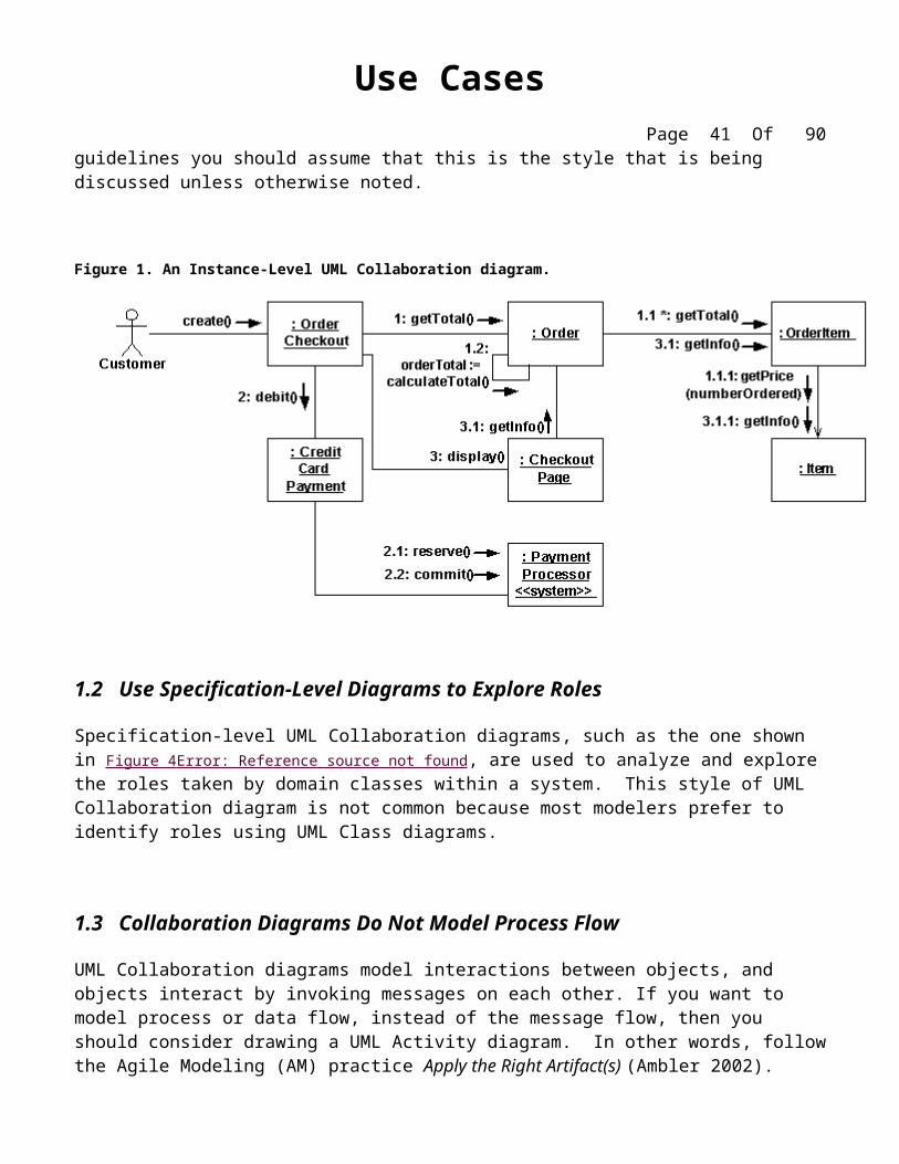
Instance-level UML Collaboration diagrams, such as the one shown in Error: Reference source not found, depict interactions between objects (instances). Instance-level diagrams are typically created to explore the internal design of object-oriented software. This by far is the most common style of UML Collaboration diagram, and throughout these guidelines you should assume that this is the style that is being discussed unless otherwise noted.
Figure 1. An Instance-Level UML Collaboration diagram.
1.2 Use Specification-Level Diagrams to Explore Roles
Specification-level UML Collaboration diagrams, such as the one shown in Figure 4 Error: Reference source not found, are used to analyze and explore the roles taken by domain classes within a system. This style of UML Collaboration diagram is not common because most modelers prefer to identify roles using UML Class diagrams.
1.3 Collaboration Diagrams Do Not Model Process Flow
UML Collaboration diagrams model interactions between objects, and objects interact by invoking messages on each other. If you want to model process or data flow, instead of the message flow, then you should consider drawing a UML Activity diagram. In other words, follow the Agile Modeling (AM) practice Apply the Right Artifact(s) (Ambler 2002).
1.4 When Sequence Is Important Use a Sequence Diagram
Although it is possible to indicate the sequence of message sends on a collaboration diagram, as you see in Error: Reference source not foundError: Reference source not found, the need to do this is a good indication that you should consider creating a UML Sequence diagram instead. Once again, follow the AM practice Apply the Right Artifact(s).
1.5 Apply Sequence Diagram Guidelines To Instance-Level Collaboration Diagrams
Because UML Collaboration diagrams depict an alternate view of the same information as UML Sequence diagrams much of the same style advice applies. The following lists of guidelines, originally presented for UML Sequence diagrams, are applicable to collaboration diagrams:
Name Objects When Your Reference Them In Messages Name Objects When Several of the Same Type Exist Apply Textual Stereotypes Consistently Apply Visual Stereotypes Sparingly Focus on Critical Interactions Prefer Names Over Types for Parameters Indicate Types as Parameter Placeholders Do Not Model a Return Value When it is Obvious What is Being Returned Model a Return Value Only When You Need to Refer to it Elsewhere Model Return Values as Part of a Method Invocation Indicate Types as Return Value Placeholders
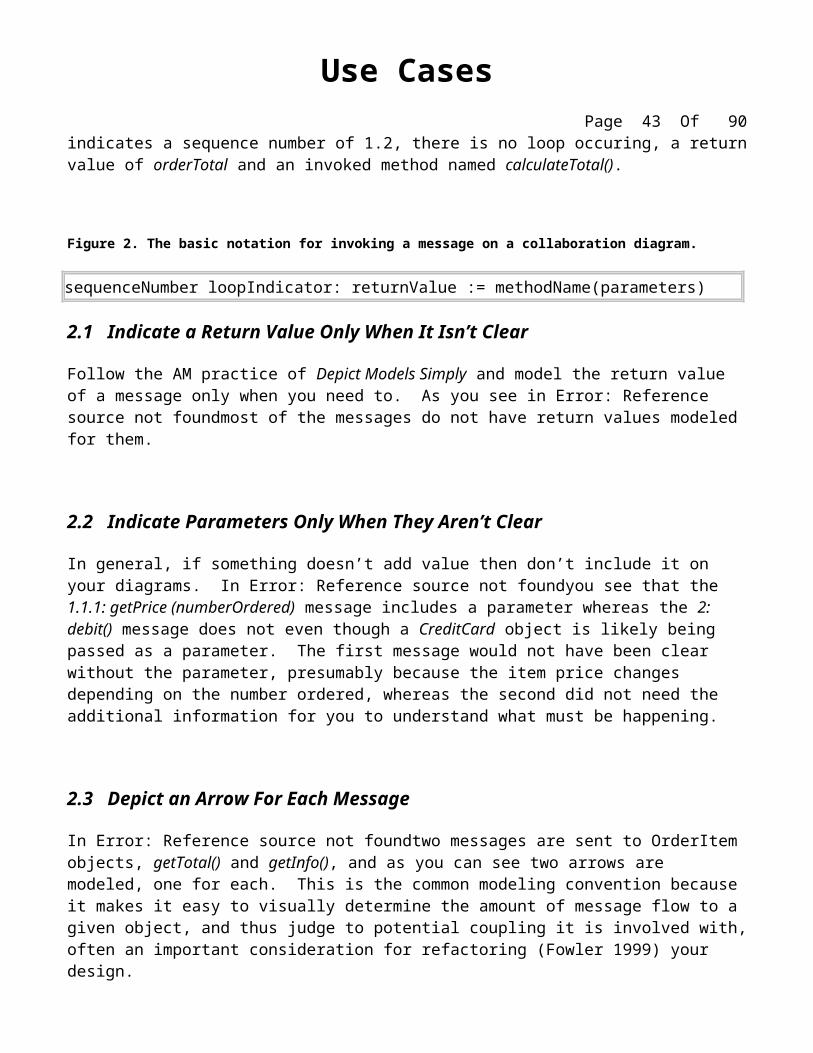
2. MessagesError: Reference source not foundpresents the notation for invoking messages on UML Collaboration diagrams. For example in Error: Reference source not foundthe message 1.2: orderTotal := calculateTotal() indicates a sequence number of 1.2, there is no loop occuring, a return value of orderTotal and an invoked method named calculateTotal().
Figure 2. The basic notation for invoking a message on a collaboration diagram.
2.1 Indicate a Return Value Only When It Isn’t Clear
Follow the AM practice of Depict Models Simply and model the return value of a message only when you need to. As you see in Error: Reference source not foundmost of the messages do not have return values modeled for them.
Use CasesPage 33 Of 69
2.2 Indicate Parameters Only When They Aren’t Clear
In general, if something doesn’t add value then don’t include it on your diagrams. In Error: Reference source not foundyou see that the 1.1.1: getPrice (numberOrdered) message includes a parameter whereas the 2: debit() message does not even though a CreditCard object is likely being passed as a parameter. The first message would not have been clear without the parameter, presumably because the item price changes depending on the number ordered, whereas the second did not need the additional information for you to understand what must be happening.
2.3 Depict an Arrow For Each Message
In Error: Reference source not foundtwo messages are sent to OrderItem objects, getTotal() and getInfo(), and as you can see two arrows are modeled, one for each. This is the common modeling convention because it makes it easy to visually determine the amount of message flow to a given object, and thus judge to potential coupling it is involved with, often an important consideration for refactoring (Fowler 1999) your design.
2.4 Consolidate Getter Invocations
It is good design practice (Ambler 2001) to make your attributes private and require other objects to obtain and modify their values by invoking getter and setter operations respectively, for example getFirstName() and setFirstName() on a person object. Showing these sorts of interactions on a UML Collaboration diagram can be tedious, so you should do so only if it is critical to do so. When you have several getters invoked in a row a good short cut is to model a single message such as getInfo() in Error: Reference source not foundto act as a placeholder. Similarly, you should consider doing the same for setters with setInfo(). This guideline is appropriate when you are hand-sketching a UML Collaboration diagram, perhaps on a whiteboard, although if you are using a CASE tool you are likely better to model each interaction but not show it.
Although design issues are beyond the scope of this book, if you discover that it is very common to get or set several attributes at once on an object you may want to consider introducing a single operation to do so. These operations would be called “bulk getters” and “bulk setters”.
2.5 Indicate Concurrent Threads With Letters
It is common practice to indicate concurrent threads of execution in a UML Collaboration diagram by preceding the sequence number on messages by letters (Douglass 1999). For example, in Figure 3 you see that some messages are preceded by the letters A, B, C, and D indicating that those messages are being processed concurrently. There are two concurrent threads depicted, the AB thread and the CD thread. You know this because the A and B messages share the same sequence number, 2, and that C and D share 3 as a sequence number.
3. LinksThe lines between the classifiers depicted on a UML Collaboration diagram represent instances of the relationships – including associations, aggregations, compositions, and dependencies – between classifiers.
3.1 Model “Bare” Links On Instance-Level Collaboration Diagrams
As you see in Error: Reference source not foundrelationship details – such as the multiplicities, the association roles, or the name of the relationship – are typically not modeled on links within instance-level UML Collaboration diagrams. Instead, this information is depicted in UML Class diagrams.
3.2 Show Role-Pertinent Information on Specification-Level Diagrams
In Figure 4 Error: Reference source not found you see that the roles taken by classes as well as the high-level multiplicities (either blank or an asterisk to represent many) are depicted. This is the minimal information required to explore the nature of the roles taken by the domain objects, anything more such as the exact details of the multiplicities, is better modeled on a UML Class diagram. Follow the AM practice Depict Models Simply.
Figure 4. A Specification-Level UML Collaboration diagram.
3.3 Prefer Roles on Links Instead of Within Classes
In Figure 4 Error: Reference source not found you see that roles are indicated using two styles, on links and within a class. The link-based approach, for example payer on the Person class, is more common than the class-based role notation, for example /Borrower on Person. Although you will need to take both approaches, for example the use of the /LoanOfficer role on Person is a great way to provide traceability to a use case diagram containing an actor of the same name, your preference should be to model roles on links as that is consistent to how roles are modeled on UML Class diagrams. Note that there is little value in modeling it in both places, as you see with borrower and /Borrower and arguably with manager and /LoanOfficer.
3.4 Indicate Navigability Sparingly
Although it is possible to model navigation, as you see between OrderItem and Item in Error: Reference source not found, it isn’t common because it is too easy to confuse with message flow. Once again, this information is better depicted on UML Class diagrams, although you should indicate navigability on UML Collaboration diagrams when it helps to clarify what you are modeling (this wasn’t the case in Error: Reference source not foundError: Reference source not found).
3.5 Links Should Be Consistent Static Relationships
The links on a UML Collaboration diagram must reflect the relationships between classes within your UML Class diagrams. The only way for an object to collaborate with another is for it to know about that other object. This implies that there must be an association, aggregation, or composition relationship between the two classes, a dependency relationship, or an implied relationship. Sometimes it is difficult to validate the consistency between your diagrams, particularly if your UML Class diagrams do not model all of the dependencies or implied relationships. For example, if an Item object is passed as a parameter to a TaxCalculator object then there is now a dependency between these two classes, even though it might not be explicitly modeled.
UML Component Diagramming Guidelinesby Scott W. Ambler, Copyright 2002-2004
Component-based development (CBD) and object-oriented development go hand-in-hand, and it is generally recognized that object technology is the preferred foundation from which to build components. The Unified Modeling Language (UML) includes a component diagram (Object Management Group 2001) that “shows the dependencies among software components, including the classifiers that specify them (for example implementation classes) and the artifacts that implement them; such as source code files, binary code files, executable files, scripts” and tables.
Component diagrams, along with UML Activity diagrams, are arguably one of the “forgotten” UML diagrams. Few books invest much time discussing them, I suspect the primary reason for this is because most methodologists appear to relegate them to low-level design diagrams for specifying the configuration of your software. UML Deployment diagrams are preferred by most modelers for this task, not only can you define what you intend to deploy you can also indicate where you intend to deploy it with deployment diagrams, and most programmers prefer to use their configuration management system to define configurations. UML Component diagrams become much more useful when used as architectural-level artifacts, perhaps used to model the logical architecture of your technical or business/domain infrastructures (Ambler 1998).
Guidelines: Components
Use Descriptive Names for Architectural Components Use Environment-Specific Naming Conventions for Detailed Design Components
Apply Textual Stereotypes to Components Consistently
Avoid Modeling Data and User Interface Components
Interfaces
3 Prefer Lollipop Notation To Indicate Realization of Interfaces By Components 4 Prefer the Left-Hand Side of A Component for Interface Lollipops
5 Show Only Relevant Interfaces
Dependencies and Inheritance
Model Dependencies From Left To Right Place Child Components Below Parent Components
1. ComponentsAs you can see in Figure 1 components are modeled as rectangles with two smaller rectangles jutting out from the left-hand side. Components realize one or more interfaces, modeled using the lollipop notation in Figure 1, and may have dependencies on other components – as you can see the Persistence component has a dependency on the Corporate DB component.
Figure 1. A UML Component diagram representing the logical architecture of a simple e-commerce system.
1.1 Use Descriptive Names for Architectural Components
Architectural diagrams are often viewed by a wide range of people, often people who are not very familiar with your project, therefore the names of architecture-level components need to be understandable. For example, most of the components in Figure 1, with the exception of Corporate DB, are all named using full words such as Customer and Persistence. The name Corporate DB was used over Corporate Database because that is what it is known as within the company – abbreviations are preferable when they are in common use.
1.2 Use Environment-Specific Naming Conventions for Detailed Design Components
When you are creating a detailed component model, perhaps to understand the physical configuration of your system, then name your components using environment-specific names. For example a Java source
code file would be named Customer.java, a Windows library named auditLogger.dll, and a document named User Manual.doc.
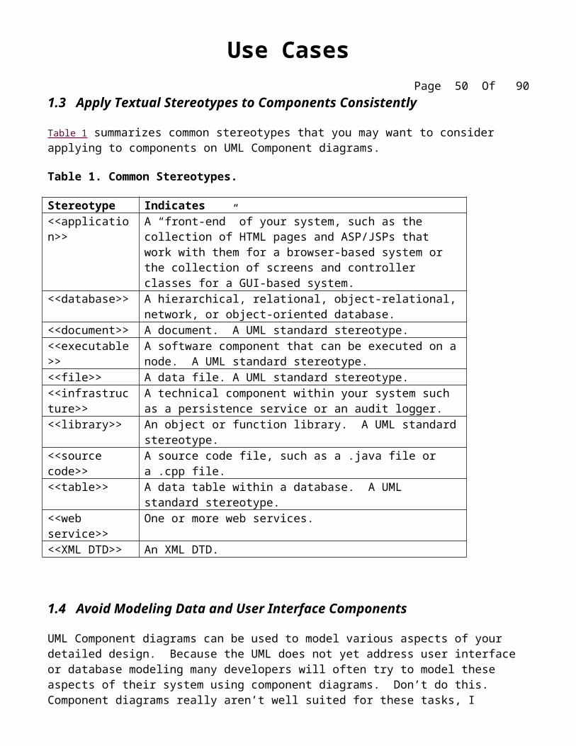
1.3 Apply Textual Stereotypes to Components Consistently
Table 1 summarizes common stereotypes that you may want to consider applying to components on UML Component diagrams.
Table 1. Common Stereotypes.
Stereotype Indicates <<application>> A “front-end” of your system, such as the collection of HTML pages
and ASP/JSPs that work with them for a browser-based system or the collection of screens and controller classes for a GUI-based system.
<<database>> A hierarchical, relational, object-relational, network, or object-oriented database.
<<document>> A document. A UML standard stereotype.<<executable>> A software component that can be executed on a node. A UML
standard stereotype.<<file>> A data file. A UML standard stereotype.<<infrastructure>> A technical component within your system such as a persistence
service or an audit logger.<<library>> An object or function library. A UML standard stereotype.<<source code>> A source code file, such as a .java file or a .cpp file.<<table>> A data table within a database. A UML standard stereotype.<<web service>> One or more web services.<<XML DTD>> An XML DTD.
1.4 Avoid Modeling Data and User Interface Components
UML Component diagrams can be used to model various aspects of your detailed design. Because the UML does not yet address user interface or database modeling many developers will often try to model these aspects of their system using component diagrams. Don’t do this. Component diagrams really aren’t well suited for these tasks, I personally suggest using modified collaboration diagrams for user interface modeling (Ambler 2001) and other methodologists suggest modifications on state charts (Larman 2002) or activity diagrams (Schneider and Winters 2001) and most prefer modified class diagrams for data modeling. However, regardless of what the UML methodologists suggest the fact is that the UML isn’t well suited at the present moment to model these aspects of your system and therefore you are better off applying non-UML artifacts such as user interface flow diagrams and physical data models. My advice is to follow Agile Modeling’s (Ambler 2002) practice of Apply The Right Artifact(s) and pick the right artifact for the job, and in these cases a UML component diagram isn’t it.
2. InterfacesAn interface is a collection of operation signatures and/or attribute definitions that ideally defines a cohesive set of behaviors. Interfaces are implemented, “realized” in UML parlance, by classes and components – to realize an interface a class or component must implement the operations and attributes defined by the interface. Any given class or component may implement zero or more interfaces and one or more classes or components can implement the same interface.
2.1 Prefer Lollipop Notation To Indicate Realization of Interfaces By Components
There are two ways to indicate that a class or component implements an interface: the lollipop notation used in Figure 1 or a realization association (a dashed line with a closed arrowhead) as in Figure 2 with the IStudent interface. The lollipop notation is preferred because it is visually compact – the class box and realization line approach tends to clutter your diagrams.
Figure 2. A UML Component diagram for some student aspects of a university system.
2.2 Prefer the Left-Hand Side of A Component for Interface Lollipops
Although you can put an interface lollipop on any side of a component, the SQL interface is depicted on the right-hand side of TStudent in Figure 2, the most common approach is to place them on the left to increase the consistency within your component diagrams.
2.3 Show Only Relevant Interfaces
Agile Modeling (AM)’s practice Depict Models Simply advises that you keep your diagrams as simple as possible, and one way to do that is to only depict the interfaces that are applicable to the goals of your diagram. For example, in Figure 1 you see that the XML interface is modeled for the Order component but it is not being used, indicating that you might not want to depict it at this time. However, if one of the goals of your model is to show that all of your business/domain components implement this common interface, presumably so that every component has a standard way to get at the data structures which they support, then it makes sense to show it. In short, don’t clutter your diagrams with extraneous information.
3. Dependencies and InheritanceComponents will have dependencies either on other components or better yet on the interfaces of other components. As you can see in Figure 1 and Figure 2 dependencies are modeled using a dashed line with an open arrowhead.
3.1 Model Dependencies From Left To Right
You should strive to arrange your components so that you may draw dependencies from left to right. This increases the consistency of your diagrams and helps you to identify potential circular dependencies in your design. For example a circular dependency exists in Figure 2 – Student.Java depends on updateStudent, which depends on TStudent, which in turn depends on Student.Java. This was easy to detect because the dependence from TStudent to Student.Java went from right-to-left while all others went in the opposite direction.
3.2 Place Child Components Below Parent Components
Inheritance between components is possible, in this case between Shipping and Apache Struts as you see in Figure 1 Error: Reference source not found , and as you can see the inheriting component is shown below the parent component. This approach is consistent to the Place Subclasses Below Superclasses guideline for UML Class diagrams.
By making components dependent on the interfaces of other components, instead of on the other components themselves, you enable yourself to replace the component without having to rewrite the components that depend on it. For example, in Figure 1 the Customer and Order components both depend on the interface to the Persistence component to store them in the database. Perhaps the first implementation of this component was developed in house, but because you quickly found out how complicated persistence can be (Ambler 2001) you instead decided to purchase a persistence framework. To swap this persistence framework into place you merely need to implement the same interface for it, in the case IPersistence. Had your domain components relied on the actual implementation of your “Persistence” component, instead of its interface, you would have needed to rewrite portions of your domain components to use its new implementation.
3.4 Avoid Modeling Compilation Dependencies
Although it is possible to model compilation dependencies in UML Component diagrams there are better ways to record this information, such as in the build scripts for your application. A good rule of thumb is that if you’re showing compilation dependencies on your component diagrams you’ve likely over-modeled your system – step back and ask yourself if this information is actually adding value to your diagram(s).
System Use Casesby Scott W. Ambler, Copyright 2003-2004
The Object Primer 3rd Edition: Agile Model Driven Development with UML 2 is an important reference book for agile modelers, describing how to develop 35 types of agile models including all 13 UML 2 diagrams. Furthermore, this book describes the techniques of the Full Lifecycle Object Oriented Testing (FLOOT) methodology to give you the fundamental testing skills which you require to succeed at agile software development. The book also shows how to move from your agile models to source code (Java examples are provided) as well as how to succeed at implementation techniques such as refactoring and test-driven development (TDD). The Object Primer also includes a chapter overviewing the critical database development techniques (database refactoring, object/relational mapping, legacy analysis, and database access coding) from my award-winning Agile Database Techniques book.
This artifact description is excerpted from Chapter 5 of The Object Primer 3rd Edition: Agile Model Driven Development with UML 2.
A use case is a sequence of actions that provide a measurable value to an actor. Another way to look at it is a use case describes a way in which a real-world actor interacts with the system. In a system use case you include high-level implementation decisions. System use cases can be written in both an informal manner and a formal manner. Techniques for identifying use cases are discussed as well as how to remain agile when writing use cases.
Informal System Use Cases
Let’s start by considering the types of use cases that you’ll write as part of your initial requirements gathering efforts during “cycle 0” of your projects. These use cases will either be essential use cases or “informal” system use cases, an example of which is presented in Figure I-1. As you can see the steps are written in very brief, bullet/point-form style. They contain just enough information to get the idea across and no more. It also takes technology issues into account, for example the text “Student inputs her name and address” implies some sort of information system. The reference to the system also implies the same.
Figure I-1. Enroll in seminar as an informal system use case (automated solution).
Name: Enroll in Seminar
Identifier: UC 17
Basic Course of Action:
Student inputs her name and student number System verifies the student is eligible to enroll in seminars. If not eligible then student informed
and use case ends.
System displays list of available seminars.
Student chooses a seminar or decides not to enroll at all.
System validates the student is eligible to enroll in the chosen seminar. If not eligible student is asked to choose another.
System validates the seminar fits student’s schedule.
System calculates and displays fees
Student verifies the cost and either indicates she wants to enroll or not.
System enrolls the student in the seminar and bills them for it.
The system prints enrollment receipt.
Figure I-2 presents an alternate version, this time as a manual process involving a registrar (a person) instead of an automated system. Choosing a manual process over a software-based one is still a technical architecture decision, in this case a low-tech architectural decision. The differences between the two versions illuminates how system use cases are not analysis and arguably even design artifacts, not requirements artifacts.
Figure I-2. Enroll in Seminar as an informal use case (manual solution).
Name: Enroll in Seminar
Identifier: UC 17
Basic Course of Action:
Student inputs her name and student number Registrar verifies the student is eligible to enroll in seminars. If not eligible then student informed
and use case ends.
Use CasesPage 44 Of 69
Registrar asks student which seminar they’d like to enroll in. If they don’t know registrar provides student with course catalog if required.
Student chooses a seminar or decides not to enroll at all.
Registrar checks student record to see if student has previously passed prerequisite courses. If not eligible student is asked to choose another.
Registrar validates the seminar fits into student’s schedule.
Registrar calculates fees
Student verifies the cost and either indicates she wants to enroll or not.
Registrar enrolls the student in the seminar and bills them for it.
The registrar writes enrollment receipt.
Formal System Use Cases
Figure 1 presents a formalized version of Figure I-1. This version is much more detailed than the corresponding use case, and is typical of the type of use cases that people will write in documentation-intense environments. Frankly, use cases like this are overkill for many projects yet many project teams are required to write them in this manner (or something similar) because senior management is convinced that they require this level of documentation. My advice is to keep your models as simple as possible and only document them this thoroughly if it adds actual value.
A formalized system use case refers to specific user interface componentssuch as screens, HTML pages, or reportssomething you wouldn’t do in an essential/business use case. During analysis, you make decisions regarding what will be built, information reflected in your use cases, and, arguably, even how it will be built (effectively design). Because your use cases refer to user interface components, and because your user interface is worked on during design, inevitably design issues will creep into your use cases. For example, a design decision is whether your user interface is implemented using browser-based technology, such as HTML pages or graphical user interface (GUI) technology such as Windows. Because your user interface will work differently depending on the implementation technology, the logic of your system use cases, which reflect the flow of your user interface, will also be affected.
Figure 1. Enroll in Seminar as a formal system use case.
Name: Enroll in Seminar
Identifier: UC 17
Description:
Enroll an existing student in a seminar for which she is eligible.
The Student will be enrolled in the course she wants if she is eligible and room is available.
Basic Course of Action:
StudentSummerUC
The use case begins when a student wants to enroll in a seminar.
(1) The student inputs her name and student number into the system via UI23 Security Login Screen.(a) The system verifies the student is eligible to enroll in seminars at the university
according to business rule BR129 Determine Eligibility to Enroll. [Alt Course A]
(b) The system displays UI32 Seminar Selection Screen, which indicates the list of available seminars.
(2) The student indicates the seminar in which she wants to enroll. [Alt Course B: The Student Decides Not to Enroll]
(a) The system validates the student is eligible to enroll in the seminar according to the business rule BR130 Determine Student Eligibility to Enroll in a Seminar. [Alt Course C]
(b) The system validates the seminar fits into the existing schedule of the student according to the business rule BR143 Validate Student Seminar Schedule.
(c) The system calculates the fees for the seminar based on the fee published in the course catalog, applicable student fees, and applicable taxes. Apply business rules BR 180 Calculate Student Fees and BR45 Calculate Taxes for Seminar.
(d) The system displays the fees via UI33 Display Seminar Fees Screen.
(e) The system asks the student if she still wants to enroll in the seminar.
(3) The student indicates she wants to enroll in the seminar.
(a) The system enrolls the student in the seminar.
(b) The system informs the student the enrollment was successful via UI88 Seminar
Use CasesPage 46 Of 69
Enrollment Summary Screen.
(c) The system bills the student for the seminar, according to business rule BR100 Bill Student for Seminar.
(d) The system asks the student if she wants a printed statement of the enrollment.
(4) The student indicates she wants a printed statement.
(5) The system prints the enrollment statement UI89 Enrollment Summary Report.
18. The use case ends when the student takes the printed statement.
Alternate Course A: The Student is Not Eligible to Enroll in Seminars.
A.3. The registrar determines the student is not eligible to enroll in seminars.
A.4. The registrar informs the student he is not eligible to enroll.
A.5. The use case ends.
Alternate Course B: The Student Decides Not to Enroll in an Available Seminar
B.5. The student views the list of seminars and does not see one in which he wants to enroll.
B.6. The use case ends.
Alternate Course C: The Student Does Not Have the Prerequisites
C.6. The registrar determines the student is not eligible to enroll in the seminar he chose.
C.7. The registrar informs the student he does not have the prerequisites.
C.8. The registrar informs the student of the prerequisites he needs.
C.9. The use case continues at Step 4 in the basic course of action.
Figure 2. Enroll in University as a formal system use case.
Name: Enroll in University
Identifier: UC 19
Use CasesPage 47 Of 69
Description:
Enroll someone in the university.
Preconditions:
The Registrar is logged into the system. The Applicant has already undergone initial checks to verify that they are eligible to enroll.
Postconditions:
The Applicant will be enrolled in the university as a student if they are eligible.
Basic Course of Action:
1. An applicant wants to enroll in the university.
2. The applicant hands a filled out copy of form UI13 University Application Form to the registrar. [Alternate Course A: Forms Not Filled Out]
3. The registrar visually inspects the forms.
4. The registrar determines that the forms have been filled out properly. [Alternate Course B: Forms Improperly Filled Out].
5. The registrar clicks on the Create Student icon.
6. The system displays UI89 Create Student Screen.
7. The registrar inputs the name, address, and phone number of the applicant. [Extension Point: UC34 Perform Security Check. Applicable to Step 17]
8. The system determines that the applicant does not already exist within the system according to BR37 Potential Match Criteria for New Students. [Alternate Course F: Students Appears to Exist Within The System].
9. The system determines that the applicant is on the eligible applicants list. [Alternate Course G: Person is Not Eligible to Enroll]
10. The system adds the applicant to its records. The applicant is now considered to be a student.
11. The registrar helps the student to enroll in seminars via the use case UC 17 Enroll in Seminar.
12. The system calculates the required initial payment in accordance to BR16 Calculate Enrollment Fees.
Use CasesPage 48 Of 69
13. The system displays UI15 Fee Summary Screen.
14. The registrar asks the student to pay the initial payment in accordance to BR19 Fee Payment Options.
15. The student pays the initial fee. [Alternate Course D: The Student Can’t Pay At This Time]
16. The system prints a receipt.
17. The registrar hands the student the receipt.
18. The use case ends.
Alternate Course A: Forms Not Filled Out
A.2. The Applicant asks for a set of forms.
A.3. The Applicant fills out the forms as appropriate.
A.4. The use case continues at step 2 in the basic course of action.
Alternate Course B: ....
Figure 2 presents a formalized system use case (also called a traditional or concrete use case) for enrolling in the university. Interesting points about it:
The system use case has many implementation details embedded within it. For example, it references "the term system" indicating a decision has been made to automate many of the mundane aspects of enrollment. The writer of system use cases is analyzing and describing requirements imposed by the problem, intermingled with implicit decisions about what the user interface is going to be like.
Use case steps are written in the active voice. Writing in the active voice leads to succinct sentences. For example, the statement “The registrar informs the student of the fees” is in active voice whereas “The student is informed of the fees by the registrar” is in passive voice.
Each use case step reflects one activity and one activity only. Several advantages exist to this approach:
o the use case becomes easier to test because each statement is easier to understand and validate
o alternate courses are easier to write because it is easier to branch from a statement when it does one thing only.
o Begin and End the basic course of action within a use case with a statement. indicating that the logic for the course of action has been completely defined.
Referenceso The system use case makes references to screen and reports, for example, UI23 Security
Login Screen and UI89 Enrollment Summary Report. Once again this reflects implementation details, someone has decided the system will be implemented as screens, as opposed to HTML pages perhaps, and printed reports.
o The use case references business rule definitionssuch as BR129 Determine Eligibility to Enroll because business rules reflect essential characteristics of your domain that your system must implement. For very simple systems without very many complex business rules I’ll often keep it simple and document the rule within the use case. Different situations call for different approaches, hence the importance of AM’s Local Adaptation principle.
An alternate course of action is an infrequently used path of logic in a use case. o Alternate courses are identified whenever there is an alternate way to work, an exception,
or an error condition that must be handled. The use case text references several alternate courses, think of them simply as the use case way of doing if/then logic, one of which is described at the bottom of the use case.
How to Draw UML 2 Use Case Diagramsby Scott W. Ambler, Copyright 2003-2004
The Object Primer 3rd Edition: Agile Model Driven Development with UML 2 is an important reference book for agile modelers, describing how to develop 35 types of agile models including all 13 UML 2 diagrams. Furthermore, this book describes the techniques of the Full Lifecycle Object Oriented Testing (FLOOT) methodology to give you the fundamental testing skills which you require to succeed at agile software development. The book also shows how to move from your agile models to source code (Java examples are provided) as well as how to succeed at implementation techniques such as refactoring and test-driven development (TDD). The Object Primer also includes a chapter overviewing the critical database development techniques (database refactoring, object/relational mapping, legacy analysis, and database access coding) from my award-winning Agile Database Techniques book.
This artifact description is excerpted from Chapter 5 of The Object Primer 3rd Edition: Agile Model Driven Development with UML 2.
The use case diagram in Figure 1 provides an example of an UML use case diagram.
Use case diagrams depict:
Use cases. A use case describes a sequence of actions that provide something of measurable value to an actor and is drawn as a horizontal ellipse.
Actors. o An actor is a person, organization, or external system that plays a role in one or more interactions
with your system. o Actors are drawn as stick figures. o Actors are always involved with at least one use case o Actors are always drawn on the outside edges of a use case diagram.
Associations. o Associations between actors and use cases are indicated in use case diagrams by solid lines. o Association(s) exists whenever an actor is involved with an interaction described by a use case.
o Associations are modeled as lines connecting use cases and actors to one another, with an optional arrowhead on one end of the line. The arrowhead is often used to indicating the direction of the initial invocation of the relationship or to indicate the primary actor within the use case. The arrowheads are typically confused with data flow and as a result I avoid their use.
System boundary boxes (optional). o Drawn as a rectangle around the use cases, called the system boundary box, to indicate the scope
of your system. o Anything within the box represents functionality that is in scope and anything outside the box is
not. o System boundary boxes are rarely used, although on occasion I have used them to identify which
use cases will be delivered in each major release of a system (Ambler 2003b). Figure 2 shows how this could be done.
Packages (optional). o Packages are UML constructs that enable you to organize model elements (such as use cases)
into groups. o Packages are depicted as file folders and can be used on any of the UML diagrams, including both
use case diagrams and class diagrams. I use packages only when my diagrams become unwieldy, which generally implies they cannot be printed on a single page, to organize a large diagram into smaller ones. Figure 3 depicts how Figure 1 could be reorganized with packages.
In the example depicted in Figure 1 students are enrolling in courses with the potential help of registrars. Professors input the marks students earn on assignments and registrars authorize the distribution of transcripts (report cards) to students. Note how for some use cases there is more than one actor involved. Moreover, note how some associations have arrowheadsany given use case association will have a zero or one arrowhead. The association between Student and Enroll in Seminar indicates this use case is initially invoked by a student and not by a registrar (the Registrar actor is also involved with this use case).
Understanding that associations don’t represent flows of information is important They merely indicate an actor is somehow involved with a use case. Information is flowing back and forth between the actor and the use case. For example, students would need to indicate which seminars they want to enroll in and the system would need to indicate to the students whether they have been enrolled. However, use case diagrams don’t model this sort of information. Information flow can be modeled using UML activity diagrams. The line between the Enroll in Seminar use case and the Registrar actor has no arrowhead, indicating it is not clear how the interaction between the system and registrars start. Perhaps a registrar may notice a student needs help and offers assistance, whereas other times, the student may request help from the registrar, important information that would be documented in the description of the use case.
Figure 2. Using System boundary boxes to indicate releases.
Use CasesPage 52 Of 69
Figure 3. Applying packages to simplify use case diagrams.
Creating Use Case Diagrams
I like to start by identifying as many actors as possible. You should ask how the actors interact with the system to identify an initial set of use cases. Then, on the diagram, you connect the actors with the use cases with which they are involved. If an actor supplies information, initiates the use case, or receives any information as a result of the use case, then there should be an association between them. I generally don’t include arrowheads on the association lines because my experience is that people confuse them for indications of information flow, not initial invocation. As I begin to notice similarities between use cases, or between actors, I start modeling the appropriate relationships between them (see the Reuse Opportunities section).
The preceding paragraph describes my general use case modeling style, an “actors first” approach. Others like to start by identifying one actor and the use cases that they’re involved with first and then evolve the model from there. Both approaches work. The important point is that different people take different approaches so you need to be flexible when you’re following AM’s practice of Model With Others.
Reuse Opportunities
Figure 4 shows the three types of relationships between use cases -- extends, includes, and inheritance -- as well as inheritance between actors. I like to think of extend relationships as the equivalent of a "hardware interrupt" because you don't know when or if the extending use case will be invoked (perhaps a better way to look at this is extending use cases are conditional). Include relationships as the equivalent of a procedure call. Inheritance is applied in the same way as you would on UML class diagrams -- to model specialization of use cases or actors in this case. The essay Reuse in Use Case Models describes these relationships in greater detail.
So how can you keep use case modeling agile? First, focus on keeping it as simple as possible. Use simple, flexible tools to model with. I’ll typically create use case diagrams on a whiteboard, as you see in Figure 5 which is an example of an initial diagram that I would draw with my project stakeholders. AM tells us that Content is More Important Than Representation so it isn’t a big issue that the diagram is hand drawn, it’s just barely good enough and that’s all that we need. It’s also perfectly okay that the diagram isn’t complete, there’s clearly more to a university than what is depicted, because we can always modify the diagram as we need to.
In parallel to creating the sketch I would also write a very brief description of each use case, often on a whiteboard as well. The goal is to record just enough information about the use case so that we understand what it is all about. If we need more details we can always add them later either as an essential/business use case or a system use case.
Notice: This artifact description has been excerpted from The Object Primer 3rd Edition: Agile Modeling Driven Development with UML 2.
UML 2 Activity Diagramsby Scott W. Ambler, Copyright 2003-2004
The Object Primer 3rd Edition: Agile Model Driven Development with UML 2 is an important reference book for agile modelers, describing how to develop 35 types of agile models including all 13 UML 2 diagrams. Furthermore, this book describes the techniques of the Full Lifecycle Object Oriented Testing (FLOOT) methodology to give you the fundamental testing skills which you require to succeed at agile software development. The book also shows how to move from your agile models to source code (Java examples are provided) as well as how to succeed at implementation techniques such as refactoring and test-driven development (TDD). The Object Primer also includes a chapter overviewing the critical database development techniques (database refactoring, object/relational mapping, legacy analysis, and database access coding) from my award-winning Agile Database Techniques book.
This artifact description is excerpted from Chapter 9 of The Object Primer 3rd Edition: Agile Model Driven Development with UML 2.
UML 2.x activity diagrams (Object Management Group 2003) are typically used for business process modeling, for modeling the logic captured by a single use case or usage scenario, or for modeling the detailed logic of a business rule. Although UML activity diagrams could potentially model the internal logic of a complex operation it would be far better to simply rewrite the operation so that it is simple enough that you don’t require an activity diagram. In many ways UML activity diagrams are the object-oriented equivalent of flow charts and data flow diagrams (DFDs) from structured development.
Let’s start by describing the basic notation (there’s more) that I’ve used in Figures 1 and 2:
Initial node. The filled in circle is the starting point of the diagram. An initial node isn’t required although it does make it significantly easier to read the diagram.
Activity final node. The filled circle with a border is the ending point. An activity diagram can have zero or more activity final nodes.
Activity. The rounded rectangles represent activities that occur. An activity may be physical, such as Inspect Forms, or electronic, such as Display Create Student Screen.
Flow/edge. The arrows on the diagram. Although there is a subtle difference between flows and edges I have never seen a practical purpose for the difference although I have no doubt one exists. I’ll use the term flow.
Fork. A black bar with one flow going into it and several leaving it. This denotes the beginning of parallel activity.
Join. A black bar with several flows entering it and one leaving it. This denotes the end of parallel processing.
Condition. Text such as [Incorrect Form] on a flow, defining a guard which must evaluate to true in order to traverse the node.
Decision. A diamond with one flow entering and several leaving. The flows leaving include conditions although some modelers will not indicate the conditions if it is obvious.
Merge. A diamond with several flows entering and one leaving. The implication is that all incoming flows must reach this point until processing continues, unless otherwise noted as in Figure 2 (discussed below).
Partition. Figure 2 is organized into three partitions, also called swimlanes, indicating who/what is performing the activities (either the Applicant, Registrar, or System).
Sub-activity indicator. The rake in the bottom corner of an activity, such as in the Apply to University activity, indicates that the activity is described by a more finely detailed activity diagram. In Figure 2 the Enroll In Seminar activity includes this symbol.
Flow final. The circle with the X through it. This indicates that the process stops at this point. Note. Figure 2 includes a standard UML note to indicate that the merges does not require all three
flows to arrive before processing can continue. An alternative way to model this would have been with an OR constraint between the no match and applicant not on match list flows. I prefer notes because stakeholders find them easier to understand.
Use case. In Figure 1 I indicated that the Enroll in Seminar use case is invoked as one of the activities. This is a visual cheat that I use to indicate that an included use case is being invoked. To tell you the truth I’m not sure if this is official allowed by the UML but clearly it should be. Another way to depict this is shown in Figure 2 via the use of a normal activity although I don’t think this is as obvious as using a use case.
The activity diagram of Figure 1 depicts one way to model the logic of the Enroll in University use case , a very common use of activity diagrams because they enable you to depict both the basic course of action as well as the alternate courses. Activity diagrams can also be drawn that cross several use cases, or that address just a small portion of a use case. You can also use activity diagrams without use cases being involved at all, for example a pair of eXtreme Programming (XP) developers (Beck 2000) could draw activity diagrams
with their customer (the XP term for stakeholder) to analyze a user story or a larger business process that a user story supports.
Figure 1. UML activity diagram for the Enroll in University use case.
Figure 1 is notable for several things:
1. It depicts the notation that you’re likely to use 90% of the time (I’ll discuss the more esoteric notation later).
2. The use of diamonds for decisions and merges is visually wordy but unfortunately all too common. In Figure 2 I address this issue by placing conditions on flows leaving activities instead of introducing additional diamonds to represent decision points.
3. It uses a fork to indicate parallel processing, in this case we’ve decided that we can perform some of the checks on the applicant in parallel, something that wasn’t easy to indicate using flow charts.
4. It shows how activity diagrams can get large very quickly. Even though it models the logic of a single use case I was forced to have it wind around the whiteboard because I ran out of space. Ideally the diagram should be wider, with the logic going from left-to-right across the board. Better yet, it would be nice to have more whiteboard space.
5. It includes a common mistake. At the very end I applied a decision just before the Process Payment and Print Receipt processes to indicate that they can be done in parallel. I should have used a fork, not a decision, for that. I should also use a balancing join, instead of a merge, although either one would be allowed. The join or merge is required because both processes need to finish before the overall process ends, without doing this a race condition effectively exists where the first process to finish would end things.
Figure 2 depicts the Enroll in University use case but takes a different approach than. As noted above it avoids the use of decision points. It also uses the concept of partitions, also called swim lanes, to indicate who/what is performing the activity. In this diagram I simply labeled the partitions with the text Applicant, Registrar, and System although it is also common to put actor symbols (stick figures) to make it very clear that an actor is performing some activities. Partitions are useful because they provide more
information, but they also elongate the diagram – I ran out of room and was forced to finish the diagram on another whiteboard (not shown), using a connector (the circle with the letter A in it), to help show how the physical separate portions fit together. A common use of connectors is to avoid a line going from one side of a diagram to another. Instead you show a flow entering a connector and a second flow leaving a similarly labeled connector, e.g. both connectors have the letter B in them, going into the target activity. Figure 2 also depicts how to apply a flow final, the circle with the X through it, as well as a note to indicate a constraint on a merge, as noted above.
Figure 2. UML activity diagram with partitions based on actors.
The style of partitions in Figure 2 is often referred to as “swim lanes” because the partitions look like the lanes in a swimming pool. Figure 3 takes a different approach, I guess you could call the partitions “swim areas”. As you can see swim areas take up less room than swim lanes. It’s also interesting to note that the partitioning strategies between the two diagrams are different – Figure 2 is partition by actor whereas Figure 3 is partitioned by courses of action within a use case. As always, my advice is to use the strategy best suited for your situation.
Figure 3. UML activity diagram with partitions based on alternate courses.
Figure 3 uses a notation that we haven’t seen before, the five-sided Possible Security Risk signal. This symbol indicates that an event has occurred, that we’ve determined that there is a possible security risk, and therefore the Perform Security Check use case may need to be triggered.
Figure 4 depicts a UML activity diagram for the Distribute Schedules use case, this time I’ve used a drawing tool so you can see a clean example of the notation. The activity starts when the Schedule Printed signal is received, this signal would be sent from one or more other activity diagrams, and it’s April 1st (or later). The hour-glass symbol represents time, and because all of the flows going into a join must occur before processing can continue the way that you would read this is that the schedules must be printed and it has to be at least April 1st. In fact, I’ve chosen to indicate this with a join specification, basically a constraint associated to a join in the format {joinSpec = …}. In this case the join specification is completely redundant so there isn’t any value in indicating it other than the fact that I wanted to show you an example. The only time that I indicate join specifications is when there is a constraint that isn’t obvious from the incoming flows. For example, if the schedules needed to be distributed before April 21st
then I would likely indicate this with a join specification.
The square on the side of the Determine Mailing List activity in Figure 4 is called a pin, and the one on the side of the Print Mailing Label activity is a parameter. The circle on the flow indicates a transformation, in this case the people on the mailing list are sorted by zip code (the post office charges less for bulk mailings that are sorted in this manner) and then each individual is listed so that a mailing label can then be printed for each individual.
The Labeled Schedule box is an example of an object being passed between activities. I rarely show objects in this manner as I feel this notation is a little bit goofy. You can usually read between the lines and determine what is flowing between activities, for example it is clear that labels are being passed from the Print Mailing Label activity to the Attach Labels to Schedules activity.
Notice: This artifact description has been excerpted from The Object Primer 3rd Edition: Agile Modeling Driven Development with UML 2. The book goes into greater detail.
Suggested Reading
Activity Diagramming Guidelines
UML Activity Diagramming Guidelinesby Scott W. Ambler, Copyright 2002-2004
In many ways UML Activity diagrams are the object-oriented equivalent of flow charts and data-flow diagrams (DFDs) from structured development (Gane & Sarson 1978). They are used to explore the logic of:
A complex operation A complex business rule A single use case
Decision Points Should Reflect the Previous Activity Avoid Superfluous Decision Points
Guards
Each Transition Leaving a Decision Point Must Have a Guard Guards Should Not Overlap
Guards on Decision Points Must Form a Complete Set
Exit Transition Guards and Activity Invariants Must Form a Complete Set
Apply a [Otherwise] Guard for “Fall Through” Logic
Guards Are Optional
Parallel Activities A Fork Should Have a Corresponding Join Forks Have One Entry Transition Joins Have One Exit Transition Avoid Superfluous Forks
Swimlane Guidelines Order Swimlanes in a Logical Manner Apply Swim Lanes To Linear Processes Have Less Than Five Swimlanes Consider Swimareas For Complex Diagrams Swimareas Suggest The Need to Reorganize Into Smaller Activity Diagrams Consider Horizontal Swimlanes for Business Processes
Place Shared Action Objects on Swimlane Separators When An Object Appears Several Time Apply State Names
State Names Should Reflect the Lifecycle Stage of an Action Object
Show Only Critical Inputs and Outputs
Depict Action Objects As Smaller Than Activities
1. General Guidelines
1.1 Place The Start Point In The Top-Left Corner
A start point is modeled with a filled in circle, using the same notation that UML State Chart diagrams use. Every UML Activity Diagram should have a starting point, and placing it in the top-left corner reflects the way that people in Western cultures begin reading. Error: Reference source not found, which models the business process of enrolling in a university, takes this approach.
Figure 3. Modeling a business process with a UML Activity Diagram.
1.2 Always Include an Ending Point
An ending point is modeled with a filled in circle with a border around it, using the same notation that UML State Chart diagrams use. Fowler and Scott's (1999) style is to make ending points optional, some times an activity is simply a dead end, but if this is the case then there is no harm in indicating that the
only transition is to an ending point. That way when someone else reads your diagram they know that you have considered how to exit these activities.
Error: Reference source not foundis interesting because it does not include an end point because it describes a continuous process – sometimes the guidelines don’t apply.
1.3 Flowcharting Operations Implies the Need to Simplify
A good rule of thumb is that if an operation is so complex you need to develop a UML Activity diagram to understand it that you should consider refactoring it.
2. ActivitiesAn activity, also known as an activity state, on a UML Activity diagram typically represents the invocation of an operation, a step in a business process, or an entire business process.
2.1 Question “Black Hole” Activities
A black hole activity is one that has transitions into it but none out, typically indicating that you have either missed one or more transitions. As noted previously if an activity is in fact the final activity in the process you are modeling you should consider adding a transition out of it to an end point.
2.2 Question “Miracle” Activities
A miracle activity is one that has transitions out of it but none into it, something that should be true only of start points. Once again, this is an indication that you have missed one or more transitions.
3. Decision PointsA decision point is modeled as a diamond on a UML Activity diagram.
Use CasesPage 63 Of 69
3.1 Decision Points Should Reflect the Previous Activity
In Error: Reference source not foundyou see that there is no label on the decision point, unlike traditional flowcharts which would include text describing the actual decision being made, you need to imply that the decision concerns whether the person was enrolled in the university based on the activity that the decision point follows. The guards, depicted using the format [description], on the transitions leaving the decision point also help to describe the decision point.
3.2 Avoid Superfluous Decision Points
The Fill Out Enrollment Forms activity in Error: Reference source not found includes an implied decision point, a check to see that the forms are filled out properly, which simplified the diagram by avoiding an additional diamond.
4. GuardsA guard is a condition that must be true in order to traverse a transition.
4.1 Each Transition Leaving a Decision Point Must Have a Guard
This ensures that you have thought through all possibilities for that decision point.
4.2 Guards Should Not Overlap
The guards on the transitions leaving a decision point, or an activity, must be consistent with one another. For example guards such as x <0, x = 0, and x > 0 are consistent whereas guard such as x <= 0 and x >= 0 are not consistent because they overlap – it isn’t clear what should happen when x is 0. You see that this is true in Error: Reference source not found, the guards on the exit transitions from the Fill Out Enrollment Forms activity do not overlap, nor do the guards on the decision point.
Use CasesPage 64 Of 69
4.3 Guards on Decision Points Must Form a Complete Set
Once you have reached a decision point it must always be possible to leave it, therefore the guards on its exit transitions must be complete. For example, guards such as x < 0 and x >0 are not complete because it isn’t clear what happens when x is 0.
4.4 Exit Transition Guards and Activity Invariants Must Form a Complete Set
An activity invariant is a condition that is always true when your system is processing an activity. For example, in Error: Reference source not foundan invariant of the Enroll In University activity is that the person is not yet officially a student. Clearly the conditions that are true while processing an activity must not overlap with its exit conditions and the invariants and exit conditions must “add up” to a complete set.
4.5 Apply a [Otherwise] Guard for “Fall Through” Logic
In Error: Reference source not foundyou see that one of the transitions on the decision point is labeled Otherwise, a catch-all condition for the situation when the problems with the forms are not trivial and help is not available. This enabled me to avoid a very wordy guard, simplifying the diagram.
4.6 Guards Are Optional
It is very common for a transition to not include a guard, even when an activity includes several exit transitions. When a UML Activity Diagram is used to model a software process (Figure 2 ) or business process (Figure3 ) the transitions often represent sharing or movement of information and objects between activities, a situation where guards often make less sense. Follow Agile Modeling (AM)’s (Ambler 2002) principle of Depict Models Simply and only indicate a guard on a transition if it adds value.
5. Parallel ActivitiesIt is possible to show that activities can occur in parallel, as you see in Error: Reference source not founddepicted using two parallel bars. The first bar is called a fork, it has one transition entering it and two or more transitions leaving it. The second bar is a join, with two or more transitions entering it and only one leaving it.
In Error: Reference source not foundyou see that the business process forks into two parallel streams, one where the person attends a presentation and another where they sign up and pay for courses. The process forks, the person performs these activities, and once both streams are complete the process continues from there (in this case it simply ends). In general, for every start (fork) there is an end (join).
5.2 Forks Have One Entry Transition
When you find that you want to have several transitions into the same fork you should first merge them by having them enter a single diamond and then have a single transition from the diamond into the fork. However, this situation is also a good indication that you’ve either missed an activity, likely where the merge occurs, or that you really don’t have parallel activities at this point.
5.3 Joins Have One Exit Transition
The desire to have several exit transitions is a good indication that you still have parallel activities occurring; therefore move your join further along in the overall process.
5.4 Avoid Superfluous Forks
Error: Reference source not founddepicts a simplified description of the software process of enterprise architectural modeling, a part of the Infrastructure Management discipline of the Enterprise Unified Process (EUP). There is significant opportunity for parallelism in this process, in fact all of these activities could happen in parallel, but forks were not introduced because they would only have cluttered the diagram.
6. Swimlane GuidelinesA swimlane is a way to group activities performed by the same actor on an activity diagram or to group activities in a single thread (Douglass 1999). Error: Reference source not found includes three swimlanes, one for each actor.
Figure 4. A UML activity diagram for the enterprise architectural modeling (simplified).
Although there are no semantics behind the ordering of swimlanes there often is a natural ordering for them. For example, in Error: Reference source not foundyou see that the swimlanes are listed left-to-right in the relative order that the activities would occur in a serial process (even though this one is iterative) – stakeholders will start by identifying and prioritizing requirements, the analyst will model them, then the architects will act on them.
6.2 Apply Swim Lanes To Linear Processes
A good rule of thumb is that swimlanes are best applied to linear processes, unlike the one depicted in Error: Reference source not found, where the logic proceeds from one activity to another. For example, the steps that customers take to check an order out of a grocery store are a perfect example of a relatively linear process. This diagram would likely include three swimlanes, one for the customer, one for the checkout clerk, and one for the person who bags the groceries.
Use CasesPage 67 Of 69
6.3 Have Less Than Five Swimlanes
A disadvantage of swimlanes is that they reduce your freedom to arrange activities in a space-effective manner, often increasing the size of your diagrams. When a diagram has a small number of swimlanes there is less chance that this problem will occur.
6.4 Consider Swimareas For Complex Diagrams
When you need several swimlanes, for example if Error: Reference source not foundwhere to include all of the activities of the Infrastructure Management discipline it would include swimlanes for roles such as Reuse Manager, Programme Manager, Software Process Manager, and Human Resource Manager, you would discover that the swimlanes would force you to arrange the activities in a non-optimal way (the transitions between some activities would cross the page). An other approach would be to use swimareas, sections of related activities, instead of a formal swimlane. Fowler and Scott (1999) call these swimareas non-linear zones.
6.5 Swimareas Suggest The Need to Reorganize Into Smaller Activity Diagrams
When a swimarea includes several activities you may instead decide to introduce a UML package, or simply a higher-level activity, that is then described by a detailed UML Activity diagram. For example, Error: Reference source not foundmay simply be the detailed description of a Model The Enterprise activity on a high-level diagram for that EUP discipline.
6.6 Consider Horizontal Swimlanes for Business Processes
In Error: Reference source not foundyou see that the swimlanes are drawn horizontally, going against common convention of drawing them vertically. Because project stakeholders typically like to read from left-to-right this helps to increase the understandability of your UML Activity diagrams used to depict business processes. Also notice how the outside borders of the swimlanes were dropped to simplify the diagram.
Figure 5. Submitting expenses.
Use CasesPage 68 Of 69
7 Action-Object GuidelinesActivities act on objects, In the strict object-oriented sense of the term an action object is a system object, a software construct. In the looser, and much more useful for business application modeling, sense of the term an action object is any sort of item. For example in Error: Reference source not foundthe ExpenseForm action object is likely a paper form.
7.1 Place Shared Action Objects on Swimlane Separators
In Error: Reference source not foundyou see that the ExpenseForm action object is placed on the line separator between the Consultant and Accountant swimlanes. This was done because the ExpenseForm is critical to both swimlanes and because it is manipulated in both, very likely being a something the two people will work together on (at least when there is a problem).
7.2 When An Object Appears Several Time Apply State Names
The ExpenseForm object appears twice on the diagram, an initial version of it and one with errors. To distinguish between them their state names, in this case Initial and Error, are indicated using the same notation for guards on transitions.
Note that this notation may be applied to any object on any UML diagram, including UML Sequence diagrams and UML Collaboration diagrams.
Use CasesPage 69 Of 69
7.3 State Names Should Reflect the Lifecycle Stage of an Action Object
You depict the same action object on a UML Activity diagram in several places because it is pertinent to what is being modeled and because the itself object has changed (it has progressed through one or more stages of its lifecycle).
7.4 Show Only Critical Inputs and Outputs
Although Error: Reference source not foundshows ExpenseForm as an output of the Fill Out Expense Form activity, you know it’s an output because the transition is depicted using a dashed arrow, there isn’t a lot of value in doing so because it’s clear that an expense form would be the output of that activity. Remember AM’s practice Depict Models Simply and only model something if it adds value.
7.5 Depict Action Objects As Smaller Than Activities
The focus of a UML Activity diagram is activities, not the actions implementing or being produced by those activities, therefore you can show this focus by having larger activity bubbles.
To depict the fact that an activity is implemented by an action object you use a solid arrow. In Error: Reference source not foundthe ExpenseValidator object implements the Validate Expenses activity.