Chapter IX Hydraulic and Pneumatic Power Systems The word hydraulics is based on the Greek word for water, and originally meant the study of physical behavior of water at rest and in motion. Today, the meaning has been expanded to include the physical behavior of all liquids including hydraulic fluids. A. Aircraft Hydraulic Systems Hydraulic systems are not new to aviation. Some early aircraft used hydraulic brake systems. As aircraft became more sophisticated, newer systems with greater complexity were developed. Although some aircraft manufacturers make greater use of hydraulic systems than others, the hydraulic system of the average modern aircraft performs many functions. Among the units com- monly operated by hydraulic systems are landing gear, wing flaps, speed and wheel brakes, and flight control surfaces. Hydraulic systems have many advantages as a power source for operating various aircraft units. They combine the advantages of light weight, ease of installation, simplification of inspection, and mini- mum maintenance requirements. Hydraulic opera- tions are almost 100% efficient, with only a negligible loss due to fluid friction. Aircraft hydraulic systems belong to that branch of physics concerned with fluid power/mechanics. They do their work by moving fluid, and the fluid they use is incompressible. Pneumatic systems work in much the same way, obeying many of the same laws, but the fluid they use (air) is compressible. To better understand how a hydraulic system accomplishes its task, a brief review of the physics involved is necessary. 1. Pascal's Law This is the basic law we use when we think of transmitting power by a hydraulic system. The French mathematician Blaise Pascal observed that any increase in the pressure on a confined liquid was transmitted equally and undiminished to all parts of the container, and acts at right angles to the enclos- ing walls of the container. This means simply that if we have an enclosed vessel full of liquid, and we apply a force to a piston in the vessel to raise the pressure, this increase in pressure will be the same anywhere in the system. Each of the gauges attached to the container shown in figure 9-1 will have the same reading. 2. The Hydrostatic Paradox The pressure produced by a column of liquid is directly proportional to its density and the height of the column, and in no way depends upon the shape of the container or the amount of liquid the container holds. For example, 1 cu. in. of water weighs 0.036 lb. A tube that is 231" tall with a cross section of 1 sq. in. will hold 1 gal. of water (1 gal. = 231 cu. in.). If the tube is Figure 9-1. Pressure exerted on a fluid in an enclosed container is transmitted equally and undiminished to all parts of the container and acts at right angles to the enclosing walls. Figure 9-2. The pressure exerted by a column of liquid is determined by the height of the column and is independent of its volume. 121 Aircraft Technical Book Company
Transcript
Chapter IX
Hydraulic and Pneumatic Power Systems
The word hydraulics is based on the Greek word forwater, and originally meant the study of physicalbehavior of water at rest and in motion. Today, themeaning has been expanded to include the physicalbehavior of all liquids including hydraulic fluids.
A. Aircraft Hydraulic SystemsHydraulic systems are not new to aviation. Someearly aircraft used hydraulic brake systems. Asaircraft became more sophisticated, newer systemswith greater complexity were developed.
Although some aircraft manufacturers makegreater use of hydraulic systems than others, thehydraulic system of the average modern aircraftperforms many functions. Among the units com-monly operated by hydraulic systems are landinggear, wing flaps, speed and wheel brakes, and flightcontrol surfaces.
Hydraulic systems have many advantages as apower source for operating various aircraft units.They combine the advantages of light weight, ease ofinstallation, simplification of inspection, and mini-mum maintenance requirements. Hydraulic opera-tions are almost 100% efficient, with only a negligibleloss due to fluid friction.
Aircraft hydraulic systems belong to that branchof physics concerned with fluid power/mechanics.They do their work by moving fluid, and the fluidthey use is incompressible. Pneumatic systems workin much the same way, obeying many of the samelaws, but the fluid they use (air) is compressible.
To better understand how a hydraulic systemaccomplishes its task, a brief review of the physicsinvolved is necessary.
1. Pascal's LawThis is the basic law we use when we think oftransmitting power by a hydraulic system. TheFrench mathematician Blaise Pascal observed thatany increase in the pressure on a confined liquid wastransmitted equally and undiminished to all parts ofthe container, and acts at right angles to the enclos-ing walls of the container. This means simply that ifwe have an enclosed vessel full of liquid, and weapply a force to a piston in the vessel to raise thepressure, this increase in pressure will be the sameanywhere in the system. Each of the gauges attached
to the container shown in figure 9-1 will have thesame reading.
2. The Hydrostatic ParadoxThe pressure produced by a column of liquid is directlyproportional to its density and the height of thecolumn, and in no way depends upon the shape of thecontainer or the amount of liquid the container holds.For example, 1 cu. in. of water weighs 0.036 lb. A tubethat is 231" tall with a cross section of 1 sq. in. willhold 1 gal. of water (1 gal. = 231 cu. in.). If the tube is
Figure 9-1. Pressure exerted on a fluid in an enclosedcontainer is transmitted equally andundiminished to all parts of the containerand acts at right angles to the enclosingwalls.
Figure 9-2. The pressure exerted by a column of liquidis determined by the height of the columnand is independent of its volume.
121
Aircraft Technical Book Company http://www.ACTechbooks.com (800) 780-4115 (970) 887-2207
FORCE AREA x PRESSURE
AREA FORCE / PRESSURE
PRESSURE FORCE / AREA(A)
(B)
(C)
standing straight up, the 1 gal. of water will exert apressure of 8.32 PSI at the bottom of the tube.
If the tube were 231" high and had an area of 100sq. in., it would hold 100 gal. of water, but thepressure at the bottom would still be 8.32 PSI. Theforce exerted by the column of water is, of course,equal to the pressure acting on each square inchtimes the number of square inches, or 832 lbs.
It makes no difference as to the shape or size ofthe vessel that contains the liquid; it is the height ofthe column that is the critical factor. In figure 9-3,the pressure (P) read by the gauges will be the samein all four instances, since the height (H) is the same.Naturally, all of the vessels must be filled with the
same liquid.
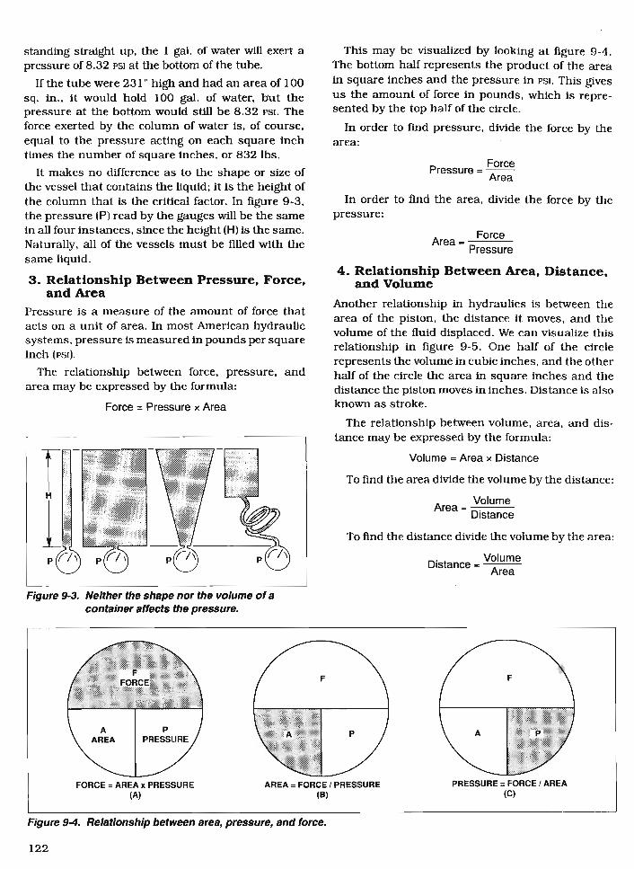
3. Relationship Between Pressure, Force,and Area
Pressure is a measure of the amount of force thatacts on a unit of area. In most American hydraulicsystems, pressure is measured in pounds per squareinch (PSI).
The relationship between force, pressure, andarea may be expressed by the formula:
Force = Pressure x Area
This may be visualized by looking at figure 9-4.The bottom half represents the product of the areain square inches and the pressure in PSI. This givesus the amount of force in pounds, which is repre-sented by the top half of the circle.
In order to find pressure, divide the force by thearea:
Pressure =Force Area
In order to find the area, divide the force by thepressure:
Area = Force Pressure
4. Relationship Between Area, Distance,and Volume
Another relationship in hydraulics is between thearea of the piston, the distance it moves, and thevolume of the fluid displaced. We can visualize thisrelationship in figure 9-5. One half of the circlerepresents the volume in cubic inches, and the otherhalf of the circle the area in square inches and thedistance the piston moves in inches. Distance is alsoknown as stroke.
The relationship between volume, area, and dis-tance may be expressed by the formula:
Volume = Area x Distance
To find the area divide the volume by the distance:
Area = VolumeDistance
To find the distance divide the volume by the area:
Distance = Volume
Area
Figure 9-3. Neither the shape nor the volume of acontainer affects the pressure.
Figure 9-4. Relationship between area, pressure, and force.
122
Aircraft Technical Book Company http://www.ACTechbooks.com (800) 780-4115 (970) 887-2207
AAREA DISTANCE
VVOLUME
VOLUME = AREA x DISTANCE AREA = VOLUME / DISTANCE DISTANCE = VOLUME / AREA(B) (C)
F 1#n W = 20#
AREA20 SO. INCH
llllllll
AREA. 1 SO. INCH
D 1 INCH
-1D = 1/20 INCH
Figure 9-5. Relationship between volume, area, and distance.
5. Mechanical Advantage in a HydraulicSystem
A hydraulic system has two major advantages overother types of mechanical systems. One is the easewith which force can be transmitted over large dis-tances and into and out of sealed compartments. Theother is the mechanical advantage made possible byvarying the size of pistons.
In figure 9-6, we see the way mechanical ad-vantage is achieved in a hydraulic system. If we havea piston whose area is 1 sq. in. pressing down witha force of 1 lb., it will produce a pressure of 1 PSI,and for every inch it moves, will displace 1 cu. in. offluid.
If the cylinder containing this piston is connectedto one having a piston with an area of 20 sq. in.,every square inch will be acted on by the same 1 PSIpressure, and a force of 20 lbs. will be produced. The1 cu. in. of fluid displaced when the small piston
Figure 9-6. The product of the force times the area ofthe large piston is equal to the product ofthe weight times the area of the smallpiston.
moves down 1 in. spreads out under all 20 sq. in. ofthe large piston, and will move up only 1/2o".
This may be expressed as:
A (small) x D (small) = A (large) x D (large)
1 x 1 = 20 x 1/2o
1 = 1
All hydraulic systems are essentially the same,whatever their function. Regardless of application,each hydraulic system has a minimum number ofcomponents, and some type of hydraulic fluid.
B. Hydraulic FluidWhile we may not normally think of fluid as being acomponent, the fluid used in aircraft hydraulic sys-tems is most important. This fluid must flow with aminimum of opposition, and be incompressible. Itmust have good lubricating properties to preventwear in the pump and valves. It must inhibit cor-rosion and not chemically attack seals used in thesystem. And it must not foam in operation, becauseair carried into the components will give them aspongy action.
Manufacturers of hydraulic devices specify thetype of fluid best suited for use with their equipment.Working conditions, service, temperatures, pres-sures, possibilities of corrosion, and other condi-tions must be considered. Some of thecharacteristics that must be considered when select-ing a satisfactory fluid for a particular system arediscussed in the following paragraphs.
1. ViscosityOne of the most important properties of anyhydraulic fluid is its viscosity. Viscosity is ameasure of internal resistance to flow. A liquidsuch as gasoline flows easily (has a low viscosity)while a liquid such as tar flows slowly (has a high
123
Aircraft Technical Book Company http://www.ACTechbooks.com (800) 780-4115 (970) 887-2207
HEATINGUNIT LIQUID
BATHTHERMOMETER
CORKCONTAINER
60c.c.
OIL
n \D. . •
4/ Ar
RESERVOIR
viscosity). Viscosity increases as temperature
decreases.
The viscosity of a liquid is measured with a vis-cosimeter. There are several types, but the instrumentmost often used is the Saybolt universal viscosimeter(figure 9-7). This instrument measures the number ofseconds it takes for a fixed quantity of liquid (60 cc) toflow through a small orifice of standard length anddiameter at a specific temperature. This time of flow ismeasured in seconds, and the viscosity reading ex-pressed as SSU (seconds, Saybolt universal).
2. Chemical StabilityChemical stability is another property which is impor-tant in selecting a hydraulic fluid. It is the ability of theliquid to resist oxidation and deterioration for longperiods. Mostl liquids tend to undergo unfavorablechemical changes during severe operating conditions.This is the case when a system operates for a consid-erable period of time at high temperatures.
Excessive temperatures have an adverse effect onthe life of a liquid. The temperature of the liquid inthe reservoir of an operating hydraulic system doesnot always represent a true state of operating con-ditions. Localized hot spots occur on bearings, gearteeth, or at the point where liquid under pressure isforced through a small orifice. Continuous passageof a liquid through these points may produce localtemperatures high enough to carbonize or sludge theliquid, yet the liquid in the reservoir may not indicatean excessively high temperature. Liquids with a highviscosity have a greater resistance to heat than light
Figure 9-7. Saybolt viscosimeter.
or low viscosity liquids which have been derived fromthe same source. Fortunately, there is a wide choiceof liquids available for use within the viscosity rangerequired of hydraulic systems.
Liquids may break down if exposed to air, water,salt, or other impurities, especially if in constantmotion or subject to heat. Some metals, such as zinc,lead, brass, and copper have an undesirable chemi-cal reaction on certain liquids.
These chemical processes result in the formationof sludge, gums, carbon or other deposits which clogopenings, cause valves and pistons to stick or leak,and give poor lubrication to moving parts. As soonas small amounts of sludge or other deposits areformed, their rate of formation generally increases.As they are formed, certain changes in the physicaland chemical properties of the liquid take place. Theliquid usually becomes darker in color, higher inviscosity, and acids are formed.
Flash PointFlash point is the temperature at which a substancegives off vapor in sufficient quantity to ignitemomentarily (flash) when a flame is applied. A highflash point is desirable for hydraulic fluids becauseit indicates a good resistance to combustion and alow degree of evaporation at normal temperatures.
Fire PointFire point is the temperature at which a substancegives off vapor in sufficient quantity to ignite andcontinue to burn when exposed to a spark or flame.Like flash point, a high fire point is required ofdesirable hydraulic fluids.
5. Types of Hydraulic FluidTo assure proper system operation and to avoiddamage to nonmetallic components of the hydraulicsystem, the correct fluid must be used.
When adding fluid to a system, use the type specifiedin the aircraft manufacturer's maintenance manual oron the instruction plate affixed to the reservoir or unitbeing serviced. There are three types of hydraulic fluidscurrently being used in civil aircraft.
a. Vegetable-base FluidMIL-H-7644 fluid has been used in the past whenhydraulic system requirements were not as severeas they are today. This fluid is essentially castor oiland alcohol. Although it is similar to automotivebrake fluid it is not interchangeable. This fluid isused primarily in older type aircraft. It is dyed bluefor identification. Natural rubber seals are used withvegetable base fluid. If this system is contaminatedwith petroleum base or phosphate ester base fluids,
124
Aircraft Technical Book Company http://www.ACTechbooks.com (800) 780-4115 (970) 887-2207
the seals will swell, break down and block the sys-tem. The system may be flushed with alcohol. Thistype of fluid is flammable.
Mineral-base Fluid
MIL-H-5606 is the most widely used hydraulic fluidin general aviation aircraft today. It is basically akerosene-type petroleum product, having goodlubricating properties and additives to inhibit foam-ing and prevent corrosion. It is quite stable chemi-cally and has very little viscosity change withtemperature. MIL-H-5606 fluid is dyed red for iden-tification, and systems using this fluid may beflushed with naphtha, varsol, or Stoddard solvent.Neoprene seals and hoses may be used with MIL-H-5606 fluid. This type of fluid is flammable.
Synthetic Fluid
Non-petroleum base hydraulic fluids were intro-duced in 1948 to provide a fire-resistant hydraulicfluid for use in high performance piston engine andturbine powered aircraft.
The most commonly used fluid of this type isMIL-H-8446 or, Skydrol® (a registered trade nameof the Monsanto Chemical Co.). This fluid is coloredlight purple, is slightly heavier than water, and hasa wide range of operating temperatures from around-65°F to over 225°F for sustained operation. Cur-rently there are two grades of Skydrol in use, Skydrol500B4, and Skydrol LD. Skydrol LD has a lowerdensity and offers some advantage in jumbo jettransport aircraft where weight is a prime factor.
Skydrol is not without its problems however, as itis quite susceptible to contamination by water fromthe atmosphere and must be kept tightly sealed.When servicing a system using Skydrol, be extreme-ly careful to use only seals and hoses having theproper part number. Skydrol systems may beflushed out with trichlorethylene.
Intermixing of FluidsDue to the difference in composition, vegetable base,petroleum base and phosphate ester base fluids willnot mix. Neither are the type of seals for any one fluidusable with or tolerant of any of the other fluids.Should an aircraft hydraulic system be serviced withthe wrong type of fluid, immediately drain and flushthe system and maintain the seals according to themanufacturer's specifications.
Compatibility with Aircraft MaterialsAircraft hydraulic systems designed for Skydrolfluids should be virtually trouble-free if properlyserviced. Skydrol does not appreciably affect com-mon aircraft metals as long as the fluid is kept freeof contamination.
Due to the phosphate ester base of synthetichydraulic fluids, thermoplastic resins, includingvinyl compositions, nitrocellulose lacquers, oil basepaints, linoleum and asphalt may be softenedchemically by these fluids. Skydrol will attackpolyvinyl chloride, and must not be allowed to dripon to electrical wiring, as it will break down theinsulation. However, this chemical reaction usuallyrequires longer than just momentary exposure; andspills that are wiped up with soap and water do notharm most of these materials.
Skydrol is compatible with natural fibers and witha number of synthetics, including nylon andpolyester, which are used extensively in manyaircraft.
Petroleum oil hydraulic seals of neoprene orBuna-N are not compatible with Skydrol and mustbe replaced with seals of butyl rubber or ethylene-propylene elastomers for units that are intended foruse in systems utilizing phosphate ester basehydraulic fluid. These seals are readily availablefrom suppliers.
8. Health and HandlingSkydrol fluid does not present any particular healthhazard in its recommended use. Skydrol has a verylow order of toxicity when taken orally or applied tothe skin in liquid form. It causes pain on contactwith eye tissue, but animal studies and humanexperience indicate that it causes no permanentdamage. First aid treatment for eye contact includesflushing the eyes immediately with large volumes ofwater and the application of an anesthetic eye solu-tion. If pain persists, the individual should bereferred to a physician.
In mist or fog form, Skydrol is quite irritating tonasal or respiratory passages and generallyproduces coughing and sneezing. Such irritationdoes not persist following cessation of exposure.
Silicone ointments, rubber gloves, and carefulwashing procedures should be utilized to avoid ex-cessive repeated contact with Skydrol in order toavoid solvent effect on skin.
C. Basic Hydraulic SystemsA hydraulic system is much like an electrical system.It must have a source of power, a means of transmit-ting this power, and finally some type of device touse the power.
1. Open Hydraulic SystemsThe most basic form of an open hydraulic system isthat used by hydroelectric power plants. Large damsblock streams of water to form lakes that store
125
Aircraft Technical Book Company http://www.ACTechbooks.com (800) 780-4115 (970) 887-2207