Systematic Design and Implementation of a Micro Unmanned Quadrotor System Swee King Phang * ,§ , Kun Li † , Kok Hwa Yu ‡ , Ben M. Chen † , Tong Heng Lee † * NUS Graduate School for Integrative Sciences and Engineering, National University of Singapore, 21 Lower Kent Ridge Road, Singapore 119077 † Electrical and Computer Engineering, National University of Singapore, 21 Lower Kent Ridge Road, Singapore 119077 ‡ Mechanical Engineering, National University of Singapore, 21 Lower Kent Ridge Road, Singapore 119077 This paper presents a guideline to systematically design and construct a micro quadrotor unmanned aerial vehicle (UAV), capable of autonomous flight. The designed micro UAV has a gross weight of less than 40 g including power supply sufficient for an 8-min flight. The design is divided into three parts. First, investigation is made on the structural design of a conventional quadrotor. The quadrotor frame is then carefully designed to avoid any potential structural natural frequencies within the range of rotors operating speeds, based on simulation results obtained from MSC Nastran. Second, avionic system of the aircraft will be discussed in detail, mainly focusing on the design of printed circuit boards which include sensors, microprocessors and four electronic speed controllers, specially catered for micro quadrotor design. Last, a mathematical model for the micro quadrotor is derived based on Newton–Euler formalism, followed by methods of identifying the parameters. The flight test results are later described, analyzed and illustrated in this paper. Keywords : Finite elemental analysis; nonlinear model; UAV control; structural analysis. Nomenclature P n : Position vector in North-East-Down frame V b : Velocity vector in body frame £ : Euler angles ! : Angular velocity vector n : Normalized input to the nth motor g : Gravitational acceleration J : Moment of inertia of aircraft's body J r : Moment of inertia of a rotating propeller k T : Thrust constant k Q : Moment constant l : Length of a single quadrotor's arm m : Mass of the aircraft n : nth propeller rotational speed Q n : Torque produced by the nth propeller T n : Thrust produced by the nth propeller 1. Introduction Unmanned aerial vehicles (UAVs) are currently playing major roles not only in military tasks but also in civilian applications. Their mobile capability, which is an advantage over the ground vehicles, makes them the ideal platform for tasks such as exploration, environment monitoring, search and rescue, and security surveillance missions [32]. They are also used for delivery of payloads in complex indoor or outdoor environments. To date, researchers around the globe have developed many UAV platforms in various sizes to realize these tasks. Besides the conventional fixed-wings [14] and rotorcrafts [17,19], many new platforms such as flapping wings and ducted fans aircraft are introduced Received 14 October 2013; Revised 19 December 2013; Accepted 3 January 2014; Published 5 March 2014. This paper was recommended for publi- cation in its revised form by editorial board member, Guowei Cai. Email Address: § [email protected]Unmanned Systems, Vol. 2, No. 2 (2014) 121–141 # . c World Scientific Publishing Company DOI: 10.1142/S2301385014500083 121
Transcript
Systematic Design and Implementation of a Micro UnmannedQuadrotor System
Swee King Phang*,§, Kun Li†, Kok Hwa Yu‡, Ben M. Chen†, Tong Heng Lee†
*NUS Graduate School for Integrative Sciences and Engineering, National University of Singapore,21 Lower Kent Ridge Road, Singapore 119077
†Electrical and Computer Engineering, National University of Singapore,
21 Lower Kent Ridge Road, Singapore 119077‡Mechanical Engineering, National University of Singapore,
21 Lower Kent Ridge Road, Singapore 119077
This paper presents a guideline to systematically design and construct a micro quadrotor unmanned aerial vehicle (UAV), capable ofautonomous flight. The designed micro UAV has a gross weight of less than 40 g including power supply sufficient for an 8-min flight. Thedesign is divided into three parts. First, investigation is made on the structural design of a conventional quadrotor. The quadrotor frame isthen carefully designed to avoid any potential structural natural frequencies within the range of rotors operating speeds, based onsimulation results obtained from MSC Nastran. Second, avionic system of the aircraft will be discussed in detail, mainly focusing on thedesign of printed circuit boards which include sensors, microprocessors and four electronic speed controllers, specially catered for microquadrotor design. Last, a mathematical model for the micro quadrotor is derived based on Newton–Euler formalism, followed by methodsof identifying the parameters. The flight test results are later described, analyzed and illustrated in this paper.
Pn : Position vector in North-East-Down frameVb : Velocity vector in body frame£ : Euler angles! : Angular velocity vector�n : Normalized input to the nth motorg : Gravitational accelerationJ : Moment of inertia of aircraft's bodyJr : Moment of inertia of a rotating propellerkT : Thrust constantkQ : Moment constantl : Length of a single quadrotor's arm
m : Mass of the aircraft�n : nth propeller rotational speed
Qn : Torque produced by the nth propellerTn : Thrust produced by the nth propeller
1. Introduction
Unmanned aerial vehicles (UAVs) are currently playingmajor roles not only in military tasks but also in civilianapplications. Their mobile capability, which is an advantageover the ground vehicles, makes them the ideal platform fortasks such as exploration, environment monitoring, searchand rescue, and security surveillance missions [32]. Theyare also used for delivery of payloads in complex indoor oroutdoor environments. To date, researchers around theglobe have developed many UAV platforms in various sizesto realize these tasks. Besides the conventional fixed-wings[14] and rotorcrafts [17,19], many new platforms such asflapping wings and ducted fans aircraft are introduced
Received 14 October 2013; Revised 19 December 2013; Accepted 3 January2014; Published 5 March 2014. This paper was recommended for publi-cation in its revised form by editorial board member, Guowei Cai.Email Address: §[email protected]
[2,11,13,18,24,26,31]. Some researchers are also motivatedto design unconventional hybrid aircrafts, such as verticaltakeoff and landing (VTOL) fixed-wings UAV to realizenavigation in cluttered environments [9,16,23].
In recent years, extensive researches have been directedto the development of micro-aerial vehicles (MAVs), whichare the miniature size of UAVs. Since 1997, the DefenseAdvanced Research Projects Agency (DARPA) has initiated aprogram to develop and test MAVs for military surveillanceand reconnaissance missions. In DARPA's definition, anMAV needs to fulfill the following three criteria [30]:
(1) Maximum dimension of the aircraft in any direction tobe no longer than 15 cm (6 inches);
(2) Gross weight should not be exceeding 100 g, with up to20 g devoted to payload;
(3) The aircraft should be able to reach an altitude of100m.
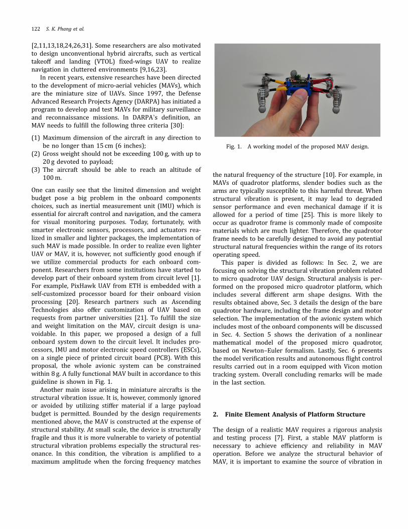
One can easily see that the limited dimension and weightbudget pose a big problem in the onboard componentschoices, such as inertial measurement unit (IMU) which isessential for aircraft control and navigation, and the camerafor visual monitoring purposes. Today, fortunately, withsmarter electronic sensors, processors, and actuators rea-lized in smaller and lighter packages, the implementation ofsuch MAV is made possible. In order to realize even lighterUAV or MAV, it is, however, not sufficiently good enough ifwe utilize commercial products for each onboard com-ponent. Researchers from some institutions have started todevelop part of their onboard system from circuit level [1].For example, PixHawk UAV from ETH is embedded with aself-customized processor board for their onboard visionprocessing [20]. Research partners such as AscendingTechnologies also offer customization of UAV based onrequests from partner universities [21]. To fulfill the sizeand weight limitation on the MAV, circuit design is una-voidable. In this paper, we proposed a design of a fullonboard system down to the circuit level. It includes pro-cessors, IMU and motor electronic speed controllers (ESCs),on a single piece of printed circuit board (PCB). With thisproposal, the whole avionic system can be constrainedwithin 8 g. A fully functional MAV built in accordance to thisguideline is shown in Fig. 1.
Another main issue arising in miniature aircrafts is thestructural vibration issue. It is, however, commonly ignoredor avoided by utilizing stiffer material if a large payloadbudget is permitted. Bounded by the design requirementsmentioned above, the MAV is constructed at the expense ofstructural stability. At small scale, the device is structurallyfragile and thus it is more vulnerable to variety of potentialstructural vibration problems especially the structural res-onance. In this condition, the vibration is amplified to amaximum amplitude when the forcing frequency matches
the natural frequency of the structure [10]. For example, inMAVs of quadrotor platforms, slender bodies such as thearms are typically susceptible to this harmful threat. Whenstructural vibration is present, it may lead to degradedsensor performance and even mechanical damage if it isallowed for a period of time [25]. This is more likely tooccur as quadrotor frame is commonly made of compositematerials which are much lighter. Therefore, the quadrotorframe needs to be carefully designed to avoid any potentialstructural natural frequencies within the range of its rotorsoperating speed.
This paper is divided as follows: In Sec. 2, we arefocusing on solving the structural vibration problem relatedto micro quadrotor UAV design. Structural analysis is per-formed on the proposed micro quadrotor platform, whichincludes several different arm shape designs. With theresults obtained above, Sec. 3 details the design of the barequadrotor hardware, including the frame design and motorselection. The implementation of the avionic system whichincludes most of the onboard components will be discussedin Sec. 4. Section 5 shows the derivation of a nonlinearmathematical model of the proposed micro quadrotor,based on Newton–Euler formalism. Lastly, Sec. 6 presentsthe model verification results and autonomous flight controlresults carried out in a room equipped with Vicon motiontracking system. Overall concluding remarks will be madein the last section.
2. Finite Element Analysis of Platform Structure
The design of a realistic MAV requires a rigorous analysisand testing process [7]. First, a stable MAV platform isnecessary to achieve efficiency and reliability in MAVoperation. Before we analyze the structural behavior ofMAV, it is important to examine the source of vibration in
Fig. 1. A working model of the proposed MAV design.
122 S. K. Phang et al.
April 9, 2014 10:04:11am WSPC/284-US 1450008 ISSN: 2301-3850FA1
the aircraft design. Several important sources of vibrationon helicopter are identified by Cai et al. [6] and Ceruti et al.[8]. Elsewhere, a comprehensive vibration analysis of theUAV helicopter is pursued by Plasencia et al. [28]. In theMAV environment, the structural components may vibratedue to mechanical and aerodynamic effects. Looking at theconfiguration of a quadrotor, the major contributiontowards the vibration issue is attributed to the enginepowered rotating rotors. Mounted on the tip of the quad-rotor arms, these rotors create a periodic excitation whichcaused vibration. To conduct fast and reliable structureanalysis, finite element analysis (FEA) via MSC Nastran isused in the present work. Using this approach, it offers greatflexibility to model complex geometries which would beimpossible by taking analytical approach. Discretized intofinite number of elements, the stresses and displacementsof parts and assemblies under internal and external loadscan be calculated. In additional, natural mode analysis isconducted to determine the natural frequencies and modeshapes of the model. This leads to the prediction of reson-ance for the structure and the type of resonance that mayoccur during the MAV flight operation. On the other hand,frequency response analysis is used to determine the dis-placement response of the model when external steady-state oscillatory excitation (simulating rotor rotation) isapplied.
2.1. Vibration frequency analysis
Although the main source of vibration has been identified, itis still a challenging task to investigate the complex inter-actions between structural, inertial and aerodynamic forcesacting on the MAV structure. Therefore, structural analysisis pursued to analyze the structural stiffness in avoiding theresonant problem. As mentioned above, the flexiblecharacteristics of the MAV components, especially thequadrotor arms are frequently exposed to undesired vi-brations. In the design, in order to perform basic maneu-vering, the micro quadrotor is required to have up to 60 gthrust as it is approximately 1.5 times its own weight. Aseach rotor is subjected to a uniform load, each propeller isexpected to provide at least 15 g of thrust. Here, the relativegearbox vibration is neglected as the propeller is directlydriven by the motor. Using the estimated rotor load, theoperating range of the rotor is determined experimentally.Based on the propeller chosen in this design, rotationalspeed below 330 revolutions per second is found to besufficient to provide the required thrust to perform the task.In other words, the 1st mode natural frequency of the air-craft structure must be much larger than 330Hz to avoidresonance.
In the following subsections, natural modes of a fewdifferent frame designs for small scale quadrotor will be
studied systematically by utilizing the commercial softwareMSC Nastran. A few possible material were simulated, suchas plastic, aluminum and carbon fiber. Note that only theresults from the carbon fiber simulation are shown in thispaper as it exhibits the best stiffness against weight ratioamong the chosen materials.
2.2. Single quadrotor arm
Conventionally, a quadrotor UAV consists of four extendedarms attached to a square body which holds the onboardsystem including sensors, processors and receiver. As theload is shared uniformly on each rotor, the structuralanalysis on single quadrotor arm can provide a good insightbefore we analyze the full quadrotor configuration. Thereare many factors that influence the stiffness of the quad-rotor arm, i.e., material, geometric parameter and shape.Under the constraint of weight and size, it is best to analyzea few different types of beam structure.
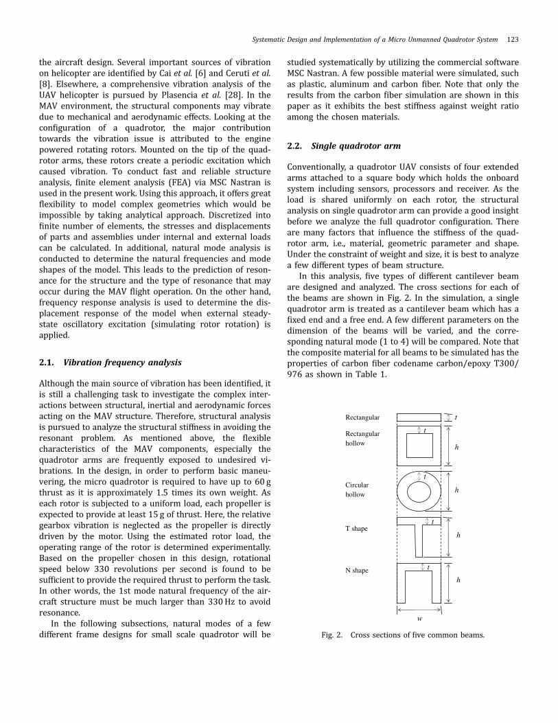
In this analysis, five types of different cantilever beamare designed and analyzed. The cross sections for each ofthe beams are shown in Fig. 2. In the simulation, a singlequadrotor arm is treated as a cantilever beam which has afixed end and a free end. A few different parameters on thedimension of the beams will be varied, and the corre-sponding natural mode (1 to 4) will be compared. Note thatthe composite material for all beams to be simulated has theproperties of carbon fiber codename carbon/epoxy T300/976 as shown in Table 1.
Rectangular
Rectangular hollow
Circular hollow
T shape
N shape
w
t
t
t
h
h
h
h
t
t
Fig. 2. Cross sections of five common beams.
Systematic Design and Implementation of a Micro Unmanned Quadrotor System 123
April 9, 2014 10:04:12am WSPC/284-US 1450008 ISSN: 2301-3850FA1
2.2.1. Length of arm
It is well known that slender bodies are more easilyexposed to vibration, or in other words, shorter beams arestiffer. To verify the relationship between the length of thebeam and its natural mode, rectangular beams (first crosssection in Fig. 2) with different lengths are analyzed in thesimulation. For this analysis, the discrete element employedhas six degrees of freedom per node and all nodes at one ofthe tip are assumed to be fixed by setting all six degrees offreedom to zero. In Table 2, a summary of the Nastrannatural mode analysis results obtained for this study isgiven.
Based on the simulation results, it is evident that naturalfrequencies for all first four modes increased when thestructure is shorter. In general, beams of other shapes showsimilar behavior and thus the results are trivial and not tobe included in this paper. Intuitively, the quadrotor arms arestructurally more stable and resonance at low frequenciescan be avoided if it is shorter. Given the restriction on theminimum length between rotor and mass center, an opti-mum length of quadrotor arm is desired. This is to ensurethe aerodynamic interferences between the rotors could beminimized. Therefore, a minimum length of the quadrotorarms is prescribed to be twice of the rotor radius.
2.2.2. Thickness of beam
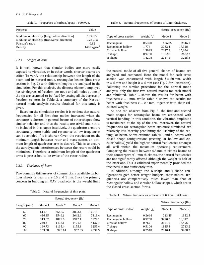
Two common thicknesses of commercially available carbonfiber sheets or beams are 0.5 and 1mm. Since the primaryconcern in building an MAV quadrotor is the weight limit,
the natural mode of all five general shapes of beams areanalyzed and compared. Here, the model for each crosssection was constructed with length l ¼ 60mm, widthw ¼ 6mm and height h ¼ 6mm (see Fig. 2 for illustration).Following the similar procedure for the normal modeanalysis, only the first two natural modes for each modelare tabulated. Table 3 shows the results for beam withthickness t ¼ 1mm, while Table 4 shows the results forbeam with thickness t ¼ 0:5mm, together with their cal-culated weight.
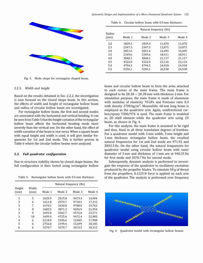
As one can observe from Fig. 3, the first and secondmode shapes for rectangular beam are associated withvertical bending. In this condition, the vibration amplitudeis maximized at the tip of the arm. Moreover, the naturalfrequencies for rectangular beam structure simulated arerelatively low, thereby prohibiting the usability of the rec-tangular beam. As we examine Tables 3 and 4, beams withclosed shape configurations (rectangular hollow and cir-cular hollow) yield the highest natural frequencies amongstall, well within the maximum operating requirement.Comparing the results between 0.5mm thickness beams totheir counterpart of 1mm thickness, the natural frequenciesare not significantly affected although the weight is half ofthe latter one. This is validated experimentally, provided thethickness is not sufficiently thin.
In addition, although the N-shape and T-shape con-figurations give better weight budgets, their natural fre-quencies are comparatively much lower than that ofrectangular hollow and circular hollow shapes, which are inthe closed cross section forms.
Table 1. Properties of carbon/epoxy T300/976.
Property Value
Modulus of elasticity (longitudinal direction) 135 GPaModulus of elasticity (transverse direction) 9.24 GPaPoisson's ratio 0.32Density 1480 kg/m3
April 9, 2014 10:04:14am WSPC/284-US 1450008 ISSN: 2301-3850FA1
2.2.3. Width and height
Based on the results obtained in Sec. 2.2.2, the investigationis now focused on the closed shape beam. In this section,the effects of width and height of rectangular hollow beamand radius of circular hollow beam are investigated.
For rectangular hollow beam, the first and second modesare associated with the horizontal and vertical bending. It canbe seen fromTable5 that theheight variationof the rectangularhollow beam affects the horizontal bending mode moreseverely than the vertical one. On the other hand, the effect ofwidth variation of the beam is vice versa. When a square beamwith equal height and width is used, it will give similar fre-quencies for 1st and 2nd mode. This is further proven inTable 6 where the circular hollow beams were analyzed.
2.3. Full quadrotor configuration
Due to structure stability shown by closed shape beams, thefull configuration is then tested using rectangular hollow
beam and circular hollow beam to form the arms attachedto each corner of the main frame. The main frame isdesigned to be 28:28� 28:28mm with thickness 2mm. Forsimulation purpose, the main frame is made of aluminumwith modulus of elasticity 70 GPa and Poissons ratio 0.3with density 2700 kg/m3. Meanwhile, 60mm long beam isemployed as the quadrotor arm. Again, unidirectional car-bon/epoxy T300/976 is used. The main frame is modeledas 2D shell element while the quadrotor arm using 1Dbeam, as shown in Fig. 4.
For this analysis, the main frame is assumed to be rigidand thus, fixed in all three translation degrees of freedom.For a quadrotor model with 3mm width, 3mm height and1mm thickness rectangular hollow beam, the resultednatural frequencies for 1st and 2nd mode are 971.92 and5843.3 Hz. On the other hand, the natural frequencies forquadrotor model using circular hollow beam with outerdiameter of 3mm and thickness of 1mm are at 940.35Hzfor first mode and 5070.7Hz for second mode.
Subsequently, dynamic analysis is performed to investi-gate the response of the quadrotor to oscillatory excitationproduced by the propeller blades. To simulate 50 g of thrustfrom the propellers, 0.1225N force is applied on each armof the quadrotor. The analysis is performed over frequency
Fig. 3. Mode shape for rectangular shaped beam.
Table 5. Rectangular hollow beam with 0.5mm thickness.
Fig. 4. Quadrotor model with rectangular hollow beams.
Systematic Design and Implementation of a Micro Unmanned Quadrotor System 125
April 9, 2014 10:04:15am WSPC/284-US 1450008 ISSN: 2301-3850FA1
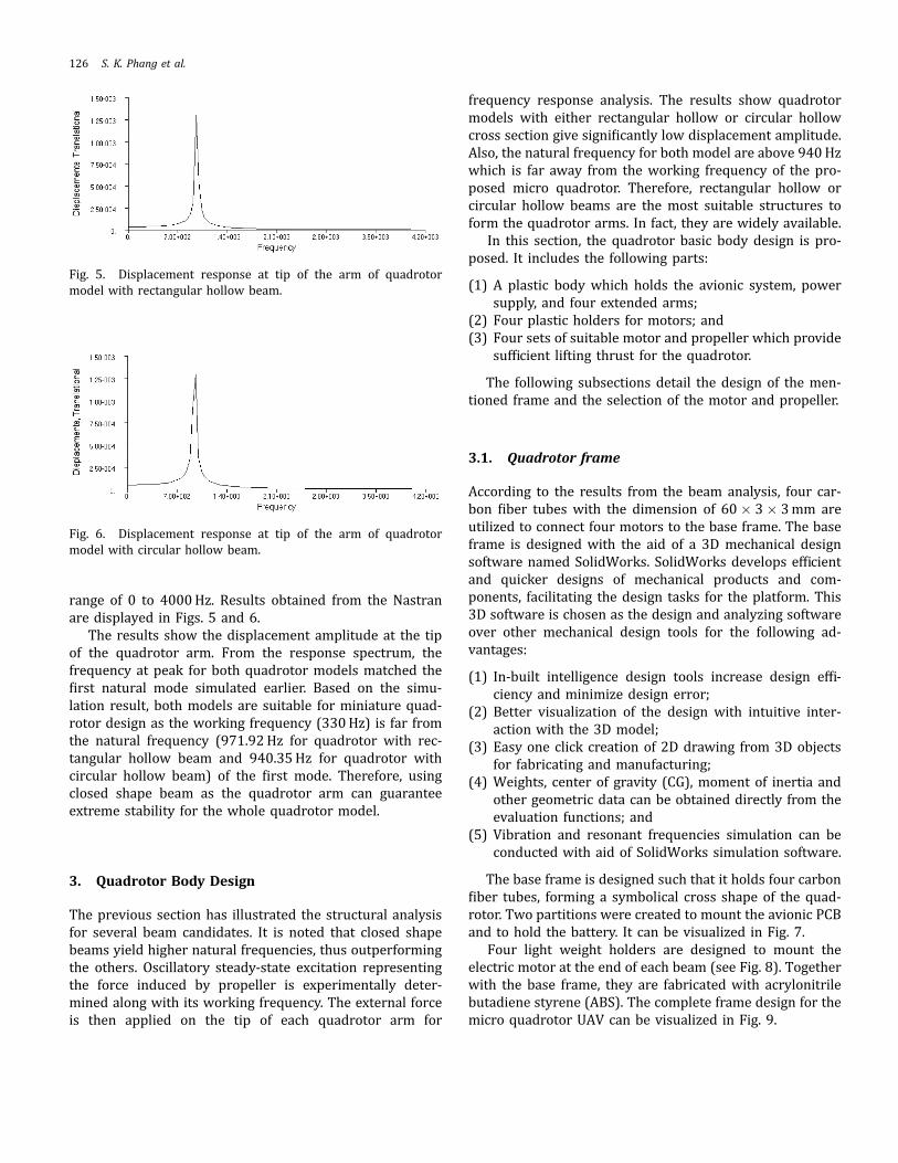
range of 0 to 4000Hz. Results obtained from the Nastranare displayed in Figs. 5 and 6.
The results show the displacement amplitude at the tipof the quadrotor arm. From the response spectrum, thefrequency at peak for both quadrotor models matched thefirst natural mode simulated earlier. Based on the simu-lation result, both models are suitable for miniature quad-rotor design as the working frequency (330Hz) is far fromthe natural frequency (971.92Hz for quadrotor with rec-tangular hollow beam and 940.35Hz for quadrotor withcircular hollow beam) of the first mode. Therefore, usingclosed shape beam as the quadrotor arm can guaranteeextreme stability for the whole quadrotor model.
3. Quadrotor Body Design
The previous section has illustrated the structural analysisfor several beam candidates. It is noted that closed shapebeams yield higher natural frequencies, thus outperformingthe others. Oscillatory steady-state excitation representingthe force induced by propeller is experimentally deter-mined along with its working frequency. The external forceis then applied on the tip of each quadrotor arm for
frequency response analysis. The results show quadrotormodels with either rectangular hollow or circular hollowcross section give significantly low displacement amplitude.Also, the natural frequency for both model are above 940Hzwhich is far away from the working frequency of the pro-posed micro quadrotor. Therefore, rectangular hollow orcircular hollow beams are the most suitable structures toform the quadrotor arms. In fact, they are widely available.
In this section, the quadrotor basic body design is pro-posed. It includes the following parts:
(1) A plastic body which holds the avionic system, powersupply, and four extended arms;
(2) Four plastic holders for motors; and(3) Four sets of suitable motor and propeller which provide
sufficient lifting thrust for the quadrotor.
The following subsections detail the design of the men-tioned frame and the selection of the motor and propeller.
3.1. Quadrotor frame
According to the results from the beam analysis, four car-bon fiber tubes with the dimension of 60� 3� 3mm areutilized to connect four motors to the base frame. The baseframe is designed with the aid of a 3D mechanical designsoftware named SolidWorks. SolidWorks develops efficientand quicker designs of mechanical products and com-ponents, facilitating the design tasks for the platform. This3D software is chosen as the design and analyzing softwareover other mechanical design tools for the following ad-vantages:
(2) Better visualization of the design with intuitive inter-action with the 3D model;
(3) Easy one click creation of 2D drawing from 3D objectsfor fabricating and manufacturing;
(4) Weights, center of gravity (CG), moment of inertia andother geometric data can be obtained directly from theevaluation functions; and
(5) Vibration and resonant frequencies simulation can beconducted with aid of SolidWorks simulation software.
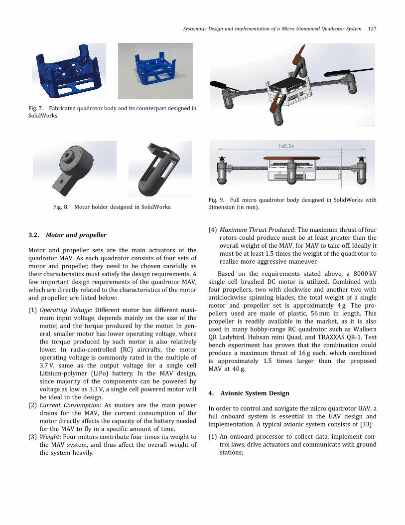
The base frame is designed such that it holds four carbonfiber tubes, forming a symbolical cross shape of the quad-rotor. Two partitions were created to mount the avionic PCBand to hold the battery. It can be visualized in Fig. 7.
Four light weight holders are designed to mount theelectric motor at the end of each beam (see Fig. 8). Togetherwith the base frame, they are fabricated with acrylonitrilebutadiene styrene (ABS). The complete frame design for themicro quadrotor UAV can be visualized in Fig. 9.
Fig. 5. Displacement response at tip of the arm of quadrotormodel with rectangular hollow beam.
Fig. 6. Displacement response at tip of the arm of quadrotormodel with circular hollow beam.
126 S. K. Phang et al.
April 9, 2014 10:04:17am WSPC/284-US 1450008 ISSN: 2301-3850FA1
3.2. Motor and propeller
Motor and propeller sets are the main actuators of thequadrotor MAV. As each quadrotor consists of four sets ofmotor and propeller, they need to be chosen carefully astheir characteristics must satisfy the design requirements. Afew important design requirements of the quadrotor MAV,which are directly related to the characteristics of the motorand propeller, are listed below:
(1) Operating Voltage: Different motor has different maxi-mum input voltage, depends mainly on the size of themotor, and the torque produced by the motor. In gen-eral, smaller motor has lower operating voltage, wherethe torque produced by such motor is also relativelylower. In radio-controlled (RC) aircrafts, the motoroperating voltage is commonly rated in the multiple of3.7 V, same as the output voltage for a single cellLithium-polymer (LiPo) battery. In the MAV design,since majority of the components can be powered byvoltage as low as 3.3 V, a single cell powered motor willbe ideal to the design.
(2) Current Consumption: As motors are the main powerdrains for the MAV, the current consumption of themotor directly affects the capacity of the battery neededfor the MAV to fly in a specific amount of time.
(3) Weight: Four motors contribute four times its weight tothe MAV system, and thus affect the overall weight ofthe system heavily.
(4) Maximum Thrust Produced: The maximum thrust of fourrotors could produce must be at least greater than theoverall weight of the MAV, for MAV to take-off. Ideally itmust be at least 1.5 times the weight of the quadrotor torealize more aggressive maneuver.
Based on the requirements stated above, a 8000 kVsingle cell brushed DC motor is utilized. Combined withfour propellers, two with clockwise and another two withanticlockwise spinning blades, the total weight of a singlemotor and propeller set is approximately 4 g. The pro-pellers used are made of plastic, 56mm in length. Thispropeller is readily available in the market, as it is alsoused in many hobby-range RC quadrotor such as WalkeraQR Ladybird, Hubsan mini Quad, and TRAXXAS QR-1. Testbench experiment has proven that the combination couldproduce a maximum thrust of 16 g each, which combinedis approximately 1.5 times larger than the proposedMAV at 40 g.
4. Avionic System Design
In order to control and navigate the micro quadrotor UAV, afull onboard system is essential in the UAV design andimplementation. A typical avionic system consists of [33]:
(1) An onboard processor to collect data, implement con-trol laws, drive actuators and communicate with groundstations;
Fig. 7. Fabricated quadrotor body and its counterpart designed inSolidWorks.
Fig. 8. Motor holder designed in SolidWorks.Fig. 9. Full micro quadrotor body designed in SolidWorks withdimension (in mm).
Systematic Design and Implementation of a Micro Unmanned Quadrotor System 127
April 9, 2014 10:04:18am WSPC/284-US 1450008 ISSN: 2301-3850FA1
(2) An IMU to measure the attitudes of the vehicles;(3) A good communication system to provide communi-
cation link with ground stations; and(4) Power supply system sufficient to power up the whole
UAV for a respectable duration.
Conventionally, for a UAV with higher payload limit, theonboard components, such as microprocessor, IMU, radioreceiver, and the servo controller, are usually chosen fromthe commercially available products [27,32]. However, inthe micro quadrotor design, the placement of these com-ponents need to be further optimized to reduce weight. Inthis section, a single PCB design incorporating the micro-processor, IMU, and motor speed controllers is proposed.The overall system architecture for the PCB design is shownin Fig. 10.
4.1. Microprocessor
In avionics, processor is the crux of the entire system.Within this compact MAV design, the functions of the pro-cessor include: (1) collecting data from IMU sensor viaserial port; (2) receiving command from the receiver in theform of pulse position modulation (PPM) signal; (3)decoding and analyzing data; (4) implementing flight con-trol algorithms; (5) forwarding control signals in the formof pulse width modulation (PWM) signal to ESC; and (6)sending logged data to the logger via the serial port.
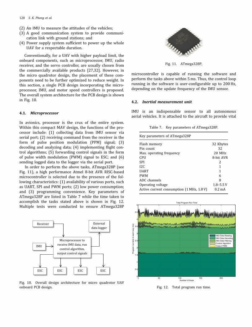
In order to perform the above tasks, ATmega328P (seeFig. 11), a high performance Atmel 8-bit AVR RISC-basedmicrocontroller is selected due to the presence of the fol-lowing characteristics: (1) availability of various ports, suchas UART, SPI and PWM ports; (2) low power consumption;and (3) programming convenience. Key parameters ofATmega328P are listed in Table 7 while the time taken toaccomplish the tasks stated above is shown in Fig. 12.Multiple tests were conducted to ensure ATmega328P
microcontroller is capable of running the software andperform the tasks above within 5ms. Thus, the control looprunning in the software is user-configurable up to 200Hz,depending on the update frequency of the IMU sensor.
4.2. Inertial measurement unit
IMU is an indispensable sensor to all autonomousaerial vehicles. It is attached to the aircraft to provide vital
IMU Data ReadingIMU Data DecodingIMU Data FilteringControl AlgorithmOutput PWM
Fig. 12. Total program run time.
Table 7. Key parameters of ATmega328P.
Key parameters of ATmega328P
Flash memory 32 KbytesPin count 32Max. operating frequency 20 MHzCPU 8-bit AVRSPI 2I2C 1UART 1PWM 6ADC channels 8Operating voltage 1.8–5.5 VActive current consumption (1MHz, 1.8 V) 0.2mA
128 S. K. Phang et al.
April 9, 2014 10:04:42am WSPC/284-US 1450008 ISSN: 2301-3850FA1
real-time motion data such as accelerations, angular rates,and magnetic values. In addition, 3-axis Euler anglesmeasurements are necessary for aircraft orientation control.However, IMU does not necessarily need to provide angularmeasurement of the aircraft as it can be estimated using anextended Kalman filter (EKF) [15] or complimentary filter-ing. The primary disadvantage of these filters is — they arecomputationally intensive, which add extra burden on theonboard AVRmicroprocessor. One of the solutions is to selecta small, light yet powerful IMU with in-built EKF algorithm.
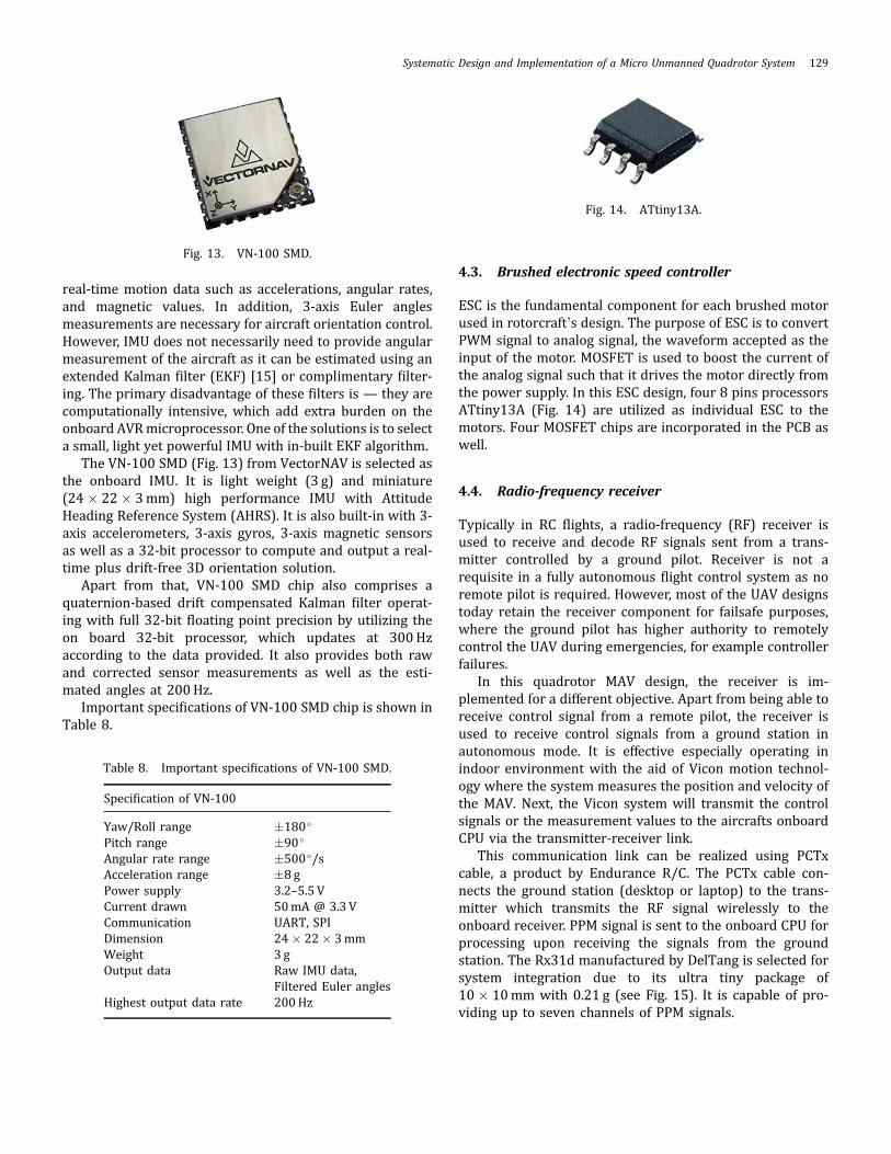
The VN-100 SMD (Fig. 13) from VectorNAV is selected asthe onboard IMU. It is light weight (3 g) and miniature(24� 22� 3mm) high performance IMU with AttitudeHeading Reference System (AHRS). It is also built-in with 3-axis accelerometers, 3-axis gyros, 3-axis magnetic sensorsas well as a 32-bit processor to compute and output a real-time plus drift-free 3D orientation solution.
Apart from that, VN-100 SMD chip also comprises aquaternion-based drift compensated Kalman filter operat-ing with full 32-bit floating point precision by utilizing theon board 32-bit processor, which updates at 300Hzaccording to the data provided. It also provides both rawand corrected sensor measurements as well as the esti-mated angles at 200Hz.
Important specifications of VN-100 SMD chip is shown inTable 8.
4.3. Brushed electronic speed controller
ESC is the fundamental component for each brushed motorused in rotorcraft's design. The purpose of ESC is to convertPWM signal to analog signal, the waveform accepted as theinput of the motor. MOSFET is used to boost the current ofthe analog signal such that it drives the motor directly fromthe power supply. In this ESC design, four 8 pins processorsATtiny13A (Fig. 14) are utilized as individual ESC to themotors. Four MOSFET chips are incorporated in the PCB aswell.
4.4. Radio-frequency receiver
Typically in RC flights, a radio-frequency (RF) receiver isused to receive and decode RF signals sent from a trans-mitter controlled by a ground pilot. Receiver is not arequisite in a fully autonomous flight control system as noremote pilot is required. However, most of the UAV designstoday retain the receiver component for failsafe purposes,where the ground pilot has higher authority to remotelycontrol the UAV during emergencies, for example controllerfailures.
In this quadrotor MAV design, the receiver is im-plemented for a different objective. Apart from being able toreceive control signal from a remote pilot, the receiver isused to receive control signals from a ground station inautonomous mode. It is effective especially operating inindoor environment with the aid of Vicon motion technol-ogy where the system measures the position and velocity ofthe MAV. Next, the Vicon system will transmit the controlsignals or the measurement values to the aircrafts onboardCPU via the transmitter-receiver link.
This communication link can be realized using PCTxcable, a product by Endurance R/C. The PCTx cable con-nects the ground station (desktop or laptop) to the trans-mitter which transmits the RF signal wirelessly to theonboard receiver. PPM signal is sent to the onboard CPU forprocessing upon receiving the signals from the groundstation. The Rx31d manufactured by DelTang is selected forsystem integration due to its ultra tiny package of10� 10mm with 0.21 g (see Fig. 15). It is capable of pro-viding up to seven channels of PPM signals.
Fig. 13. VN-100 SMD.
Table 8. Important specifications of VN-100 SMD.
Specification of VN-100
Yaw/Roll range �180�
Pitch range �90�
Angular rate range �500�/sAcceleration range �8 gPower supply 3.2–5.5 VCurrent drawn 50mA @ 3.3 VCommunication UART, SPIDimension 24� 22� 3mmWeight 3 gOutput data Raw IMU data,
Filtered Euler anglesHighest output data rate 200Hz
Fig. 14. ATtiny13A.
Systematic Design and Implementation of a Micro Unmanned Quadrotor System 129
April 9, 2014 10:04:45am WSPC/284-US 1450008 ISSN: 2301-3850FA1
4.5. Data logger
Important flight data such as state variables of an UAV arerecorded for post flight observation and analysis, thusrequiring a data logger. In order to fit into this MAV design,the data logger needs to be small, light and reliable to carryout this task. An open source data logger from SparkfunOpenLog (see Fig. 16) is utilized for this purpose. OpenLogweighs only 1.70 g and fits perfectly into the MAV design. Itstarts logging any serial data up to 115,200 baud rate to themicro SD card upon powered up. In addition, Sparkfunprovides OpenLog firmware and design files which can beredesigned into the main PCB of the MAV.
4.6. Power supply
The main consideration in designing the power supply is tomeet the overall system and flight duration requirements.The choice of power supply is important as it usually con-stitutes approximately 30% of the overall weight of theMAV, and the power needed to lift the MAV will beincreased due to its own weight. As all onboard componentscan be powered up with 3.3 V, a single cell LiPo battery withcurrent capacity of 360mAh is utilized to power the avio-nics and to drive the motors (see Fig. 17). A 3.3 V regulatoris included to provide a clean voltage to the components, as
a single cell LiPo battery has output vary from 4.2 V whenfully charged to lower than 3.4 V when it is used up. Thebattery is as light as 10 g and is able to provide enoughenergy for an 8-min flight duration.
4.7. PCB layout design
In this subsection, the design process of the PCB for theavionic system of the micro quadrotor UAV will be descri-bed in detail. Among the five components to be included tothe avionic system, the IMU, flight control CPU and fourESCs will be incorporated into the design, while the receiverand the logger will be attached to the designed PCB. Ageneral guideline to design avionics PCB for quadrotor MAVusing Altium Designer is as follows:
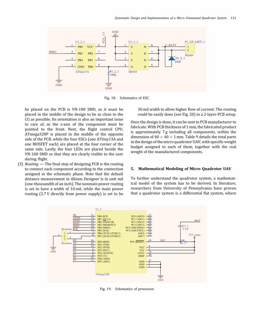
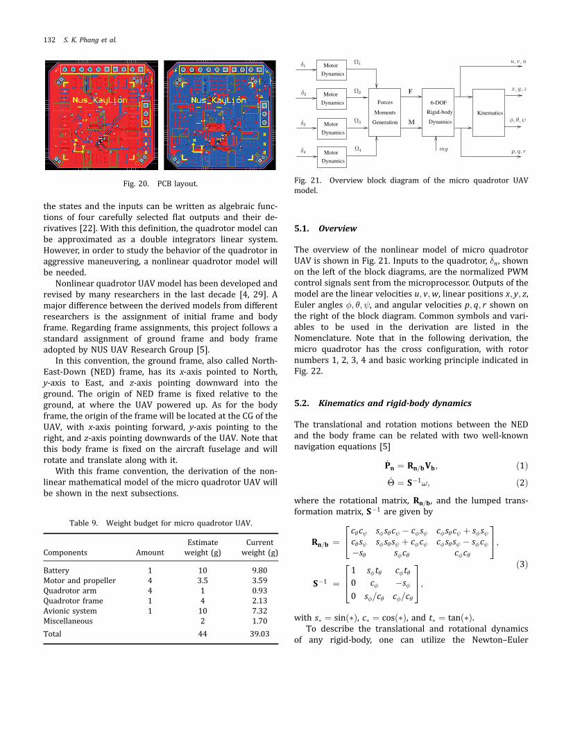
(1) Schematic design — A schematic diagram of the designmust be drawn in Altium Designer with all the com-ponents needed, i.e., one ATmega328P, one VN-100SMD, four ATtiny13As, and four MOSFETs. Also, fourstatus indication LEDs are introduced to the design,with one of them connected directly to the powersupply as the power indicator, while the rest of themconnected to the general output port of the flight con-trol CPU for user configurable purposes. As all thesecomponents can be powered up with 3.3 V, a voltageregulator with 3.3 V output is included. Connectionsbetween each of the components can be viewed in theschematics of ESC (see Fig. 18) and the microprocessor(see Fig. 19).
(2) Layout assignment — The layout of the components onthe PCB is important as to reduce the electromagneticinterference between the components. To satisfy thedimension and weight constraints, a maximum of4� 4 cm PCB layout is imposed. The first component to
Fig. 15. DelTang Rx31d receiver.
Fig. 16. Sparkfun OpenLog.
Fig. 17. Power supply for the MAV.
130 S. K. Phang et al.
April 9, 2014 10:04:45am WSPC/284-US 1450008 ISSN: 2301-3850FA1
be placed on the PCB is VN-100 SMD, as it must beplaced in the middle of the design to be as close to theCG as possible. Its orientation is also an important issueto care of, as the x-axis of the component must bepointed to the front. Next, the flight control CPU,ATmega328P is placed in the middle of the oppositeside of the PCB, while the four ESCs (one ATtiny13A andone MOSFET each) are placed at the four corner of thesame side. Lastly, the four LEDs are placed beside theVN-100 SMD so that they are clearly visible to the userduring flight.
(3) Routing — The final step of designing PCB is the routingto connect each component according to the connectionassigned in the schematic phase. Note that the defaultdistance measurement in Altium Designer is in unit mil(one-thousandth of an inch). The nonmain power routingis set to have a width of 10mil, while the main powerrouting (3.7 V directly from power supply) is set to be
30mil width to allow higher flow of current. The routingcould be easily done (see Fig. 20) in a 2-layer-PCB setup.
Once the design is done, it can be sent to PCBmanufacturer tofabricate.With PCB thickness of 1mm, the fabricated productis approximately 7 g including all components, within thedimension of 40� 40� 1mm. Table 9 details the total partsin the design of themicroquadrotorUAV,with specificweightbudget assigned to each of them, together with the realweight of the manufactured components.
5. Mathematical Modeling of Micro Quadrotor UAV
To further understand the quadrotor system, a mathemat-ical model of the system has to be derived. In literature,researchers from University of Pennsylvania have proventhat a quadrotor system is a differential flat system, where
D1_S_1DNP
100KR1_2_1
VCC8
PB27
PB16
PB05
PB51
PB32
PB43
GND4
U1_2_1
ATtiny13A
D8
D7
D6
D5
S1
S2
S3
G4
U1_1_1
SI4410
12
P1_UP_LEFT_1
Header
V_BATT
GND
GND
MISO
GND
VC
C_3
.3
Fig. 18. Schematics of ESC.
PC6 (RESET)29
PD0 (RXD)30
PD1 (TXD)31
PD2 (INT0)32
PD3 (INT1)1
PD4 (XCK/T0)2
VCC6
GND5
PB6 (XTAL1/TOSC1)7
PB7 (XTAL2/TOSC2)8
PD5 (T1)9
PD6 (AIN0)10
PD7 (AIN1)11
PB0 (ICP)12
PB1 (OC1A)13
PB2 (SS/OC1B)14
PB3 (MOSI/OC2)15
PB4 (MISO)16
PB5 (SCK)17
AVCC18
AREF20
GND21
PC0 (ADC0)23
PC1 (ADC1)24
PC2 (ADC2)25
PC3 (ADC3)26
PC4 (ADC4/SDA)27
PC5 (ADC5/SCL)28
GND3
VCC4
ADC619
ADC722
U1_3
ATmega328P
10KR1_1
0.1uFC1_1
#RST
GND
D8PWM0PWM1MOSIMISOSCK
GND
RXTX
VCC_mega
RST
11
22
33
Resonator_1
Resonator
HPD4D5D6D7
D2
Fig. 19. Schematics of processor.
Systematic Design and Implementation of a Micro Unmanned Quadrotor System 131
April 9, 2014 10:04:55am WSPC/284-US 1450008 ISSN: 2301-3850FA1
the states and the inputs can be written as algebraic func-tions of four carefully selected flat outputs and their de-rivatives [22]. With this definition, the quadrotor model canbe approximated as a double integrators linear system.However, in order to study the behavior of the quadrotor inaggressive maneuvering, a nonlinear quadrotor model willbe needed.
Nonlinear quadrotor UAV model has been developed andrevised by many researchers in the last decade [4, 29]. Amajor difference between the derived models from differentresearchers is the assignment of initial frame and bodyframe. Regarding frame assignments, this project follows astandard assignment of ground frame and body frameadopted by NUS UAV Research Group [5].
In this convention, the ground frame, also called North-East-Down (NED) frame, has its x-axis pointed to North,y-axis to East, and z-axis pointing downward into theground. The origin of NED frame is fixed relative to theground, at where the UAV powered up. As for the bodyframe, the origin of the frame will be located at the CG of theUAV, with x-axis pointing forward, y-axis pointing to theright, and z-axis pointing downwards of the UAV. Note thatthis body frame is fixed on the aircraft fuselage and willrotate and translate along with it.
With this frame convention, the derivation of the non-linear mathematical model of the micro quadrotor UAV willbe shown in the next subsections.
5.1. Overview
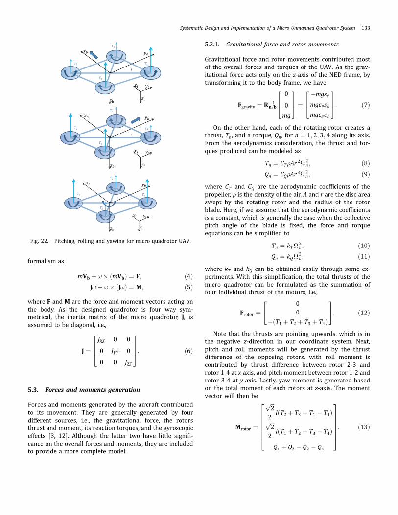
The overview of the nonlinear model of micro quadrotorUAV is shown in Fig. 21. Inputs to the quadrotor, �n, shownon the left of the block diagrams, are the normalized PWMcontrol signals sent from the microprocessor. Outputs of themodel are the linear velocities u; v;w, linear positions x; y; z,Euler angles �; �; , and angular velocities p; q; r shown onthe right of the block diagram. Common symbols and vari-ables to be used in the derivation are listed in theNomenclature. Note that in the following derivation, themicro quadrotor has the cross configuration, with rotornumbers 1, 2, 3, 4 and basic working principle indicated inFig. 22.
5.2. Kinematics and rigid-body dynamics
The translational and rotation motions between the NEDand the body frame can be related with two well-knownnavigation equations [5]
P:n ¼ Rn=bVb; ð1Þ£: ¼ S�1!; ð2Þ
where the rotational matrix, Rn=b, and the lumped trans-formation matrix, S�1 are given by
with s� ¼ sinð�Þ, c� ¼ cosð�Þ, and t� ¼ tanð�Þ.To describe the translational and rotational dynamics
of any rigid-body, one can utilize the Newton–Euler
6-DOF
Rigid-body
Dynamics
Kinematics
Forces
Moments
Generation
Motor
Dynamics
Motor
Dynamics
Motor
Dynamics
Motor
Dynamics
Fig. 21. Overview block diagram of the micro quadrotor UAVmodel.
Table 9. Weight budget for micro quadrotor UAV.
Components AmountEstimateweight (g)
Currentweight (g)
Battery 1 10 9.80Motor and propeller 4 3.5 3.59Quadrotor arm 4 1 0.93Quadrotor frame 1 4 2.13Avionic system 1 10 7.32Miscellaneous 2 1.70
Total 44 39.03
Fig. 20. PCB layout.
132 S. K. Phang et al.
April 9, 2014 10:04:58am WSPC/284-US 1450008 ISSN: 2301-3850FA1
formalism as
mV:b þ !� ðmVbÞ ¼ F; ð4ÞJ!: þ !� ðJ!Þ ¼ M; ð5Þ
where F and M are the force and moment vectors acting onthe body. As the designed quadrotor is four way sym-metrical, the inertia matrix of the micro quadrotor, J, isassumed to be diagonal, i.e.,
J ¼JXX 0 0
0 JYY 0
0 0 JZZ
2664
3775: ð6Þ
5.3. Forces and moments generation
Forces and moments generated by the aircraft contributedto its movement. They are generally generated by fourdifferent sources, i.e., the gravitational force, the rotorsthrust and moment, its reaction torques, and the gyroscopiceffects [3, 12]. Although the latter two have little signifi-cance on the overall forces and moments, they are includedto provide a more complete model.
5.3.1. Gravitational force and rotor movements
Gravitational force and rotor movements contributed mostof the overall forces and torques of the UAV. As the grav-itational force acts only on the z-axis of the NED frame, bytransforming it to the body frame, we have
Fgravity ¼ R�1n=b
0
0
mg
264
375 ¼
�mgs�
mgc�s�
mgc�c�
264
375: ð7Þ
On the other hand, each of the rotating rotor creates athrust, Tn, and a torque, Qn, for n ¼ 1; 2; 3; 4 along its axis.From the aerodynamics consideration, the thrust and tor-ques produced can be modeled as
Tn ¼ CT�Ar2�2
n; ð8ÞQn ¼ CQ�Ar
3�2n; ð9Þ
where CT and CQ are the aerodynamic coefficients of thepropeller, � is the density of the air, A and r are the disc areaswept by the rotating rotor and the radius of the rotorblade. Here, if we assume that the aerodynamic coefficientsis a constant, which is generally the case when the collectivepitch angle of the blade is fixed, the force and torqueequations can be simplified to
Tn ¼ kT�2n; ð10Þ
Qn ¼ kQ�2n; ð11Þ
where kT and kQ can be obtained easily through some ex-periments. With this simplification, the total thrusts of themicro quadrotor can be formulated as the summation offour individual thrust of the motors, i.e.,
Frotor ¼00
�ðT1 þ T2 þ T3 þ T4Þ
24
35: ð12Þ
Note that the thrusts are pointing upwards, which is inthe negative z-direction in our coordinate system. Next,pitch and roll moments will be generated by the thrustdifference of the opposing rotors, with roll moment iscontributed by thrust difference between rotor 2-3 androtor 1-4 at x-axis, and pitch moment between rotor 1-2 androtor 3-4 at y-axis. Lastly, yaw moment is generated basedon the total moment of each rotors at z-axis. The momentvector will then be
Mrotor ¼
ffiffiffi2
p
2lðT2 þ T3 � T1 � T4Þ
ffiffiffi2
p
2lðT1 þ T2 � T3 � T4Þ
Q1 þ Q3 � Q2 � Q4
26666664
37777775: ð13Þ
Fig. 22. Pitching, rolling and yawing for micro quadrotor UAV.
Systematic Design and Implementation of a Micro Unmanned Quadrotor System 133
April 9, 2014 10:05:06am WSPC/284-US 1450008 ISSN: 2301-3850FA1
5.3.2. Reaction torques
Inertia counter torque, which is the reaction torque pro-duced by the change in rotational speed of the rotor, ismodeled as
Mreaction ¼00
�Jrð _1 þ _3 � _2 � _4Þ
264
375: ð14Þ
5.3.3. Gyroscopic effects
Gyroscopic moments, caused by the combination of ro-tations of four propellers and the aircraft's body are com-monly modeled as
Mgyro ¼X4
i¼1
Jr !�0
01
24
35
0@
1Að�1Þ i�i ð15Þ
¼�Jrqð�1 � �2 þ �3 � �4ÞJrpð�1 � �2 þ �3 � �4Þ
0
264
375; ð16Þ
where Jr is the total rotational moment of inertia around thepropeller axis.
5.4. Motor dynamics
A standard DC motor is usually a 2nd-order system, with oneorder contributed by the electrical dynamics, and anothercontributed by the mechanical dynamics. In most of the DCmotor system, the electrical dynamics is much faster than themechanical counterpart, and therefore we can approximatethe motor dynamics as a first-order system, where its par-ameters, i.e., the steady state gain, km, and time constant, �mcan be obtained experimentally. In frequency domain,
�nðsÞ�nðsÞ
¼ km�msþ 1
; ð17Þ
and in time domain,
_n ¼1�m
½kmð�n � � �nÞ � �n�; ð18Þ
where � �n is the normalized input value right when the motorstarts spinning. Note that in Eqs. (17) and (18), �n is thenormalized input to the motor speed controller, with thefollowing normalization process,
�n ¼un � 1100
840; ð19Þ
where un is the PWM pulse width fed to the ESC in unit �s. Ingeneral, theminimumandmaximumpossible pulsewidths tothe ESC are at 1100�s and 1940�s, respectively.
5.5. Parameters identification and verification
Based on the model derived in the previous subsections,several parameters are to be identified with methods ofdirect measurement, software approximation and testbench experiments. Table 10 shows the parameters to beidentified and its physical meaning.
5.5.1. Direct measurements
Some parameters can be directly measured by a weighingbalance and ruler, as follows:
m ¼ 0:045 kg; ð20Þl ¼ 0:058m; ð21Þ
where m is the gross weight and l is the beam length. Thegravitational acceleration can be calculated given the lati-tude of Singapore as follows,
g � 9:781m=s2: ð22Þ
5.5.2. Software approximations
With the aid of SolidWorks, the tensor and rotating momentof inertia of mechanical parts can be estimated numerically.With exact density and scale to the real physical parts, thetensor moment of inertia of the quadrotor MAV and therotating moment of inertia of the propeller are calculatedwith the mass properties function of SolidWorks:
J ¼3:0738 0 0
0 3:0849 0
0 0 5:9680
264
375� 10�5 kgm2; ð23Þ
Table 10. Parameters to be identified and its physical meaning.
Parameter Physical meaning
g Gravity accelerationm Mass of quadrotorl Distance between rotor and center of gravitykT Rotor thrust constantkQ Rotor torque constantkm Motor steady-state gain�m Motor time constantJXX Moment of inertia of quadrotor along x-axisJYY Moment of inertia of quadrotor along y-axisJZZ Moment of inertia of quadrotor along z-axisJr Rotating moment of inertia of propeller
134 S. K. Phang et al.
April 9, 2014 10:05:09am WSPC/284-US 1450008 ISSN: 2301-3850FA1
Jr ¼ 5:897� 10�8 kgm2: ð24ÞNote that J is diagonal as the designed quadrotor structureis highly symmetric.
5.5.3. Test bench experiments
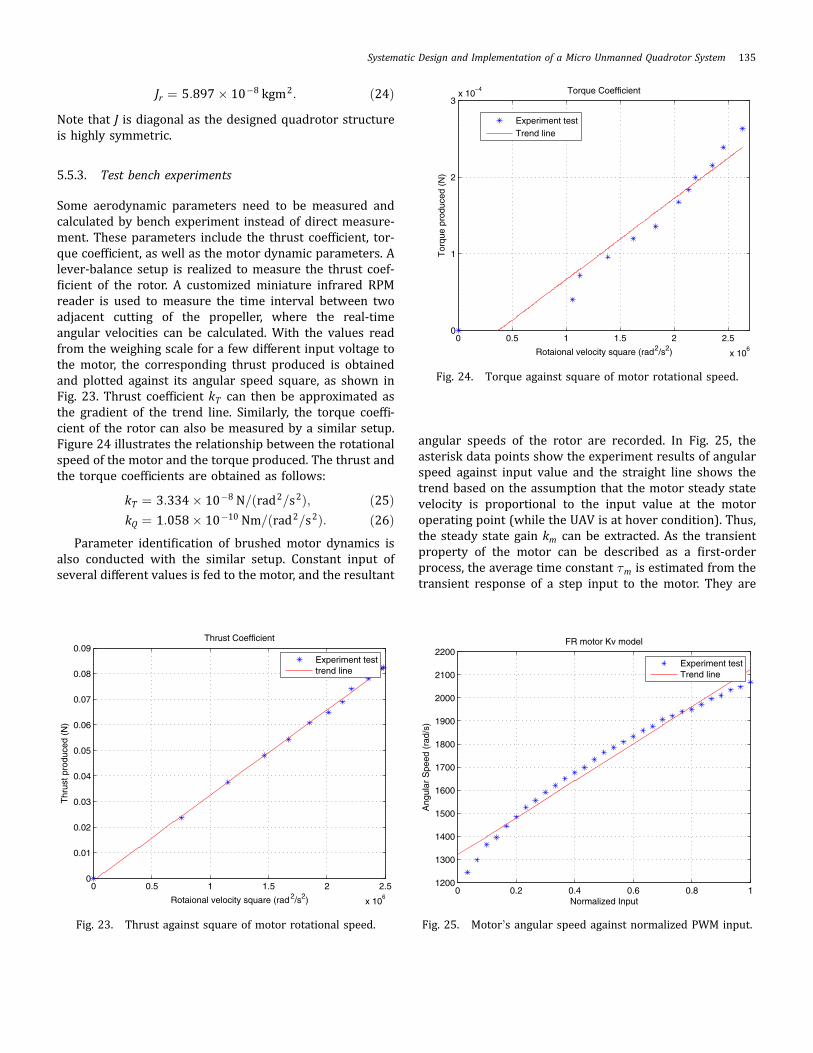
Some aerodynamic parameters need to be measured andcalculated by bench experiment instead of direct measure-ment. These parameters include the thrust coefficient, tor-que coefficient, as well as the motor dynamic parameters. Alever-balance setup is realized to measure the thrust coef-ficient of the rotor. A customized miniature infrared RPMreader is used to measure the time interval between twoadjacent cutting of the propeller, where the real-timeangular velocities can be calculated. With the values readfrom the weighing scale for a few different input voltage tothe motor, the corresponding thrust produced is obtainedand plotted against its angular speed square, as shown inFig. 23. Thrust coefficient kT can then be approximated asthe gradient of the trend line. Similarly, the torque coeffi-cient of the rotor can also be measured by a similar setup.Figure 24 illustrates the relationship between the rotationalspeed of the motor and the torque produced. The thrust andthe torque coefficients are obtained as follows:
Parameter identification of brushed motor dynamics isalso conducted with the similar setup. Constant input ofseveral different values is fed to the motor, and the resultant
angular speeds of the rotor are recorded. In Fig. 25, theasterisk data points show the experiment results of angularspeed against input value and the straight line shows thetrend based on the assumption that the motor steady statevelocity is proportional to the input value at the motoroperating point (while the UAV is at hover condition). Thus,the steady state gain km can be extracted. As the transientproperty of the motor can be described as a first-orderprocess, the average time constant �m is estimated from thetransient response of a step input to the motor. They are
0 0.5 1 1.5 2 2.5
x 106
0
0.01
0.02
0.03
0.04
0.05
0.06
0.07
0.08
0.09
Rotaional velocity square (rad 2/s2)
Thr
ust p
rodu
ced
(N)
Thrust Coefficient
Experiment testtrend line
Fig. 23. Thrust against square of motor rotational speed.
0 0.5 1 1.5 2 2.5
x 106
0
1
2
3x 10
−4
Rotaional velocity square (rad2/s2)
Tor
que
prod
uced
(N
)
Torque Coefficient
Experiment testTrend line
Fig. 24. Torque against square of motor rotational speed.
0 0.2 0.4 0.6 0.8 11200
1300
1400
1500
1600
1700
1800
1900
2000
2100
2200
Normalized Input
Ang
ular
Spe
ed (
rad/
s)
FR motor Kv model
Experiment testTrend line
Fig. 25. Motor's angular speed against normalized PWM input.
Systematic Design and Implementation of a Micro Unmanned Quadrotor System 135
April 9, 2014 10:05:09am WSPC/284-US 1450008 ISSN: 2301-3850FA1
identified as follows:
km ¼ 803:9; ð27Þ�m ¼ 0:0821 s: ð28Þ
Table 11 summarizes the parameters identified in theabove sections.
6. MAV Control
Upon obtaining the mathematical model of the aircraft, asimple yet reliable PID controller is designed and simulatedwith the aid of Simulink in MATLAB.
Generally, the dynamics of a quadrotor without orien-tation stabilizer is too fast even for a skilled man pilot. Thefast dynamic is contributed by the roll and pitch movements,while the yaw movement exhibits a much slower dynamic.
In this section, an orientation controller is described andimplemented to achieve attitude stability of the microquadrotor UAV. The controller is first designed in Simulinkand MATLAB onto the mathematical system derived andestimated in the previous section. Upon obtaining a satis-fying control response in simulation, the controller is thenrealized in the micro quadrotor hardware. The mathemat-ical model is then verified with sinusoidal perturbationinputs.
6.1. Software simulation
In the initial stage of the PID gains tuning, the controller isfirst designed in simulation by adopting the Ziegler–Nicholsmethod, as shown in the steps below:
(1) Set both derivative (Kd) and integrative (Ki) gain tozero, tune proportional gain (Kp) such that simulationresults shows sustained oscillation on all Euler angles.
(2) Record the ultimate proportional gain (Ku) and the os-cillation period (Tu).
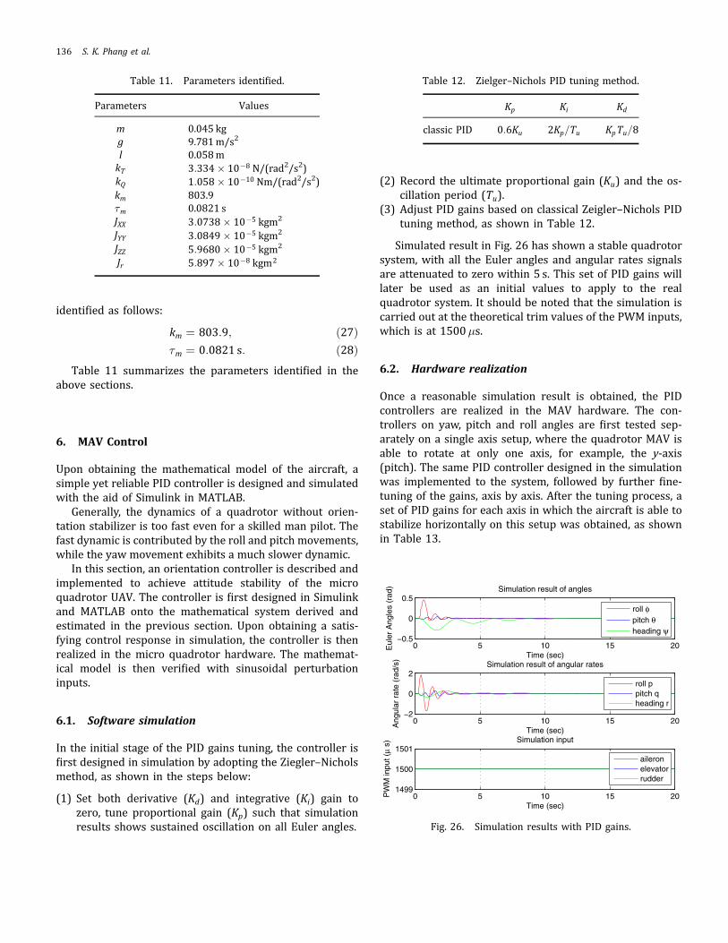
(3) Adjust PID gains based on classical Zeigler–Nichols PIDtuning method, as shown in Table 12.
Simulated result in Fig. 26 has shown a stable quadrotorsystem, with all the Euler angles and angular rates signalsare attenuated to zero within 5 s. This set of PID gains willlater be used as an initial values to apply to the realquadrotor system. It should be noted that the simulation iscarried out at the theoretical trim values of the PWM inputs,which is at 1500�s.
6.2. Hardware realization
Once a reasonable simulation result is obtained, the PIDcontrollers are realized in the MAV hardware. The con-trollers on yaw, pitch and roll angles are first tested sep-arately on a single axis setup, where the quadrotor MAV isable to rotate at only one axis, for example, the y-axis(pitch). The same PID controller designed in the simulationwas implemented to the system, followed by further fine-tuning of the gains, axis by axis. After the tuning process, aset of PID gains for each axis in which the aircraft is able tostabilize horizontally on this setup was obtained, as shownin Table 13.
April 9, 2014 10:05:12am WSPC/284-US 1450008 ISSN: 2301-3850FA1
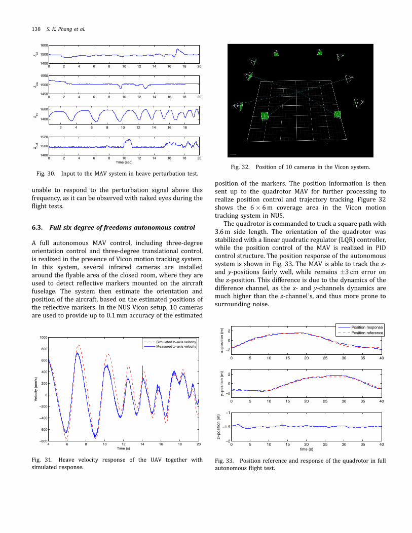
Next, the PID controller is realized in the manufacturedquadrotor MAV codenamed KayLion (Fig. 27). Flight testsare carried out to test the endurance of the vehicle, and toverify the mathematical model derived in the previoussection.
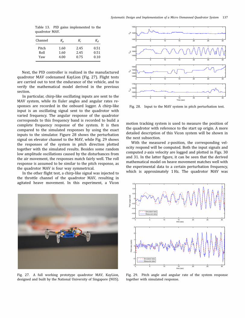
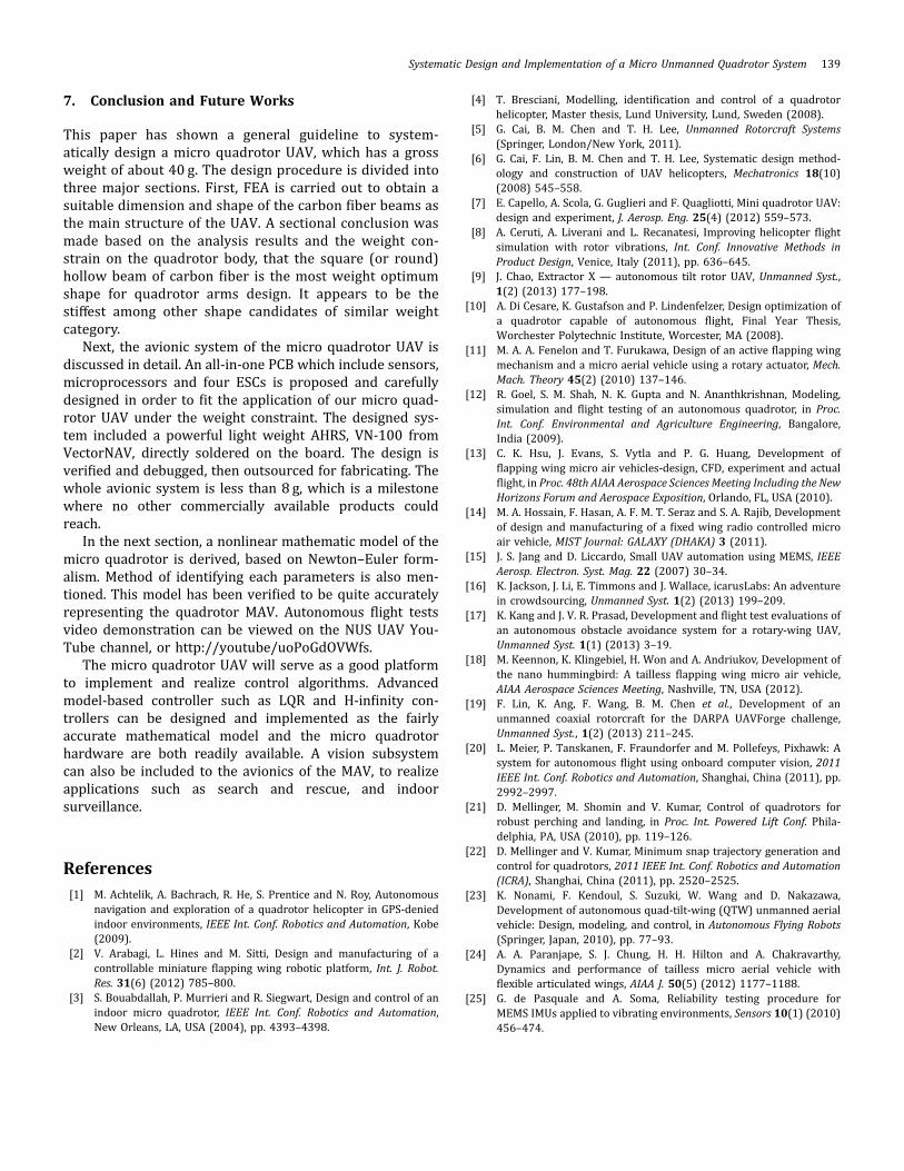
In particular, chirp-like oscillating inputs are sent to theMAV system, while its Euler angles and angular rates re-sponses are recorded in the onboard logger. A chirp-likeinput is an oscillating signal sent to the quadrotor withvaried frequency. The angular response of the quadrotorcorresponds to this frequency band is recorded to build acomplete frequency response of the system. It is thencompared to the simulated responses by using the exactinputs to the simulator. Figure 28 shows the perturbationsignal on elevator channel to the MAV, while Fig. 29 showsthe responses of the system in pitch direction plottedtogether with the simulated results. Besides some randomlow amplitude oscillations caused by the disturbances fromthe air movement, the responses match fairly well. The rollresponse is assumed to be similar to the pitch response, asthe quadrotor MAV is four way symmetrical.
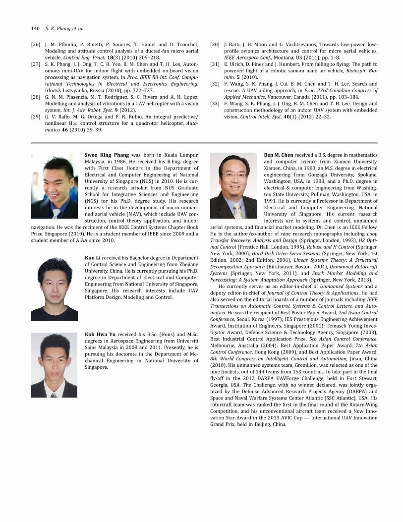
In the other flight test, a chirp-like signal was injected tothe throttle channel of the quadrotor MAV, resulting inagitated heave movement. In this experiment, a Vicon
motion tracking system is used to measure the position ofthe quadrotor with reference to the start up origin. A moredetailed description of this Vicon system will be shown inthe next subsection.
With the measured z-position, the corresponding vel-ocity respond will be computed. Both the input signals andcomputed z-axis velocity are logged and plotted in Figs. 30and 31. In the latter figure, it can be seen that the derivedmathematical model on heave movement matches well withthe experimental data to a certain perturbation frequency,which is approximately 1Hz. The quadrotor MAV was
Table 13. PID gains implemented to thequadrotor MAV.
Fig. 27. A full working prototype quadrotor MAV, KayLion,designed and built by the National University of Singapore (NUS).
0 5 10 15 20 25 301450
1500
1550
δ ail
0 5 10 15 20 25 30
1400
1500
1600
δ ele
0 5 10 15 20 25 30
1400
1450
1500
1550
δ thr
0 5 10 15 20 25 301400
1500
1600
1700
δ rud
Time (sec)
Fig. 28. Input to the MAV system in pitch perturbation test.
0 5 10 15 20 25 30−0.8
−0.6
−0.4
−0.2
0
0.2
0.4
0.6
time (sec)
Pitc
h an
gle
(rad
)
Simulated dataMeasured data
0 5 10 15 20 25 30−3
−2
−1
0
1
2
3
time (sec)
Pitc
h ra
te (
rad/
s)
Simulated dataMeasured data
Fig. 29. Pitch angle and angular rate of the system responsetogether with simulated response.
Systematic Design and Implementation of a Micro Unmanned Quadrotor System 137
April 9, 2014 10:05:14am WSPC/284-US 1450008 ISSN: 2301-3850FA1
unable to respond to the perturbation signal above thisfrequency, as it can be observed with naked eyes during theflight tests.
6.3. Full six degree of freedoms autonomous control
A full autonomous MAV control, including three-degreeorientation control and three-degree translational control,is realized in the presence of Vicon motion tracking system.In this system, several infrared cameras are installedaround the flyable area of the closed room, where they areused to detect reflective markers mounted on the aircraftfuselage. The system then estimate the orientation andposition of the aircraft, based on the estimated positions ofthe reflective markers. In the NUS Vicon setup, 10 camerasare used to provide up to 0.1mm accuracy of the estimated
position of the markers. The position information is thensent up to the quadrotor MAV for further processing torealize position control and trajectory tracking. Figure 32shows the 6� 6m coverage area in the Vicon motiontracking system in NUS.
The quadrotor is commanded to track a square path with3.6m side length. The orientation of the quadrotor wasstabilized with a linear quadratic regulator (LQR) controller,while the position control of the MAV is realized in PIDcontrol structure. The position response of the autonomoussystem is shown in Fig. 33. The MAV is able to track the x-and y-positions fairly well, while remains �3 cm error onthe z-position. This difference is due to the dynamics of thedifference channel, as the x- and y-channels dynamics aremuch higher than the z-channel's, and thus more prone tosurrounding noise.
4 6 8 10 12 14 16 18 20−800
−600
−400
−200
0
200
400
600
800
1000
Time (s)
Vel
ocity
(m
m/s
)
Simulated z−axis velocityMeasured z−axis velocity
Fig. 31. Heave velocity response of the UAV together withsimulated response.
0 5 10 15 20 25 30 35 40
−2
0
2
x−po
sitio
n (m
)
0 5 10 15 20 25 30 35 40
−2
0
2
y−po
sitio
n (m
)
0 5 10 15 20 25 30 35 40−2
−1.5
−1
z−po
sitio
n (m
)
time (s)
Position responsePosition reference
Fig. 33. Position reference and response of the quadrotor in fullautonomous flight test.
0 2 4 6 8 10 12 14 16 18 201400
1500
1600
δ ail
0 2 4 6 8 10 12 14 16 18 201450
1500
1550
δ ele
2 4 6 8 10 12 14 16 18
1400
1600
δ thr
0 2 4 6 8 10 12 14 16 18 201480
1500
1520
δ rud
Time (sec)
Fig. 30. Input to the MAV system in heave perturbation test.Fig. 32. Position of 10 cameras in the Vicon system.
138 S. K. Phang et al.
April 9, 2014 10:05:18am WSPC/284-US 1450008 ISSN: 2301-3850FA1
7. Conclusion and Future Works
This paper has shown a general guideline to system-atically design a micro quadrotor UAV, which has a grossweight of about 40 g. The design procedure is divided intothree major sections. First, FEA is carried out to obtain asuitable dimension and shape of the carbon fiber beams asthe main structure of the UAV. A sectional conclusion wasmade based on the analysis results and the weight con-strain on the quadrotor body, that the square (or round)hollow beam of carbon fiber is the most weight optimumshape for quadrotor arms design. It appears to be thestiffest among other shape candidates of similar weightcategory.
Next, the avionic system of the micro quadrotor UAV isdiscussed in detail. An all-in-one PCB which include sensors,microprocessors and four ESCs is proposed and carefullydesigned in order to fit the application of our micro quad-rotor UAV under the weight constraint. The designed sys-tem included a powerful light weight AHRS, VN-100 fromVectorNAV, directly soldered on the board. The design isverified and debugged, then outsourced for fabricating. Thewhole avionic system is less than 8 g, which is a milestonewhere no other commercially available products couldreach.
In the next section, a nonlinear mathematic model of themicro quadrotor is derived, based on Newton–Euler form-alism. Method of identifying each parameters is also men-tioned. This model has been verified to be quite accuratelyrepresenting the quadrotor MAV. Autonomous flight testsvideo demonstration can be viewed on the NUS UAV You-Tube channel, or http://youtube/uoPoGdOVWfs.
The micro quadrotor UAV will serve as a good platformto implement and realize control algorithms. Advancedmodel-based controller such as LQR and H-infinity con-trollers can be designed and implemented as the fairlyaccurate mathematical model and the micro quadrotorhardware are both readily available. A vision subsystemcan also be included to the avionics of the MAV, to realizeapplications such as search and rescue, and indoorsurveillance.
References[1] M. Achtelik, A. Bachrach, R. He, S. Prentice and N. Roy, Autonomous
navigation and exploration of a quadrotor helicopter in GPS-deniedindoor environments, IEEE Int. Conf. Robotics and Automation, Kobe(2009).
[2] V. Arabagi, L. Hines and M. Sitti, Design and manufacturing of acontrollable miniature flapping wing robotic platform, Int. J. Robot.Res. 31(6) (2012) 785–800.
[3] S. Bouabdallah, P. Murrieri and R. Siegwart, Design and control of anindoor micro quadrotor, IEEE Int. Conf. Robotics and Automation,New Orleans, LA, USA (2004), pp. 4393–4398.
[4] T. Bresciani, Modelling, identification and control of a quadrotorhelicopter, Master thesis, Lund University, Lund, Sweden (2008).
[5] G. Cai, B. M. Chen and T. H. Lee, Unmanned Rotorcraft Systems(Springer, London/New York, 2011).
[6] G. Cai, F. Lin, B. M. Chen and T. H. Lee, Systematic design method-ology and construction of UAV helicopters, Mechatronics 18(10)(2008) 545–558.
[7] E. Capello, A. Scola, G. Guglieri and F. Quagliotti, Mini quadrotor UAV:design and experiment, J. Aerosp. Eng. 25(4) (2012) 559–573.
[8] A. Ceruti, A. Liverani and L. Recanatesi, Improving helicopter flightsimulation with rotor vibrations, Int. Conf. Innovative Methods inProduct Design, Venice, Italy (2011), pp. 636–645.
[9] J. Chao, Extractor X — autonomous tilt rotor UAV, Unmanned Syst.,1(2) (2013) 177–198.
[10] A. Di Cesare, K. Gustafson and P. Lindenfelzer, Design optimization ofa quadrotor capable of autonomous flight, Final Year Thesis,Worchester Polytechnic Institute, Worcester, MA (2008).
[11] M. A. A. Fenelon and T. Furukawa, Design of an active flapping wingmechanism and a micro aerial vehicle using a rotary actuator, Mech.Mach. Theory 45(2) (2010) 137–146.
[12] R. Goel, S. M. Shah, N. K. Gupta and N. Ananthkrishnan, Modeling,simulation and flight testing of an autonomous quadrotor, in Proc.Int. Conf. Environmental and Agriculture Engineering, Bangalore,India (2009).
[13] C. K. Hsu, J. Evans, S. Vytla and P. G. Huang, Development offlapping wing micro air vehicles-design, CFD, experiment and actualflight, in Proc. 48th AIAA Aerospace Sciences Meeting Including the NewHorizons Forum and Aerospace Exposition, Orlando, FL, USA (2010).
[14] M. A. Hossain, F. Hasan, A. F. M. T. Seraz and S. A. Rajib, Developmentof design and manufacturing of a fixed wing radio controlled microair vehicle, MIST Journal: GALAXY (DHAKA) 3 (2011).
[15] J. S. Jang and D. Liccardo, Small UAV automation using MEMS, IEEEAerosp. Electron. Syst. Mag. 22 (2007) 30–34.
[16] K. Jackson, J. Li, E. Timmons and J. Wallace, icarusLabs: An adventurein crowdsourcing, Unmanned Syst. 1(2) (2013) 199–209.
[17] K. Kang and J. V. R. Prasad, Development and flight test evaluations ofan autonomous obstacle avoidance system for a rotary-wing UAV,Unmanned Syst. 1(1) (2013) 3–19.
[18] M. Keennon, K. Klingebiel, H. Won and A. Andriukov, Development ofthe nano hummingbird: A tailless flapping wing micro air vehicle,AIAA Aerospace Sciences Meeting, Nashville, TN, USA (2012).
[19] F. Lin, K. Ang, F. Wang, B. M. Chen et al., Development of anunmanned coaxial rotorcraft for the DARPA UAVForge challenge,Unmanned Syst., 1(2) (2013) 211–245.
[20] L. Meier, P. Tanskanen, F. Fraundorfer and M. Pollefeys, Pixhawk: Asystem for autonomous flight using onboard computer vision, 2011IEEE Int. Conf. Robotics and Automation, Shanghai, China (2011), pp.2992–2997.
[21] D. Mellinger, M. Shomin and V. Kumar, Control of quadrotors forrobust perching and landing, in Proc. Int. Powered Lift Conf. Phila-delphia, PA, USA (2010), pp. 119–126.
[22] D. Mellinger and V. Kumar, Minimum snap trajectory generation andcontrol for quadrotors, 2011 IEEE Int. Conf. Robotics and Automation(ICRA), Shanghai, China (2011), pp. 2520–2525.
[23] K. Nonami, F. Kendoul, S. Suzuki, W. Wang and D. Nakazawa,Development of autonomous quad-tilt-wing (QTW) unmanned aerialvehicle: Design, modeling, and control, in Autonomous Flying Robots(Springer, Japan, 2010), pp. 77–93.
[24] A. A. Paranjape, S. J. Chung, H. H. Hilton and A. Chakravarthy,Dynamics and performance of tailless micro aerial vehicle withflexible articulated wings, AIAA J. 50(5) (2012) 1177–1188.
[25] G. de Pasquale and A. Soma, Reliability testing procedure forMEMS IMUs applied to vibrating environments, Sensors 10(1) (2010)456–474.
Systematic Design and Implementation of a Micro Unmanned Quadrotor System 139
April 9, 2014 10:05:24am WSPC/284-US 1450008 ISSN: 2301-3850FA1
[26] J. M. Pflimlin, P. Binetti, P. Soueres, T. Hamel and D. Trouchet,Modeling and attitude control analysis of a ducted-fan micro aerialvehicle, Control Eng. Pract. 18(3) (2010) 209–218.
[27] S. K. Phang, J. J. Ong, T. C. R. Yeo, B. M. Chen and T. H. Lee, Auton-omous mini-UAV for indoor flight with embedded on-board visionprocessing as navigation system, in Proc. IEEE R8 Int. Conf. Compu-tational Technologies in Electrical and Electronics Engineering,Irkutsk Listvyanka, Russia (2010), pp. 722–727.
[28] G. N. M. Plasencia, M. T. Rodriguez, S. C. Rivera and A. H. Lopez,Modelling and analysis of vibrations in a UAV helicopter with a visionsystem, Int. J. Adv. Robot. Syst. 9 (2012).
[29] G. V. Raffo, M. G. Ortega and F. R. Rubio, An integral predictive/nonlinear H1 control structure for a quadrotor helicopter, Auto-matica 46 (2010) 29–39.
[30] J. Ratti, J. H. Moon and G. Vachtsevanos, Towards low-power, low-profile avionics architecture and control for micro aerial vehicles,IEEE Aerospace Conf., Montana, US (2011), pp. 1–8.
[31] E. Ulrich, D. Pines and J. Humbert, From falling to flying: The path topowered flight of a robotic samara nano air vehicle, Bioinspir. Bio-mim. 5 (2010).
[32] F. Wang, S. K. Phang, J. Cui, B. M. Chen and T. H. Lee, Search andrescue: A UAV aiding approach, in Proc. 23rd Canadian Congress ofApplied Mechanics, Vancouver, Canada (2011), pp. 183–186.
[33] F. Wang, S. K. Phang, J. J. Ong, B. M. Chen and T. H. Lee, Design andconstruction methodology of an indoor UAV system with embeddedvision, Control Intell. Syst. 40(1) (2012) 22–32.
Swee King Phang was born in Kuala Lumpur,Malaysia, in 1986. He received his B.Eng. degreewith First Class Honors in the Department ofElectrical and Computer Engineering at NationalUniversity of Singapore (NUS) in 2010. He is cur-rently a research scholar from NUS GraduateSchool for Integrative Sciences and Engineering(NGS) for his Ph.D. degree study. His researchinterests lie in the development of micro unman-ned aerial vehicle (MAV), which include UAV con-struction, control theory application, and indoor
navigation. He was the recipient of the IEEE Control Systems Chapter BookPrize, Singapore (2010). He is a student member of IEEE since 2009 and astudent member of AIAA since 2010.
Kun Li received his Bachelor degree in Departmentof Control Science and Engineering from ZhejiangUniversity, China. He is currently pursuing his Ph.D.degree in Department of Electrical and ComputerEngineering from National University of Singapore,Singapore. His research interests include UAVPlatform Design, Modeling and Control.
Kok Hwa Yu received his B.Sc. (Hons) and M.Sc.degrees in Aerospace Engineering from UniversitiSains Malaysia in 2008 and 2011. Presently, he ispursuing his doctorate in the Department of Me-chanical Engineering in National University ofSingapore.
Ben M. Chen received a B.S. degree in mathematicsand computer science from Xiamen University,Xiamen, China, in 1983, an M.S. degree in electricalengineering from Gonzaga University, Spokane,Washington, USA, in 1988, and a Ph.D. degree inelectrical & computer engineering from Washing-ton State University, Pullman, Washington, USA, in1991. He is currently a Professor in Department ofElectrical and Computer Engineering, NationalUniversity of Singapore. His current researchinterests are in systems and control, unmanned
aerial systems, and financial market modeling. Dr. Chen is an IEEE Fellow.He is the author/co-author of nine research monographs including LoopTransfer Recovery: Analysis and Design (Springer, London, 1993), H2 Opti-mal Control (Prentice Hall, London, 1995), Robust and H Control (Springer,New York, 2000), Hard Disk Drive Servo Systems (Springer, New York, 1stEdition, 2002; 2nd Edition, 2006), Linear Systems Theory: A StructuralDecomposition Approach (Birkhauser, Boston, 2004), Unmanned RotorcraftSystems (Springer, New York, 2011), and Stock Market Modeling andForecasting: A System Adaptation Approach (Springer, New York, 2013).
He currently serves as an editor-in-chief of Unmanned Systems and adeputy editor-in-chief of Journal of Control Theory & Applications. He hadalso served on the editorial boards of a number of journals including IEEETransactions on Automatic Control, Systems & Control Letters, and Auto-matica. He was the recipient of Best Poster Paper Award, 2nd Asian ControlConference, Seoul, Korea (1997); IES Prestigious Engineering AchievementAward, Institution of Engineers, Singapore (2001); Temasek Young Inves-tigator Award, Defence Science & Technology Agency, Singapore (2003);Best Industrial Control Application Prize, 5th Asian Control Conference,Melbourne, Australia (2004); Best Application Paper Award, 7th AsianControl Conference, Hong Kong (2009), and Best Application Paper Award,8th World Congress on Intelligent Control and Automation, Jinan, China(2010). His unmanned systems team, GremLion, was selected as one of thenine finalists, out of 144 teams from 153 countries, to take part in the finalfly-off in the 2012 DARPA UAVForge Challenge, held in Fort Stewart,Georgia, USA. The Challenge, with no winner declared, was jointly orga-nized by the Defense Advanced Research Projects Agency (DARPA) andSpace and Naval Warfare Systems Center Atlantic (SSC Atlantic), USA. Hisrotorcraft team was ranked the first in the final round of the Rotary-WingCompetition, and his unconventional aircraft team received a New Inno-vation Star Award in the 2013 AVIC Cup — International UAV InnovationGrand Prix, held in Beijing, China.
140 S. K. Phang et al.
April 9, 2014 10:05:24am WSPC/284-US 1450008 ISSN: 2301-3850FA1
Tong Heng Lee received the B.A. degree with FirstClass Honours in the Engineering Tripos fromCambridge University, England, in 1980; the M.Eng.degree from NUS in 1985; and the Ph.D. degreefrom Yale University in 1987. He is a Professor inthe Department of Electrical and Computer En-gineering at the National University of Singapore(NUS); and also a Professor in the NUS GraduateSchool, NUS NGS. He was a past Vice-President(Research) of NUS.
Dr. Lee's research interests are in the areas of adaptive systems,knowledge-based control, intelligent mechatronics and computationalintelligence. He currently holds Associate Editor appointments in the IEEETransactions in Systems, Man and Cybernetics; IEEE Transactions in Indus-trial Electronics; Control Engineering Practice (an IFAC journal); and theInternational Journal of Systems Science (Taylor and Francis, London). Inaddition, he is the Deputy Editor-in-Chief of IFAC Mechatronics journal.
Dr. Lee was a recipient of the Cambridge University Charles Baker Prizein Engineering; the 2004 ASCC (Melbourne) Best Industrial Control Ap-plication Paper Prize; the 2009 IEEE ICMA Best Paper in Automation Prize;and the 2009 ASCC Best Application Paper Prize. He has also co-authoredfive research monographs (books), and holds four patents (two of whichare in the technology area of adaptive systems, and the other two are in thearea of intelligent mechatronics). He is the recipient of the 2013 ACA WookHyun Kwon Education Prize.
Systematic Design and Implementation of a Micro Unmanned Quadrotor System 141
April 9, 2014 10:05:26am WSPC/284-US 1450008 ISSN: 2301-3850FA1