Page 1
Systematic design approach for lightguide devices for XR applications
C. Hellmann***, S. Steiner**, R. Knoth**, S. Zhang**, F. Wyrowski* *University of Jena, ** LightTrans GmbH, ***Wyrowski Photonics
Digital Optical Technologies II, Munich, June 25, 2019
Page 2
Lightguide Modeling and Design
Page 3
Lightguide Modeling and Design
Page 4
Lightguide Modeling and Design
Page 5
Lightguide Modeling and Design
11:00: Physical-optics analysis of lightguides for augmented and mixed reality glasses, Christian Hellmann, Wyrowski Photonics UG (Germany); Stefan Steiner, Roberto Knoth, Site Zhang, LightTrans International UG (Germany); Frank Wyrowski, Friedrich-Schiller-Univ. Jena (Germany) . . . . . . . . .[11062-16]
Page 6
Lightguide Modeling and Design
11:40: Physical-optical analysis of lightguide coupling setup and systematic design strategy, Roberto Knoth, Stefan Steiner, Site Zhang, LightTrans International UG (Germany); Christian Hellmann, Wyrowski Photonics UG (Germany); Frank Wyrowski, Friedrich-Schiller-Univ. Jena (Germany) . . . . . . . . . . . . . . . . . . . . . . . . . . . . . . . . . . . . . . . . . . . . . .[11062-18]
Page 7
Lightguide Modeling and Design
Selection of design criteria?
Page 8
Lightguide Concept: In/Out Coupling
SourceGratings for in/out coupling.
Page 9
Lightguide Concept: Fundamental Design Criteria
Source
FOV
Eyebox
FOV
• Uniformity of radiance/illuminance (per pupil area) in eyebox per FOV angle/mode dependent of pupil position in eyebox.
• Uniformity of radiance/illuminance per pupil position dependent of FOV angles.
Page 10
Lightguide Concept: Fundamental Design Criteria
Source
FOV
Eyebox
FOV
“Or if not possible ([FOV uniformity] usually the case), produce a non uniform map over the FOV that does not change with the pupil position over the eyebox. FOV non uniformity can be compensated in software, eye box non uniformity is very difficult to compensate, even with pupil tracking.“
Bernard Kress, Microsoft (private communication)
Page 11
Lightguide Concept: Fundamental Design Criteria
Source
Angle (FOV)
W or lm
Page 12
Lightguide Concept: Fundamental Design Criteria
Source
Angle (FOV)
W or lm
Angle (FOV)
W or lm
Identical over eyebox
Page 13
Lightguide Concept: Fundamental Design Criteria
Source
Angle (FOV)
W or lm
Angle (FOV)
W or lm
Identical over eyebox
Page 14
Lightguide Concept: Fundamental Design Criteria
Source
Eyebox
• Uniformity of radiance/illuminance (per pupil area) in eyebox per FOV angle/mode dependent of pupil position in eyebox.
• Uniformity of radiance/illuminance per pupil position dependent of FOV angles.
Page 15
Lightguide Concept: Modeling Task
Source
Calculate radiance/illuminance per FOV mode including• Rigorous modeling of gratings• Polarization• Interference • Coherence
Page 16
Parametric Optimization of Lightguide Parameters
Parametric optimization
Page 17
Lightguide Modeling and Design
Page 18
Cross Platform Simulation/Optimization - Python
VirtualLab Fusion- optical setup definition- kernel simulation engine
Batch mode files- execution of simulations- optical parameters and
simulation result storage
batch filexml files...
PYTHON- interactive access to
batch mode files- external mathematical
functions and tools
cross-platformsimulation
Page 19
Cross Platform Simulation/Optimization - MATLAB
VirtualLab Fusion- optical setup definition- kernel simulation engine
Batch mode files- execution of simulations- optical parameters and
simulation result storage
batch filexml files...
MATLAB- interactive access to
batch mode files- external mathematical
functions and tools
cross-platformsimulation
Page 20
Cross Platform Simulation/Optimization - optiSLang
VirtualLab Fusion- optical setup definition- kernel simulation engine
Batch mode files- execution of simulations- optical parameters and
simulation result storage
batch filexml files...
cross-platformsimulation
optiSLang- interactive access to
batch mode files- internal mathematical
functions and tools
Page 21
Cross Platform Simulation/Optimization - optiSLang
VirtualLab Fusion- optical setup definition- kernel simulation engine
Batch mode files- execution of simulations- optical parameters and
simulation result storage
batch filexml files...
cross-platformsimulation
optiSLang- interactive access to
batch mode files- external mathematical
functions and tools
11:40: Physical-optical analysis of lightguide coupling setup and systematic design strategy, Roberto Knoth, Stefan Steiner, Site Zhang, LightTrans International UG (Germany); Christian Hellmann, Wyrowski Photonics UG (Germany); Frank Wyrowski, Friedrich-Schiller-Univ. Jena (Germany) . . . . . . . . . . . . . . . . . . . . . . . . . . . . . . . . . . . . . . . . . . . . . .[11062-18]
Page 22
Cloud Computing
PR
Cloud Head Node
Partial results are merged to a result
PR-Result
Parameter Run with “x” iterations steps split up on “n” Virtual Machine instances VirtualLab supports cloud computing on
Azure cloud:• Cluster with e.g. 8 or more nodes• Windows Machines with e.g.
Windows Server 2012 R2 OS • Software: HPC Pack 2012
(Microsoft tool) (High Performance Computing)
The usage of cloud computing enables a speed up of the simulation, which can be scaled by the size of the cluster in use.
Page 23
Parametric Optimization by VirtualLab & External Tools
Provides full flexibility by a powerful combination of tools to find the best solution for your lightguide architecture
Page 24
Parametric Optimization of Lightguide Parameters
Parametric optimization
Page 25
Parametric Optimization and Initial Design
Initial design, e.g. • Inverse approaches• Functional design
Parametric optimization
In suitable combination
Page 26
Lightguide Modeling and Design
Page 27
Lightguide Modeling and Design
FOV
Page 28
Lightguide Modeling and Design
Page 29
Eyebox Uniformity vs. Beam Density
outcoupled light behind eye pupil
Page 30
Eyebox Uniformity vs. Beam Density
Page 31
Eyebox Uniformity vs. Beam Density
Initial investigation: • Assume ideal gratings which
provide perfectly uniform beams. • Concentrate on beam density vs.
o Thickness of lightguideo Beam size (light engine)o Off-axis angle incoupling
Page 32
Irradiance in eyebox: FOV (0°, 0°)
Eyebox Uniformity vs. Beam Density
Page 33
Irradiance in eyebox: FOV (0°, 0°)
Eyebox Uniformity vs. Beam Density
Radiance FOV (0°, 0°)Uniformity: 10.5%
Page 34
Eyebox Uniformity vs. Beam Density: Single Wavelength
Uni
form
ity E
rror
(%)
Beam Density
Source• Plane Wave (0°, 0°)• Single Wavelength (532nm)Detector:• Eye Pupil Diameter - 4.5mm• Number Eye Positions - 21 x 21
Page 35
Eyebox Uniformity vs. Beam Density: Single Wavelength
Uni
form
ity E
rror
(%)
Beam Density
Source• Plane Wave (0°, 0°)• Single Wavelength (532nm)Detector:• Eye Pupil Diameter - 4.5mm• Number Eye Positions - 21 x 21
Beams per FOV/wavelength are correlated!
Page 36
Eyebox Uniformity vs. Beam Density: Bandwidth 1nm
Uni
form
ity E
rror
(%)
Beam Density
Source• Plane Wave (0°, 0°)• Bandwidth – 1nmDetector:• Eye Pupil Diameter - 4.5mm• Number Eye Positions - 21 x 21
Page 37
Eyebox Uniformity vs. Beam Density: Bandwidth 10nm
Uni
form
ity E
rror
(%)
Beam Density
Source• Plane Wave (0°, 0°)• Bandwidth – 10nmDetector:• Eye Pupil Diameter - 4.5mm• Number Eye Positions - 21 x 21
Page 38
Eyebox Uniformity vs. Beam Density: Bandwidth 10nm
Uni
form
ity E
rror
(%)
Beam Density
Source• Plane Wave (0°, 0°)• Bandwidth – 10nmDetector:• Eye Pupil Diameter - 4.5mm• Number Eye Positions - 21 x 21
Field tracing provides highly resolved light
distributions fast.
Page 39
Uniformity vs. Beam Density – Comparison Bandwidths
Beam Density
Uni
form
ity E
rror
(%)
Page 40
Eyebox Uniformity vs. Beam Density: FOV 1
Uni
form
ity E
rror
(%)
Beam Density
Source• Plane Wave (0°, 0°)• Single Wavelength (532nm)Detector:• Eye Pupil Diameter - 4.5mm• Number Eye Positions - 21 x 21
Page 41
Eyebox Uniformity vs. Beam Density: FOV 2
Uni
form
ity E
rror
(%)
Beam Density
Source• Plane Wave (6°, 3°)• Single Wavelength (532nm)Detector:• Eye Pupil Diameter - 4.5mm• Number Eye Positions - 21 x 21
Page 42
Eyebox Uniformity vs. Beam Density: FOV 3
Uni
form
ity E
rror
(%)
Beam Density
Source• Plane Wave (-6°, -3°)• Single Wavelength (532nm)Detector:• Eye Pupil Diameter - 4.5mm• Number Eye Positions - 21 x 21
Page 43
Uniformity vs. Beam Density: Comparison Different FOVs
Beam Density
Uni
form
ity E
rror
(%)
Page 44
Lightguide Modeling and Design: Grating Optimization
Specified: • Beam size• Lightguide thickness• Off-axis angle
Page 45
Lightguide Modeling and Design: Grating Optimization
Strategy: • Optimize grating
parameters per FOV angle• Combine results
Page 46
Grating Design for FOV Angle (0°, 0°)
Beam footprints
Page 47
Grating Design per FOV Angle: Flux Control
Per footprint of beam: • Control percental flux into
required directions• Optimize local grating
parameters to obtain required flux
Page 48
Grating Design per FOV Angle: Grating Analysis and Selection
h
example slanted grating structure
𝐸𝐸𝑥𝑥,out𝐸𝐸𝑦𝑦,out 𝑘𝑘out,𝑚𝑚
=𝑅𝑅𝑥𝑥𝑥𝑥 𝑅𝑅𝑦𝑦𝑥𝑥𝑅𝑅𝑥𝑥𝑦𝑦 𝑅𝑅𝑦𝑦y
�𝐸𝐸𝑥𝑥,arb,in𝐸𝐸𝑦𝑦,arb,in 𝑘𝑘in
Calculation of Rayleigh matrix for given input beam parameters
Page 49
Grating Design per FOV Angle: Grating Analysis and Selection
𝐸𝐸𝑥𝑥,out𝐸𝐸𝑦𝑦,out 𝑘𝑘out,𝑚𝑚
=𝑅𝑅𝑥𝑥𝑥𝑥 𝑅𝑅𝑦𝑦𝑥𝑥𝑅𝑅𝑥𝑥𝑦𝑦 𝑅𝑅𝑦𝑦y
�𝐸𝐸𝑥𝑥,arb,in𝐸𝐸𝑦𝑦,arb,in 𝑘𝑘in
Calculation of Rayleigh matrix for given input beam parameters
Scan of grating parameters: Fill factor (x) and height (y)
Page 50
Grating Design per FOV Angle: Grating Analysis and Selection
• Selection of grating parameters per footprint to obtain required fluxes.
h
example slanted grating structure
Page 51
Grating Design per FOV Angle: Grating Analysis and Selection
• Storage of Rayleigh matrices in lookup table.
• Can be applied to arbitrary polarization for optimizing grating parameters.
𝐸𝐸𝑥𝑥,out𝐸𝐸𝑦𝑦,out 𝑘𝑘out,𝑚𝑚
=𝑅𝑅𝑥𝑥𝑥𝑥 𝑅𝑅𝑦𝑦𝑥𝑥𝑅𝑅𝑥𝑥𝑦𝑦 𝑅𝑅𝑦𝑦y
�𝐸𝐸𝑥𝑥,arb,in𝐸𝐸𝑦𝑦,arb,in 𝑘𝑘in
Page 52
Grating Design for FOV Angle (5°, 3°) – Polarization Evaluation
Linearly polarized in x-direction
Page 53
Grating Design for FOV Angle (5°, 3°) – Polarization Evaluation
Incident light at grating interaction(uniform polarization)
Page 54
Grating Design for FOV Angle (5°, 3°) – Polarization Evaluation
Incident light at grating interaction(uniform polarization)Partial TIR and partial
zeroth order of grating!
Page 55
Grating Design for FOV Angle (5°, 3°) – Polarization Evaluation
Incident light at grating interaction(non-uniform polarization)
Page 56
Grating Design for FOV Angle (5°, 3°) – Polarization Evaluation
Incident light at grating interaction(non-uniform polarization)
Page 57
Grating Design for FOV Angle (5°, 3°) – Polarization Evaluation
Incident light at grating interaction(non-uniform polarization)
Page 58
Lightguide Modeling and Design: Grating Optimization
Strategy: • Optimize grating
parameters per FOV angle
Page 59
Grating Design for FOV Angle (0°, 0°)
Merit Function ValueFOV Angle 𝛼𝛼 = 0° ; 𝛽𝛽 = 0°
Uniformity Error 0.34 %
Page 60
Optimized Fill Factors
Optimized Grating Parameter EPE Grating
Optimized Modulation Depth
100nm
600nm
10%
90%
Page 61
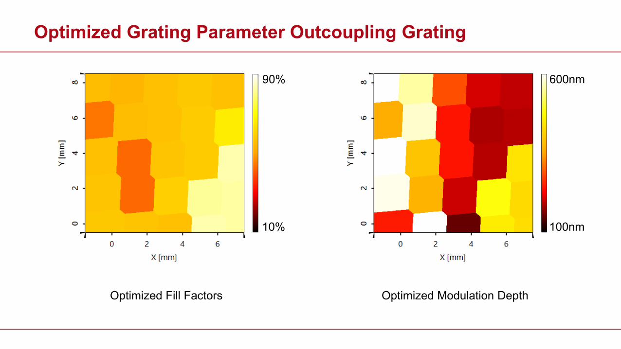
Optimized Fill Factors
Optimized Grating Parameter Outcoupling Grating
Optimized Modulation Depth
10%
90%
100nm
600nm
Page 62
Grating Design for FOV Angle (5°, 3°)
Merit Function ValueFOV Angle 𝛼𝛼 = 5°; 𝛽𝛽 = 3°
Uniformity Error 0.61 %
Page 63
Optimized Fill Factors
Optimized Grating Parameter EPE Grating
Optimized Modulation Depth
10%
90%
100nm
600nm
Page 64
Optimized Fill Factors
Optimized Grating Parameter Outcoupling Grating
Optimized Modulation Depth
10%
90%
100nm
600nm
Page 65
Grating Design for FOV Angle (6°, -2.5°)
Merit Function ValueFOV Angle 𝛼𝛼 = 6°; 𝛽𝛽 = −2.5°
Uniformity Error 1.32 %
Page 66
Optimized Fill Factors
Optimized Grating Parameter EPE Grating
Optimized Modulation Depth
10%
90%
100nm
600nm
Page 67
Optimized Fill Factors
Optimized Grating Parameter Outcoupling Grating
Optimized Modulation Depth
10%
90%
100nm
600nm
Page 68
Grating Design for FOV Angle (-6°, -3°)
Merit Function ValueFOV Angle 𝛼𝛼 = −6°; 𝛽𝛽 = −3°
Uniformity Error 1.14 %
Page 69
Optimized Fill Factors
Optimized Grating Parameter EPE Grating
Optimized Modulation Depth
10%
90%
100nm
600nm
Page 70
Optimized Fill Factors
Optimized Grating Parameter Outcoupling Grating
Optimized Modulation Depth
10%
90%
100nm
600nm
Page 71
Grating Design for FOV Angle (-7°, 2°)
Merit Function ValueFOV Angle 𝛼𝛼 = −7°; 𝛽𝛽 = 2°
Uniformity Error 0.72 %
Page 72
Optimized Fill Factors
Optimized Grating Parameter EPE Grating
Optimized Modulation Depth
10%
90%
100nm
600nm
Page 73
Optimized Fill Factors
Optimized Grating Parameter Outcoupling Grating
Optimized Modulation Depth
10%
90%
100nm
600nm
Page 74
EPE Grating Design for Different FOV: Height
Page 75
Lightguide Modeling and Design: Grating Optimization
Strategy: • Optimize grating
parameters per FOV angle
Page 76
Lightguide Modeling and Design: Grating Optimization
Strategy: • Optimize grating
parameters per FOV angle• Combine results
Page 77
Combination of Different FOV Designs
Source: www.wikipedia.com
Voronoi Segmentation
Page 78
Combination of Different FOV Designs
Source: www.wikipedia.com
Voronoi Segmentation
Page 79
Optimized Fill Factors
Optimized Grating Parameter EPE Grating
Optimized Modulation Depth
10%
90%
100nm
600nm
Page 80
Optimized Fill Factors
Optimized Grating Parameter Outcoupling Grating
Optimized Modulation Depth
10%
90%
100nm
600nm
Page 81
Result Combination of Modes (Segmentation)
Each color indicates segments, which were optimized for one mode.
Page 82
Result Combination of Modes (Segmentation)
Page 83
Result Combination of Modes (Segmentation)
Page 84
Result Combination of Modes (Segmentation)
Page 85
Result Combination of Modes (Segmentation)
Page 86
Result Combination of Modes (Segmentation)
Page 87
Result Combination of Modes (Segmentation)
Page 88
Final Design Results Mode #1 + #2
Mode Merit Function Value
#1FOV Angle 𝛼𝛼 = 0°; 𝛽𝛽 = 0°
Uniformity Error 43.90 %
Mode Merit Function Value
#2FOV Angle 𝛼𝛼 = 5°; 𝛽𝛽 = 3°
Uniformity Error 45.61 %
Page 89
Final Design Results Mode #3 - #5
Mode Merit Function Value
#3FOV Angle 𝛼𝛼 = 6°; 𝛽𝛽 =
− 2.5°
Uniformity Error 39.08 %
Mode Merit Function Value
#4FOV Angle 𝛼𝛼 = -6°; 𝛽𝛽 = −3°
Uniformity Error 36.61 %
Mode Merit Function Value
#5FOV Angle 𝛼𝛼 = -7°; 𝛽𝛽 = 2°
Uniformity Error 38.01 %
Page 90
Result Combination of Modes (Segmentation)
Page 91
Parametric Optimization and Initial Design
Initial design, e.g. • Inverse approaches• Functional design
Parametric optimization
In suitable combination
Page 92
Lightguide Modeling and Design
Page 93
Lightguide Modeling and Design
Steady R&D to tackle the uniformity challenge.
Page 94
Telescope System
System parametersMagnification 5.5XField of view 4°
Objective groupFocal length 100 mmF/# 2.8number of lenses 4
Eyepiece groupFocal length 18.3 mmExit Pupil Diameter 3.6 mmnumber of lenses 5
intermediate image
Lens source: A_019 and C_001 in Zebase
objectivef ′
eyepiecef
objectivef ′
eyepiecef
/ # fF D′= ′
where, D ′is the diameter of the entrance pupil
FOV modes behave somehow well-sorted
Page 95
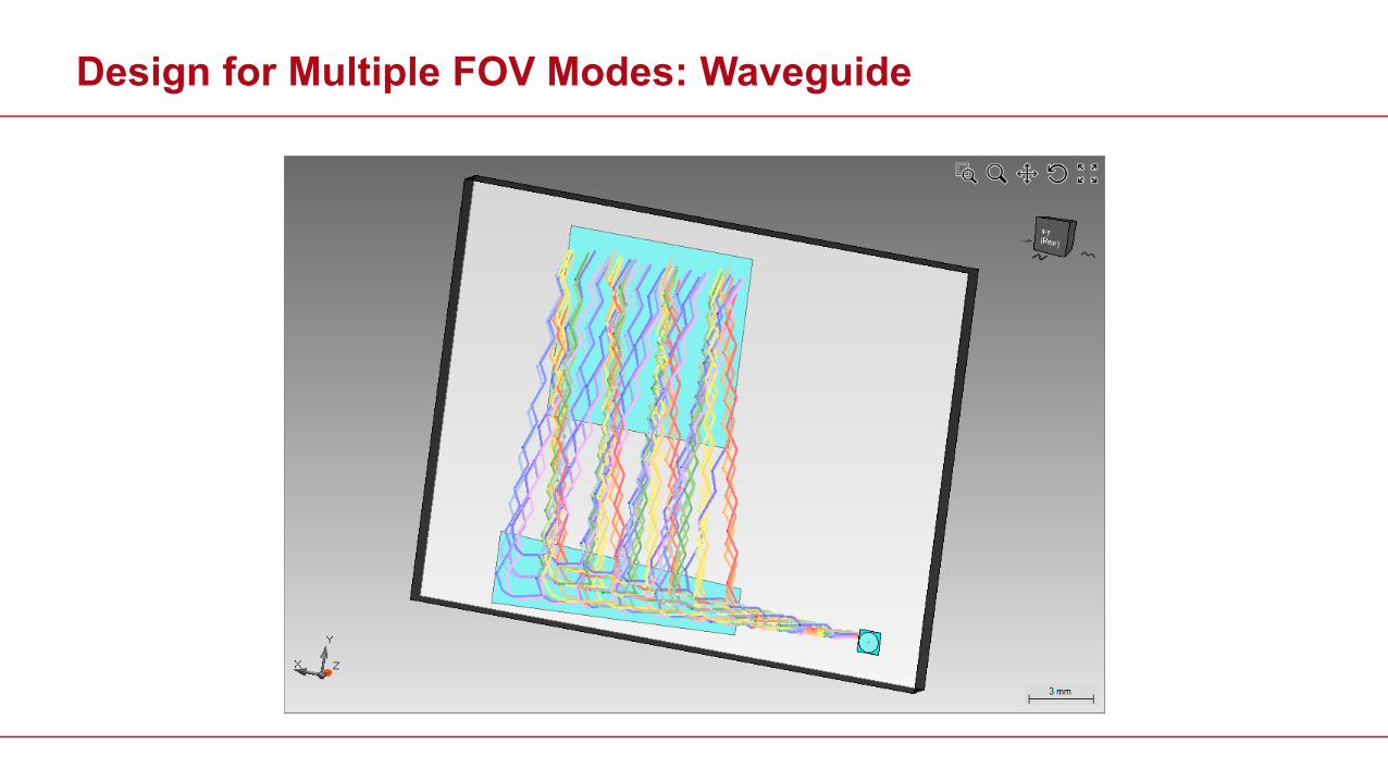
Design for Multiple FOV Modes: Waveguide
Page 96
Design for Multiple FOV Modes: Waveguide
FOV modes laterally “randomly” mixed up
Page 97
Parametric Optimization and Initial Design
Initial design, e.g. • Inverse approaches• Functional design
Parametric optimization
In suitable combination