23
Systematic Tx Eye Mask Definition John Petrilla, Avago Technologies March 2009
Systematic Tx Eye Mask Definition
John Petrilla, Avago Technologies
March 2009
March 2009 Systematic Eye Mask Definition 2
Presentation Overview
•
Problem statement & solution Comment Reference: P802.3ba D1.2, Comment 97
•
Reference Material–
Systematic Approach Proposition–
Jitter Allocation–
Extended 10GbE Link Model–
Generating Eye Masks–
Base Case
March 2009 Systematic Eye Mask Definition 3
Problem Statement Proposed Solution
•
Problem:–
The proposal for optical Tx
eye mask coordinates in Comment 427 on P802.3ba D1.1 contained an error; an intermediate value for coordinates Y1 & Y2 was reported instead of the final result. Continuing with the errant value will place an unnecessarily severe burden on an optical Tx.
–
The error in Comment 427 was noticed and reported along with the
corrected value in petrilla_01_0109. Unfortunately, although the recommendations in Comment 427 were largely accepted, this correction reported/proposed in petrilla_01_0109 was not implemented.
•
Solution:–
Adopt the remedy proposed in Comment 97 on D1.2. This is consistent with the correction to Comment 427 proposed in petrilla_01_0109.
–
In Table 86-8 change Tx
eye mask coordinates Y1 & Y2 from 0.17 to 0.33.
March 2009 Systematic Eye Mask Definition 4
TP2 Eye Mask Problem
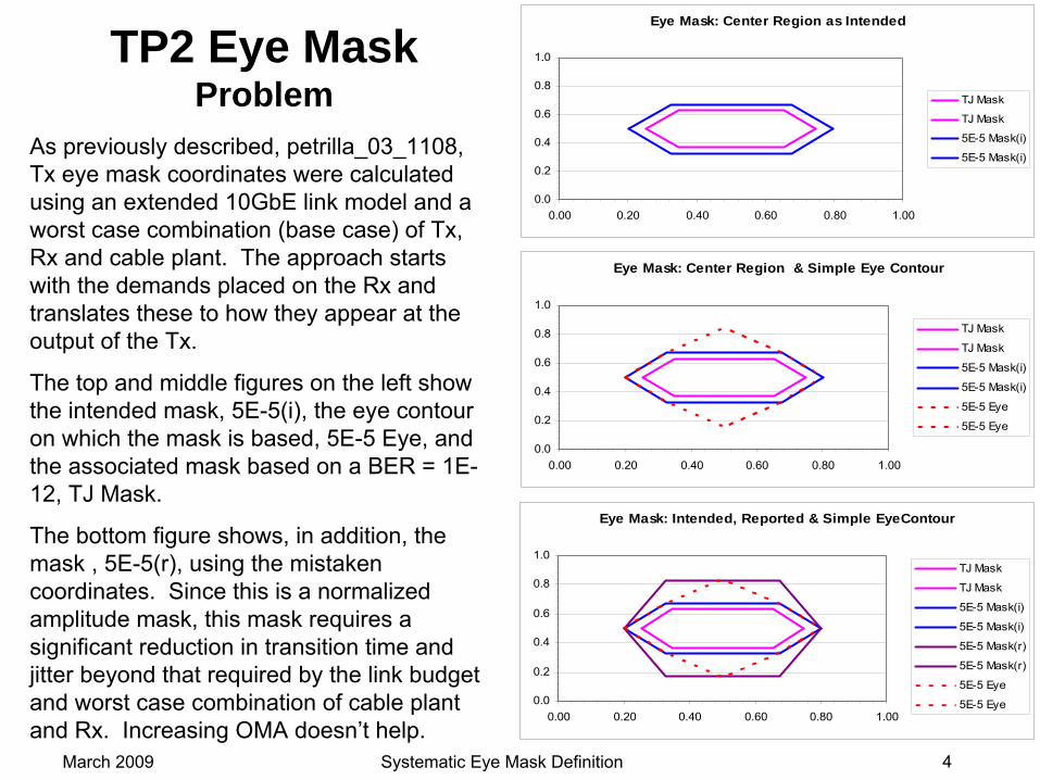
As previously described, petrilla_03_1108, Tx
eye mask coordinates were calculated using an extended 10GbE link model and a worst case combination (base case) of Tx, Rx and cable plant. The approach starts with the demands placed on the Rx and translates these to how they appear at the output of the Tx.
The top and middle figures on the left show the intended mask, 5E-5(i), the eye contour on which the mask is based, 5E-5 Eye, and the associated mask based on a BER = 1E-
12, TJ Mask.
The bottom figure shows, in addition, the mask , 5E-5(r), using the mistaken coordinates. Since this is a normalized amplitude mask, this mask requires a significant reduction in transition time and jitter beyond that required by the link budget and worst case combination of cable plant and Rx. Increasing OMA doesn’t help.
Eye Mask: Center Region as Intended
0.0
0.2
0.4
0.6
0.8
1.0
0.00 0.20 0.40 0.60 0.80 1.00
TJ Mask
TJ Mask
5E-5 Mask(i)
5E-5 Mask(i)
Eye Mask: Center Region & Simple Eye Contour
0.0
0.2
0.4
0.6
0.8
1.0
0.00 0.20 0.40 0.60 0.80 1.00
TJ Mask
TJ Mask
5E-5 Mask(i)
5E-5 Mask(i)
5E-5 Eye
5E-5 Eye
Eye Mask: Intended, Reported & Simple EyeContour
0.0
0.2
0.4
0.6
0.8
1.0
0.00 0.20 0.40 0.60 0.80 1.00
TJ Mask
TJ Mask
5E-5 Mask(i)
5E-5 Mask(i)
5E-5 Mask(r)
5E-5 Mask(r)
5E-5 Eye
5E-5 Eye
March 2009 Systematic Eye Mask Definition 5
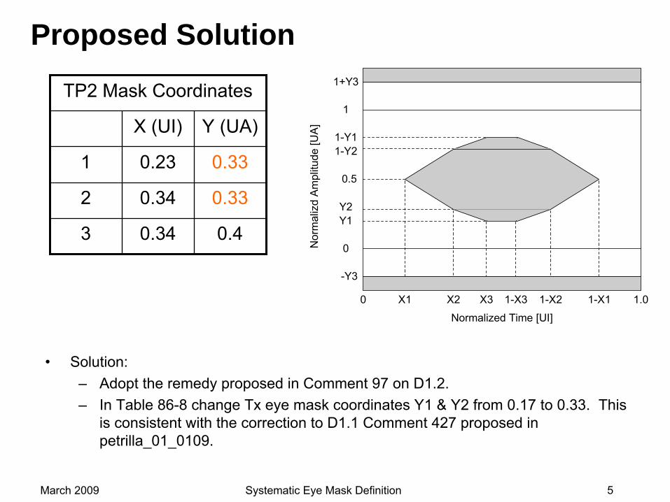
Proposed Solution
•
Solution:–
Adopt the remedy proposed in Comment 97 on D1.2.–
In Table 86-8 change Tx
eye mask coordinates Y1 & Y2 from 0.17 to 0.33. This is consistent with the correction to D1.1 Comment 427 proposed in petrilla_01_0109.
Nor
mal
izd
Am
plitu
de [U
A]
1-Y2
Y2
0.5
1-Y1
Y1
1+Y3
-Y3
Normalized Time [UI]
0 X1 X2 1-X2 1-X1 1.0X3 1-X3
1
0
TP2 Mask Coordinates
X (UI) Y (UA)
1 0.23 0.33
2 0.34 0.33
3 0.34 0.4
March 2009 Systematic Eye Mask Definition 6
Systematic Approach Proposition Conclusions, Clause 86 Comments Summary
•
It has been shown, petrilla_02_1108 and petrilla_03_1108, that a
link model can be used to determine jitter at interfaces of interest as well as define Rx-requirement-
based Tx
eye masks. Further, jitter and eye masks can be defined in terms of TJ, J2, J9 or 5E-5 hit ratios in a consistent and balanced manner. Finally, stressed Rx sensitivity conditions, J and VECP can be determined.
•
Comment 416: See page 13. SRS = -5.4 dBm, VECP = 2.0 dB, J (J2) = 0.35 UI. •
Comment 418: See pages 7 & 11. TP4 X1 = 0.26 UI.•
Comment 425: See pages 11 & 12. Here there’s an update to the remedy proposed in 425: TP1 X1 = 0.10 UI & TP2 X2 = 0.27 UI.
•
Comment 427: See page 9 & 10. Here there’s an update to the remedy proposed in 427. For a 5E-5 hit ratio, X1 = 0.20 UI, X2 = X3 = 0.33 UI & Y1 = Y2 = 0.33 UA.
Copy of page 3 from petrilla_01_0109
March 2009 Systematic Eye Mask Definition 7
Reference Material
•
Systematic Approach Proposition•
Jitter Allocation: Base Case (updated)
• Extended 10GbE Link Model•
Generating Eye Masks (updated)
• Base Case Definition (updated)
March 2009 Systematic Eye Mask Definition 8
Systematic Approach Proposition
•
Jitter Allocation: An extended 10GbE link model can be used to convert noise penalties into jitter at each interface of interest. See petrilla_02_1108. This reconciles jitter allocations with power penalties and provides a consistent allocation approach that enables balancing the burden at the various interfaces. It also permits a more appropriate determination of the jitter used for stressed
receiver test set-ups. •
Eye Mask: An extended 10GbE link model can be used to define Tx
eye masks that ensure better than required signal characteristics at Rx inputs while minimizing unneeded burdens. See petrilla_03_1108. By only requiring what
is needed by the downstream receiver, neither the Tx
nor the Rx face an unnecessary or disproportionate burden.
•
Jitter, being one-dimensional, permits easier de-embedding of test equipment artifacts than the two-dimensional nature of eye displays. Consequently, while jitter specifications can be written without including consideration of
test artifacts, it appears advantageous to define mask coordinates with a minimum performance level reference test system.
•
Herein, for eye diagrams, as an example of a minimum performance
reference test system, a sampling scope was assumed with a timing uncertainty of 0.2 ps
RMS, electrical sensitivity and BW that provide no significant impairment and an optical sensitivity of -14.5 dBm and BW of 7.5GHz. A BW requirement for an eye mask tests is already common practice.
March 2009 Systematic Eye Mask Definition 9
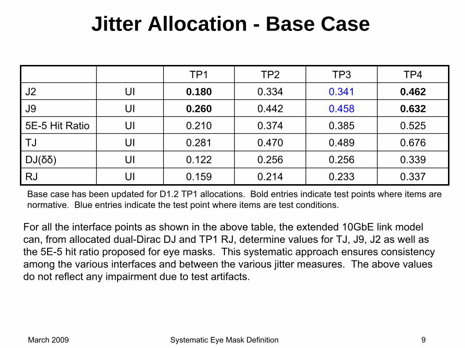
Jitter Allocation - Base Case
TP1 TP2 TP3 TP4J2 UI 0.180 0.334 0.341 0.462J9 UI 0.260 0.442 0.458 0.6325E-5 Hit Ratio UI 0.210 0.374 0.385 0.525TJ UI 0.281 0.470 0.489 0.676DJ(δδ) UI 0.122 0.256 0.256 0.339RJ UI 0.159 0.214 0.233 0.337Base case has been updated for D1.2 TP1 allocations. Bold entries indicate test points where items are normative. Blue entries indicate the test point where items are test conditions.
For all the interface points as shown in the above table, the extended 10GbE link model can, from allocated dual-Dirac DJ and TP1 RJ, determine values for TJ, J9, J2 as well as the 5E-5 hit ratio proposed for eye masks. This systematic approach ensures consistency among the various interfaces and between the various jitter measures. The above values do not reflect any impairment due to test artifacts.
March 2009 Systematic Eye Mask Definition 10
10G Ethernet Link Models
The link model (hereafter 10GbE) used in development of 10G Ethernet (10GEPBud3_1_16a.xls) is available at the IEEE P802.3ae 10Gb/s Ethernet Task Force Serial PMD documents website http://www.ieee802.org/3/ae/public/adhoc/serial_pmd/documents/
.
One of several available discussions, The 10G Ethernet Link Model, is available at the IEEE HSSG website http://www.ieee802.org/3/hssg/public/nov06/dawe_01_1106.pdf . This presentation includes an extensive list of references.
Extensions for the 10GbE model that include effects of source RJ
at TP1 and DJ added between TP3.5 and TP4, calculates the open eye width at
TP4, providing a means to harmonized power penalties and jitter are described in petrilla_02_1108. Using the extended model to generate Tx
eye masks is described in petrilla_03_1108.
March 2009 Systematic Eye Mask Definition 11
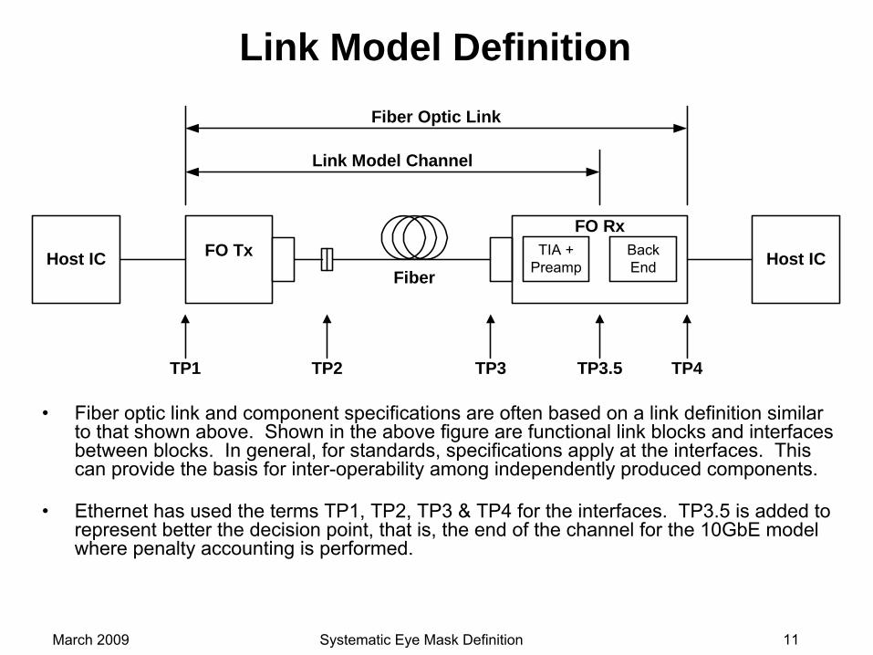
Link Model Definition
•
Fiber optic link and component specifications are often based on
a link definition similar to that shown above. Shown in the above figure are functional link blocks and interfaces between blocks. In general, for standards, specifications apply
at the interfaces. This can provide the basis for inter-operability among independently produced components.
•
Ethernet has used the terms TP1, TP2, TP3 & TP4 for the interfaces. TP3.5 is added to represent better the decision point, that is, the end of the channel for the 10GbE model where penalty accounting is performed.
Host IC Host ICFO TxFiber
TIA +Preamp
BackEnd
FO Rx
Fiber Optic Link
Link Model Channel
TP1 TP2 TP3 TP4TP3.5
March 2009 Systematic Eye Mask Definition 12
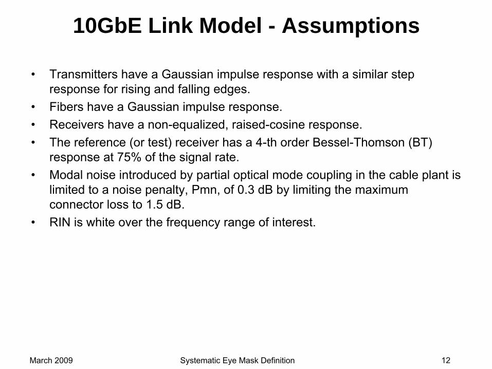
10GbE Link Model - Assumptions
•
Transmitters have a Gaussian impulse response with a similar step response for rising and falling edges.
•
Fibers have a Gaussian impulse response.•
Receivers have a non-equalized, raised-cosine response.•
The reference (or test) receiver has a 4-th order Bessel-Thomson (BT) response at 75% of the signal rate.
•
Modal noise introduced by partial optical mode coupling in the cable plant is limited to a noise penalty, Pmn, of 0.3 dB by limiting the maximum connector loss to 1.5 dB.
•
RIN is white over the frequency range of interest.
March 2009 Systematic Eye Mask Definition 13
Additional Assumptions for Extension
•
Jitter at the interfaces can be partitioned into random, RJ, and
deterministic, DJ, components using Dual Dirac jitter methods. For the rest of
this presentation, DJ refers to Dual Dirac DJ.
•
The signal (amplitude) noise in the optical link is transformed into random (Gaussian) jitter by the non-vertical edges of the signal transitions.
•
Input referred receiver noise is Gaussian.•
At the corners of the eye opening, the vertical closure due to the power penalties and signal loss coincides with the horizontal closure due to jitter.
•
Receiver sensitivity includes the minimum output swing requirements for the receiver.
March 2009 Systematic Eye Mask Definition 14
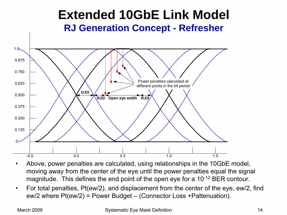
Extended 10GbE Link Model RJ Generation Concept - Refresher
•
Above, power penalties are calculated, using relationships in the 10GbE model, moving away from the center of the eye until the power penalties
equal the signal magnitude. This defines the end point of the open eye for a 10-12
BER contour.•
For total penalties, Pt(ew/2), and displacement from the center of the eye, ew/2, find ew/2 where Pt(ew/2) = Power Budget –
(Connector Loss +Pattenuation).
0.0 0.5 1.0
0
0.125
0.250
0.375
0.500
0.625
0.750
0.875
1.0
Open eye width
Power penalties calculated atdifferent points in the bit period
1.5-0.5
DJ/2RJ/2 RJ/2
March 2009 Systematic Eye Mask Definition 15
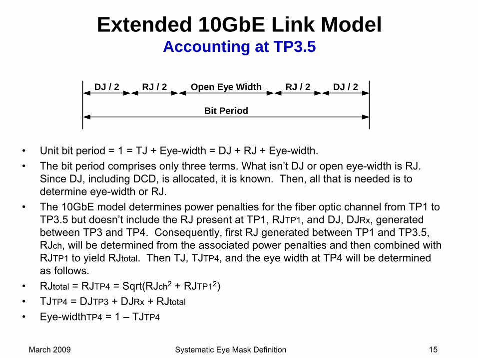
Extended 10GbE Link Model Accounting at TP3.5
DJ / 2 DJ / 2RJ / 2RJ / 2 Open Eye Width
Bit Period
•
Unit bit period = 1 = TJ + Eye-width = DJ + RJ + Eye-width.•
The bit period comprises only three terms. What isn’t DJ or open eye-width is RJ. Since DJ, including DCD, is allocated, it is known. Then, all that is needed is to determine eye-width or RJ.
•
The 10GbE model determines power penalties for the fiber optic channel from TP1 to TP3.5 but doesn’t include the RJ present at TP1, RJTP1, and DJ, DJRx, generated between TP3 and TP4. Consequently, first RJ generated between TP1 and TP3.5, RJch, will be determined from the associated power penalties and then combined with RJTP1
to yield RJtotal. Then TJ, TJTP4, and the eye width at TP4 will be determined as follows.
•
RJtotal
= RJTP4
= Sqrt(RJch2
+ RJTP12)•
TJTP4
= DJTP3
+ DJRx
+ RJtotal
•
Eye-widthTP4
= 1 –
TJTP4
March 2009 Systematic Eye Mask Definition 16
Tx Eye Mask Generation - Overview
•
The following pages present a method of generating eye masks based on BER contours, i.e.
-
show 10^-12 BER contours -
show progression of required contour/eye from TP3.5 to TP2
-
show translation of contour into mask
-
show translation of contours and masks from a BER = 1E-12 basis to a 5E-5 hit ratio basis.
Contour/Mask Generation Approach and/or Assumptions:
-
For contours each bit is at worst case dual-Dirac deterministic jitter, DJ(δδ).
-
Receiver requirements are based on unstressed receiver sensitivity.
-
The Reference/Test Rx only contributes RJ and ISI generated DJ.
-
In test set-ups, observed optical-noise and random jitter beyond that due to TP1 jitter, RIN of the device under test, test receiver sensitivity or test equipment timing uncertainty, is due to modal noise associated with incomplete modal coupling at the optical connectors. -
Although the Reference/Test Rx assumes a 4th-Order BT response, no adjustment is made to the receiver time constant parameter in the spreadsheet.
March 2009 Systematic Eye Mask Definition 17
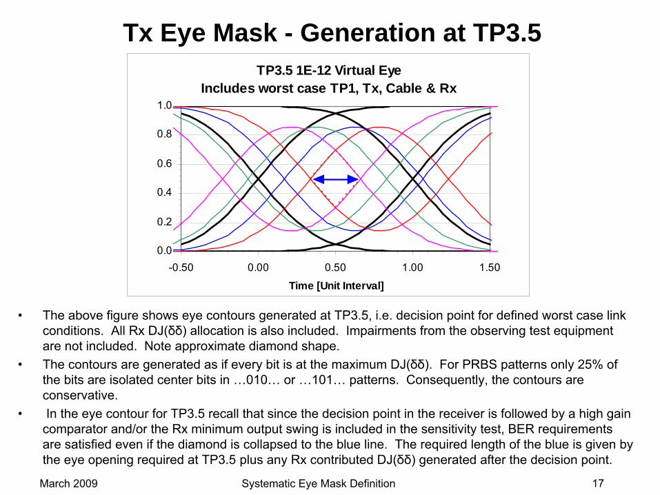
Tx Eye Mask - Generation at TP3.5
•
The above figure shows eye contours generated at TP3.5, i.e. decision point for defined worst case link conditions. All Rx DJ(δδ)
allocation is also included. Impairments from the observing test equipment are not included. Note approximate diamond shape.
•
The contours are generated as if every bit is at the maximum DJ(δδ). For PRBS patterns only 25% of the bits are isolated center bits in …010…
or …101…
patterns. Consequently, the contours are conservative.
•
In the eye contour for TP3.5 recall that since the decision point in the receiver is followed by a high gain comparator and/or the Rx minimum output swing is included in the
sensitivity test, BER requirements are satisfied even if the diamond is collapsed to the blue line.
The required length of the blue is given by the eye opening required at TP3.5 plus any Rx contributed DJ(δδ) generated after the decision point.
TP3.5 1E-12 Virtual EyeIncludes worst case TP1, Tx, Cable & Rx
0.0
0.2
0.4
0.6
0.8
1.0
-0.50 0.00 0.50 1.00 1.50
Time [Unit Interval]
March 2009 Systematic Eye Mask Definition 18
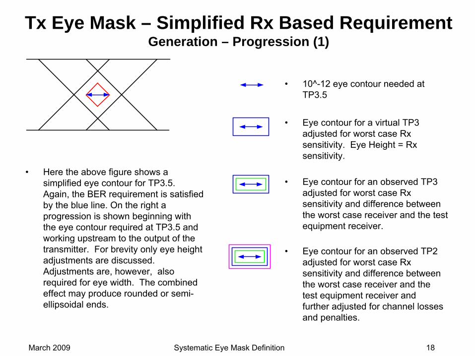
Tx Eye Mask – Simplified Rx Based Requirement Generation – Progression (1)
•
Here the above figure shows a simplified eye contour for TP3.5. Again, the BER requirement is satisfied by the blue line. On the right a progression is shown beginning with the eye contour required at TP3.5 and working upstream to the output of the transmitter. For brevity only eye height adjustments are discussed. Adjustments are, however, also required for eye width. The combined effect may produce rounded or semi-
ellipsoidal ends.
•
10^-12 eye contour needed at TP3.5
•
Eye contour for a virtual TP3 adjusted for worst case Rx sensitivity. Eye Height = Rx sensitivity.
•
Eye contour for an observed TP3
adjusted for worst case Rx sensitivity and difference between the worst case receiver and the test equipment receiver.
•
Eye contour for an observed TP2
adjusted for worst case Rx sensitivity and difference between the worst case receiver and the test equipment receiver and further adjusted for channel losses and penalties.
March 2009 Systematic Eye Mask Definition 19
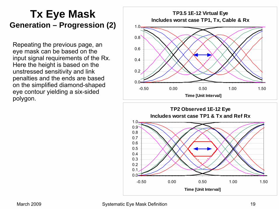
Tx Eye Mask Generation – Progression (2)
TP3.5 1E-12 Virtual EyeIncludes worst case TP1, Tx, Cable & Rx
0.0
0.2
0.4
0.6
0.8
1.0
-0.50 0.00 0.50 1.00 1.50
Time [Unit Interval]
TP2 Observed 1E-12 EyeIncludes worst case TP1 & Tx and Ref Rx
0.00.10.20.30.40.50.60.70.80.91.0
-0.50 0.00 0.50 1.00 1.50
Time [Unit Interval]
Repeating the previous page, an eye mask can be based on the input signal requirements of the Rx. Here the height is based on the unstressed sensitivity and link penalties and the ends are based on the simplified diamond-shaped eye contour yielding a six-sided polygon.
March 2009 Systematic Eye Mask Definition 20
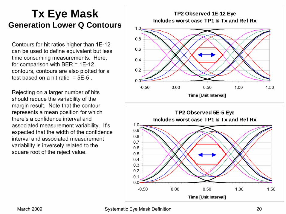
TP2 Observed 1E-12 EyeIncludes worst case TP1 & Tx and Ref Rx
0.0
0.2
0.4
0.6
0.8
1.0
-0.50 0.00 0.50 1.00 1.50
Time [Unit Interval]
Tx Eye Mask Generation Lower Q Contours
TP2 Observed 5E-5 EyeIncludes worst case TP1 & Tx and Ref Rx
0.00.10.20.30.40.50.60.70.80.91.0
-0.50 0.00 0.50 1.00 1.50
Time [Unit Interval]
Contours for hit ratios higher than 1E-12 can be used to define equivalent but less time consuming measurements. Here, for comparison with BER = 1E-12 contours, contours are also plotted for a test based on a hit ratio = 5E-5 .
Rejecting on a larger number of hits should reduce the variability of the margin result. Note that the contour represents a mean position for which there’s a confidence interval and associated measurement variability. It’s expected that the width of the confidence interval and associated measurement variability is inversely related to the square root of the reject value.
March 2009 Systematic Eye Mask Definition 21
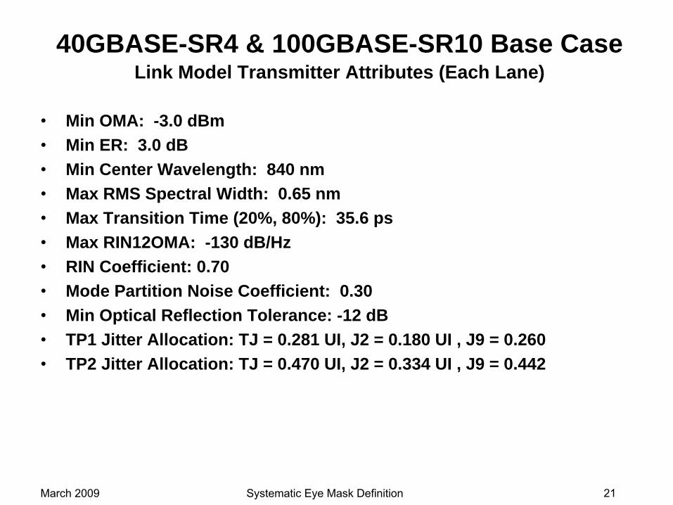
40GBASE-SR4 & 100GBASE-SR10 Base Case Link Model Transmitter Attributes (Each Lane)
•
Min OMA: -3.0 dBm•
Min ER: 3.0 dB•
Min Center Wavelength: 840 nm•
Max RMS Spectral Width: 0.65 nm•
Max Transition Time (20%, 80%): 35.6 ps•
Max RIN12OMA: -130 dB/Hz•
RIN Coefficient: 0.70•
Mode Partition Noise Coefficient: 0.30•
Min Optical Reflection Tolerance: -12 dB•
TP1 Jitter Allocation: TJ = 0.281 UI, J2 = 0.180 UI , J9 = 0.260•
TP2 Jitter Allocation: TJ = 0.470 UI, J2 = 0.334 UI , J9 = 0.442
March 2009 Systematic Eye Mask Definition 22
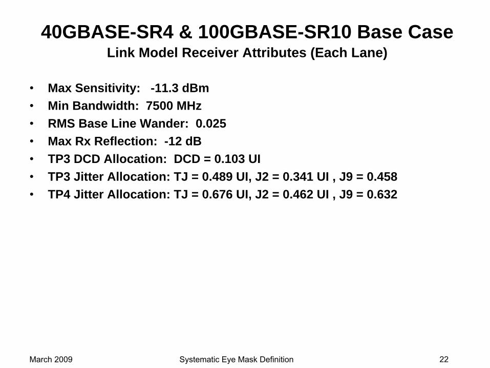
40GBASE-SR4 & 100GBASE-SR10 Base Case Link Model Receiver Attributes (Each Lane)
•
Max Sensitivity: -11.3 dBm•
Min Bandwidth: 7500 MHz•
RMS Base Line Wander: 0.025•
Max Rx Reflection: -12 dB•
TP3 DCD Allocation: DCD = 0.103 UI•
TP3 Jitter Allocation: TJ = 0.489 UI, J2 = 0.341 UI , J9 = 0.458•
TP4 Jitter Allocation: TJ = 0.676 UI, J2 = 0.462 UI , J9 = 0.632
March 2009 Systematic Eye Mask Definition 23
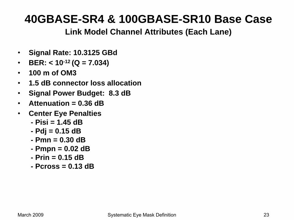
40GBASE-SR4 & 100GBASE-SR10 Base Case Link Model Channel Attributes (Each Lane)
•
Signal Rate: 10.3125 GBd •
BER: < 10-12 (Q = 7.034)•
100 m of OM3•
1.5 dB connector loss allocation•
Signal Power Budget: 8.3 dB•
Attenuation = 0.36 dB•
Center Eye Penalties - Pisi = 1.45 dB - Pdj = 0.15 dB - Pmn = 0.30 dB - Pmpn = 0.02 dB - Prin = 0.15 dB - Pcross = 0.13 dB


