Systems Analysis of Physical Absorption of CO2 in Ionic Liquids forPre-Combustion Carbon CaptureHaibo Zhai* and Edward S. Rubin
Department of Engineering and Public Policy, Carnegie Mellon University, Pittsburgh, Pennsylvania 15213, United States
*S Supporting Information
ABSTRACT: This study develops an integrated technical and economic modeling frameworkto investigate the feasibility of ionic liquids (ILs) for precombustion carbon capture. The IL 1-hexyl-3-methylimidazolium bis(trifluoromethylsulfonyl)imide is modeled as a potential physicalsolvent for CO2 capture at integrated gasification combined cycle (IGCC) power plants. Theanalysis reveals that the energy penalty of the IL-based capture system comes mainly from theprocess and product streams compression and solvent pumping, while the major capital costcomponents are the compressors and absorbers. On the basis of the plant-level analysis, thecost of CO2 avoided by the IL-based capture and storage system is estimated to be $63 pertonne of CO2. Technical and economic comparisons between IL- and Selexol-based capturesystems at the plant level show that an IL-based system could be a feasible option for CO2 capture. Improving the CO2 solubilityof ILs can simplify the capture process configuration and lower the process energy and cost penalties to further enhance theviability of this technology.
■ INTRODUCTION
Ionic liquids (ILs) are under active development as emergingtechnologies for carbon dioxide (CO2) capture because of theirfavorable properties, such as relative nonvolatility, high CO2solubility and selectivity, and endless tenability.1−3 ILs also canbe used for CO2 capture without water dilution, which reducesthe parasitic load of capture systems.1 However, their highviscosity poses a challenge for large-scale applications.Research on ILs has been emphasized on laboratory
experiments, molecular and phase equilibrium simulations,and materials synthesis.2,4−7 More novel ILs with high capacityand low viscosity are being synthesized, especially forpostcombustion CO2 capture.
8−10 While research activities onILs focus mainly on the application to postcombustion CO2capture,11−14 there have been relatively few studies of ILs forprecombustion CO2 capture at integrated gasification com-bined cycle (IGCC) power plants. The shifted gas streamconsists mainly of CO2 (∼38%) and hydrogen (H2) (∼56%),with CO2 partial pressures that can be several tens of bars atIGCC plants. So, ILs also appear attractive as a potentialphysical solvent for precombustion CO2 capture.
15 Shiflett andYokozeki measured and predicted the solubility of CO2 in 1-hexyl-3-methylimidazolium bis(trifluoromethylsulfonyl)imide([hmim][Tf2N]).
16 Recent computational studies demonstra-ted the technical feasibility of absorption processes using[hmim][Tf2N] and two TEGO ILs as a physical solvent forcapturing CO2 at an IGCC plant, but lacked cost evalua-tion.17,18 Garcia-Gutierrez et al. also demonstrated thefeasibility of using ILs as a physical solvent for capturing CO2from biogas streams.19
A variety of thermodynamic models have been developed topredict the phase behavior of CO2 and other gases in variousILs, such as classical cubic equations, activity coefficient and
group contribution methods, and quantum chemistry calcu-lations,3,20−23 and data mining algorithms.24,25 However, muchless attention has been paid to the simulation and design of IL-based capture systems,4 and the cost of IL-based capturesystems has rarely been evaluated. The major objectives of thisstudy, therefore, are to evaluate the techno-economic feasibilityof ILs for precombustion CO2 capture at IGCC plants and toexplore the measures needed to improve the viability of thistechnology.To achieve these objectives, this study develops an integrated
technical and economic modeling framework for assessingprecombustion capture processes, with a focus on theseparation of CO2 and H2. Given the technical feasibility forCO2 capture,
16,17 the ionic liquid [hmim][Tf2N] is selected forthe assessment and serves as a proxy solvent for “backengineering” to explore desired IL properties and theirpotential role in improving overall process viability. Quantifyingpotential benefits from improved solvent properties is helpfulto guide the development of new materials for carbon capture.
■ MATERIALS AND METHODS
This section presents details of the performance and costmodels developed to analyze the IL-based option for IGCCplants. Subsequent sections present plant-level results andcomparisons with current commercial alternatives.
Performance Modeling of CO2 Capture System. Theperformance modeling framework for precombustion CO2capture mainly includes the phase equilibrium model, plus
Received: January 22, 2018Revised: March 25, 2018Accepted: March 28, 2018Published: March 28, 2018
the mass and energy balance models for an IL-based capturesystem.Physical Properties of Solvent and Gases. Solvent proper-
ties correlate with temperature and/or pressure. Basha et al.developed correlations for density, surface tension, viscosity,and heat capacity for [hmim][Tf2N] based on data from theliterature.17 The vapor pressure of [hmim][Tf2N] is extremelylow and negligible.17
The correlations of density, viscosity, and heat capacity withtemperature and pressure are formulated for CO2 and H2 basedon data available from the National Institute of Standards andTechnology’s properties database for fluid systems.26 For CO2,the gas-phase diffusivity is predicted using the correlationequation developed by Fuller et al.,27 whereas the liquid-phasediffusion coefficient is estimated as a function of the solventviscosity.28 Solvent and gas properties are summarized inTables S1, S2, and S3 of the Supporting Information (SI).Phase Equilibrium based on Equation of State. The
generic Redlich−Kwong Equation of State (RK EOS), relatingtemperature, pressure, and volume of gases, can be applied topredict the phase behavior of gases in solvents, such as ILs.16
The modified RK EOS is expressed as follows:16,29
=−
−+
PRT
V ba T
V V b( )
( ) (1)
For N-component mixtures, mixing rules are applied toestimate the parameters (a, b) in the RK EOS as16,29
∑= −=
a a a f T k x x( )(1 )i j
i j ij ij i j, 1
N
(2)
α=aR T
PT0.427480 ( )i
i
ii
2c,2
c, (3)
∑α
β
β β
=− ≤
+ − − >=
≤⎧⎨⎪⎪
⎩⎪⎪
TT T T T T T
T T T T
( )( / / ) , / 1
[exp(2(1 / )) 1], / 1i k
kk
0
3
c c c
0 1 c c
(4)
τ= +f T
T( ) 1i j
ij, (5)
=+
+k
l l x x
l x x
( )
lijij ji i j
ji i ij j (6)
∑= + − −=
b b b k m x x12
( )(1 )(1 )i j
N
i j ij ij i j, 1 (7)
=bRT
P0.08664i
i
i
c,
c, (8)
where Tc,i is the critical temperature of the ith species (°K), Pc,iis the critical pressure of the ith species (kPa), R is the universalgas constant, and xi is the mole fraction of the ith species. Thereare four binary-interaction parameters for each pair ofcomponents in the system: lij, lji, mij, and τij. However, two orthree parameters are sufficient for most equilibrium applica-tions.29 The fugacity coefficient of the ith component derivedfrom the RK EOS is described as follows:29
Φ =−
+ −
−+
+
−
++
⎛⎝⎜
⎞⎠⎟
⎛⎝⎜
⎞⎠⎟
RTP V b
bV b
aRTb V b
aRTb
aa
bb
VV b
ln ln( )
1( )
1 ln
i i
i i
(9)
in which,
∑ = − −−
+−
=⎪ ⎪
⎪ ⎪⎧⎨⎩
⎫⎬⎭
a a a f x kl l l l x x
l x l xa2 1
( )
( )ij
N
i j ij j ijij ji ij ji i j
ji i ij j12
∑ = + − − −−
+−
=
⎪
⎪
⎪
⎪
⎧⎨⎩
⎫⎬⎭
b b b m x kl l l l x x
l x l xb( )(1 ) 1
( )
( )ij
N
i j ij j ijij ji ij ji i j
ji i ij j12
For a component (i), the K-value of vapor−liquid equilibrium(VLE) is calculated as the ratio of liquid versus vapor fugacitycoefficients (Φi
L, ΦiV) from eq 9:
=ΦΦ
Kii
i
L
V(10)
The critical component parameters and constants in the VLEmodel are summarized in Table S4 of the SI. The binary-interaction parameters can be estimated by correlating theexperimental solubility data with the RK EOS. The binaryparameters of interactions between CO2 and [hmim][Tf2N]and between CO2 and H2 come from the estimates by Shiflettand Yokozeki.16,29 The binary interaction parameters for H2and [hmim][Tf2N] are determined by fitting the solubility dataavailable from the literature.30 The binary-interaction parame-ters used for each pair are summarized in Table S5 of the SI.The phase equilibrium model of CO2 and H2 in [hmim][Tf2N]was incorporated in the absorption and stripping processsimulation.
Multistage Equilibrium Process Model for Gas Absorption.Gas absorption using [hmim][Tf2N] for CO2 capture is treatedas a steady-state vapor−liquid process that consists of multipleequilibrium stages. For any stage in a countercurrent cascade,vapor and liquid streams leave in phase equilibrium. Then, amultistage equilibrium model is developed to delineate theabsorption process, including the mass balance (M), phaseequilibrium (E), summation (S), and enthalpy balance (H) ateach stage:Mass balance for each component at stage (j):
− + − =− − + +L x L x V y V y 0j i j j i j j i j j i j1 , 1 , 1 , 1 , (11)
Equilibrium for each component at stage (j):
= ×y K xi j i j i j, , , (12)
The phase equilibrium is predicted using the RK EOS-basedmodel defined in eq 10.Summation based on mole fractions at stage (j):
∑ ∑= =x y 1i j i j, , (13)
Enthalpy balance at stage (j):
− + − − =− − + +L H L H V H V H Q 0j j j j j j j j1 L, 1 L, 1 V, 1 V, (14)
in which HL is the enthalpy of liquid flow (kJ/kmole); HV is theenthalpy of gas flow (kJ/kmole); L is the solvent molar flowrate (kmol/h); K is the phase equilibrium constant (ratio); Q isthe cooling duty (kJ/h); V is the gas molar flow rate (kmol/h);x is the mole fraction in liquid phase; and y is the mole fractionin gas phase. An inside-out (I/O) algorithm is applied to solve
the coupled MESH equations, which employs two sets ofthermodynamic property models: a simple, approximate,empirical set used frequently to converge inner-loop calcu-lations, and a rigorous set used less often in the outer loop.31,32
The pressure drop across an absorber is estimated as theproduct of pressure drop rate and absorber height. Thegeneralized SherwooLeva/Eckert correlation is used to estimatethe pressure drop rate.33,34 The absorber height is estimatedbased on the overall gas-phase mass transfer coefficient ofphysical absorption, using mass transfer correlations developedby Onda et al. for randomly packed vessels.35 Details of thepressure drop estimation are given in Section S3 of the SI.Flashing for Solvent Regeneration. For solvent regener-
ation, the CO2-rich solvent stream exiting the absorber with amuch high pressure can enter multiple flash drums with lowerpressures, which is similar to the design adopted for Selexol-based CO2 capture.36 The solvent is regenerated andrecirculated to the absorber, while the CO2 is released fromthe solvent in a series of flash drums and further compressed fortransport to a storage site. The calculation of TP-flash based onthe phase equilibrium model discussed above is performed toassess the stripping process.Key Power Equipment. There is no thermal energy required
for the IL-based capture process. However, electric power isrequired for process and CO2 product streams compression andsolvent pumping. In the pressure swing for solvent regener-ation, some energy from high-pressure solvent streams can berecovered by hydraulic power turbines.37 Equipment power usecalculations are detailed in Section S4 of the SI.Engineering-Economic Analysis of CO2 Capture
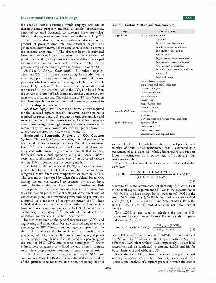
System. This study adopts the costing method presented inthe Electric Power Research Institute’s Technical AssessmentGuide.38,39 The performance models discussed above areintegrated with engineering-economic models that estimatethe capital cost, annual operating and maintenance (O&M)costs, and total annual levelized cost of an IL-based capturesystem. Table 1 summarizes the costing method.The total capital requirement (TCR) includes the direct
process facilities cost (PFC) plus a number of indirect costcategories. Major direct cost components are given in Table 1.The cost model developed by Chen for a Selexol-based CO2capture system was adopted to estimate the major directcosts.37 In the model, the direct costs of absorber and flashdrums per train are estimated as a function of stream mass flowrates and process pressure if applicable, while the direct costs ofcompressor, pump, and hydraulic power turbine per train areestimated as a function of equipment power use.37 Theseindividual direct cost estimates were further updated mainlybased on more recent cost studies by the U.S. National EnergyTechnology Laboratory.40−44 Details of the direct costestimation are available in Section S5 of the SI.Indirect costs such as the general facilities cost (GFC) and
engineering and home office fees are estimated empirically as apercentage of PFC. The process contingency depends on thestatus of technology development and is estimated as apercentage of PFC, whereas the project contingency dependson the project design level and is estimated as a percentage ofthe sum of PFC, GFC, and process contingency.38 Otherindirect cost categories considered include interest charges,royalty fees, preproduction cost, and inventory capital cost.Table 1 also summarizes variable and fixed O&M cost
components. Variable O&M costs are estimated as the productof the quantity used times the unit price. Operating labor is
estimated in terms of hourly labor rate, personnel per shift, andnumber of shifts. Total maintenance cost is estimated as apercentage of total plant cost, while administrative and supportlabor is estimated as a percentage of operating plusmaintenance labor.The LCOE of an overall plant or a system is then calculated
as follows:45
= × + +× ×
+ ×LCOETCR FCF FOM VOM
(CF 8760) MWHR FC
(15)
where LCOE is the levelized cost of electricity ($/MWh); TCRis the total capital requirement ($); CF is the capacity factor(%); FCF is the fixed charge factor (fraction/yr); FOM is thefixed O&M costs ($/yr); VOM is the nonfuel variable O&Mcosts ($/yr); HR is the net heat rate (MBtu/MWh); FC is theunit fuel cost ($/MBtu); and MW is the net power output(MW).The LCOE is also used to calculate the cost of CO2
avoideda key measure of the overall cost of carbon captureand storage (CCS):45
=−
−cost of CO avoided ($/t CO )
(LCOE) (LCOE)(ER) (ER)2 2
CCS ref
ref CCS (16)
where ER is the CO2 emission rate (t/MWh). The subscripts of“CCS” and “Ref” indicate an IGCC plant with CCS and areference IGCC plant without CCS, respectively. A plant-levelassessment will be conducted to estimate LCOE and ER forboth plants with and without CCS.Some studies of CO2 capture processes also report the cost
of CO2 separation ($/t CO2). This is typically based on a“stand-alone” analysis of a capture process in which the cost of
Table 1. Costing Method and Nomenclature
category cost component
capital cost process facilities capitalabsorbershigh-pressure flash drumsmiddle-pressure flash drumslow-pressure flash drumssolvent pumpshigh-pressure stream compressorslow-pressure stream compressorsCO2 product compressorshydraulic power recovery turbinessump tanksheat exchangers
general facilities capitalengineering and home office feesproject contingencyprocess contingencyinterest chargesroyalty feespreproduction costinventory capital
variable O&M cost solvent makeupelectricityCO2 transport and storage when applicable
fixed O&M cost operating labormaintenance labormaintenance materialadministrative and support labor
energy to operate the system is assumed to be purchasedexternally. This measure of cost is given by the following:
= × + +× × m
cost of CO separationTCR FCF FOM VOM
(CF 8760)2CO2
(17)
Integrated Environmental Control Model for PowerPlant Assessments. The Integrated Environmental ControlModel (IECM) is a computer-modeling tool developed byCarnegie Mellon University for power plant assessments.44 TheIECM provides systematic estimates of the performance,emissions, and costs for a variety of fossil-fuel fired powergeneration systems with and without CCS, including IGCCsystems.36,37,40,46 To evaluate the effects of CCS deploymenton the overall plant performance and cost, the 2017 release ofIECM (Version 9.5) was employed for this study.44 The newperformance and cost models developed for IL-based CO2
capture were integrated with the IECM framework and used toconduct techno-economic assessments at both process andplant levels.
■ BASE CASE RESULTS
Here we present results for base case assumptions using currentIL properties. First we show results for the stand-alone IL-basedcapture process. Then we show results for a complete powerplant with precombustion capture. Following this, we look atpotential process improvements that can enhance the viabilityof ILs for precombustion CO2 capture applications.
Phase Equilibrium of CO2 and H2 in [hmim][Tf2N]. Thecalibrated VLE model based on the modified RK EOS canpredict the CO2 and H2 phase behavior under differenttemperatures and pressures. Figure 1(a) and (b) present thePT-x phase diagram for CO2 and H2 in a binary system,respectively. CO2 has a much larger solubility than H2. Whenthe interaction between CO2 and H2 in a tertiary system isconsidered, the EOS-based VLE model needs to be furtheradjusted by incorporating the binary interaction parameters ofCO2 and H2 to predict the simultaneous solubility of CO2 andH2 in [hmim][Tf2N]. The predicted pressure of the tertiarysystem matches well with an experimental study conducted byKumelan et al.,47 resulting in an R2 value of 0.996.
Figure 1. PT-x phase diagram for a binary system (a) CO2 in [hmim][Tf2N]; (b) H2 in [hmim][Tf2N].
Figure 2. Precombustion CO2 capture system using [hmim][Tf2N].
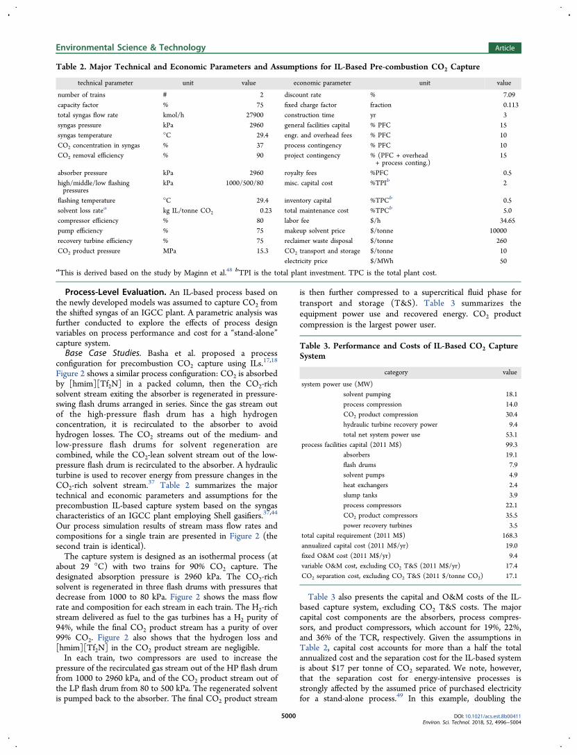
Process-Level Evaluation. An IL-based process based onthe newly developed models was assumed to capture CO2 fromthe shifted syngas of an IGCC plant. A parametric analysis wasfurther conducted to explore the effects of process designvariables on process performance and cost for a “stand-alone”capture system.Base Case Studies. Basha et al. proposed a process
configuration for precombustion CO2 capture using ILs.17,18
Figure 2 shows a similar process configuration: CO2 is absorbedby [hmim][Tf2N] in a packed column, then the CO2-richsolvent stream exiting the absorber is regenerated in pressure-swing flash drums arranged in series. Since the gas stream outof the high-pressure flash drum has a high hydrogenconcentration, it is recirculated to the absorber to avoidhydrogen losses. The CO2 streams out of the medium- andlow-pressure flash drums for solvent regeneration arecombined, while the CO2-lean solvent stream out of the low-pressure flash drum is recirculated to the absorber. A hydraulicturbine is used to recover energy from pressure changes in theCO2-rich solvent stream.37 Table 2 summarizes the majortechnical and economic parameters and assumptions for theprecombustion IL-based capture system based on the syngascharacteristics of an IGCC plant employing Shell gasifiers.37,44
Our process simulation results of stream mass flow rates andcompositions for a single train are presented in Figure 2 (thesecond train is identical).The capture system is designed as an isothermal process (at
about 29 °C) with two trains for 90% CO2 capture. Thedesignated absorption pressure is 2960 kPa. The CO2-richsolvent is regenerated in three flash drums with pressures thatdecrease from 1000 to 80 kPa. Figure 2 shows the mass flowrate and composition for each stream in each train. The H2-richstream delivered as fuel to the gas turbines has a H2 purity of94%, while the final CO2 product stream has a purity of over99% CO2. Figure 2 also shows that the hydrogen loss and[hmim][Tf2N] in the CO2 product stream are negligible.In each train, two compressors are used to increase the
pressure of the recirculated gas stream out of the HP flash drumfrom 1000 to 2960 kPa, and of the CO2 product stream out ofthe LP flash drum from 80 to 500 kPa. The regenerated solventis pumped back to the absorber. The final CO2 product stream
is then further compressed to a supercritical fluid phase fortransport and storage (T&S). Table 3 summarizes theequipment power use and recovered energy. CO2 productcompression is the largest power user.
Table 3 also presents the capital and O&M costs of the IL-based capture system, excluding CO2 T&S costs. The majorcapital cost components are the absorbers, process compres-sors, and product compressors, which account for 19%, 22%,and 36% of the TCR, respectively. Given the assumptions inTable 2, capital cost accounts for more than a half the totalannualized cost and the separation cost for the IL-based systemis about $17 per tonne of CO2 separated. We note, however,that the separation cost for energy-intensive processes isstrongly affected by the assumed price of purchased electricityfor a stand-alone process.49 In this example, doubling the
Table 2. Major Technical and Economic Parameters and Assumptions for IL-Based Pre-combustion CO2 Capture
technical parameter unit value economic parameter unit value
number of trains # 2 discount rate % 7.09capacity factor % 75 fixed charge factor fraction 0.113total syngas flow rate kmol/h 27900 construction time yr 3syngas pressure kPa 2960 general facilities capital % PFC 15syngas temperature °C 29.4 engr. and overhead fees % PFC 10CO2 concentration in syngas % 37 process contingency % PFC 10CO2 removal efficiency % 90 project contingency % (PFC + overhead
flashing temperature °C 29.4 inventory capital %TPCb 0.5solvent loss ratea kg IL/tonne CO2 0.23 total maintenance cost %TPCb 5.0compressor efficiency % 80 labor fee $/h 34.65pump efficiency % 75 makeup solvent price $/tonne 10000recovery turbine efficiency % 75 reclaimer waste disposal $/tonne 260CO2 product pressure MPa 15.3 CO2 transport and storage $/tonne 10
electricity price $/MWh 50aThis is derived based on the study by Maginn et al.48 bTPI is the total plant investment. TPC is the total plant cost.
Table 3. Performance and Costs of IL-Based CO2 CaptureSystem
category value
system power use (MW)solvent pumping 18.1process compression 14.0CO2 product compression 30.4hydraulic turbine recovery power 9.4total net system power use 53.1
assumed price of electricity increases the separation cost toabout $24 per tonne of CO2 separated.Effects of Process Parameters. A sensitivity analysis also was
conducted to evaluate the effects of major process parameterson the net process power requirement and the separation costfor CO2 capture. The parameters considered include the CO2
capture efficiency, process operating temperature, andabsorption and stripping pressures. When a parameter wasassessed, other parameters were held at their base case valuesgiven in Table 2, unless otherwise noted.The process operating temperature affects the solvent
properties such as CO2 solubility and solvent viscosity. Whenit increases, the solvent requirement increases for the givenCO2 removal efficiency due to the decreased solubility. Asshown in Figure 3(a), both the power use and separation costincrease when the temperature increases. When the pressures ofthe HP and MP flash drums increase from 800/400 kPa to1050/525 kPa, the gas streamflow rate recirculated from theHP flash drum to the absorber decreases and the requiredpressure ratio for the process compressor decreases as well,which collectively lower the corresponding compression poweruse. Figure 3(c) shows that both the power use and separationcost decrease when the HP and MP stripping pressuresincrease.The absorption pressure affects the capture system perform-
ance. When the absorption pressure varies from 2960 to 5000kPa, the mass flow rate from the HP flash drum to the absorberincreases by a factor of more than five and the CO2
concentration of the gas stream recycled increases from
78.8% to 92.2%. These lead to increases in the compressionpower use for the recycled gas stream, the total gas flow rateinto the absorber, and the CO2-rich solvent flow rate. Figure3(c) shows that for the given three-stage stripping designs,elevating the absorption pressure from 2960 to 5000 kPaincreases the system power use and separation cost by 28% and38%, respectively. This result indicates that when an absorptionprocess occurs at a much high pressure, stripping pressuresneed to be elevated accordingly.The CO2 removal requirement largely determines the
capture system size, power use, and cost. Figure 3(d) showsthat both the net normalized power use and separation costdecrease when the CO2 removal efficiency increases from 50%to 95%. To achieve 95% CO2 capture, the three strippingpressures have to be lowered from the base designs to 800, 400,and 60 kPa, respectively. Otherwise, the process simulationcould not converge. As a result, both the normalized power useand separation cost increase when the CO2 removal efficiency iselevated from 90% to 95%. Figure 3(d) shows that the optimalremoval efficiency is 90%.
Effects of Process and Project Contingencies. The processand project contingencies represent indirect capital costs thatare expected to occur. The process contingency depends on thelevel of technology maturity and lies within the range from 30%to 70% of PFC for a conceptual system with bench-scale dataand 5% to 20% for an operational full-size system. The projectcontingency is related to the level of project design andtypically lies within 30% to 50% of the sum of process capital,engineering and home office fees, and process contingency for a
Figure 3. Sensitivity of capture process power use and separation cost to process design (a) operating temperature; (b) absorption pressure; (c)regeneration pressure; and (d) CO2 removal efficiency.
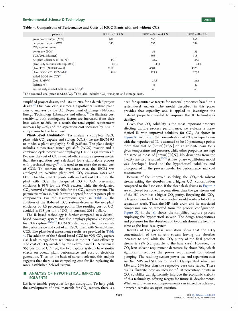
simplified project design, and 10% to 20% for a detailed projectdesign.38 Our base case assumes a hypothetical mature plant,akin to analyses by the U.S. Department of Energy’s NationalEnergy Technology Laboratory and others.50 To illustrate costsensitivity, both contingency factors are increased from theirbase values to 30%. As a result, the total capital requirementincreases by 29%, and the separation cost increases by 17% incomparison to the base case.Plant-Level Evaluation. To analyze a complete IGCC
plant with CO2 capture and storage (CCS), we use IECM 9.5to model a plant employing Shell gasifiers. The plant designincludes a two-stage water gas shift (WGS) reactor and acombined cycle power plant employing GE 7FB gas turbines.37
Because the cost of CO2 avoided offers a more rigorous metricthan the separation cost calculated for a stand-alone processwith purchased energy,49 it is used to measure the overall costof CCS. To estimate the avoidance cost, the IECM wasemployed to calculate plant-level CO2 emission rates andLCOE for Shell-IGCC plants with and without CCS. For theplant with CCS, the designated CO to CO2 conversionefficiency is 95% for the WGS reactor, while the designatedCO2 removal efficiency is 90% for the CO2 capture system. Theparametric values in default were adopted for other power plantcomponents. For the assumptions given in Table 2, theaddition of the IL-based CCS system decreases the net plantefficiency by 9.3 percentage points. The resulting cost of CO2avoided is $63 per ton of CO2 in constant 2011 dollars.The IL-based technology is further compared to a Selexol-
based two-stage system that also employs physical absorptionfor CO2 capture.
36,37,44 IECM 9.5 also was applied to evaluatethe performance and cost of an IGCC plant with Selexol-basedCCS. The plant-level assessment results are provided in Table4. The addition of the Selexol-based CCS for 90% CO2 capturealso leads to significant reductions in the net plant efficiency.The cost of CO2 avoided by the Selexol-based CCS system is$65 per ton of CO2. So, the two capture systems have similareffects on overall plant performance and cost of electricitygeneration. Thus, on the basis of current solvents, this analysissuggests that there is no compelling case for ILs replacing themore established Selexol system.
■ ANALYSIS OF HYPOTHETICAL IMPROVEDSOLVENTS
ILs have tunable properties for gas absorption. To help guidethe development of novel materials for CO2 capture, there is a
need for quantitative targets for material properties based on asystem-level analysis. The model described in this paperprovides that capability and is applied to investigate thematerial properties needed to improve the IL technology’sviability.Given that CO2 solubility is the most important property
affecting capture process performance, we evaluate a hypo-thetical IL with improved solubility for CO2. As shown inFigure S1 in the SI, the concentration of CO2 in equilibriumwith the hypothetical IL is assumed to be 10 percentage pointsmore than that of [hmim][Tf2N] on an absolute basis for agiven temperature and pressure, while other properties are keptthe same as those of [hmim][Tf2N]. No deviations from theideality are also assumed.51,52 A new phase equilibrium modelwas developed based on the hypothetical solubility andincorporated in the process model for performance and costassessments.Because of the improved solubility, the CO2-rich solvent
stream exiting the absorber has a higher CO2 concentrationcompared to the base case. If the three flash drums in Figure 2are employed for solvent regeneration, then the gas stream outof the HP drum has a higher CO2 purity. Recycling this CO2-rich gas stream back to the absorber would waste a lot of theseparation work. Thus, the HP flash drum and its associatedcompressor can be removed from the process configuration.Figure S2 in the SI shows the simplified capture processemploying the hypothetical solvent. The design temperaturesand pressures for the absorber and two flash drums are held thesame as the base case system.Results of the process simulation show that the CO2
concentration of the solvent stream leaving the absorberincreases to 46% while the CO2 purity of the final productstream is 98% (comparable to the base case). However, theCO2-lean solvent requirement decreases by about 70%, whichsignificantly reduces the power requirement for solventpumping. The resulting system power use and separation costare 34.6 MW and $12 per tonne of CO2 separated, which are35% and 29% less than the respective base case values. Theseresults illustrate how an increase of 10 percentage points inCO2 solubility can significantly improve the economic viabilityof this technology, offering targets for future IL developments.Whether and when such improvements can indeed be achieved,however, remains an open question.
Table 4. Comparisons of Performance and Costs of IGCC Plants with and without CCS
■ DISCUSSIONThis study has analyzed the use of [hmim][Tf2N] as a physicalsolvent for precombustion CO2 capture at IGCC power plants.The energy penalty of the IL-based system comes mainly fromthe process and product compression and solvent pumping,while the major capital cost components are the compressorsand absorbers. Both the parasitic load and cost vary to someextent with process design choices. The minimum cost ofseparation ($/ton CO2 separated from the syngas stream) forthe base case design was found to occur at a CO2 removalefficiency of 90%, indicating that a bypass design treating only aportion of the syngas would be cost-effective for an IL-basedsystem that required only partial CO2 capture (e.g., 50%removal). Comparisons of plant-level performance and costbetween IGCC plants employing [hmim][Tf2N]-based andSelexol-based capture systems showed very similar results,implying that an IL-based CCS system could be a viablealternative to current solvent processes.Advances in multiple areas are needed to improve the
viability of IL-based capture technology. Improvements in theCO2 solubility of ILs are needed to simplify the capture systemconfiguration and lower the energy penalty and cost for CO2capture. Novel compression technology also is needed tofurther reduce power needs and system cost. In addition, sincethe CO2 capture system accounts for less than 10% of an IGCCplant’s total capital requirement (see Table 4), large-scaledeployment of IGCC plants with CCS will require system-widecost reductions in other major plant components as well as inoverall plant integration, configuration, and design.Two further caveats accompany this study. First, the models
presented here do not consider the potential influence onprocess performance of other minor gas species such as watervapor and carbon monoxide. Second, to estimate the absorberpressure drop, this study employed mass transfer and pressuredrop rate correlations derived empirically for conventionalsolvents with lower viscosity than ILs. Thus, there is a need foradditional data in these areas to more rigorously evaluate theeffectiveness of ionic liquids as a cost-effective sorbent forprecombustion CO2 capture.
■ ASSOCIATED CONTENT*S Supporting InformationThe Supporting Information is available free of charge on theACS Publications website at DOI: 10.1021/acs.est.8b00411.
Additional text, tables, and figures on solvent and gasesproperties, phase equilibrium model parameters andvalidation, absorber design, major equipment power useor recovery, direct capital cost estimation, and modelingand analysis of a hypothetical improved solvent (PDF)
■ ACKNOWLEDGMENTSThis work was supported in part by Stanford University’sGlobal Climate and Energy Project. All opinions, findings,
conclusions, and recommendations expressed in this paper arethose of the authors alone and do not reflect the views of anyagencies.
■ REFERENCES(1) Brennecke, J. F.; Gurkan, B. E. Ionic liquids for CO2 capture andemission reduction. J. Phys. Chem. Lett. 2010, 1 (24), 3459−3464.(2) Ramdin, M.; de Loos, T. W.; Vlugt, T. J. State-of-the-art of CO2capture with ionic liquids. Ind. Eng. Chem. Res. 2012, 51 (24), 8149−81.(3) Theo, W. L.; Lim, J. S.; Hashim, H.; Mustaffa, A. A.; Ho, W. S.Review of pre-combustion capture and ionic liquid in carbon captureand storage. Appl. Energy 2016, 183, 1633−1663.(4) Zhang, X.; Zhang, X.; Dong, H.; Zhao, Z.; Zhang, S.; Huang, Y.Carbon capture with ionic liquids: overview and progress. EnergyEnviron. Sci. 2012, 5 (5), 6668−6681.(5) Zeng, S.; Zhang, X.; Bai, L.; Zhang, X.; Wang, H.; Wang, J.; Bao,D.; Li, M.; Liu, X.; Zhang, S. Ionic-liquid-based CO2 capture systems:structure, interaction and process. Chem. Rev. 2017, 117 (14), 9625−9673.(6) Lourenco, T. C.; Coelho, M. F.; Ramalho, T. C.; van der Spoel,D.; Costa, L. T. Insights on the Solubility of CO2 in 1-Ethyl-3-methylimidazolium Bis (trifluoromethylsulfonyl) imide from theMicroscopic Point of View. Environ. Sci. Technol. 2013, 47 (13),7421−7429.(7) Zhou, Y.; Liu, J.; Xiao, M.; Meng, Y.; Sun, L. Designing supportedionic liquids (ILs) within inorganic nanosheets for CO2 captureapplications. ACS Appl. Mater. Interfaces 2016, 8 (8), 5547−5555.(8) Gurkan, B.; Goodrich, B. F.; Mindrup, E. M.; Ficke, L. E.; Massel,M.; Seo, S.; Senftle, T. P.; Wu, H.; Glaser, M. F.; Shah, J. K.;Schneider, W. F. Molecular design of high capacity, low viscosity,chemically tunable ionic liquids for CO2 capture. J. Phys. Chem. Lett.2010, 1 (24), 3494−3499.(9) Seo, S.; Quiroz-Guzman, M.; DeSilva, M. A.; Lee, T. B.; Huang,Y.; Goodrich, B. F.; Schneider, W. F.; Brennecke, J. F. Chemicallytunable ionic liquids with aprotic heterocyclic anion (AHA) for CO2capture. J. Phys. Chem. B 2014, 118 (21), 5740−5751.(10) Seo, S.; Simoni, L. D.; Ma, M.; DeSilva, M. A.; Huang, Y.;Stadtherr, M. A.; Brennecke, J. F. Phase-change ionic liquids forpostcombustion CO2 capture. Energy Fuels 2014, 28 (9), 5968−5977.(11) Wappel, D.; Gronald, G.; Kalb, R.; Draxler, J. Ionic liquids forpost-combustion CO2 absorption. Int. J. Greenhouse Gas Control 2010,4 (3), 486−494.(12) Wang, X.; Akhmedov, N. G.; Duan, Y.; Luebke, D.; Hopkinson,D.; Li, B. Amino acid-functionalized ionic liquid solid sorbents forpost-combustion carbon capture. ACS Appl. Mater. Interfaces 2013, 5(17), 8670−8677.(13) Zhai, H.; Rubin, E. S. Systems analysis of ionic liquids for post-combustion CO2 capture at coal-fired power plants. Energy Procedia2014, 63, 1321−1328.(14) Hong, B.; Simoni, L. D.; Bennett, J. E.; Brennecke, J. F.;Stadtherr, M. A. Simultaneous process and material design for aproticn-heterocyclic anion ionic liquids in postcombustion CO2 capture. Ind.Eng. Chem. Res. 2016, 55 (30), 8432−8449.(15) Kenarsari, S. D.; Yang, D.; Jiang, G.; Zhang, S.; Wang, J.; Russell,A. G.; Wei, Q.; Fan, M. Review of recent advances in carbon dioxideseparation and capture. RSC Adv. 2013, 3 (45), 22739−22773.(16) Shiflett, M. B.; Yokozeki, A. Solubility of CO2 in roomtemperature ionic liquid [hmim][Tf2N]. J. Phys. Chem. B 2007, 111(8), 2070−2074.(17) Basha, O. M.; Keller, M. J.; Luebke, D. R.; Resnik, K. P.; Morsi,B. I. Development of a conceptual process for selective CO2 capturefrom fuel gas streams using [hmim][Tf2N] ionic liquid as a physicalsolvent. Energy Fuels 2013, 27 (7), 3905−3917.(18) Basha, O. M.; Heintz, Y. J.; Keller, M. J.; Luebke, D. R.; Resnik,K. P.; Morsi, B. I. Development of a conceptual process for selectivecapture of CO2 from fuel gas streams using two TEGO ionic liquids asphysical solvents. Ind. Eng. Chem. Res. 2014, 53 (8), 3184−3195.
(19) García-Gutierrez, P.; Jacquemin, J.; McCrellis, C.; Dimitriou, I.;Taylor, S. R.; Hardacre, C.; Allen, R. W. Techno-economic feasibilityof selective CO2 capture processes from biogas streams using ionicliquids as physical absorbents. Energy Fuels 2016, 30 (6), 5052−5064.(20) Vega, L. F.; Vilaseca, O.; Llovell, F.; Andreu, J. S. Modeling ionicliquids and the solubility of gases in them: recent advances andperspectives. Fluid Phase Equilib. 2010, 294 (1), 15−30.(21) Lei, Z.; Dai, C.; Chen, B. Gas solubility in ionic liquids. Chem.Rev. 2014, 114 (2), 1289−1326.(22) Damas, G. B.; Dias, A. B.; Costa, L. T. A quantum chemistrystudy for ionic liquids applied to gas capture and separation. J. Phys.Chem. B 2014, 118 (30), 9046−9064.(23) Chong, F. K.; Foo, D. C.; Eljack, F. T.; Atilhan, M.;Chemmangattuvalappil, N. G. (2015). Ionic liquid design for enhancedcarbon dioxide capture by computer-aided molecular design approach.Clean Technol. Environ. Policy 2015, 17 (5), 1301−1312.(24) Baghban, A.; Ahmadi, M. A.; Shahraki, B. H. Prediction carbondioxide solubility in presence of various ionic liquids usingcomputational intelligence approaches. J. Supercrit. Fluids 2015, 98,50−64.(25) Baghban, A.; Mohammadi, A. H.; Taleghani, M. S. Rigorousmodeling of CO2 equilibrium absorption in ionic liquids. Int. J.Greenhouse Gas Control 2017, 58, 19−41.(26) Lemmon, E. W.; McLinden, M. O.; Friend, D. G.Thermophysical Properties of Fluid Systems in NIST Chemistry Webbook,NIST Standard Reference Database Number 69; Linstrom, P. J.,Mallard, W. G., Eds.; National Institute of Standards and Technology:Gaithersburg MD, 2014. Available at http://webbook.nist.gov.(27) Fuller, E. N.; Schettler, P. D.; Giddings, J. C. New method forprediction of binary gas-phase diffusion coefficients. Ind. Eng. Chem.1966, 58 (5), 18−27.(28) Gurkan, B. E.; Gohndrone, T. R.; McCready, M. J.; Brennecke,J. F. Reaction kinetics of CO2 absorption into phosphonium basedanion-functionalized ionic liquids. Phys. Chem. Chem. Phys. 2013, 15(20), 7796−7811.(29) Yokozeki, A.; Shiflett, M. B. Hydrogen purification using room-temperature ionic liquids. Appl. Energy 2007, 84 (3), 351−361.(30) Raeissi, S.; Florusse, L. J.; Peters, C. J. Hydrogen solubilities inthe IUPAC ionic liquid 1-Hexyl-3-methylimidazolium bis (Trifluor-omethylsulfonyl) imide. J. Chem. Eng. Data 2011, 56 (4), 1105−1107.(31) Russell, R. A. A flexible and reliable method solves single-towerand crude-distillation-column problems. Chem. Eng. 1983, 90 (21),52−59.(32) Seader, J. D.; Henley, E. J.; Keith Roper, D. Separation ProcessPrinciples: Chemical and Biochemical Operations, 3rd ed.; John Wiley &Sons, Inc, 2011.(33) Strigle, Jr, R. F. Packed Tower Design and Applications: Randomand Structured Packings; Gulf Publishing: Houston, TX, 1994.(34) Towler, G.; Sinnott, R. K. Chemical Engineering Design:Principles, Practice and Economics of Plant and Process Design, 2nd ed.;Elsevier: Amsterdam, The Netherlands, 2013.(35) Onda, K.; Takeuchi, H.; Okumoto, Y. Mass transfer coefficientsbetween gas and liquid phases in packed columns. J. Chem. Eng. Jpn.1968, 1 (1), 56−62.(36) Chen, C.; Rubin, E. S. CO2 control technology effects on IGCCplant performance and cost. Energy Policy 2009, 37 (3), 915−924.(37) Chen, C. A Technical and Economic Assessment of CO2 CaptureTechnology for IGCC Power Plants, Ph.D. Dissertation; CarnegieMellon University: Pittsburgh, PA, 2005.(38) Technical Assessment Guide Vol.1: Electricity Supply, Rev.7;Report TR-102276-VIR7; Electric Power Research Institute: Palo Alto,CA, June 1993.(39) Updated Cost and Performance Estimates for Advanced CoalTechnologies Including CO2 Capture2009; Report No. 1017495;Electric Power Research Institute: Palo Alto, CA, 2009.(40) Berkenpas, M. B.; Kietzke, K.; Mantripragada, H.; McCoy, S.;Rubin, E. S.; Versteeg, P. L.; Zhai, H. Integrated Environmental ControlModel Technical Documentation Updates Final Report Vol. (IV): Updatesto PC and IGCC Plant Models; Prepared by Carnegie Mellon
University for the National Energy Technology Laboratory:Pittsburgh, PA, 2009.(41) Cost and Performance Baseline for Fossil Energy Plants; ReportDOE/NETL-2007/1281; U.S. Department of Energy’s NationalEnergy Technology Laboratory: Pittsburgh, PA, 2007.(42) Cost and Performance Baseline for Fossil Energy Plants. Rev.2;Report DOE/NETL-2010/1397; U.S. Department of Energy’sNational Energy Technology Laboratory: Pittsburgh, PA, 2010.(43) Cost and Performance Baseline for Fossil Energy Plants. Rev.2a;Report DOE/NETL-2010/1397; U.S. Department of Energy’sNational Energy Technology Laboratory: Pittsburgh, PA, 2013.(44) Integrated Environmental Control Model, Version 9.5; CarnegieMellon University: Pittsburgh, PA, 2017. Available at http://www.cmu.edu/epp/iecm/.(45) Rubin, E. S. Understanding the pitfalls of CCS cost estimates.Int. J. Greenhouse Gas Control 2012, 10, 181−190.(46) Rubin, E. S.; Berkenpas, M. B.; Frey, H. C.; Chen, C.; McCoy,S.; Zaremsky, C. J. Technical Documentation: Integrated GasificationCombined Cycle Systems (IGCC) with Carbon Capture and Storage(CCS). Prepared by Carnegie Mellon University for U.S. DOE/National Energy Technology Laboratory: Pittsburgh, PA, 2007.(47) Kumełan, J.; Tuma, D.; Maurer, G. Simultaneous solubility ofcarbon dioxide and hydrogen in the ionic liquid [hmim][Tf2N]:experimental results and correlation. Fluid Phase Equilib. 2011, 311,9−16.(48) Maginn, E. J. Ionic Liquids: Breakthrough Absorption Technologyfor Post-combustion CO2 capture, Subtask 19.2 Milestone Report: FinalSystem Analysis. Final Report for U.S. Department of Energy’s NationalEnergy Technology Laboratory: Pittsburgh, PA, 2013.(49) Zhai, H.; Rubin, E. S. Techno-economic assessment of polymermembrane systems for postcombustion carbon capture at coal-firedpower plants. Environ. Sci. Technol. 2013, 47 (6), 3006−3014.(50) Gerdes, K.; Stevens, R.; Fout, T.; Fisher, J.; Hackett, G.; Shelton,W. Current and future power generation technologies: pathways toreducing the cost of carbon capture for coal-fueled power plants.Energy Procedia 2014, 63, 7541−7557.(51) Carvalho, P. J.; Coutinho, J. A. On the nonideality of CO2solutions in ionic liquids and other low volatile solvents. J. Phys. Chem.Lett. 2010, 1 (4), 774−780.(52) Bara, J. E. Considering the basis of accounting for CO2 molefractions in ionic liquids and its influence on the interpretation ofsolution nonideality. Ind. Eng. Chem. Res. 2013, 52 (9), 3522−3529.