139
Systems Engineering for the Joint Capabilities Integration and Development System (JCIDS) Tutorial for the 9 th NDIA Systems Engineering Conference

Systems Engineering for the
Joint Capabilities Integration and Development System
(JCIDS)Tutorial for the 9th NDIA Systems Engineering
Conference

Briefing Date
slide 2
Agenda and Presenters
Introduction to JCIDS – Chris RyderApplying the Systems Engineering Method for JCIDS – Dave FlaniganModel-Driven Systems Engineering for JCIDS – Jennifer RaineyJCIDS Functional Analyses – Dave Krueger and Chris RyderSummary – Chris Ryder

Briefing Date
slide 3
Purpose of the Tutorial
JCIDS prescribes a joint forces approach to identify capability gaps against current force capability needsThe Systems Engineering (SE) Method applies to each iteration of the systems life-cycle from capability inception through system retirement Good systems engineering practice is necessary for successfully implementing JCIDSJCIDS Functional Analyses perform critical problem solving activitiesUse of model-driven SE facilitates JCIDS throughout the systems life-cycle

Briefing Date
slide 4
What is JCIDS?
• Capabilities-based assessment (CBA) composed of a structured
• Four-step methodology that defines capability gaps
• Capability needs and approaches to provide those capabilities within a specified functional or operational area.

Briefing Date
slide 5
JCIDS Is an Engineering Intensive Function
JCIDS activities are fundamental Systems Engineering actionso Consistent with the Systems Engineering Methodo Performed at early concept analysis and developmento But also at each capability upgradeJCIDS analysis quantifies material and non-material optionso Systems Engineering life-cycle phases quantifies the
phases of “Materialization”– Abstract concepts in early phases– Concrete systems and subsystems as the life
cycle progresses

Briefing Date
slide 6
JCIDS Process
*CJCSM 3170.01B
Joint Operations Concepts
Joint Operating ConceptsJoint Functional ConceptsJoint Integrating Concepts
Functional Area Analysis
FunctionalNeeds
Analysis
DOTLPFAnalysis
(Non-materielApproaches)
Ideas forMateriel
Approaches
Analysis ofMateriel/
Non-materielApproaches
Alternative NAlternative 2
Alternative 1JCD
CPD
CDD
ICD
DCR
IntegratedArchitectures
PostIndependent
Analysis
Functional Solution Analysis
DOD StrategicGuidance

Briefing Date
slide 7
JCIDS Events
Functional Area Analysis (FAA)o Identify operational task, conditions, and standards needed to
accomplish military objectiveso Result: Tasks to be accomplishedFunctional Needs Analysis (FNA)o Assess ability of current and programmed capabilities to
accomplish the taskso Result: List of capability gaps Functional Solutions Analysis (FSA)o Operational based assessment of DOTMLPF approaches to
solving capability gapso Result: Potential DOTMLPF approaches to capability gapsPost Independent Analysiso Independent analysis of approaches to determine best fito Result: Initial Capabilities Document
Briefing Date
slide 8
JCIDS
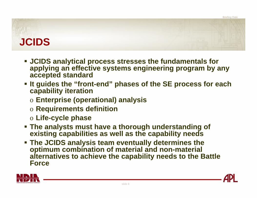
JCIDS analytical process stresses the fundamentals for applying an effective systems engineering program by any accepted standardIt guides the “front-end” phases of the SE process for each capability iterationo Enterprise (operational) analysis o Requirements definition o Life-cycle phaseThe analysts must have a thorough understanding of existing capabilities as well as the capability needs The JCIDS analysis team eventually determines the optimum combination of material and non-material alternatives to achieve the capability needs to the Battle Force

Briefing Date
slide 9
Perspective
Not an authoritative review of DoD policy and procedureso Chairman of the Joint Chiefs of Staff Instruction
(CJCSI) 3170.01, “Joint Capabilities Integration And Development System”
o Chairman of the Joint Chiefs of Staff Manual (CJCSM) 3170.01, “Operation of the Joint Capabilities Integration and Development System”
Relationship to the acquisition process
Discuss some thoughts on implementationo FAA, FNA, FSA, and PIAo No definitive cookbook for implementation

Briefing Date
slide 10
The JCIDS Meta-ModelOMG SysMLTM model of JCIDS activities and artifactso Activities
– FAA– FNA– FSA– PIA
o Artifacts– Architecture model
Including capability use cases– ICD, CDD, CPD– DOTMLPF Change Recommendations– Integrated Threat Warning Assessment (ITWA)– CONOPS
Briefing Date
slide 11
OMG SysMLTM
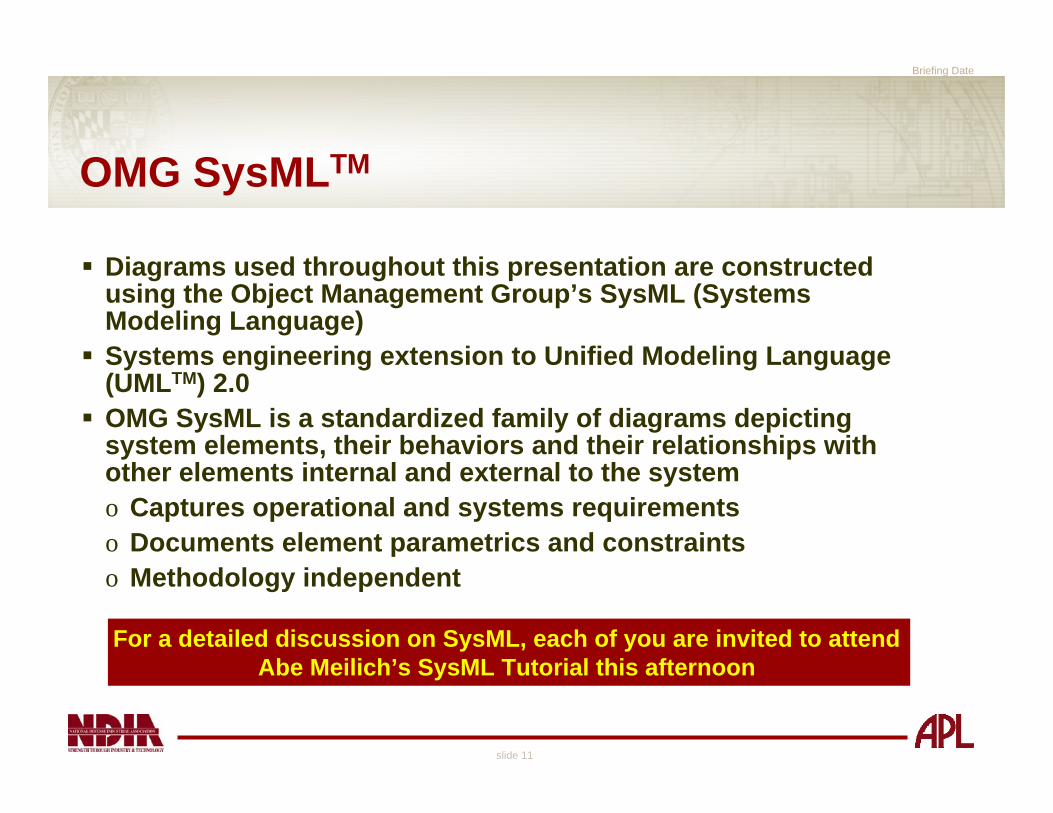
Diagrams used throughout this presentation are constructed using the Object Management Group’s SysML (Systems Modeling Language)Systems engineering extension to Unified Modeling Language (UMLTM) 2.0OMG SysML is a standardized family of diagrams depicting system elements, their behaviors and their relationships with other elements internal and external to the systemo Captures operational and systems requirementso Documents element parametrics and constraintso Methodology independent
For a detailed discussion on SysML, each of you are invited to attend Abe Meilich’s SysML Tutorial this afternoon

Briefing Date
slide 12
Targeting and Bomb Damage Assessment
Read the attached “Statement of Operational Need” at the breakTBDA represents a required capability to:o Maintain persistent coverage over a target areao Acquire fire-control quality track files on moving targetso Provide the means to determine whether a target was
sufficiently destroyed or neutralizedo Must be able to be deployed by a small team of ground-
based personnelo Controlled by the local ground commander
TBDA is a FICTICIOUS Case! Any similarity with any capability or system, real or imagined, is purely coincidental!

Briefing Date
slide 13
TBDA Presentation
This case presents a very limited sample of artifacts and elements that are part of the FAA, FNA and FSA SE ModelIntent is to illustrate modeling possibilities using SysMLo Requirements traceabilityo Entities with their behaviors and relationships
– Material and non-materialo Standards that govern architectural elements

Systems Engineering Method
David Flanigan
October 23, 2006
Briefing Date
slide 15
Discussion Topics
Describe Systems Engineering Method (SEM) in JCIDS contexto Identify and describe four “root” stepso Identify inputs/conditions for each stepo Identify outputs/products from each stepo Inter-relationships among the stepsShow linkage to JCIDS and the Systems Engineering lifecycle

Briefing Date
slide 16
Systems Engineering Method
Regardless of the analytical phase performed by the JCIDS SE team, o The basic application of the SE method is
constant throughout the process Each SE Method activity is performed in some form or to some degree in each phase of the system life-cycle

Briefing Date
slide 17
act Primary Use Cases
Requirements(Capability)
Analysis
FunctionalDefinition
PhysicalDefinition
DesignValidation
From Preceding Phase
To Next Phase
[Objectiv es]
[Requirements]
[Functions]
[System Model]
Systems Engineering Method
Adapted from Kossiakoff & Sweet “Systems Engineering Principles and Practice”
“Problem Space”
“Solution Space”
Measures of EffectivenessMeasures of
Effectiveness
Measures of PerformanceMeasures of Performance
Crossing the boundary from the problem space to the solution
space costs $$
Crossing the boundary from the problem space to the solution
space costs $$

Briefing Date
slide 18
Systems Engineering Method Over Life Cycle
The Systems Engineering “V” is iterative and
tailored throughout the entire lifecycle
Briefing Date
slide 19
Systems Engineering Method Over Life Cycle
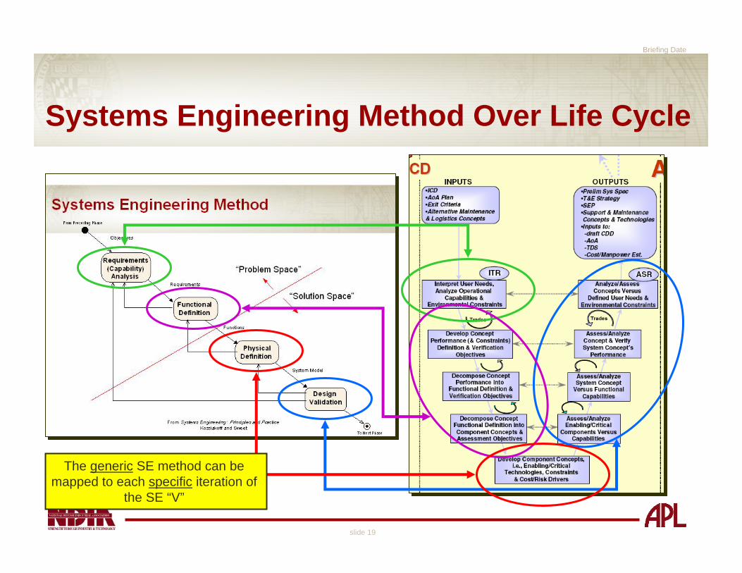
The generic SE method can be mapped to each specific iteration of
the SE “V”
Briefing Date
slide 20
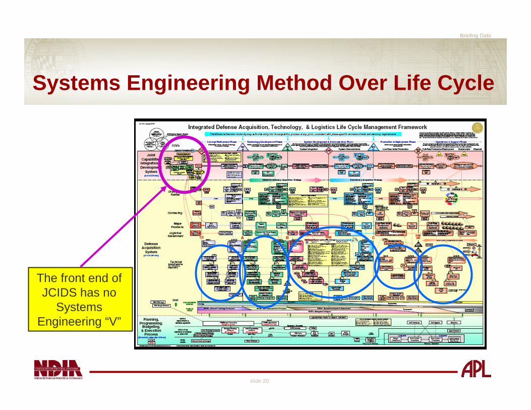
Systems Engineering Method Over Life Cycle
The front end of JCIDS has no
Systems Engineering “V”

Briefing Date
slide 21
Systems Engineering Method Over Life Cycle
Need to do good SE at the start of the
lifecycle, since each phase relies on
products from the previous phase
JCIDS is performed over the entire lifecycleJCIDS is performed over the entire lifecycle
Briefing Date
slide 22
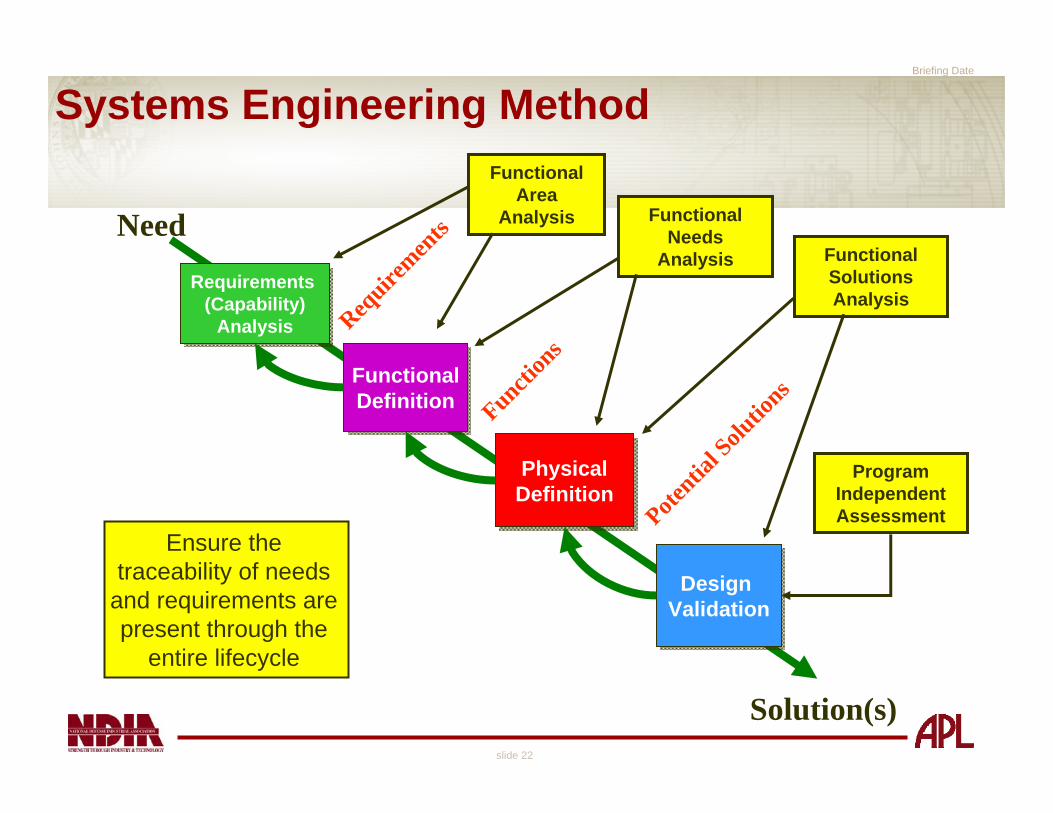
Systems Engineering Method
Need
Solution(s)
Requirements (Capability)
Analysis
Requirements (Capability)
Analysis
FunctionalDefinition
FunctionalDefinition
Design ValidationDesign
Validation
PhysicalDefinitionPhysical
Definition
Require
ments
Function
s
Potentia
l Solu
tions
Functional Area
Analysis Functional Needs
Analysis Functional Solutions Analysis
Program Independent Assessment
Ensure the traceability of needs
and requirements are present through the
entire lifecycle
Briefing Date
slide 23
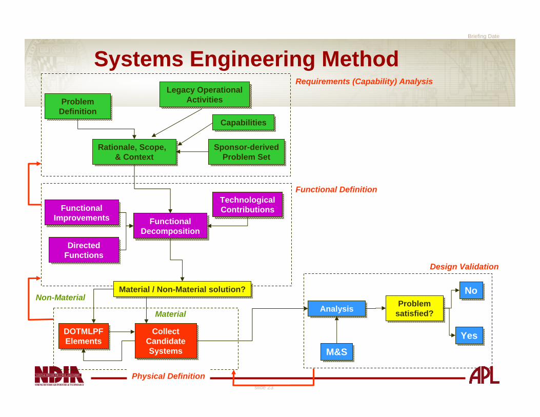
Systems Engineering Method
Problem DefinitionProblem
Definition
Rationale, Scope, & Context
Rationale, Scope, & Context
Functional Decomposition
Functional Decomposition
Legacy Operational Activities
Legacy Operational Activities
Sponsor-derivedProblem Set
Sponsor-derivedProblem Set
Technological Contributions
Technological Contributions
Directed FunctionsDirected
Functions
Functional Improvements
Functional Improvements
AnalysisAnalysis
M&SM&S
Problem satisfied?Problem
satisfied?
YesYes
NoNo
Requirements (Capability) Analysis
Functional Definition
Design Validation
CapabilitiesCapabilities
Collect Candidate Systems
Collect Candidate Systems
DOTMLPFElements
DOTMLPFElements
Material / Non-Material solution?Material / Non-Material solution?
Physical Definition
Non-Material
Material

Briefing Date
slide 24
Systems Engineering MethodPhase 1: Requirements (Capability) Analysis
Problem DefinitionProblem
Definition
Rationale, Scope, & Context
Rationale, Scope, & Context
Legacy Operational Activities
Legacy Operational Activities
Sponsor-derivedProblem Set
Sponsor-derivedProblem Set
Requirements (Capability) Analysis
CapabilitiesCapabilities
To Functional Analysis Phase
Briefing Date
slide 25
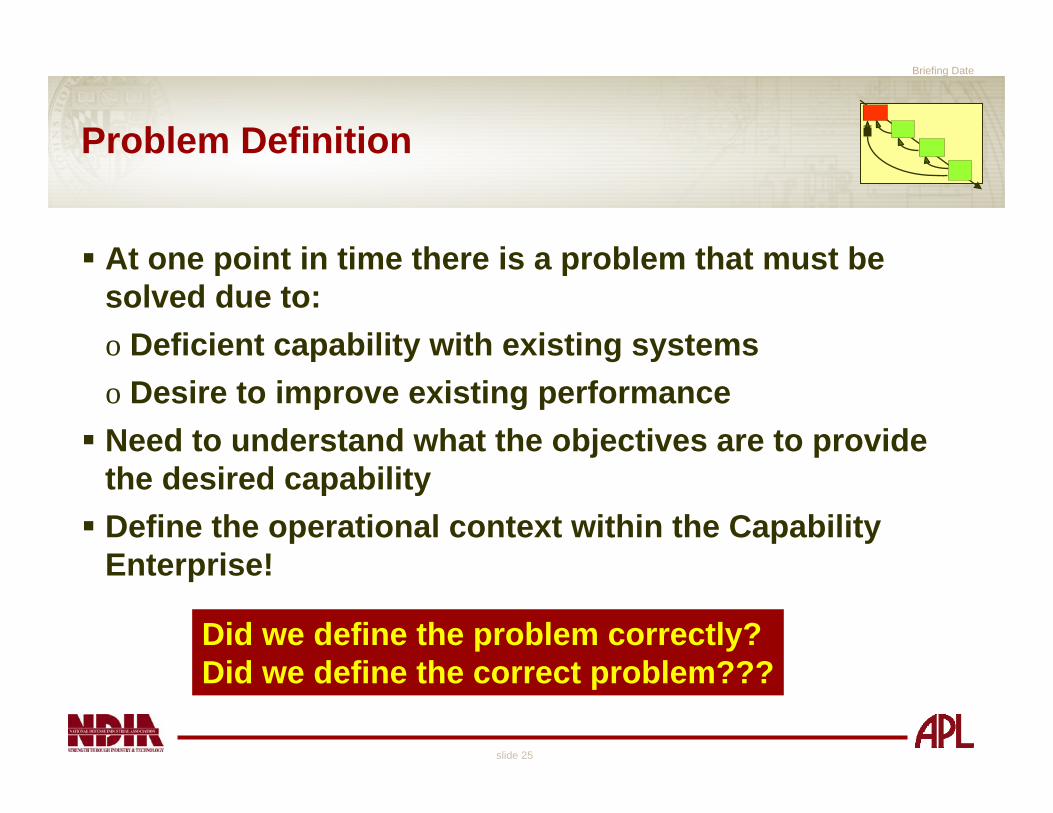
Problem Definition
At one point in time there is a problem that must be solved due to:o Deficient capability with existing systemso Desire to improve existing performanceNeed to understand what the objectives are to provide the desired capabilityDefine the operational context within the Capability Enterprise!
Did we define the problem correctly?Did we define the correct problem???
Briefing Date
slide 26
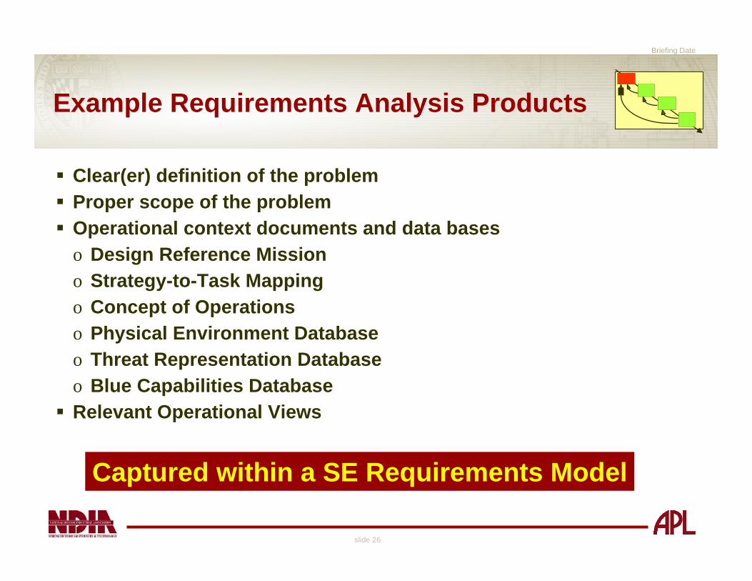
Example Requirements Analysis Products
Clear(er) definition of the problemProper scope of the problemOperational context documents and data baseso Design Reference Missiono Strategy-to-Task Mappingo Concept of Operationso Physical Environment Databaseo Threat Representation Databaseo Blue Capabilities DatabaseRelevant Operational Views
Captured within a SE Requirements Model

Briefing Date
slide 27
Systems Engineering MethodPhase 2: Functional Definition
Functional Decomposition
Functional Decomposition
Technological ContributionsTechnological Contributions
Directed FunctionsDirected
Functions
Functional Improvements
Functional Improvements
Functional Definition
From Requirements Definition
To Physical Definition

Briefing Date
slide 28
Typical Functional Definition Products
Functional Decomposition of required activitieso Functional diagrams (Functional Flow Block Diagrams, UML Activity
Diagrams)Associated metrics with these functions (threshold / objective)Analysis process that determines if you can solve with a material / non-material / both solutiono Be able to document and defend this processHow do we know it’s right?o The functions are legitimate, correct, and validated by usersFunctional Area AnalysisRelevant operational views
Functional Analysis Documented in a SE Functional or Physical Model
Briefing Date
slide 29
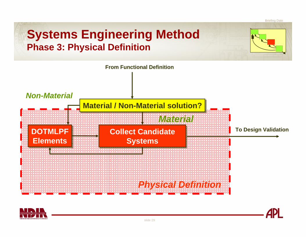
Systems Engineering MethodPhase 3: Physical Definition
Collect Candidate Systems
Collect Candidate Systems
DOTMLPFElements
DOTMLPFElements
Material / Non-Material solution?Material / Non-Material solution?
Physical Definition
Non-Material
Material
From Functional Definition
To Design Validation

Briefing Date
slide 30
Typical Physical Definition Products
Provide system alternatives towards satisfying required functionalityo Assignment of functions to physical elementsDOTMLPF analysis productso Based on the functional definition phaseCONOPS changes / recommendationso Based on DOTMLPF analysisRisk management strategies of the systemSystem roadmaps to bridge the gap between the current and futurecapabilitiesFunctional Needs AnalysisRelevant operational and SYSTEMS views
SE Physical Model with Physical Definition Begins Evolution Toward a Systems Model

Briefing Date
slide 31
Systems Engineering MethodPhase 4: Design Validation
AnalysisAnalysis
M&SM&S
Problem satisfied?Problem
satisfied?
YesYes
NoNo
Design Validation
Reassess requirements,
functional elements or physical details
To next life-cycle phase: Requirements
Definition
From Physical Definition

Briefing Date
slide 32
Typical Design Validation Products
Demonstrate the analysis documents the assumptions, follows a rigorous process, and arrives at meaningful conclusions that arejustifiableo There may be multiple processes and products dependent on the
sponsor, personnel/time availability, experienceo This may be an iterative process for ICD, CDD, CPDTrade studiesVV&ARisk ManagementCost AnalysisForce AllocationFunctional Solutions AnalysisProgram Independent Assessment
Attain a Fully Validated Systems Engineering Model
Briefing Date
slide 33
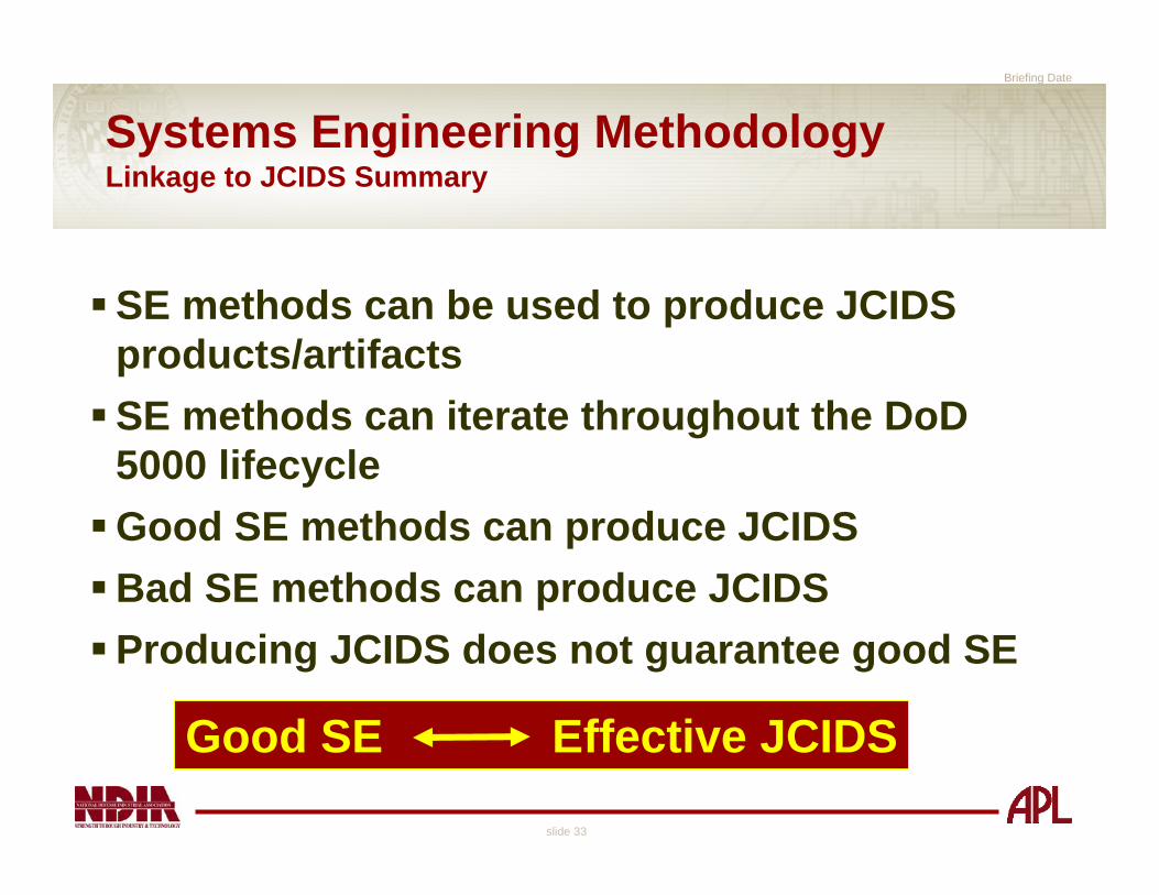
Systems Engineering Methodology Linkage to JCIDS Summary
SE methods can be used to produce JCIDS products/artifactsSE methods can iterate throughout the DoD 5000 lifecycleGood SE methods can produce JCIDSBad SE methods can produce JCIDSProducing JCIDS does not guarantee good SE
Good SE Effective JCIDS

Applying Model-Driven Systems Engineering
Practices to JCIDS
Jennifer Rainey
October 23, 2006
Briefing Date
slide 35
Discussion Topics
Purpose –a model-driven systems engineering (MDSE) approach supports the JCIDS lifecycle process
What is Model-Driven Systems Engineering?
How to Apply Model-driven Systems Engineering for JCIDS?

Briefing Date
slide 36
PurposeA Model Driven Systems Engineering (MDSE) approach supports the entire defense acquisition, technology, and logistics lifecycleo A systems engineering model provides traceability from system
development back to initial JCIDS process and war fighting needo MDSE focuses on techniques that drive capability identification
– Documents entire system lifecycle– Identifies the capabilities, capability gaps, and materiel/non-materiel
solutions– Develops foundation for integrated architectures
o JCIDS is a concept-centric capabilities identification process– “The process to identify capability gaps & potential material and
non-materiel solutions must be supported by a robust analytical process that incorporates innovative practices…”
CJCSI 3170.01E 11 May 2005
Use of model-driven SE facilitates JCIDS throughout the systems lifecycle

Briefing Date
slide 37
Integrated Defense Acquisition, Technology, & Logistics Lifecycle Management Framework
MDSE is used here
MDSE should be used here

Briefing Date
slide 38
Systems Engineering ModelA model is a representation of a systemo Assists stakeholders, including engineers, to understand something that
is not easily comprehensibleo Communicates the organization of the system to stakeholderso Enhances understanding of interfaces, relationships, operations and risko Continually updated
Systems Engineering Modelo Build as the basis for JCIDS analysiso Covers the problem and solution spaceo Contains the objects, relationships and the data
– Requirements, Functional, and Physicalo Develops the integrated architecture
Systems Engineering Model is a Living Entity

Briefing Date
slide 39
Model-Driven Systems Engineering
Establish system model bases on:o Requirements modelo Functional modelo Physical model
Show relationships between the modelso Link operational needs to capabilitieso Link capabilities to requirementso Link requirements to functionso Link functions to systems
Understand the capability being developed“If you don’t model it, you won’t understand it.”Ivar Jacobson

Briefing Date
slide 40
act Primary Use Cases
Requirements(Capability)
Analysis
FunctionalDefinition
PhysicalDefinition
DesignValidation
From Preceding Phase
To Next Phase
[Objectiv es]
[Requirements]
[Functions]
[System Model]
Systems Engineering Method
Requirements Model
Functional Model
Physical Model
Building blocks of an integrated architecture
Adapted from Kossiakoff & Sweet “Systems Engineering Principles and Practice”

Briefing Date
slide 41
Requirements ModelRequirements Analysiso Define/scope the problem spaceo Identify “capabilities” during JCIDS process to meet war fighting needs
– Capabilities turn into requirements later in the lifecycleo Analyze capabilities/requirements
– Assess against “as-is” capabilities/systems, identify gaps– Ensure they are necessary, concise, attainable, complete,
consistent, unambiguous, and verifiable– Create requirements traceability
o Products:– Framework for Operational Views
Fulfill need to develop DoDAF operational view artifactsSets standards to be used needed for technical view artifacts
– MetricsMeasures of EffectivenessMeasures of Performance
– Operational context documents

Briefing Date
slide 42
Functional ModelFunctional Definitiono Implementation free identification of required activitieso Establish functional decomposition
– Use Cases, Operational Scenarios– Functional Flow Block Diagrams (FFBDs)– Unified Modeling Language (UML) Activity Diagrams
o Can model the time sequencing of the functionso Show data or information flow between functions
– Fulfill need to develop DoDAF operational view artifacts– Fulfill need to develop DoDAF system view artifacts
o Products:– Capabilities/functionality needed to meet requirements– Refined performance metrics– Framework for Operational and System Views

Briefing Date
slide 43
Physical ModelPhysical Definition – solution spaceo Set the system context or boundary
– Context diagrams– Class diagrams
Allocate functions to physical elements– Evaluate “to-be” capabilities against “as-is” capabilities and
systems to identify the “capability gaps” and “redundancies”– Establish link to requirements
Products:– System Elements– Relevant system views– System data exchanges– System roadmaps to bridge the capability gap
Formed the Systems Engineering Model

Briefing Date
slide 44
The Systems Engineering ModelWhere it all ties together!o Formed by establishing the relationships between the requirements, functional, and
physical elements of the model– Requirements (capabilities) link to functions, functions are allocated to
physical componentsEarly in the process, the system solution can be expressed as a “black box”As the lifecycle advances, the physical model is further refined into sub-systems
◦ Ensure every requirement is linked to a function◦ Ensure every function is allocated to physical element
– The MDSE process forms the basis for the integrated architectureo Supports impact analysis
– The SE Model developed during upfront JCIDS is the same model used during the entire acquisition lifecycle
– Traceability is maintained back to the original capability need identifiedAllows greater understanding of the impact of how changing one element in the model, impacts other areas

Briefing Date
slide 45
MDSE Basis for Integrated Architectures
Joint Operations Concepts
Joint Operating ConceptsJoint Functional ConceptsJoint Integrating Concepts
Functional Area Analysis
FunctionalNeeds
Analysis
DOTLPFAnalysis
(Non-materielApproaches)
Ideas forMateriel
Approaches
Analysis ofMateriel/
Non-materielApproaches
Alternative NAlternative 2
Alternative 1
JCD
CPD
CDD
ICD
DCR
IntegratedArchitectures
PostIndependent
Analysis
Functional Solution Analysis
DOD StrategicGuidance

Briefing Date
slide 46
Architectures in JCIDS“Integrated Architectures” are a foundation for the analytical processo Stated requirements, attributes, and measureso Meets DoDAF needso Used during upfront JCIDS, concept refinement, technology
development, system integration, system development, and production
o System model defines the architecture used during the lifecycle
“Key components of the CDD and CPD are the integrated architecture products that ensure the DoD understands the linkages between capabilities and systems and can make appropriate acquisition decisions.” CJCSI 3170.01E 11 May 2005
The “Systems Model” becomes the basis for architecture and JCIDS analysis
Briefing Date
slide 47
Architecture Views
Architecture Viewso A view is a different “slice” of the modelo Provides a look “inside” the modelo Includes information relevant to the stakeholder
An architecture engenders a multitude of artifactso Most are derived using the same information and data elements
– Can be obtained from the systems engineering modelo DoDAF architecture views are specific types of artifacts
– Includes Operational, Systems, and Technical Viewso DoDAF architecture views are just a few of the possible model
views

Briefing Date
slide 48
JCIDS Systems Engineering ModelA Systems Engineering model captures the essential elements of the systems engineering life-cycle
“Dynamic and recursive process” (Bootch, Rumbaugh, Jacobson)o Iteratively captures enterprise capabilities and system
requirementso Promotes incorporation of technology evolution
Forms basis for sound, long-term systems engineering and analysiso Compliant with DoDAF and JCIDS
Model-Driven SE in Defense Systems Acquisition becomes Model-Driven JCIDS

Briefing Date
slide 49
How to Apply MDSE to JCIDS
Establish a meta-model to understand the framework for the process
Meta-model is another abstraction, highlighting the properties of a modelo Explicit description (constructs and rules) of how a
domain-specific model is built
JCIDS meta-model is composed of:o Dynamic elements – modeling the behavior over timeo Logical elements – static view of the objects and
classes
Need to model JCIDS process as a “meta-model”
Briefing Date
slide 50
The JCIDS Meta-ModelDynamic Componento Incorporates model-driven analyses within the JCIDS processo Standardizes SE modeling methods demonstrate utility for modeling
JCIDS capabilitieso Applies the model-driven approach to each JCIDS analytical phase
– Leading up to JCIDS analyses documentation– Appropriate for capability iterations throughout the Warfare
Systems’ livesEasily updated and maintainedUse throughout the acquisition lifecycle
Logical Componento The Capability Object exists within the “Capability Enterprise”o Captures logical and dynamic elementso Identifies the attributes and operations of a Capability Object
functioning within the operational domaino Identifies “Non-Materiel” elements of DOTMLPF

Briefing Date
slide 51
JCIDS Meta-Model Dynamic Component
FAA, FNA, FSA, and PIA are represented as use caseso Each phase represents a dynamic set of activitieso With post-condition “Result of Value”
Relates the JCIDS activities to the process of SE/Architecture modelingo Understanding the As-Is Enterprise and evolving the
To-Be mission scenarios and use cases

Briefing Date
slide 52
JCIDS Dynamic Model
Perform FAA
Perform FNA
Perform FSA
Capability Sponsor
Conduct PIA
Capability Object<<Capability>>

Briefing Date
slide 53
JCIDS Meta-Model Logical
Focus of analysis is on a Capability Objecto Enables itself within the Capability EnterpriseIdentification of needed capabilities to fulfill war fighting needs (FAA)Baseline Capability Enterprise is composed of As-Is capabilities of legacy As-Is Warfare SystemComparison of To-Be capabilities against the As-Is baseline yields the Capability Gap(s) (FNA)Evolve the capability and allocate to physical To-Be Warfare System (FSA)DOTMLPF applies needs analysis and potential solutions

Briefing Date
slide 54
Capability Object
Form of “System Object” as defined by Object Oriented Systems Engineering Methods (OOSEM)o Performs operations on behalf of itself and/or other
objects– Provide output result of value– Provide services and information related elements
within the domaino Possesses measurable properties
– Physical, data, performance
Capability Objects, like all UML classes, possess:o Attributeso Operationso Associations

Briefing Date
slide 55
Capability Object and the Warfare Systemclass Capabilities Enterprise
«capability»Capability Enterprise
«system»Warfare System
«capability»Cabability
Object
+ Attributes:
+ Tasks()
DOTMLPF
«system»System As-Is
«system»System To-Be
«capabili ty»Capability As-Is
«capabil ity»Capability To-Be
DOTMLPF As-Is DOTMLPF To-BE
Assigned to
Component of
+Affected/Enhanced by
+Supports/Affects
Briefing Date
slide 56
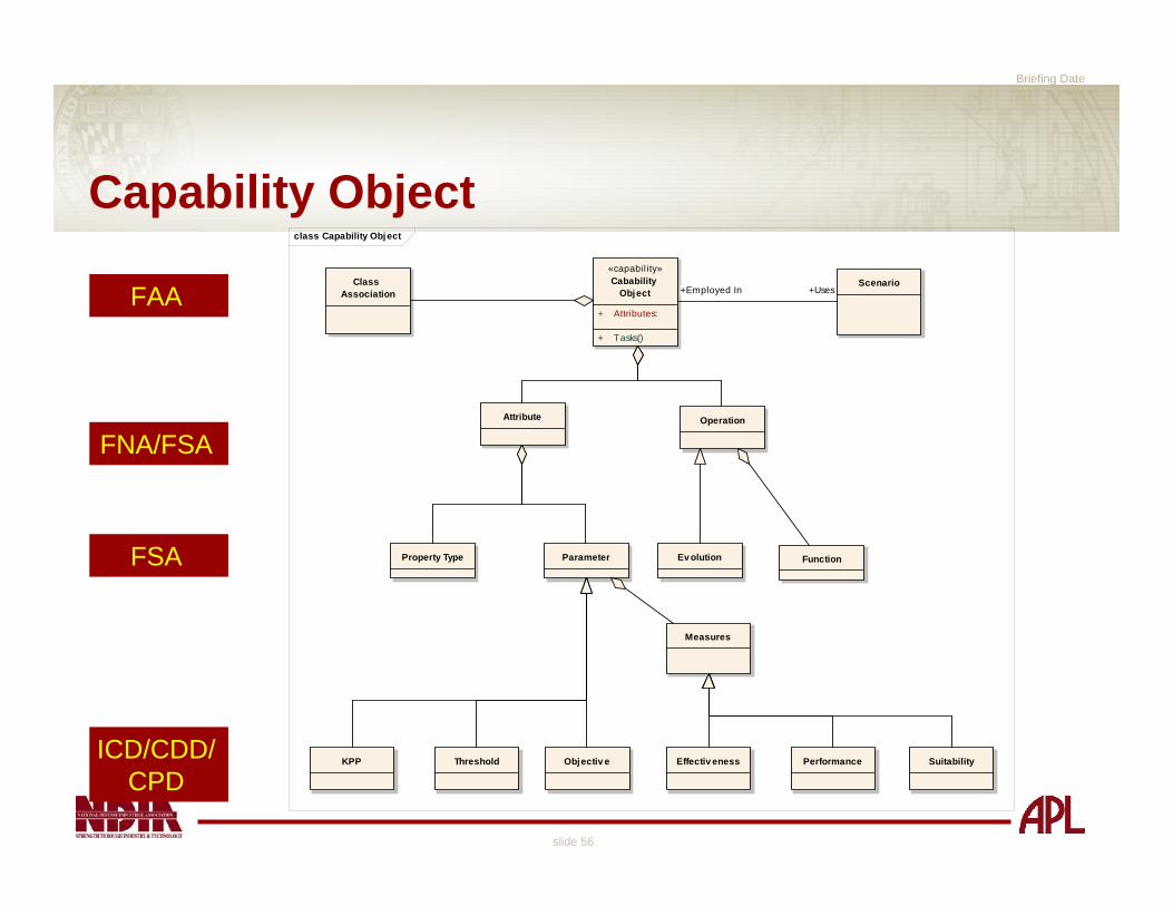
Capability Objectclass Capability Object
«capabil ity»Cabability
Object
+ Attributes:
+ Tasks()
Class Association
Scenario
Attribute Operation
Property Type Parameter
Measures
Ev olution Function
Effectiv eness Performance SuitabilityKPP Threshold Objectiv e
+Employed In +UsesFAA
FNA/FSA
FSA
ICD/CDD/CPD

Briefing Date
slide 57
Transition from Capability to System
Use capability object to perform assessments to satisfy DOTMLPFo Analysis of Materiel/non-materiel approacheso Analysis of Alternativeso Initial Capability DocumentInvestigate if a modification to any element of DOTMLPF
except the “M” will enhance the Capability Enterpriseo A far less expensive optionDOTMLPF elements can be modeled as classeso Each non-materiel element possess attributes and
operationso Helpful to define a meta-class early in the process to
understand element components and relationship

Briefing Date
slide 58
Transition from Capability to Systemclass Capability Transition
DOTMLPF
«capability»Capability Gap
«system»System As-Is
«capabil ity»Capability As-Is
«capabil ity»Capability To-Be
«system»System To-Be
+Applies To
+Applies To
+Assigned To
+Assigned To
+Satifies
+Possesses
+Evolves To
The Legacy System DOTMLPF can also transition from “As-Is” to “To-Be”

Briefing Date
slide 59
act Primary Use Cases
Requirements(Capability)
Analysis
FunctionalDefinition
PhysicalDefinition
DesignValidation
From Preceding Phase
To Next Phase
[Objectiv es]
[Requirements]
[Functions]
[System Model]
Model-driven Approach Facilitates JCIDS
Building blocks of an integrated architecture
FAA
FNA
FSA
PIA
Adapted from Kossiakoff & Sweet “Systems Engineering Principles and Practice”

Briefing Date
slide 60
Benefits of Model-Driven Approach
Traceable back to initial FAA and war fighting needo Changes to system requirements can be evaluated against the “to-be”
capability identified during FAA, FNA, and FSA– Ensures solution implemented meets intent of JCIDS analysis
One place to document entire system lifecycle from inception to deploymento Document rationale for decisions and analysiso Easily supports changes/updates to the model while maintaining
historical informationo Abstracts the complexities of the warfare system, the capability system,
and associated elements such that a team can effectively grasp them
Appropriate integrated architecture views can be generatedo Operational views – requirements and functional modelo System views – physical modelo Technical views – requirements, physical models

Briefing Date
slide 61
SummaryModel-driven SE will provide robust lifecycle system modelo Provides integrated architectureo Supports initial capabilities assessmento Establishes framework for entire lifecycle: concept
refinement, technology development, system development and demonstration, production and deployment, and operations and support phases
Systems Engineering methodology enhances the JCIDS processo Models abstract complexities of modern warfare systemsComprehensive models provide for compilation of data needed to assess capabilities and comply with JCIDS
Models bridge the diverse knowledge domains of the warrior and the engineer

Functional Area Analysis (FAA)Functional Needs Analysis (FNA)
Functional Solutions Analysis (FSA)
Dave KruegerChris Ryder
Contributions from Lee Kennedy and Bob Finlayson

Briefing Date
slide 63
JCIDS Process*
*CJCSM 3170.01B
Joint Operations Concepts
Joint Operating ConceptsJoint Functional ConceptsJoint Integrating Concepts
Functional Area Analysis
FunctionalNeeds
Analysis
DOTLPFAnalysis
(Non-materielApproaches)
Ideas forMateriel
Approaches
Analysis ofMateriel/
Non-materielApproaches
Alternative NAlternative 2
Alternative 1JCD
CPD
CDD
ICD
DCR
IntegratedArchitectures
PostIndependent
Analysis
Functional Solution Analysis
DOD StrategicGuidance

Briefing Date
slide 64
The Defense Acquisition Management Framework*
IOCBAConcept
RefinementSystem Development
& DemonstrationProduction &Deployment
Systems Acquisition
Operations &Support
C
Sustainment
• Process entry at Milestones A, B, or C• Entrance criteria met before entering phase• Evolutionary Acquisition or Single Step to
Full Capability
FRP DecisionReview
FOC
LRIP/IOT&EDesign
ReadinessReview
TechnologyDevelopment
(ProgramInitiation)
ConceptDecision
Pre-Systems Acquisition
*DoDI 5000.2, 12 May 2003
ApprovedInitial Capabilities
Document (ICD)& Analysis of
Alternatives (AoA) Plan
ApprovedCapability Development
Document (CDD)
ApprovedCapability Production
Document (CPD)
Completed AoA

Briefing Date
slide 65
The Defense Acquisition Management Framework

Briefing Date
slide 66
Discussion Topics
Perspective
Introduction to the TBDA Case
Functional area analysis (FAA)
Functional needs analysis (FNA)
Functional solutions analysis (FSA)
Post independent analysis (PIA)
Conclusion

Briefing Date
slide 67
JCIDS Process
*CJCSM 3170.01B
Joint Operations Concepts
Joint Operating ConceptsJoint Functional ConceptsJoint Integrating Concepts
Functional Area Analysis
FunctionalNeeds
Analysis
DOTLPFAnalysis
(Non-materielApproaches)
Ideas forMateriel
Approaches
Analysis ofMateriel/
Non-materielApproaches
Alternative NAlternative 2
Alternative 1JCD
CPD
CDD
ICD
DCR
IntegratedArchitectures
PostIndependent
Analysis
Functional Solution Analysis
DOD StrategicGuidance

Briefing Date
slide 68
Defining the Problem Space
Functional Area Analysis (FAA)
Produces a list of capabilities across all functional areas necessary to achieve military objectives
Capabilities o Operational taskso Conditionso Standards (or measures of effectiveness)
Inputo National strategies, JOCs, JFCs, JICs, the Universal
Joint Task List (UJTL)o Anticipated adversary capabilities
Briefing Date
slide 69
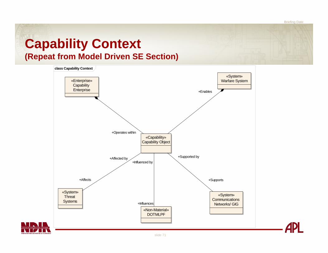
Defining the Problem SpaceThe Capability Context
Understanding the Capability Enterpriseo Environmento Enemy forces and systems Capability operations Capability operators (Warriors)Network requirementsCapability command and controlo Command authorityAnalysis of legacy Warfare Systems contributing to the Capability ObjectPreliminary Non-Materiel issueso DOTMLPF analysis primarily occurs during the FSA

Briefing Date
slide 70
Architecture Meta-Modelclass Architecture Model
«DataType»Architecture Model
Architecture Element
Architecture View
Physical Element
Dynamic Element
Association
«DataType»Functional
Model
Physical Model
«DataType»Requirements
Model
«DataType»Requirements
Traceability Matrix
Architecture Depicts
Briefing Date
slide 71
Capability Context(Repeat from Model Driven SE Section)
class Capability Context
«Capability»Capability Object
«Enterprise»Capability Enterprise
«System»Warfare System
«System»Threat Systems
«System»Communications Networks/ GIG
«Non-Material»DOTMLPF
+Affects
+Affected by
+Supports
+Supported by
+Influences
+Influenced by
+Operates within
+Enables

Briefing Date
slide 72
FAA Activity Diagramact Perform FAA
National strategies, JOC, JFC, JIC, UJTL, and the anticipated range of broad capabilities that adversaries might employ.
The basis for Mission Level Use Cases and Scenarios.
These tasks are foundation of "To-Be" Enterprise Model.
ID tasks for FNA
Environmental conditions, timeline, threat analysis
Analyze OperatingConditions
Understanding the legacyCapabiltiy "As Is" contribution to the needed "To-Be" capabilities.
Perform Cross-Capability andCross-Section Analysis
Information Gathering
Collect RelevantCapability Artifacts
«DataType»Capability Task List
- Measure 1..N: - Mission 1..N: - Standard: - Task 1..N: - Traceability to National Strategy:
«DataType»UJTL
- Operational: OP-1..N- Strategic: National : SN-1..N- Strategic: Theater : ST-1..N- Tactical : TA-1..N
«DataType»JCIDS Document
«Capability»Capability As Is
- Attribute 1..N:
+ Operation 1..N() : ROV
«DataType»Architecture Model
Includes preliminary Capability requirements (operational needs), actors (warriors), tasks (activities) and Capability Context.
«DataType»Joint Capability
Area

Briefing Date
slide 73
FAA Approach
FAA
Joint OperationsConcepts (JOpsC)• Fully Integrated• Expeditionary• Networked• Decentralized• Adaptable• Decision superiority• Lethality
Joint OperatingConcepts (JOC)• Homeland Security• Stability Operations• Strategic Deterrence• Major Combat Operations
Joint FunctionalConcepts (JFC)• Force application• Force protection• Focused logistics• Battlespace awareness• Command and control• Force management• Net centric• Joint training
Joint IntegratingConcepts (JIC)• Forceable Entry Ops• Undersea Superiority• Global Strike Ops• Sea-Basing Ops• Air & Missile Defense• JC2• Joint Logistics
Universal Joint Task List (UJTL)• Strategic National (SN)• Strategic Theater (ST)• Operational (OP)• Tactical (TA)
Universal Navy Task List (UNTL)• UJTL (Strategic & Operational)• Navy Tactical Task List (NTTL)
Program SpecificDocumentation
Other Input• Operational personnel• CustomersRequired Capabilities
Applicable, Existing FAAs• Battlespace Awareness FAA

Briefing Date
slide 74
Joint Operations Concepts (JOpsC)
An overarching description of how the future Joint Force will operate across the entire range of military operations
Attributeso Fully Integratedo Expeditionaryo Networkedo Decentralizedo Adaptableo Decision superiorityo Lethality
Too general for specific FAA development

Briefing Date
slide 75
Joint Integrating Concepts (JICs)
Description of how a Joint Force Commander will integrate capabilities to generate effects and achieve an objectiveo Forceable Entry Opso Undersea Superiorityo Global Strike Opso Sea-Basing Opso Air & Missile Defenseo JC2o Joint Logistics
Includes an illustrative CONOPS for a specific scenario and a set of distinguishing principles applicable to a range of scenarios

Briefing Date
slide 76
Joint Operating Concepts (JOCs)
Operational-level description of how the Joint Force Commander will operate and a foundation for defining military capabilities
Operational context for JFC and JIC developmento Homeland Security (HLS)o Stability Operations (SO)o Strategic Deterrence (SD)o Major Combat Operations (MCO)

Briefing Date
slide 77
Joint Functional Concepts (JFCs)Describes how the joint force will perform military functions across the range of military operationsFunctional areas o Force applicationo Force protectiono Focused logisticso Battlespace awarenesso Command and controlo Force managemento Net centrico Joint training
Functional Capability Board (FCB)for each functional area
Briefing Date
slide 78
Functional Capability Boards (FCB)Responsible for organization, analysis, and prioritization of capability needs proposals within their functional areas
Provide oversight and assessment throughout JCIDS processo Reduce redundant analyseso Ensure consistency in capability definitionso Ensure approaches consider a broad range of possibilities
Provides context briefing to JROCo Where capability proposal fits within functional area
Make recommendations on validation and approval
Identify appropriate FCB and involve them in the analyses!

Briefing Date
slide 79
Battlespace Awareness JFCCapabilities
Operationalo Command and control of BA assetso Execute collectiono Exploitation and analysiso M&S, forecasto Manage knowledgeEnablingo Integrate BA networko Infuse emergent technologyo Recruit, retain, train
Several capabilities IDed for each capability category, e.g., • Surveillance• Cross cue• Employ human resources• Employ open source resources• Measure & monitor environmental
conditions
“Functional Concept for Battlespace Awareness,” 31 December 2003, p. 85.
Briefing Date
slide 80
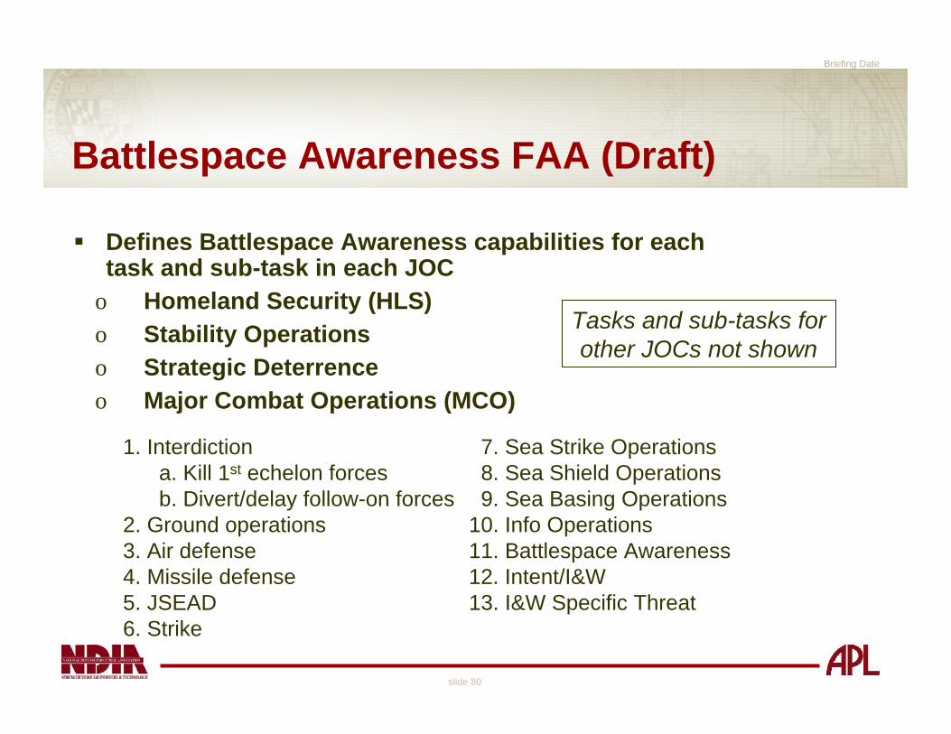
Battlespace Awareness FAA (Draft)
Defines Battlespace Awareness capabilities for each task and sub-task in each JOC
o Homeland Security (HLS)o Stability Operationso Strategic Deterrenceo Major Combat Operations (MCO)
1. Interdiction 7. Sea Strike Operationsa. Kill 1st echelon forces 8. Sea Shield Operationsb. Divert/delay follow-on forces 9. Sea Basing Operations
2. Ground operations 10. Info Operations3. Air defense 11. Battlespace Awareness4. Missile defense 12. Intent/I&W5. JSEAD 13. I&W Specific Threat6. Strike
Tasks and sub-tasks forother JOCs not shown

Briefing Date
slide 81
UJTL and UNTL
UJTL: “The Universal Joint Task List (UJTL), when augmented with the Service task lists, is a comprehensiveintegrated menu of functional tasks, conditions, measures, and criteria supporting all levels of the Department of Defense in executing the National Military Strategy.”
UNTL : “The UNTL tasks make up a comprehensive hierarchical structure. The UNTL task list is designed to be comprehensive while being mutually exclusive. When reviewing the levels of the hierarchy, the subordinate tasks will, in total, comprehensively, and without redundancy, define all activities involved in the next higher-level task.”

Briefing Date
slide 82
* CJCSM 3500.04C, “Universal Joint Task List (UJTL),” 1 July 2002
Universal Joint Task List (UJTL)*Levels of War
(SN) Strategic level - National military taskso Accomplish objectives of national military strategy(ST) Strategic level - Theater taskso Accomplish objectives of the theater and campaign
strategy(OP) Operational level taskso Accomplish objectives of subordinate campaigns and
major operations(TA) Tactical level tasks - include joint/interoperability tactical tasks and the applicable Service taskso Accomplish objectives of battles and engagements

Briefing Date
slide 83
NTA Navy Tactical
NTA 1 Deploy Forces/Conduct Maneuver NTA 2 Develop Intelligence NTA 2.1 Plan and Direct Intelligence Operations NTA 2.2 Collect Data and Intelligence NTA 2.2.1 Collect Target Information NTA 2.2.2 Collect Tactical Intelligence on Situation NTA 2.2.3 Perform Tactical Reconnaissance and Surveillance NTA 2.2.4 Assess Tactical Environment NTA 2.3 Process and Exploit Collected Info/Intelligence NTA 2.3.1 Conduct Technical Processing and Exploitation NTA 2.3.2 Correlate Information NTA 2.4 Produce Intelligence NTA 2.5 Disseminate and Integrate Intelligence NTA 3 Employ Firepower NTA 4 Perform Logistics and Combat Service Support NTA 5 Exercise Command and Control NTA 6 Protect the Force
UNTLExample Hierarchy
To obtain, by various detection methods, information about the activities of an enemy or potential enemy or tactical area of operations. This task uses surveillance to systematically observe the area of operations by visual, aural, electronic, photographic, or other means. This includes development and execution of search plans.
To associate and combine data on a single subject to improve the reliability or credibility of the information. This task includes collating information (identifying and grouping related items of information for critical comparison).

Briefing Date
slide 84
Identify Tasks for FNAact ID tasks for FNA
Select Tasksfrom UJTL
Select Tasksfrom FCBPortfolio
«DataType»UJTL
- Strategic: National : SN-1..N- Strategic: Theater : ST-1..N- Operational: OP-1..N- Tactical : TA-1..N
Define Standards andConditions for Each
Task
«DataType»Task Measures List
- Measure 1..N:
«DataType»Capability Task List
- Task 1..N:

Briefing Date
slide 85
Identify Tasks
FAA
Joint OperationsConcepts (JOpsC)• Fully Integrated• Expeditionary• Networked• Decentralized• Adaptable• Decision superiority• Lethality
Joint OperatingConcepts (JOC)• Homeland Security• Stability Operations• Strategic Deterrence• Major Combat Operations
Joint FunctionalConcepts (JFC)• Force application• Force protection• Focused logistics• Battlespace awareness• Command and control• Force management• Net centric• Joint training
Joint IntegratingConcepts (JIC)• Forceable Entry Ops• Undersea Superiority• Global Strike Ops• Sea-Basing Ops• Air & Missile Defense• JC2• Joint Logistics
Universal Joint Task List (UJTL)• Strategic National (SN)• Strategic Theater (ST)• Operational (OP)• Tactical (TA)
Universal Navy Task List (UNTL)• UJTL • Navy Tactical Task List (NTTL)
Program SpecificDocumentation
Other Input• Operational personnel• CustomersRequired Capabilities
Applicable, Existing FAAs• Battlespace Awareness FAA
Universal Navy Task List (UNTL)• UJTL • Navy Tactical Task List (NTTL)
Identify tasks

Briefing Date
slide 86
Select Tasks from UJTL & UNTL
NTA Navy Tactical Y NTA 1 Deploy Forces/Conduct Maneuver P NTA 2 Develop Intelligence Y NTA 2.1 Plan and Direct Intelligence Operations N NTA 2.2 Collect Data and Intelligence Y NTA 2.2.1 Collect Target Information Y NTA 2.2.2 Collect Tactical Intelligence on Situation Y NTA 2.2.3 Perform Tactical Reconnaissance and Surveillance Y NTA 2.2.4 Assess Tactical Environment Y NTA 2.3 Process and Exploit Collected Info/Intelligence Y NTA 2.3.1 Conduct Technical Processing and Exploitation Y NTA 2.3.2 Correlate Information Y NTA 2.4 Produce Intelligence Y NTA 2.5 Disseminate and Integrate Intelligence P NTA 3 Employ Firepower P NTA 4 Perform Logistics and Combat Service Support N NTA 5 Exercise Command and Control P NTA 6 Protect the Force P

Briefing Date
slide 87
Select Tasks from FCB Portfolios
Manage Knowledge
Model, Simulate, Forecast/Predict
Exploit and Analyze
Execute Collection
Command and Control of BA Assets
Battlespace Awareness Tasks
NContent management
NShare plan visibility
YSmart pull/push information
NIntegrate adversary and friendly information
NPredictive analysis
PDefeat denial and deception
NEnable analyst collaboration
YInformation fusion
NDistribute processing
YRecognize targets
PMeasure and monitor environmental conditions
NEmploy open source resources
YEmploy human resources
YCross cue
YSurveillance
NTask, dynamically re-task and monitor assets
YSynchronize ISR with operations
Applicable

Briefing Date
slide 88
Define Conditions and Standardsfor Each Task
Conditions - a variable of the environment that affects performance of a tasko Physical: land, sea, air, spaceo Military: mission; forces; C3; intelligence; deployment,
movement, and maneuver; firepower; protection; sustainment; threat; conflict
o Civil: political policies, culture, economy, Standard - the minimum proficiency required in the performance of a tasko Measure - Quantitative or qualitative basis for describing the
quality of task performanceo Criterion - A critical, threshold, or specified value of a
measureSourceso UJTL/UNTLo Design Reference Mission (DRM)o Subject Matter Experts (SMEs)

Briefing Date
slide 89
Example Conditions From UNTLC 1.0 PHYSICAL ENVIRONMENTo C 1.1 LAND
– C 1.1.1 TerrainC 1.1.1.1 Terrain ReliefC 1.1.1.2 Terrain ElevationC 1.1.1.3 Terrain SlopeC 1.1.1.4 Terrain FirmnessC 1.1.1.5 Terrain TractionC 1.1.1.6 VegetationPlants, trees, and shrubs.Descriptors: Jungle (rainforest, canopied); Dense (forested); Light (meadow, plain); Sparse (alpine, semi-desert); Negligible (arctic, desert).C 1.1.1.7 Terrain Relief features
– C 1.1.2 Geological Features– C 1.1.3 Man-Made Terrain Features– Etc.

Briefing Date
slide 90
Example MeasuresNTA 2.2.3 Perform Tactical Reconnaissance and Surveillance
To obtain, by various detection methods, information about the activities of an enemy or potential enemy or tactical area of operations. This task uses surveillance to systematically observe the area of operations by visual, aural, electronic, photographic, or other means. This includes development and execution of search plans.
To exploit single tasked image collected after aircraft on deckTime
Operational availability of tactical aircraft reconnaissance systems
PercentTo respond to emergent taskingHoursOf time able to respond to collection requirementsPercent
Of collection requirements fulfilled by reconnaissance/surveillance assets
Percent
From receipt of tasking, until reconnaissance/surveillance assets in place
DaysMeasureUnits

Briefing Date
slide 91
Mission Type 1Standard 1.1.1Standard 1.1.2
Task 1.2 Standard 1.2Task 1.3 Standard 1.3Task 1.4 Standard 1.4
Standard 1.5.1Standard 1.5.2Standard 1.5.3
Mission Type 2Mission Type 3Mission Type 4
FAA
Task 1.5
Task 1.1
FAA ResultsDescription of the operational/tactial situation including the appropriate conditions
Description of the task, e.g., “Perform tactical reconnaissance and surveillance”
3 days from receipt of tasking, until reconnaissance/surveillance assets in place
6 hours to exploit single tasked image collected after aircraft on deck

Briefing Date
slide 92
FAA Artifacts
First iteration of Architecture Modelo Capability Requirements Modelo Capability Context Diagram
– Block Definition Diagramo Identification of actors within the Capability Enterprise
– Block Definition Diagramo Capability tasks depicted in Use Case Diagram
– And Activity Diagram as appropriate

Briefing Date
slide 93
FAA Artifacts
First Iteration of Architecture Modelo Initial information exchanges and data elements
– Sequence Diagramo Tasks can be captured as SysML Blocks that include
task standards – Task attributes (measures)– Results of Value (Post-Conditions that determine
success/failure)Capability Task Listo Capability tasks trace to model elements, including
capability requirements

Briefing Date
slide 94
TBDA FAADefine the operational enterprise for the TBDA that will:o Establish measurable capability needs for targeting and
surveillance o Specify the pertinent operations for targeting and
surveillance that will capture the correct capability taskso Comprehend the “Capability Enablers”, those “things”
that provide pieces of the overall capability– Including initial review of legacy systems– As well as non-materiel contributors
o Who are the beneficiaries of the capabilityo What are the potential data elements, information
exchanges and interfaceso Verify that the capability is required and that it is captured
correctly
Briefing Date
slide 95
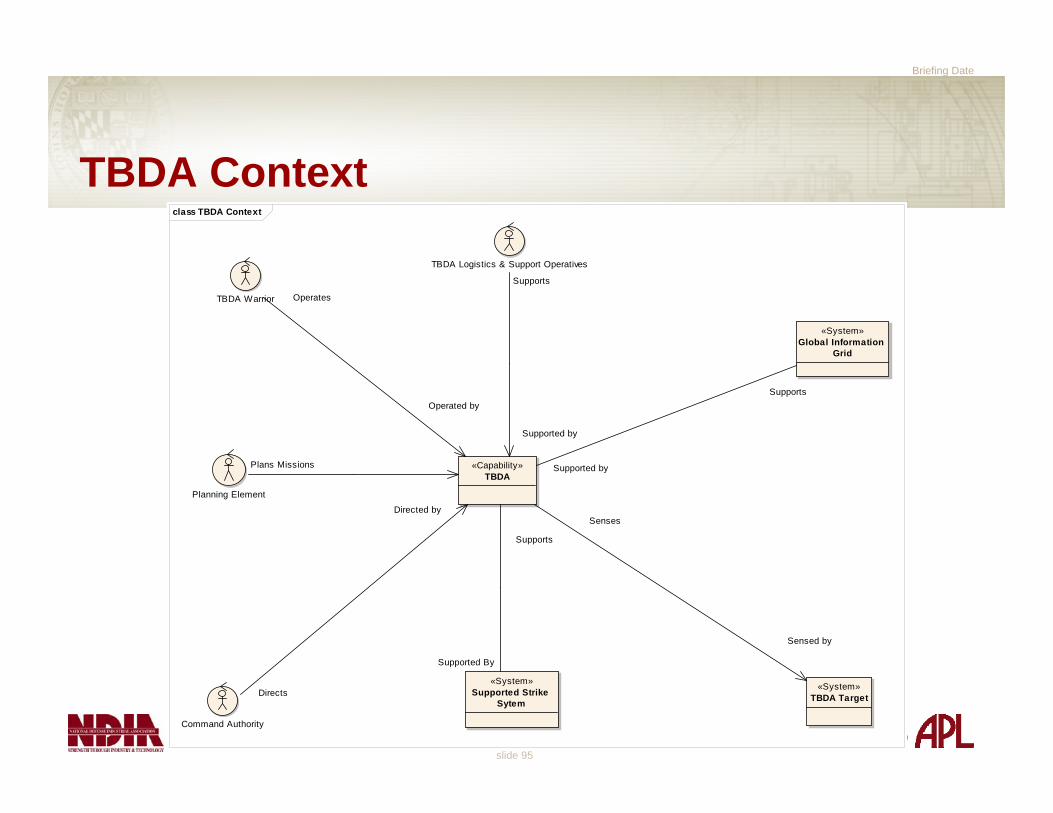
TBDA Contextclass TBDA Context
«Capability»TBDA
TBDA Warrior
TBDA Logistics & Support Operatives
Command Authority
«System»TBDA Target
«System»Global Information
Grid
Planning Element
«System»Supported Strike
Sytem
Plans Missions
Directs
Directed by
Supports
Supported by
Operates
Operated by
Supports
Supported By
Supported by
Supports
Senses
Sensed by

Briefing Date
slide 96
TBDA Context
At this point in the analysis, the TBDA :o Is under the direction of some Command Authorityo Senses a generic class of targetso Interfaces with the Global Information Grido Operated by Warriorso Supported and maintained by WarriorsIt is highly probable that he Capability Context will be modified throughout the FAA (and follow-on analysis phases)

Briefing Date
slide 97
TBDA Capability Elements(The FAA Requirements Model)
Four basic needs categorieso Networking/ Data Link
– TBDA Information must “get somewhere”o Sensors
– Some “thing” must capture TBDA informationo Vehicle
– The capability must be deployed within a defined battespace
o Supportability and Logistics– “Professionals think Logistics”
Requirements can be captured using data bases and graphical toolso Requirements Traceability Matrix (RTM)o SysML Requirements Diagramo These artifacts must be “tightly coupled”

Briefing Date
slide 98
TBDA FAA Requirements Diagramreq TBDA Requirements
TBDA System
Area of Coverage
(from Vehicle)
Range for Coverage
(from Vehicle)
Time of Flight
(from Vehicle)
Vehicle
(from Vehicle)
Target Resolution
(from Sensors)
Target Radar Cross Section
(from Sensors)
Sensor Range
(from Sensors)
Range of Speeds for Target Tracking
(from Sensors)
Number of Targets for Simultaneous Track
(from Sensors)
Field of View
(from Sensors)
Field of Regard
(from Sensors)
Vehicle Launch and Landing
(from Logistics and Supportability)
System Set-up Time
(from Logistics and Supportability)
Mean Time for Maintenance Action
(from Logistics and Supportability)
Mean Flight Hours Between Maintenance Actions
(from Logistics and Supportability)
Range of Coverage for Data Link
(from Data Link )
Data Transfer Rate
(from Data Link )
Bandwidth
(from Data Link )
SysML diagrams supported by robust database

Briefing Date
slide 99
TBDA Fundamental Operations
SysML Use Case Diagram Captures Basic Functionality Performed by Actors
uc TBDA
TBDA Warrior
Collect,Process and Assess Surveillance
Information
Develop the TBDA
Surveillance Mission
Disseminate TBDA Information
Support and Sustain TBDATBDA Logistics & Support Operatives
«Capability»TBDA
Transport TBDA
Command Authority
Planning Element

Briefing Date
slide 100
Fundamental Operations Function Tree
class TBDA Functional Hierarchy
«Use Case»Conduct TBDA
Mission
«Use Case»Develop the TBDA
Surveillance Mission
«Use Case»Transport the TBDA
«Use Case»Collect, Process and Assess Surveillance
Information
«Use Case»Disseminate the TBDA
Information
«Use Case»Support and Sustain
the TBDA

Briefing Date
slide 101
TBDA Functional Decomposition(Develop the TBDA Mission)
act Mission Development
Collect RelevantPre-flight Data
Conduct PreliminaryMission Analysis
DevelopCommunications
Network
Develop SensorPlan
Develop VehicleOperations Plan
Develop IntegratedPre-Mission Plan
Comm PlanSensor Plan
Vehicle Plan
Mission Plan
«DateType»Operational Information
«DataType»TBDA Mission
Tasking
Download MissionPlan to TBDA
Vehicle

Briefing Date
slide 102
TBDA Functional Analysis(Initial Data Exchanges)
sd Mission Development
CommandAuthority
MissionDevelopment
Team
TBDA WarriorTBDASupportingElements
Mission Tasking
Request Operational Information
Operational Information
Mission Plan Ready for Download to TBDA

Briefing Date
slide 103
SysML Diagrams Supporting Functional Analysis
Activity Diagramo Depicts functional elements as activities
– Activities create Data Elements that are consumed in subsequent activities or use cases
– Team can assess initial data requirements– Data Element is most often the Result of Value (ROV)
o Modified to show “who” is performing the activities via “swim lanes”
Sequence Diagram (aka Interaction Diagram)o Depicts sequence of information exchanges
– Sending and receiving nodeso Analysis team should be able to get an initial
understanding of interface requirements
Activities and Use Cases Trace to UNTL Tasks
Briefing Date
slide 104
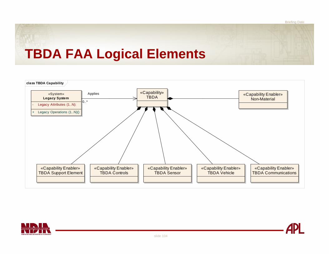
TBDA FAA Logical Elements
class TBDA Capability
«Capability»TBDA
«Capability Enabler»TBDA Sensor
«Capability Enabler»TBDA Vehicle
«Capability Enabler»TBDA Communications
«Capability Enabler»TBDA Controls
«Capability Enabler»TBDA Support Element
«Capability Enabler»Non-Material
«System»Legacy System
- Legacy Attributes (1..N):
+ Legacy Operations (1..N)()
Applies
0..*

Briefing Date
slide 105
TBDA FAA Block Definition Diagram
Even during the FAA, some “Capability Enablers” can be logically deducedo As analysis progresses, the attributes for these
Enablers will be defined as well as functionality assigned to those elements
Acknowledged that there are some non-materiel contributorsInitial review of legacy systemso Further studied during FNA
Briefing Date
slide 106
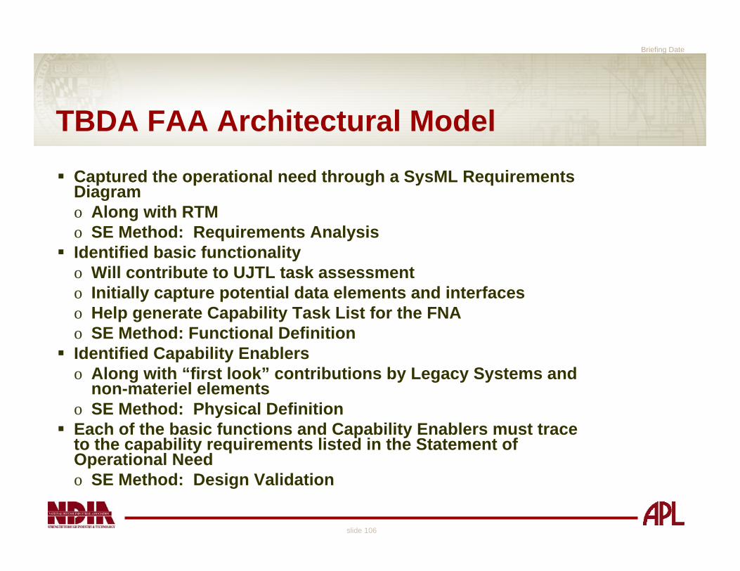
TBDA FAA Architectural ModelCaptured the operational need through a SysML Requirements Diagramo Along with RTMo SE Method: Requirements AnalysisIdentified basic functionalityo Will contribute to UJTL task assessmento Initially capture potential data elements and interfaceso Help generate Capability Task List for the FNAo SE Method: Functional DefinitionIdentified Capability Enablerso Along with “first look” contributions by Legacy Systems and
non-materiel elementso SE Method: Physical DefinitionEach of the basic functions and Capability Enablers must trace to the capability requirements listed in the Statement of Operational Needo SE Method: Design Validation

Briefing Date
slide 107
JCIDS Process
*CJCSM 3170.01B
Joint Operations Concepts
Joint Operating ConceptsJoint Functional ConceptsJoint Integrating Concepts
Functional Area Analysis
FunctionalNeeds
Analysis
DOTLPFAnalysis
(Non-materielApproaches)
Ideas forMateriel
Approaches
Analysis ofMateriel/
Non-materielApproaches
Alternative NAlternative 2
Alternative 1JCD
CPD
CDD
ICD
DCR
IntegratedArchitectures
PostIndependent
Analysis
Functional Solution Analysis
DOD StrategicGuidance

Briefing Date
slide 108
Determines gaps in planned capabilities
Functional Needs Analysis (FNA)Assess current and programmed warfighting systems
o Can they deliver the capabilities identified in the FAAo Uses conditions from FAAo Uses standards from the FAA as the “measuring stick”
Outputo List of capability gaps or shortfalls
– Relative priority– Timeframe for required solutions
o Identify redundancies in capabilities that reflect inefficiencies.
Briefing Date
slide 109
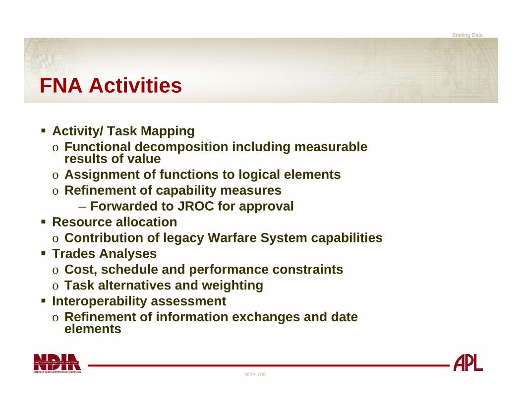
FNA Activities
Activity/ Task Mappingo Functional decomposition including measurable
results of valueo Assignment of functions to logical elementso Refinement of capability measures
– Forwarded to JROC for approvalResource allocationo Contribution of legacy Warfare System capabilitiesTrades Analyseso Cost, schedule and performance constraintso Task alternatives and weightingInteroperability assessmento Refinement of information exchanges and date
elements

Briefing Date
slide 110
FNA Functional Analysis
Expand functional analysis from FAAIdentify data elements/ data attributesConsider interface elements such as communications linksQuantify measurable use case results of value Functional contributions of legacy systems and subsystems

Briefing Date
slide 111
Functional Analysis with Use Cases
Use Caseo Sequence of events that returns a measurable Result
of Value (Booch, Rumbaugh, Jacobson)o Captures
– Actors (Warriors performing the activities)Roles, not specific individuals or commands
– Activities (operations)– Data objects
Created and consumed by the activitiesInformation elements that are exchanged between the Operational Nodes
– Any other relevant references such as UJTL tasks
Functional Analysis is basic to the Systems Engineering Method

Briefing Date
slide 112
FNA Activity Diagramact Perform FNA
Identify Key Architectural Elementsaffected by new capability
Formulate key attributes for capabilitydevelopment of Measures of
Effectiveness
Analyze potential new FunctionalAreas for problem or solution
Assess Capability Gaps, Overlapsand operational problem(s)
«DataType»Capability Task List
- Mission 1..N: - Task 1..N: - Standard: - Measure 1..N: - Traceability to National Strategy:
«DataType»Capability Gap List
- Capability Gap 1..N:
«DataType»Capability Element
- Weight: - Risk:
«DataType»Architecture Model
«DataType»Capability Measure
«DataType»Resource List
- Financial Resources: Money- Warfare Systems: - Support Systems:
«DataType»Capability Attribute
«DataType»Functional
Model
«DataType»Use Case
«DataType»Use Case ROV
«DataType»Capability Task
Weight
«DataType»From FAA :
Architecture Model
JROCApproved
1..*

Briefing Date
slide 113
Example FNA Methodology
Alternative A Alternative B Alternative CScore Score Score
Mission Type 1 0.30 0.79 0.79 0.69Standard 1.1.1 0.10 0.90 0.80 0.85Standard 1.1.2 0.05 0.85 0.90 0.60
Task 1.2 Standard 1.2 0.15 0.90 0.70 0.70Task 1.3 Standard 1.3 0.30 0.80 0.80 0.80Task 1.4 Standard 1.4 0.10 0.50 0.50 0.40
Standard 1.5.1 0.05 0.70 0.70 0.50Standard 1.5.2 0.20 0.75 0.95 0.70Standard 1.5.3 0.05 0.95 0.90 0.50
Mission Type 2 0.30 0.90 0.70 0.80Mission Type 3 0.30 0.80 0.90 0.70Mission Type 4 0.10 0.70 0.90 0.60
0.82 0.81 0.72
Weight
Composite Score
FAA
Task 1.5
Task 1.1
1. Assign weights based on relative importance
2. Select alternatives (screen based on FAA)
3. Evaluate performance of each alternative for each mission, task, and standard
4. Scores less than one indicate capability gaps

Briefing Date
slide 114
FNA Artifacts
Next iteration of Architecture Model includingo Definition of Capability Elements
– Model as Blocks including attributes, parameters and constraints
o Definition of legacy systems that contribute to the capability
o Capturing functional tasks as use cases with ROVs o Assignment of functional tasks to Capability (logical)
Elements o Use cases assigned to Capability Elements as Block
operationsCapability measures forwarded to JROC for approvalRequirements Traceability Matrix
Briefing Date
slide 115
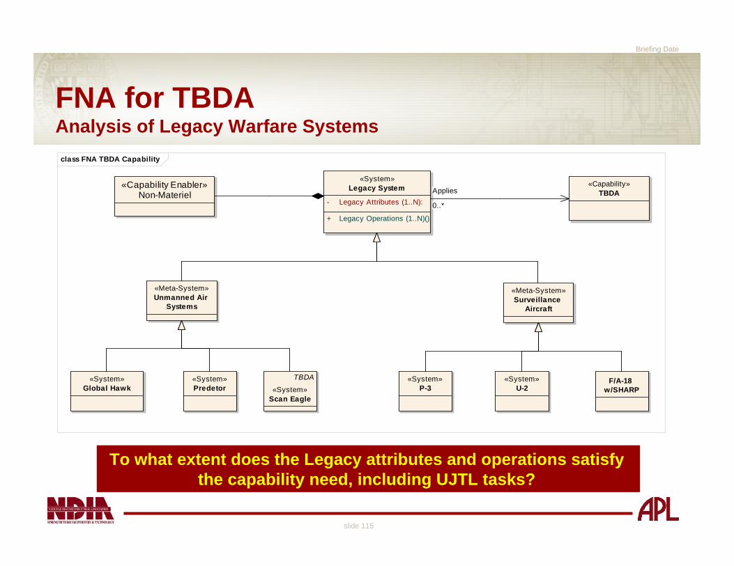
FNA for TBDAAnalysis of Legacy Warfare Systems
To what extent does the Legacy attributes and operations satisfythe capability need, including UJTL tasks?
class FNA TBDA Capability
«Capability»TBDA
«System»Legacy System
- Legacy Attributes (1..N):
+ Legacy Operations (1..N)()
«System»Global Hawk
«System»Predetor
«Meta-System»Unmanned Air
Systems
TBDA
«System»Scan Eagle
«Meta-System»Surveillance
Aircraft
«System»U-2
«System»P-3
F/A-18 w/SHARP
«Capability Enabler»Non-Materiel Applies
0..*

Briefing Date
slide 116
FNA for Capability Enablers
Existing subsystems/ components with suitable performance
measures may provide some
capability requirements,
but will need to be integrated into an overall
solution
class Sensors
«Capability Enabler»TBDA Sensor
- Field of Regard: - Field of View: - Number of Targets to Track: int- Sensor Range:
«Capability Enabler»RF Sensor
«Capability Enabler»EO/IR Sensor
«DataType»RF Target Track
- Position: - Velocity: - Resolution Error:
«DataType»EO/IR Target Track
- Position: - Resolution Error:
What is the Track File Quality? Is it sufficient for the capability requirement? What are the PerformanceMeasures?
Target Resolution
(from Sensors)
Generates Generates
Satisfies?Satisfies?

Briefing Date
slide 117
Key Architectural Elements
In the FNA, architectural elements are still abstractions (i.e. capability enablers) of real systemsArchitectures include behaviors, relationships AND rules for “rules governing their design over time” (DoDAF)o FNA is the time to consider the “possible” with regard
to applications for the capability enablers– Including the standards that govern the
applicationExample, TBDA Communicationso Tactical application places limits on size, weight, range
of operationso Logical conclusion (after analysis): Comm
Applications limited to Link-16, UHF/ VMF and CDL– Standardized interfaces exist for those
applications– Modeled using SysML Internal Block Diagram

Briefing Date
slide 118
TBDA FNA Communications Architecture
composite structure Comm_Interfaces
«System»Global Information Grid
Link-16/ Mil-Std-6016
UHF/VMF/ Mil-Std-6017
CDL
«Capability Enabler»TBDA Communications
Link-16/ Mil-Std-6016
UHF/ VMF/ Mil-Std-6017
CDL
UHF/ VMF
Linik-16
Common Data Link
Port: Interface defined by Standard
Briefing Date
slide 119
TBDA FNA Model
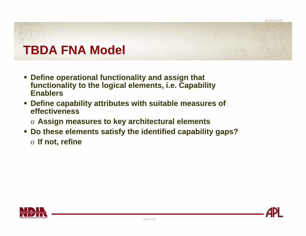
Define operational functionality and assign that functionality to the logical elements, i.e. Capability EnablersDefine capability attributes with suitable measures of effectiveness o Assign measures to key architectural elementsDo these elements satisfy the identified capability gaps?o If not, refine

Briefing Date
slide 120
JCIDS Process
*CJCSM 3170.01B
Joint Operations Concepts
Joint Operating ConceptsJoint Functional ConceptsJoint Integrating Concepts
Functional Area Analysis
FunctionalNeeds
Analysis
DOTLPFAnalysis
(Non-materielApproaches)
Ideas forMateriel
Approaches
Analysis ofMateriel/
Non-materielApproaches
Alternative NAlternative 2
Alternative 1JCD
CPD
CDD
ICD
DCR
IntegratedArchitectures
PostIndependent
Analysis
Functional Solution Analysis
DOD StrategicGuidance

Briefing Date
slide 121
Transition from Problem Space to Solution Space
Functional Solution Analysis (FSA)
Operational assessment of all approaches to solving the capability gaps identified in the FNAo Non-materiel solutionso Materiel solutions (in priority order)
– Product improvements to existing materiel or facilities
– Adoption of interagency or foreign materiel solutions
– Initiation of new materiel programs
Basis for ICD

Briefing Date
slide 122
FSA Activities
Define the Solution Spaceo Trace possible solutions to satisfactory “solve the
problem”Conduct the DOTMLPF analysiso Model DOTMLPF Elements as Blocks that include
attributes and operationsRefine Use Cases and appropriate ROVs after DOTMLPF factored into Solution SpaceAnalyze potential material solutions, i.e. Warfare Systemso Model Warfare Systems as logical elements and assign
use cases – Assignment of functionality to physical elements

Briefing Date
slide 123
FSA Activities
Analysis of Material Alternatives (AMA)o Analyze Capability Gap and range of military
operationso Assess operational risk and DOTMLPF implicationso Assess material impact to functional areasProgram Independent Analysis (PIA) o Ensure the list of approaches with the potential to
deliver the capability identified in the FAA and FNA is complete

Briefing Date
slide 124
FSA Activity Diagramact Perform FSA
Conduct Post IndependentAnalysis
The AMA is significant enough to have a separate Use Case to denote the series of activities.
Conduct Analysis of MaterielApproaches
Identify MaterielApproaches
Perform DOTMLPFAnalysis
«DataType»Architecture
Model
«DataType»From FNA :
Architecture Model
Includes Capability attributes, measures and constraints
«DataType»DOTMLPF
Analysis
«DataType»DOTMLPF
Element
Updated Model factoring in material and non-material elements.
Updated list of Material and non-material approaches from AMA.
«DataType»To-Be Architecture
Model
«DataType»DOTMLPF Change Recommendation
«DataType»JCIDS
Document
ICD, CDD, CPD
«DataType»CONOPS
Updated
1..* 1..*

Briefing Date
slide 125
FSA: Non-Materiel Solutions
Can FNA capability gaps be mitigated via a non-materiel solution (DOT_LPF)o Doctrineo Organizationo Trainingo Leadership/educationo Personnelo Facilities
Generally a qualitative assessment

Briefing Date
slide 126
DOTMLPF as a Logical Elementclass DOTMLPF
«DataType»Facility
«DataType»Personnel
«DataType»Leadership
«DataType»Training
«DataType»Organization
«DataType»Doctrine
«DataType»DOTMLPF
Element
«Capability»Capability Object Contributes to
Briefing Date
slide 127
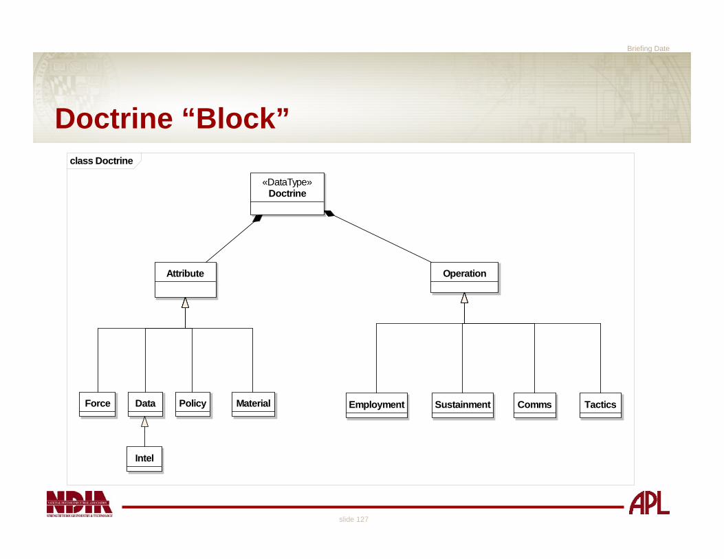
Doctrine “Block”class Doctrine
Intel
Data TacticsCommsPolicy Sustainment
«DataType»Doctrine
OperationAttribute
EmploymentMaterialForce

Briefing Date
slide 128
FSA: Materiel SolutionsAnalysis of Materiel Approaches (AMA)
Assess potential materiel solutions to FNA capability gapso Performanceo Costo Risk
Some similarity to the Analysis of Alternatives (AoA)o Less rigorouso Less specific
Briefing Date
slide 129
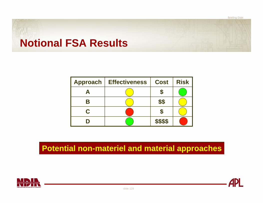
Notional FSA Results
$$$$D$C$$B$A
RiskCostEffectivenessApproach
Potential non-materiel and material approaches

Briefing Date
slide 130
FSA Artifacts
Final Architecture Modelo “To-Be” modelo Material elements that perform functional operations
that provide capability– Measurable Results of Value
JCIDS Documento ICD for Pre-Milestone Ao CDD and CPD for every capability upgradeConcept of Operations (CONOPS)

Briefing Date
slide 131
Concept of Operations Document
The “CONOPS” is not a required JCIDS artifact, howevero CONOPS document is a critical interface between the
operational and the engineering communitieso Provides potential developers the framework on how
the capability will be applied in the operational environment
Services may require some form of CONOPSo USAF Enabling Concept

Briefing Date
slide 132
FSA TBDA “To-Be” Systemclass TBDA FSA
«System»TBDA
«MOE»- Non-Material Contributors 1..N:
+ Develop the TBDA Surveillance Mission()+ Transport the TBDA()+ Collect, Process and Assess Surveillance Information()+ Disseminate the TBDA Information()+ Support and Sustain the TBDA()«Subsystem»
TBDA Air Vehicle
«MOE»- Time of Flight: = > Three Hours- Range for Coverage: = > 300 KM- Range of Coverage for Comm: = > 400 KM- Area of Coverage: = > 62,500 KM
+ Execute Vehcle Transport Functions()
«Subsystem»TBDA Ground Control Station
+ Develop the TBDA Surveillance Mission()+ Control TBDA Air Vehicle()+ Process TBDA Information()
«Subsystem»TBDA Sensor System
«MOE»- Field of View (Staring): = +- 30 Degrees- Sensor Field of Regard: = +- 60 Degrees- Sensor Range Minimum: = 5KM- Sensor Range Maximum: = 30 KM- Minimum RCS: = 2 Square Meters- Range of Target Speeds: = 5 to 75 MPH
+ Capture Surveillance Information()
«Subsystem»TBDA Comm System
«MOE»- Data Link Effective Range: = 400 KM- Bandwidth/ Wave Form: = Link-16/ UHF-VMF- Data Transfer Rate:
+ Disseminate TBDA Information()+ Interface with GIG()
TBDA Sustainment Element
«MOE»- Launch and Landing Range: int = <= 100 Meters- Set Up Time: = <= 30 Minutes- Mean Maintenance Time: = < 2 hours when ...- MTBMA: = > 48 Flight Hours
+ Support and Sustain the TBDA () : void
Vehicle
(from Vehicle)
Sensor
(from Sensors)
Comm & Data Link
(from Communications)
Logistics and Supportability
(from Logistics and Supportability)
«DataType»Capability Gap List
- Capability Gap 1..N:
«trace»
«trace»
«trace»
«trace»
«trace»
«trace»

Briefing Date
slide 133
TBDA Development Optionsclass TBDA Options
«System»TBDA
«MOE»- Non-Material Contributors 1..N:
+ Develop the TBDA Surveillance Mission()+ Transport the TBDA()+ Collect, Process and Assess Surveillance Information()+ Disseminate the TBDA Information()+ Support and Sustain the TBDA()
«System»Scan Eagle
«Subsystem»TBDA System Enhancements
«System»New TBDA
Development
Emphasis is still the Capability with options to
pursue during concept evaluation and risk reduction
phase (Post MS A)

Briefing Date
slide 134
JCIDS Process
*CJCSM 3170.01B
Joint Operations Concepts
Joint Operating ConceptsJoint Functional ConceptsJoint Integrating Concepts
Functional Area Analysis
FunctionalNeeds
Analysis
DOTLPFAnalysis
(Non-materielApproaches)
Ideas forMateriel
Approaches
Analysis ofMateriel/
Non-materielApproaches
Alternative NAlternative 2
Alternative 1JCD
CPD
CDD
ICD
DCR
IntegratedArchitectures
PostIndependent
Analysis
Functional Solution Analysis
DOD StrategicGuidance

Briefing Date
slide 135
Post Independent Analysis
Final independent review of FAA, FNA, and FSAo Not the same people who conducted the analyseso Ensure…
– Analyses were thorough– Potential solutions are reasonable– Potential solution set is complete

Briefing Date
slide 136
FAA, FNA, FSA, PIA Output
There is no capability gap
Capability gap can be addressed by change to:o DOT_LPF - Doctrine, organization, training,
leadership/education, personnel, and facilitieso DCR - DOTLPF Change Request
A materiel solution is requiredo Initial Capabilities Document (ICD)
Briefing Date
slide 137
Conclusion on Functional Analyses
FAA, FNA, FSA, and PIA are import steps to identify, assess, and prioritize joint military capability needso FAA – required capabilitieso FNA – gaps in planned capabilitieso FSA – potential solutions
Conducted through a combination of quantitative and qualitative analyses
Involve all stakeholders in the process

Briefing Date
slide 138
Tutorial Wrap-up
JCIDS is an engineering intensive process!The Systems Engineering Method is appropriate for guiding the JCIDS analyses in every phase of the capability/ system life cycleo Ensures traceability system functionality back to
requirementsModel Driven SE enables the JCIDS Team to fully understand what they are doingo SE Models provide the basis for the system’s architecture and
all architectural viewso SE Model is a living entity that transitions from JCIDS Team
to Development Team– Today’s “To-Be” model becomes tomorrow’s “As-Is”

Briefing Date
slide 139
Tutorial Wrap-up
JCIDS Functional Analyses, including AMA and PIA, are essential SE functionso Each phase, from FAA through FSA, better quantifies
the degree of “materialization”– Including non-materiel capability contributors
OMG SysML is most appropriate for modeling capabilities from early conceptualization to system designo Either OO or Traditional Structured methods
Good SE Effective JCIDS


