SANDIA REPORT SAND2009-7836 Unlimited Release Printed October 2009 Systems Engineering Management Plans Tamara S. Rodriguez Prepared by Sandia National Laboratories Albuquerque, New Mexico 87185 and Livermore, California 94550 Sandia is a multiprogram laboratory operated by Sandia Corporation, a Lockheed Martin Company, for the United States Department of Energy’s National Nuclear Security Administration under Contract DE-AC04-94AL85000. Approved for public release; further dissemination unlimited.
Transcript
SANDIA REPORT SAND2009-7836 Unlimited Release Printed October 2009
Systems Engineering Management Plans Tamara S. Rodriguez Prepared by Sandia National Laboratories Albuquerque, New Mexico 87185 and Livermore, California 94550
Sandia is a multiprogram laboratory operated by Sandia Corporation, a Lockheed Martin Company, for the United States Department of Energy’s National Nuclear Security Administration under Contract DE-AC04-94AL85000.
Approved for public release; further dissemination unlimited.
2
Issued by Sandia National Laboratories, operated for the United States Department of Energy by Sandia Corporation. NOTICE: This report was prepared as an account of work sponsored by an agency of the United States Government. Neither the United States Government, nor any agency thereof, nor any of their employees, nor any of their contractors, subcontractors, or their employees, make any warranty, express or implied, or assume any legal liability or responsibility for the accuracy, completeness, or usefulness of any information, apparatus, product, or process disclosed, or represent that its use would not infringe privately owned rights. Reference herein to any specific commercial product, process, or service by trade name, trademark, manufacturer, or otherwise, does not necessarily constitute or imply its endorsement, recommendation, or favoring by the United States Government, any agency thereof, or any of their contractors or subcontractors. The views and opinions expressed herein do not necessarily state or reflect those of the United States Government, any agency thereof, or any of their contractors. Printed in the United States of America. This report has been reproduced directly from the best available copy. Available to DOE and DOE contractors from U.S. Department of Energy Office of Scientific and Technical Information P.O. Box 62 Oak Ridge, TN 37831 Telephone: (865) 576-8401 Facsimile: (865) 576-5728 E-Mail: [email protected] Online ordering: http://www.osti.gov/bridge Available to the public from U.S. Department of Commerce National Technical Information Service 5285 Port Royal Rd. Springfield, VA 22161 Telephone: (800) 553-6847 Facsimile: (703) 605-6900 E-Mail: [email protected] Online order: http://www.ntis.gov/help/ordermethods.asp?loc=7-4-0#online
3
SAND2009-7836 Unlimited Release
Printed October 2009
Systems Engineering Management Plans
Tamara S. Rodriguez Responsive Neutron Generator Product Deployment
Sandia National Laboratories P.O. Box 5800
Albuquerque, New Mexico 87185-MS0877
Abstract The Systems Engineering Management Plan (SEMP) is a comprehensive and effective tool used to assist in the management of systems engineering efforts. It is intended to guide the work of all those involved in the project. The SEMP is comprised of three main sections: technical project planning and control, systems engineering process, and engineering specialty integration. The contents of each section must be tailored to the specific effort. A model outline and example SEMP are provided. The target audience is those who are familiar with the systems engineering approach and who have an interest in employing the SEMP as a tool for systems management. The goal of this document is to provide the reader with an appreciation for the use and importance of the SEMP, as well as provide a framework that can be used to create the management plan.
4
Acknowledgments The author would like to acknowledge the W.P. Carey School of Business at Arizona State University for creating the Technology, Science, and Engineering MBA program. The program incorporates the opportunity to earn a certificate in Systems Engineering. The author would also like to thank Dr. Dan Shunk who created and instituted the certificate program and guided her through the creation of a Systems Engineering Management Plan. He has been, and will continue to be, at the forefront of developing the field of Systems Engineering. The author would also like to acknowledge Bill Stubblefield and Tran Lai for their valuable feedback and input.
Distribution ................................................................................................................................... 29
6
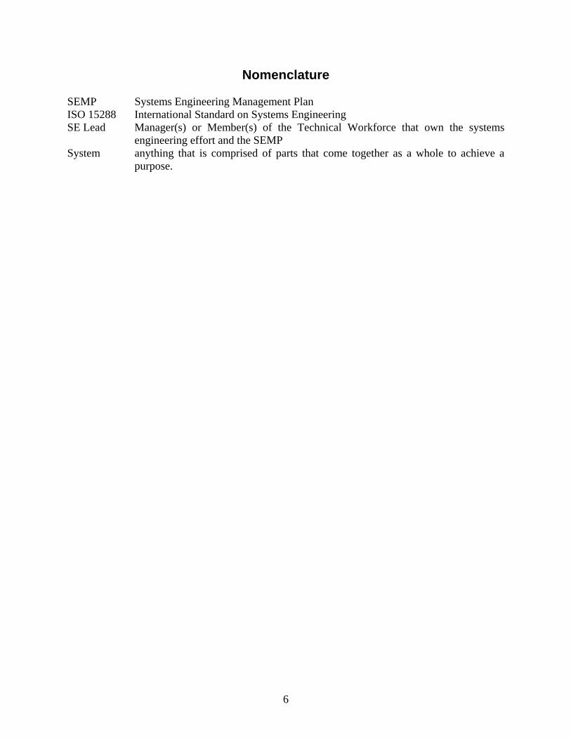
Nomenclature SEMP Systems Engineering Management Plan ISO 15288 International Standard on Systems Engineering SE Lead Manager(s) or Member(s) of the Technical Workforce that own the systems
engineering effort and the SEMP System anything that is comprised of parts that come together as a whole to achieve a
purpose.
7
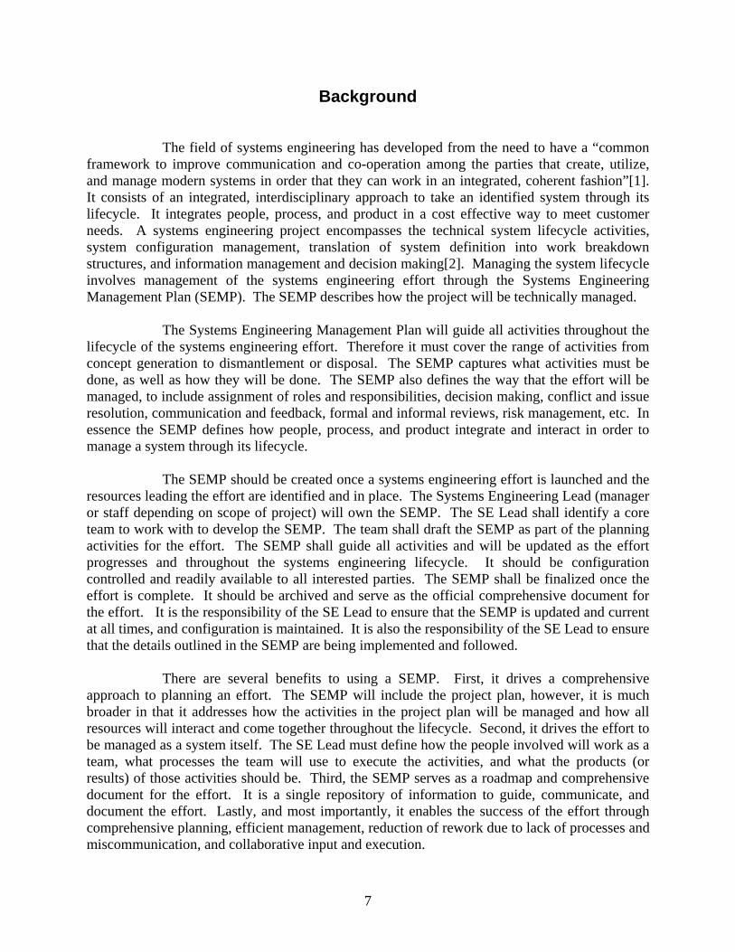
Background The field of systems engineering has developed from the need to have a “common framework to improve communication and co-operation among the parties that create, utilize, and manage modern systems in order that they can work in an integrated, coherent fashion”[1]. It consists of an integrated, interdisciplinary approach to take an identified system through its lifecycle. It integrates people, process, and product in a cost effective way to meet customer needs. A systems engineering project encompasses the technical system lifecycle activities, system configuration management, translation of system definition into work breakdown structures, and information management and decision making[2]. Managing the system lifecycle involves management of the systems engineering effort through the Systems Engineering Management Plan (SEMP). The SEMP describes how the project will be technically managed. The Systems Engineering Management Plan will guide all activities throughout the lifecycle of the systems engineering effort. Therefore it must cover the range of activities from concept generation to dismantlement or disposal. The SEMP captures what activities must be done, as well as how they will be done. The SEMP also defines the way that the effort will be managed, to include assignment of roles and responsibilities, decision making, conflict and issue resolution, communication and feedback, formal and informal reviews, risk management, etc. In essence the SEMP defines how people, process, and product integrate and interact in order to manage a system through its lifecycle. The SEMP should be created once a systems engineering effort is launched and the resources leading the effort are identified and in place. The Systems Engineering Lead (manager or staff depending on scope of project) will own the SEMP. The SE Lead shall identify a core team to work with to develop the SEMP. The team shall draft the SEMP as part of the planning activities for the effort. The SEMP shall guide all activities and will be updated as the effort progresses and throughout the systems engineering lifecycle. It should be configuration controlled and readily available to all interested parties. The SEMP shall be finalized once the effort is complete. It should be archived and serve as the official comprehensive document for the effort. It is the responsibility of the SE Lead to ensure that the SEMP is updated and current at all times, and configuration is maintained. It is also the responsibility of the SE Lead to ensure that the details outlined in the SEMP are being implemented and followed. There are several benefits to using a SEMP. First, it drives a comprehensive approach to planning an effort. The SEMP will include the project plan, however, it is much broader in that it addresses how the activities in the project plan will be managed and how all resources will interact and come together throughout the lifecycle. Second, it drives the effort to be managed as a system itself. The SE Lead must define how the people involved will work as a team, what processes the team will use to execute the activities, and what the products (or results) of those activities should be. Third, the SEMP serves as a roadmap and comprehensive document for the effort. It is a single repository of information to guide, communicate, and document the effort. Lastly, and most importantly, it enables the success of the effort through comprehensive planning, efficient management, reduction of rework due to lack of processes and miscommunication, and collaborative input and execution.
8
9
SEMP Outline The Systems Engineering Management Plan must cover three core areas at a minimum: I. Technical Project Planning and Control
This section should include details of the project and how it will be managed: scope, roles and responsibilities, schedule/project plan, configuration control, issue management and decision making, project reviews, guiding processes and constraints, measurements of success, verification and validation, etc.
II. Systems Engineering Process This section should include details of the processes used to guide the activities during each phase of the system lifecycle. The entire lifecycle of the system, from concept to disposal, should be identified and defined.
III. Engineering Specialty Integration This section should include details of how the efforts of engineering specialties will be used and integrated with the overall activities of the systems engineering effort. Engineering specialties include: human engineering, quality assurance, transportation, sustainability, safety, etc.
Each area shall include details of the “whats” as well as the “hows”. The SEMP is not intended to repeat the full contents of other technical and administrative documents generated or used in the systems engineering effort. It is intended to be used in the management of the effort and should include high level technical details and overviews while referencing documents housing the finer details. It should guide the SE Lead and team through the project and the system lifecycle. The outline below can be used as a guide. The sections can be tailored to include aspects unique and relevant to the management of the effort at hand. Various other examples can be readily found through a simple search of the World Wide Web.
SEMP Example Outline
1.0 INTRODUCTION
1.1 Overview
Describe the purpose and scope of the SEMP.
1.2 System Description
At a high level, describe the system to be created, to include the entire system
lifecycle from concept to dismantlement/retirement.
10
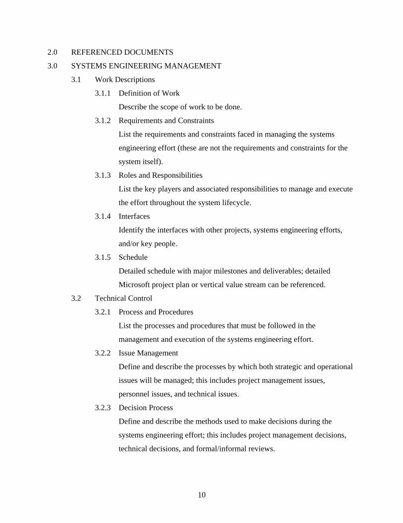
2.0 REFERENCED DOCUMENTS
3.0 SYSTEMS ENGINEERING MANAGEMENT
3.1 Work Descriptions
3.1.1 Definition of Work
Describe the scope of work to be done.
3.1.2 Requirements and Constraints
List the requirements and constraints faced in managing the systems
engineering effort (these are not the requirements and constraints for the
system itself).
3.1.3 Roles and Responsibilities
List the key players and associated responsibilities to manage and execute
the effort throughout the system lifecycle.
3.1.4 Interfaces
Identify the interfaces with other projects, systems engineering efforts,
and/or key people.
3.1.5 Schedule
Detailed schedule with major milestones and deliverables; detailed
Microsoft project plan or vertical value stream can be referenced.
3.2 Technical Control
3.2.1 Process and Procedures
List the processes and procedures that must be followed in the
management and execution of the systems engineering effort.
3.2.2 Issue Management
Define and describe the processes by which both strategic and operational
issues will be managed; this includes project management issues,
personnel issues, and technical issues.
3.2.3 Decision Process
Define and describe the methods used to make decisions during the
systems engineering effort; this includes project management decisions,
technical decisions, and formal/informal reviews.
11
3.2.4 Configuration Control
Define what needs to be configuration controlled and how it will be
controlled (this includes the SEMP and key documents created during the
systems engineering effort).
3.2.5 Training
Define any training required for individuals involved in the effort, to
include training on the systems engineering process.
3.3 Performance Control
3.3.1 Program Assurance
Describe how performance will be monitored and how deviations will be
handled.
3.3.2 Technical Performance Measurement
Define the measures of performance to include what, how, and when.
3.3.3 Risk Management
Describe the process used to manage risk, both project and system.
3.4 Program and Design Reviews
3.4.1 Review Process
Describe the formal and informal review processes that will be used in the
project to include purpose, format, and frequency.
3.4.2 Review Schedule
4.0 SYSTEMS ENGINEERING PROCESS
Describe the processes, approaches, and plans to be used in each phase listed below. The
description should include what and how. The results of each phase may be included.
4.1 System Requirements
4.2 Conceptual and Detail Design
4.3 Development
4.4 Testing
4.5 Evaluation and Decision
4.6 System Verification and Validation
12
4.7 Maintenance/Sustainment
4.8 Disposal/Dismantlement
5.0 ENGINEERING SPECIALTY INTEGRATION
List the applicable engineering specialties that will be included in the systems
engineering effort. For each area describe what activities will be integrated and how.
5.1 Continuous Improvement
5.2 Safety
5.3 Security
5.4 Environment and Health
5.5 Standardization
5.6 Sustainability
5.7 System/Cost Effectiveness
5.8 Assessment
13
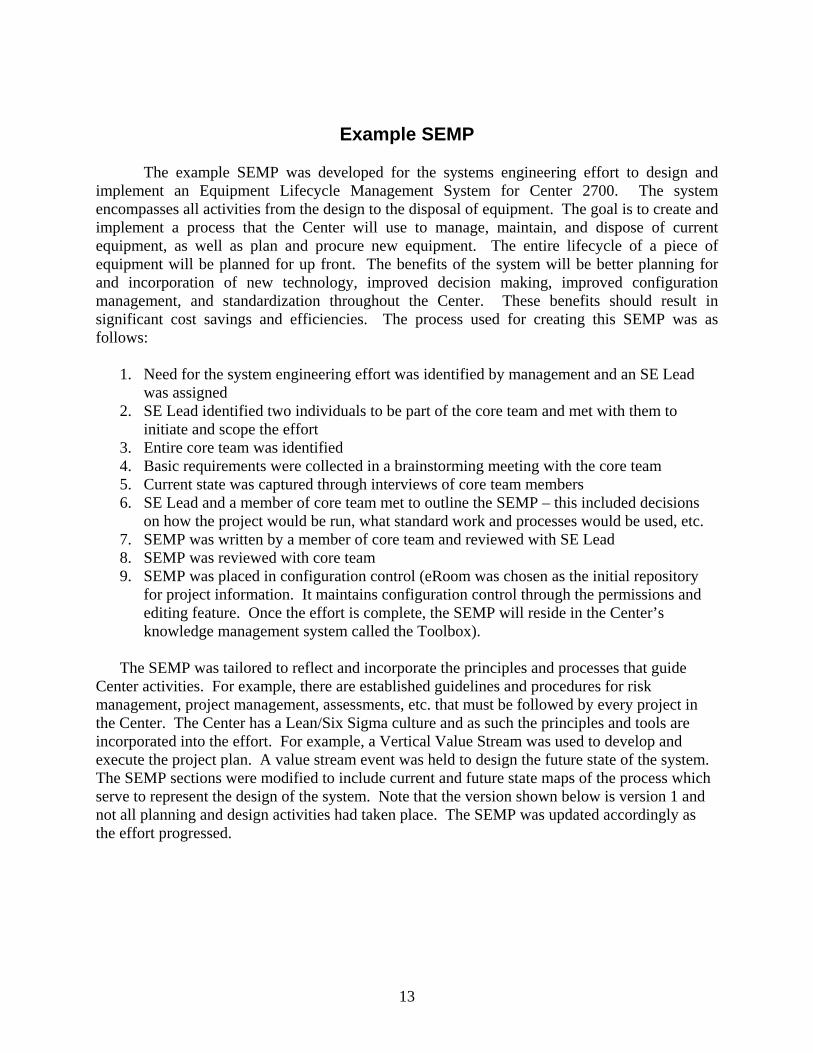
Example SEMP The example SEMP was developed for the systems engineering effort to design and implement an Equipment Lifecycle Management System for Center 2700. The system encompasses all activities from the design to the disposal of equipment. The goal is to create and implement a process that the Center will use to manage, maintain, and dispose of current equipment, as well as plan and procure new equipment. The entire lifecycle of a piece of equipment will be planned for up front. The benefits of the system will be better planning for and incorporation of new technology, improved decision making, improved configuration management, and standardization throughout the Center. These benefits should result in significant cost savings and efficiencies. The process used for creating this SEMP was as follows:
1. Need for the system engineering effort was identified by management and an SE Lead was assigned
2. SE Lead identified two individuals to be part of the core team and met with them to initiate and scope the effort
3. Entire core team was identified 4. Basic requirements were collected in a brainstorming meeting with the core team 5. Current state was captured through interviews of core team members 6. SE Lead and a member of core team met to outline the SEMP – this included decisions
on how the project would be run, what standard work and processes would be used, etc. 7. SEMP was written by a member of core team and reviewed with SE Lead 8. SEMP was reviewed with core team 9. SEMP was placed in configuration control (eRoom was chosen as the initial repository
for project information. It maintains configuration control through the permissions and editing feature. Once the effort is complete, the SEMP will reside in the Center’s knowledge management system called the Toolbox).
The SEMP was tailored to reflect and incorporate the principles and processes that guide
Center activities. For example, there are established guidelines and procedures for risk management, project management, assessments, etc. that must be followed by every project in the Center. The Center has a Lean/Six Sigma culture and as such the principles and tools are incorporated into the effort. For example, a Vertical Value Stream was used to develop and execute the project plan. A value stream event was held to design the future state of the system. The SEMP sections were modified to include current and future state maps of the process which serve to represent the design of the system. Note that the version shown below is version 1 and not all planning and design activities had taken place. The SEMP was updated accordingly as the effort progressed.
14
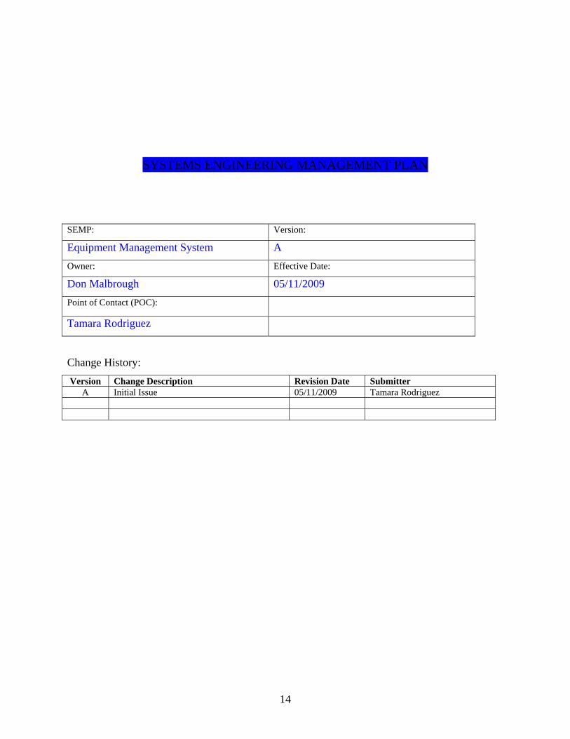
SYSTEMS ENGINEERING MANAGEMENT PLAN SEMP: Version:
Equipment Management System A
Owner: Effective Date:
Don Malbrough 05/11/2009
Point of Contact (POC):
Tamara Rodriguez
Change History:
Version Change Description Revision Date Submitter A Initial Issue 05/11/2009 Tamara Rodriguez
15
1.0 INTRODUCTION
1.1 Overview
This document serves as the plan for the systems engineering effort to develop
and deploy an Equipment Lifecycle Management System in the Center. This plan
will cover all relevant aspects related to the management of the effort. It will
serve as a guide and will be updated appropriately.
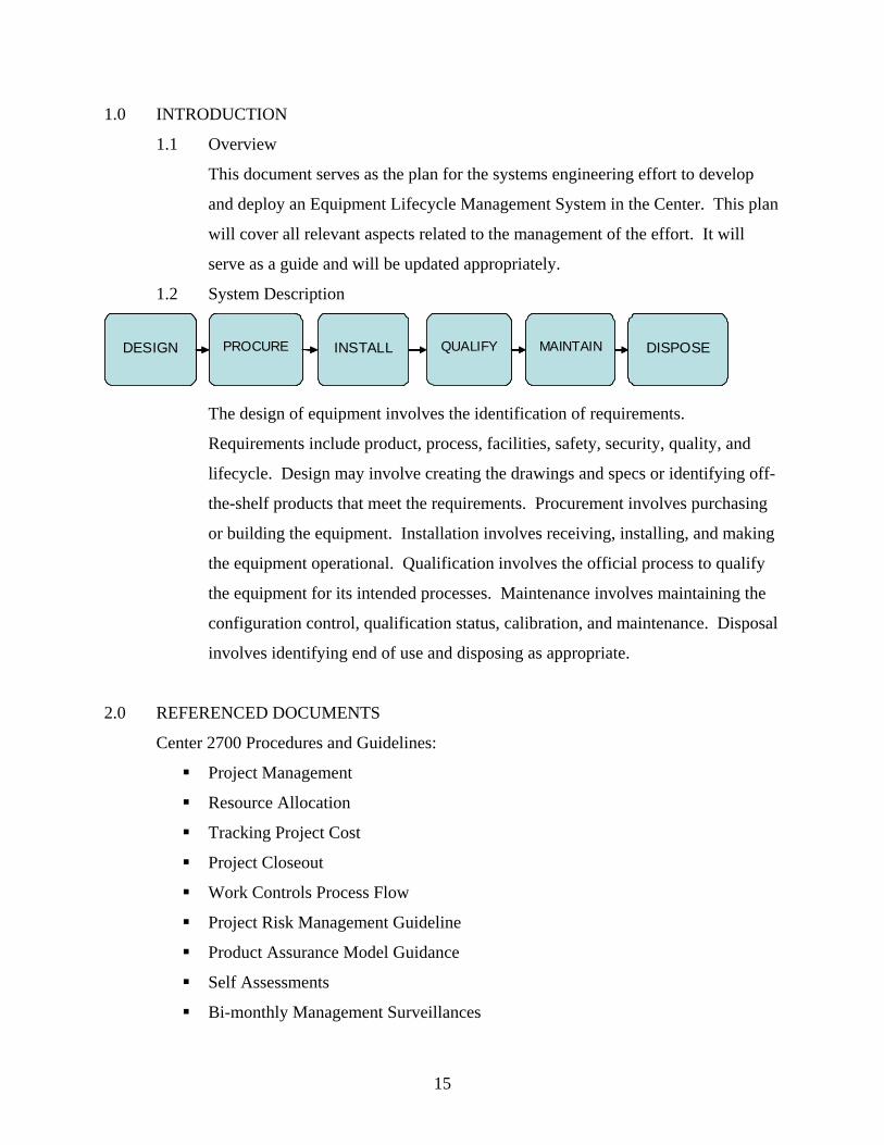
1.2 System Description
The design of equipment involves the identification of requirements.
Requirements include product, process, facilities, safety, security, quality, and
lifecycle. Design may involve creating the drawings and specs or identifying off-
the-shelf products that meet the requirements. Procurement involves purchasing
or building the equipment. Installation involves receiving, installing, and making
the equipment operational. Qualification involves the official process to qualify
the equipment for its intended processes. Maintenance involves maintaining the
configuration control, qualification status, calibration, and maintenance. Disposal
involves identifying end of use and disposing as appropriate.
An Equipment Lifecycle Management System must be created. System
requirements must be defined. The current state must be captured and
analyzed, and a future state must be designed. The action plan for the
future state must be created, to include a risk based, phased approach to
implementation. The system shall be fully implemented by 2011.
3.1.2 Requirements and Constraints
Lean principles shall be followed in the management and execution of the
plan. Center 2700 Procedures, including but not limited to Continuous
Improvement, Risk Based Approach, and Procedure
Creation/Modification will be followed. Center 2700 Guidelines,
including but not limited to the areas of Front Door, Management, and
Production will be followed. All work shall be conducted in a manner
consistent with the values of the organization.
3.1.3 Roles and Responsibilities
Don Malbrough is the manager responsible for this project. The project
team will consist of the following:
Manager/Project Lead – Don Malbrough
Blackbelt – Tamara Rodriguez
Capital Equipment POC – Steve Woodall
Calibration and Maintenance – Cedric Hawkins
ESSH Manager – Sylvia Saltzstein
Analytical Services Manager – Melecita Archuleta
Process Engineering Representative
Team Supervisor Representative
17
Additional team members will be selected for the Configuration
Management Project and the Future State Value Stream. The Blackbelt
will work with the project sponsor/lead to determine the functions that
need to be represented on the teams.
3.1.4 Interfaces
The team shall interface, when appropriate, with the New Product
Development departments and the Applied Science and Technology
Maturation department. The future state shall be designed with
consideration on how it could eventually be applied on a smaller scale to
these functions.
This effort must also coordinate with the following projects occurring in
parallel.
Risk System, P.O.C. Carrie Papp
Total Productive Maintenance (TPM), P.O.C. Dave Goy
Production & Lab Computing Transformation, P.O.C.
Jorge Hernandez
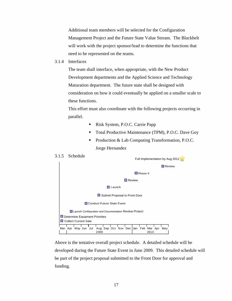
3.1.5 Schedule
Above is the tentative overall project schedule. A detailed schedule will be
developed during the Future State Event in June 2009. This detailed schedule will
be part of the project proposal submitted to the Front Door for approval and
funding.
Review
Phase II
Conduct Future State Event
Submit Proposal to Front Door
Launch Configuration and Documentation Review Project
Determine Equipment Priorities
Collect Current Sate
Launch
Review
Full Implementation by Aug 2011
Mar Apr May Jun Jul Aug Sep Oct Nov Dec Jan Feb Mar Apr May2009 2010
18
3.5 Technical Control
3.5.1 Process and Procedures
The following process outlined in detail in the Center 2700 Guideline for
Project Management will be used to manage this effort.
Submit project proposal to the Front Door
Establish team ground rules and metrics
Create Vertical Value Stream, including key deliverables &
readiness reviews (if applicable), decisions, and milestones with
need dates
Execute the Vertical Value Stream
Conduct Reviews (see Guideline - Tollgate Reviews), ID
inputs/outputs and include same attendees for all reviews
Calculate ROI/ reward (use Tool – Cost Estimation and ROI)
Document project decisions and lessons learned including hazard
controls
Deliver project results
Perform project closeout (see Guideline - Project Closeout)
Place in toolbox as appropriate (see Guideline - Toolbox
Population & Pull)
Note: The processes created for the system will follow lean principles.
They will be documented and maintained in accordance with the Center
2700 Documentation Structure and Guidelines.
3.5.2 Issue Management
Issues with project management or personnel shall be raised to the
Manager leading the project. He shall resolve the issues using standard
Sandia management guidance. Issues that cannot be resolved by the
immediate team will follow the management escalation process.
Technical issues shall be brought to the team. This can be accomplished
by phone, email, or attendance at team meetings. The team will address
and track each issue as part of the project management process. Risk or
19
continuous improvement issues will be resolved through the existing risk
management and continuous improvement processes.
3.5.3 Decision Process
3.5.3.1 Project Team Meetings and Events
The project team will use consensus to make decisions. The team
will discuss and vote on issues during team meetings. Critical
decisions requiring substantive analysis (determined at the
discretion of the team) will be analyzed according to the following
process:
note: Use the Decision Analysis Template as an aid in this process
State the decision
Review required/example objectives
Develop additional objectives
Classify objectives into MUSTs and WANTs
Weight the WANTs
Generate alternatives/options
Screen alternatives through the MUSTs
Compare alternatives through the WANTs
Evaluate specific risks
Make decision
3.2.3.2 Tollgate Reviews
Consensus will be used for all decisions made at the formal tollgate
reviews. Voting rights will be determined and assigned prior to the
review. Voting criteria and information will be sent out prior, and voting
members will have a chance to ask questions of the project team
beforehand via email or phone. A typical decision made at tollgate
reviews is a go, no-go decision to move on to the next phase of the project.
3.5.4 Configuration Control
A project folder shall be created in eRoom for the project team. All
documents created shall be placed in this folder and the configuration
control mechanism within eRoom shall be used. It is the responsibility of
20
the Project Lead to ensure eRoom is being used properly by the team. All
documentation determined relevant at the end of the project will be
archived as part of the Project Closeout procedures. Any Center
Procedures and Guidelines created shall be stored in Web FileShare and
be controlled through the established process.
The Center Procedures and Guidelines are official documents that will
guide work and define the equipment management process. These
documents must be configuration controlled. The Project Lead will be the
owner of the documents. A change to the process will be managed in the
following way:
Opportunity for improvement identified by a staff member and
communicated to the project lead.
Project lead assembles the appropriate team members to review the
improvement opportunity and make a go, no-go decision.
If the decision is go, the team will assess the impact of the change
and plan the implementation.
All affected process documentation will be checked out of Web
FileShare, updated as appropriate, routed for approval, and
checked back in as a new version with effectivity specified.
The system will be updated to reflect the changes.
Staff will be notified of the changes and training will occur if
necessary.
3.6 Performance Control
3.6.1 Program Assurance
Metrics shall be established to measure the effectiveness of the system.
The metrics shall cover, at a minimum, the areas of quality, cost, schedule,
and performance to requirements. Metrics will be identified in the Future
State Event. They will be reviewed on a quarterly basis at the Strategic
Management Review. Metrics are indicated with green, yellow, and red
indicators. An action plan shall be put in place for any metrics that are
21
red. It will be up to the team establishing metrics to establish criteria for
green, yellow, and red indicators.
The system will be assessed yearly as part of the Center 2700 assessment
process. The process is detailed in the Bi-monthly Management
Surveillances Guideline. The assessment will be designed to determine if
the system is meeting requirements. The assessment will be scheduled in
Laboratory Enterprise Self Assessment tool or LESA. The responsible
manager or delegate shall plan and execute the assessment. The manager
documents findings, observations, corrective actions, and note worthy
practices in LESA and reports them to the management team. Any
resulting improvement action items are assigned, reported on, and tracked
by the manager.
3.6.2 Risk Management
Risks will be identified and managed throughout the project. The
following process will be used to manage risks:
Identify potential risk events
Analyze each risk event to determine its likelihood of occurrence and consequence to the project
Prioritize by computing the risk level as a function of likelihood and consequence, and ranking
Plan mitigations for each risk
Execute the risk mitigations
Monitor risks and mitigations to detect changes to their likelihood or consequence
Evaluate the effectiveness of the risk management plan
Document risks, mitigation plans and their effectiveness
22
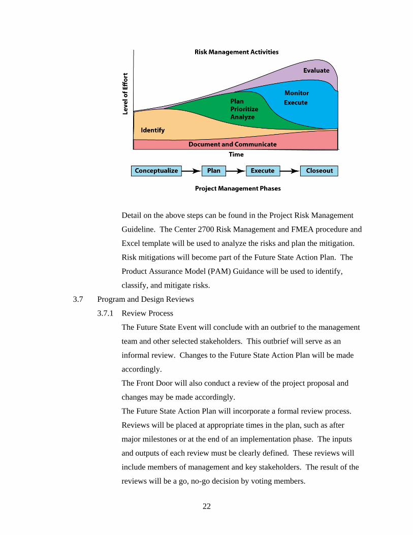
Detail on the above steps can be found in the Project Risk Management
Guideline. The Center 2700 Risk Management and FMEA procedure and
Excel template will be used to analyze the risks and plan the mitigation.
Risk mitigations will become part of the Future State Action Plan. The
Product Assurance Model (PAM) Guidance will be used to identify,
classify, and mitigate risks.
3.7 Program and Design Reviews
3.7.1 Review Process
The Future State Event will conclude with an outbrief to the management
team and other selected stakeholders. This outbrief will serve as an
informal review. Changes to the Future State Action Plan will be made
accordingly.
The Front Door will also conduct a review of the project proposal and
changes may be made accordingly.
The Future State Action Plan will incorporate a formal review process.
Reviews will be placed at appropriate times in the plan, such as after
major milestones or at the end of an implementation phase. The inputs
and outputs of each review must be clearly defined. These reviews will
include members of management and key stakeholders. The result of the
reviews will be a go, no-go decision by voting members.
23
The project team will conduct bi-weekly informal status reviews.
3.7.2 Review Schedule
TBD: The Review Schedule will be determined in the Future State Event
to be tentatively held the week of June 15th 2009.
4.0 SYSTEM ENGINEERING PROCESS
4.1 System Requirements
The Equipment Lifecycle Management System must satisfy the following set of
requirements:
– Effectively identify and manage equipment requirements
– Maintain configuration of equipment and manage changes
– Include an effective document management system
– Define ownership and roles and responsibilities
– Include a decision making process
– Include a risk management process
– Link to calibration and maintenance department
– Link to ESSH department
– Define the entire equipment lifecycle process (purchase to disposal)
– Define the use of outside resources (internal or external to SNL)
24
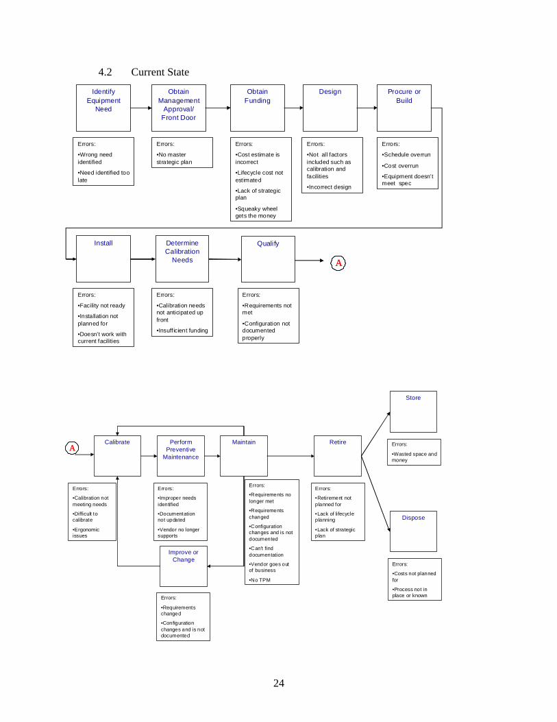
4.2 Current State
Identify Equipment
Need
Obtain Management
Approval/ Front Door
Obtain Funding
Design
Determine Calibration
Needs
Install Qualify
Procure or Build
Errors:
•Wrong need identified
•Need identified too late
Errors:
•No master strategic plan
Errors:
•Cost estimate is incorrect
•Lifecycle cost not estimated
•Lack of strategic plan
•Squeaky wheel gets the money
Errors:
•Not all factors included such as calibration and facilities
•Incorrect design
Errors:
•Schedule overrun
•Cost overrun
•Equipment doesn’t meet spec
Errors:
•Facility not ready
•Installation not planned for
•Doesn’t work with current facilities
Errors:
•Calibration needs not anticipated up front
•Insuff icient funding
Errors:
•Requirements not met
•Configuration not documented properly
AA
Calibrate Perform Preventive
Maintenance
Maintain Retire
Store
Improve or Change
Dispose
Errors:
•Calibration not meeting needs
•Difficult to calibrate
•Ergonomic issues
Errors:
•Improper needs identified
•Documentation not updated
•Vendor no longer supports
Errors:
•Requirements no longer met
•Requirements changed
•Configuration changes and is not documented
•Can’t find documentation
•Vendor goes out of business
•No TPM
Errors:
•Requirements changed
•Configuration changes and is not documented
Errors:
•Retirement not planned for
•Lack of lifecycle planning
•Lack of strategic plan
Errors:
•Wasted space and money
Errors:
•Costs not planned for
•Process not in place or known
AA
25
4.3 Future State Design
The Future State will be developed during the Future State Event. However, it
shall include the following identified elements:
Categorization system for equipment (include criteria to categorize and
level of rigor required for each category)
Mistake proofing
Robust, collaborative planning process to include cost estimation, safety
and security evaluation, and lifecycle estimation
4.4 Future State Action Plan
TBD: The Future State Action Plan will be determined in the Future State Event
to be tentatively held the week of June 15th 2009. The Action Plan will be in the
form of a Vertical Value Stream (VVS). The Project Lead will be the owner of
the VVS and shall report progress to the VVS at the monthly Tactical
Management Reviews.
4.5 Equipment Priority List
TBD: The Future State Action Plan shall detail the rollout of the process in
phases based on criticality of the equipment. A priority list of equipment will be
generated and used to determine the phased approach for implementation into the
new system.
4.6 System Verification and Validation
A review will take place after the pilot and each subsequent implementation
phase. The system configuration will be verified. A baseline of the metrics will
be established. Verification and validation will be conducted prior to each review
such that results can be presented at the review. The system metrics will be
assessed and reviewed at each phase review as well as at the Management
Reviews. The verification and validation results will become part of the project
closeout document.
Periodic reviews of progress to the goals and tracking of the system metrics will
serve as constant validation. The metrics shall be re-baselined after any major
changes. The metrics will be reviewed as part of the internal assessment
procedures and the Management Reviews.
26
5.0 ENGINEERING SPECIALTY INTEGRATION
5.1 Continuous Improvement
Center 2700 fosters a culture of continuous improvement. It is expected that all
processes will be evaluated for improvements. The Project Lead shall be the
point of contact for improvement opportunities. The opportunities may be
identified through employees using the system, formal and informal assessments,
and management review. The Project Lead shall assemble the appropriate team to
discuss improvement opportunities and determine how to proceed. Once an
improvement is made, all appropriate documentation shall be updated, the change
shall be communicated to all necessary employees with training if applicable, and
metrics shall be tracked to validate the improvement.
5.2 Safety
ESSH shall be integrated into the Equipment Management System. A
representative from ESSH shall be included in the planning and decision making
for equipment. The representative will be responsible to ensure that safety,
facility, ergonomic, and environmental issues are addressed.
5.3 Security
Physical and cyber-security issues shall be identified and addressed during the
planning process. A representative from the ESSH and IT departments shall be
included to assess potential issues and participate in decision making regarding
those issues.
5.4 Standardization
The system shall incorporate standardization where appropriate. At a minimum
the process shall be defined and institutionalized in the form of a Center 2700
Procedure. Employees shall be trained to the procedure. One page recipe cards
shall be used. TPM shall incorporate standard markings, identifications, and
templates. Equipment documentation shall follow a standard guideline.
5.5 System/Cost Effectiveness
The cost of system implementation shall be tracked by the Project Lead. The
costs to manage the system shall be tracked as well as equipment purchase and
27
management costs. Savings in the form of reduced costs or cost avoidances
during the equipment lifecycle shall be tracked. The costs and savings shall be
compared and reviewed on a yearly basis. Improvements to the system may be
identified. The Cost Estimation and ROI spreadsheet shall be used to capture this
information.
5.6 Assessment
This system will become part of the Center 2700 Management System. As such,
it will be another element that will be assessed through the existing self
assessment process. This system may also be included in external (to the Center)
assessments such as: ISO assessments, formal audits performed by customers and
outside agencies, and internal assessment performed by Center 12000, Sandia
Quality. External assessments are guided by their own set of specific procedures.
If the Equipment Management System is part of an external assessment, the
Project Lead will follow the appropriate guidelines to review feedback, execute
corrective actions, and update the system.
28
References [1] ISO/IEC 15288, Systems engineering – System life cycle processes, First edition 2002-11-01 [2] NASA Systems Engineering Handbook,SP-610S,1995 [3] SEMP (FM 770-78), g2sebok.incose.org/documents/assets/.../semp fm 770-78.pdf [4] Systems Engineering Management Plan, Honourcode, Inc., Document Outline, September 2003, g2sebok.incose.org/documents/assets/MSS/.../semp_honour.pdf
29
Distribution 1 MS0868 Kathleen McCaughey 2700 1 MS0873 Don Malbrough 2717 1 MS0653 Daniel Roberts 3521 2 MS9018 Central Technical Files 8944 2 MS0899 Technical Library 9536