28
Electrofusion fings Gas, water and wastewater applicaons Systems September 2017

Electrofusion fittingsGas, water and wastewater applications
S y s t e m s
September 2017

Maximum fusion integrity for the longevity of your pipeline
With over 50 years expertise in the innovation, design and manufacture of polyethylene (PE) pipeline systems, Radius Systems have established a proven track record of delivering state-of-the-art pipe and fittings solutions for our customers’ pipeline infrastructure. For decades, PE has been the material of choice for new installations and the rehabilitation of gas and water networks as pipe systems offer a fully welded solution, which is lightweight, easy to install and corrosion free and when correctly designed and installed, PE pipelines will last in excess of 100 years.
A technologically advanced solution
Specifically designed for ease of assembly and to provide optimum efficiency during the welding process, our range of universal black electrofusion fittings offers specifiers and installers a high performance jointing solution for their whole PE pipeline.
Designed for natural and suitable manufactured gases, drinking water and wastewater PE pipelines, our range of electrofusion fittings are made from high strength black PE100, with exposed wire technology offering maximum heat transfer and distribution during the welding process. For ease of installation, our socket fittings are manufactured with insertion stops to ensure the pipe is fully engaged into the fitting during assembly.
Manufactured in our ISO 9001:2015 and OHSAS 18001:2007 accredited facilities, our electrofusion fittings are extensively tested in our dedicated laboratories, providing the assurance of a high performance fitting solution for your pipeline.
Approvals
Our electrofusion fittings are approved to the most stringent national, international or in-house specifications. Some of our fittings have been developed for specific markets or to meet particular customer requirements. For individual fitting approval(s), please contact Radius Systems.
Gas• BS EN 1555-3 - KM 596928• GIS/PL2:4 - KM 538462• DVGW GW 335-B2• MPA Darmstadt - K 1598/12.2014• IIP Certification of Conformity to EN 1555-3
Water and wastewater• BS EN 12201-3 - KM 597648• WRAS approved material• DVGW GW 335-B2• MPA Darmstadt - K 1597/12.2014• IIP Certification of Conformity to EN 12201-3
DV-8601BN0126DV-8601BN0127DV-8611BN0627
2 w: www.radius-systems.com
S y s t e m s

t: +44 (0)1773 811112 e: [email protected] 3
Innovative fitting solutions
Electrofusion fittings maximum operating pressure (MOP) Our electrofusion fittings are tested for use with PE80 and PE100 pipes in a wide range of SDRs, with MOP in accordance with national and international specifications:
•UK gas specification GIS/PL2:4 up to 5.5 bar or 7 bar•European gas specification BS EN 1555-3 up to 10 bar•European water specification BS EN 12201-3 up to 16 bar
Due to our extensive offering, some fittings within our range may have a lower maximum operating pressure than quoted above. For the most up to date pressure ratings, product approval and welding compatibility, please refer to the fitting's packaging or contact Radius Systems for more information.
Exposed wire
Terminal pins
High strength PE material
Profiled body
Insertion stops
Technological and manufacturing know-how
Our extensive industry knowledge in the design and manufacture of electrofusion fittings means that we are continually developing smarter solutions that help bring installation time savings and efficiencies. We work closely with our customers to bring to market innovative and technologically advanced fittings that offer maximum joint integrity, are easy to install and are robust in operation.
Features & Benefits• A range of universal fittings suitable for gas, water and wastewater
applications• Manufactured from high strength polyethylene• Exposed wire technology for maximum heat transfer during the
fusion process• Patented Easigrip® technology for large diameter fittings for ease of
handling during installation• Simultaneous socket fusion for all fittings• Barcode technology - for electrofusion control unit programming
and fitting traceability• Corrosion resistant• End-load bearing jointing system
• Exposed wire technology for optimum heat transfer between the fitting and the pipe during the electrofusion process
• Available with 4.0 (40 Volt) and 5.7 mm (80 Volt) terminal pin connections to suit market requirements
• Manufactured from high strength PE for increased fitting integrity
• Profiled body for optimum material usage
• Welding and traceability barcode technology
4 w: www.radius-systems.com
S y s t e m s
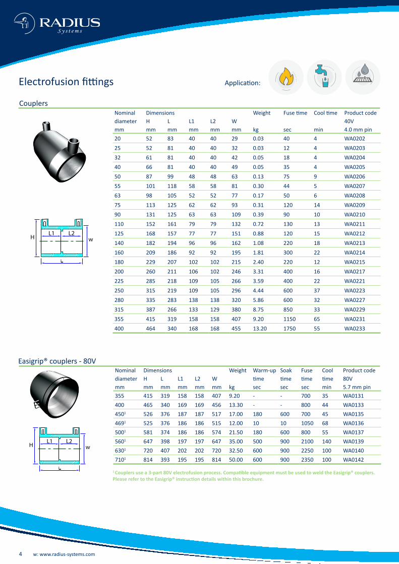
Electrofusion fittings
Couplers
L1 L2wH
Nominal Dimensions Weight Fuse time Cool time Product codediameter H L L1 L2 W 40Vmm mm mm mm mm mm kg sec min 4.0 mm pin20 52 83 40 40 29 0.03 40 4 WA020225 52 81 40 40 32 0.03 12 4 WA020332 61 81 40 40 42 0.05 18 4 WA020440 66 81 40 40 49 0.05 35 4 WA020550 87 99 48 48 63 0.13 75 9 WA020655 101 118 58 58 81 0.30 44 5 WA020763 98 105 52 52 77 0.17 50 6 WA020875 113 125 62 62 93 0.31 120 14 WA020990 131 125 63 63 109 0.39 90 10 WA0210110 152 161 79 79 132 0.72 130 13 WA0211125 168 157 77 77 151 0.88 120 15 WA0212140 182 194 96 96 162 1.08 220 18 WA0213160 209 186 92 92 195 1.81 300 22 WA0214180 229 207 102 102 215 2.40 220 12 WA0215200 260 211 106 102 246 3.31 400 16 WA0217225 285 218 109 105 266 3.59 400 22 WA0221250 315 219 109 105 296 4.44 600 37 WA0223280 335 283 138 138 320 5.86 600 32 WA0227315 387 266 133 129 380 8.75 850 33 WA0229355 415 319 158 158 407 9.20 1150 65 WA0231400 464 340 168 168 455 13.20 1750 55 WA0233
Application:
Easigrip® couplers - 80V
1 Couplers use a 3-part 80V electrofusion process. Compatible equipment must be used to weld the Easigrip® couplers. Please refer to the Easigrip® instruction details within this brochure.
L1 L2wH
Nominal Dimensions Weight Warm-up Soak Fuse Cool Product codediameter H L L1 L2 W time time time time 80Vmm mm mm mm mm mm kg sec sec sec min 5.7 mm pin355 415 319 158 158 407 9.20 - - 700 35 WA0131400 465 340 169 169 456 13.30 - - 800 44 WA01334501 526 376 187 187 517 17.00 180 600 700 45 WA01354691 525 376 186 186 515 12.00 10 10 1050 68 WA01365001 581 374 186 186 574 21.50 180 600 800 55 WA01375601 647 398 197 197 647 35.00 500 900 2100 140 WA01396301 720 407 202 202 720 32.50 600 900 2250 100 WA01407101 814 393 195 195 814 50.00 600 900 2350 100 WA0142
t: +44 (0)1773 811112 e: [email protected] 5
L1 L2
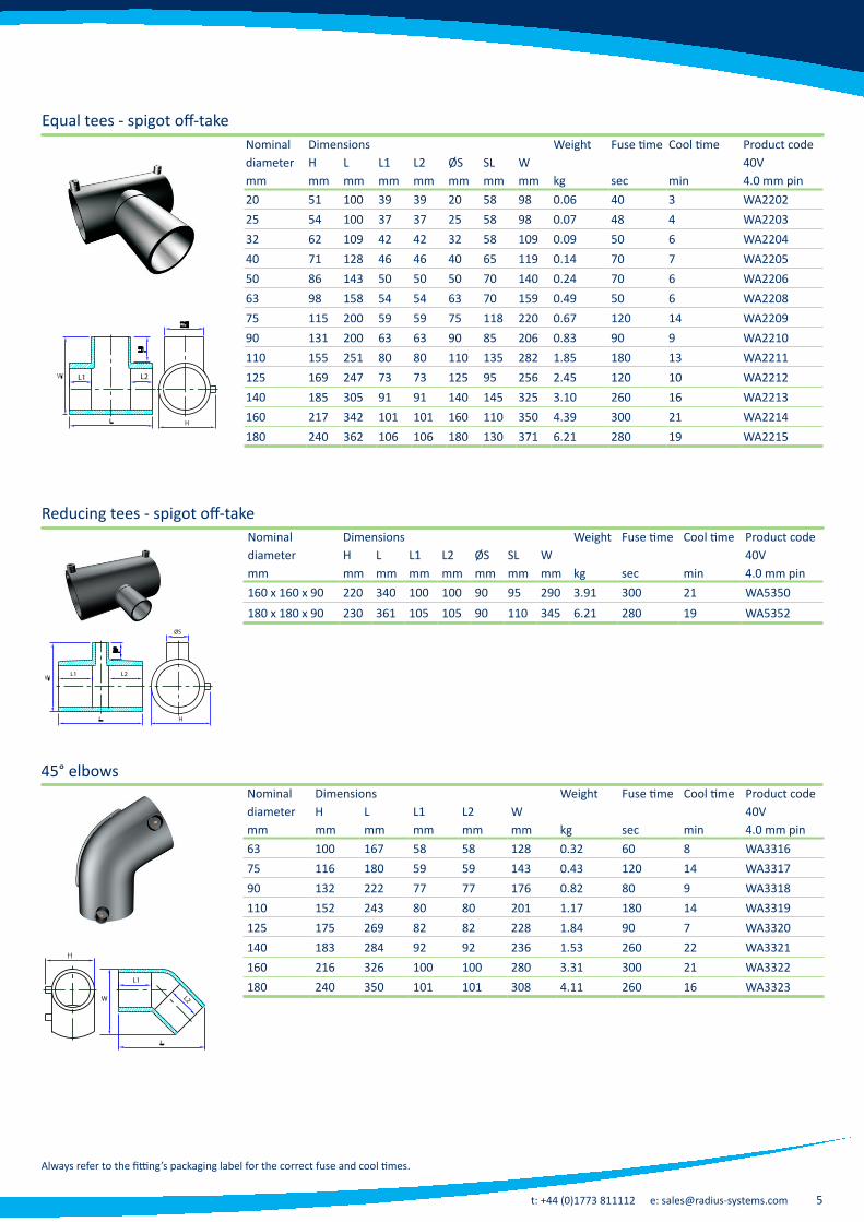
Equal tees - spigot off-take
L1 L2
ØS
Reducing tees - spigot off-take
L2W
L1
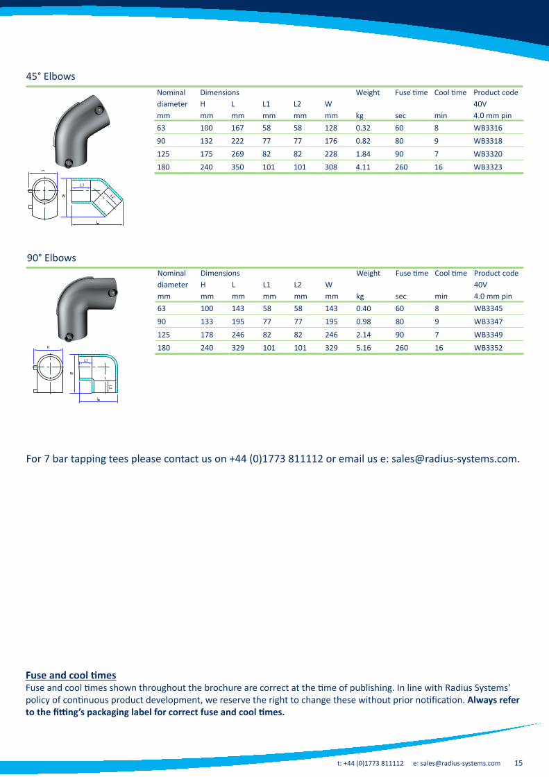
45° elbows
Always refer to the fitting’s packaging label for the correct fuse and cool times.
Nominal Dimensions Weight Fuse time Cool time Product codediameter H L L1 L2 ØS SL W 40Vmm mm mm mm mm mm mm mm kg sec min 4.0 mm pin20 51 100 39 39 20 58 98 0.06 40 3 WA220225 54 100 37 37 25 58 98 0.07 48 4 WA220332 62 109 42 42 32 58 109 0.09 50 6 WA220440 71 128 46 46 40 65 119 0.14 70 7 WA220550 86 143 50 50 50 70 140 0.24 70 6 WA220663 98 158 54 54 63 70 159 0.49 50 6 WA220875 115 200 59 59 75 118 220 0.67 120 14 WA220990 131 200 63 63 90 85 206 0.83 90 9 WA2210110 155 251 80 80 110 135 282 1.85 180 13 WA2211125 169 247 73 73 125 95 256 2.45 120 10 WA2212140 185 305 91 91 140 145 325 3.10 260 16 WA2213160 217 342 101 101 160 110 350 4.39 300 21 WA2214180 240 362 106 106 180 130 371 6.21 280 19 WA2215
Nominal Dimensions Weight Fuse time Cool time Product codediameter H L L1 L2 ØS SL W 40Vmm mm mm mm mm mm mm mm kg sec min 4.0 mm pin 160 x 160 x 90 220 340 100 100 90 95 290 3.91 300 21 WA5350180 x 180 x 90 230 361 105 105 90 110 345 6.21 280 19 WA5352
Nominal Dimensions Weight Fuse time Cool time Product codediameter H L L1 L2 W 40Vmm mm mm mm mm mm kg sec min 4.0 mm pin63 100 167 58 58 128 0.32 60 8 WA331675 116 180 59 59 143 0.43 120 14 WA331790 132 222 77 77 176 0.82 80 9 WA3318110 152 243 80 80 201 1.17 180 14 WA3319125 175 269 82 82 228 1.84 90 7 WA3320140 183 284 92 92 236 1.53 260 22 WA3321160 216 326 100 100 280 3.31 300 21 WA3322180 240 350 101 101 308 4.11 260 16 WA3323
6 w: www.radius-systems.com
S y s t e m s
L1
L2
W
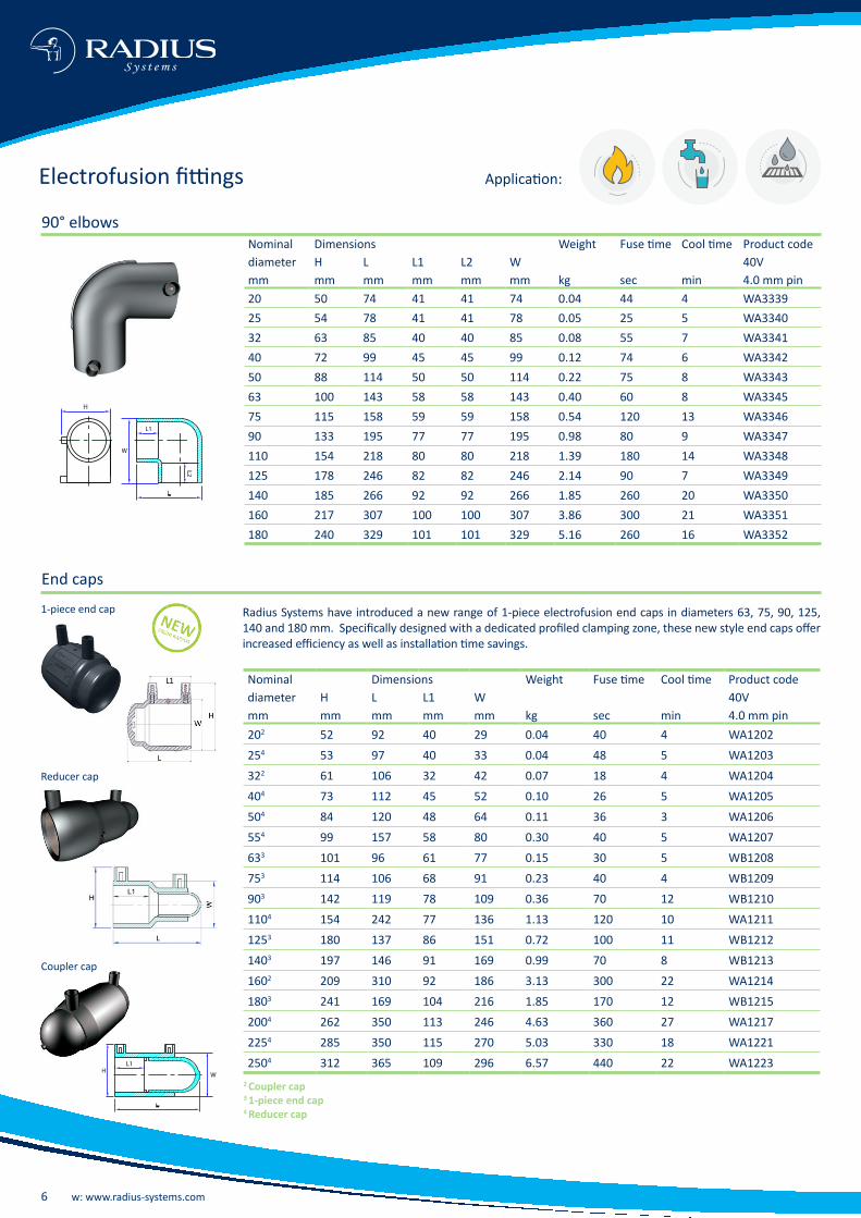
90° elbows
Electrofusion fittings
Nominal Dimensions Weight Fuse time Cool time Product codediameter H L L1 L2 W 40Vmm mm mm mm mm mm kg sec min 4.0 mm pin20 50 74 41 41 74 0.04 44 4 WA333925 54 78 41 41 78 0.05 25 5 WA334032 63 85 40 40 85 0.08 55 7 WA334140 72 99 45 45 99 0.12 74 6 WA334250 88 114 50 50 114 0.22 75 8 WA334363 100 143 58 58 143 0.40 60 8 WA334575 115 158 59 59 158 0.54 120 13 WA334690 133 195 77 77 195 0.98 80 9 WA3347110 154 218 80 80 218 1.39 180 14 WA3348125 178 246 82 82 246 2.14 90 7 WA3349140 185 266 92 92 266 1.85 260 20 WA3350160 217 307 100 100 307 3.86 300 21 WA3351180 240 329 101 101 329 5.16 260 16 WA3352
L1
W
End caps
2 Coupler cap3 1-piece end cap4 Reducer cap
Radius Systems have introduced a new range of 1-piece electrofusion end caps in diameters 63, 75, 90, 125, 140 and 180 mm. Specifically designed with a dedicated profiled clamping zone, these new style end caps offer increased efficiency as well as installation time savings.
1-piece end cap
Reducer cap
Coupler cap
Nominal Dimensions Weight Fuse time Cool time Product codediameter H L L1 W 40Vmm mm mm mm mm kg sec min 4.0 mm pin202 52 92 40 29 0.04 40 4 WA1202254 53 97 40 33 0.04 48 5 WA1203322 61 106 32 42 0.07 18 4 WA1204404 73 112 45 52 0.10 26 5 WA1205504 84 120 48 64 0.11 36 3 WA1206554 99 157 58 80 0.30 40 5 WA1207633 101 96 61 77 0.15 30 5 WB1208753 114 106 68 91 0.23 40 4 WB1209903 142 119 78 109 0.36 70 12 WB12101104 154 242 77 136 1.13 120 10 WA12111253 180 137 86 151 0.72 100 11 WB12121403 197 146 91 169 0.99 70 8 WB12131602 209 310 92 186 3.13 300 22 WA12141803 241 169 104 216 1.85 170 12 WB12152004 262 350 113 246 4.63 360 27 WA12172254 285 350 115 270 5.03 330 18 WA12212504 312 365 109 296 6.57 440 22 WA1223
Application:

t: +44 (0)1773 811112 e: [email protected] 7
Reducers
L1 L2W
Nominal Dimensions Weight Fuse time Cool time Product codediameter H L L1 L2 W 40Vmm mm mm mm mm mm kg sec min 4.0 mm pin20 x 16 49 81 40 40 29 0.04 43 6 WA425220 x ¾" 56 80 39 40 38 0.05 36 3 WA425425 x 20 54 82 43 38 33 0.04 48 5 WA425825 x ¾" 56 80 39 40 38 0.05 30 4 WA425732 x 16 62 82 44 37 43 0.05 15 5 WA425932 x 20 62 89 44 39 43 0.05 36 6 WA426232 x 25 62 89 46 42 43 0.05 40 5 WA426332 x ¾" 63 83 42 40 44 0.05 14 3 WA426132 x 1” 64 83 42 40 45 0.06 60 5 WA426440 x 32 73 89 45 43 52 0.07 26 5 WA426950 x 32 84 98 48 44 64 0.10 36 3 WA427063 x 32 98 117 51 42 77 0.16 55 10 WA427363 x 40 98 116 56 48 78 0.19 85 9 WA427463 x 50 99 117 56 47 78 0.20 90 9 WA427563 x 55 101 117 58 55 81 0.28 40 5 WA427763 x 2” 98 117 57 58 79 0.25 85 12 WA427675 x 63 113 124 60 58 95 0.26 90 14 WA428090 x 63 133 154 80 60 117 0.50 120 10 WA428190 x 75 129 154 77 62 108 0.67 135 18 WA428290 x 3” 134 154 75 77 110 0.60 90 14 WA4283110 x 63 153 188 77 57 136 0.81 100 15 WA4284110 x 90 154 188 86 79 136 0.84 120 10 WA4286125 x 63 177 164 91 63 159 0.96 160 18 WA4287125 x 90 170 180 89 75 155 1.04 120 18 WA4289125 x 110 177 169 85 76 158 1.38 140 12 WA4291125 x 4” 176 164 80 80 156 1.35 140 13 WA4290140 x 125 185 190 92 89 158 1.54 250 35 WA4293160 x 110 218 231 96 85 197 1.84 180 18 WA4294180 x 125 231 200 93 79 216 1.90 280 24 WA4297180 x 140 230 200 90 81 212 1.42 320 22 WA4299180 x 160 236 206 102 97 216 2.10 200 14 WA4302180 x 6” 238 202 99 99 220 2.82 360 31 WA4300200 x 160 262 240 113 106 246 3.22 360 27 WA4303225 x 160 285 240 115 106 270 3.65 330 18 WA4311250 x 180 314 240 117 99 300 4.73 440 22 WA4319315 x 250 390 275 133 110 380 8.26 520 21 WA4332
Always refer to the fitting’s packaging label for the correct fuse and cool times.

8 w: www.radius-systems.com
S y s t e m s
Electrofusion saddle fittings
Tapping tees 32 mm outletNominal Dimensions Weight Fuse time Cool time Product code diameter ØB H HC HS L ØS W 40Vmm mm mm mm mm mm mm mm kg sec min 4.0 mm pin405 20 151 120 71 115 32 62 0.30 40 4 WA633355 20 136 110 71 115 32 67 0.30 55 4 WA633563 & 2” 20 141 110 71 115 32 77 0.30 55 4 WA633275 20 129 110 71 115 32 75 0.30 55 4 WA633790 & 3” 20 130 111 71 115 32 90 0.30 55 4 WA6331110 - 140 & 4” 20 128 115 71 115 32 83 0.30 55 4 WA6330140 - 180 & 6” 20 125 115 71 115 32 88 0.30 55 4 WA6342200 - 250 & 8”6 20 122 115 71 115 32 90 0.30 55 4 WA6348268 - 3556 20 120 115 71 115 32 90 0.30 55 4 WA6359400 - 5606 20 118 115 71 115 32 90 0.30 60 4 WA6363*
Nominal Dimensions Weight Fuse time Cool time Product codediameter ØB H HC HS L ØS W 40Vmm mm mm mm mm mm mm mm kg sec min 4.0 mm pin63 & 2” 34 170 135 106 170 63 77 0.76 55 4 WA646075 34 166 143 106 170 63 100 0.76 55 4 WA646290 & 3” 34 166 135 106 170 63 100 0.76 60 4 WA6463110 - 125 & 4” 34 162 137 106 170 63 105 0.76 70 4 WA6466140 - 155 34 152 137 106 170 63 110 0.76 70 4 WA6467155 - 180 & 6" 34 152 135 106 170 63 110 0.76 70 4 WA64712006 34 146 135 106 170 63 110 0.76 70 4 WA6472213 - 280 & 8"6 34 146 135 106 170 63 110 0.76 75 5 WA6476315 - 3556 34 144 135 106 170 63 110 0.76 80 4 WA6482400 - 4696 34 142 135 106 170 63 110 0.76 75 4 WA6486*500 - 5606 34 139 135 106 170 63 110 0.76 80 5 WA6492*
Our range of saddle fittings have been specifically designed with a universal integral cutter and NBR O-ring seal which are approved for use in gas and water applications. Manufactured from high performance PE100 our saddle fittings are designed with a UnifitTM base to suit a range
5 Fitted with an under-part6 Fitted with a thread follower which must be removed after tapping the main. See guidance within this brochure.ØB = cut hole diameter
*Note: WA6363, WA6486 and WA6492 are not suitable for use with SDR11 pipe. For connection onto SDR11 pipe, please contact RadiusPLUS our live pipeline engineering division on t: 01773 582317 or e: [email protected].
63 mm outlet
of pipe diameters, considerably reducing the need to carry additional stocks of fittings. Quick and easy to install, our saddle fitting solutions are available with a 32 or 63 mm outlet, in diameters 40 mm to 560 mm.
For the MOP of tapping tee products for gas applications, please refer to the packaging label or contact Radius Systems.
For instructions on how to install our tapping tees, please refer to the jointing guidance within this brochure.
Application:

t: +44 (0)1773 811112 e: [email protected] 9
Under-clamp tapping tees 20 mm outlet
25 mm outlet
32 mm outlet
Nominal Dimensions Weight Fuse time Cool time Product code diameter ØB H HC HS L ØS W 40Vmm mm mm mm mm mm mm mm kg sec min 4.0 mm pin40 20 172 135 107 115 20 92 0.60 45 4 WB625150 20 192 135 107 115 20 99 0.60 55 4 WB625263 20 204 135 107 115 20 110 0.64 55 4 WB625475 20 216 135 107 115 20 124 0.67 55 4 WB625590 20 232 135 107 115 20 139 0.71 55 4 WB6256110 20 252 135 107 115 20 159 0.78 55 4 WB6257160 20 302 135 107 115 20 209 0.91 55 4 WB6261
Nominal Dimensions Weight Fuse time Cool time Product code diameter ØB H HC HS L ØS W 40Vmm mm mm mm mm mm mm mm kg sec min 4.0 mm pin40 20 182 135 107 115 25 92 0.60 45 4 WB629250 20 192 135 107 115 25 99 0.60 55 4 WB629363 20 204 135 107 115 25 110 0.64 55 4 WB629575 20 216 135 107 115 25 124 0.67 55 4 WB629690 20 232 135 107 115 25 139 0.71 55 4 WB6297110 20 252 135 107 115 25 159 0.78 55 4 WB6298160 20 302 135 107 115 25 209 0.91 55 4 WB6303
Nominal Dimensions Weight Fuse time Cool time Product code diameter ØB H HC HS L ØS W 40Vmm mm mm mm mm mm mm mm kg sec min 4.0 mm pin40 20 182 135 107 115 32 92 0.60 45 4 WB6333 50 20 192 135 107 115 32 99 0.62 55 4 WB633463 20 204 135 107 115 32 110 0.64 55 4 WB633675 20 216 135 107 115 32 124 0.66 55 4 WB633790 20 232 135 107 115 32 139 0.71 55 4 WB6338110 20 252 135 107 115 32 159 0.75 55 4 WB6339160 20 302 135 107 115 32 209 0.75 55 4 WB6344
ØB = cut hole diameter
For the MOP of tapping tee products for gas applications, please refer to the packaging label or contact Radius Systems.
Always refer to the fitting’s packaging label for the correct fuse and cool times.
10 w: www.radius-systems.com
S y s t e m s
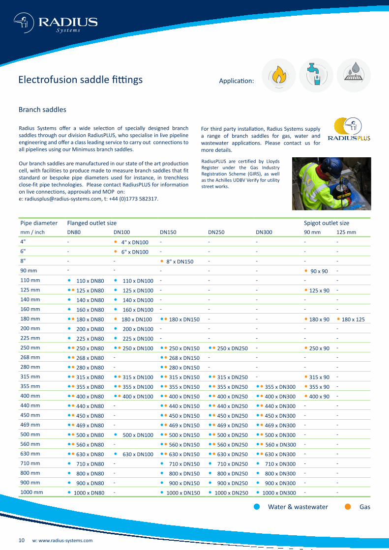
Pipe diameter Flanged outlet size Spigot outlet sizemm / inch DN80 DN100 DN150 DN250 DN300 90 mm 125 mm
4" - • 4" x DN100 - - - - -
6" - • 6" x DN100 - - - - -
8" - - • 8" x DN150 - - - -
90 mm - - - - - • 90 x 90 -
110 mm • 110 x DN80 • 110 x DN100 - - - - -
125 mm •• 125 x DN80 • 125 x DN100 - - - • 125 x 90 -
140 mm • 140 x DN80 • 140 x DN100 - - - - -
160 mm • 160 x DN80 • 160 x DN100 - - - - -
180 mm •• 180 x DN80 • 180 x DN100 •• 180 x DN150 - - • 180 x 90 • 180 x 125200 mm • 200 x DN80 • 200 x DN100 - - - - -
225 mm • 225 x DN80 • 225 x DN100 - - - - -
250 mm •• 250 x DN80 •• 250 x DN100 •• 250 x DN150 •• 250 x DN250 - • 250 x 90 -
268 mm •• 268 x DN80 - •• 268 x DN150 - - - -
280 mm •• 280 x DN80 - •• 280 x DN150 - - - -
315 mm •• 315 x DN80 •• 315 x DN100 •• 315 x DN150 •• 315 x DN250 - • 315 x 90 -
355 mm •• 355 x DN80 •• 355 x DN100 •• 355 x DN150 •• 355 x DN250 •• 355 x DN300 • 355 x 90 -
400 mm •• 400 x DN80 •• 400 x DN100 •• 400 x DN150 •• 400 x DN250 •• 400 x DN300 • 400 x 90 -
440 mm •• 440 x DN80 - •• 440 x DN150 •• 440 x DN250 •• 440 x DN300 - -
450 mm •• 450 x DN80 - •• 450 x DN150 •• 450 x DN250 •• 450 x DN300 - -
469 mm •• 469 x DN80 - •• 469 x DN150 •• 469 x DN250 •• 469 x DN300 - -
500 mm •• 500 x DN80 • 500 x DN100 •• 500 x DN150 •• 500 x DN250 •• 500 x DN300 - -
560 mm •• 560 x DN80 - •• 560 x DN150 •• 560 x DN250 •• 560 x DN300 - -
630 mm •• 630 x DN80 • 630 x DN100 •• 630 x DN150 •• 630 x DN250 •• 630 x DN300 - -
710 mm • 710 x DN80 - • 710 x DN150 • 710 x DN250 • 710 x DN300 - -
800 mm • 800 x DN80 - • 800 x DN150 • 800 x DN250 • 800 x DN300 - -
900 mm • 900 x DN80 - • 900 x DN150 • 900 x DN250 • 900 x DN300 - -
1000 mm • 1000 x DN80 - • 1000 x DN150 • 1000 x DN250 • 1000 x DN300 - -
Branch saddles
Radius Systems offer a wide selection of specially designed branch saddles through our division RadiusPLUS, who specialise in live pipeline engineering and offer a class leading service to carry out connections to all pipelines using our Minimuss branch saddles.
Our branch saddles are manufactured in our state of the art production cell, with facilities to produce made to measure branch saddles that fit standard or bespoke pipe diameters used for instance, in trenchless close-fit pipe technologies. Please contact RadiusPLUS for information on live connections, approvals and MOP on:e: [email protected], t: +44 (0)1773 582317.
For third party installation, Radius Systems supply a range of branch saddles for gas, water and wastewater applications. Please contact us for more details.
RadiusPLUS are certified by Lloyds Register under the Gas Industry Registration Scheme (GIRS), as well as the Achilles UDBV Verify for utility street works.
Electrofusion saddle fittings
PLUS
• Water & wastewater • Gas
Application:

t: +44 (0)1773 811112 e: [email protected] 11
5 Fitted with an under-part6 Fitted with a thread follower which must be removed after tapping the mainØB = cut hole diameter
25 mm outlet - MOP 2 barAnacondaNominal Dimensions Weight Fuse Cool Productdiameter ØB H HC HS L L1 A1 A2 ØS W time time code - 40Vmm mm mm mm mm mm mm mm mm mm mm kg sec min 4.0 mm pin40 5 20 151 120 71 115 546 366 46 25 62 0.43 40 4 GB808355 20 136 110 71 115 546 366 46 25 67 0.43 55 4 GB808563 & 2” 20 141 110 71 115 548 366 46 25 77 0.43 55 4 GB808675 20 129 110 71 115 547 366 46 25 75 0.43 55 4 GB808790 & 3” 20 130 111 71 115 555 366 46 25 90 0.43 55 4 GB8088110 - 140 & 4” 20 128 115 71 115 552 366 46 25 83 0.43 55 4 GB8091140 - 180 & 6” 20 125 115 71 115 554 366 46 25 88 0.43 55 4 GB8097200 - 250 & 8"6 20 122 115 71 115 555 366 46 25 90 0.43 55 4 GB8103268 - 3556 20 120 115 71 115 555 366 46 25 90 0.43 55 4 GB8109
A unique and innovative flexible solution for gas service pipe connections, Anaconda is Radius Systems' latest tapping tee innovation. Combining a PE100 tapping tee with a factory connected flexible PE80, 25 mm service pipe outlet, Anaconda minimises the number of electrofusion fittings and associated joints required to connect a service pipe to a gas main.
Approved to the UK gas specification GIS:PL2, Anaconda is capable of accommodating horizontal and vertical changes between the main and the service pipe connection and offers a wide range of additional
benefits over a traditional service pipe construction:• Reduction in the number of site made service pipe joints • Increased on-site operational efficiencies • Reduction in plant usage• Reduction in network downtime
Estimates show that the use of Anaconda significantly reduces the time required to make a service pipe connection.
Electrofusion fittings for gas applications
• Water & wastewater • Gas
Innovative solutions Application:
Always refer to the fitting’s packaging label for the correct fuse and cool times.

12 w: www.radius-systems.com
S y s t e m s
Electrofusion fittings for gas applications
PurgeTee™
Innovative solutions
63 mm outletNominal diameter Dimensions Weight Fuse time Cool time Product code
ØB H HC C L W kg sec min 40Vmm mm mm mm mm mm mm mm mm mm 4.0 mm pin63 & 2” 34 171 135 176 170 252 1.27 55 4 WA846175 34 166 143 176 170 263 1.27 55 4 WA846290 & 3” 34 166 135 176 170 263 1.27 60 4 WA8463110 - 125 & 4” 34 162 137 176 170 268 1.27 70 4 WA8466140 - 155 34 152 137 176 170 268 1.27 70 4 WA8467155 - 180 & 6" 34 152 135 176 170 268 1.27 70 4 WA84692006 34 146 135 176 170 268 1.51 70 4 WA8472213 - 280 & 8"6 34 146 135 176 170 268 1.51 75 5 WA8474315 - 3556 34 144 135 176 170 268 1.51 80 4 WA8482400 - 4696 34 142 135 176 170 268 1.51 75 4 WA8486*500 - 5606 34 139 135 176 170 268 1.51 80 5 WA8492*
32 mm outletNominal diameter Dimensions Weight Fuse time Cool time Product code
ØB H HC C L W kg sec min 40Vmm mm mm mm mm mm mm mm mm mm 4.0 mm pin405 20 182 133 114 115 176 0.45 40 4 WA833355 20 148 116 114 115 174 0.45 55 4 WA833563 & 2” 20 153 122 114 115 179 0.45 55 4 WA833675 20 140 123 114 115 178 0.45 55 4 WA833790 & 3” 20 142 123 114 115 185 0.45 55 4 WA8338110 - 140 & 4” 20 140 127 114 115 182 0.45 55 4 WA8341140 - 180 & 6” 20 138 127 114 115 185 0.45 55 4 WA8342200 - 250 & 8”6 20 134 127 114 115 185 0.52 55 4 WA8351268 - 3556 20 132 127 114 115 185 0.52 55 4 WA8359400 - 5606 20 130 127 114 115 185 0.52 60 4 WA8367*
PurgeTee™ is Radius Systems' patented ground-breaking solution to carry out all mains purging, pressure testing and bypass construction operations. Our newly redesigned PurgeTee™ brings additional benefits to gas operators and installers offering a more compact solution with reduced spigot length and height, delivering a reduced installation footprint.
6 Fitted with a thread follower which must be removed after tapping the mainØB = cut hole diameterFor simple purge operations, please refer to the PurgeTee's instruction details at the end of this brochure.
*Note: WA8367, WA8486 and WA8492 are not suitable for SDR11 pipe. For connection onto SDR11 pipe, please contact RadiusPLUS our live pipeline engineering division on t: 01773 582317 or email: e: [email protected].
Manufactured with a new formed bend fused in a factory controlled environment, our PurgeTee™ offers a fully welded solution which reduces the number of site made electrofusion joints for optimum system integrity. Quick and easy to install compared to alternative solutions, PurgeTee™ is designed with a Unifit® base to suit a range of pipe diameters and SDRs and is manufactured from high performance PE100. To meet with the industry's changing requirements, all our new design PurgeTee™ are also fitted with 4.0 mm terminal pins.
Tooling (sold separately)• Short tee key
Product code: FT0657• 32 mm x 1” BSP-F adaptor
Product code: FT0655• 63 mm x 2” BSP-F adaptor
Product code: FT0656
Application:
For the MOP of tapping tee products for gas applications, please refer to the packaging label or contact Radius Systems.
5 Fitted with an under-part

t: +44 (0)1773 811112 e: [email protected] 13
Our range of electrofusion fittings for up to 7 bar applications satisfy the requirements of the UK gas industry specification GIS PL2:4. An additional orange label is applied to the fittings to identify them as suitable for up to 7 bar pressure applications.
Couplers
L1 L2wH
L1 L2wH
Electrofusion fittings for up to 7 bar gas applications (approved to GIS PL2:4)
Nominal Dimensions Weight Fuse time Cool time Product codediameter H L L1 L2 W 40Vmm mm mm mm mm mm kg sec min 4.0 mm pin63 98 105 52 52 77 0.17 50 6 WB825890 131 125 63 63 109 0.39 90 10 WB8260125 168 157 77 77 151 0.88 120 15 WB8262180 229 207 102 102 215 2.40 220 12 WB8265250 315 219 109 105 296 4.44 600 37 WB8273315 387 266 133 129 380 8.75 850 33 WB8279
Nominal Dimensions Weight Warm-up Soak Fuse Cool Product codediameter H L L1 L2 W time time time time 80 Vmm mm mm mm mm mm kg sec sec sec min 5.7 mm pin355 415 319 158 158 407 9.20 - - 700 35 WA0331400 465 340 168 169 456 13.30 - - 800 44 WA03334501 526 376 187 186 517 17.00 180 600 700 45 WA03355001 581 374 186 186 574 21.50 180 600 800 55 WA0337
Easigrip® couplers - 80V
1 Couplers use a 3-part 80V electrofusion process. Compatible equipment must be used to weld the Easigrip® couplers. Please refer to the Easigrip® instruction details within this brochure.
Application:
Always refer to the fitting’s packaging label for the correct fuse and cool times.

14 w: www.radius-systems.com
S y s t e m s
End Caps
Reducers
L1 L2W
Nominal Dimensions Weight Fuse time Cool time Product codediameter H L L1 W 40Vmm mm mm mm mm kg sec min 4.0 mm pin633 101 96 61 77 0.15 30 5 WB1808903 142 119 78 109 0.36 70 12 WB18101253 180 137 86 151 0.72 100 11 WB18121803 241 169 104 216 1.85 170 12 WB18152504 312 365 109 296 6.57 440 22 WB1323
Nominal Dimensions Weight Fuse time Cool time Product codediameter H L L1 L2 W 40Vmm mm mm mm mm mm kg sec min 4.0 mm pin90 x 63 133 154 80 60 117 0.50 120 10 WB4281125 x 63 177 164 91 63 159 0.96 160 18 WB4287125 x 90 170 180 89 75 155 1.04 120 18 WB4289180 x 125 231 200 93 79 216 1.90 280 24 WB4297250 x 180 314 240 117 99 300 4.73 440 22 WB4319315 x 250 390 275 133 110 380 8.26 520 21 WB4332
Electrofusion fittings for up to 7 bar gas applications (approved to GIS PL2:4)
3 ‘1-piece end cap’4 ‘Reducer cap’
L1 L2
Equal Tees - spigot off-takeNominal Dimensions Weight Fuse time Cool time Product codediameter H L L1 L2 ØS SL W 40Vmm mm mm mm mm mm mm mm kg sec min 4.0 mm pin63 98 158 54 54 63 70 159 0.49 50 6 WB220890 131 200 63 63 90 85 206 0.83 90 9 WB2210125 169 247 73 73 125 95 256 2.45 120 10 WB2212180 240 362 106 106 180 130 371 6.21 280 19 WB2215
1-piece end cap
Application:
t: +44 (0)1773 811112 e: [email protected] 15
L2W
L1
45° ElbowsNominal Dimensions Weight Fuse time Cool time Product codediameter H L L1 L2 W 40Vmm mm mm mm mm mm kg sec min 4.0 mm pin63 100 167 58 58 128 0.32 60 8 WB331690 132 222 77 77 176 0.82 80 9 WB3318125 175 269 82 82 228 1.84 90 7 WB3320180 240 350 101 101 308 4.11 260 16 WB3323
L1
L2
W
90° ElbowsNominal Dimensions Weight Fuse time Cool time Product codediameter H L L1 L2 W 40Vmm mm mm mm mm mm kg sec min 4.0 mm pin63 100 143 58 58 143 0.40 60 8 WB334590 133 195 77 77 195 0.98 80 9 WB3347125 178 246 82 82 246 2.14 90 7 WB3349180 240 329 101 101 329 5.16 260 16 WB3352
For 7 bar tapping tees please contact us on +44 (0)1773 811112 or email us e: [email protected].
Fuse and cool timesFuse and cool times shown throughout the brochure are correct at the time of publishing. In line with Radius Systems' policy of continuous product development, we reserve the right to change these without prior notification. Always refer to the fitting’s packaging label for correct fuse and cool times.
16 w: www.radius-systems.com
S y s t e m s
Electrofusion fittings information
Confidence through traceability
An important design feature of our electrofusion fittings is their traceability giving our customers the confidence in our ability to provide visibility on each of our fittings within our supply chain.
All our fittings are supplied with traceability and electrofusion welding parameter barcodes on one label applied to all our fittings. The traceability barcode identifies information such as the fitting type, the diameter, the manufacturer, the polyethylene compound, the material type, production batch etc.
In addition to the traceability label, we include permanent markings on our fittings, at the manufacturing stage, which meet with industry manufacturing standards, maintaining quality control whilst reinforcing our fittings' traceability.
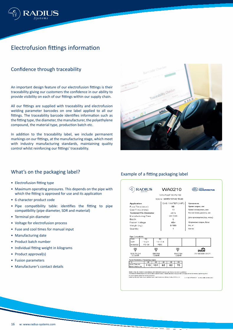
What’s on the packaging label?
• Electrofusion fitting type
• Maximum operating pressures. This depends on the pipe with which the fitting is approved for use and its application
• 6 character product code
• Pipe compatibility table: identifies the fitting to pipe compatibility (pipe diameter, SDR and material)
• Terminal pin diameter
• Voltage for electrofusion process
• Fuse and cool times for manual input
• Manufacturing date
• Product batch number
• Individual fitting weight in kilograms
• Product approval(s)
• Fusion parameters
• Manufacturer’s contact details
Example of a fitting packaging label
t: +44 (0)1773 811112 e: [email protected] 17
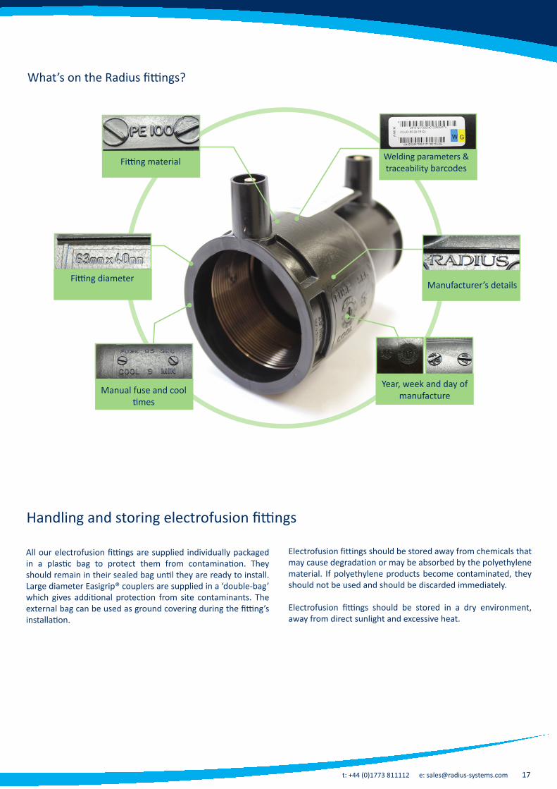
Welding parameters & traceability barcodes
What’s on the Radius fittings?
All our electrofusion fittings are supplied individually packaged in a plastic bag to protect them from contamination. They should remain in their sealed bag until they are ready to install. Large diameter Easigrip® couplers are supplied in a ‘double-bag’ which gives additional protection from site contaminants. The external bag can be used as ground covering during the fitting’s installation.
Electrofusion fittings should be stored away from chemicals that may cause degradation or may be absorbed by the polyethylene material. If polyethylene products become contaminated, they should not be used and should be discarded immediately.
Electrofusion fittings should be stored in a dry environment, away from direct sunlight and excessive heat.
Fitting diameter
Fitting material
Manufacturer’s details
Manual fuse and cool times
Handling and storing electrofusion fittings
Year, week and day of manufacture
18 w: www.radius-systems.com
S y s t e m s
Cleanliness
• The electrofusion fitting must remain in its protective packaging until it is placed on the prepared pipe surface. Do not touch the pipe and fitting jointing surfaces
• The clean pipe surface must be correctly prepared without excessive scraping. Industry approved pipe surface preparation tools must be used
• Following pipe surface preparation, do not touch or wipe the pipe surface
• If the prepared pipe surface becomes contaminated before making the electrofusion joint, it should be cleaned, dried and re-prepared using the approved tools and procedure, without excessive scraping
• Once prepared, the joint must be made promptly to prevent contamination of the pipe surface.
Pressure
• The pipe surface must be correctly prepared without excessive scraping, as this may lead to a poor quality fusion joint
• When making a socket joint, the pipe ends must be cut square and must be fully inserted into the fitting’s socket until it reaches the insertion stops
• Where there is evidence of pipe ovality, the pipe must be re-rounded before the electrofusion fitting is placed on the pipe
• Alignment clamps must be used for all socket fittings
• A calibrated tapping tee top loading clamp capable of applying the correct force must be used for top loading saddle fittings.
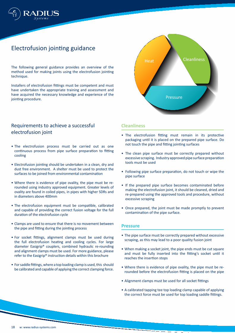
Electrofusion jointing guidance
The following general guidance provides an overview of the method used for making joints using the electrofusion jointing technique.
Installers of electrofusion fittings must be competent and must have undertaken the appropriate training and assessment and have acquired the necessary knowledge and experience of the jointing procedure.
Requirements to achieve a successful electrofusion joint
• The electrofusion process must be carried out as one continuous process from pipe surface preparation to fitting cooling
• Electrofusion jointing should be undertaken in a clean, dry and dust free environment. A shelter must be used to protect the surfaces to be joined from environmental contamination
• Where there is evidence of pipe ovality, the pipe must be re-rounded using industry approved equipment. Greater levels of ovality are found in coiled pipes, in pipes with higher SDRs and in diameters above 400mm
• The electrofusion equipment must be compatible, calibrated and capable of providing the correct fusion voltage for the full duration of the electrofusion cycle
• Clamps are used to ensure that there is no movement between the pipe and fitting during the jointing process
• For socket fittings, alignment clamps must be used during the full electrofusion heating and cooling cycles. For large diameter Easigrip® couplers, combined hydraulic re-rounding and alignment clamps must be used. For more guidance, please refer to the Easigrip® instruction details within this brochure
• For saddle fittings, where a top loading clamp is used, this should be calibrated and capable of applying the correct clamping force.
Heat Cleanliness
Pressure

t: +44 (0)1773 811112 e: [email protected] 19
Heat
• When making electrofusion joints, it is important to ensure that the generator (power supply) and the electrofusion control box are compatible with one another and must be capable of delivering the maximum power requirements at the stated voltage to the fitting
• The following table identifies the fittings' maximum power requirements at the stated voltage for the electrofusion process. These must be delivered to the fitting without interruption, for the full duration of the electrofusion heating cycle:
• For Easigrip® couplers 450 mm and above, equipment compatible with Easigrip® couplers must be used. Please refer to the Easigrip® instruction details within this brochure
• The electrofusion alignment or top loading clamp must be left in place for the full duration of the fusion and cooling cycles
• If the electrofusion process is interrupted before the fusion cycle is completed, do not re-heat the fitting. The fitting must not be commissioned.
Fitting type Terminal pin diameter
Fitting's maximum power requirement
Fitting voltage supply
Saddle fittings 4.0 mm 2.5 kW at 40 V rms 39 to 40 V rms
Socket fittings up to 280 mm 4.0 mm 2.5 kW at 40 V rms 39 to 40 V rms
Socket fittings 315 to 400 mm 4.0 mm 4.0 kW at 40 V rms 39 to 40 V rms
Socket fittings 315 to 400 mm 5.7 mm 4.0 kW at 80 V rms 78 to 80 V rms
Socket fittings above 400 mm 5.7 mm 4.8 kW at 80 V rms 78 to 80 V rms
Quality assessment
• Following the electrofusion process, the fitting should be inspected to ensure that the fusion indicator(s) is (are) raised. The fusion indicator identifies that the electrofusion process has taken place. It is not confirmation of a quality joint
• For a good quality joint, there should be no visible melted material outside the fitting’s fusion zone
• At the end of the electrofusion cycle, the control box should be checked to confirm that the cycle has completed without error
• The fusion joint record data should be retrievable for quality inspection
• Each joint should be marked with the joint reference details
• Follow industry approved pressure test procedures before commissioning the joint
20 w: www.radius-systems.com
S y s t e m s
Follow the instructions on the electrofusion control box
Melt indicators show that the fusion process has taken place. It is not confirmation of a quality joint. Clamps must remain in place during the full cooling period
9 11
Scan or manually enter the fitting’s fusion details in the control box and start the welding process
10
Remove the clamps after the cooling period has elapsed. The joint is complete. Follow industry approved pressure test procedures before commissioning the joint.
12
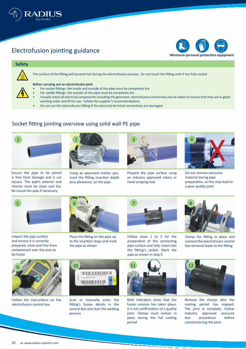
Safety
Before carrying out an electrofusion joint• For socket fittings: the inside and outside of the pipe must be completely dry• For saddle fittings: the outside of the pipe must be completely dry• Visually check all electrical components including the generator, electrofusion control box and all cables to ensure that they are in good
working order and fit for use. Follow the supplier’s recommendations• Do not use the electrofusion fitting if the electrical terminal connections are damaged.
Electrofusion jointing guidance
Prepare the pipe surface using an industry approved rotary or hand scraping tool
3
Do not remove excessive material during pipe preparation, as this may lead to a poor quality joint
4 XEnsure the pipe to be joined is free from damage and is cut square. The pipe’s exterior and interior must be clean and dry. Re-round the pipe if necessary
Using an approved marker pen, mark the fitting insertion depth plus allowance, on the pipe
1 2
The surface of the fitting will become hot during the electrofusion process. Do not touch the fitting until it has fully cooled
Minimum personal protection equipment
Socket fitting jointing overview using solid wall PE pipe
Inspect the pipe surface and ensure it is correctly prepared, clean and free from contaminant over the area to be fused
Place the fitting on the pipe up to the insertion stops and mark the pipe as shown
Follow steps 1 to 5 for the preparation of the connecting pipe surface and fully insert into the fitting’s socket. Mark the pipe as shown in step 6
Clamp the fitting in place and connect the electrofusion control box terminal leads to the fitting
6 7 85
t: +44 (0)1773 811112 e: [email protected] 21
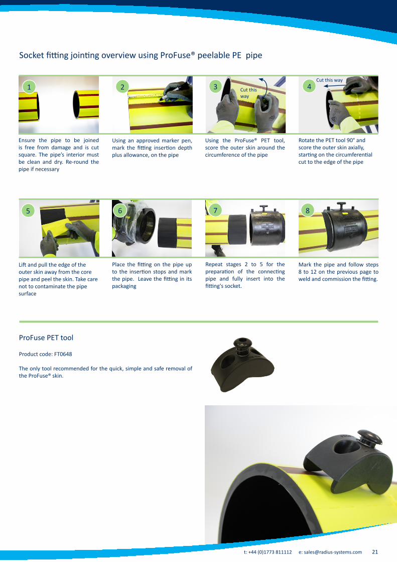
Using the ProFuse® PET tool, score the outer skin around the circumference of the pipe
3
Rotate the PET tool 90° and score the outer skin axially, starting on the circumferential cut to the edge of the pipe
4
Ensure the pipe to be joined is free from damage and is cut square. The pipe’s interior must be clean and dry. Re-round the pipe if necessary
Using an approved marker pen, mark the fitting insertion depth plus allowance, on the pipe
1 2
Socket fitting jointing overview using ProFuse® peelable PE pipe
Lift and pull the edge of the outer skin away from the core pipe and peel the skin. Take care not to contaminate the pipe surface
Place the fitting on the pipe up to the insertion stops and mark the pipe. Leave the fitting in its packaging
Repeat stages 2 to 5 for the preparation of the connecting pipe and fully insert into the fitting's socket.
Mark the pipe and follow steps 8 to 12 on the previous page to weld and commission the fitting.
6 7 85
Cut this way
Cut this way
ProFuse PET tool
Product code: FT0648
The only tool recommended for the quick, simple and safe removal of the ProFuse® skin.
22 w: www.radius-systems.com
S y s t e m s
Safety
3
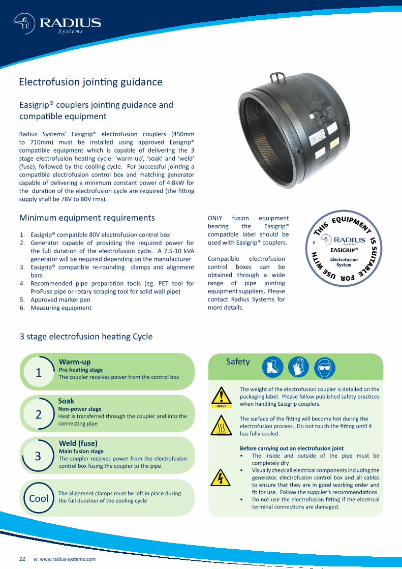
Easigrip® couplers jointing guidance and compatible equipment
3 stage electrofusion heating Cycle
Warm-upPre-heating stageThe coupler receives power from the control box
SoakNon-power stageHeat is transferred through the coupler and into the connecting pipe
Weld (fuse)Main fusion stage The coupler receives power from the electrofusion control box fusing the coupler to the pipe
Radius Systems' Easigrip® electrofusion couplers (450mm to 710mm) must be installed using approved Easigrip® compatible equipment which is capable of delivering the 3 stage electrofusion heating cycle: ‘warm-up’, ‘soak’ and ‘weld’ (fuse), followed by the cooling cycle. For successful jointing a compatible electrofusion control box and matching generator capable of delivering a minimum constant power of 4.8kW for the duration of the electrofusion cycle are required (the fitting supply shall be 78V to 80V rms).
Minimum equipment requirements
1. Easigrip® compatible 80V electrofusion control box 2. Generator capable of providing the required power for
the full duration of the electrofusion cycle. A 7.5-10 kVA generator will be required depending on the manufacturer
3. Easigrip® compatible re-rounding clamps and alignment bars
4. Recommended pipe preparation tools (eg. PET tool for ProFuse pipe or rotary scraping tool for solid wall pipe)
5. Approved marker pen6. Measuring equipment
The weight of the electrofusion coupler is detailed on the packaging label. Please follow published safety practices when handling Easigrip couplers.
The surface of the fitting will become hot during the electrofusion process. Do not touch the fitting until it has fully cooled.
Before carrying out an electrofusion joint• The inside and outside of the pipe must be
completely dry• Visually check all electrical components including the
generator, electrofusion control box and all cables to ensure that they are in good working order and fit for use. Follow the supplier’s recommendations
• Do not use the electrofusion fitting if the electrical terminal connections are damaged.
The alignment clamps must be left in place during the full duration of the cooling cycle
1
2
Cool
ONLY fusion equipment bearing the Easigrip® compatible label should be used with Easigrip® couplers.
Compatible electrofusion control boxes can be obtained through a wide range of pipe jointing equipment suppliers. Please contact Radius Systems for more details.
Electrofusion jointing guidance

t: +44 (0)1773 811112 e: [email protected] 23
Melt indicators show that the fusion process has taken place. It is not confirmation of a quality joint. Clamps must remain in place during the full cooling period.
Inspect the pipe and ensure it is free from damage and the pipe surface is clean and dry.
Top loading tapping tee jointing guidance
Using the electrofusion fitting as a guide, mark the area of the pipe to prepare for electrofusion jointing, using an approved marker pen.
Mark the area as shown.
1 2 3
Prepare the pipe using an industry approved hand scraping tool.
4
Inspect the pipe surface and ensure it is clean and free from contamination.
Using an approved calibrated clamp, secure the saddle fitting in place. Ensure the correct clamping force is applied (check clamp indicator).
Connect the electrofusion control box terminal leads to the fitting and follow the instructions on the control box.
Do not remove the cutter from the stack. Ensure the top of the cutter is flush with the top of the stack.
5 6 7 8
Prepare the outlet of the tapping tee and place the socket fitting onto the outlet. Prepare the service pipe and make the socket joint following the socket fitting jointing procedure on page 20.
Pressure test the service before commissioning.
1. Tapping the mainUse a 12 mm hexagonal T key and turn in a clockwise direction until the cutter cuts through the top of the main2. Retracting the cutterTurn the T key in an anti-clockwise direction until the top of the cutter is flush with the top of the stack.
9 1110
Check the O-ring seal is in place at the top of the stack and adequately tighten the cap. Check for leakage using industry best practice. The connection and commissioning are now complete.
12Tapping the main
Retracting the cutter
IMPORTANT NOTE
A thread follower is supplied with our range of large diameter tapping tee products for diameters 200 mm and above. Where a thread follower is included, a white label will be visible when the tapping tee cap is removed.
Thread followers ensure that the threads within the body of the tapping tee products are not overstressed when tapping the main. The follower should be retracted and removed when the tapping operation is complete. Do not remove the cutter from the stack. Ensure the top of the cutter is flush with the top of the stack.
Cutter
Thread follower
Cutter
White label on top of thread follower
Radius Systems' tapping tee products, including PurgeTee™ and Anaconda® are supplied with an integral cutter within the body of the tapping tee. This is a 'non-captive cutter'. During the commissioning of the tapping tee product, some let-by of gas or water past the cutter threads may occur. This is normal and consistent with the design functionality of the tapping tee and will cease once the commissioning operation is complete. It is essential that the following tapping tee installation guidance is adhered to.
Using solid wall PE pipes
24 w: www.radius-systems.com
S y s t e m s
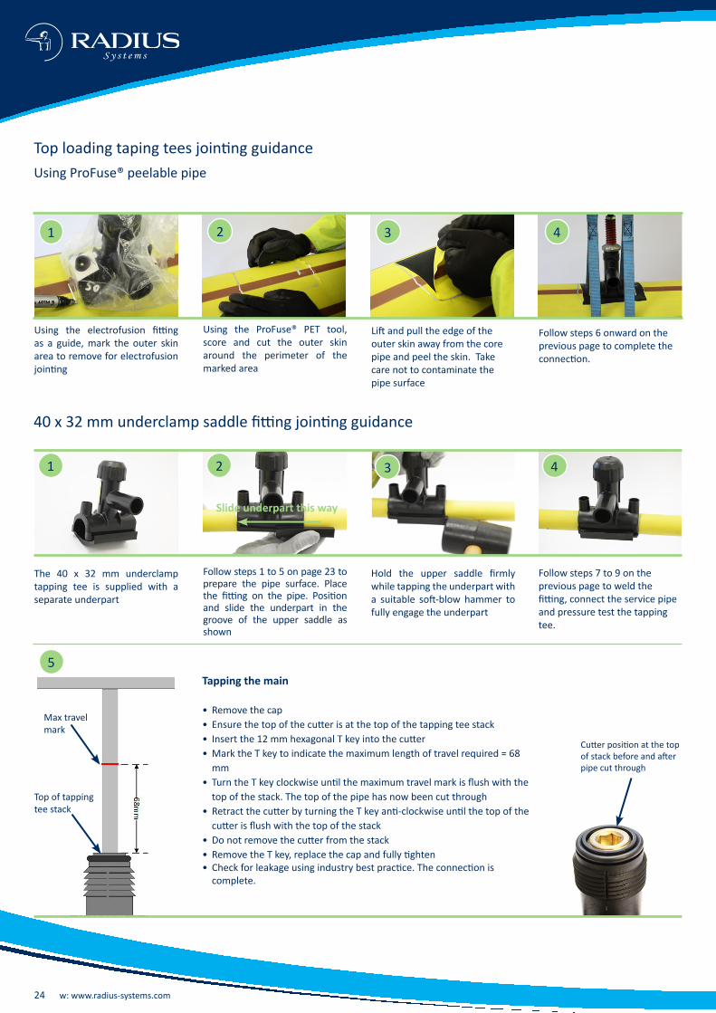
Top loading taping tees jointing guidance Using ProFuse® peelable pipe
Using the ProFuse® PET tool, score and cut the outer skin around the perimeter of the marked area
1 2 3 4
Using the electrofusion fitting as a guide, mark the outer skin area to remove for electrofusion jointing
Lift and pull the edge of the outer skin away from the core pipe and peel the skin. Take care not to contaminate the pipe surface
Follow steps 6 onward on the previous page to complete the connection.
40 x 32 mm underclamp saddle fitting jointing guidance
1 2 3 4
Follow steps 1 to 5 on page 23 to prepare the pipe surface. Place the fitting on the pipe. Position and slide the underpart in the groove of the upper saddle as shown
The 40 x 32 mm underclamp tapping tee is supplied with a separate underpart
Hold the upper saddle firmly while tapping the underpart with a suitable soft-blow hammer to fully engage the underpart
Follow steps 7 to 9 on the previous page to weld the fitting, connect the service pipe and pressure test the tapping tee.
Top of tapping tee stack
Max travel mark
Tapping the main
• Remove the cap• Ensure the top of the cutter is at the top of the tapping tee stack• Insert the 12 mm hexagonal T key into the cutter• Mark the T key to indicate the maximum length of travel required = 68
mm • Turn the T key clockwise until the maximum travel mark is flush with the
top of the stack. The top of the pipe has now been cut through• Retract the cutter by turning the T key anti-clockwise until the top of the
cutter is flush with the top of the stack• Do not remove the cutter from the stack• Remove the T key, replace the cap and fully tighten• Check for leakage using industry best practice. The connection is
complete.
Cutter position at the top of stack before and after pipe cut through
5
Slide underpart this way

t: +44 (0)1773 811112 e: [email protected] 25
PurgeTee™ for gas applications
Principle of operation
Fuse the PurgeTee™ onto the PE main, using the same procedure for saddle fittings in this document
Remove the outlet cap and carry out a pressure test to prove weld integrity
Fit the purge tube to the PurgeTee’s elbow outlet using the reusable thread adaptor (see page 12).
Using a short arm T key, cut a hole into the PE main, as shown. Wind the cutter back to the top of the stack. Do not remove the cutter
1 2 3
Open the valve on the purge tube to allow the gas / air to escape through the PurgeTee™
When the purging operation is complete, close the valve and wind the cutter down, so that it plugs the cut hole in the crown of the PE pipe
Now that the flow of gas is controlled, remove the purge tube and adaptor. Check the o’ring seal is in place at the top of the stack and adequately tighten the cap. Check for leakage using industry best practice.
4 5 6
For complete jointing guidance and jointing videos, please visit our website www.radius-systems.com. For further jointing advice, please contact our technical support team on: t: +44 (0)1773 811112 e: [email protected].

26 w: www.radius-systems.com
S y s t e m s
present between the pipe and fitting's jointing surfaces.
?Why do I need to leave the fitting in its packaging right up to the point of connection?
Electrofusion fittings are supplied in sealed packaging to prevent contamination of the jointing surfaces. It is therefore recommended that the packaging is only removed at the point of connection to eliminate contamination of the fitting's jointing surface.
? Why do I need to use electrofusion alignment clamps?
Electrofusion alignment
clamps are used for pipe to socket fitting connection and ensure that the pipe and fitting are in true alignment with one another and that there is a uniform gap between the pipe's outer surface and the fitting's internal surface. This ensures that during the heating phase of the electrofusion process the molten material is evenly distributed around the annular gap between the pipe and the fitting for joint quality.
?Why do I need to use a top loading clamp when making a top loading tapping tee connection onto a pipeline?
Top loading clamps are used
with top loading tapping tees to ensure that the correct force is applied between the tapping tee body and the connecting pipe, to achieve the correct weld interface pressure during the electrofusion process. Failure to adequately clamp the tapping tee body will result in incorrect fusion pressure and potential premature failure of the electrofusion joint.
? When making an electrofusion fitting joint, what is the power requirements and what size of generator do I need?
The size of generator is fully
dependent on the age and efficiency of the generator. Please refer to the power requirements and generator size table on page 19 in this brochure. The generator supplier will be able to confirm the generator size required for a given fitting.
?I have stock of identical fittings, but with different electrofusion fuse and cool times. Why is this?
Radius Systems have a programme of continuous product development and improvement and this may result in changes to a fitting's design, including changes to a fitting's fuse and cool times. The correct fuse and cool times for each fitting are identified on the individual fitting's packaging label. Always refer to the packaging label for the up to date fitting's details but if in doubt, please contact Radius Systems.
? Radius Systems have supplied fittings with 4.0 mm terminal pins. However, my electrofusion control box is fitted with 4.7 mm terminal pin connection leads. How should I proceed?
Terminal pin adaptors are available to convert the terminal pin connection leads from 4.7 mm to 4.0 mm. These pin converters are available from electrofusion tooling and equipment suppliers.
?When making connections onto coiled pipes, I have noticed that the pipe is not truly circular, unlike straight pipes. What should I do when carrying out an electrofusion joint?
When polyethylene pipes are supplied in coil format, there will be a greater level of pipe ovality than that of pipe supplied in straight lengths. The pipe should be re-rounded using approved re-rounding clamps at the position where the joint is to be made.
?Why do I need to prepare the pipe surface before making an electrofusion joint?
To ensure a successful welded connection is achieved, it is important that when a joint is made, no contaminants are present at the joint interface or within the welded connection. During storage, transportation, handling and installation, the external surface of a polyethylene pipe will become contaminated with dirt and debris, which must be removed before making an electrofusion
joint, using recommended pipe surface preparation techniques (see jointing overview on p20 to 24).
?Once I have prepared the pipe surface for electrofusion jointing, how long can I leave the pipe surface exposed before I make the joint?
Making an electrofusion
joint is a continuous process and once the pipe surface has been prepared, the electrofusion joint should be made without delay. Delay in making the joint, may result in contamination of the pipe surface, which could lead to premature failure of the electrofusion joint.
?Can I prepare the pipe surface and then use wipes to remove airborne dust and dirt?
The use of wipes to remove airborne dust and dirt is not recommended as the final method for pipe preparation. The only acceptable method of final pipe surface preparation is the use of a hand or rotary pipe scraper. Wipes and towels are only recommended to remove dust and dirt before using a hand or rotary scraper.
?When preparing the surface of a polyethylene pipe for electrofusion jointing, what equipment should I use?
For tapping tee connections,
an industry approved ‘hand scraper’ should be used. For socket fittings, industry approved rotary pipe surface preparation tools are preferred. Such tools have the added benefit of removing a continuous layer of polyethylene material around the pipe's circumference for the full length of the socket.
?Why is it recommended to use a welding shelter when making electrofusion joints?
Welding shelters are
recommended to ensure that environmental contamination on the surfaces to be joined is minimised:
• Airborne dust in dry weather • Rain and moisture in wet
conditions When making an electrofusion
joint, dust, dirt, rain and moisture act as contaminants and will reduce the quality of the electrofusion joint, if
?Why do Radius Systems electrofusion fittings use exposed wire technology?
Exposed wire technology
is where the metallic electrofusion heating element is visible, whilst being embedded within the fitting's body. Radius Systems consider that the exposed wire technology provides a more efficient heat transfer during the electrofusion process, whilst increasing joint integrity.
?I want to use an electrofusion coupler as a repair coupler. Is this possible and what do I need to do?
Electrofusion couplers may be used as repair couplers by removing the fitting's centre stops. It is important that the fitting's internal surface, including the heating wire element, do not become damaged or contaminated during the removal of the stops.
? Why are there 2 different terminal pin dimensions for electrofusion fittings?
Different terminal pin diameters are used for 40 and 80 Volt fittings:
• 4.0 mm terminal pins are used for 40 Volt electrofusion fittings
• 5.7 mm terminal pins are used for 80 Volt electrofusion fittings in larger diameter.

t: +44 (0)1773 811112 e: [email protected] 27
? If my generator runs out of fuel part way through the electrofusion joint, is it acceptable to add more fuel to the generator and continue from where I left off?
It is important to check the generator and ensure that there is an adequate amount of fuel to complete the electrofusion process, before making a joint. If a generator runs out of fuel part way through the fusion cycle, the electrofusion process should be terminated and under no circumstances should a second electrofusion process be undertaken. Once cool, the fitting must be removed from the system.
?Once I have satisfactorily welded a tapping tee onto a pipeline, is it acceptable to proceed to tap into the live main?
Tapping into the main should
only take place after the tapping tee's cooling time has elapsed and the fitting is fully cooled. All joints should be tested for leak tightness before tapping the live main.
? What equipment do I need to tap into the main?
Radius Systems' tapping tees are fitted with an integral cutter. We only recommend a 12 mm hexagonal T key to commission the tapping tee. The T key allows the application of a symmetrical torque to the tapping tee when cutting through the main. Radius Systems do not recommend the use of single arm, ratchet or power tools when commissioning tapping tees due to the possible damage caused to the tapping tee internal threads.
? In which position should the tapping tee cutter be, once I have commissioned the service?
The tapping tee cutter must
always remain in the tapping tee. The top of the cutter should be flush with the top of the tapping tee stack.
?Why is there a thread follower included with the large diameter tapping tees?
The thread follower included in all large diameter tapping tees 200 mm and above, is designed to ensure that the threads within the body of the tapping tee are not overstressed when tapping the main.
?How do I know if there is a thread follower in the tapping tee?
A thread follower is included in all tapping tees 200 mm and above. It is positioned directly above and engaged with the tapping tee cutter. A white label is applied to the top of the thread follower to indicate its presence.
?Once I have commissioned the tapping tee, should I leave the thread follower in the fitting?
The thread follower is used
solely for the tapping tee commissioning procedure and should be removed once the procedure is completed. Retract the thread follower to the top of the tapping tee stack and remove carefully. The cutter must remain in the tapping tee. Ensure that the top of the cutter is flush with the top of the tapping tee stack.
?Is it normal for the fitting's external surface to become hot during and immediately after the electrofusion heating cycle?
Electrofusion joints are made
by applying a constant voltage to the fitting's terminal connections, which causes the fitting's electrofusion heating element to become hot. This in turn, heats the adjoining pipe surface, resulting in a homogeneous melt between the pipe and fitting. This heating process causes the fitting to become hot during and for some time after the heating cycle. Do not touch the fitting until the fitting has fully cooled.
?Why do Radius Systems' large diameter electrofusion fittings utilise a 3 stage heating cycle?
Radius Systems' large diameter
electrofusion couplers use a 3 stage heating cycle - Heat - Soak - Weld, to ensure that the heat between the fitting and the pipe is uniformly transferred for optimum joint quality. The 3 stage heating cycle also allows for the fusion of the fitting to be carried out as one operation and specific electrofusion control boxes are required. Please refer to p22 of this brochure for more details.
? Who can I contact if I have additional product or technical queries regarding Radius Systems' electrofusion fittings?
If you have additional questions relating to our electrofusion fittings, please contact Radius Systems’ Sales or Technical Support teams via telephone or email:
Sales: +44 (0)1773 811112 [email protected]
Technical support: +44 (0)1773 811112 [email protected]
Cutter
Thread follower
Cutter position at top of stack after tapping the main
Thread follower label on tapping tees 200 mm and above
DISCLAIMERRadius Systems have made every effort to ensure that the information contained within this document is accurate. No legal responsibility will be accepted for any errors or omissions, whether they result from negligence or other cause. Radius Systems will not accept any legal responsibility or claim for consequential loss or otherwise, resulting from the use of this information. It is provided in good faith and remains entirely the responsibility of the recipient(s) to satisfy themselves at all times of the applicability of this information in relation to a given application or project.
As part of the Radius Systems program of continuous improvement, we reserve the right to amend the content of this publication without notice. The information supplied in this document is correct at the time of publication.
Distributor’s stamp
For more information please visit our website: www.radius-systems.com or contact us:
UK Head Office Radius Systems LtdRadius HouseBerristow LaneSouth Normanton, AlfretonDerbyshireDE55 2JJ, UKt: +44 (0)1773 811112e: [email protected]
Northern Ireland and Republic of Ireland salesRadius SystemsHalfpenny Valley Industrial EstateParkview StreetPortadown RoadLurganCo ArmaghBT66 8TP, UKt: +44 (0)2838 446060e: [email protected]
Radius SystemsRadius Systems are a market leader in the innovation and manufacture of plastic pipe systems for the utilities and construction industries. With extensive research and development at the heart of our products and systems, we take care of the entire pipe life cycle - from design and manufacture through to installation, repair and rehabilitation. We strive to improve industry practices, with good health and safety policies at the forefront of our philosophy of ‘getting it right first time’. Our continuous customer inspired research and development, combined with successful customer partnerships represent our total dedication to the plastic piping industry.
Manufacturing facilities With 2 production sites in the UK, we have complete control over quality and the
ability to meet our customers' expectations
Innovative approach We are leaders in our field with a history of research and new product
development. Practicality, durability and adaptability are all high on our agenda to meet our clients’ needs
Flexible product and service provision Our comprehensive range of services is designed to fit the variable demands of
our clients’ developments in pipes, fittings, training and support services
Reliability and safety With over 50 years experience in pipe design and manufacture, our clients know
that they can count on us to meet not just their product and service needs, but also their delivery and safety requirements
Outstanding customer service We have a dedicated Customer Services team to answer queries from our
customers in the UK and overseas. Our service is not just about the delivery of products - contact our team if you have a product or installation enquiry or a post-delivery query
EF-fi
tting
s-Se
pt-1
7.in
dd


