Hardware-efficient quantum random access memory with hybrid quantum acoustic systems Connor T. Hann, 1 Chang-Ling Zou, 2 Yaxing Zhang, 1 Yiwen Chu, 3 Robert J. Schoelkopf, 1 Steven M. Girvin, 1 and Liang Jiang 1 1 Departments of Applied Physics and Physics, Yale University, New Haven, Connecticut 06511, USA 2 Key Laboratory of Quantum Information, CAS, University of Science and Technology of China, Hefei, China. 3 Department of Physics, ETH Z¨ urich, 8093 Z¨ urich, Switzerland Hybrid quantum systems in which acoustic resonators couple to superconducting qubits are promising quantum information platforms. High quality factors and small mode volumes make acoustic modes ideal quantum memories, while the qubit-phonon coupling enables the initialization and manipulation of quantum states. We present a scheme for quantum computing with multimode quantum acoustic systems, and based on this scheme, propose a hardware-efficient implementation of a quantum random access memory (qRAM). Quantum information is stored in high-Q phonon modes, and couplings between modes are engineered by applying off-resonant drives to a transmon qubit. In comparison to existing proposals that involve directly exciting the qubit, this scheme can offer a substantial improvement in gate fidelity for long-lived acoustic modes. We show how these engineered phonon-phonon couplings can be used to access data in superposition according to the state of designated address modes—implementing a qRAM on a single chip. Introduction.—The coupling of superconducting qubits to microwave resonators, termed circuit quantum electro- dynamics (cQED) [1, 2], constitutes one of today’s most promising quantum computing architectures. Microwave modes provide good quantum memories [3], while su- perconducting nonlinearities enable the initialization [4], manipulation [5, 6], readout [7], and protection [8, 9] of quantum states encoded in microwave photons. How- ever, long microwave wavelengths pose a potential limi- tation to the scalability of cQED systems. On-chip res- onators face trade-offs between compactness and quality factor [10, 11], and microwave modes with millisecond co- herence or better have thus far only been demonstrated in large 3D cavities [3, 12]. Recently, coherent couplings between superconducting qubits and acoustic resonators have been demonstrated in a remarkable series of experiments [13–25]. These so- called circuit quantum acoustodynamic (cQAD) systems (Fig. 1) possess many of the advantageous properties of cQED systems, e.g., superconducting qubits can be used to generate arbitrary superpositions of acoustic Fock states [17, 21], and phonon-number resolving measure- ments can be performed in the dispersive regime [24, 25]. Yet relative to electromagnetic modes, acoustic modes can provide dramatic benefits in terms of size and coher- ence times. The velocities of light and sound differ by five orders of magnitude, and short acoustic wavelengths enable the fabrication of ultra-compact phononic res- onators [26]. Furthermore, acoustic modes can be excep- tionally well-isolated from their environments—quality factors in excess of 10 10 were recently demonstrated in GHz frequency phononic crystal resonators [27]. A va- riety of applications for such platforms have been pro- posed, including quantum transduction [28], entangle- ment generation [29, 30], and quantum signal process- ing [31, 32], but surprisingly the direct use of cQAD sys- tems for quantum computing has received relatively little (a) (b) (c) FIG. 1. Hybrid acoustic-superconducting systems for mul- timode cQAD. A transmon qubit (red) is piezoelectrically coupled to (a) a bulk acoustic wave resonator, (b) a surface acoustic wave resonator, or (c) an array of phononic crystal resonators. attention, with the notable exception of Ref. [33]. In this work, we propose a hardware-efficient and scalable quantum computing architecture for multimode cQAD systems. Quantum information is stored in high- quality acoustic modes, and interactions between modes are engineered by applying off-resonant drives to an an- cillary superconducting transmon qubit. During these operations, the transmon is only virtually excited, so the effects of transmon decoherence are mitigated. This is a crucial property, since the transmon’s decoherence rate can exceed that of the phonons by orders of magnitude. In comparison to existing proposals that involve directly exciting the transmon [33, 34], this virtual approach can offer substantial improvement in gate fidelity for long- lived phonons. This scheme is also directly applicable to multimode cQED systems [34]. Furthermore, to demonstrate the benefits that the pro- posed cQAD architecture affords in hardware efficiency, we propose an implementation of a quantum random ac- cess memory (qRAM) [35, 36]. A classical RAM is a device that can query a database. Given an address j as input, the RAM outputs the element D j stored at posi- tion j in the database. Analogously, a qRAM is a device that, when provided with a superposition of addresses, arXiv:1906.11340v1 [quant-ph] 26 Jun 2019
Transcript
Hardware-efficient quantum random access memory with hybrid quantum acousticsystems
Connor T. Hann,1 Chang-Ling Zou,2 Yaxing Zhang,1 Yiwen Chu,3
Robert J. Schoelkopf,1 Steven M. Girvin,1 and Liang Jiang1
1Departments of Applied Physics and Physics, Yale University, New Haven, Connecticut 06511, USA2Key Laboratory of Quantum Information, CAS,
University of Science and Technology of China, Hefei, China.3Department of Physics, ETH Zurich, 8093 Zurich, Switzerland
Hybrid quantum systems in which acoustic resonators couple to superconducting qubits arepromising quantum information platforms. High quality factors and small mode volumes makeacoustic modes ideal quantum memories, while the qubit-phonon coupling enables the initializationand manipulation of quantum states. We present a scheme for quantum computing with multimodequantum acoustic systems, and based on this scheme, propose a hardware-efficient implementationof a quantum random access memory (qRAM). Quantum information is stored in high-Q phononmodes, and couplings between modes are engineered by applying off-resonant drives to a transmonqubit. In comparison to existing proposals that involve directly exciting the qubit, this scheme canoffer a substantial improvement in gate fidelity for long-lived acoustic modes. We show how theseengineered phonon-phonon couplings can be used to access data in superposition according to thestate of designated address modes—implementing a qRAM on a single chip.
Introduction.—The coupling of superconducting qubitsto microwave resonators, termed circuit quantum electro-dynamics (cQED) [1, 2], constitutes one of today’s mostpromising quantum computing architectures. Microwavemodes provide good quantum memories [3], while su-perconducting nonlinearities enable the initialization [4],manipulation [5, 6], readout [7], and protection [8, 9] ofquantum states encoded in microwave photons. How-ever, long microwave wavelengths pose a potential limi-tation to the scalability of cQED systems. On-chip res-onators face trade-offs between compactness and qualityfactor [10, 11], and microwave modes with millisecond co-herence or better have thus far only been demonstratedin large 3D cavities [3, 12].
Recently, coherent couplings between superconductingqubits and acoustic resonators have been demonstratedin a remarkable series of experiments [13–25]. These so-called circuit quantum acoustodynamic (cQAD) systems(Fig. 1) possess many of the advantageous propertiesof cQED systems, e.g., superconducting qubits can beused to generate arbitrary superpositions of acoustic Fockstates [17, 21], and phonon-number resolving measure-ments can be performed in the dispersive regime [24, 25].Yet relative to electromagnetic modes, acoustic modescan provide dramatic benefits in terms of size and coher-ence times. The velocities of light and sound differ byfive orders of magnitude, and short acoustic wavelengthsenable the fabrication of ultra-compact phononic res-onators [26]. Furthermore, acoustic modes can be excep-tionally well-isolated from their environments—qualityfactors in excess of 1010 were recently demonstrated inGHz frequency phononic crystal resonators [27]. A va-riety of applications for such platforms have been pro-posed, including quantum transduction [28], entangle-ment generation [29, 30], and quantum signal process-ing [31, 32], but surprisingly the direct use of cQAD sys-tems for quantum computing has received relatively little
(a) (b) (c)
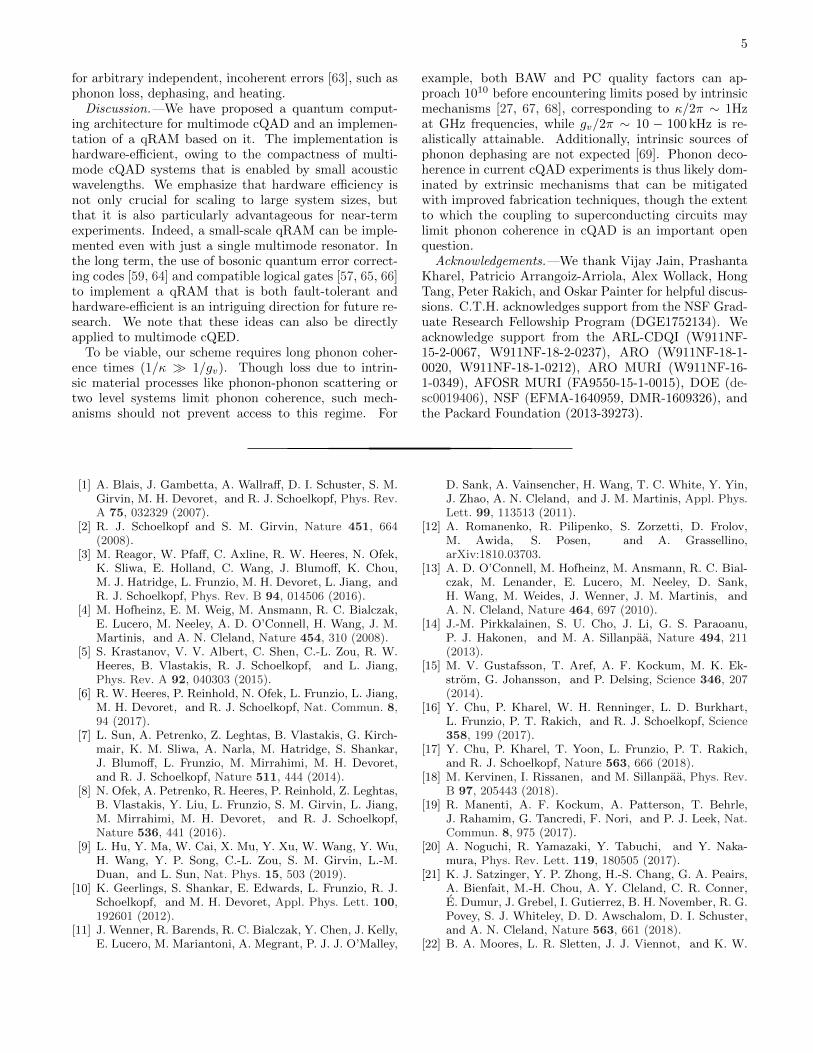
FIG. 1. Hybrid acoustic-superconducting systems for mul-timode cQAD. A transmon qubit (red) is piezoelectricallycoupled to (a) a bulk acoustic wave resonator, (b) a surfaceacoustic wave resonator, or (c) an array of phononic crystalresonators.
attention, with the notable exception of Ref. [33].
In this work, we propose a hardware-efficient andscalable quantum computing architecture for multimodecQAD systems. Quantum information is stored in high-quality acoustic modes, and interactions between modesare engineered by applying off-resonant drives to an an-cillary superconducting transmon qubit. During theseoperations, the transmon is only virtually excited, so theeffects of transmon decoherence are mitigated. This is acrucial property, since the transmon’s decoherence ratecan exceed that of the phonons by orders of magnitude.In comparison to existing proposals that involve directlyexciting the transmon [33, 34], this virtual approach canoffer substantial improvement in gate fidelity for long-lived phonons. This scheme is also directly applicable tomultimode cQED systems [34].
Furthermore, to demonstrate the benefits that the pro-posed cQAD architecture affords in hardware efficiency,we propose an implementation of a quantum random ac-cess memory (qRAM) [35, 36]. A classical RAM is adevice that can query a database. Given an address j asinput, the RAM outputs the element Dj stored at posi-tion j in the database. Analogously, a qRAM is a devicethat, when provided with a superposition of addresses,
arX
iv:1
906.
1134
0v1
[qu
ant-
ph]
26
Jun
2019
2
returns a correlated superposition of data [37],
N∑j=1
αj |j〉a |0〉bqRAM−−−−→
N∑j=1
αj |j〉a |Dj〉b , (1)
where the subscripts a and b denote the address andoutput qubit registers, respectively. The ability to per-form such queries efficiently, i.e. in logN time, is aprerequisite for a variety of quantum algorithms thatprovide speedups over their classical counterparts [38–40]. However, building a qRAM is a highly non-trivialtask; even a small-scale qRAM of the sort describedin Ref. [35] has yet to be experimentally demonstrated.One major challenge is that, to query a database of sizeN , a qRAM requires order N quantum resources [36].Hardware-efficiency is thus crucial for qRAM queries oflarge datasets, and in our implementation this efficiencyis enabled by the on-chip integration of superconductingcircuits with compact, high-quality acoustic resonators.Our proposal both provides a roadmap for a near-termdemonstration of a qRAM, and improves qRAM feasi-bility in the long term by reducing physical resource re-quirements.
Quantum computing in cQAD.—In multimode cQAD,a transmon qubit is piezoelectrically coupled to a collec-tion of acoustic modes. These modes can be supportedin bulk acoustic wave (BAW) [16–18] or surface acous-tic wave (SAW) [19–24] resonators, or in an array ofphononic crystal (PC) resonators [25] (Fig. 1). Qualityfactors of ≈ 105, 108, and 1010 have been measured atGHz frequencies in SAW [41, 42], BAW [43, 44], and PCresonators [27], respectively, and the transmon can be si-multaneously coupled to large numbers of high-Q modeson a single chip, even hundreds at once [16]. These sys-tems can be described by the Hamiltonian
H = ωqq†q − α
2q†q†qq
+∑k
(ωkm
†kmk + gkq
†mk + g∗kqm†k
)+Hd
(2)
Here, q and mk denote the annihilation operators for thetransmon and phonon modes, respectively. The trans-mon is modeled as an anharmonic oscillator with Kerrnonlinearity α and is coupled to the kth phonon modewith strength gk (typically a few MHz [19, 25, 45]).In combination with external drives on the transmonHd =
∑j Ωjq
†e−iωjt+H.c., this coupling provides the ba-sic tool to initialize, manipulate, and measure phononicqubits [17, 21]. For example, itinerant photon-encodedqubits sent to the system can be routed into a particularphonon mode via pitch-and-catch schemes [46–50].
Interactions between phonon modes can be engineeredby applying off-resonant drives to the transmon, and weuse these interactions to implement a universal gate setfor phononic qubits. The main idea is that the trans-mon’s Kerr nonlinearity enables it to act as a four-wavemixer [51–54], so phonons can be converted from one fre-quency to another by driving the transmon. For example,
Gate Four-wave mixing Frequency space diagram
ωA ωBωq ω1 ω2
SWAP
CZ
ωA
ω2 ω1
ωB
ωA ωC
ω1 ωCωB ωA ωBωq ω1
FIG. 2. Inter-phonon gates. SWAP: Applying two drives withω2−ω1 = ωB−ωA creates an effective coupling between modesA and B. CZ: Applying a single drive with ω1 = ωA+ωB−ωCcreates an effective three-mode coupling between modes A, B,and C. Frequency shifts of strongly hybridized modes (darkblue) can enable selective coupling when the modes are oth-erwise uniformly spaced (dashed lines denote uniform spac-ing) [55].
phonons can be converted from frequency ωA to ωB byapplying two drive tones whose frequencies ω1,2 satisfythe resonance condition ω2 − ω1 = ωB − ωA, see Fig. 2.This driving gives rise to an effective Hamiltonian H =
g(1)v mAm
†B+H.c., where g
(1)v = −2α gAδA
g∗BδB
Ω∗1
δ1Ω2
δ2(1−β(1)).
Here, δj ≡ ωj − ωq, and β(1) is a correction factor thatis significant for strong drives (See the supplementarymaterial [55] for derivations). Evolution under this cou-
pling for a time π/2g(1)v implements a SWAP gate, which
exchanges the states of modes mA and mB , while evolu-
tion for a time π/4g(1)v implements a 50:50 beamsplitter
operation [53].
Three-mode interactions can be engineered in a simi-lar fashion (Fig. 2). Applying a single drive tone withfrequency ω1 = ωA + ωB − ωC gives rise to the ef-
fective Hamiltonian H = g(2)v mAmBm
†C + H.c., where
g(2)v = −2α gAδA
gBδB
g∗CδC
Ω∗1
δ1(1 − β(2)) [55]. This three-mode
interaction can be used to implement a controlled phase(CZ) gate for qubits encoded in the |0, 1〉 phonon Fockstates [56]. To perform a CZ gate between qubits in modesA and B, mode C is used as an ancilla and initialized in
|0〉. Evolving for a time π/g(2)v then enacts the mapping
|110〉ABC → |001〉 → − |110〉, while leaving all other ini-tial states unaffected. The state |11〉AB acquires a rela-tive geometric phase, thereby implementing the CZ gate.
A variety of other operations can be similarly imple-mented. For example, single- and two-mode squeezingcan be implemented by driving the transmon at appro-priate frequencies, and phase shifts can be imparted bytuning the relative phase of the drives during SWAP oper-ations. Together, these two- and three-mode interactionsare sufficient for universal quantum computation [57]. Inthe remainder of this work, however, we focus on thebeamsplitter, SWAP, and CZ operations, as these are theonly operations which we require to implement a qRAM.
It is important to note that in BAW and SAW res-onators, phonon mode frequencies are approximately uni-formly spaced, i.e. ωj+1 − ωj = ν, where ν is the freespectral range. This uniform spacing can lead to prob-
3
lematic degeneracies in the resonance conditions above.Nonuniform mode spacing is thus necessary to enable se-lective coupling, and in [55] we describe several ways toengineer nonuniformity in BAW and SAW systems. Asshown in Fig. 2, one approach is to couple the phononsto an external mode, such as a microwave cavity or res-onator, so that the resulting hybridization shifts modefrequencies [45]. Nonuniformity can also be realized incomposite resonators [58], or by coupling the transmonto two families of phonon modes [18]. In [55], we alsointroduce a metric, ∆ν, to quantify the nonuniformity.Roughly speaking, ∆ν is the scale at which the modespacing varies.
Gate fidelities.—During the gates described above, thetransmon is never directly excited; instead, it is only vir-tually excited, so infidelity attributable to transmon de-coherence is suppressed. These virtual gates can thusprovide great advantage in cQAD systems, where trans-mon decoherence is likely to be the limiting factor. Thisis in contrast to existing proposals [33, 34], in whichgates between resonator mode qubits are implementedby swapping information directly into the transmon usingresonant interactions of the form gd(q
†m + qm†), whichcan be engineered, e.g., by modulating the transmon’sfrequency. In the following, we compare the predicted fi-delities of the virtual gates proposed here and the directgates considered in Refs. [33, 34].
In a multimode architecture, there exists a fundamen-tal tradeoff between decoherence and spectral crowding.Slower gates are more prone to decoherence, while fastergates have reduced frequency resolution and can disruptother modes. The infidelities of the direct and virtualgates, respectively 1−Fd and 1−Fv, can be approximatedas a sum of contributions from these two effects [33],
1−Fd ≈ cd[κ+ γ
2
π
2gd+(gdν
)2], (3)
1−Fv ≈ cv[κγ
π
2gv+( gv
∆ν
)2], (4)
where κ and γ are the bare phonon and transmon deco-herence rates, and cd,v are constants accounting for thedurations of each gate (cv = 1 for SWAP, and cv = 2 forCZ, as these gates have durations π/2gv and π/gv respec-tively. As discussed in Ref. [34], cd = 5 for SWAP andcd = 4 for CZ.)
The first terms in Eq. (3) and Eq. (4) account for deco-herence. During direct gates, information spends roughlyequal time in the phonon and transmon modes, so the av-erage decoherence rate is (κ+γ)/2. During virtual gates,the average decoherence rate, κγ , is κγ = (κAγ + κBγ )/2
for SWAP, and κγ = (κAγ + κBγ + κCγ )/2 for CZ. Here,
cay rate of mode j, which includes a contribution fromthe inverse Purcell effect [3, 54] and a drive-dependentcorrection β(γ) [55]. The second term in each expressionaccounts for spectral crowding. The probability of acci-dentally exciting another mode scales as (gd/ν)2 in the
/2 (Hz)
/2
(Hz)
SWAP CZ
(d) Direct
-1
0
(e) Virtual
-1
-2
0(b) Virtual
-1-2
-3
0
(a) Direct
-1
0
103104105106
log10(1 F)
0−1−2−3-3
-2
-1
0
Improved future devices
(c) Comparison N F
•
(f) Comparison
Improved future devices
log10
1 Fv
1 Fd
-2
-1
0
1
2
0−1−2
12
1061031103104105106
1061031
103104105106
N F
•
FIG. 3. Comparison of direct and virtual operations. (a,b)log10(1−F) for the direct and virtual SWAP operations, respec-tively. The couplings are optimized subject to constraints(gd ∈ [0, g], constraints on gv are discussed in [55]). (c)Comparison of direct and virtual SWAP operations. The logratio of the infidelities is plotted, with the virtual opera-tions attaining higher fidelities in the blue region. (d,e)Log10 infidelity for the direct and virtual CZ operations. (f)Comparison of CZ operations. For reference, the symbols ,,N,,F respectively denote the κ and γ values mea-sured in Refs. [17], [19], [25], [21], and [22]. Note, however,that the plots are generated using typical parameter values,not specific values from any one experiment. Parameters forall plots: g/2π = 10MHz, δ/2π = 100MHz, ν/2π = 10MHz,and ∆ν/2π = 1MHz.
direct case, and as (gv/∆ν)2 in the virtual case.The competition between decoherence and spectral
crowding results in an optimal coupling rate [33]. Thecouplings gd,v can be tuned to reach their optima ei-ther by changing the modulation amplitude in the directcase [34], or by changing the drive strengths in the virtualcase. At their respective optima, the infidelities are
1−Fd ≈3cd2
[π(κ+ γ)
2√
2ν
]2/3
, (5)
1−Fv ≈3cv2
[πκγ√2∆ν
]2/3
. (6)
While transmon and phonon decoherence contributeequally to 1 − Fd, transmon decoherence only makes asmall contribution to 1 − Fv via the inverse Purcell ef-fect, wherein γ is suppressed by a factor of (g/δ)2 1.The virtual gates can thus be expected to attain higherfidelities when there is a large disparity between γ andκ, i.e. for sufficiently long-lived phonon modes. Indeed,Fv > Fd whenever κγ . (κ + γ)∆ν/ν, provided the op-timal coupling rates can be reached.
In Fig. 3, we plot the optimal infidelities of direct andvirtual gates as a function of κ and γ for currently feasibleexperimental parameters. The comparison reveals thatvirtual gates can be performed with high fidelity (>99%)given long-lived phonons, and that virtual gates attain
4
higher fidelities than direct gates in the same regime.Indeed, realistic improvements in phonon coherence arelikely to bring near-term devices into this Fv Fdregime (Fig. 3c,f).
We briefly note other factors relevant to the compar-ison of direct and virtual gates. Multi-phonon encod-ings. Direct gates require that qubits be encoded in the|0, 1〉 phonon Fock states, while virtual operations arecompatible with multi-phonon encodings, including somebosonic quantum error-correcting codes [57, 59]. Par-allelism. Direct gates must be executed serially, whilevirtual gates can be executed in parallel by simultane-ously applying the requisite drives (though care shouldbe taken to ensure that the additional drives do notbring spurious couplings on resonance). Speed. Virtualgates are inherently slower than direct gates, with real-istically attainable virtual coupling rates on the order ofgv/2π ∼ 10− 100 kHz [55].
qRAM Implementation.—To illustrate the advantagesof cQAD systems, we propose an implementation of aqRAM [35, 36]. As defined by Eq.(1), a qRAM is a devicewhich can query a database with an address in superpo-sition. The ability to perform such queries efficiently isa prerequisite for a variety of quantum algorithms, in-cluding Grover’s search [38, 60] matrix inversion [39],and various proposals in the field of quantum machinelearning [40]. While demanding hardware and connec-tivity requirements have thus far precluded an experi-mental demonstration of a qRAM, our proposed cQADimplementation is naturally hardware-efficient. Indeed, asmall-scale cQAD qRAM can be implemented with justa single multimode resonator.
The elementary building block of our qRAM imple-mentation is a quantum router, shown in Fig. 4(a). Therouter directs an incoming qubit into different outputmodes conditioned on the state of a routing qubit. Whenthe routing qubit is in state |0〉 (|1〉), an incoming qubit|ψ〉 in the top mode is swapped to the left(right) mode.The routers are implemented using the operations de-scribed above: the routing circuit contains a SWAP and acontrolled-SWAP gate, the latter of which is implementedusing CZ and beamsplitter operations (Fig. 4b).
To implement a qRAM, a collection of routers is ar-ranged in a binary tree, with the outputs of routers at onelevel acting as inputs to routers at the next (Fig. 4c). Toquery the database at the bottom of the tree, qubits fromthe address register are routed sequentially into the tree,with earlier address qubits controlling the routing of laterones in a “bucket-brigade” scheme [35]. A so-called busqubit then follows the path paved by the address qubitsand extracts the data, after which it is routed back outof the tree and into the output register. Finally, to dis-entangle the address and routers, the address qubits arerouted back out of the tree. Since all routing operationsare quantum-controlled, preparing the address register insuperposition allows access to the data in superposition,thereby implementing operation (1). Further details areprovided in [55].
=| i
|i|0ir|0i`
|i =
|0i
|i=
|1i
(a)
(c)
D000 D001 D010 D011 D100 D101 D110 D111
|0i
|1i
|1i|0i|0i
|0i
|0i |0i
|0i
|0i |0i|0i
|0i
|0i |0i
|0i |0i
|0i
|0i |0i|+i
|0i
output|0i |1i|1i
address|D101i
=•
(b)••BS BS-1
••
| i |i •|0ir |0i`
| i |i •|0ir |0i`
| i |i •|0ir |0i`
FIG. 4. cQAD implementation of qRAM. (a) Quantumrouter. Each circle represents a phonon mode. The routerdirects the qubit |ψ〉 in the incoming mode (top) to eitherthe right or left mode conditioned on the state of the rout-ing qubit |φ〉. (b) Realization of a controlled SWAP gate withbeamsplitter and CZ operations. (c) qRAM implementation.Address qubits (green) are routed into position one-by-one,carving out a path to the database. The bus qubit (red) fol-lows this path to retrieve the data Dj . The bus and addressqubits are then routed back out of the tree to complete thequery. The database (blue squares) can be either classical orquantum. In the former case, the bus is initially preparedin |+〉, and classical bits are copied to the bus by applyingphase shifts to each mode at the bottom of the tree. In thelatter case, the data qubit is extracted through a sequence ofcontrolled SWAP operations. See [55] for details.
We highlight three appealing properties of thiscQAD-based qRAM.
1. Hardware-efficiency. Hundreds of phonon modes cansimultaneously couple to a transmon on a single chip [16].Thus, the hardware and fabrication cost of a cQAD-based qRAM can be drastically reduced in comparisonto cavity- [36] or circuit-QED [61] implementations.
2. Scalability. It is not necessary to control all routingthrough a single transmon; since only adjacent routersare coupled (Fig. 4c), different regions of the tree canbe controlled and implemented independently. For ex-ample, the qRAM can be built out of several modules,where each module comprises a group of routers con-trolled by a single transmon. The phononic modes ineach module could be supported in physically separateresonators, or multiple transmons could be simultane-ously coupled to the same multimode resonator to giveaccess to a large bandwidth of modes, potentially span-ning several GHz [16].
3. Error resilience. Because our implementation followsthe bucket-brigade model, it inherits a favorable logNerror scaling [35, 36, 62]. In particular, the scaling argu-ment of Ref. [35] directly applies to the case of phonon-loss errors: the query infidelity scales as 1−F ∼ ε logN ,where ε is the phonon loss probability. Remarkably,one can show that the infidelity scales logarithmically
5
for arbitrary independent, incoherent errors [63], such asphonon loss, dephasing, and heating.
Discussion.—We have proposed a quantum comput-ing architecture for multimode cQAD and an implemen-tation of a qRAM based on it. The implementation ishardware-efficient, owing to the compactness of multi-mode cQAD systems that is enabled by small acousticwavelengths. We emphasize that hardware efficiency isnot only crucial for scaling to large system sizes, butthat it is also particularly advantageous for near-termexperiments. Indeed, a small-scale qRAM can be imple-mented even with just a single multimode resonator. Inthe long term, the use of bosonic quantum error correct-ing codes [59, 64] and compatible logical gates [57, 65, 66]to implement a qRAM that is both fault-tolerant andhardware-efficient is an intriguing direction for future re-search. We note that these ideas can also be directlyapplied to multimode cQED.
To be viable, our scheme requires long phonon coher-ence times (1/κ 1/gv). Though loss due to intrin-sic material processes like phonon-phonon scattering ortwo level systems limit phonon coherence, such mech-anisms should not prevent access to this regime. For
example, both BAW and PC quality factors can ap-proach 1010 before encountering limits posed by intrinsicmechanisms [27, 67, 68], corresponding to κ/2π ∼ 1Hzat GHz frequencies, while gv/2π ∼ 10 − 100 kHz is re-alistically attainable. Additionally, intrinsic sources ofphonon dephasing are not expected [69]. Phonon deco-herence in current cQAD experiments is thus likely dom-inated by extrinsic mechanisms that can be mitigatedwith improved fabrication techniques, though the extentto which the coupling to superconducting circuits maylimit phonon coherence in cQAD is an important openquestion.
Acknowledgements.—We thank Vijay Jain, PrashantaKharel, Patricio Arrangoiz-Arriola, Alex Wollack, HongTang, Peter Rakich, and Oskar Painter for helpful discus-sions. C.T.H. acknowledges support from the NSF Grad-uate Research Fellowship Program (DGE1752134). Weacknowledge support from the ARL-CDQI (W911NF-15-2-0067, W911NF-18-2-0237), ARO (W911NF-18-1-0020, W911NF-18-1-0212), ARO MURI (W911NF-16-1-0349), AFOSR MURI (FA9550-15-1-0015), DOE (de-sc0019406), NSF (EFMA-1640959, DMR-1609326), andthe Packard Foundation (2013-39273).
[1] A. Blais, J. Gambetta, A. Wallraff, D. I. Schuster, S. M.Girvin, M. H. Devoret, and R. J. Schoelkopf, Phys. Rev.A 75, 032329 (2007).
[2] R. J. Schoelkopf and S. M. Girvin, Nature 451, 664(2008).
[3] M. Reagor, W. Pfaff, C. Axline, R. W. Heeres, N. Ofek,K. Sliwa, E. Holland, C. Wang, J. Blumoff, K. Chou,M. J. Hatridge, L. Frunzio, M. H. Devoret, L. Jiang, andR. J. Schoelkopf, Phys. Rev. B 94, 014506 (2016).
[4] M. Hofheinz, E. M. Weig, M. Ansmann, R. C. Bialczak,E. Lucero, M. Neeley, A. D. O’Connell, H. Wang, J. M.Martinis, and A. N. Cleland, Nature 454, 310 (2008).
[5] S. Krastanov, V. V. Albert, C. Shen, C.-L. Zou, R. W.Heeres, B. Vlastakis, R. J. Schoelkopf, and L. Jiang,Phys. Rev. A 92, 040303 (2015).
[6] R. W. Heeres, P. Reinhold, N. Ofek, L. Frunzio, L. Jiang,M. H. Devoret, and R. J. Schoelkopf, Nat. Commun. 8,94 (2017).
[7] L. Sun, A. Petrenko, Z. Leghtas, B. Vlastakis, G. Kirch-mair, K. M. Sliwa, A. Narla, M. Hatridge, S. Shankar,J. Blumoff, L. Frunzio, M. Mirrahimi, M. H. Devoret,and R. J. Schoelkopf, Nature 511, 444 (2014).
[8] N. Ofek, A. Petrenko, R. Heeres, P. Reinhold, Z. Leghtas,B. Vlastakis, Y. Liu, L. Frunzio, S. M. Girvin, L. Jiang,M. Mirrahimi, M. H. Devoret, and R. J. Schoelkopf,Nature 536, 441 (2016).
[9] L. Hu, Y. Ma, W. Cai, X. Mu, Y. Xu, W. Wang, Y. Wu,H. Wang, Y. P. Song, C.-L. Zou, S. M. Girvin, L.-M.Duan, and L. Sun, Nat. Phys. 15, 503 (2019).
[10] K. Geerlings, S. Shankar, E. Edwards, L. Frunzio, R. J.Schoelkopf, and M. H. Devoret, Appl. Phys. Lett. 100,192601 (2012).
[11] J. Wenner, R. Barends, R. C. Bialczak, Y. Chen, J. Kelly,E. Lucero, M. Mariantoni, A. Megrant, P. J. J. O’Malley,
D. Sank, A. Vainsencher, H. Wang, T. C. White, Y. Yin,J. Zhao, A. N. Cleland, and J. M. Martinis, Appl. Phys.Lett. 99, 113513 (2011).
[12] A. Romanenko, R. Pilipenko, S. Zorzetti, D. Frolov,M. Awida, S. Posen, and A. Grassellino,arXiv:1810.03703.
[13] A. D. O’Connell, M. Hofheinz, M. Ansmann, R. C. Bial-czak, M. Lenander, E. Lucero, M. Neeley, D. Sank,H. Wang, M. Weides, J. Wenner, J. M. Martinis, andA. N. Cleland, Nature 464, 697 (2010).
[14] J.-M. Pirkkalainen, S. U. Cho, J. Li, G. S. Paraoanu,P. J. Hakonen, and M. A. Sillanpaa, Nature 494, 211(2013).
[15] M. V. Gustafsson, T. Aref, A. F. Kockum, M. K. Ek-strom, G. Johansson, and P. Delsing, Science 346, 207(2014).
[16] Y. Chu, P. Kharel, W. H. Renninger, L. D. Burkhart,L. Frunzio, P. T. Rakich, and R. J. Schoelkopf, Science358, 199 (2017).
[17] Y. Chu, P. Kharel, T. Yoon, L. Frunzio, P. T. Rakich,and R. J. Schoelkopf, Nature 563, 666 (2018).
[18] M. Kervinen, I. Rissanen, and M. Sillanpaa, Phys. Rev.B 97, 205443 (2018).
[19] R. Manenti, A. F. Kockum, A. Patterson, T. Behrle,J. Rahamim, G. Tancredi, F. Nori, and P. J. Leek, Nat.Commun. 8, 975 (2017).
[20] A. Noguchi, R. Yamazaki, Y. Tabuchi, and Y. Naka-mura, Phys. Rev. Lett. 119, 180505 (2017).
[21] K. J. Satzinger, Y. P. Zhong, H.-S. Chang, G. A. Peairs,A. Bienfait, M.-H. Chou, A. Y. Cleland, C. R. Conner,E. Dumur, J. Grebel, I. Gutierrez, B. H. November, R. G.Povey, S. J. Whiteley, D. D. Awschalom, D. I. Schuster,and A. N. Cleland, Nature 563, 661 (2018).
[22] B. A. Moores, L. R. Sletten, J. J. Viennot, and K. W.
Lehnert, Phys. Rev. Lett. 120, 227701 (2018).[23] A. N. Bolgar, J. I. Zotova, D. D. Kirichenko, I. S. Besedin,
A. V. Semenov, R. S. Shaikhaidarov, and O. V. Astafiev,Phys. Rev. Lett. 120, 223603 (2018).
[24] L. R. Sletten, B. A. Moores, J. J. Viennot, and K. W.Lehnert, Phys. Rev. X 9, 021056 (2019).
[25] P. Arrangoiz-Arriola, E. A. Wollack, Z. Wang, M. Pechal,W. Jiang, T. P. McKenna, J. D. Witmer, and A. H.Safavi-Naeini, arXiv:1902.04681.
[26] A. H. Safavi-Naeini, D. V. Thourhout, R. Baets, andR. V. Laer, Optica 6, 213 (2019).
[27] G. S. MacCabe, H. Ren, J. Luo, J. D. Cohen,H. Zhou, A. Sipahigil, M. Mirhosseini, and O. Painter,arXiv:1901.04129.
[28] M. J. A. Schuetz, E. M. Kessler, G. Giedke, L. M. K.Vandersypen, M. D. Lukin, and J. I. Cirac, Phys. Rev.X 5, 031031 (2015).
[29] A. N. Cleland and M. R. Geller, Phys. Rev. Lett. 93,070501 (2004).
[30] A. Bienfait, K. J. Satzinger, Y. P. Zhong, H.-S. Chang,
M.-H. Chou, C. R. Conner, E. Dumur, J. Grebel, G. A.Peairs, R. G. Povey, and A. N. Cleland, Science 364,368 (2019).
[31] L. Guo, A. Grimsmo, A. F. Kockum, M. Pletyukhov,and G. Johansson, Phys. Rev. A 95, 053821 (2017).
[32] G. Andersson, B. Suri, L. Guo, T. Aref, and P. Delsing,arXiv:1812.01302.
[33] M. Pechal, P. Arrangoiz-Arriola, and A. H. Safavi-Naeini, Quantum Sci. Technol. 4, 015006 (2018).
[34] R. K. Naik, N. Leung, S. Chakram, P. Groszkowski,Y. Lu, N. Earnest, D. C. McKay, J. Koch, and D. I.Schuster, Nat. Commun. 8, 1904 (2017).
[35] V. Giovannetti, S. Lloyd, and L. Maccone, Phys. Rev.Lett. 100, 160501 (2008).
[36] V. Giovannetti, S. Lloyd, and L. Maccone, Phys. Rev.A 78, 052310 (2008).
[37] We reserve the term qRAM for a device which can per-form operation (1). This term should not be confusedwith the idea of a random access quantum memory(RAQM)—a memory in which qubits can be stored andretrieved in any order [70, 71].
[38] L. K. Grover, Phys. Rev. Lett. 79, 325 (1997).[39] A. W. Harrow, A. Hassidim, and S. Lloyd, Phys. Rev.
Lett. 103, 150502 (2009).[40] J. Biamonte, P. Wittek, N. Pancotti, P. Rebentrost,
N. Wiebe, and S. Lloyd, Nature 549, 195 (2017).[41] R. Manenti, M. J. Peterer, A. Nersisyan, E. B. Magnus-
son, A. Patterson, and P. J. Leek, Phys. Rev. B 93,041411 (2016).
[42] T. Aref, P. Delsing, M. K. Ekstrom, A. F. Kockum, M. V.Gustafsson, G. Johansson, P. J. Leek, E. Magnusson,and R. Manenti, in Superconducting Devices in Quan-tum Optics, edited by R. H. Hadfield and G. Johans-son (Springer International Publishing, Cham, 2016) pp.217–244.
[43] W. H. Renninger, P. Kharel, R. O. Behunin, and P. T.Rakich, Nat. Phys. 14, 601 (2018).
[44] P. Kharel, Y. Chu, M. Power, W. H. Renninger, R. J.Schoelkopf, and P. T. Rakich, APL Photonics 3, 066101(2018).
[45] X. Han, C.-L. Zou, and H. X. Tang, Phys. Rev. Lett.117, 123603 (2016).
[46] T. A. Palomaki, J. W. Harlow, J. D. Teufel, R. W. Sim-
monds, and K. W. Lehnert, Nature 495, 210 (2013).[47] M. Pechal, L. Huthmacher, C. Eichler, S. Zeytinoglu,
A. A. Abdumalikov, S. Berger, A. Wallraff, and S. Fil-ipp, Phys. Rev. X 4, 041010 (2014).
[48] S. J. Srinivasan, N. M. Sundaresan, D. Sadri, Y. Liu,J. M. Gambetta, T. Yu, S. M. Girvin, and A. A. Houck,Phys. Rev. A 89, 033857 (2014).
[49] C. J. Axline, L. D. Burkhart, W. Pfaff, M. Zhang,K. Chou, P. Campagne-Ibarcq, P. Reinhold, L. Frun-zio, S. M. Girvin, L. Jiang, M. H. Devoret, and R. J.Schoelkopf, Nat. Phys. 14, 705 (2018).
[50] P. Kurpiers, P. Magnard, T. Walter, B. Royer, M. Pechal,J. Heinsoo, Y. Salathe, A. Akin, S. Storz, J.-C. Besse,S. Gasparinetti, A. Blais, and A. Wallraff, Nature 558,264 (2018).
[51] J. Y. Mutus, T. C. White, E. Jeffrey, D. Sank,R. Barends, J. Bochmann, Y. Chen, Z. Chen, B. Chiaro,A. Dunsworth, J. Kelly, A. Megrant, C. Neill, P. J. J.O’Malley, P. Roushan, A. Vainsencher, J. Wenner, I. Sid-diqi, R. Vijay, A. N. Cleland, and J. M. Martinis, ApplPhys Lett 103, 122602 (2013).
[52] Z. Leghtas, S. Touzard, I. M. Pop, A. Kou, B. Vlas-takis, A. Petrenko, K. M. Sliwa, A. Narla, S. Shankar,M. J. Hatridge, M. Reagor, L. Frunzio, R. J. Schoelkopf,M. Mirrahimi, and M. H. Devoret, Science 347, 853(2015).
[53] Y. Y. Gao, B. J. Lester, Y. Zhang, C. Wang, S. Rosen-blum, L. Frunzio, L. Jiang, S. M. Girvin, and R. J.Schoelkopf, Phys. Rev. X 8, 021073 (2018).
[54] Y. Zhang, B. J. Lester, Y. Y. Gao, L. Jiang, R. J.Schoelkopf, and S. M. Girvin, Phys. Rev. A 99, 012314(2019).
[55] See Supplementary Material.[56] N. K. Langford, S. Ramelow, R. Prevedel, W. J. Munro,
G. J. Milburn, and A. Zeilinger, Nature 478, 360 (2011).[57] M. Y. Niu, I. L. Chuang, and J. H. Shapiro, Phys. Rev.
Lett. 120, 160502 (2018).[58] P. Kharel, G. I. Harris, E. A. Kittlaus, W. H. Renninger,
N. T. Otterstrom, J. G. E. Harris, and P. T. Rakich,arXiv:1809.04020.
[59] M. Y. Niu, I. L. Chuang, and J. H. Shapiro, Phys. Rev.A 97, 032323 (2018).
[60] Quantum error correction will likely be necessary for al-gorithms that require super-polynomially many qRAMqueries [62].
[61] T. H. Kyaw, S. Felicetti, G. Romero, E. Solano, andL.-C. Kwek, Sci. Rep. 5, 8621 (2015).
[62] S. Arunachalam, V. Gheorghiu, T. Jochym-O’Connor,M. Mosca, and P. V. Srinivasan, New J. Phys. 17, 123010(2015).
[63] C. T. Hann and L. Jiang, (in preparation).[64] V. V. Albert, K. Noh, K. Duivenvoorden, D. J. Young,
R. T. Brierley, P. Reinhold, C. Vuillot, L. Li, C. Shen,S. M. Girvin, B. M. Terhal, and L. Jiang, Phys. Rev. A97, 032346 (2018).
[65] H. K. Lau and M. B. Plenio, Phys Rev Lett 117, 100501(2016).
[66] Y. Y. Gao, B. J. Lester, K. S. Chou, L. Frunzio, M. H.Devoret, L. Jiang, S. M. Girvin, and R. J. Schoelkopf,Nature 566, 509 (2019).
[67] M. Goryachev, D. L. Creedon, E. N. Ivanov, S. Galliou,R. Bourquin, and M. E. Tobar, Appl. Phys. Lett. 100,243504 (2012).
[68] S. Galliou, M. Goryachev, R. Bourquin, P. Abbe, J. P.
Aubry, and M. E. Tobar, Sci. Rep. 3, 2132 (2013).[69] T. Faust, J. Rieger, M. J. Seitner, J. P. Kotthaus, and
E. M. Weig, Nat. Phys. 9, 485 (2013).[70] M. Mariantoni, H. Wang, T. Yamamoto, M. Neeley,
R. C. Bialczak, Y. Chen, M. Lenander, E. Lucero, A. D.O’Connell, D. Sank, M. Weides, J. Wenner, Y. Yin,J. Zhao, A. N. Korotkov, A. N. Cleland, and J. M. Mar-tinis, Science 334, 61 (2011).
[71] N. Jiang, Y.-F. Pu, W. Chang, C. Li, S. Zhang, andL.-M. Duan, Npj Quantum Inf. 5, 28 (2019).
[72] S. E. Nigg, H. Paik, B. Vlastakis, G. Kirchmair,S. Shankar, L. Frunzio, M. H. Devoret, R. J. Schoelkopf,and S. M. Girvin, Phys. Rev. Lett. 108, 240502 (2012).
[73] In this section we consider the case ωA < ωB < ω1 < ωC ,
which nicely highlights the similarities between g(1)v and
g(2)v . The derivations proceed analogously for other cases,
such as the case of ωC < ωA < ωB < ω1 shown in Fig. 2of the main text.
[74] This equation determines S implicitly; to leading orderin the drives, S = −2α
∑j |Ωj |
2/δ2j . However, the Hamil-
tonian (S4) contains the terms (αξ1,2q†2qe−iδ1,2t + H.c.),
which also contribute to S at this order. Employing per-turbation theory, one finds S = −2α
∑j |Ωj |
2/δj(δj+α),
which matches the leading order calculation in Ref. [54].This latter expression is used in the numerics throughout
this work.[75] At least two modes from any three come from the same
family, and since the modes in each family are uniformlyspaced, there necessarily exists another set with the sameresonance condition.
[76] Because SAW resonators have finite bandwidth, careshould be taken to avoid coupling to unconfined modes.This problem can be solved in general by engineering thetransmon-phonon coupling bandwidth to lie within theSAW resonator bandwidth. The size of both bands canbe tuned by varying the number of fingers in the respec-tive interdigitated transducers.
[77] C. Axline, M. Reagor, R. Heeres, P. Reinhold, C. Wang,K. Shain, W. Pfaff, Y. Chu, L. Frunzio, and R. J.Schoelkopf, Appl. Phys. Lett. 109, 042601 (2016).
[78] R. Babbush, C. Gidney, D. W. Berry, N. Wiebe, J. Mc-Clean, A. Paler, A. Fowler, and H. Neven, Phys. Rev. X8, 041015 (2018), arXiv:1805.03662.
[79] S. Chakraborty, A. Gilyen, and S. Jeffery,arXiv:1804.01973.
[80] A. Gilyen, Y. Su, G. H. Low, and N. Wiebe,arXiv:1806.01838.
[81] Writing either classical or quantum data to the databasegenerally leaves the database in a superposition, unlessentries are written one by one.
Supplemental Material: Hardware-efficient quantum random access memory withhybrid quantum acoustic systems
CONTENTS
I. Virtual coupling rates 7A. Derivation of the virtual coupling rates 8B. Corrections to the virtual coupling rates 8C. Comparison with numerical Floquet calculation 9
II. Engineering nonuniform mode spacing 11A. External mode hybridization 12B. Two phonon mode families 12C. Composite resonators 13D. Example schematics 13
III. Detailed description of the cQAD qRAM 14A. Operation of a quantum router 14B. Database access schemes 14
I. VIRTUAL COUPLING RATES
In this section, we study the virtual coupling rates
g(1)v = −2αξ∗1ξ2λAλ
∗B(1− β(1)), (S1)
g(2)v = −2αξ∗1λAλ
∗BλC(1− β(2)). (S2)
Below, we define the notation, derive these expressions, and discuss the importance of the corrections β(1,2) for cQADsystems. Then, in order to verify the accuracy of these expressions, we compare them to numerical results obtainedusing the Floquet theory methods of Ref. [54].
To derive the expressions (S1) and (S2), we begin with the multimode cQAD Hamiltonian (Eq. 2 of the main text)
and perform a unitary transformation defined by U1 = exp iH0t, where H0 = ωqq†q +
∑k ωkm
†kmk. Thus,
H =∑j
(Ωjq
†e−iδjt + H.c.)
+∑k
(gkmkq
†e−iδkt + H.c.)− α
2q†q†qq, (S3)
where δk = ωk − ωq is the detuning of the kth phonon mode, while δj = ωj − ωq and Ωj are the detuning and thestrength of the jth drive tone, respectively. In the spirit of Ref. [72], we first perform unitary transformations toeliminate the qubit-phonon couplings and drive terms then consider the effects of the anharmonicity. For notationalconvenience, we introduce the dimensionless parameters λk ≡ gk/δk and ξj ≡ Ωj/δj . To leading order in λk 1,
the unitary that eliminates the couplings is U2 = exp∑k(λ∗km
†kqe
iδkt − H.c), and that which eliminates the drives
is U3 = exp∑j(ξ∗j qe
iδjt − H.c). The combined effect of these two transformations is to enact the mapping q →q +
∑j ξje
−iδjt +∑k λkmke
−iδkt ≡ Q, so that the Hamiltonian becomes
H = −α2Q†Q†QQ. (S4)
Note that we have neglected linear terms of the form (Ω∗jλkmkei(δj−δk)t + H.c.). This omission is justified in the
RWA provided that |δj − δk| λkΩj , i.e. that the drives are sufficiently far detuned from any modes in which we areinterested. We also neglect frequency (Stark) shifts of the phononic eigenmodes—their only effect is to modify theresonance conditions below.
When two drive tones are applied whose frequencies satisfy the resonance condition ω2 − ω1 = ωB − ωA, the
Hamiltonian (S4) contains a resonant beamsplitter-type coupling, g(1)v mAm
†B + H.c., where
g(1)v = −2αξ∗1ξ2λAλ
∗B . (S5)
Similarly, when a single drive tone is applied with frequency ω1 = ωA + ωC − ωB [73], the Hamiltonian contains a
resonant three-mode coupling g(2)v mAm
†BmC + H.c., where
g(2)v = −2αξ∗1λAλ
∗BλC . (S6)
B. Corrections to the virtual coupling rates
The Hamiltonian (S4) contains many terms beyond just the resonant terms discussed above (see Table I). Most ofthese terms are rapidly-rotating and can be neglected in the RWA assuming dispersive coupling (λ 1) and weakdrives (ξ 1). However, other terms can produce corrections β(1,2) to the coupling rates. In this section, we firstcalculate these corrections to leading order in λ and ξ. Then, we derive nonperturbative contributions associated withthe AC Stark shift.
TABLE I. Catalog of terms in the Hamiltonian (S4). Summations run over all drives and all modes, including the transmonmode q, for which λq = 1 and δq = 0.
Term Description
α2
∑i,j,k,l ξ
∗i ξ∗j ξkλlmle
i(δi+δj−δk−δl)t + H.c. Drive
α2
∑i,j,k,l ξ
∗i ξjλ
∗kλlm
†kmle
i(δi−δj+δk−δl)t + H.c. Beamsplitter
α2
∑i,j,k,l ξ
∗i ξ∗j λkλlmkmle
i(δi+δj−δk−δl)t + H.c. Two-mode squeezing
α2
∑i,j,k,l ξ
∗i λ∗jλkλlm
†jmkmle
i(δi+δj−δk−δl)t + H.c. χ(2) nonlinearity
α2
∑i,j,k,l λ
∗i λ∗jλkλlm
†im†jmkmle
i(δi+δj−δk−δl)t + H.c. χ(3) nonlinearity
The leading order contribution to β(1,2) is zeroth order in both λ and ξ. The only terms in the Hamiltonian (S4)which contribute to β(1) and β(2) at this order are, respectively,[−α(q†2ξ2λAmA + q†2ξ1λBmB)e−i(δB+δ1)t + H.c.
]and
[−α(q†2λAmAλCmC + q†2ξ1λBmB)e−i(δB+δ1)t + H.c.
](S7)
9
The corrections from these terms can be calculated via standard perturbation theory,
β(1,2) =α
δB + δ1 + α.
For the SWAP operation, where the drives are far-detuned, this correction is typically negligible. However, for the CZoperation, this correction can significantly reduce the coupling rate since δ1, δB can be comparable to α. We notethat the expression for β(1) matches the leading order expression derived in Ref. [54].
Contributions to β(1,2) at higher orders in λ can be neglected since we have assumed the dispersive regime, λ 1.Contributions at higher orders in ξ can be systematically calculated with perturbation theory in principle, but suchcalculations quickly become tedious. Here, we employ an alternative approach. We consider the AC Stark shift typeterms, −2α
∑j |ξj |2Q†Q, and compute their contributions to β(1,2) nonperturbatively by working in a rotating frame.
Let S denote the qubit’s AC Stark shift. In the frame where the qubit mode rotates at its Stark-shifted frequency,ωq = ωq + S, the system Hamiltonian is
H = −Sq†q +∑j
[Ωjq
†e−iδjt + H.c.]
+∑k
[gkmkq
†e−iδkt + H.c.]− α
2q†q†qq (S8)
where δ = ω − ωq. Performing unitary transformations analogous to those above eliminates the coupling and drive
terms so that H = −SQ†Q − α2 Q†Q†QQ, where Q = q +
∑j ξje
−iδjt +∑k λkmke
−iδkt. Here, ξj = Ωj/δj and
λk = gk/δk. The Stark shift terms can then be cancelled by setting S = −2α∑j |ξj |2 [74]. In the frame where the
Stark shift terms are eliminated, one finds modified expressions for the corrections,
β(1) = 1− δ1δ2δAδB
δ1δ2δAδB
δB + δ1
δB + δ1 + α(S9)
β(2) = 1− δ1δAδBδC
δ1δAδB δC
δB + δ1
δB + δ1 + α. (S10)
Hence, the coupling rates are
g(1)v = −2αξ∗1 ξ2λAλ
∗B
δB + δ1
δB + δ1 + α(S11)
g(2)v = −2αξ∗1 λAλ
∗BλC
δB + δ1
δB + δ1 + α. (S12)
These expressions have the same form as above, but with the replacements δ → δ, i.e. detunings are now definedrelative to the qubit’s Stark-shifted frequency. It follows that there also exists a Stark shift correction β(γ) to theinverse-Purcell enhancement
κγ = κ+ γ(g/δ)2(1 + β(γ)), (S13)
where β(γ) = (δ/δ)2−1, i.e. κγ = κ+γ(g/δ)2. These corrections are important whenever the drives are strong enoughthat the qubit’s Stark shift becomes comparable to the drive or mode detunings. Expressions (S11), (S12), and (S13)are used to produce the plots in this work.
C. Comparison with numerical Floquet calculation
To assess the accuracy of the expressions (S11) and (S12), we compare with numerical calculations of the couplingrates using the methods developed in Ref. [54]. First, we briefly summarize the main results of that work. Theauthors consider the process of engineering a bilinear interaction between two microwave cavity modes that aremutually coupled to a transmon qubit. Treating the couplings as a perturbation, they calculate the linear response
of the driven transmon. This perturbative treatment is justified in the dispersive regime. They show that g(1)v can be
calculated in terms of a susceptibility matrix χ(1)(ωA, ωB ;ω1, ω2), that describes the response of the driven transmonat frequency ωA to a weak probe field at ωB , when subject to drives at ω1 and ω2. The susceptibility can then becomputed numerically to all orders in the drive amplitudes using Floquet theory. The authors find good quantitativeagreement between their theoretical predictions and experimental results, even for strong drives (ξ > 1).
10
This approach can be directly applied to calculate g(1)v . To calculate g
(2)v , we analogously define a higher-order
susceptibility matrix χ(2)(ωA, ωB , ωC ;ω1) that captures the response of the transmon at frequency ωA to weak probesat ωB and ωC , when subject to a drive at ω1. Rather than computing χ(2) directly, which can be numerically tedious,we note that χ(2) can be computed in terms of χ(1). In the calculation of χ(1,2), the drives and probes are treatedidentically at the Hamiltonian level; both the drive and probe terms are of the form H = fj q
†e−iωjt + H.c.. For thedrives, fj = Ωj , while for the probes, fj = gmj . Since the susceptibility is calculated to all orders in the drive fieldsbut only to leading order in the weak probe fields, going beyond leading order does not change the result in the limitwhere the field fj is weak. Weak probes and weak drives are thus interchangable, the only difference being a matterof interpretation. It follows that
This equivalence holds for gC δC , which is the same limit that was already assumed to justify the perturbative
treatment. Thus, the numerical procedure for calculation of g(1)v can also be straightforwardly applied to calculate
g(2)v .
In Figs. S1(a) and (b), we calculate g(1,2)v numerically as described above, and we compare the results with the
analytical expressions (S11) and (S12). Good agreement is observed for weak drives (ξ . 0.4 for the parametersused in the plots). Discrepancies emerge at stronger drives, but this is expected because the corrections are obtainedperturbatively. In Fig. S1 (c), (d), the coupling rates are plotted as a function of δA to make apparent the importanceof the AC Stark shift corrections. Due to the Stark shift, the corrected expressions and numerics are both red-shifted relative to the uncorrected expressions. Were the corrections not included, this relative shift would result ina systematic overestimation of the coupling rates for blue-detuned phonon modes.
(1)crit.
(a) (b)
(c) (d)
(2)crit.
FIG. S1. Comparison of the coupling rate expressions with numerical Floquet calculations. (a), (b) Coupling rates g(1,2)v
plotted as a function of drive strength. (c), (d) Coupling rates plotted as a function of the phonon mode detuning δA. Theuncorrected coupling rates exhibit two resonant peaks, at δA = 0 and δA + ν = δB = 0, corresponding to resonant processeswhere phononic excitations in modes A or B are converted to transmon excitations. Because of the AC Stark shift, these peaksare red-shifted in both the numerical Floquet calculation and the corrected expressions. The additional resonant peaks in thenumerical calculation correspond to multiphoton resonances where phononic excitations are converted to transmon excitationsby exchanging an integer number of photons between the two drive fields [54]. It is important to carefully avoid these peaksin the experiments. Parameters for all plots match those in Fig. 3 of the main text: gk/2π = 10MHz, δA/2π = 100MHz,ν/2π = 10MHz, ∆ν = ν/10. In order to account for the AC Stark shift, we also specify α/2π = 150MHz, and we take
δ1/2π = 1GHz in the calculation of g(1)v . In (c), ξ1,2 = 0.17, and in (d) ξ1 = 0.27.
The AC Stark shift is responsible for the interesting non-monotonic behavior of expressions (S11) and (S12) withξ. Intuitively, this behavior is explained by the fact that the Stark shift causes the qubit to move away from thephonon modes in frequency space. This reduces the participation of the phonons in the qubit mode, therby reducingthe coupling rate. When optimizing gv so as to minimize the SWAP or CZ infidelity, the non-monotonicity effectivelyrestricts the drive amplitudes to the range ξ ≤ ξcrit., where ξcrit. is the value of ξ for which gv is maximal. For example,
in Fig. 3 of the main text, the virtual couplings rates are restricted to |g(1)v |/2π < 100 kHz and |g(2)
v |/2π < 25 kHz, in
11
accordance with the maximal values of g(1,2)v obtained in Fig. S1. Good agreement between the analytics and numerics
is observed for ξ . ξcrit., validating the use of expressions (S11) and (S12).
The numerical calculations in Fig. S1 (a) suggest that g(1)v could be further increased by allowing ξ > ξcrit.. To be
conservative, however, we choose not to exploit this possibility; strong drives can induce deliterious processes such asthe multiphoton resonances described in Ref. [54].
This comparison illustrates the importance of the corrections derived above and confirms that the virtual couplingrates are well-described by expressions (S11) and (S12) for the drive strengths considered in this work.
II. ENGINEERING NONUNIFORM MODE SPACING
As discussed in the main text, nonuniform mode spacing is necessary in order to ensure that the resonance conditionsare nondegenerate, i.e. to ensure that a given pair or triple of modes can be selectively coupled. In this section, we firstformalize the meaning of nonuniform, then present several schemes for engineering nonuniformity in BAW and SAWsystems—those in which modes are otherwise approximately uniformly spaced. For concreteness, we also provideexample schematics for BAW and SAW devices with engineered nonuniformity. Note that phononic crystal resonatorsare not generally plagued by such degeneracies, since mode frequencies can be controlled by engineering the geometryof each individual phononic resonator.
Uniform mode spacing
frequency
(a) (c)
Nonuniform mode spacing
(b)
j
j,j
+1
j
j,j
+1
(d)
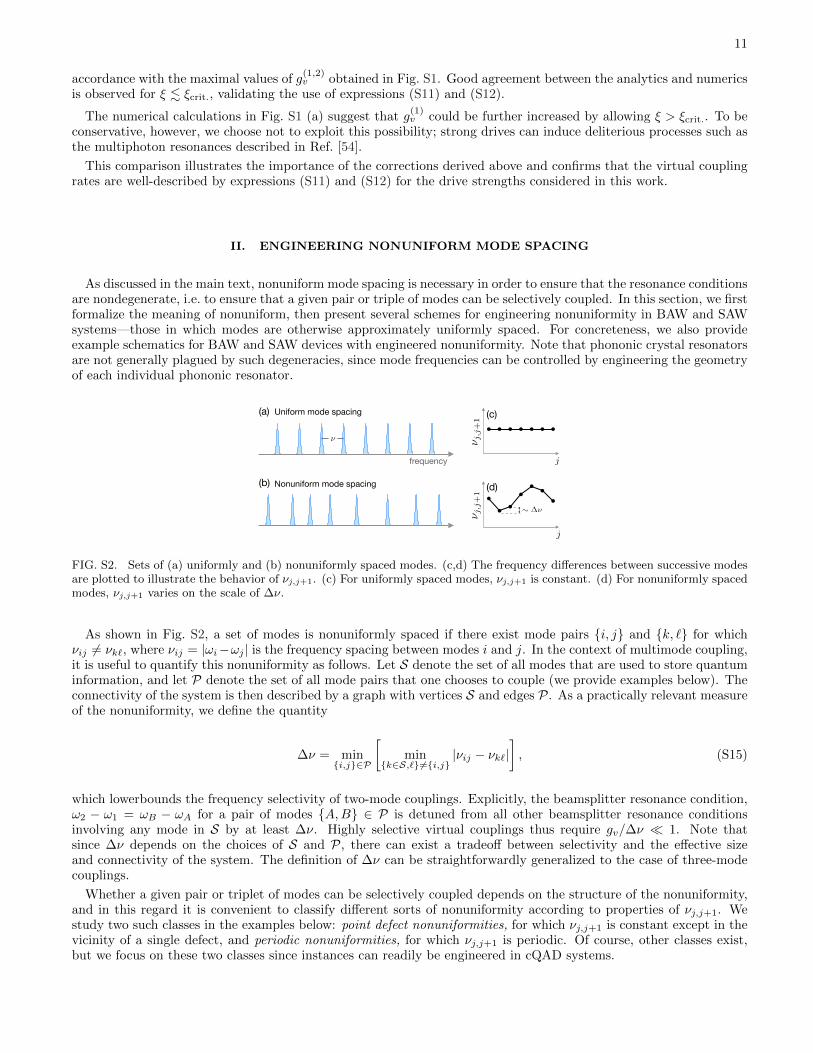
FIG. S2. Sets of (a) uniformly and (b) nonuniformly spaced modes. (c,d) The frequency differences between successive modesare plotted to illustrate the behavior of νj,j+1. (c) For uniformly spaced modes, νj,j+1 is constant. (d) For nonuniformly spacedmodes, νj,j+1 varies on the scale of ∆ν.
As shown in Fig. S2, a set of modes is nonuniformly spaced if there exist mode pairs i, j and k, ` for whichνij 6= νk`, where νij = |ωi−ωj | is the frequency spacing between modes i and j. In the context of multimode coupling,it is useful to quantify this nonuniformity as follows. Let S denote the set of all modes that are used to store quantuminformation, and let P denote the set of all mode pairs that one chooses to couple (we provide examples below). Theconnectivity of the system is then described by a graph with vertices S and edges P. As a practically relevant measureof the nonuniformity, we define the quantity
∆ν = mini,j∈P
[min
k∈S,`6=i,j|νij − νk`|
], (S15)
which lowerbounds the frequency selectivity of two-mode couplings. Explicitly, the beamsplitter resonance condition,ω2 − ω1 = ωB − ωA for a pair of modes A,B ∈ P is detuned from all other beamsplitter resonance conditionsinvolving any mode in S by at least ∆ν. Highly selective virtual couplings thus require gv/∆ν 1. Note thatsince ∆ν depends on the choices of S and P, there can exist a tradeoff between selectivity and the effective sizeand connectivity of the system. The definition of ∆ν can be straightforwardly generalized to the case of three-modecouplings.
Whether a given pair or triplet of modes can be selectively coupled depends on the structure of the nonuniformity,and in this regard it is convenient to classify different sorts of nonuniformity according to properties of νj,j+1. Westudy two such classes in the examples below: point defect nonuniformities, for which νj,j+1 is constant except in thevicinity of a single defect, and periodic nonuniformities, for which νj,j+1 is periodic. Of course, other classes exist,but we focus on these two classes since instances can readily be engineered in cQAD systems.
12
A. External mode hybridization
A point defect nonuniformity can be created by coupling the phonons to some external mode, such as a microwaveresonator. As demonstrated in Ref. [45], and sketched in Fig. S3(a,b), the resulting mode hybridization can significantlyshift phonon mode frequencies within some bandwidth D of the external mode. The nonuniformity ∆ν is dictated bythe magnitude of these frequency shifts. For example, frequency shifts of order 1MHz were demonstrated in Ref. [45].
This class of nonuniformity can enable selective coupling: selective two-mode coupling is possible if one or bothinvolved modes lie in D, and selective three-mode coupling is possible if two of the three involved modes lie in D.Hence, the set S can include arbitrarily many modes, but the set P can only include mode pairs with at least onemode in D. While modes outside of D cannot be directly coupled to one another, information from these modes caninstead be swapped into modes in D, manipulated, and swapped back. Note that the coherence of the external modeshould be comparable to that of the phonons, lest the hybridization result in a significant increase in effective decayrates, and in general there may exist a tradeoff between increased nonuniformity and enhanced decay.
j
ωj+1-
ωj
Hybridization with external mode
frequency
(a) (b)
Composite resonator(e) (f)
BAC
Two mode families(c) (d)
12
A B C
j
ωj+1-
ωj
A B C
D
S
S
j
j,j
+1
j
j,j
+1
j
j,j
+1
FIG. S3. Nonuniform mode spacing. (a) External mode hybridization. The coupling between phonons and an external modecauses strongly hybridized modes (dark blue) to deviate from the otherwise uniform spacing (dashed lines). The arrows showexamples of how this nonuniformity gives rise to nondegenerate resonance conditions: modes A and B can be coupled by theapplying drives indicated by solid arrows, while modes A, B, and C can be coupled by applying the drive indicated by thedashed arrow. (b) Frequency differences shrink significantly within a bandwidth D of the external mode. (c) Two mode families.Simultaneously coupling the transmon to two mode families (blue, green) enables selective two-mode coupling between modesfrom different families. Selectivity is only guaranteed in a finite region S, and an example of such a region is highlighted in (d).The use of an external mode C enables selective three-mode coupling. (e) Composite resonator. Nonuniform mode spacing incomposite resonators arises due to partial reflections at the interface(s). For example, with a single interface, a simple transfermatrix treatment [58] reveals that the FSR is periodically modulated, as in (f). Selective three-mode coupling can be enabledby restricting the transmon phonon-coupling bandwidth (regions with negligible coupling are shaded in gray), or by using anexternal mode as in (c).
B. Two phonon mode families
Another approach is to create a periodic nonuniformity by simultaneously coupling the transmon to two families ofphonon modes [18] with different free spectral ranges (FSRs). While modes within each family are uniformly spaced,the FSR difference causes the spacing between modes from different families to vary, as shown in Fig. S3(c,d). Thisnonuniformity enables two modes from different families to be selectively coupled, but because of the periodicity,selectivity is only guaranteed over a finite bandwidth smaller than one period. With two mode families, a set Scontaining ≈ ν/∆ν modes can be found wherein any two modes from different families can be selectively coupled with∆ν = |ν1 − ν2|, where ν1,2 are the FSRs of the two families.
By itself, the use of two mode families does not enable selective three-mode coupling [75], but this limitation can becircumvented by coupling the transmon to one or more external modes. For example, the BAW devices of Refs [16, 17]are housed in microwave cavities, and coupling the transmon to a high-Q cavity mode can enable selective three-modecoupling between the cavity and any pair of modes in S. In a SAW device, the additional mode could come fromanother SAW resonator or a microwave resonator. The transmon itself could even serve as the external mode, but
13
gate fidelities would then be directly limited by transmon coherence. Ideally, the coherence of the external modeshould be comparable to that of the phonons, lest it limit gate fidelity.
C. Composite resonators
Yet another approach is to employ a composite acoustic resonator, in which phonons propagate in media withdifferent indices of refraction [Fig. S3(e,f)]. Reflections at the interfaces can give rise to a periodic modulation of theFSR [58]. As in the case of two mode families, this periodic nonuniformity can enable selective two-mode couplingwithin a finite bandwidth S, though the magnitudes of both S and ∆ν depend on the nature of the modulation.
Whether selective three-mode coupling within S is feasible depends on the of the specific nature of the FSRmodulation. In cases where it is not already possible, selective three-mode coupling can be enabled by either couplingthe transmon to some external mode, as previously described, or alternatively by restricting the bandwidth over whichthe transmon-phonon coupling is appreciable. For example, if the transmon-phonon coupling is only appreciable withinS, as in Fig. S3(e), then selective three-mode coupling is possible since the system contains an effectively finite numberof nonuniformly spaced modes. In SAW systems, the coupling bandwidth can be tuned by changing the number offingers in the interdigitated transducer [19, 42, 76]. In BAW systems, the coupling bandwidth can be similarly tunedby changing the electromechanical transducer’s geometry. For instance, in a transducer comprised of alternating layersof piezoelectric and non-piezoelectric materials, the spacing, thickness, and number of such layers could be chosen sothat the coupling has a narrow response centered at a particular frequency, as in a Bragg reflector.
D. Example schematics
CPWmicrowave cavity
(c)(a)transducers
frequency
(b) (d)
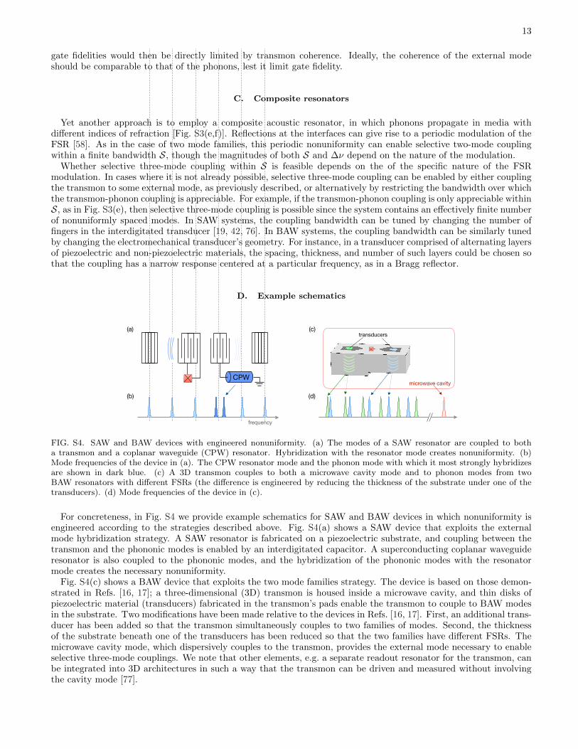
FIG. S4. SAW and BAW devices with engineered nonuniformity. (a) The modes of a SAW resonator are coupled to botha transmon and a coplanar waveguide (CPW) resonator. Hybridization with the resonator mode creates nonuniformity. (b)Mode frequencies of the device in (a). The CPW resonator mode and the phonon mode with which it most strongly hybridizesare shown in dark blue. (c) A 3D transmon couples to both a microwave cavity mode and to phonon modes from twoBAW resonators with different FSRs (the difference is engineered by reducing the thickness of the substrate under one of thetransducers). (d) Mode frequencies of the device in (c).
For concreteness, in Fig. S4 we provide example schematics for SAW and BAW devices in which nonuniformity isengineered according to the strategies described above. Fig. S4(a) shows a SAW device that exploits the externalmode hybridization strategy. A SAW resonator is fabricated on a piezoelectric substrate, and coupling between thetransmon and the phononic modes is enabled by an interdigitated capacitor. A superconducting coplanar waveguideresonator is also coupled to the phononic modes, and the hybridization of the phononic modes with the resonatormode creates the necessary nonuniformity.
Fig. S4(c) shows a BAW device that exploits the two mode families strategy. The device is based on those demon-strated in Refs. [16, 17]; a three-dimensional (3D) transmon is housed inside a microwave cavity, and thin disks ofpiezoelectric material (transducers) fabricated in the transmon’s pads enable the transmon to couple to BAW modesin the substrate. Two modifications have been made relative to the devices in Refs. [16, 17]. First, an additional trans-ducer has been added so that the transmon simultaneously couples to two families of modes. Second, the thicknessof the substrate beneath one of the transducers has been reduced so that the two families have different FSRs. Themicrowave cavity mode, which dispersively couples to the transmon, provides the external mode necessary to enableselective three-mode couplings. We note that other elements, e.g. a separate readout resonator for the transmon, canbe integrated into 3D architectures in such a way that the transmon can be driven and measured without involvingthe cavity mode [77].
14
III. DETAILED DESCRIPTION OF THE CQAD QRAM
In this section we provide a more complete description of the qRAM proposed in the main text. The operation ofthe quantum quantum routers is first discussed in detail, and then schemes for extracting data from either a classicalor a quantum database are presented.
A. Operation of a quantum router
During a qRAM query, the operation of each quantum router can be divided ino four stages: initialization, down-stream routing, upstream routing, and extraction. In the initialization stage [Fig. S5(a)], an incoming address qubitin the top mode is stored in the routing mode at the vertex so that it can control the routing of subsequent qubits.Initialization is performed simply by swapping the states of the top and routing modes. In the downstream routingstage [Fig. S5(b)], the router directs incoming qubits to one of two output modes conditioned on the state of theaddress qubit. As shown in the corresponding circuit, this routing operation can be implemented using a SWAP gateand a controlled-SWAP gate. Note that the action of the controlled-SWAP gate is trivial when the routing qubit is in|0〉. Similarly, the action of the SWAP gate is trivial when the routing qubit is in |1〉, since the affected modes are bothin |0〉 after the controlled-SWAP has been performed.
Once all downstream routing is complete and the data has been transferred to the bus, the inverse operations(upstream routing and extraction) must be performed in order to disentangle the address and bus qubits from therouters. Both the SWAP and controlled-SWAP unitaries are their own inverses, so the upstream routing [Fig. S5(c)] andextraction [Fig. S5(d)] operations can be implemented by time-reversing the downstream routing and initializationoperations, respectively.
FIG. S5. Quantum router operation. (a) Initialization. An incoming address qubit |φ〉 is swapped into the routing mode. (b)Downstream routing. An incoming qubit |ψ〉 is routed to the left(right) when the address qubit is in |0〉(|1〉). (c) Upstreamrouting. The router directs a qubit from either the right or left mode into the top mode conditioned on the state of the addressqubit. (d) Extraction. The address qubit is swapped into the top mode so that it can be routed back out of the tree.
B. Database access schemes
In a qRAM, the address and bus registers must necessarily be composed of qubits. However, the database itselfcan contain either classical or quantum data, depending on the intended application. How the database is accesseddepends on the type of data. In the classical case, data can be directly copied into the bus, but in the quantum casethe no-cloning theorem prevents one from copying quantum data. Instead, the bus can be entangled or swapped withthe data, which generally leaves the address-bus system entangled with the database after a query. Additionally, whilea qRAM should in general be able to both read from and write to the database, in many applications a quantumread-only memory (qROM) is sufficient [78–80]. This reduced functionality can be used to simplify the database accessscheme. Below we present schemes for reading and writing both quantum and classical data, as well as a simplifiedscheme for read-only classical data.
Figure S6 illustrates procedures for accessing classical and quantum databases. To read quantum data from thedatabase [Fig. S6(a)], we introduce a so-called pointer qubit, initially prepared in the state |1〉. The purpose of thisqubit is to indicate which database entries should be extracted. After all address qubits have been routed into place,the pointer qubit follows their path to the bottom of the tree. Modes at the bottom of the tree then serve as controls
15
|1i
|0i
|0i
|1i
|+i
|1i
|0i
|0i
|1i
|+i
|1i
|0i
|0i
|1i
|i
|1i
|0i
|0i
|1i
|1i
|1i
|0i
|0i
|1i
|1i
|1i
|0i
|0i
|1i
|1i
Route in pointer qubit Controlled SWAPs extract data qubit
Extract data, pointer, and address qubits
Route in bus qubit CZ operations copy data bit Extract bus, address qubitsCla
ssic
al d
atab
ase
Qua
ntum
dat
abas
e
| 0i | 1i | 0i | 1i | 0i
| 1i
|1i
|0i
|0i
0 1
|1i
|+i
|1i
|0i
|0i
0 1
|1i
|+i|0i |0i
|1i
|0i
|0i
0 1
|1i
|i
Route in bus qubitApply phase shifts conditioned
on classical dataExtract bus, address qubitsC
lass
ical
dat
abas
e (r
ead-
only
)
|0i |1i|0i |1i
(a)
(b)
(c)
|0i |1i
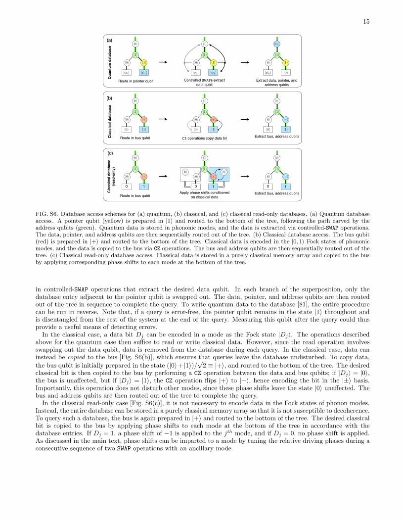
FIG. S6. Database access schemes for (a) quantum, (b) classical, and (c) classical read-only databases. (a) Quantum databaseaccess. A pointer qubit (yellow) is prepared in |1〉 and routed to the bottom of the tree, following the path carved by theaddress qubits (green). Quantum data is stored in phononic modes, and the data is extracted via controlled-SWAP operations.The data, pointer, and address qubits are then sequentially routed out of the tree. (b) Classical database access. The bus qubit(red) is prepared in |+〉 and routed to the bottom of the tree. Classical data is encoded in the |0, 1〉 Fock states of phononicmodes, and the data is copied to the bus via CZ operations. The bus and address qubits are then sequentially routed out of thetree. (c) Classical read-only database access. Classical data is stored in a purely classical memory array and copied to the busby applying corresponding phase shifts to each mode at the bottom of the tree.
in controlled-SWAP operations that extract the desired data qubit. In each branch of the superposition, only thedatabase entry adjacent to the pointer qubit is swapped out. The data, pointer, and address qubits are then routedout of the tree in sequence to complete the query. To write quantum data to the database [81], the entire procedurecan be run in reverse. Note that, if a query is error-free, the pointer qubit remains in the state |1〉 throughout andis disentangled from the rest of the system at the end of the query. Measuring this qubit after the query could thusprovide a useful means of detecting errors.
In the classical case, a data bit Dj can be encoded in a mode as the Fock state |Dj〉. The operations describedabove for the quantum case then suffice to read or write classical data. However, since the read operation involvesswapping out the data qubit, data is removed from the database during each query. In the classical case, data caninstead be copied to the bus [Fig. S6(b)], which ensures that queries leave the database undisturbed. To copy data,
the bus qubit is initially prepared in the state (|0〉+ |1〉)/√
2 ≡ |+〉, and routed to the bottom of the tree. The desiredclassical bit is then copied to the bus by performing a CZ operation between the data and bus qubits; if |Dj〉 = |0〉,the bus is unaffected, but if |Dj〉 = |1〉, the CZ operation flips |+〉 to |−〉, hence encoding the bit in the |±〉 basis.Importantly, this operation does not disturb other modes, since these phase shifts leave the state |0〉 unaffected. Thebus and address qubits are then routed out of the tree to complete the query.
In the classical read-only case [Fig. S6(c)], it is not necessary to encode data in the Fock states of phonon modes.Instead, the entire database can be stored in a purely classical memory array so that it is not susceptible to decoherence.To query such a database, the bus is again prepared in |+〉 and routed to the bottom of the tree. The desired classicalbit is copied to the bus by applying phase shifts to each mode at the bottom of the tree in accordance with thedatabase entries. If Dj = 1, a phase shift of −1 is applied to the jth mode, and if Dj = 0, no phase shift is applied.As discussed in the main text, phase shifts can be imparted to a mode by tuning the relative driving phases during aconsecutive sequence of two SWAP operations with an ancillary mode.


![Yiwen Hua , Pritish , Saravana , and arXiv:2003.11172v1 ... · Holopix50k: A Large-Scale In-the-wild Stereo Image Dataset Yiwen Hua[0000 0003 2334 7157], Puneet Kohli[0000 0002 4817](https://static.documents.pub/doc/80x56/5f89872fdddb812f8122e639/yiwen-hua-pritish-saravana-and-arxiv200311172v1-holopix50k-a-large-scale.jpg)

![HOLOGRAPHY, QUANTUM GEOMETRY, AND QUANTUM INFORMATION THEORY · The emerging fields of quantum computation [22], quantum communication and quantum cryptography [23], quantum dense](https://static.documents.pub/doc/80x56/5ec76f6b603b2e345706bd5a/holography-quantum-geometry-and-quantum-information-theory-the-emerging-fields.jpg)

