For RoHS Inquiries:CommScope Inc.Corke Abbey, BrayCo. Dublin, IrelandAttn: Legal Department
Page 1 of 6
General
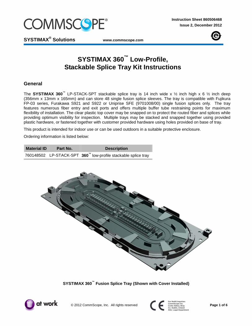
The SYSTIMAX 360™ LP-STACK-SPT stackable splice tray is 14 inch wide x ½ inch high x 6 ½ inch deep (356mm x 13mm x 165mm) and can store 48 single fusion splice sleeves. The tray is compatible with Fujikura FP-03 series, Furakawa S921 and S922 or Uniprise SFE (9701008/00) single fusion splices only. The tray features numerous fiber entry and exit ports and offers multiple buffer tube restraining points for maximum flexibility of installation. The clear plastic top cover may be snapped on to protect the routed fiber and splices while providing optimum visibility for inspection. Multiple trays may be stacked and snapped together using provided plastic hardware, or fastened together with customer provided hardware using holes provided on base of tray.
This product is intended for indoor use or can be used outdoors in a suitable protective enclosure.
Ordering information is listed below:
Material ID Part No. Description 760148502 LP-STACK-SPT 360™ low-profile stackable splice tray
SYSTIMAX 360™ Fusion Splice Tray (Shown with Cover Installed)
860506468 Instruction Sheet
www.commscope.com
Page 2 of 6
How to Contact Us
• To find out more about CommScope® products, visit us on the web at http://www.commscope.com/
• For technical assistance:
- Within the United States, contact your local account representative or technical support at 1-800-344-0223. Outside the United States, contact your local account representative or Authorized Business Partner.
- Within the United States, report any missing/damaged parts or any other issues to CommScope Customer Claims at 1-866-539-2795. Outside the United States, contact your local account representative or Authorized Business Partner.
• Disconnected optical components may emit invisible optical radiation that can damage your eyes. Never look directly into an optical component that may have a laser coupled to it. Serious and permanent retinal damage is possible. If accidental exposure to laser radiation is suspected, consult a physician for an eye examination.
• Wearing safety glasses during installation of this shelf is recommended. Although standard safety glasses provide no protection from potential optical radiation, they offer protection from accidental airborne hardware and cleaning solvents.
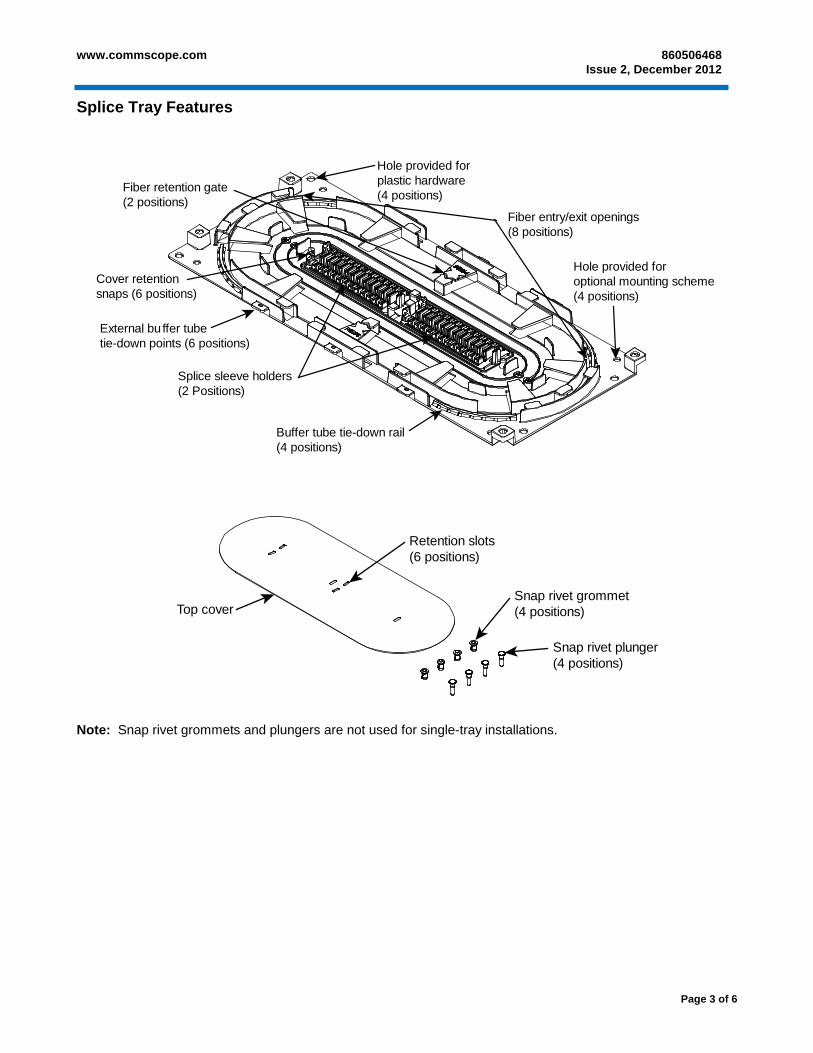
External bu ffer tubetie-down points (6 positions)
Cover retentionsnaps (6 positions)
Fiber retention gate(2 positions)
Retention slots(6 positions)
Top coverSnap rivet grommet(4 positions)
Snap rivet plunger(4 positions)
Note: Snap rivet grommets and plungers are not used for single-tray installations.
860506468 Instruction Sheet
www.commscope.com
Page 4 of 6
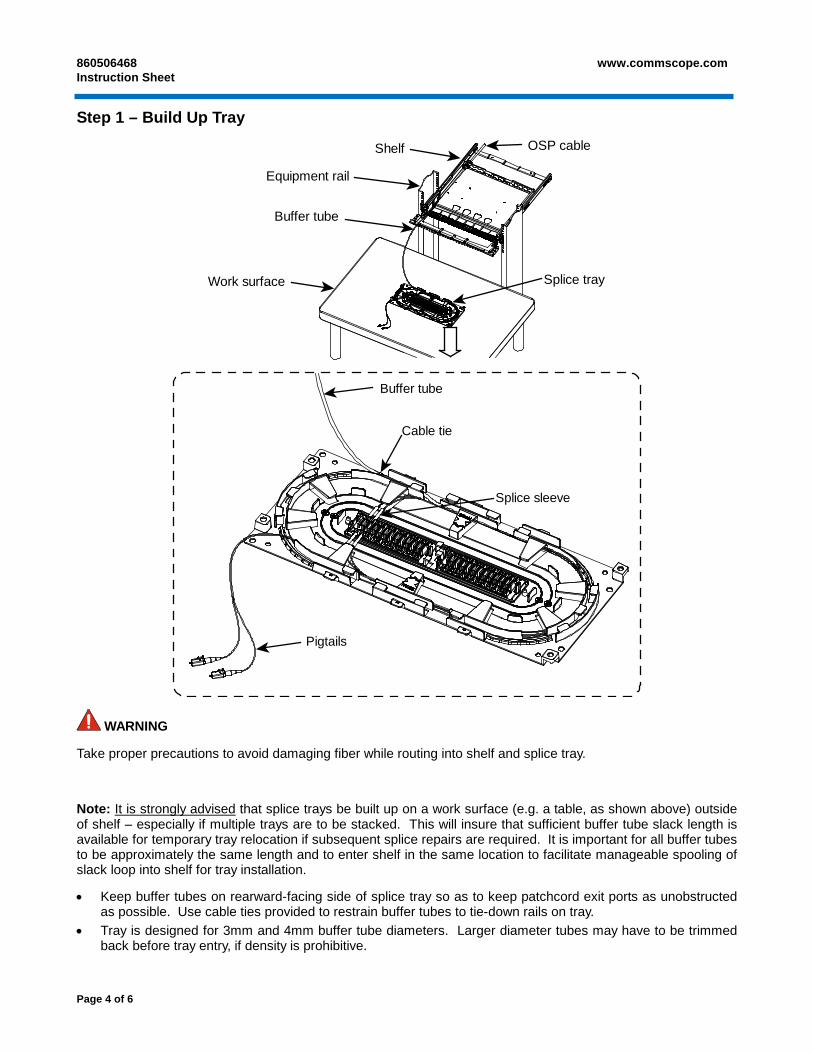
Step 1 – Build Up Tray
Shelf
Equipment rail
Buffer tube
Work surface
OSP cable
Splice tray
Buffer tube
Cable tie
Pigtails
Splice sleeve
WARNING
Take proper precautions to avoid damaging fiber while routing into shelf and splice tray.
Note: It is strongly advised
• Keep buffer tubes on rearward-facing side of splice tray so as to keep patchcord exit ports as unobstructed as possible. Use cable ties provided to restrain buffer tubes to tie-down rails on tray.
that splice trays be built up on a work surface (e.g. a table, as shown above) outside of shelf – especially if multiple trays are to be stacked. This will insure that sufficient buffer tube slack length is available for temporary tray relocation if subsequent splice repairs are required. It is important for all buffer tubes to be approximately the same length and to enter shelf in the same location to facilitate manageable spooling of slack loop into shelf for tray installation.
• Tray is designed for 3mm and 4mm buffer tube diameters. Larger diameter tubes may have to be trimmed back before tray entry, if density is prohibitive.
www.commscope.com 860506468 Issue 2, December 2012
Page 5 of 6
• Splice tray is sized to contain up to 1 meter (39”) each of pigtail fiber and fiber from the OSP cable. • 40mm splice protector sleeves are recommended when using 900 micron fiber from OSP cable. As tray fills
up with fiber, it may become difficult to maintain proper bend radii at splices when using 60mm sleeves. • Install splice sleeves into lower position of holders by firmly pressing them down into retention features with 2
index fingers. One finger is sufficient for placing sleeves into the upper (stacked) position. Use and orange stick or similar device to remove sleeves for repairs. Press down on holder to support it when removing a splice sleeve.
• Wind patchcord groups in opposite directions (clockwise & counter-clockwise) inside tray to keep lengths exiting tray consistent for better dressing at termination. Use Millie-ties to bundle and restrain pigtails, as required.
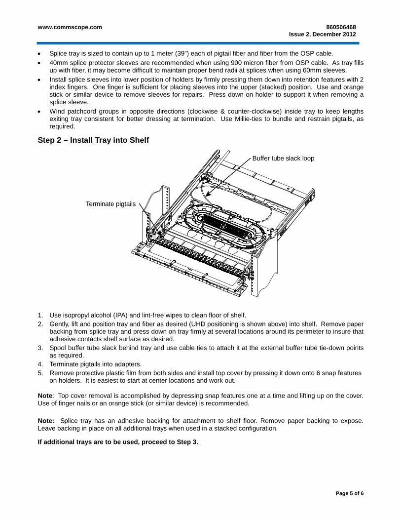
Step 2 – Install Tray into Shelf
Buffer tube slack loop
Terminate pigtails
1. Use isopropyl alcohol (IPA) and lint-free wipes to clean floor of shelf. 2. Gently, lift and position tray and fiber as desired (UHD positioning is shown above) into shelf. Remove paper
backing from splice tray and press down on tray firmly at several locations around its perimeter to insure that adhesive contacts shelf surface as desired.
3. Spool buffer tube slack behind tray and use cable ties to attach it at the external buffer tube tie-down points as required.
4. Terminate pigtails into adapters. 5. Remove protective plastic film from both sides and install top cover by pressing it down onto 6 snap features
on holders. It is easiest to start at center locations and work out.
Note: Top cover removal is accomplished by depressing snap features one at a time and lifting up on the cover. Use of finger nails or an orange stick (or similar device) is recommended. Note: Splice tray has an adhesive backing for attachment to shelf floor. Remove paper backing to expose. Leave backing in place on all additional trays when used in a stacked configuration.
If additional trays are to be used, proceed to Step 3.
860506468 Instruction Sheet
www.commscope.com
Page 6 of 6
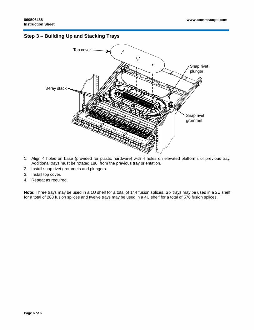
Step 3 – Building Up and Stacking Trays
Top cover
3-tray stack
Snap rivetplunger
Snap rivetgrommet
1. Align 4 holes on base (provided for plastic hardware) with 4 holes on elevated platforms of previous tray.
Additional trays must be rotated 180° from the previous tray orientation. 2. Install snap rivet grommets and plungers. 3. Install top cover. 4. Repeat as required.
Note: Three trays may be used in a 1U shelf for a total of 144 fusion splices. Six trays may be used in a 2U shelf for a total of 288 fusion splices and twelve trays may be used in a 4U shelf for a total of 576 fusion splices.


![Untitled-1 [preformed.com]preformed.com/images/pdfs/Communications/Fiber_Networks/...Buffer Tube Retainer Clips Shell Supporters (not shown) Splice Tray Splice Retainer Block Splice](https://static.documents.pub/doc/80x56/60ec7b50d1427246717b3904/untitled-1-buffer-tube-retainer-clips-shell-supporters-not-shown-splice.jpg)


