TFSI Kit Thank you for choosing the Syvecs TFSI Kit IMPORTANT: This Kit is designed to only work with the TFSI Engine range not on the Newer TSI Engines The kit should come with the following: 1 x Syvecs GDI4 Ecu 1 x TFSI Wiring Loom with External 4 Port Injector wires Installation 1.) Remove the Negative Terminal from the battery on the Vehicle 2.) Remove the OEM Engine control modules found under the front window compartment of the engine bay or under the Electronics Box. 3.) If wanting to control additional injectors these can be wired into the 12way Delphi break out connector found coming out of the Syvecs Ecu – Pinouts found below 4.) Replace the battery terminal and engine covers and proceed to the Syvecs Manual
Transcript
TFSI Kit
Thank you for choosing the Syvecs TFSI Kit
IMPORTANT: This Kit is designed to only work with the TFSI Engine range not on the Newer TSI Engines
The kit should come with the following:
1 x Syvecs GDI4 Ecu
1 x TFSI Wiring Loom with External 4 Port Injector wires
Installation
1.) Remove the Negative Terminal from the battery on the Vehicle
2.) Remove the OEM Engine control modules found under the front window compartment of the engine bay or under the Electronics Box.
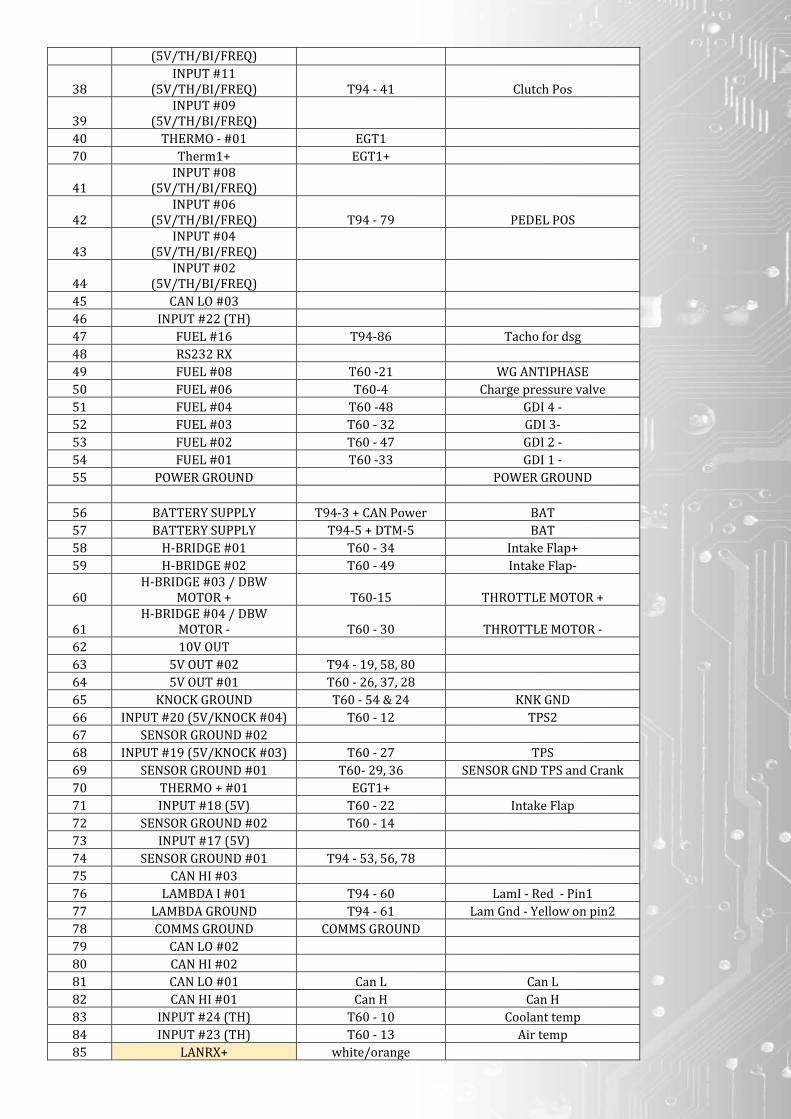
3.) If wanting to control additional injectors these can be wired into the 12way Delphi break out connector found coming out of the Syvecs Ecu – Pinouts found below
4.) Replace the battery terminal and engine covers and proceed to the Syvecs Manual
Ryan
Stamp
TFSI Specific Software Options
Due to the huge number of Cars that the TFSI Engine is fitted to, an ECU Coding setup needs adjusting in Scal to suit the model of your VAG Group Car.
This is found at the bottom under I/O Configuration
Car Coding1 Values
Audi ‐ 0 Golf Mk5 ‐ 84 Seat Leon ‐ 168 Golf R ‐ 248
Seat Leon DSG ‐ 330 Skoda TSI Manual ‐ 415 Audi TT DSG 2WD ‐ 500 Golf R UK MK6 ‐ 580 Skoda DSG ‐ 690
Golf R MK6 China ‐ 760 Polo WRC – 850 Golf 6 GTI ‐ 940
Audi 8P S3 - 1024Scirocco - 1100
Car Coding2 Values
Audi ‐ 0 Golf Mk5 ‐ 84 Seat Leon ‐ 168 Golf R ‐ 248
Seat Leon DSG ‐ 330 Skoda TSI Manual ‐ 415 Audi TT DSG 2WD ‐ 500 Golf R UK MK6 ‐ 580 Skoda DSG ‐ 690
Golf R MK6 China ‐ 760 Polo WRC – 850 Golf 6 GTI ‐ 940
Audi 8P S3 - 1024Scirocco - 1100
Sensors ‐ LoadCell3 ‐ Default Value ‐ is Gearbox Type
Manual ‐ 0 DSG ‐ 1
Injector Size is set in Fuel Consumption – Injector Consumption Scaling
This value is important. Must be set correct for Torque Estimation on DSG Cars
Injector Size / 60 = ml/s value
OEM DI Injectors are set in the Base map @ 15ml/s
TFSI Kit FAQ and Help
Q) Does the TFSI kit come with 4 External injector loom?
A) The Kit comes with a 6way DTM Connector that has the 4 External Injectors and 12v present for allowing wiring for the additional injectors
Q) Can I install different in tank pump?
A) Yes, the Syvec’s communicates with the OEM Fuel Pump Ecu to allow PWM Control of the Pump so it can be adjusted to suit your new pump.
Q) What of the original features will now now work?
A) None, even cruise control works but it doesn’t allow you to adjust speed on the stalk, only clamp a speed
Q) Can we use the OBD port still to Log, Read Codes and Clear them on other ecus on the car like ABS?
A) Yes via the Use on VagCom
Q) How is the Fuel Mapping done in Scal
A) On the Secondary injection map – The base map is 4D tuned as MAP1 is before the TPS as default on engine. Uses Secondary Multipler Under Run‐Mode Fueling and
Simple Manifold Pressure under Run‐Mode Fueling – Corrections
Q) How do I setup Additional Port Injectors
A) You first need to assign them in the I/O Config Pin assignment and Program ecu.
After you need to set the Secondary multipler difference between the DI and Port under Run mode fueling – Correction – Secondary Multipler
OEM DI Injectors flow around 650cc.. So do 650 / (Port Injectors cc) to give a good starting point on Secondary multiplier
Ensure that the Secondary Injection Opening Time values are correct from your manufacture.
After Start the engine up and monitor the Lambda1 Value and FuelMltCll1 Value. Now go to Injector Split1 and increase the values up to 50% in the area and around
that the tracer is showing the engine is current at.
As the Ports start to blend in and you have the Split at 50% you need to be monitoring the Lambda1 and FuelmltCll1. If the values are different compared to before
when split was at 0% then adjust the Secondary multiplier live until they are the same with the split present.. Once that is good, set the Split back to 0%,
When the OEM DI Injectors now reach their limit the Syvecs ecu will automatically bring the ports in to maintain the desired fuel requirements, If you wish to bring the
port injectors in sooner then set the split table as required.


![Directshift gearboxDQ500. Its first use was in the Audi TTRS.[13] Audi longitudinal DSG. 8/7/2015 Directshift gearbox Wikipedia, the free encyclopedia ... 2009, it is only used in](https://static.documents.pub/doc/80x56/60b567008de58401f27e4cb4/directshift-gearbox-dq500-its-first-use-was-in-the-audi-ttrs13-audi-longitudinal.jpg)

