67
T-110.5111 Computer Networks II Wireless Local Area networks 06.10.2014 Matti Siekkinen

• 23.9.2010
T-110.5111 Computer Networks II Wireless Local Area networks 06.10.2014 Matti Siekkinen

Outline
• The big picture • (Re)view of basic concepts in wireless communication
– Wireless channels – PHY and MAC layer techniques
• IEEE 802.11 Wireless LAN, a.k.a. Wi-Fi – PHY – MAC – Some enhancements
• Conclusions

The big picture: Wireless networks and standards
• 3
WPAN
WLAN
WMAN
WWAN 3GPP/3GPP2: GSM, CDMA2000, UMTS, LTE
IEEE 802.20 (iBurst)
IEEE 802.15 (Bluetooth, ZigBee, ...)
IEEE 802.11 (Wi-Fi)
IEEE 802.16 (WiMax)
What’s the difference?
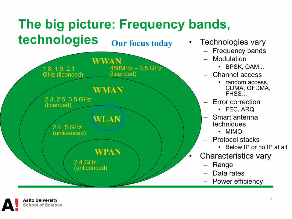
The big picture: Frequency bands, technologies • Technologies vary
– Frequency bands – Modulation
• BPSK, QAM... – Channel access
• random access, CDMA, OFDMA, FHSS…
– Error correction • FEC, ARQ
– Smart antenna techniques
• MIMO – Protocol stacks
• Below IP or no IP at all • Characteristics vary
– Range – Data rates – Power efficiency
• 4
WPAN
WLAN
WMAN
WWAN 450MHz – 3.5 GHz (licenced)
1.8, 1.9, 2.1 GHz (licenced)
2.4 GHz (unlicenced)
2.4, 5 GHz (unlicenced)
2.3, 2.5, 3.5 GHz (licenced)
Our focus today
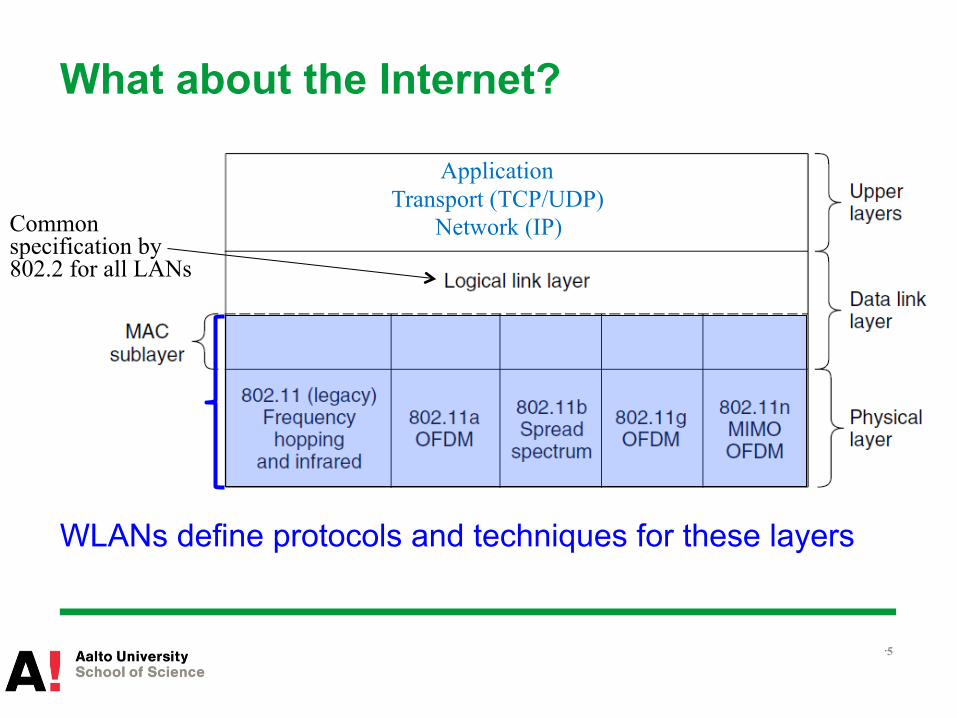
What about the Internet?
WLANs define protocols and techniques for these layers
• 5
Application Transport (TCP/UDP)
Network (IP) Common specification by 802.2 for all LANs
Outline
• The big picture • (Re)view of basic concepts in wireless communication
– Wireless channels – PHY and MAC layer techniques
• IEEE 802.11 Wireless LAN, a.k.a. Wi-Fi – PHY – MAC – Some enhancements
• Conclusions
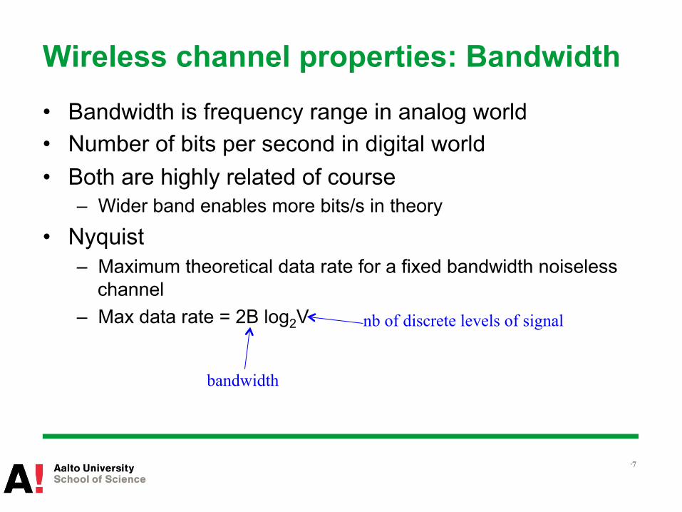
Wireless channel properties: Bandwidth • Bandwidth is frequency range in analog world • Number of bits per second in digital world • Both are highly related of course
– Wider band enables more bits/s in theory
• Nyquist – Maximum theoretical data rate for a fixed bandwidth noiseless
channel – Max data rate = 2B log2V
• 7
nb of discrete levels of signal
bandwidth
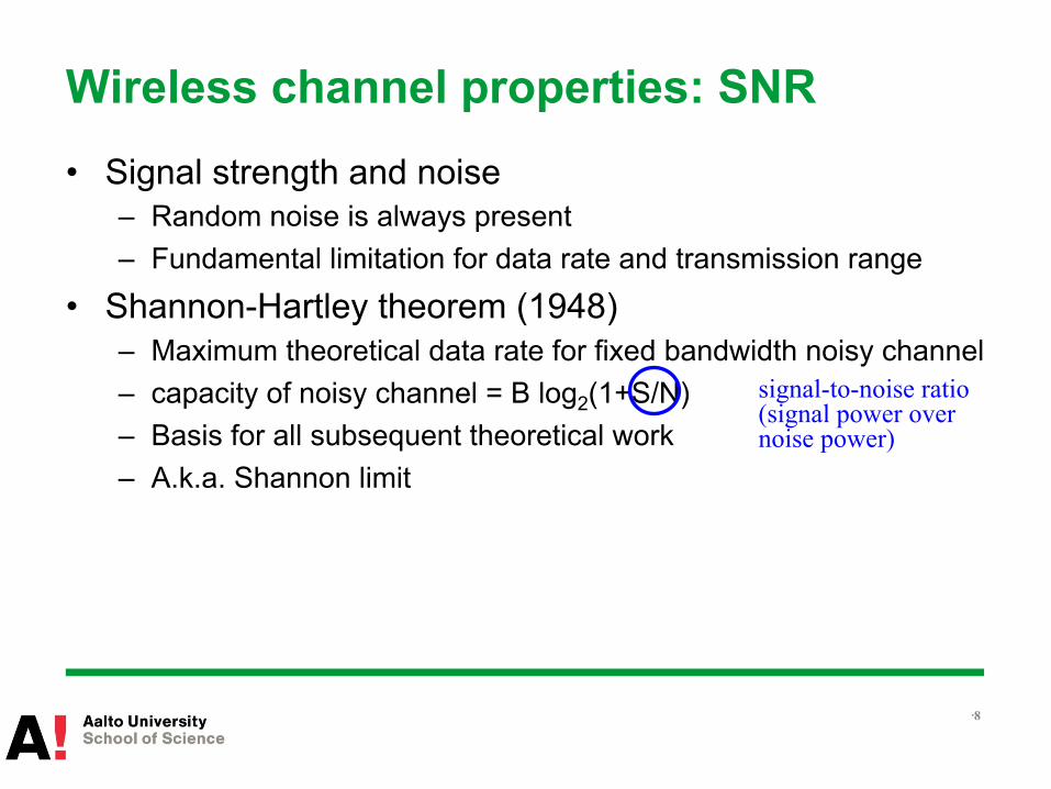
Wireless channel properties: SNR • Signal strength and noise
– Random noise is always present – Fundamental limitation for data rate and transmission range
• Shannon-Hartley theorem (1948) – Maximum theoretical data rate for fixed bandwidth noisy channel – capacity of noisy channel = B log2(1+S/N) – Basis for all subsequent theoretical work – A.k.a. Shannon limit
• 8
signal-to-noise ratio (signal power over noise power)
Quality of a wireless link
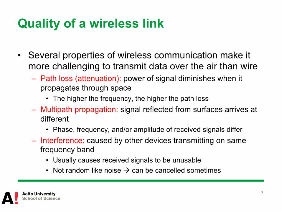
• Several properties of wireless communication make it more challenging to transmit data over the air than wire – Path loss (attenuation): power of signal diminishes when it
propagates through space • The higher the frequency, the higher the path loss
– Multipath propagation: signal reflected from surfaces arrives at different
• Phase, frequency, and/or amplitude of received signals differ – Interference: caused by other devices transmitting on same
frequency band • Usually causes received signals to be unusable • Not random like noise à can be cancelled sometimes
• 9

Outline
• The big picture • (Re)view of basic concepts in wireless communication
– Wireless channels – PHY and MAC layer techniques
• IEEE 802.11 Wireless LAN, a.k.a. Wi-Fi – PHY – MAC – Some enhancements
• Conclusions
Physical layer in wireless networks: Modulation • Digital modulation
– Code bits into a wireless analog signal – Vary amplitude, phase, or frequency of the carrier signal
according to bit sequence
• Basic digital modulation techniques – PSK: Phase-shift keying – FSK: Frequency-shift keying – ASK: Amplitude-shift keying – QAM: Quadrature amplitude modulation
• Combines amplitude and phase modulation
• 11

Physical layer in wireless networks: Modulation • Possible to use several discrete signal levels • Symbol rate = bits per symbol
– Basic (Binary) schemes use 1 bit per symbol • E.g. Binary PSK (BPSK)
– Quadrature schemes use 2 bits per symbol • E.g. Quadrature PSK (QPSK)
– Also QAM uses more bits per symbol • E.g. 4-QAM, 16-QAM, 64-QAM, 256-QAM…
• Tradeoff between rate and robustness – More bits per symbol à faster data rate – Less bits per symbol à more robust towards
noise
• 12
16-QAM example constellation
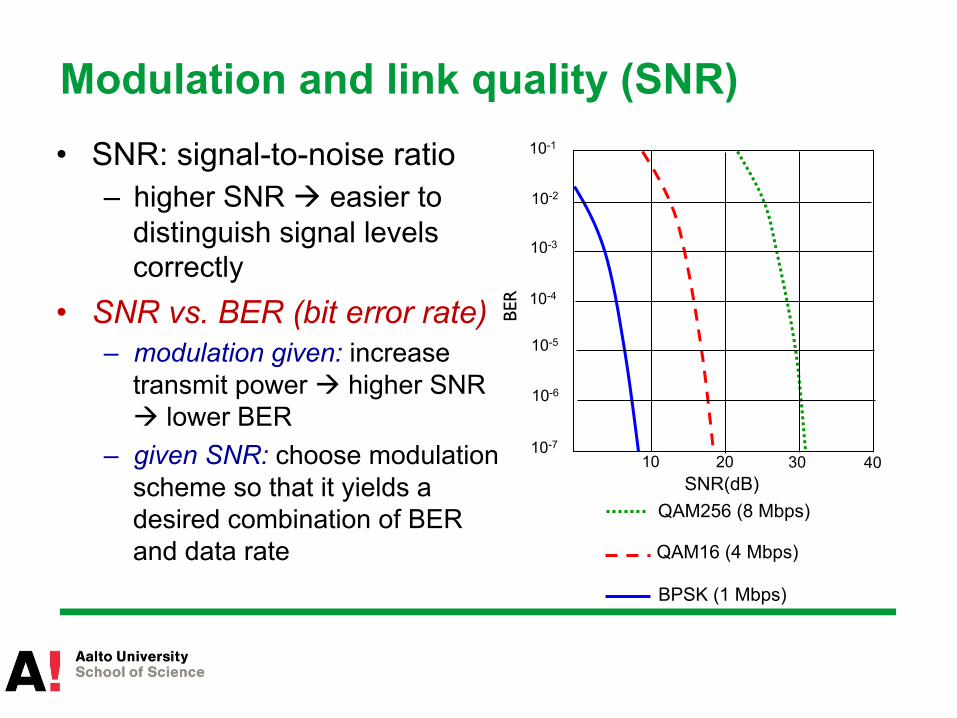
• SNR: signal-to-noise ratio – higher SNR à easier to
distinguish signal levels correctly
• SNR vs. BER (bit error rate) – modulation given: increase
transmit power à higher SNR à lower BER
– given SNR: choose modulation scheme so that it yields a desired combination of BER and data rate
10 20 30 40
QAM256 (8 Mbps)
QAM16 (4 Mbps)
BPSK (1 Mbps)
SNR(dB) BE
R
10-1
10-2
10-3
10-5
10-6
10-7
10-4
Modulation and link quality (SNR)

Physical layer in wireless networks: Multiplexing • Combine multiple signals into a single transmitted signal • Why used?
– Different reasons: better resilience (interference, noise), security – Several multiplexing techniques also used for multiple access
• Example: Frequency-hopping spread spectrum (FHSS) – Transmit over different frequencies by hopping rapidly from one
frequency to another – Follow a specific sequence of frequencies – E.g. Bluetooth uses this
• 14

Physical layer in wireless networks: Multiplexing
• OFDM: Orthogonal frequency-division multiplexing – Use multiple carrier frequencies – Orthogonal sub-carrier signals are
modulated using basic schemes (e.g. QAM)
– Narrowband channels less sensitive to noise and fading than single higher bw one
• Higher bandwidth à smaller duration for one transmitted bit à more susceptible to impulse noise
• Fading affects differently the different frequency components of a channel
• 15
orthogonality prevents interference between the signals

MAC layer in wireless networks
• What’s the job of multiple access protocols? – Multiple access protocols coordinate who gets to use the shared
channel at a given time instance
• Ideally: – Just one node à gets all the bandwidth – M nodes à each one gets 1/M of the total bandwidth
• Needed sometimes in wired networks as well
• 16
MAC layer in wireless networks
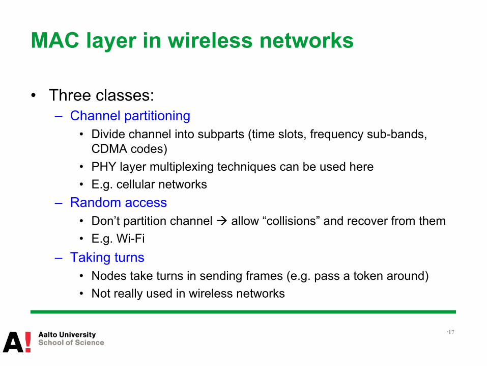
• Three classes: – Channel partitioning
• Divide channel into subparts (time slots, frequency sub-bands, CDMA codes)
• PHY layer multiplexing techniques can be used here • E.g. cellular networks
– Random access • Don’t partition channel à allow “collisions” and recover from them • E.g. Wi-Fi
– Taking turns • Nodes take turns in sending frames (e.g. pass a token around) • Not really used in wireless networks
• 17

Outline
• The big picture • (Re)view of basic concepts in wireless communication
– Wireless channels – PHY and MAC layer techniques
• IEEE 802.11 Wireless LAN, a.k.a. Wi-Fi – PHY – MAC – Some enhancements
• Conclusions

What is IEEE 802.11?
• Set of standards for Wireless Local Area Networks – Really a standard with a set of amendments
• Created and maintained by IEEE Standards Committee – IEEE (Institute of Electrical and Electronics Engineers) is non-
profit professional association
• Defines protocols and mechanisms mainly for – Physical layer – Medium access control (MAC)
• 19

What is Wi-Fi?
• “A certification mark developed by the Wi-Fi Alliance to indicate that wireless local area network (WLAN) products are based on the Institute of Electrical and Electronics Engineers' (IEEE) 802.11 standards.”
• Wi-Fi Alliance is a global non-profit industry association of hundreds of companies
• Wi-Fi certification – Interoperability and quality – Need to be member of the alliance to get your products
reviewed for certification
• 20

802.11: Overview of the many amendments PHY (.11, a, b, g, j, n, p, y, ac, ad, af, ah) • Change data rate options • Change spectrum
MAC • Security (i, w) • Measurement and Management (k, v) • Flow control and QoS (e, aa, ae) • Time required to establish connection (r, ai) • Spectral Efficiency • Regulatory behavior (d, h) • Radio node connection topology (s, z) • Connection with other networks (u)
• 21
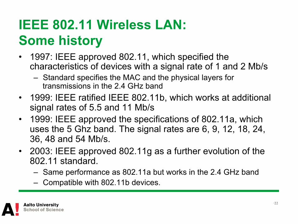
IEEE 802.11 Wireless LAN: Some history • 1997: IEEE approved 802.11, which specified the
characteristics of devices with a signal rate of 1 and 2 Mb/s – Standard specifies the MAC and the physical layers for
transmissions in the 2.4 GHz band • 1999: IEEE ratified IEEE 802.11b, which works at additional
signal rates of 5.5 and 11 Mb/s • 1999: IEEE approved the specifications of 802.11a, which
uses the 5 Ghz band. The signal rates are 6, 9, 12, 18, 24, 36, 48 and 54 Mb/s.
• 2003: IEEE approved 802.11g as a further evolution of the 802.11 standard. – Same performance as 802.11a but works in the 2.4 GHz band – Compatible with 802.11b devices.
• 22

Outline
• The big picture • (Re)view of basic concepts in wireless communication
– Wireless channels – PHY and MAC layer techniques
• IEEE 802.11 Wireless LAN, a.k.a. Wi-Fi – PHY – MAC – Some enhancements
• Conclusions
802.11 in practice: PHY
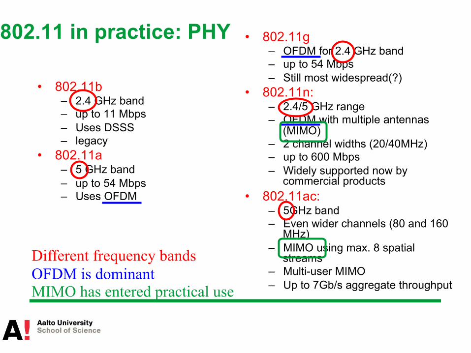
• 802.11b – 2.4 GHz band – up to 11 Mbps – Uses DSSS – legacy
• 802.11a – 5 GHz band – up to 54 Mbps – Uses OFDM
• 802.11g – OFDM for 2.4 GHz band – up to 54 Mbps – Still most widespread(?)
• 802.11n: – 2.4/5 GHz range – OFDM with multiple antennas
(MIMO) – 2 channel widths (20/40MHz) – up to 600 Mbps – Widely supported now by
commercial products • 802.11ac:
– 5GHz band – Even wider channels (80 and 160
MHz) – MIMO using max. 8 spatial
streams – Multi-user MIMO – Up to 7Gb/s aggregate throughput
OFDM is dominant Different frequency bands
MIMO has entered practical use
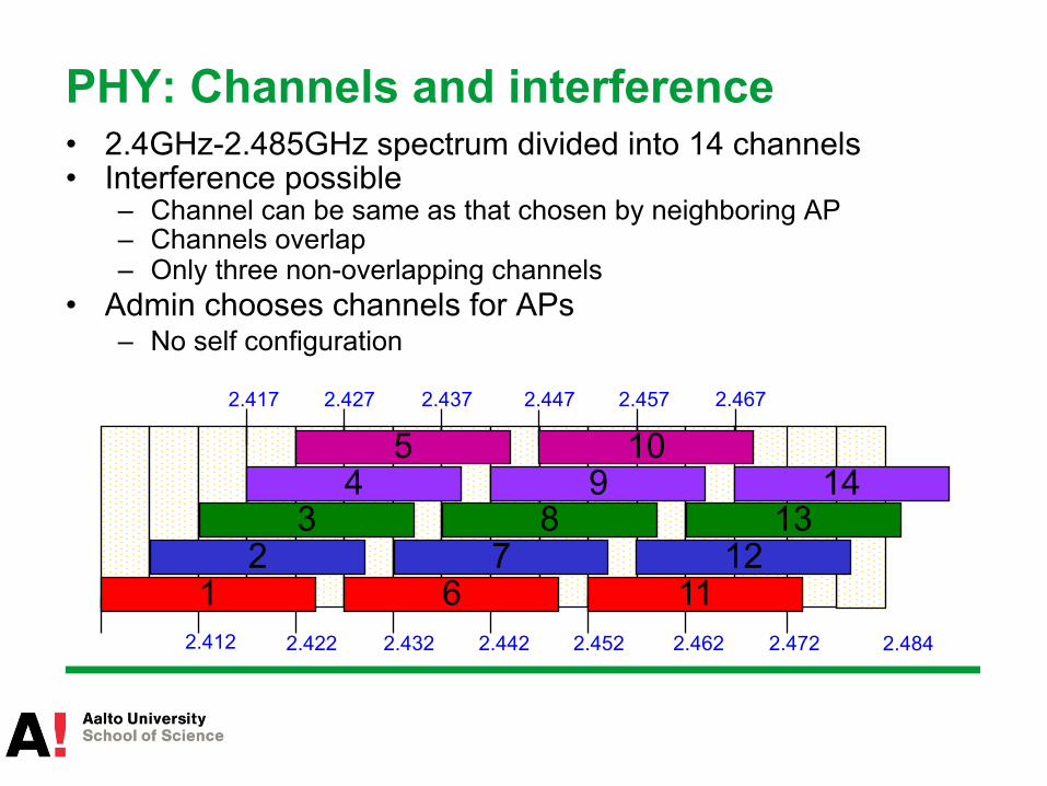
PHY: Channels and interference • 2.4GHz-2.485GHz spectrum divided into 14 channels • Interference possible
– Channel can be same as that chosen by neighboring AP – Channels overlap – Only three non-overlapping channels
• Admin chooses channels for APs – No self configuration
2.412
2.417
2.422 2.432 2.442 2.452 2.462 2.472 2.484
2.427 2.437 2.447 2.457 2.467
2 3
4 5
1 7
8 9
10
6 11 12
13 14
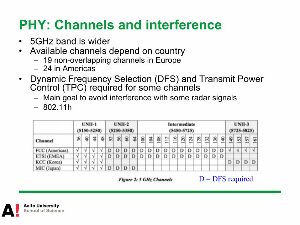
PHY: Channels and interference • 5GHz band is wider • Available channels depend on country
– 19 non-overlapping channels in Europe – 24 in Americas
• Dynamic Frequency Selection (DFS) and Transmit Power Control (TPC) required for some channels – Main goal to avoid interference with some radar signals – 802.11h
D = DFS required
PHY: 2.4 vs. 5 GHz bands
• 802.11n can make a choice between the two – Which is better?
• 2.4GHz band enables a bit longer range • 2.4GHz band more crowded
– Interference from microwave ovens, cordless phones, garage door openers…
– Bluetooth, Zigbee
• 5GHz band is wider – More non-overlapping channels
• 27

PHY: MIMO (802.11n/ac)
• MIMO (multiple input & multiple output) uses multiple antennas and complex signal processing – Separate RF processing chains for each antenna – Each antenna can simultaneously transmit different signal or process received
signal differently • Two main techniques
– Spatial diversity techniques • Send or receive redundant information in parallel along different spatial paths • Increased robustness
– Transmitting multiple independent streams of data • Increased throughput with Space Division Multiplexing (SDM) • One spatial stream per antenna • Up to 600Mbps with four spatial streams
– Fundamental tradeoff between the two • Can be combined to strike a good balance
• 28
PHY: channel bonding (802.11n)
• Also channel bonding possible with 802.11n – 2x20MHz à 1x40MHz channel – Double channel width à double data rate
• 5GHz band offers more channels à more possibilities for bonding
• 29
Outline
• The big picture • (Re)view of basic concepts in wireless communication
– Wireless channels – PHY and MAC layer techniques
• IEEE 802.11 Wireless LAN, a.k.a. Wi-Fi – PHY – MAC – Some enhancements
• Conclusions
802.11 architecture
• Two different modes – Infrastructure mode
• The commonly used one – Ad-hoc mode
• Specific application scenarios • Rarely used in practice
• 31
Ad-hoc mode
• Nodes communicate directly with one another – In mesh networks the topology is quite stable
• Can form MANETs (Mobile Ad Hoc Networks) – Nodes are also mobile – Topology changes constantly
• VANET (Vehicular Ad Hoc Networks) – Moving cars form a mobile network – Specific 802.11 standards developed – Beyond the scope of this course
• 32
Ad-hoc mode
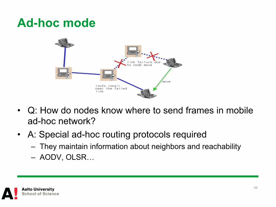
• Q: How do nodes know where to send frames in mobile ad-hoc network?
• A: Special ad-hoc routing protocols required – They maintain information about neighbors and reachability – AODV, OLSR…
• 33
Infrastructure mode
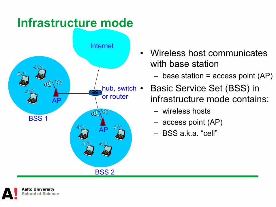
• Wireless host communicates with base station – base station = access point (AP)
• Basic Service Set (BSS) in infrastructure mode contains: – wireless hosts – access point (AP) – BSS a.k.a. “cell”
BSS 1
BSS 2
Internet
hub, switch or router AP
AP

Association
• Host must associate with an AP – Scan channels listening for beacon frames containing AP’s
name (SSID) and MAC address – Select AP to associate with – Optionally perform authentication – Typically run DHCP to get IP address in AP’s subnet

Passive/active scanning
AP 2 AP 1
H1
BBS 2 BBS 1
1 2 2
3 4
Active Scanning: (1) Probe Request frame broadcast from H1 (2) Probes response frame from APs (3) Association Request frame from H1 to
selected AP (4) Association Response frame from AP to
H1
AP 2 AP 1
H1
BBS 2 BBS 1
1 2 3
1
Passive Scanning: (1) Beacon frames from APs (2) Association Request frame from
H1 to selected AP (3) Association Response frame from
AP to H1 Q: Which one is better? A: Passive probing usually takes longer time à prefer active probing (handovers and energy consumption)

Multiple access • 802.11 channel access is CSMA/CA • Avoid collisions: 2+ nodes transmitting at same time
– Received signals become unusable (unable to decode)
• 802.11: CSMA - sense before transmitting – Don’t collide with ongoing transmission by other node
• 802.11: no collision detection! – Difficult to receive (sense collisions) when transmitting due to
weak received signals (fading) • Full duplex radios: only research prototypes exist currently
– Goal is to avoid collisions: CSMA/C(ollision)A(voidance)
CSMA/CA
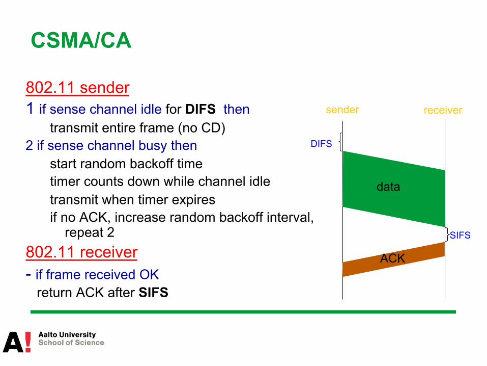
802.11 sender 1 if sense channel idle for DIFS then
transmit entire frame (no CD) 2 if sense channel busy then
start random backoff time timer counts down while channel idle transmit when timer expires if no ACK, increase random backoff interval,
repeat 2 802.11 receiver - if frame received OK return ACK after SIFS
sender receiver
DIFS
data
SIFS
ACK
CSMA/CA (cont.)
• SIFS and DIFS have different lengths (SIFS < DIFS) • Why DIFS/SIFS?
– SIFS allow priority to control frames (e.g. ACKS) or subsequent fragments
• Why random backoff? – Imagine two senders waiting and third one transmitting – Without backoff, both would send right after third one shuts up
• Undetected collision • Entire frames sent in vain
– Random backoff ensures different waiting times • Two waiting à one starts before the other • The second one hears the first one (CA) and backs off
• 39
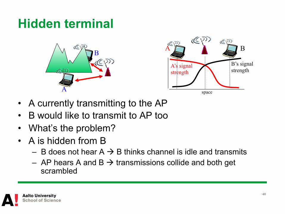
Hidden terminal
• A currently transmitting to the AP • B would like to transmit to AP too • What’s the problem? • A is hidden from B
– B does not hear A à B thinks channel is idle and transmits – AP hears A and B à transmissions collide and both get
scrambled
• 40
A
B A B
A’s signal strength
space
B’s signal strength
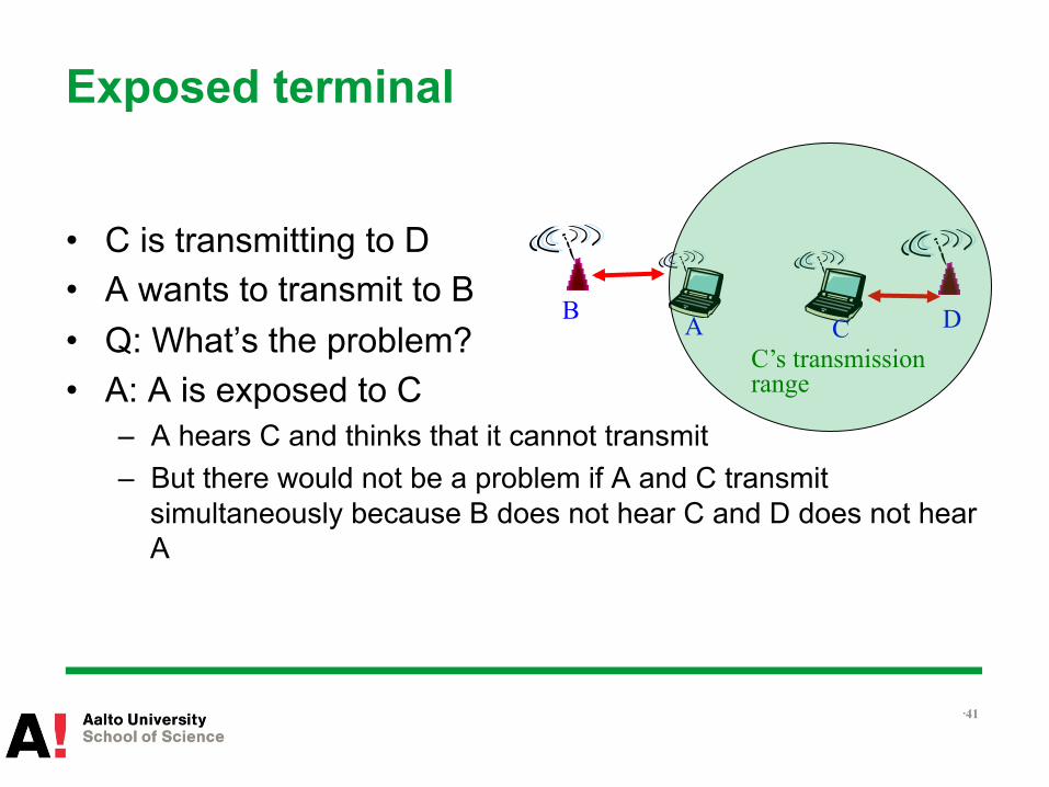
Exposed terminal
• C is transmitting to D • A wants to transmit to B • Q: What’s the problem? • A: A is exposed to C
– A hears C and thinks that it cannot transmit – But there would not be a problem if A and C transmit
simultaneously because B does not hear C and D does not hear A
• 41
A C B D
C’s transmission range
Hidden & exposed terminals
• How would you solve these problems? • Take a moment to discuss this with the person(s) sitting
next to you
• 42
Avoiding collisions with RTS/CTS
• Sender “reserves” channel rather than random access of data frames – Transmits small request-to-send (RTS) packets to BS using
CSMA
• BS broadcasts clear-to-send CTS in response to RTS • CTS heard by all nodes
– sender transmits data frame – other stations defer transmissions
Avoid data frame collisions by using small reservation packets
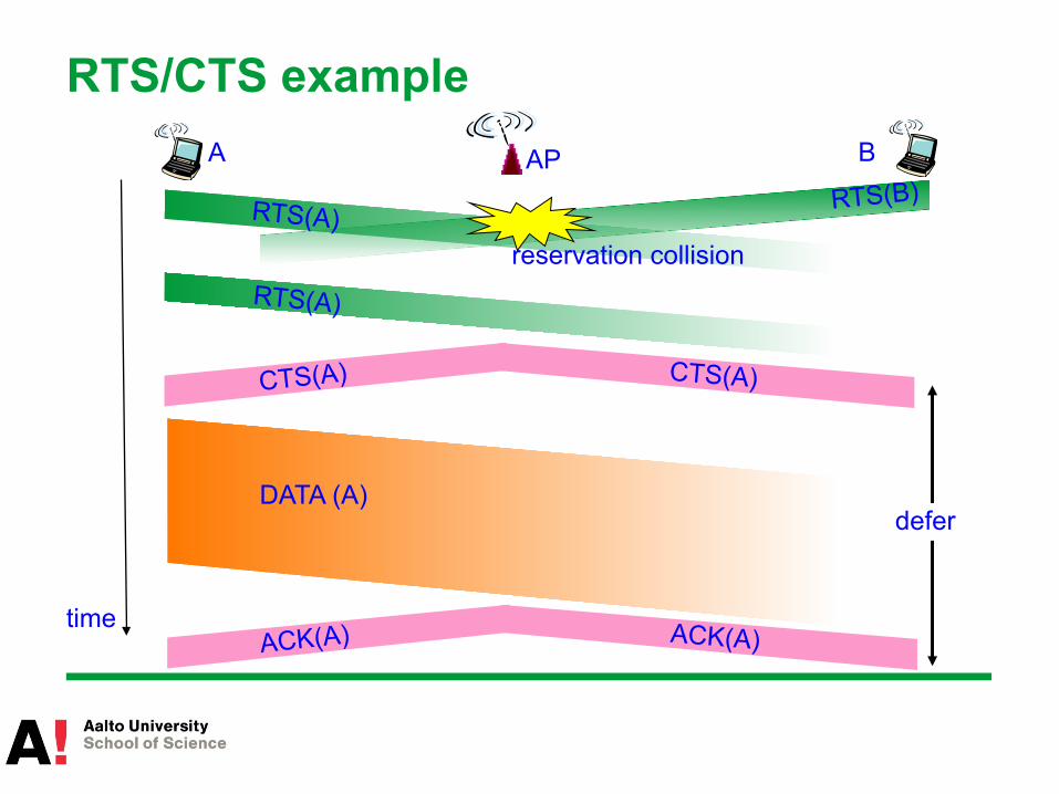
RTS/CTS example AP A B
time
RTS(A) RTS(B)
RTS(A)
CTS(A) CTS(A)
DATA (A)
ACK(A) ACK(A)
reservation collision
defer

RTS/CTS
• Pros – Avoid collisions of long data frames – RTS frames small à their collision is no problem – Helps with hidden terminals because all hear CTS – Helps exposed terminal in some cases
• STA hears RTS but no CTS in response à conclude that it can transmit
• Cons – Adds delay and consumes resources – Useful only with large data frames
• 45
Completely solves the hidden and exposed terminal problems?

Hidden terminal problem still exists
• 46
A
RTS DATA RTS
B C
CTS
Data packet still might suffer collision when node “arrives” after RTS/CTS exchange
D

Hidden terminal problem still exists (cont.)
• 47
A
RTS DATA RTS
C
CTS
Data packet still might suffer collision with unfortunate timing of RTS/CTS packets
D B

Exposed terminal problem still exists
• 48
A
RTS
B
C
CTS
Node C can not receive CTS à nodes would need to be synchronized
DATA
RTS CTS
D

frame control duration address
1 address
2 address
4 address
3 payload CRC
2 2 6 6 6 2 6 0 - 2312 4
seq control
Address 2(transmitter): MAC address of wireless host or AP transmitting this frame
Address 1(receiver): MAC address of wireless host or AP to process this frame
Address 3: MAC address of router interface to which AP is attached
Address 4: used only in ad hoc mode
802.11 frame and addressing

802.11 frame and addressing
Internet router
AP
H1 R1
AP MAC addr H1 MAC addr R1 MAC addr address 1(rcv) address 2 (tx) address 3
802.11 frame
R1 MAC addr H1 MAC addr dest. address source address
802.3 frame
802.11 frame and addressing
• Q: Why are three addresses needed? – Can’t sender just specify router’s MAC address as receiver?
• A: If AP’s address is not the recipient à AP will not processes the frame at all – AP processes only frames addressed to it – AP is not a switch – AP does not necessarily understand IP protocol
• 51

Mobility
hub or switch
AP 2
AP 1
H1 BBS 2
BBS 1
router • Within same subnet – H1 remains in same IP subnet: IP
address can remain same – Hub will just broadcast everything – How does switch know where H1
is? • Self-learning: observe inc. frames and
“remember” behind which switch port H1 is
• If unknown à broadcast • Across subnets
– IP address changes – Need other solutions to maintain
TCP sessions • E.g. HIP

Handoff
• Handoff decision made by client terminal • Handoff can be triggered by
– Low signal strength – Frame loss
• Delay involved in handoff can be significant – Discovery
• Scan for a new AP – Re-authentication
• This part increased with 802.1x (2004)
• 802.11r amendment for fast BSS transition (2008) – Reduces the re-authentication delay – Esp. suitable for VoIP
• 53

Outline
• The big picture • (Re)view of basic concepts in wireless communication
– Wireless channels – PHY and MAC layer techniques
• IEEE 802.11 Wireless LAN, a.k.a. Wi-Fi – PHY – MAC – Some enhancements
• Conclusions
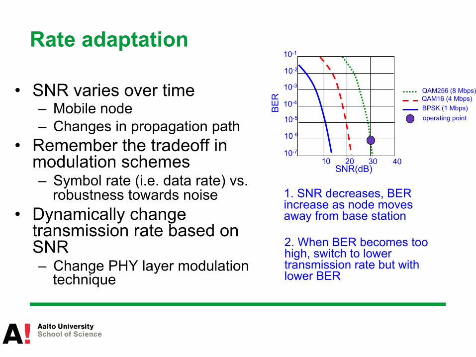
Rate adaptation
• SNR varies over time – Mobile node – Changes in propagation path
• Remember the tradeoff in modulation schemes – Symbol rate (i.e. data rate) vs.
robustness towards noise • Dynamically change
transmission rate based on SNR – Change PHY layer modulation
technique
QAM256 (8 Mbps) QAM16 (4 Mbps) BPSK (1 Mbps)
10 20 30 40
SNR(dB)
BE
R
10-1
10-2
10-3
10-5
10-6
10-7
10-4
operating point
1. SNR decreases, BER increase as node moves away from base station
2. When BER becomes too high, switch to lower transmission rate but with lower BER
Rate adaptation (cont.)
• More tunable “knobs” in 802.11n – Find the best MIMO mode
• Diversity (SS) vs. Spatial Multiplexing (DS) – Find the best rate
• Up to 32 rate options in one MIMO-mode • Ranging from 6Mbps to 600Mbps
– Utilize aggregation • Aggregation feedback • High aggregation rates
• Rate adaptation suggested but not specified in 802.11 standard – Device manufacturers can do it how they want
• 56
Power saving
• PSM = Power Saving Mode • Allows Rx/Tx circuitry to be temporarily shut down • Coordinated with the AP
– Node-to-AP: “I am going to sleep until next beacon frame” – AP knows not to transmit frames to this node, buffers them – Node wakes up before next beacon frame – Beacon frame: contains list of mobiles with AP-to-mobile frames
waiting to be sent – Node will stay awake and request frames buffered at AP if any;
otherwise sleep again until next beacon frame • Sleep mode consumes ten times less power than idle
mode
• 57
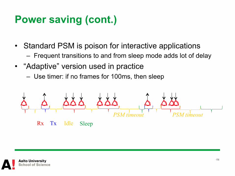
Power saving (cont.)
• Standard PSM is poison for interactive applications – Frequent transitions to and from sleep mode adds lot of delay
• “Adaptive” version used in practice – Use timer: if no frames for 100ms, then sleep
• 58
PSM timeout PSM timeout Rx Tx Idle Sleep
Quality of Service
• Different traffic has different requirements/tolerance – Throughput, delay, jitter, packet loss
• Enhanced Distributed Channel Access (EDCA) – A.k.a. EDCF (Enhanced Distributed Coordination Function) – In 802.11e amendment – Wi-Fi certification: Wireless Multimedia Extensions (WME) a.k.a.
Wi-Fi Multimedia (WMM) • Subset of 802.11e mechanisms
• 59
EDCA
• Divides traffic into four different priority levels, i.e. Access Categories (AC) – Best effort – Background – Video – Voice
• Basically set channel sensing time (contention) and transmit time depending on priority level
• 60

EDCA (cont.) • Uses four parameters:
– Minimum contention window size (CWmin) – Maximum contention window size (CWmax) – Arbitration Interframe Space (AIFS) = variable DIFS – Transmission Opportunity (TXOP): total time that STA can
transmit after winning ch access (not necessarily a single frame)
• 61
AC Application CWmin CWmax AIFS TXOP limit (802.11g)
0 Best effort CWmin CWmax 2 0 1 Background CWmin CWmax 1 1.5ms 2 Video (CWmin+1)/2 - 1 CWmin 1 3ms 3 Voice (CWmin+1)/4 - 1 (CWmin+1)/2 - 1 1 1.5ms

Rate Anomaly and TXOP
• Rate anomaly is well-known in WiFi 802.11 networks – Low-rate stations degrade throughput of
high-rate stations • Why does rate anomaly exist?
– Stations reduce data rates when signal strength is poor
– Low-rate stations’ packets consume more airtime
– Per-packet fairness in basic 802.11 à Higher-rate stations receive less airtime à throughput degrades
• TXOP alleviates this fairness issue by providing time slots
54Mbps
AP
A
54Mbps
B
Thro
ughp
ut (M
bps)
10
20
30
0
A, B near AP A far from AP
B
A
B A
18Mbps

Frame aggregation
• 802.11n uses frame aggregation • Pack several frames in one aggregate frame • Need also to use Block acknowledgments
– Acknowledge several frames in one ACK
• Reduces overhead due to – headers, inter-frame spacing, and acking
• 63
Wi-Fi Direct
• A way to do device-to-device (D2D) communication with Wi-Fi – No infrastructure needed
• One of the two devices acts as an AP – The devices negotiate this upon first contact
• Not the same as 802.11 ad-hoc mode – In ad-hoc mode, there is no AP and specific routing protocols
are used (multihop)
• 64

Security
• Confidentiality, authentication, access control • Many different security mechanisms have been
proposed – New proposal after previous one has been hacked
• Currently used ones include – WPA, WPA2 – Authentication using 802.1x with EAP
• WLAN security lecture at T-110.5241 Network Security
• 65
Future of Wi-Fi: Gigabit and beyond
• 802.11ac with higher data rates – Wider channels – More antennas (MIMO)
• WiGig (Wireless Gigabit Alliance) – Originally 802.11ad – Uses 60GHz band
• Can use much wider channel – Short distance, point to point links
• Beamforming • Requires line of sight in practice
– Different target scenarios than 802.11ac – Theoretical max. throughput of 7Gb/s with single antenna
• 66
Summary
• IEEE 802.11 Wireless LAN, a.k.a. Wi-Fi is the main Wireless LAN out there
• Standard by IEEE, lots of amendments over the years • Infrastructure mode: access to Internet via access point
– Also ad-hoc available
• Multi-gigabit data rates already possible with 802.11ac – PHY: MIMO, OFDM, channel bonding – MAC: frame aggregation
• Enhancements exist for – Security, QoS, power saving, fast handoff…
• 67


