1. Deep - groove ball bearing and rotary shaft seal on Tracker™ shaft 1.1 Leakage on Compensating Hole In case of leakage on the compensating hole or in the Tracker™ housing, check the rotary shaft lip seal. In most cases of this form of leakage, the deep-groove ball bearing in the Tracker™ housing and the partial deep-groove ball bearing in the gear wheel could be damaged. Check for leakage monthly.
1.2 Radial Tolerance on Tracker™ shaft In case of excessive radial clearance on the Tracker™ shaft (this can be checked on the Tracker™ wheel by removing the cover) the cause is always a defective deep-groove ball bearing in the Tracker™ housing. Examination twice a year.
2. Tracker™ Bearing & Rotary Shaft Lip Seal Repair To repair the bearing & rotary shaft lip seal on your Tracker™, follow these instructions. Remove cover (BTV784337), gear box cover (BTV784342) and plastic wheel (ZK3794434, BTV784442, BTD684443 and ZK3794435) completely. Screw off turbine covers (BTV7 84419 + ZK18 94376)
Attach Tracker™ wheel (BTV784312) with the left hand and remove screw (BTC484330) M10 to get to the Tracker™ shaft.
Tap out the clamping sleeve (ZD1593196) with 4mm punch (standard tool).
Pull out Tracker™ wheel (BTV784312) with shaft (BTC484330). Pull out sliding bush (ZK1494152).
Remove gear and spacer ring from gear case. Tap out shaft seal packing (ZK0994377) with guide bush for shaft (BTC584388).
In case deep-groove ball bearing (ZK1994372) is intact: Tap out with pressure bolt No.1 (BTC584431) to gear case.
If deep-groove ball bearing (ZK1994372) is defective (individual parts):
Apply internal extractor Ø19-24 and tap through with pressure bolt No.1 (BTC584431) towards gear case. Check Tracker™ housing; if needed it replaced with: 1 x Tracker™ housing BBH284418 4 x O-ring ZK1816551 4 x countersunk screw ZD0493195
Set up housing on edge.
Push in new deep-groove ball bearing (ZK1994372) with pressure bolt no. 2 (BTC584432)
Only push on outer ring of deep-groove ball bearing!
Insert new guide bushing for Tracker™ shaft (BTC584388) with pressure bolt no. 1 (BTC584431)
Insert new shaft seal (ZK0994377) with pressure bolt no. 3 (BTC584433) – opening has to be visible from the outside.
Lubricate rotary shaft lip seal with acid free grease (Molikode).
Check the assembled ball bearings for zero clearance and free movement in the gears & cover Tracker™ shaft. If necessary replace with a new deep-groove ball bearing (ZK1994372).
Insert and ensure properly position the Tracker™ shaft and wheel with sliding bush (ZK1494152)
Bead the following pieces on Tracker™ shaft: Spacer bushing 1 (BTC584317) Gear 2 (BTV784347) Spacer bushing 2 (BTC584318) Gear 2 (BTV784347) Spacer bushing 2 (BTC584318) Gear 1 (BTV784346) Spacer (BTC584372)
Tightly screw on cover for Tracker™ shaft (BTC684371) with deep-groove ball bearing (ZK1994372) (3x ZD0293188)
Turn Tracker™ shaft and gear 1 so the bore holes are aligned. Tap clamping sleeve (ZD1593196) with 4mm punch, deeper than the dedendum.
Apply blue Loctite Tracker™ shaft thread.
Unscrew nut clamp for Tracker™ shaft (BTA484370), attaching Tracker™ wheel with the left hand and tighten net with 9-10mm.
If not enough torque is applied, leakage on the Tracker™ shaft can occur causing damage to the deep-groove ball bearing.
Re-assemble wheels, gear cover and cover to the unit.
Annotation For this repair order the following pieces: - 6 x deep-groove ball bearing ZK1994372 - 1 x shaft seal ZK0994377 - 1 x guide bush for Tracker™ shaft BTC584388 - 1 x clamping sleeve spare part ZD1593196 - 1 x clamping nut for Tracker™ shaft BTA484370 The following special tools are needed: - pressure bolt 1 BTC584431 - pressure bolt 2 BTC584432 - pressure bolt 3 BTC584433 - bull bearing remover ZB1198227
B. Examination of cable and cable drum 1. Examination of Cable The cable should be inspected once a month for any visible damage. If the cable is frayed, the cable drum should be replaced. Cables damages can occur when the cable is coiled beside the drum. Frequently the reason is not enough tension in the cable before operation. 2. Replacement of Cable Drum Remove nuts from shearing screw BTC484336 and tap through shearing screw through the shaft. Pull down driver BBK384341 from the shaft.
Cut cable so that the limit stop for Tracker™ (BTC584416 and ZK1484424) can be removed from the cable.
Remove cable drum from the shaft and replace with a new cable drum BB0284412.
Attach spring, brass washer and Teflon washer (drum brake) before putting on the cable drum! Feed cable into cable guide, shut-off rod and limit stop. Form a loop at the end and apply knot.
Make sure the loop goes over the spur! Attach driving arm using a new shearing screw BTC484336. Adjust limit stop. Your Tracker™ is ready to operate. Parts needed: 1 x cable drum with cable BBO284429 1 x shearing screw BTC484336 1 x 110m of cable ZK2494226
C. Checking the valve 1. Check shut-off valve for leaks and debris. After every watering job, check to see if the valve is watertight. Especially when using reclaimed water, the valve may fail to close or open completely due to small stones or grass stuck in the valve. This will result in the sprinkler losing pressure.
2. Cleaning and replacing the valve Remove valve casing with an SW5 Allen key.
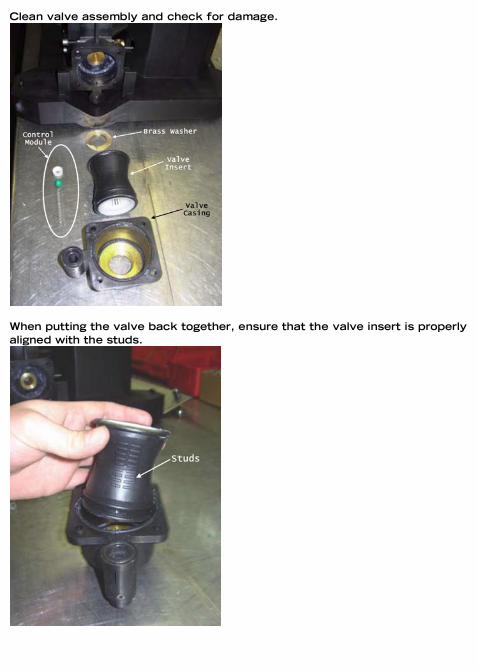
Clean valve assembly and check for damage.
When putting the valve back together, ensure that the valve insert is properly aligned with the studs.
Re-assemble control module (1st spring, 2nd ball bearing, 3rd seal), as per detail X on the individual parts list. Insert brass washer with chamfer facing the valve insert. Apply non-acidic grease (Molykote) to valve insert and put re-assemble.
Replace valve casing using SW5 Allen key.
Spare parts: 1 x O-ring, diameter 67x2.5 BBO284429 1 x O-ring, diameter 18x2.5 BTC484336 1 x Valve casing BBH284420 1 x Valve insert BBK584410 1 x Valve pressure spring ZK1491560 1 x Ball bearing ZK0894281 1 x Sealant ring ZK1494487