55

T a b l e o f C o n t e n t s
4WD Output Disassembly and Assembly .................................................................. 24 Brakes Removal and Installation ................................................................................ 43 Center Valve Block Disassembly and Assembly ...................................................... 33 Charge Pump Disassembly and Assembly ................................................................. 2 Charge Pump Removal and Installation ...................................................................... 2 Control Arm and Damper Removal and Installation ................................................... 1 Differential (2WD) Disassembly and Assembly ........................................................ 20 Differential (4WD) Disassembly and Assembly ........................................................ 21 Differential Lock Shaft Disassembly and Assembly ................................................. 19 General Specifications ................................................................................................... iv Hydrostatic Flow Diagram Check Points ................................................................... 44 Hydrostatic Pump Inspection ....................................................................................... 35 Hydrostatic Transmission 2WD and 4WD ................................................................. 28 Hydrostatic Transmission Installation ......................................................................... 35 Hydrostatic Transmission Motor Disassembly and Assembly (2WD) ................... 29 Hydrostatic Transmission Motor Disassembly and Assembly (4WD) ................... 31 Hydrostatic Transmission Motor Installation ............................................................. 34 Inspection of Transaxle Case ...................................................................................... 39 K92 Transmission Component Location ..................................................................... vi Ordering Replacement Parts Online ............................................................................. ii PTO Brake Removal and Installation ........................................................................... 6 PTO Clutch Disassembly, Inspection and Assembly ............................................... 22 PTO Drive Train (Mid-PTO) Removal and Installation .............................................. 9 PTO Drive Train (Mid and Rear PTO) Removal and Installation ........................... 11 PTO Relief Valve Disassembly, Inspection and Assembly ....................................... 6 PTO Relief Valve Removal and Installation ................................................................ 6 PTO Solenoid Valve ........................................................................................................ 4 Rear Axle Assembly - Disassembly and Assembly .................................................. 42 Rear Axle Assembly Removal and Installation ......................................................... 41 Rear PTO Assembly ..................................................................................................... 17 Rear PTO Removal and Installation ........................................................................... 14 Recommended Tools and Equipment ......................................................................... iv Serial Number Location ................................................................................................. iv Transaxle (Right Cover) Disassembly and Assembly .............................................. 38 Transaxle Disassembly ................................................................................................ 36 Troubleshooting Guides ............................................................................................... 46
i

Ordering Replacement Parts Online
w w w . t u f f t o r q . c o m
Home
Page 1
Page 2
Page 3
At Tuff Torq, we offer our customers quality
products at a modest price. A manufacturer
of hydrostatic and gear drive transmissions
for the power equipment industry, Tuff Torq
offers a complete line of transmissions and
parts to help fit your needs. Designed to meet the needs of our OEM custom-ers,
this web site is designed to assist service and re-pair
facilities in locating and ordering parts for Tuff Torq
manufactured transmissions. It also provides
transaxle parts identification, troubleshooting
guides, online ordering capabilities, as well as
providing you with a complete inventory of parts,
service and same day shipping. If you are a registered user, please login (from the
Welcome Page) to access the parts ordering system. If you are not a OEM customer or authorized
service distributor, you may need to contact your
equipment manufacturer or authorized dealer.
Select your brand (from the Welcome page) and
you will be directed to the appropriate web site.
Navigating the web site:
To access Tuff Torq’s web site, type in www.
tufftorq.com from your Internet browser. From
the Home page, click on “Service” to enter the
Online Ordering page (Ref. Page 1)
From The Online Ordering page, click on “Click
here to enter service web site” to enter the
Welcome page (Ref. Page 2).
From the Welcome page, login (for register
users) and follow the on screen instructions. Or,
click on “Catalog/Order” to enter Store Browser
(Ref. Page 3).
From the Catalog/Order page, select your
transaxle model, e.g., K61. Click on “K61” to find
the serial number for your model (Ref. Page 4). From the Model Series page, click on, your Model to
enter the Serial Number Range page (Ref. Page 5).
ii

Page 4
Page 5
Page 6
Page 7
Tuff Torq K92 Hydrostatic Transaxle
Having your Model, and Model Series, click on
the serial number to enter the Online Ordering
page for you Transaxle (Ref. 6).
Navigate through the exploded parts illustration until
the desired part has been identified. Take note of the
part’s figure number. Locate the part number in the
parts listing. You can add the part to your shopping cart
and return to the exploded illustration or—click on the
item to go to the Product Explorer page for additional
detail about the part (Ref. Page 7).
Thank you for visiting and ordering online with
Tuff Torq.
iii
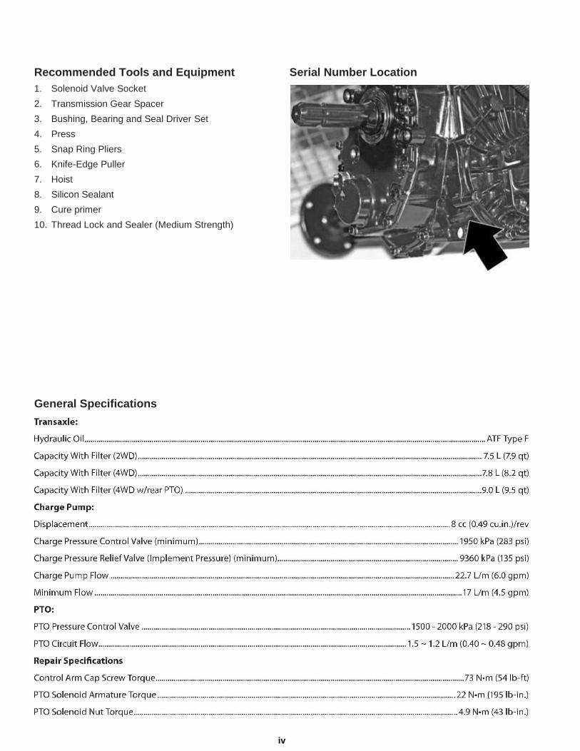
Recommended Tools and Equipment Serial Number Location 1. Solenoid Valve Socket 2. Transmission Gear Spacer 3. Bushing, Bearing and Seal Driver Set 4. Press 5. Snap Ring Pliers 6. Knife-Edge Puller 7. Hoist 8. Silicon Sealant 9. Cure primer 10. Thread Lock and Sealer (Medium Strength)
General Specifications
iv

Tuff Torq K92 Hydrostatic Transaxle
v

K92 Transmission Component Location
Forward/Reverse Main Transmission Case
Control Valves
Charge Pump
4WD Assembly (Optional)
Center Block Valve
Motor Case Assembly
Brake Arm/ Brake Assembly
Differential Lock Arm
Axle Assembly
K92 Hydrostatic Transaxle
Oil Port (Fill Tube not Shown)
PTO Brake Cover
PTO Pressure Test Port
Control Arm Damper
PTO Electrical Engagement Solenoid
PTO Pressure Control Valve
Rear PTO Shaft
(Optional)
Differential Lock Shaft
vi

Tuff Torq K92 Hydrostatic Transaxle
Control Arm and Damper Removal and Installation
Before beginning tear down clean work area thoroughly
and cover workbench with clean paper. This is extremely
impor-tant as just one grain of sand can cause damage to
the Hy-drostatic Rotating Group in the Transaxle.
Fig. 1, Control Arm and Damper Disassembly A - Control Arm B - Washer C - Main Cap Screw D - Spring Locking Pin E - Washer F - Damper G - Pivot Stud H - Clevis Pin I - Spring Locking Pin
1. Remove spring locking pins (D) and washers (E) from both sides of damper (F). (Fig. 1)
2. Slide damper off of pivot stud (G) and clevis pin (H).
Inspect and, if defective, replace damper as an assembly. 3. To remove control arm (A), remove spring locking pin (I)
and disconnect foot control rod (D) from control arm.
4. Remove cap screw (C) and washer (B) from
control arm. (Fig. 1) 5. Remove control arm (A). (Fig. 1) 6. Install control arm the same as removal, and install
washer and cap screw. Tighten cap screw (C) to
73 N•m (54 lb-ft).
NOTE: If removed, use medium strength thread
lock and sealer on pivot stud (G) threads. 7. Install damper with open end of clamp facing down. 8. Install remaining washers and spring locking pins.
CAUTION: ALWAYS WEAR SAFETY GLASSES WHILE PER- FORMING ANY MAINTENANCE ON TRANSAXLE!
NOTE: Access to cap screw (C) is through hole in right frame.
1
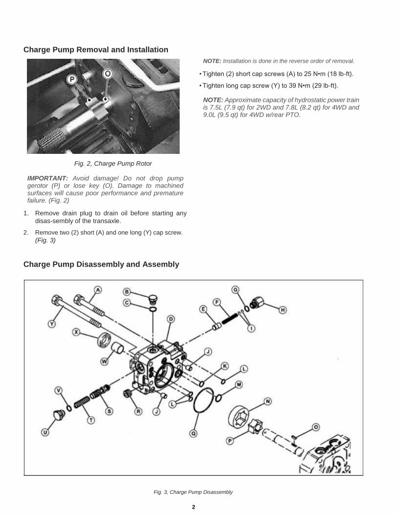
Charge Pump Removal and Installation
Fig. 2, Charge Pump Rotor
IMPORTANT: Avoid damage! Do not drop pump gerotor (P) or lose key (O). Damage to machined surfaces will cause poor performance and premature failure. (Fig. 2)
1. Remove drain plug to drain oil before starting any
disas-sembly of the transaxle. 2. Remove two (2) short (A) and one long (Y) cap screw.
(Fig. 3)
Charge Pump Disassembly and Assembly
NOTE: Installation is done in the reverse order of removal. • Tighten (2) short cap screws (A) to 25 N•m (18 lb-ft). • Tighten long cap screw (Y) to 39 N•m (29 lb-ft).
NOTE: Approximate capacity of hydrostatic power train is 7.5L (7.9 qt) for 2WD and 7.8L (8.2 qt) for 4WD and 9.0L (9.5 qt) for 4WD w/rear PTO.
Fig. 3, Charge Pump Disassembly
2

Tuff Torq K92 Hydrostatic Transaxle
Charge Pump Disassembly and Assembly (continued) A - Cap Screw (2 used), M10 x 65 B - Plug C - O-ring D - Pump Body E - Pressure Valve F - Spring G - O-ring H - Plug I - Shims J - Pin K - O-ring L - O-ring M - O-ring N - Outer Rotor O - Key P - Inner Rotor Q - O-ring R - Plug S - Reducing Valve T - Spring U - Reducing Plug V - O-ring W - Bushing X - Seal Y - Cap Screw, M10 x 105
6. Check small orifice in reducing valve (S) spool
for obstruction. 7. Replace parts if necessary. 8. Remove plug (H) to remove charge pressure relief
valve parts (E, F, G, and I). (Fig. 3) 9. Inspect parts for scoring, wear or damage. 10. Replace parts if necessary. 11. Inspect seal (X) and bushing (W) for wear or damage. 12. If bushing is removed, apply clean hydraulic oil to
bushing and use a disk driver to install bushing to
bot-tom of bore. 13. If seal is replaced, apply clean hydraulic oil to new
seal. Install seal with open side into pump body.
Push seal to bottom of bore. 14. Apply clean hydraulic oil to all machined surfaces
before assembly.
NOTE: Installation is done in the reverse order of removal.
NOTE: Charge pressure control valve and pressure reducing valve can be removed when the charge pump is in the machine. To inspect valve seats and bores, the pump must be removed.
1. Disassemble all parts of charge pump (D). (Fig. 3) 2. Inspect O-rings (C, K, L, M, and Q) for cuts or
damage. Replace as necessary. (Fig. 3)
NOTE: Pump gerotor (N and P), seal (X), body (D), and
pressure reducing valve (S) parts must be replaced as a set. 3. Inspect gerotor charge pump parts (N - P). Replace
parts if worn, chipped, scored or damaged. 4. Remove plug (U) to remove pressure reducing
valve parts (V, S, and T). (Fig. 3) 5. Inspect parts for scoring, wear or damage.
3

Directional Control Valves Removal and Installation:
Fig. 4, Control Valves
1. Remove directional control valves (A). (Fig. 4)
NOTE: Installation is done in the reverse order of removal. • Tighten directional control valves to 35 N•m (26 lb-ft). Disassembly, Inspection and Assembly:
Fig. 5, Control Valve Disassembly
A - Reverse Control Valve (with orifice) B - Orifice C - Forward Control Valve D - O-ring E - Backup Ring F - O-ring
1. Disassemble parts from directional control valves. 2. Inspect O-rings and backup rings for damage.
3. Plunger pin must move freely. 4. Internal valve must move freely when valve is shaken. 5. Make sure orifice and all passages are free of
any obstruction. 6. Assemble parts.
IMPORTANT: Avoid damage! The reverse control valve must be installed in the left port. The control valve can be identified by a small orifice drilled into a land between the two sets of valve passageways.
Fig. 6, Control Valve Location
PTO Solenoid Valve Removal and Installation:
IMPORTANT: Avoid damage! Do not bend, twist or damage solenoid armature. Do not damage machined sur-faces or sharp edges of spool or sleeve. PTO will not function or will function erratically if spool, sleeve or armature is dam-aged.
Fig. 7, Charge Pump Rotor
4
Tuff Torq K92 Hydrostatic Transaxle
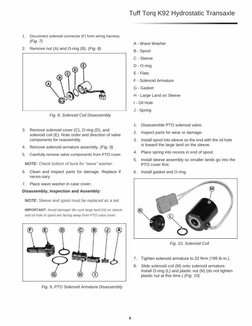
1. Disconnect solenoid connector (F) from wiring harness.
(Fig. 7) 2. Remove nut (A) and O-ring (B). (Fig. 8)
Fig. 8, Solenoid Coil Disassembly
3. Remove solenoid cover (C), O-ring (D), and
solenoid coil (E). Note order and direction of valve
components for reassembly. 4. Remove solenoid armature assembly. (Fig. 9) 5. Carefully remove valve components from PTO cover.
NOTE: Check bottom of bore for “wave” washer. 6. Clean and inspect parts for damage. Replace if
neces-sary. 7. Place wave washer in case cover. Disassembly, Inspection and Assembly:
NOTE: Sleeve and spool must be replaced as a set.
IMPORTANT: Avoid damage! Be sure large land (H) on sleeve
and oil hole in spool are facing away from PTO case cover.
Fig. 9, PTO Solenoid Armature Disassembly
A - Wave Washer B - Spool C - Sleeve D - O-ring E - Flats F - Solenoid Armature G - Gasket H - Large Land on Sleeve I - Oil Hole J - Spring
1. Disassemble PTO solenoid valve. 2. Inspect parts for wear or damage. 3. Install spool into sleeve so the end with the oil hole
is toward the large land on the sleeve. 4. Place spring into recess in end of spool. 5. Install sleeve assembly so smaller lands go into the
PTO cover first. 6. Install gasket and O-ring.
Fig. 10, Solenoid Coil
7. Tighten solenoid armature to 22 N•m (195 lb-in.). 8. Slide solenoid coil (M) onto solenoid armature.
Install O-ring (L) and plastic nut (N) (do not tighten
plastic nut at this time.) (Fig. 10)
5
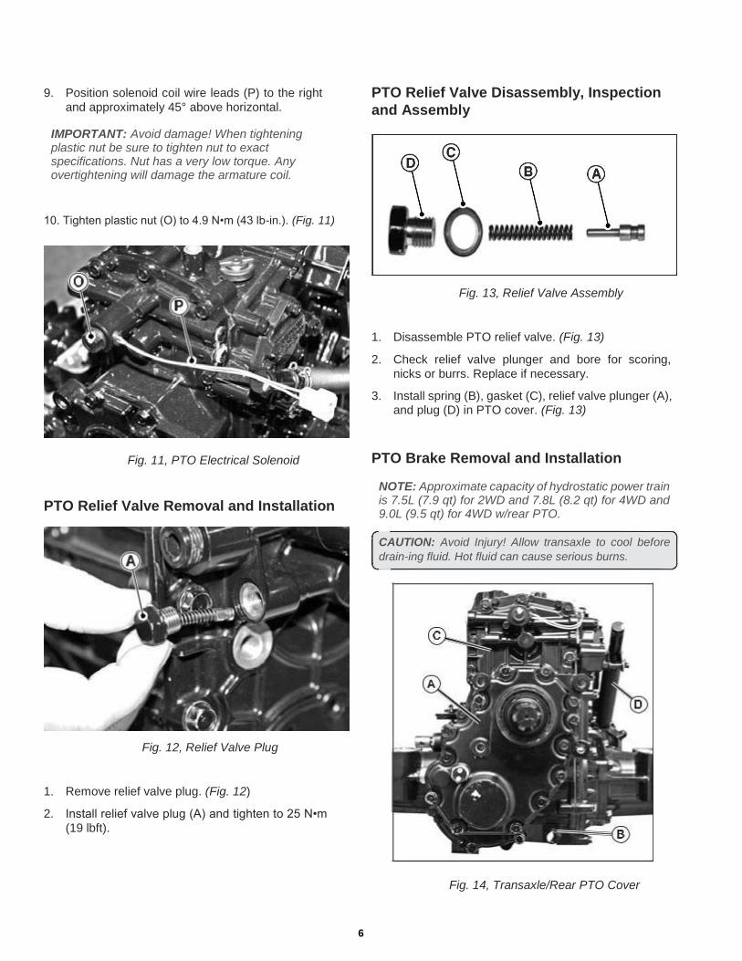
9. Position solenoid coil wire leads (P) to the right
and approximately 45° above horizontal.
IMPORTANT: Avoid damage! When tightening plastic nut be sure to tighten nut to exact specifications. Nut has a very low torque. Any overtightening will damage the armature coil.
10. Tighten plastic nut (O) to 4.9 N•m (43 lb-in.). (Fig. 11)
Fig. 11, PTO Electrical Solenoid
PTO Relief Valve Removal and Installation
Fig. 12, Relief Valve Plug
1. Remove relief valve plug. (Fig. 12) 2. Install relief valve plug (A) and tighten to 25 N•m
(19 lbft).
PTO Relief Valve Disassembly, Inspection and Assembly
Fig. 13, Relief Valve Assembly
1. Disassemble PTO relief valve. (Fig. 13) 2. Check relief valve plunger and bore for scoring,
nicks or burrs. Replace if necessary. 3. Install spring (B), gasket (C), relief valve plunger (A),
and plug (D) in PTO cover. (Fig. 13)
PTO Brake Removal and Installation
NOTE: Approximate capacity of hydrostatic power train is 7.5L (7.9 qt) for 2WD and 7.8L (8.2 qt) for 4WD and 9.0L (9.5 qt) for 4WD w/rear PTO.
CAUTION: Avoid Injury! Allow transaxle to cool before
drain-ing fluid. Hot fluid can cause serious burns.
Fig. 14, Transaxle/Rear PTO Cover
6

Tuff Torq K92 Hydrostatic Transaxle
1. Remove plug (B) to drain oil from transaxle. (Fig. 14)
NOTE: If rear PTO is installed, remove necessary rear
PTO components before rear transaxle cover removal.
(See “Rear PTO Removal and Installation” on page 12.) 2. Remove optional rear PTO (A), if installed. (See “Rear
PTO Removal and Installation” on page 12.) (Fig. 14) 3. Remove rear transaxle cover (C). (Fig. 14) 4. Remove control arm damper (D), (Fig. 14-15), to gain
access to (3) cap screws (K), (Fig. 15), holding PTO brake
cover (J), (Fig. 15), to transaxle side cover. (See “Control
Arm and Damper Removal and Installation” on page 1.)
Fig. 15, PTO Brake Cover Removal
Fig. 16, PTO Brake Cover Kit
NOTE: Installation is done in the reverse order of diassembly.
7
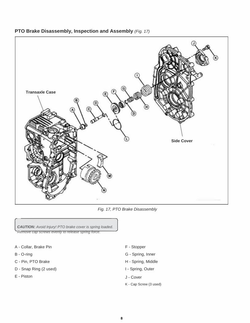
PTO Brake Disassembly, Inspection and Assembly (Fig. 17)
Transaxle Case
Side Cover
Fig. 17, PTO Brake Disassembly
CAUTION: Avoid Injury! PTO brake cover is spring loaded.
Remove cap screws evenly to release spring force.
A - Collar, Brake Pin B - O-ring C - Pin, PTO Brake D - Snap Ring (2 used) E - Piston
F - Stopper G - Spring, Inner H - Spring, Middle I - Spring, Outer J - Cover K - Cap Screw (3 used)
8

Tuff Torq K92 Hydrostatic Transaxle
L - O-ring M - PTO Brake Shoe N - PTO Clutch Assembly 1. Carefully pull piston assembly from case using a
pliers. Do not damage pin. (Fig. 17) 2. Remove PTO clutch assembly (N) and brake
shoe (M) together.
NOTE: PTO brake pin, piston, springs, and O-rings, etc., (parts C thru I), must be replaced as a set.
3. Check pin and piston for burrs, scoring or wear. 4. Replace brake shoe if grooves in shoe contact
surface are not visible. 5. Inspect O-rings for cuts or damage. 6. Inspect springs for cracks or damage. 7. Apply petroleum jelly to O-rings and seal on end of
PTO clutch shaft. 8. Install piston assembly and clutch assembly. 9. Clean mating surface of side cover and transaxle
case. Be sure threaded holes are clean. 10. Apply a bead of silicon sealant to cover mating of
sur-face.
IMPORTANT: Avoid damage! Be sure side cover is aligned with transaxle case and installed within 3 mm (1/8 in.) of case before tightening cap screws. Major damage can occur to cover and/or case if cover is not installed properly before tightening cap screws.
Transaxle Cover Cap Screw Torque Specifications:
• Used Transaxle Case . . . . . . . . . . . . . . 25 N•m (18 lb-ft)
• New Transaxle Case . . . . . . . . . . . . . . . 30 N•m (22 lb-ft)
NOTE: Remove necessary rear PTO components before rear transaxle cover removal. (See “Rear PTO Removal and Instal-lation” on page 14.)
2. Remove optional rear PTO (A), if installed. (See “Rear
PTO Removal and Installation” on page 14.) (Fig. 18) 3. Remove rear transaxle cover (C). (Fig. 18)
Fig. 18, Transaxle Cover
4. Remove PTO clutch assembly (A). (Fig. 19) 5. Remove PTO idler gear assembly (N). (Fig. 19) 6. Remove PTO gear (K). (Fig. 19) 7. Left axle must be removed to remove PTO output
shaft assembly (L), (See “Rear Axle Assembly
Removal and Installation” on page 41.)
PTO Drive Train (Mid-PTO) Removal and Installation
NOTE: Approximate capacity of hydrostatic power train is 7.5L (7.9 qt) for 2WD and 7.8L (8.2 qt) for 4WD and 9.0L (9.5 qt) for 4WD w/rear PTO.
Removing:
CAUTION: Avoid Injury! Allow transaxle to cool before
drain-ing fluid. Hot fluid can cause serious burns.
1. Remove plug (B) to drain oil from transaxle. (Fig. 18) 9

PTO Drive Train (Mid-PTO) Removal and Installation (continued) 8. Inspect ball bearings and needle bearing for
smooth rotation.
NOTE: Idler gear (N) and shaft (O) must be replaced
as a set. (Fig. 19) 9. Inspect gears and splines for missing or chipped teeth,
wear or damage. Replace parts if necessary.
A - PTO Clutch Assembly B - Snap Ring C - Needle Bearing D - Washer E - Seal F - Needle Bearing G - Washer H - Cap Screw I - Ball Bearing J - Snap Ring K - Mid-Mount PTO Gear L - PTO Output Shaft M - Snap Ring N - PTO Idler Gear O - PTO Idler Shaft P - Washer
Fig. 19, Rear PTO Cover Removed
Fig. 20, PTO Drive Train (Mid-PTO) Disassembly
10

Tuff Torq K92 Hydrostatic Transaxle
Installing: 1. If replaced, install new needle bearing (F) from inside
case with bearing identification marks toward the inside of
the case. Push bearing tight against shoulder in bore.
(Fig. 20)
2. Install new seal (E) with the open, spring side towards the inside of the case. (Fig. 20)
3. Push seal against shoulder in bore. 4. Install mid-mount PTO gear (K) so side with the
longer center hub is towards bearing. (Fig. 20) 5. Clean mating surfaces of rear cover and case. Be
sure threaded holes are clean and two O-rings are
in position in rear cover. 6. Apply petroleum jelly to seal on shaft of PTO clutch
as-sembly. 7. Apply a bead of silicon sealant to cover mating surface.
IMPORTANT: Avoid damage! Be sure rear cover is aligned with transaxle case and installed within 4 mm (1/8 in.) of case before tightening cap screws. Major damage can occur to cover and/or case if cover is not installed properly before tightening cap screws.
8. Install transaxle drain plug. Refill transaxle with ap-
proximately 9.0L (9.5 qt) using ATF Type F as
required) to crosshatched area of dipstick. Rear Cover Cap Screw Torque Specifications:
• Used Transaxle Case . . . . . . . . . . . . . . . 25 N•m (18 lb-ft)
• New Transaxle Case. . . . . . . . . . . . . . . . 30 N•m (22 lb-ft)
• Internal Cap Screws. . . . . . . . . . . . . . . . 27 N•m (20 lb-ft)
PTO Drive Train (Mid and Rear PTO) Remov-al and Installation
NOTE: Approximate capacity of hydrostatic power train is 7.5L (7.9 qt) for 2WD and 7.8L (8.2 qt) for 4WD and 9.0L (9.5 qt) for 4WD w/rear PTO.
Removing:
CAUTION: Avoid Injury! Allow transaxle to cool before
drain-ing fluid. Hot fluid can cause serious burns. 1. Remove plug to drain oil from transaxle (AA). (Fig. 21)
Fig. 21, PTO Drive Train (Mid and Rear PTO) Removal
NOTE: Remove necessary rear PTO components before rear transaxle cover removal. (See “Rear PTO Removal and Instal-lation” on page 14.)
2. Remove rear PTO (AD). (See “Rear PTO
Removal and Installation” on page 14.) 3. Remove (9) cap screws (AC) to remove rear cover (AB).
(Fig. 21) 4. Remove PTO clutch assembly (A). (Fig. 22)
IMPORTANT: Avoid damage! When removing snap ring
(B), be sure not to lose needle bearing (C) or washers (D). 5. Remove PTO idler gear assembly (U). (Fig. 22) 6. Remove snap ring (L), spline collar (K), and remove mid-
mount and rear-mount PTO gear assembly (I). (Fig. 22) 7. Left axle must be removed to remove PTO output
shaft assembly (R), (Fig. 20). Inspect ball bearings and needle bearings for smooth rotation.
11

PTO Drive Train (Mid and Rear PTO) Removal and Installation (continued) 8. Inspect gears and splines for missing or chipped teeth,
wear or damage. Replace parts if necessary.
Fig. 22, PTO Drive Train (Mid and Rear PTO) Disassembly
A - PTO Clutch Assembly K - Spline Collar B - Snap Ring L - Snap Ring C - Needle Bearing M - Cap Screw (2 used) D - Washer N - Washer E - Seal O - Needle Bearing F - Snap Ring P - Washer G - Spacer Q - PTO Idler Shaft H - Ball Bearing R - PTO Output Shaft I - Mid-Mount and Rear-Mount PTO Gear S - Ball Bearing J - Needle Bearing T - Snap Ring
U - PTO Idler Gear
12
Tuff Torq K92 Hydrostatic Transaxle
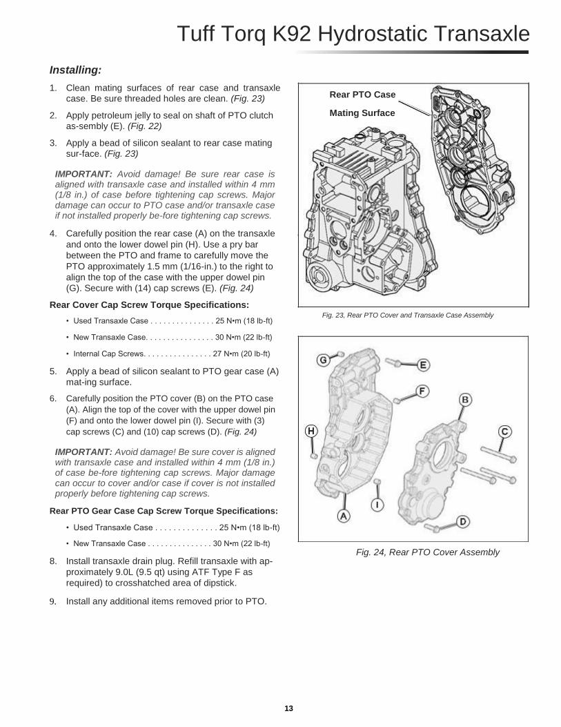
Installing: 1. Clean mating surfaces of rear case and transaxle
case. Be sure threaded holes are clean. (Fig. 23) 2. Apply petroleum jelly to seal on shaft of PTO clutch
as-sembly (E). (Fig. 22) 3. Apply a bead of silicon sealant to rear case mating
sur-face. (Fig. 23)
IMPORTANT: Avoid damage! Be sure rear case is aligned with transaxle case and installed within 4 mm (1/8 in.) of case before tightening cap screws. Major damage can occur to PTO case and/or transaxle case if not installed properly be-fore tightening cap screws.
4. Carefully position the rear case (A) on the transaxle
and onto the lower dowel pin (H). Use a pry bar
between the PTO and frame to carefully move the
PTO approximately 1.5 mm (1/16-in.) to the right to
align the top of the case with the upper dowel pin
(G). Secure with (14) cap screws (E). (Fig. 24) Rear Cover Cap Screw Torque Specifications:
• Used Transaxle Case . . . . . . . . . . . . . . . 25 N•m (18 lb-ft)
• New Transaxle Case. . . . . . . . . . . . . . . . 30 N•m (22 lb-ft)
• Internal Cap Screws. . . . . . . . . . . . . . . . 27 N•m (20 lb-ft)
5. Apply a bead of silicon sealant to PTO gear case (A)
mat-ing surface. 6. Carefully position the PTO cover (B) on the PTO case
(A). Align the top of the cover with the upper dowel pin
(F) and onto the lower dowel pin (I). Secure with (3)
cap screws (C) and (10) cap screws (D). (Fig. 24)
IMPORTANT: Avoid damage! Be sure cover is aligned with transaxle case and installed within 4 mm (1/8 in.) of case be-fore tightening cap screws. Major damage can occur to cover and/or case if cover is not installed properly before tightening cap screws.
Rear PTO Gear Case Cap Screw Torque Specifications:
• Used Transaxle Case . . . . . . . . . . . . . . 25 N•m (18 lb-ft)
• New Transaxle Case . . . . . . . . . . . . . . . 30 N•m (22 lb-ft)
8. Install transaxle drain plug. Refill transaxle with ap-
proximately 9.0L (9.5 qt) using ATF Type F as
required) to crosshatched area of dipstick.
9. Install any additional items removed prior to PTO.
Rear PTO Case
Mating Surface Fig. 23, Rear PTO Cover and Transaxle Case Assembly
Fig. 24, Rear PTO Cover Assembly
13

Rear PTO Removal and Installation
NOTE: Approximate capacity of hydrostatic power train is 9.0L (9.5 qt) for 4WD w/rear PTO.
Removing:
CAUTION: Avoid Injury! Allow transaxle to cool before
drain-ing fluid. Hot fluid can cause serious burns 1. Remove plug (AA) to drain oil from transaxle. (Fig. 25)
Fig. 25, Rear PTO Gear Case Cover 2. Remove (14) cap screws (AC) and PTO gear case
cover assembly (AD). (Fig. 25)
NOTE: Remember to install two different sized cap screws in original holes as removed.
3 Remove PTO drive gear (G). Inspect parts and
replace as necessary. (Fig. 26) 4. Remove and replace oil seal (S) from cover. Install
new seal into cover with the closed side of the
seal into the bore first. Use a disk driver to push
seal to bottom of bore. (Fig. 26)
Fig. 26, PTO Rear Case Cover
Disassembly and Assembly: 1. Remove cover from PTO gear case (C). (Fig. 27) 2. Remove cap screw (A) and plate (B), and pull
shifter shaft (E) from PTO gear case (C). Replace
O-ring on shifter shaft and apply thin coating of
clean hydraulic oil, before reinstalling. (Fig. 27)
Fig. 27, Rear PTO Gear Case Assembly
14
Tuff Torq K92 Hydrostatic Transaxle
3. Remove shift collar (F) and shifter fork (N)
assembly together. (Fig. 27)
NOTE: If shift collar replacement is necessary, the rear PTO idler gear and rear PTO input gear must be replaced also. The three gears are available as a set.
4. Remove tow relief valve (L) if necessary. Remove
and replace O-ring. (Fig. 28)
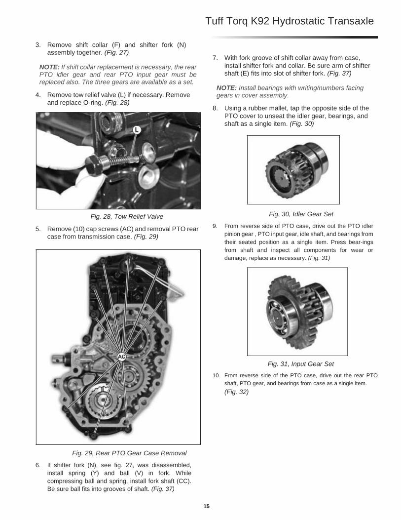
Fig. 28, Tow Relief Valve 5. Remove (10) cap screws (AC) and removal PTO rear
case from transmission case. (Fig. 29)
Fig. 29, Rear PTO Gear Case Removal 6. If shifter fork (N), see fig. 27, was disassembled,
install spring (Y) and ball (V) in fork. While
compressing ball and spring, install fork shaft (CC).
Be sure ball fits into grooves of shaft. (Fig. 37)
7. With fork groove of shift collar away from case,
install shifter fork and collar. Be sure arm of shifter
shaft (E) fits into slot of shifter fork. (Fig. 37)
NOTE: Install bearings with writing/numbers facing gears in cover assembly.
8. Using a rubber mallet, tap the opposite side of the
PTO cover to unseat the idler gear, bearings, and
shaft as a single item. (Fig. 30)
Fig. 30, Idler Gear Set 9. From reverse side of PTO case, drive out the PTO idler
pinion gear , PTO input gear, idle shaft, and bearings from
their seated position as a single item. Press bear-ings
from shaft and inspect all components for wear or
damage, replace as necessary. (Fig. 31)
Fig. 31, Input Gear Set 10. From reverse side of the PTO case, drive out the rear PTO
shaft, PTO gear, and bearings from case as a single item.
(Fig. 32)
15

Rear PTO Removal and Installation (continued)
Fig. 32, Rear PTO Shaft Assembly 11. Remove press bearing (S) from the PTO shaft (X); then,
remove PTO gear (T), snap rings (Z), and press bearing
(W) from PTO shaft. Inspect all components for
wear or damage, replace as necessary. (Fig. 33)
Fig. 33, Rear PTO Shaft Disassembly 12. Remove press bearing (M) from idler shaft (P). Remove
washer (N), PTO input gear (R), and idler pinion gear (O).
Remove press bearing (U) and remove washer (Q) from
idler shaft (P). Inspect all components for wear or dam-age,
replace as necessary. (Fig. 34)
Fig. 34, Rear PTO Pinion/Input Gear Disassembly
NOTE: If rear PTO input gear (R), see fig. 34, replacement is
necessary, the shift collar (F), see fig. 36, and rear PTO idler
gear (G), see fig. 35, must be replaced also. The three gears are
available as a set. Rear PTO gear (T), see fig. 33, and rear PTO
idler pinion (O), see fig. 34, must be replaced as a set.
13. Remove snap ring (L), idler gear (G), snap ring (H),
press bearing (I), and press bearing (K) from shaft
(J). Inspect all components for wear or damage,
replace as neces-sary. (Fig. 35)
NOTE: Recall writing/numbers on all outer bearing
races, and install bearings in reverse order as removal.
Fig. 35, Rear PTO Idler Gear Disassembly 14. If necessary, remove ball switch (W) and O-ring.
(Fig. 36) • If removed, install O-rings and ball switches (W). DO
NOT overtighten. Tighten to 34 N•m (25 lb-ft).
Fig. 36, Ball Switches 15. Inspect all parts and replace as necessary.
Assembly is reverse order of disassembly.
16
Tuff Torq K92 Hydrostatic Transaxle
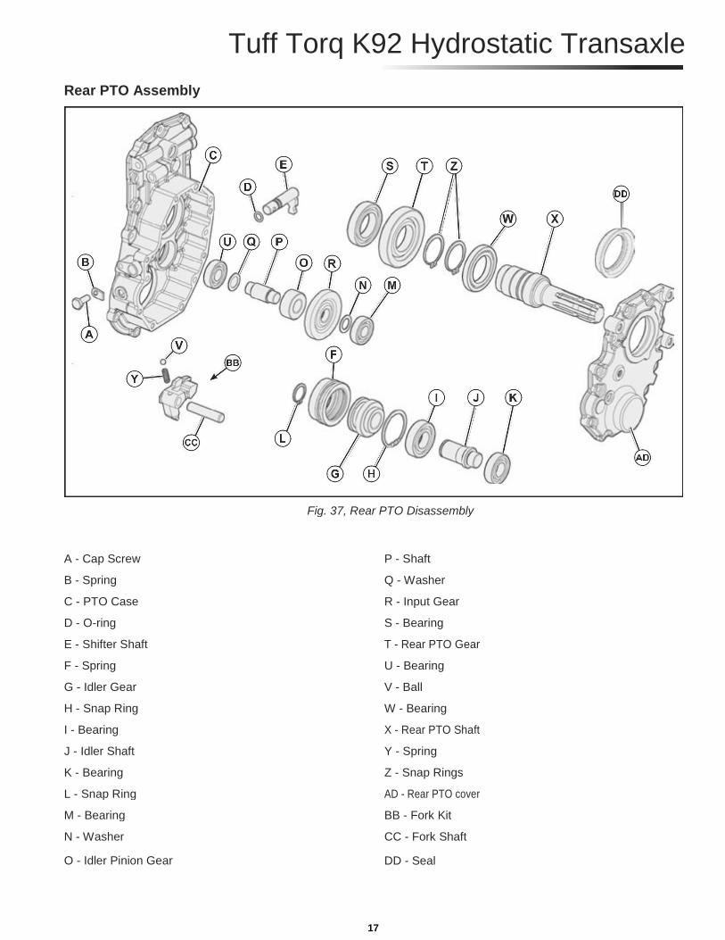
Rear PTO Assembly
Fig. 37, Rear PTO Disassembly
A - Cap Screw P - Shaft
B - Spring Q - Washer
C - PTO Case R - Input Gear
D - O-ring S - Bearing
E - Shifter Shaft T - Rear PTO Gear
F - Spring U - Bearing
G - Idler Gear V - Ball
H - Snap Ring W - Bearing
I - Bearing X - Rear PTO Shaft
J - Idler Shaft Y - Spring
K - Bearing Z - Snap Rings
L - Snap Ring AD - Rear PTO cover
M - Bearing BB - Fork Kit
N - Washer CC - Fork Shaft
O - Idler Pinion Gear DD - Seal
17
Rear PTO Removal and Installation (continued)
Installing:
NOTE: Installation is done in the reverse order of diassembly. Additional information can be found by refering to the “Rear PTO Removal and Installation” removal section, starting on page 14.
1. Clean mating surfaces of cover (AD) and gear case
(C). Be sure threaded holes are clean. (Fig. 37) 2. If removed, install gear sets in the reverse order of
their disassembly. (Fig. 37) 3. Apply a bead of silicon sealant to any mating surfaces
to be assembled.
IMPORTANT: Avoid damage! Carefully lower cover assem-
bly onto case, making sure bearings fit into bores and gears
mesh properly. Be sure cover is installed within 3 mm (1/8
in.) of case before tightening all cap screws to 25 N•m (18 lb-
ft). Major damage can occur to cover and/or case if not
properly aligned before tightening cap screws. 4. Install PTO assembly on the two alignment
bushings, and tighten tenF), and three M8 x 50 (E)
cap screws to specification below. 5. Install transaxle drain plug. Refill transaxle with
approxi-mately 9.0L (9.5 qt) using ATF Type F to
crosshatched area of dipstick. Specifications:
• M8 Bolts. . . . . . . . . . . . . . . . . . . . . . . . . 24 N•m (18 lb-ft)
• M12 Bolts. . . . . . . . . . . . . . . . . . . . . . . . 54 N•m (40 lb-ft)
18

Tuff Torq K92 Hydrostatic Transaxle
Differential Lock Shaft Disassembly and Assembly
Fig. 38, Differential Lock Shaft Disassembly
A - Snap Ring (2 used) H - Roll Pin B - Spring I - Shift Collar C - Sleeve (2 used) J - Cap Screw D - Fork K - Plate E - Shaft L - Fulcrum, Differential Lock F - Spring M - Washer G - Washer N - Cotter Pin
O - Seal 1. Remove roll pin (H), washer (G), and spring (F). (Fig. 38)
2. Remove snap rings (A), sleeves (C), spring (B), shaft (E), and fork (D). (Fig. 38)
3. Inspect shaft (E) and fork for wear or damage.
Replace parts as necessary. (Fig. 38)
NOTE: Installation is done in the reverse order of removal.
NOTE: Install long hub of fork towards transaxle.
CAUTION: Avoid Injury! Springs are under compression. Carefully remove roll pin and release spring force slowly to prevent personal injury.
19
Differential (2WD) Disassembly and Assembly
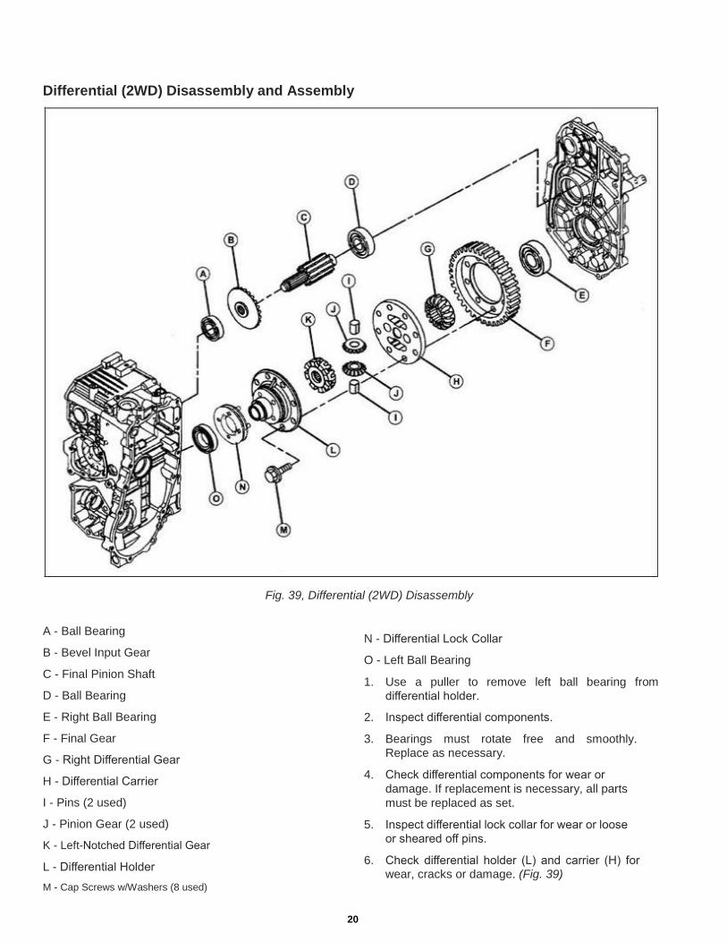
A - Ball Bearing B - Bevel Input Gear C - Final Pinion Shaft D - Ball Bearing E - Right Ball Bearing F - Final Gear G - Right Differential Gear H - Differential Carrier I - Pins (2 used) J - Pinion Gear (2 used) K - Left-Notched Differential Gear L - Differential Holder M - Cap Screws w/Washers (8 used)
Fig. 39, Differential (2WD) Disassembly
N - Differential Lock Collar
O - Left Ball Bearing
1. Use a puller to remove left ball bearing from
differential holder.
2. Inspect differential components.
3. Bearings must rotate free and smoothly.
Replace as necessary.
4. Check differential components for wear or
damage. If replacement is necessary, all parts
must be replaced as set.
5. Inspect differential lock collar for wear or loose
or sheared off pins.
6. Check differential holder (L) and carrier (H) for wear, cracks or damage. (Fig. 39)
20

Tuff Torq K92 Hydrostatic Transaxle
7. Inspect final gear (F) for worn or damaged teeth.
(Fig. 39) 8. Inspect ball bearings (A and D) for smooth rotation.
(Fig. 39)
NOTE: Final pinion shaft (C) and final gear (F) must be re-placed as a set. Bevel input gear (B) and bevel input pinion (not shown) must be replaced as a set.
9. Check bevel input gear (B) and final pinion shaft (C) for
worn or damaged condition. Replace parts as necessary.
(Fig. 39)
10. Install final gear on differential holder and carrier
with the deeper offset of gear center away from the
holder. Tighten eight differential cap screws (M) to
88 N•m (65 lbft). 11. Install differential lock collar (N) and left and right
bear-ings (O). Push bearing tight against shoulder of
differen-tial holder. (Fig. 39) 12. Install remaining components.
NOTE: Use medium strength thread lock and sealer.
Differential (4WD) Disassembly and Assembly
Fig. 40, Differential (4WD) Disassembly
A - Ball Bearing I - Washer (2 used) B - Bevel Input Gear J - Pinion Gear (2 used) C - Final Pinion Shaft K - Differential Pinion Shaft D - Ball Bearing L - Left-Notched Differential Gear E - Ball Bearing (2 used) M - Final Gear F - Differential Holder, Right N - Differential Holder, Left G - Liner (2 used) O - Washers (8 used) H - Right Differential Gear P - Cap Screws (8 used)
Q - Differential Lock Collar 21
Differential (4WD) Disassembly and Assembly (continued) 1. Use a puller to remove ball bearings (E) from
differential holders (F and N). (Fig. 40) 2. Inspect differential components. 3. Bearings must rotate free and smoothly.
Replace as necessary. 4. Check differential components for wear or
damage. If replacement is necessary, all parts
must be replaced as set. 5. Inspect differential lock collar for wear or loose
or sheared off pins. 6. Check differential holders (F and N) and differential
pinion shaft (K) for wear, cracks or damage. (Fig. 40) 7. Inspect final gear (M) for worn or damaged teeth.
NOTE: Pinion gears (J) (2 used), washers (I) (2 used), and
dif-ferential pinion shaft (K) must be replaced as a set. 8. Inspect ball bearings (A and D) for smooth rotation.
NOTE: Final pinion shaft (C) and final gear (M) must be re-placed as a set. Bevel input gear (B) and bevel input pinion (not shown) must be replaced as a set.
9. Check bevel input gear (B) and final pinion shaft (C) for
worn or damaged condition. Replace parts as necessary. 10. Install final gear on differential holder and carrier
with the deeper offset of gear center away from the
holder. Tighten eight differential cap screws (P) to
88 N•m (65 lbft). 11. Install differential lock collar (Q) and left bearing
(E). Push bearing tight against shoulder of
differential holder. 12. Install remaining components.
NOTE: Use medium strength thread lock and sealer.
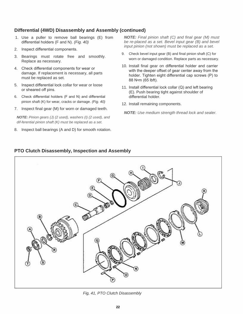
PTO Clutch Disassembly, Inspection and Assembly
Fig, 41, PTO Clutch Disassembly
22

Tuff Torq K92 Hydrostatic Transaxle
A - Ball Bearing B - Snap Ring C - Clutch Shaft D - Needle Bearing E - Washer F - O-ring G - Piston H - Spring I - Washer J - Snap Ring K - Input Shaft Collar L - Snap Ring M - Thick Steel Plate N - Friction Plate O - Spring P - Pin Q - Steel Plate R - Clutch Gear/Hub S - Washer T - Seal Ring
1. Remove PTO clutch assembly. (See “PTO Brake
Removal and Installation” on page 6.) 2. Remove large snap ring and thick steel plate. 3. Remove parts.
NOTE: Friction plates, springs, steel plates and pins must be replaced as a set.
4. Replace clutch gear/hub if brake surface is badly
scored or teeth are chipped or damaged.
CAUTION: Avoid Injury! Piston is under spring force. Use care during disassembly.
5. Remove piston from clutch gear/hub. Use a transmis-
sion gear spacer (X) to compress spring (U) and washer
(V) in a vise. Remove snap ring (W) and slowly release force of spring. (Fig. 42)
6. Remove remaining clutch parts. 7. Check bearings for smooth rotation. 8. Inspect clutch gear for worn or damaged teeth. 9. Check inner piston bore for scoring or wear.
Fig. 42, Clutch Disassembly
10. Check steel plates for scoring, discoloration,
warping or wear. 11. Replace worn or damaged springs. 12. Check input shaft collar for burrs, wear or
damaged teeth or splines. 13. Check clutch pack wear. Assemble parts.
Fig. 43, Clutch Disassembly
14. Put clutch gear/hub on bench so steel and friction plates
are against snap ring. Measure clearance between inner
steel plate and bottom of clutch gear/hub. 15. If clearance measures 2.7 mm (0.106 in.) or
more, re-place PTO clutch plates. 16. Apply clean hydraulic oil to all parts.
NOTE: Installation is done in the reverse order of removal. 23

4WD Output Disassembly and Assembly 1. Drain transaxle.
CAUTION: Avoid Injury! Allow transaxle to cool before
drain-ing fluid. Hot fluid can cause serious burns. 2. Remove bolt/washer (I, J) and drain the 4WD gear box. 3. Remove (11) bolts (H), bolt (AK), and bolt (AH) from
4WD cover. 4. Remove 4WD cover (A).
NOTE: To avoid damage, during separation, to the cover
and/or the gear box, use the pry points shown in fig. 44.
Fig. 44, 4WD Cover Removal
5. Remove the drive gear (AC) from motor shaft.
6. Remove the first press bearing (E), gear (Y), washer (Z),
and gear (AA) from 4WD reduction shaft (X). Remove
4WD reduction shaft (X), and the second press bearing
(E) from the 4WD gear box as a single item. (Fig. 46) 7. Remove press bearing (E) from 4WD reduction shaft (X).
NOTE: When reinstalling, take care to place gears in their
original order; with the thicker gear in front (with raised sur-
face towards the bearing) and the thinner gear behind.
Fig. 46, 4WD Cover Removal
8. Remove snap rings (V) and (AM); then, gear (R) from shaft
(S). Remove snap ring (AN) and remove (S, T, U, V, W,
and AO) as a single item from the 4WD gear case. 9. Remove press bearing (AO), collar (W), snap ring (V),
press bearing (U), and collar (T) from shaft (S). (Fig. 47)
NOTE: Flat end of shift collar goes toward bearing.
10. Clean bearings in a suitable solvent. Dry with
com-pressed air.
IMPORTANT: Avoid damage! DO NOT spin bearing using compressed air. Damage to bearing balls, cage, and races could result.
11. Inspect bearings for discolored, burned, balls and/or
races. Check balls and races for spalling or cracking.
Roll bearing by hand to check for rough turning or
excessive looseness or play between balls and
races. Replace bear-ings as required.
Fig. 45, 4WD Cover Removal
NOTE: Snap ring (AD) on motor shaft does not need to be removed for the 4WD gear case removal. Unless replacement is necessary. (Fig. 52).
Fig. 47, 4WD Cover Removal 24
Tuff Torq K92 Hydrostatic Transaxle
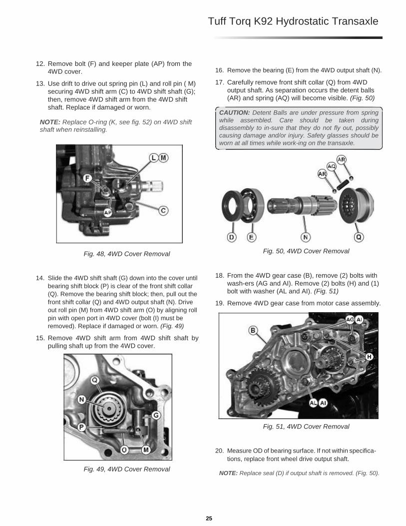
12. Remove bolt (F) and keeper plate (AP) from the
4WD cover. 13. Use drift to drive out spring pin (L) and roll pin ( M)
securing 4WD shift arm (C) to 4WD shift shaft (G);
then, remove 4WD shift arm from the 4WD shift
shaft. Replace if damaged or worn.
NOTE: Replace O-ring (K, see fig. 52) on 4WD shift shaft when reinstalling.
Fig. 48, 4WD Cover Removal
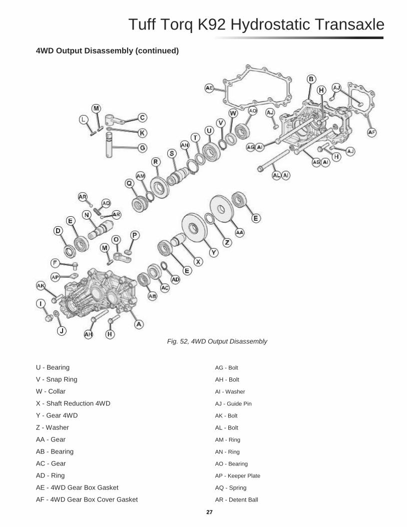
14. Slide the 4WD shift shaft (G) down into the cover until
bearing shift block (P) is clear of the front shift collar
(Q). Remove the bearing shift block; then, pull out the
front shift collar (Q) and 4WD output shaft (N). Drive
out roll pin (M) from 4WD shift arm (O) by aligning roll
pin with open port in 4WD cover (bolt (I) must be
removed). Replace if damaged or worn. (Fig. 49) 15. Remove 4WD shift arm from 4WD shift shaft by
pulling shaft up from the 4WD cover.
Fig. 49, 4WD Cover Removal
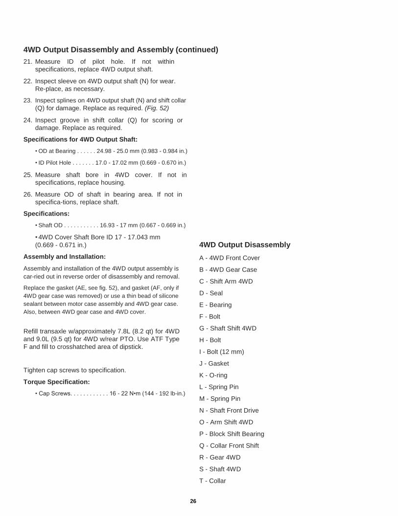
16. Remove the bearing (E) from the 4WD output shaft (N). 17. Carefully remove front shift collar (Q) from 4WD
output shaft. As separation occurs the detent balls
(AR) and spring (AQ) will become visible. (Fig. 50)
CAUTION: Detent Balls are under pressure from spring
while assembled. Care should be taken during
disassembly to in-sure that they do not fly out, possibly
causing damage and/or injury. Safety glasses should be
worn at all times while work-ing on the transaxle.
Fig. 50, 4WD Cover Removal
18. From the 4WD gear case (B), remove (2) bolts with
wash-ers (AG and AI). Remove (2) bolts (H) and (1)
bolt with washer (AL and AI). (Fig. 51) 19. Remove 4WD gear case from motor case assembly.
Fig. 51, 4WD Cover Removal
20. Measure OD of bearing surface. If not within specifica-
tions, replace front wheel drive output shaft.
NOTE: Replace seal (D) if output shaft is removed. (Fig. 50).
25
4WD Output Disassembly and Assembly (continued) 21. Measure ID of pilot hole. If not within
specifications, replace 4WD output shaft. 22. Inspect sleeve on 4WD output shaft (N) for wear.
Re-place, as necessary. 23. Inspect splines on 4WD output shaft (N) and shift collar
(Q) for damage. Replace as required. (Fig. 52) 24. Inspect groove in shift collar (Q) for scoring or
damage. Replace as required. Specifications for 4WD Output Shaft:
• OD at Bearing . . . . . . 24.98 - 25.0 mm (0.983 - 0.984 in.)
• ID Pilot Hole . . . . . . . 17.0 - 17.02 mm (0.669 - 0.670 in.)
25. Measure shaft bore in 4WD cover. If not in
specifications, replace housing. 26. Measure OD of shaft in bearing area. If not in
specifica-tions, replace shaft. Specifications:
• Shaft OD . . . . . . . . . . . 16.93 - 17 mm (0.667 - 0.669 in.)
• 4WD Cover Shaft Bore ID 17 - 17.043 mm (0.669 - 0.671 in.)
Assembly and Installation: Assembly and installation of the 4WD output assembly is
car-ried out in reverse order of disassembly and removal. Replace the gasket (AE, see fig. 52), and gasket (AF, only if
4WD gear case was removed) or use a thin bead of silicone
sealant between motor case assembly and 4WD gear case.
Also, between 4WD gear case and 4WD cover.
Refill transaxle w/approximately 7.8L (8.2 qt) for 4WD
and 9.0L (9.5 qt) for 4WD w/rear PTO. Use ATF Type
F and fill to crosshatched area of dipstick.
Tighten cap screws to specification. Torque Specification:
• Cap Screws. . . . . . . . . . . . 16 - 22 N•m (144 - 192 lb-in.)
4WD Output Disassembly A - 4WD Front Cover B - 4WD Gear Case C - Shift Arm 4WD D - Seal E - Bearing F - Bolt G - Shaft Shift 4WD H - Bolt I - Bolt (12 mm) J - Gasket K - O-ring L - Spring Pin M - Spring Pin N - Shaft Front Drive O - Arm Shift 4WD P - Block Shift Bearing Q - Collar Front Shift R - Gear 4WD S - Shaft 4WD T - Collar
26
Tuff Torq K92 Hydrostatic Transaxle
4WD Output Disassembly (continued)
Fig. 52, 4WD Output Disassembly
U - Bearing AG - Bolt V - Snap Ring AH - Bolt W - Collar AI - Washer X - Shaft Reduction 4WD AJ - Guide Pin Y - Gear 4WD AK - Bolt Z - Washer AL - Bolt AA - Gear AM - Ring AB - Bearing AN - Ring AC - Gear AO - Bearing AD - Ring AP - Keeper Plate AE - 4WD Gear Box Gasket AQ - Spring AF - 4WD Gear Box Cover Gasket AR - Detent Ball
27

Hydrostatic Transmission 2WD and 4WD Hydrostatic Transmission Removal: 1. Remove charge pump. (See “Charge Pump Removal
and Installation” on page 2)
IMPORTANT: Avoid damage! Do not drop or damage pump
valve plate when removing center valve block assembly. Do
not nick or scratch lapped or machined surfaces of the valve
plates or cylinder block components. The slightest damage
can cause poor performance.
Fig. 53, 2WD Shown (4WD similar) 2. Remove cap screws (A) — leaving in place 2 cap screws
(D). Carefully remove center valve block (B) and
motor assembly from transaxle.
3. Replace gasket (C) if torn or damaged.
Hydrostatic Transmission Motor Removal:
Fig. 54, 2WD Shown (4WD similar)
2WD Shown 1. Remove retaining ring (B), bevel input pinion (C),
and ball bearing (A). 2. Inspect bearing for smooth rotation.
NOTE: Bevel input pinion and bevel input gear must be re-placed as a set.
3. Check pinion for wear or damage. 4. Replace retaining ring if ring is distorted during
remov-al.
28

Tuff Torq K92 Hydrostatic Transaxle
Hydrostatic Transmission Motor Disassembly and Assembly (2WD)
A - Cap Screw (2
pieces) B - Seal Cap C - Snap Ring D - Snap Ring E - Washer F - Ball Bearing G - Motor Case H - Locating Sleeve (2
used) I - Motor Shaft J - Center Valve Block Assembly K - Locating Pin L - Motor Valve Plate M - Snap Ring N - Washer O - Spring P - Cylinder Block Q - Shim R - Piston Spring
Fig. 55, Hydrostatic Transmission Motor Disassembly (2WD)
S - Piston
T - Gasket
U - Thick Thrust Plate
V - Thrust Bearing
W- Bushing
X - Thin Thrust Plate
IMPORTANT: Avoid damage! Do not drop or damage mo-tor valve plate when removing motor assembly. Do not nick or scratch lapped or machined surfaces of the valve plate or cylinder block components. The slightest damage can cause poor performance.
1. Remove two cap screws (A). (Fig. 55)
IMPORTANT: Avoid damage! Keep pistons (S) matched
with bore of cylinder block (P). Do not interchange motor
pistons and valve plate (L) with pump pistons and valve
plate. Pistons and cylinder blocks are a matched set.
2. Remove cylinder block assembly.
NOTE: Motor rotating components must be replaced as a set.
29

Hydrostatic Transmission Motor Disassembly and Assembly (2WD) (continued) 3. Inspect rotating components:
NOTE: Scoring is fine scratches or grooves cut into the highly
machined surface. When the scratches can be detected by feel
using a lead pencil or fingernail, the part must be replaced. 4. Check valve plate and cylinder block for grooves,
scor-ing, discoloration or pitting. 5. Check for free movement of pistons in cylinder bore. 6. Check pistons for flat areas, scoring or discoloration. 7. Thrust bearing (V) must rotate freely. (Fig. 55)
NOTE: Thin thrust plate (X), bushing (W) and motor case (G) must be replaced as a set. (Fig. 55)
8. Inspect thin thrust washer for wear or damage.
Replace as necessary.
IMPORTANT: Avoid damage! Do not damage ball bearing (F) when removing seal cap (B).
9. Remove seal cap (B) and snap ring (C) to remove
shaft assembly components. 10. Inspect bushing (W), thrust bearing (V) and shaft (I) for
wear or damage. Replace if necessary. (Fig. 55)
NOTE: Apply silicon sealant to outer edge of new seal cap. Install seal cap until cap is approximately 4 mm (5/32 in.) be-low surface of motor case.
11. Assemble parts in reverse order of removal.
NOTE: Use petroleum jelly to hold valve plate in position. • Put motor valve plate (L) on center valve block. Make
sure bronze surface is away from valve block and notch
in valve plate fits on locating pin of valve block.
IMPORTANT: Avoid damage! Apply clean hydraulic oil to all mating surfaces.
IMPORTANT: Avoid damage! Pump and motor valve plates are not interchangeable. The pump valve plate has two lead-ing grooves into two of the slotted ports. The motor valve plate (L) has no leading grooves.
NOTE: Motor case will seem springy because the springs
in-side the cylinder block are being compressed.
30

Tuff Torq K92 Hydrostatic Transaxle
Hydrostatic Transmission Motor Disassembly and Assembly (4WD)
A - Cap Screw (2
pieces) B - Snap Ring
C - Snap Ring D - Ball Bearing E - Motor Case F - Locating Sleeve (2
used) G - Motor Shaft H - Center Valve Block Assembly I - Locating Pin J - Motor Valve Plate K - Snap Ring L - Washer M - Spring N - Cylinder Block O - Shim P - Piston Spring Q - Piston
Fig. 56, Hydrostatic Transmission Motor Disassembly (4WD)
R - Gasket
S - Thick Thrust Plate
T - Thrust Bearing
U - Bushing
V - Thin Thrust Plate
1. Remove 4WD gear box assembly. (See “4WD
Output Disassembly and Assembly” on page 24.)
IMPORTANT: Avoid damage! Do not drop or damage mo-tor valve plate when removing motor assembly. Do not nick or scratch lapped or machined surfaces of the valve plate or cylinder block components. The slightest damage can cause poor performance.
2. Remove two cap screws (A). (Fig. 56)
IMPORTANT: Avoid damage! Keep pistons (Q) matched
with bore of cylinder block (N). Do not interchange motor
pistons and valve plate (J) with pump pistons and valve
plate. Pistons and cylinder blocks are a matched set.
3. Remove cylinder block assembly.
NOTE: Motor rotating components must be replaced as a set.
31

Hydrostatic Transmission Motor Disassembly and Assembly (4WD) (continued) 4. Inspect rotating components:
NOTE: Scoring is fine scratches or grooves cut into the highly
machined surface. When the scratches can be detected by feel
using a lead pencil or fingernail, the part must be replaced. 5. Check valve plate and cylinder block for grooves,
scor-ing, discoloration or pitting. 6. Check for free movement of pistons in cylinder bore. 7. Check pistons for flat areas, scoring or discoloration. 8. Thrust bearing (T) must rotate freely. (Fig. 56)
NOTE: Thin thrust plate (V), bushing (U) and motor case (E) must be replaced as a set. (Fig. 56)
9. Inspect thin thrust plate (V) for wear or damage.
Re-place as necessary.
IMPORTANT: Avoid damage! Do not damage ball bearing (D) when removing snap ring (B).
10. Remove snap ring (B) to remove shaft assembly
compo-nents. 11. Inspect bushing (U), thrust bearing (T) and shaft (G)
for wear or damage. Replace if necessary. (Fig. 56)
IMPORTANT: Avoid damage! Apply clean hydraulic oil to all mating surfaces.
12. Assemble parts in reverse order of removal.
NOTE: Use petroleum jelly to hold valve plate in position.
• Put motor valve plate (J) on center valve block. Make
sure bronze surface is away from valve block and notch
in valve plate fits on locating pin of valve block.
IMPORTANT: Avoid damage! Pump and motor valve plates are not interchangeable. The pump valve plate has two lead-ing grooves into two of the slotted ports. The motor valve plate (J) has no leading grooves.
NOTE: Motor case will seem springy because the springs
in-side the cylinder block are being compressed.
32

Tuff Torq K92 Hydrostatic Transaxle
Center Valve Block Disassembly and Assembly
Fig. 57, Center Valve Block Disassembly
A - Holder K - Top Plug B - Spring L - O-ring C - Ball M - O-ring D - Push Pin N - Washer E - O-ring O - Shim (0.5) F - Seal P - Shim (0.2) G - O-ring Q - Spring H - Back-up Ring R - Charge Pressure Relief Valve Plunger I - O-ring S - Reverse Check Valve J - Forward Check Valve T - Seat
33

Center Valve Block Disassembly and Assembly (continued) U - Center Valve Block V - Needle Bearing (2 used) W- Locating Pin (2 used) X - Pump Valve Plate Y - Anti-Cavitation Valve Body Z - Backup Ring AA- O-ring AB- Ball AC- Ball Holder AD- Spring AE- Retainer AF- Motor Valve Plate
NOTE: Remove motor assembly if necessary to inspect nee-dle bearing. (See “Hydrostatic Transmission Motor Removal:” on page 28.)
1. Remove and inspect directional check valves.
IMPORTANT: Avoid damage! The reverse check valve must be installed in the left port. The check valve can be identified by a small orifice drilled into a land between the two sets of valve passageways.
2. Replace locator pins if missing or damaged. 3. Inspect needle bearings for wear or damage. If
bearings are replaced, install new bearings with the
stamped end away from center valve block. 4. Push bearings into bore until end of bearing is
approxi-mately 3 mm (7/64 in.) above the surface of
the valve block. 5. Inspect anti-cavitation valve assemblies.
NOTE: Screens may be located in bores of transaxle case. 6. Check suction screens for blockage. 7. Carefully pull anti-cavitation valve body from
center valve block so as not to lose parts. 8. Replace parts as necessary. 9. Apply oil to O-rings and push assembly to bottom
of bore. 10. Inspect center valve block where charge pump
contacts block for scoring. 11. Replace center valve block if necessary.
NOTE: Scoring is fine scratches or grooves cut into the highly
machined surface. When the scratches can be detected by feel
using a lead pencil or fingernail, the part must be replaced.
12. Inspect valve plate for grooves, scoring, discoloration
or pitting.
IMPORTANT: Avoid damage! Pump and motor valve plates are not interchangeable. The pump valve plate has two lead-ing grooves into two of the slotted ports. The motor valve plate has no leading grooves.
13. Put pump valve plate on center valve block. Make
sure bronze surface is away from valve block and
notch in valve plate fits on locating pin of valve block.
NOTE: Use petroleum jelly to hold valve plate in position. 14. Remove plug to inspect charge pressure relief
valve parts. 15. Check plunger for nicks, wear or damage. 16. Inspect plunger seat in center valve block. Remove
any obstructions and replace center valve block if
seat is worn or damaged.
Hydrostatic Transmission Motor Installation
NOTE: Replace retaining ring (D) if ring is distorted during removal.
Fig. 58, Hydrostatic (2WD) Motor 1. Secure motor housing assembly (A) and gasket (F)
to center valve block (B) with (2) lower capscrews
(G). In-stall ball bearing (C) and bevel input pinion
(E) — secure with retaining ring (D).
34

Hydrostatic Transmission Installation
IMPORTANT: Avoid damage! Do not drop or damage pump
valve plate when removing center valve block assembly. Do
not nick or scratch lapped or machined surfaces of the valve
plates or cylinder block components. The slightest damage
can cause poor performance.
Tuff Torq K92 Hydrostatic Transaxle
1. Install gasket (C). (Fig. 59)
2. Install center valve block (B) and motor assembly to
transaxle housing and secure with cap screws (A).
(Fig. 59)
• Tighten cap screws (A) to 39 N•m (29 lb-ft).
3. Install charge pump. (See “Charge Pump Removal
and Installation” on page 2)
Fig. 59, Hydrostatic, 2WD (4WD similar) Motor Install
Hydrostatic Pump Inspection
Fig. 60, Hydrostatic Pump Disassembly
35

Hydrostatic Pump Inspection (continued) A - Washers B - Piston Spring (7 used) C - Snap Ring D - Cylinder Block E - Washer F - Spring G - Piston (7 used) H - Thick Thrust Plate I - Thrust Bearing J - Thin Thrust Plate
IMPORTANT: Avoid damage! Keep pistons matched with bore of cylinder block. Do not interchange motor pistons and valve plate with pump pistons and valve plate. Pistons and cylinder blocks are a matched set.
1. Spring is compressed. Apply an external force to
com-press spring farther before removing snap
ring. Then slowly remove external force. 2. Remove parts from transaxle as necessary.
NOTE: Pump rotating components must be replaced as a set. Thin thrust plate must be replaced as a set with the pump swash plate and bushing.
3. Check cylinder block for grooves, scoring,
discoloration or pitting.
NOTE: Scoring is fine scratches or grooves cut into the highly
machined surface. When the scratches can be detected by feel
using a lead pencil or fingernail, the part must be replaced. 4. Check for free movement of pistons in cylinder bores. 5. Check pistons for flat areas, scoring or
discoloration. Thrust bearing must rotate freely. For inspection of pump valve plate, refer to “Center
Valve Block Disassembly and Assembly:” on page 33.
Transaxle Disassembly 1. Remove control arm damper. (See “Control Arm
and Damper Removal and Installation” on page 1.) 2. Remove hydrostatic transmission and pump. (See “Hy-
drostatic Transmission 2WD and 4WD” on page 35.) 3. Remove axle housings. (See “Rear Axle Assembly Re-
moval and Installation” on page 41, and See “Rear Axle
Assembly - Disassembly and Assembly” on page 42.) 4. Remove brakes. (See “Brakes Removal and
Installation” page 43.)
5. Remove PTO idler shaft assembly (C), snap ring
(E), PTO gear (D) (or rear drive gear set).
Fig. 61, Without Rear PTO Option
Fig. 62, With Rear PTO Option 6. Remove PTO brake shoe (B) and clutch (A). (See
“PTO Brake Removal and Installation” on page 6.) 7. Remove large snap ring (H) and input shaft assembly. 8. Remove large snap ring (L), small snap rings (G and K)
washers (M and J), and ball bearing (I) from input shaft
(F). (Fig. 63)
36
Tuff Torq K92 Hydrostatic Transaxle
Transaxle Disassembly (continued)
F - Input Shaft
G - Snap Ring
H - Snap Ring
I - Ball Bearing
J - Washer
K - Snap Ring
L - Snap Ring
M - Washer
Fig. 63, Transaxle Input Shaft Disassembly
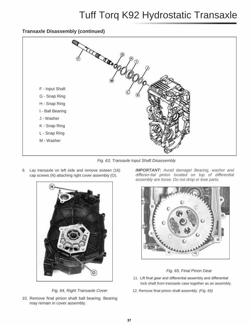
9. Lay transaxle on left side and remove sixteen (16)
cap screws (N) attaching right cover assembly (O).
IMPORTANT: Avoid damage! Bearing, washer and differen-tial pinion located on top of differential assembly are loose. Do not drop or lose parts.
Fig. 65, Final Pinon Gear
11. Lift final gear and differential assembly and differential
lock shaft from transaxle case together as an assembly.
Fig. 64, Right Transaxle Cover 12. Remove final pinion shaft assembly. (Fig. 65) 10. Remove final pinion shaft ball bearing. Bearing
may remain in cover assembly. 37

Transaxle (Right Cover) Disassembly and Assembly
A - Swash Plate Bearing B - Washer C - Bushing D - Spring E - Cover F - Snap Ring G - Washer H - Cap Screw I - Washer J - Control Arm K - Nut L - Washer M - Pivot Stud N - O-ring O - Eccentric Adjust Fulcrum P - Swash Plate
Fig. 66, Transaxle (Right Cover) Disassembly
Q - Fulcrum Cap Screw
1. Remove nut (H), washer (I), and snap ring (F). (Fig. 66)
2. Pull swash plate from cover (E).
NOTE: Pump swash plate, bushing, and thin thrust plate must be replaced as a set.
3. Inspect transaxle cover components.
4. Check bushing, bearing and swash plate contact sur-
faces for wear or damage. Replace as necessary.
5. Inspect O-rings on swash plate and eccentric
adjust fulcrum for cuts or damage.
6. Install spring so legs are crossed and each leg of
spring fits into a groove of the fulcrum cap screw.
7. If swash plate bearing was removed, install new
bearing until end of bearing is even with the inside
surface of the cover.
8. Put petroleum jelly on all O-rings. Install swash
plate assembly and remaining components.
NOTE: Use medium strength thread lock and sealer.
38
Tuff Torq K92 Hydrostatic Transaxle
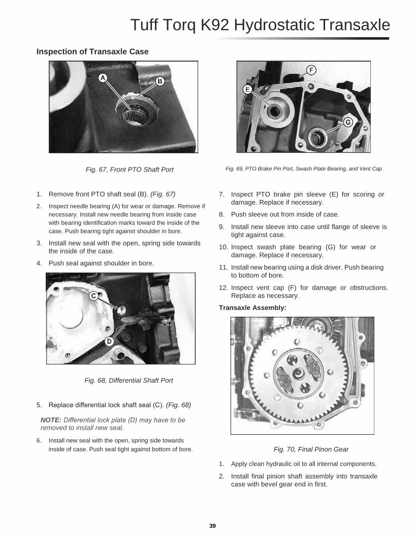
Inspection of Transaxle Case
Fig. 67, Front PTO Shaft Port
1. Remove front PTO shaft seal (B). (Fig. 67) 2. Inspect needle bearing (A) for wear or damage. Remove if
necessary. Install new needle bearing from inside case
with bearing identification marks toward the inside of the
case. Push bearing tight against shoulder in bore. 3. Install new seal with the open, spring side towards
the inside of the case. 4. Push seal against shoulder in bore.
Fig. 69, PTO Brake Pin Port, Swash Plate Bearing, and Vent Cap
7. Inspect PTO brake pin sleeve (E) for scoring or
damage. Replace if necessary. 8. Push sleeve out from inside of case. 9. Install new sleeve into case until flange of sleeve is
tight against case. 10. Inspect swash plate bearing (G) for wear or
damage. Replace if necessary. 11. Install new bearing using a disk driver. Push bearing
to bottom of bore. 12. Inspect vent cap (F) for damage or obstructions.
Replace as necessary. Transaxle Assembly:
Fig. 68, Differential Shaft Port
5. Replace differential lock shaft seal (C). (Fig. 68)
NOTE: Differential lock plate (D) may have to be removed to install new seal.
6. Install new seal with the open, spring side towards
inside of case. Push seal tight against bottom of bore.
Fig. 70, Final Pinon Gear 1. Apply clean hydraulic oil to all internal components. 2. Install final pinion shaft assembly into transaxle
case with bevel gear end in first. 39

IMPORTANT: Avoid damage! Bearing and washer on top of
differential assembly are loose. Do not drop or lose parts. 3. Put fork of differential lock shaft into groove of collar
on differential assembly. Install differential assembly
and differential lock shaft together into transaxle case. 4. Install ball bearing.
Fig. 71, Transaxle Right Cover Assembly
5. Apply a bead of silicon sealant to mating surface
of transaxle case. 6. Carefully lower right transaxle cover assembly (B) onto
case while making sure bearings and shafts fit into
bores properly. Make sure washer on swash plate does
not fall out of position. Secure with sixteen (16) cap
screws (A), and tighten to specification below. (Fig. 71) Transaxle Case Cap Screw Torque Specifications:
• Used Transaxle Case . . . . . . . . . . . . . . 25 N•m (18 lb-ft)
• New Transaxle Case . . . . . . . . . . . . . . . 30 N•m (22 lb-ft)
7. Assemble bearing, washers and snap rings on
input shaft. 8. Install input shaft assembly and large snap ring.
Fig. 72, Without Rear PTO Option, Assembly
Fig. 73, With Rear PTO Option, Assembly
40
9. Install PTO brake shoe (D) and PTO clutch assembly (C).
(See “PTO Brake Removal and Installation” on page 6.)
(Fig. 72) 10. Install PTO idler shaft assembly (E), PTO gear (F) (or rear
PTO gear on rear PTO option units), and snap ring (G). 11. Install PTO drive train. (See “PTO Drive Train (Mid and
Rear PTO) Removal and Installation” on page 11.) 12. Install brakes. (See “Brakes Removal and
Installation” on page 43.)
Tuff Torq K92 Hydrostatic Transaxle
13. Install axle housings. (Fig. 74)
14. Install hydrostatic transmission and pump.
15. Install control arm damper. (See “Control Arm and
Damper Removal and Installation” on page 1)
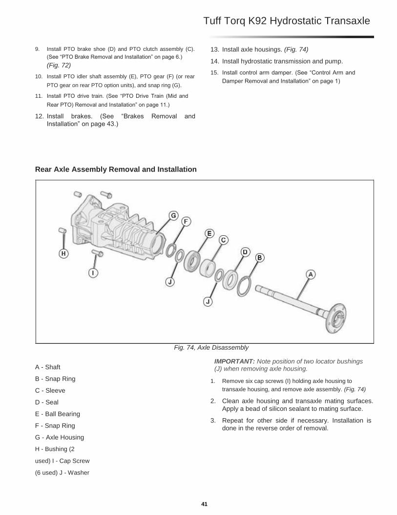
Rear Axle Assembly Removal and Installation
A - Shaft B - Snap Ring C - Sleeve D - Seal E - Ball Bearing F - Snap Ring G - Axle Housing H - Bushing (2
used) I - Cap Screw
(6 used) J - Washer
Fig. 74, Axle Disassembly
IMPORTANT: Note position of two locator bushings (J) when removing axle housing.
1. Remove six cap screws (I) holding axle housing to
transaxle housing, and remove axle assembly. (Fig. 74)
2. Clean axle housing and transaxle mating surfaces.
Apply a bead of silicon sealant to mating surface.
3. Repeat for other side if necessary. Installation is
done in the reverse order of removal.
41
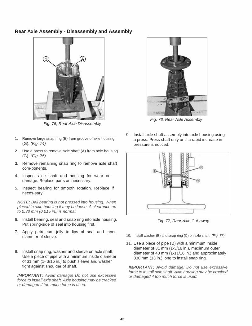
Rear Axle Assembly - Disassembly and Assembly
Fig. 75, Rear Axle Disassembly
1. Remove large snap ring (B) from groove of axle housing (G). (Fig. 74)
2. Use a press to remove axle shaft (A) from axle housing
(G). (Fig. 75) 3. Remove remaining snap ring to remove axle shaft
com-ponents. 4. Inspect axle shaft and housing for wear or
damage. Replace parts as necessary. 5. Inspect bearing for smooth rotation. Replace if
neces-sary.
NOTE: Ball bearing is not pressed into housing. When placed in axle housing it may be loose. A clearance up to 0.38 mm (0.015 in.) is normal.
6. Install bearing, seal and snap ring into axle housing.
Put spring-side of seal into housing first. 7. Apply petroleum jelly to lips of seal and inner
diameter of sleeve.
8. Install snap ring, washer and sleeve on axle shaft.
Use a piece of pipe with a minimum inside diameter
of 31 mm (1- 3/16 in.) to push sleeve and washer
tight against shoulder of shaft.
IMPORTANT: Avoid damage! Do not use excessive force to install axle shaft. Axle housing may be cracked or damaged if too much force is used.
Fig. 76, Rear Axle Assembly
9. Install axle shaft assembly into axle housing using
a press. Press shaft only until a rapid increase in
pressure is noticed.
Fig. 77, Rear Axle Cut-away
10. Install washer (E) and snap ring (C) on axle shaft. (Fig. 77)
11. Use a piece of pipe (D) with a minimum inside
diameter of 31 mm (1-3/16 in.), maximum outer
diameter of 43 mm (1-11/16 in.) and approximately
330 mm (13 in.) long to install snap ring.
IMPORTANT: Avoid damage! Do not use excessive force to install axle shaft. Axle housing may be cracked or damaged if too much force is used.
42

Tuff Torq K92 Hydrostatic Transaxle
Brakes Removal and Installation
A - Snap Ring B - Brake Actuator Plate C - Friction Plate D - Steel Plate E - Steel Ball F - Clevis Pin G - Washer H - Spring Lock Pin I - O-ring J - Interlock Plate K - Cotter Pin L - Washer M - Rod N - Adjustment Nut O - Nut P - Rod
Fig. 78, Brake Disassembly
Q - Cam Lever
R - Brake Cover
S - Cap Screw
1. Inspect components on brake cover (R). Replace as
nec-essary. Apply petroleum jelly to O-ring. (Fig. 78)
2. Inspect plates for wear or spline damage. If groove pat-
tern in friction plates is no longer visible, replace plates.
3. Apply petroleum jelly to balls (E) and install balls
in cover.
4. Install steel plates (D) and friction plates (C)
alternately beginning with a steel plate.
5. Apply a bead of silicon sealant to brake cover
mating surface of transaxle case.
6. Install brake actuator plate (B) and brake cover assembly (R).
Brake Cover Cap Screw Torque Specifications:
Used Transaxle Case . . . . . . . . . . . . . . 25 N•m (18 lb-ft)
New Transaxle Case . . . . . . . . . . . . . . . 30 N•m (22 lb-ft)
43
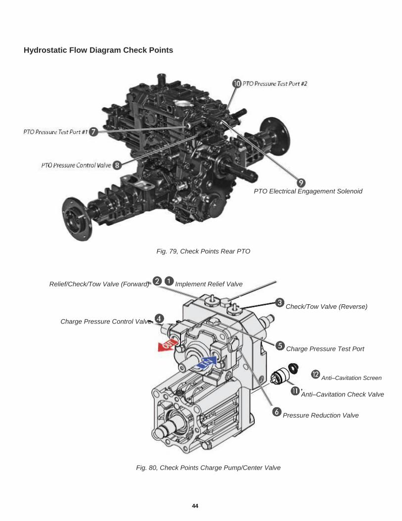
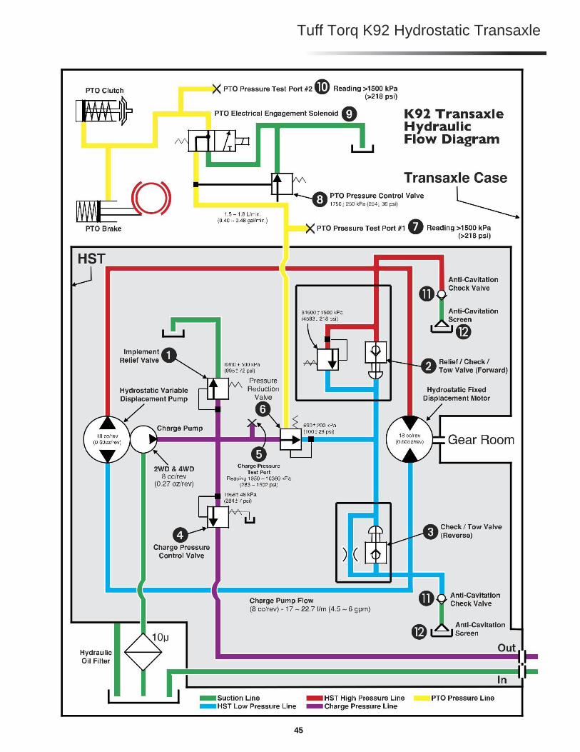
Hydrostatic Flow Diagram Check Points
PTO Electrical Engagement Solenoid
Fig. 79, Check Points Rear PTO
Relief/Check/Tow Valve (Forward) Implement Relief Valve
Check/Tow Valve (Reverse)
Charge Pressure Control Valve
Charge Pressure Test Port
Anti–Cavitation Screen
Anti–Cavitation Check Valve
Pressure Reduction Valve
Fig. 80, Check Points Charge Pump/Center Valve
44
Tuff Torq K92 Hydrostatic Transaxle
45
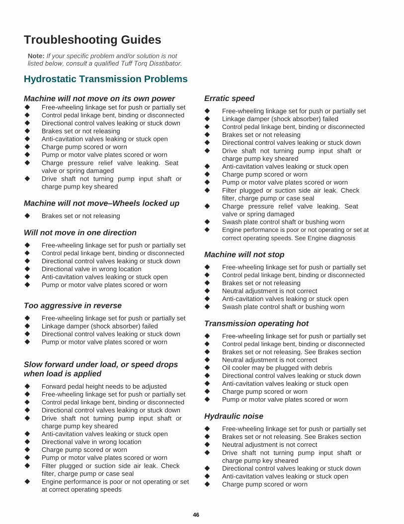
Troubleshooting Guides
Note: If your specific problem and/or solution is not listed below, consult a qualified Tuff Torq Disstibator.
Hydrostatic Transmission Problems
Machine will not move on its own power Free-wheeling linkage set for push or partially set
Control pedal linkage bent, binding or disconnected
Directional control valves leaking or stuck down
Brakes set or not releasing
Anti-cavitation valves leaking or stuck open
Charge pump scored or worn
Pump or motor valve plates scored or worn
Charge pressure relief valve leaking. Seat
valve or spring damaged
Drive shaft not turning pump input shaft or
charge pump key sheared
Machine will not move–Wheels locked up Brakes set or not releasing
Will not move in one direction Free-wheeling linkage set for push or partially set
Control pedal linkage bent, binding or disconnected
Directional control valves leaking or stuck down
Directional valve in wrong location
Anti-cavitation valves leaking or stuck open
Pump or motor valve plates scored or worn
Too aggressive in reverse Free-wheeling linkage set for push or partially set
Linkage damper (shock absorber) failed
Directional control valves leaking or stuck down
Pump or motor valve plates scored or worn
Slow forward under load, or speed drops when load is applied Forward pedal height needs to be adjusted
Free-wheeling linkage set for push or partially set
Control pedal linkage bent, binding or disconnected
Directional control valves leaking or stuck down
Drive shaft not turning pump input shaft or
charge pump key sheared
Anti-cavitation valves leaking or stuck open
Directional valve in wrong location
Charge pump scored or worn
Pump or motor valve plates scored or worn
Filter plugged or suction side air leak. Check
filter, charge pump or case seal
Engine performance is poor or not operating or set
at correct operating speeds
Erratic speed Free-wheeling linkage set for push or partially set
Linkage damper (shock absorber) failed
Control pedal linkage bent, binding or disconnected
Brakes set or not releasing
Directional control valves leaking or stuck down
Drive shaft not turning pump input shaft or
charge pump key sheared
Anti-cavitation valves leaking or stuck open
Charge pump scored or worn
Pump or motor valve plates scored or worn
Filter plugged or suction side air leak. Check
filter, charge pump or case seal
Charge pressure relief valve leaking. Seat
valve or spring damaged
Swash plate control shaft or bushing worn
Engine performance is poor or not operating or set at
correct operating speeds. See Engine diagnosis
Machine will not stop Free-wheeling linkage set for push or partially set
Control pedal linkage bent, binding or disconnected
Brakes set or not releasing
Neutral adjustment is not correct
Anti-cavitation valves leaking or stuck open
Swash plate control shaft or bushing worn
Transmission operating hot Free-wheeling linkage set for push or partially set
Control pedal linkage bent, binding or disconnected
Brakes set or not releasing. See Brakes section
Neutral adjustment is not correct
Oil cooler may be plugged with debris
Directional control valves leaking or stuck down
Anti-cavitation valves leaking or stuck open
Charge pump scored or worn
Pump or motor valve plates scored or worn
Hydraulic noise Free-wheeling linkage set for push or partially set
Brakes set or not releasing. See Brakes section
Neutral adjustment is not correct
Drive shaft not turning pump input shaft or
charge pump key sheared
Directional control valves leaking or stuck down
Anti-cavitation valves leaking or stuck open
Charge pump scored or worn
46
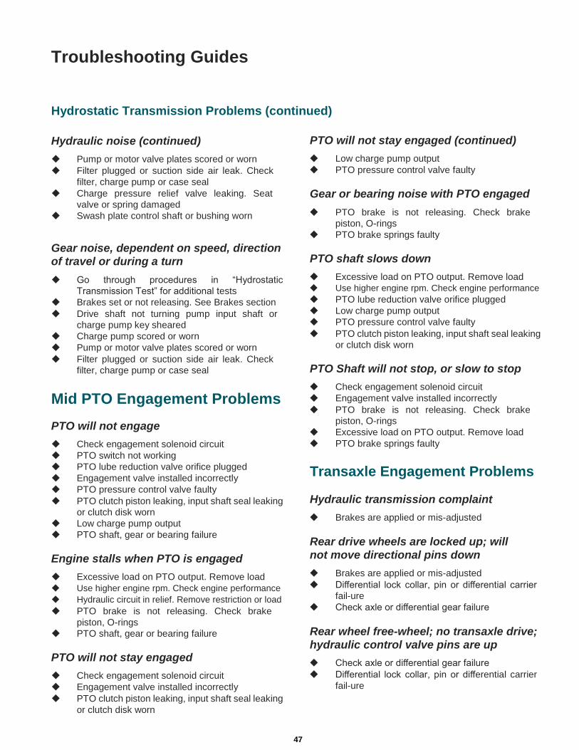
Troubleshooting Guides
Hydrostatic Transmission Problems (continued)
Hydraulic noise (continued) Pump or motor valve plates scored or worn
Filter plugged or suction side air leak. Check
filter, charge pump or case seal
Charge pressure relief valve leaking. Seat
valve or spring damaged
Swash plate control shaft or bushing worn
PTO will not stay engaged (continued) Low charge pump output
PTO pressure control valve faulty
Gear or bearing noise with PTO engaged PTO brake is not releasing. Check brake
piston, O-rings
PTO brake springs faulty
Gear noise, dependent on speed, direction of travel or during a turn Go through procedures in “Hydrostatic
Transmission Test” for additional tests
Brakes set or not releasing. See Brakes section
Drive shaft not turning pump input shaft or
charge pump key sheared
Charge pump scored or worn
Pump or motor valve plates scored or worn
Filter plugged or suction side air leak. Check
filter, charge pump or case seal
Mid PTO Engagement Problems
PTO will not engage Check engagement solenoid circuit
PTO switch not working
PTO lube reduction valve orifice plugged
Engagement valve installed incorrectly
PTO pressure control valve faulty
PTO clutch piston leaking, input shaft seal leaking
or clutch disk worn
Low charge pump output
PTO shaft, gear or bearing failure
Engine stalls when PTO is engaged Excessive load on PTO output. Remove load
Use higher engine rpm. Check engine performance
Hydraulic circuit in relief. Remove restriction or load
PTO brake is not releasing. Check brake
piston, O-rings
PTO shaft, gear or bearing failure
PTO will not stay engaged Check engagement solenoid circuit
Engagement valve installed incorrectly
PTO clutch piston leaking, input shaft seal leaking
or clutch disk worn
PTO shaft slows down Excessive load on PTO output. Remove load
Use higher engine rpm. Check engine performance
PTO lube reduction valve orifice plugged
Low charge pump output
PTO pressure control valve faulty
PTO clutch piston leaking, input shaft seal leaking
or clutch disk worn
PTO Shaft will not stop, or slow to stop Check engagement solenoid circuit
Engagement valve installed incorrectly
PTO brake is not releasing. Check brake
piston, O-rings
Excessive load on PTO output. Remove load
PTO brake springs faulty
Transaxle Engagement Problems
Hydraulic transmission complaint Brakes are applied or mis-adjusted
Rear drive wheels are locked up; will not move directional pins down Brakes are applied or mis-adjusted
Differential lock collar, pin or differential carrier
fail-ure
Check axle or differential gear failure
Rear wheel free-wheel; no transaxle drive; hydraulic control valve pins are up Check axle or differential gear failure
Differential lock collar, pin or differential carrier
fail-ure
47
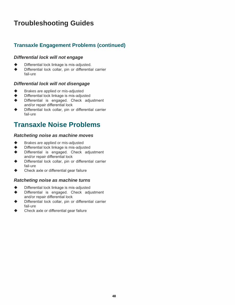
Troubleshooting Guides
Transaxle Engagement Problems (continued)
Differential lock will not engage Differential lock linkage is mis-adjusted.
Differential lock collar, pin or differential carrier
fail-ure
Differential lock will not disengage Brakes are applied or mis-adjusted
Differential lock linkage is mis-adjusted
Differential is engaged. Check adjustment
and/or repair differential lock
Differential lock collar, pin or differential carrier
fail-ure
Transaxle Noise Problems
Ratcheting noise as machine moves Brakes are applied or mis-adjusted
Differential lock linkage is mis-adjusted
Differential is engaged. Check adjustment
and/or repair differential lock
Differential lock collar, pin or differential carrier
fail-ure
Check axle or differential gear failure
Ratcheting noise as machine turns Differential lock linkage is mis-adjusted
Differential is engaged. Check adjustment
and/or repair differential lock
Differential lock collar, pin or differential carrier
fail-ure
Check axle or differential gear failure 48


