August 27, 2015 Melanie A. Bachman Connecticut Siting Council 10 Franklin Square New Britain, CT 06051 RE: T-Mobile - Exempt Modification - Crown Site BU: 806368 T-Mobile Site ID: CT11248A Located at: 374 Three Mile Road, Glastonbury, CT 06033 Dear Ms. Bachman: This letter and exhibits are submitted on behalf of T-Mobile. T-Mobile is making modifications to certain existing sites in its Connecticut system in order to implement their 700MHz technology. Please accept this letter and exhibits as notification, pursuant to § 16-50j-73 of the Regulations of Connecticut State Agencies (“R.C.S.A.”), of construction that constitutes an exempt modification pursuant to R.C.S.A. § 16-50j-72(b)(2). In compliance with R.C.S.A. § 16-50j-73, a copy of this letter is being sent to the Town Manager, Richard J. Johnson, and Mr. John R. Flanagan, Property Owner. T-Mobile plans to modify the existing wireless communications facility owned by Crown Castle and located at 374 Three Mile Road, Glastonbury, CT. Attached are a compound plan and elevation depicting the planned changes (Exhibit-1), and documentation of the structural sufficiency of the structure to accommodate the revised antenna configuration (Exhibit-2). Also included is a power density table report reflecting the modification to T-Mobile’s operations at the site (Exhibit-3). The changes to the facility do not constitute a modification as defined in Connecticut General Statutes (“C.G.S.”) § 16-50i(d) because the general physical characteristics of the facility will not be significantly changed. Rather, the planned changes to the facility fall squarely within those activities explicitly provided for in the R.C.S.A. § 16-50j-72(b)(2). 1. The proposed modifications will not result in an increase in the height of the existing tower. T-Mobile’s additional antennas will be located at the same elevation on the existing tower. 2. There will be no proposed modifications to the ground and no extension of boundaries. 3. The proposed modifications will not increase noise levels at the facility by six decibels or more.
Transcript
August 27, 2015
Melanie A. Bachman
Connecticut Siting Council
10 Franklin Square
New Britain, CT 06051
RE: T-Mobile - Exempt Modification - Crown Site BU: 806368
T-Mobile Site ID: CT11248A
Located at: 374 Three Mile Road, Glastonbury, CT 06033
Dear Ms. Bachman:
This letter and exhibits are submitted on behalf of T-Mobile. T-Mobile is making modifications
to certain existing sites in its Connecticut system in order to implement their 700MHz technology.
Please accept this letter and exhibits as notification, pursuant to § 16-50j-73 of the Regulations of
Connecticut State Agencies (“R.C.S.A.”), of construction that constitutes an exempt modification
pursuant to R.C.S.A. § 16-50j-72(b)(2). In compliance with R.C.S.A. § 16-50j-73, a copy of this letter
is being sent to the Town Manager, Richard J. Johnson, and Mr. John R. Flanagan, Property Owner.
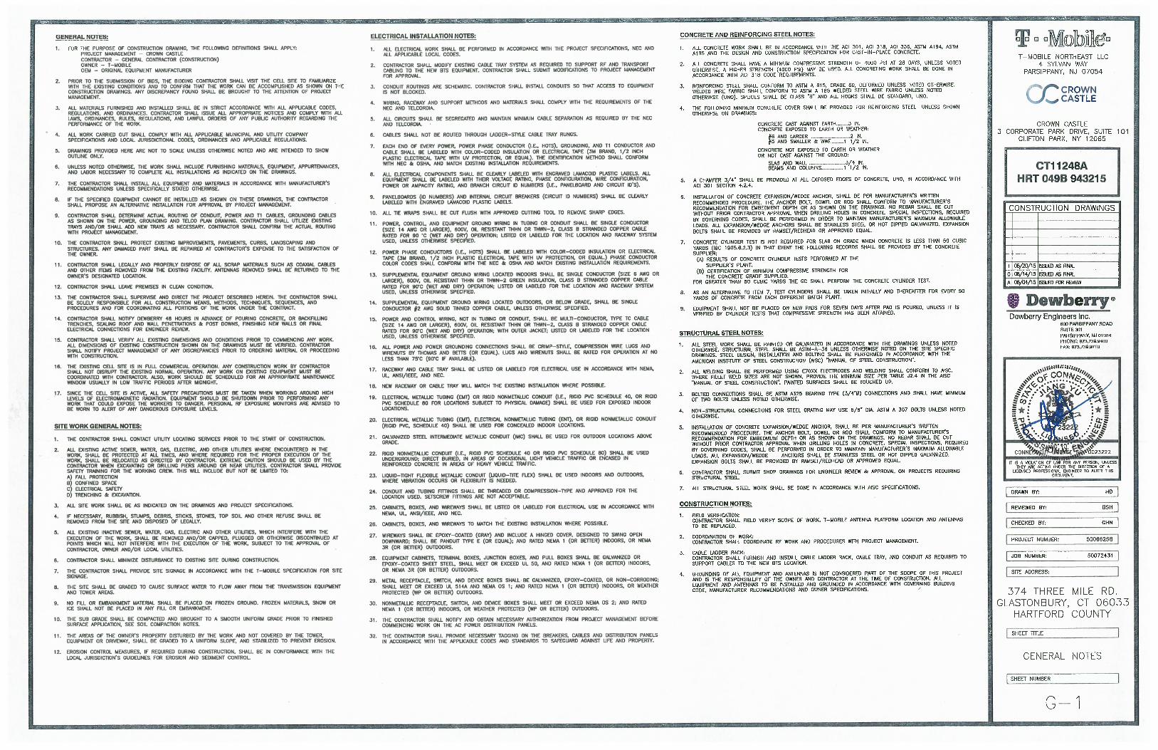
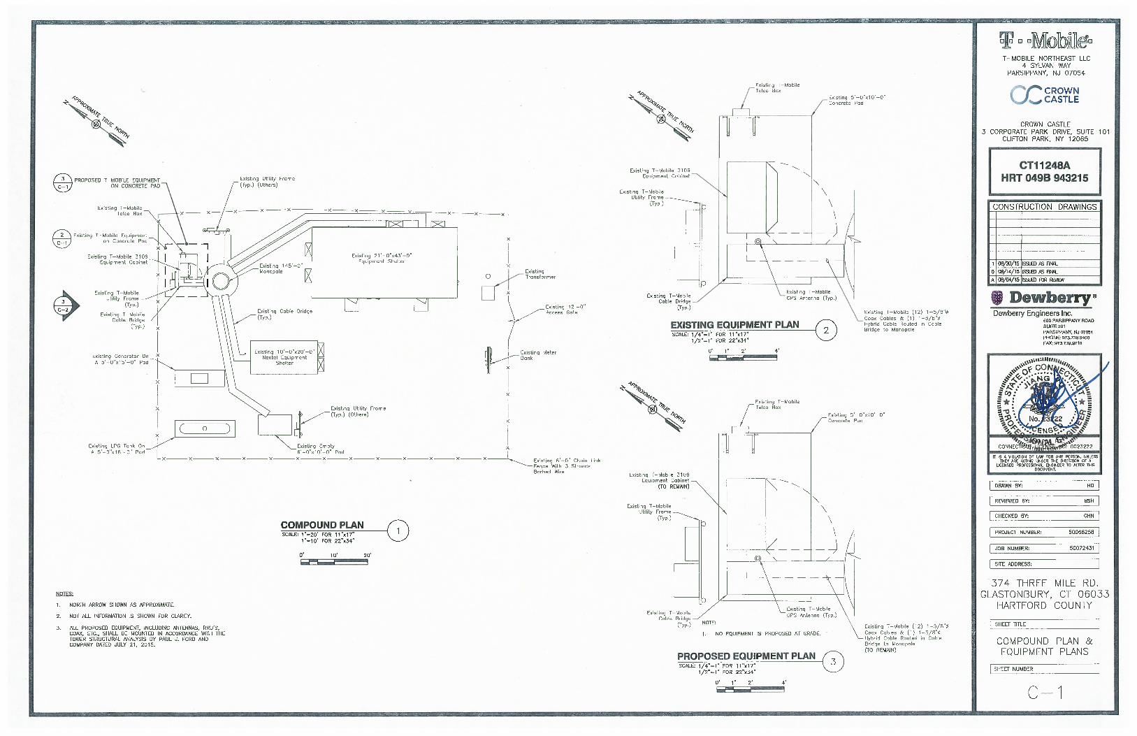
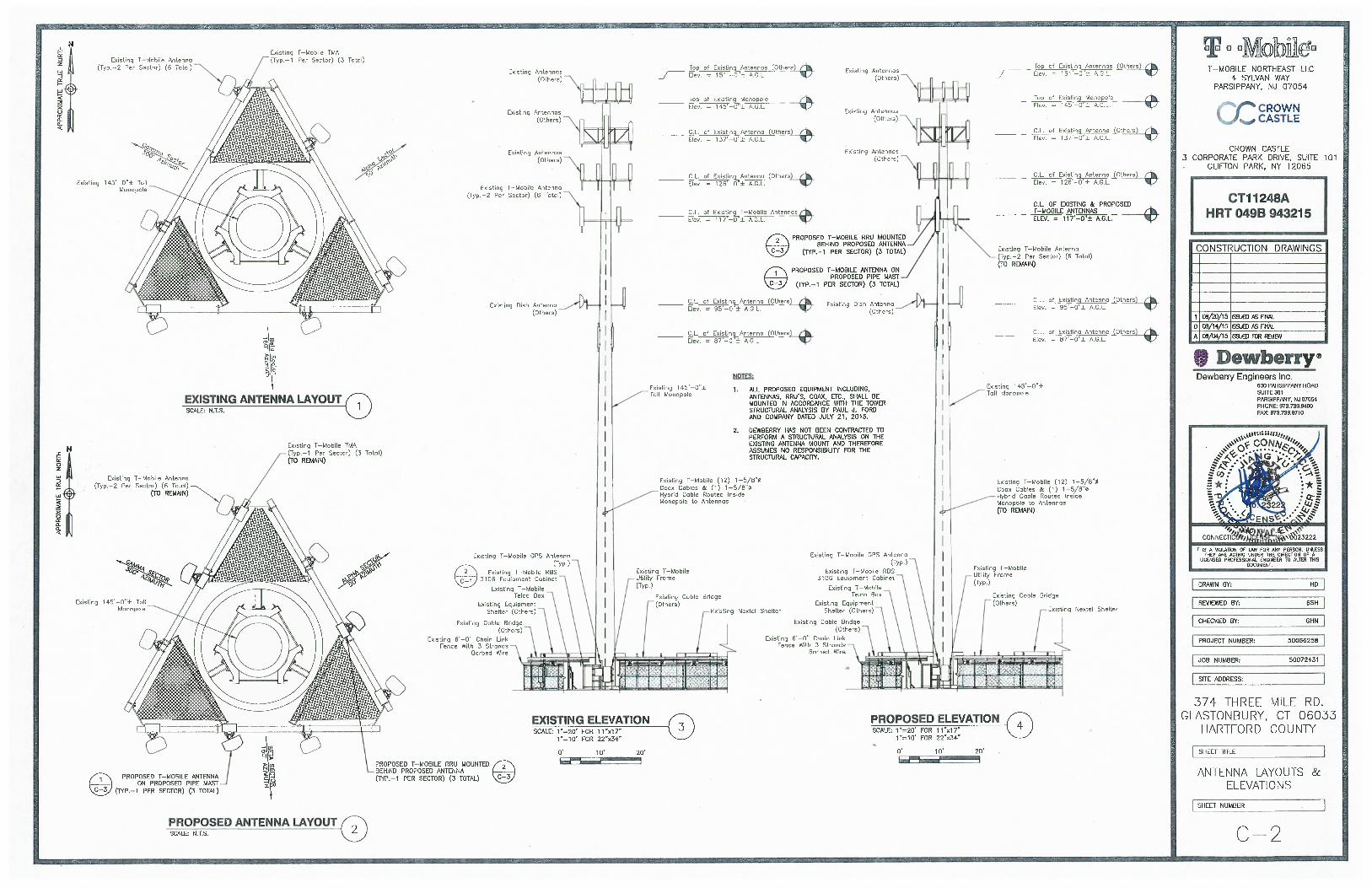
T-Mobile plans to modify the existing wireless communications facility owned by Crown Castle
and located at 374 Three Mile Road, Glastonbury, CT. Attached are a compound plan and elevation
depicting the planned changes (Exhibit-1), and documentation of the structural sufficiency of the
structure to accommodate the revised antenna configuration (Exhibit-2). Also included is a power
density table report reflecting the modification to T-Mobile’s operations at the site (Exhibit-3).
The changes to the facility do not constitute a modification as defined in Connecticut General
Statutes (“C.G.S.”) § 16-50i(d) because the general physical characteristics of the facility will not be
significantly changed. Rather, the planned changes to the facility fall squarely within those activities
explicitly provided for in the R.C.S.A. § 16-50j-72(b)(2).
1. The proposed modifications will not result in an increase in the height of the existing tower.
T-Mobile’s additional antennas will be located at the same elevation on the existing tower.
2. There will be no proposed modifications to the ground and no extension of boundaries.
3. The proposed modifications will not increase noise levels at the facility by six decibels or
more.
Melanie A. Bachman
August 27, 2015
Page 2
4. A Structural Modification Report confirming that the tower and foundation can support T-
Mobile’s proposed modifications is included as Exhibit-2.
5. The operation of the additional antennas will not increase radio frequency (RF) emissions at
the facility to a level at or above the Federal Communications Commission (FCC) adopted
safety standard. A cumulative General Power Density table report for T-Mobile’s modified
facility is included as Exhibit-3.
For the foregoing reasons, T-Mobile respectfully submits the proposed modifications to the
above-reference telecommunications facility constitutes an exempt modification under R.C.S.A. § 16-
50j-72(b)(2). Please send approval/rejection letter to Attn: Kimberly Myl.
Sincerely,
Kimberly Myl
Real Estate Specialist
Enclosures
Tab 1: Exhibit-1: Compound plan and elevation depicting the planned changes
Tab 2: Exhibit-2: Structural Modification Report
Tab 3: Exhibit-3: General Power Density Table Report (RF Emissions Analysis Report)
cc: Mr. Richard J. Johnson, Town Manager
Town of Glastonbury
2155 Main Street
Glastonbury, CT 06033
Mr. John R. Flanagan
366 Three Mile Road
Glastonbury, CT 06033
tnxTower Report - version 6.1.4.1
Date: July 21, 2015
Sean Dempsey Paul J Ford and CompanyCrown Castle 250 E. Broad Street Suite 6003530 Toringdon Way Columbus, OH 43215Charlotte, NC 28277 614.221.6679
Subject: Structural Analysis Report
Carrier Designation: T-Mobile Co-LocateCarrier Site Number: CT11248ACarrier Site Name: Glastonbury
Crown Castle Designation: Crown Castle BU Number: 806368Crown Castle Site Name: HRT 049B 943215Crown Castle JDE Job Number: 340886Crown Castle Work Order Number: 1092755Crown Castle Application Number: 303529 Rev. 0
Engineering Firm Designation: Paul J Ford and Company Project Number: 37515-2141.002.7805
Site Data: 374 Three Mile Rd., GLASTONBURY, Hartford County, CTLatitude 41° 41' 36.93'', Longitude -72° 32' 50.11''145 Foot - Monopole Tower
Dear Sean Dempsey,
Paul J Ford and Company is pleased to submit this “Structural Analysis Report” to determine the structural
integrity of the above mentioned tower. This analysis has been performed in accordance with the Crown CastleStructural ‘Statement of Work’ and the terms of Crown Castle Purchase Order Number 808496, in accordancewith application 303529, revision 0.
The purpose of the analysis is to determine acceptability of the tower stress level. Based on our analysis wehave determined the tower stress level for the structure and foundation, under the following load case, to be:
LC7: Existing + Reserved + Proposed Equipment Sufficient CapacityNote: See Table I and Table II for the proposed and existing/reserved loading, respectively.
This analysis has been performed in accordance with the TIA/EIA-222-F standard and 2005 CT State BuildingCode with 2009 amendment based upon a wind speed of 80 mph fastest mile.
We at Paul J Ford and Company appreciate the opportunity of providing our continuing professional services toyou and Crown Castle. If you have any questions or need further assistance on this or any other projectsplease give us a call.
Respectfully submitted by:
Jared Smith, E.I.Structural Designer
July 21, 2015145 Ft Monopole Tower Structural Analysis CCI BU No 806368Project Number 37515-2141.002.7805, Application 303529, Revision 0 Page 2
tnxTower Report - version 6.1.4.1
TABLE OF CONTENTS
1) INTRODUCTION
2) ANALYSIS CRITERIATable 1 - Proposed Antenna and Cable InformationTable 2 - Existing and Reserved Antenna and Cable Information
July 21, 2015145 Ft Monopole Tower Structural Analysis CCI BU No 806368Project Number 37515-2141.002.7805, Application 303529, Revision 0 Page 3
tnxTower Report - version 6.1.4.1
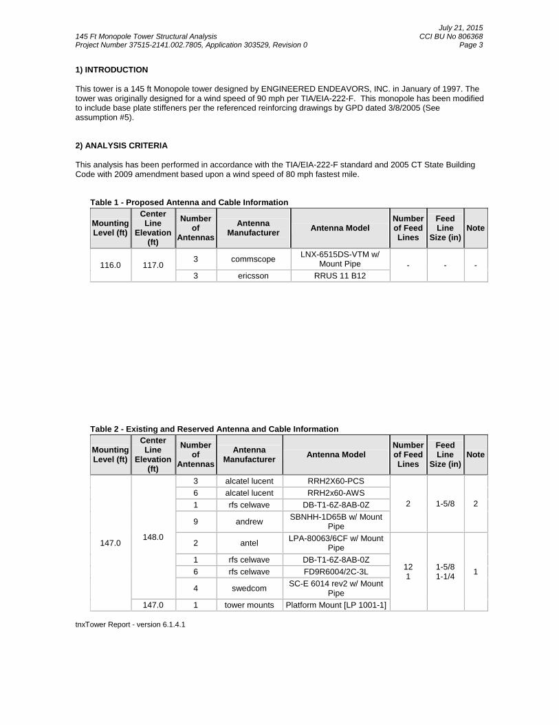
1) INTRODUCTION
This tower is a 145 ft Monopole tower designed by ENGINEERED ENDEAVORS, INC. in January of 1997. Thetower was originally designed for a wind speed of 90 mph per TIA/EIA-222-F. This monopole has been modifiedto include base plate stiffeners per the referenced reinforcing drawings by GPD dated 3/8/2005 (Seeassumption #5).
2) ANALYSIS CRITERIA
This analysis has been performed in accordance with the TIA/EIA-222-F standard and 2005 CT State BuildingCode with 2009 amendment based upon a wind speed of 80 mph fastest mile.
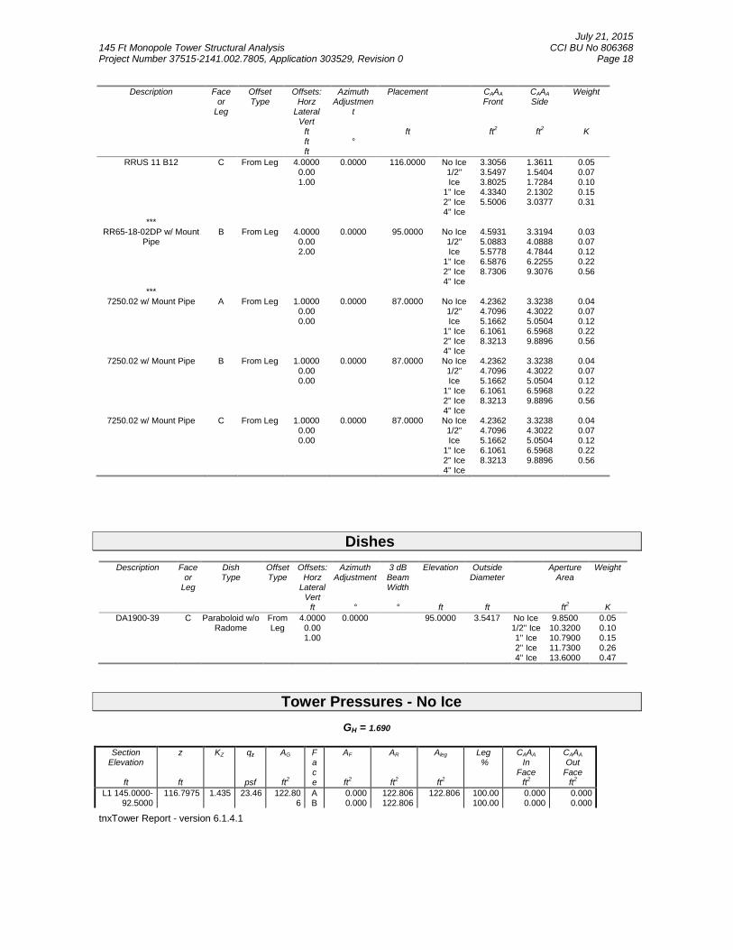
Table 1 - Proposed Antenna and Cable Information
MountingLevel (ft)
CenterLine
Elevation(ft)
Numberof
Antennas
AntennaManufacturer
Antenna ModelNumberof FeedLines
FeedLine
Size (in)Note
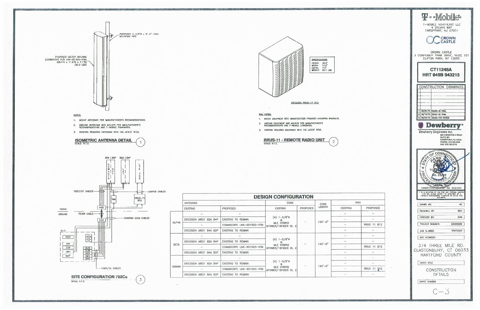
116.0 117.03 commscope
LNX-6515DS-VTM w/Mount Pipe - - -
3 ericsson RRUS 11 B12
Table 2 - Existing and Reserved Antenna and Cable Information
MountingLevel (ft)
CenterLine
Elevation(ft)
Numberof
Antennas
AntennaManufacturer
Antenna ModelNumberof FeedLines
FeedLine
Size (in)Note
147.0148.0
3 alcatel lucent RRH2X60-PCS
2 1-5/8 2
6 alcatel lucent RRH2x60-AWS
1 rfs celwave DB-T1-6Z-8AB-0Z
9 andrewSBNHH-1D65B w/ Mount
Pipe
2 antelLPA-80063/6CF w/ Mount
Pipe
121
1-5/81-1/4
1
1 rfs celwave DB-T1-6Z-8AB-0Z
6 rfs celwave FD9R6004/2C-3L
4 swedcomSC-E 6014 rev2 w/ Mount
Pipe
147.0 1 tower mounts Platform Mount [LP 1001-1]
July 21, 2015145 Ft Monopole Tower Structural Analysis CCI BU No 806368Project Number 37515-2141.002.7805, Application 303529, Revision 0 Page 4
tnxTower Report - version 6.1.4.1
MountingLevel (ft)
CenterLine
Elevation(ft)
Numberof
Antennas
AntennaManufacturer
Antenna ModelNumberof FeedLines
FeedLine
Size (in)Note
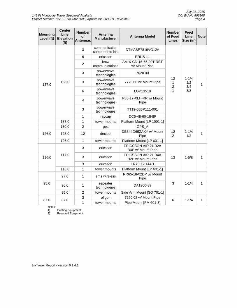
137.0138.0
3communicationcomponents inc.
DTMABP7819VG12A
12121
1-1/41/23/43/8
1
6 ericsson RRUS-11
2kmw
communicationsAM-X-CD-16-65-00T-RET
w/ Mount Pipe
3powerwave
technologies7020.00
3powerwave
technologies7770.00 w/ Mount Pipe
6powerwave
technologiesLGP13519
4powerwave
technologiesP65-17-XLH-RR w/ Mount
Pipe
3powerwave
technologiesTT19-08BP111-001
1 raycap DC6-48-60-18-8F
137.0 1 tower mounts Platform Mount [LP 1001-1]
126.0
130.0 2 gps GPS_A
122
1-1/41/2
1128.0 12 decibelDB844G65ZAXY w/ Mount
Pipe
126.0 1 tower mounts Platform Mount [LP 601-1]
116.0117.0
3 ericssonERICSSON AIR 21 B2A
B4P w/ Mount Pipe
13 1-5/8 13 ericssonERICSSON AIR 21 B4A
B2P w/ Mount Pipe
3 ericsson KRY 112 144/1
116.0 1 tower mounts Platform Mount [LP 601-1]
95.0
97.0 1 ems wirelessRR65-18-02DP w/ Mount
Pipe
3 1-1/4 196.0 1
repeatertechnologies
DA1900-39
95.0 2 tower mounts Side Arm Mount [SO 701-1]
87.0 87.03 allgon 7250.02 w/ Mount Pipe
6 1-1/4 11 tower mounts Pipe Mount [PM 601-3]
Notes:1) Existing Equipment2) Reserved Equipment
July 21, 2015145 Ft Monopole Tower Structural Analysis CCI BU No 806368Project Number 37515-2141.002.7805, Application 303529, Revision 0 Page 5
tnxTower Report - version 6.1.4.1
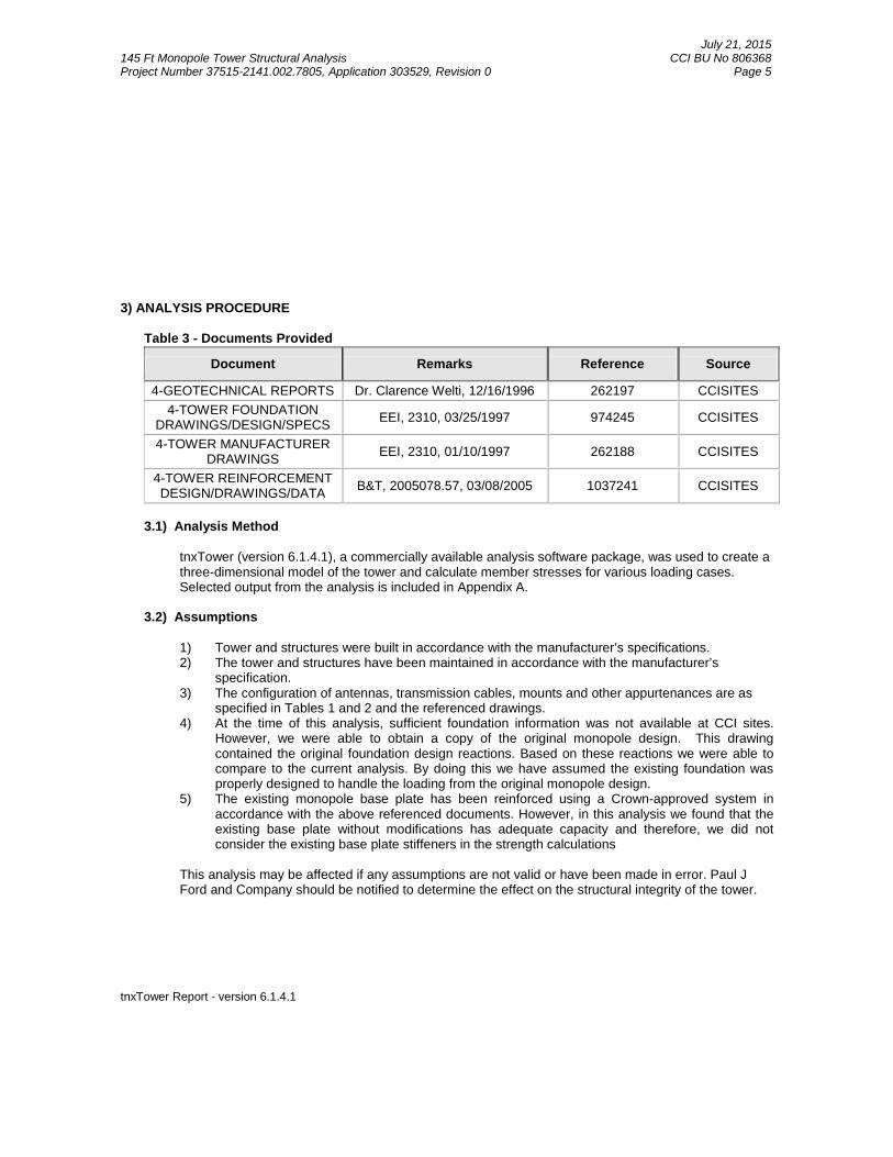
3) ANALYSIS PROCEDURE
Table 3 - Documents Provided
Document Remarks Reference Source
4-GEOTECHNICAL REPORTS Dr. Clarence Welti, 12/16/1996 262197 CCISITES
4-TOWER FOUNDATIONDRAWINGS/DESIGN/SPECS
EEI, 2310, 03/25/1997 974245 CCISITES
4-TOWER MANUFACTURERDRAWINGS
EEI, 2310, 01/10/1997 262188 CCISITES
4-TOWER REINFORCEMENTDESIGN/DRAWINGS/DATA
B&T, 2005078.57, 03/08/2005 1037241 CCISITES
3.1) Analysis Method
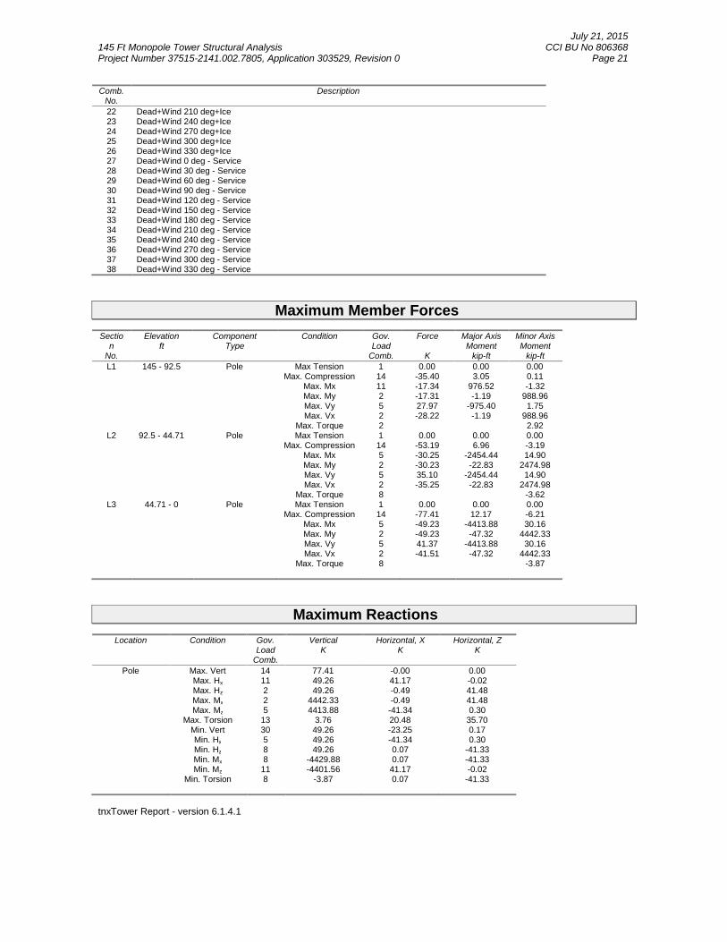
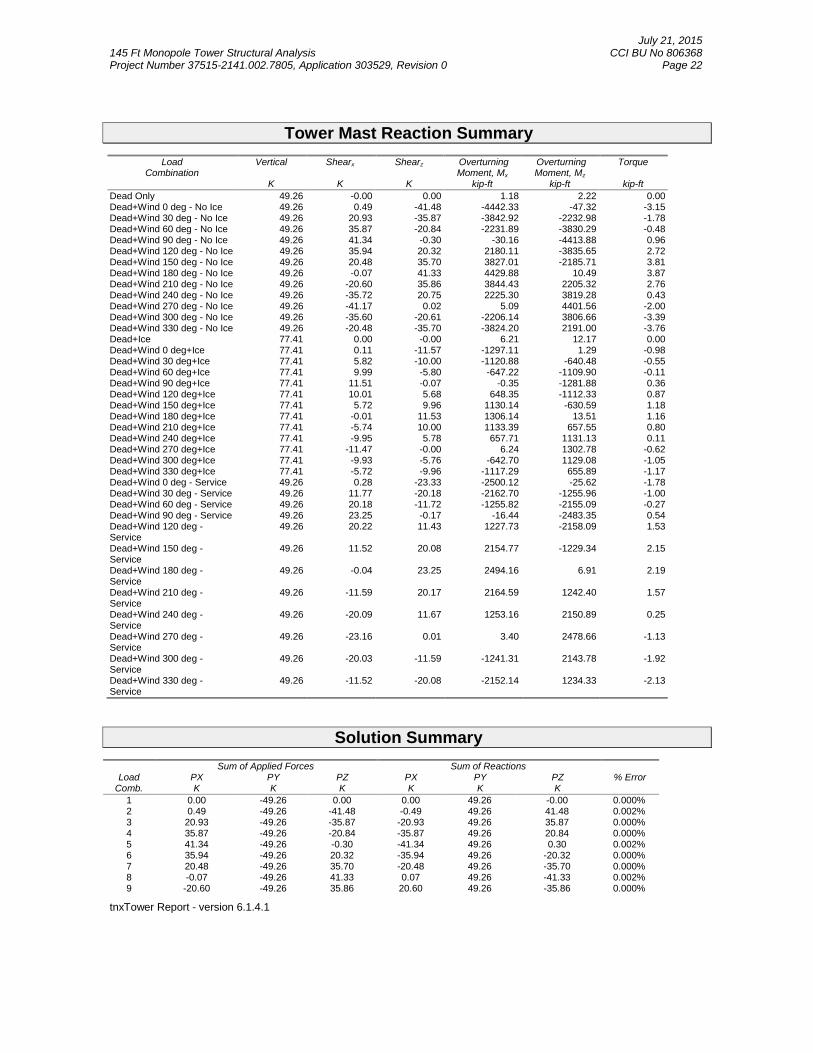
tnxTower (version 6.1.4.1), a commercially available analysis software package, was used to create athree-dimensional model of the tower and calculate member stresses for various loading cases.Selected output from the analysis is included in Appendix A.
3.2) Assumptions
1) Tower and structures were built in accordance with the manufacturer’s specifications.2) The tower and structures have been maintained in accordance with the manufacturer’s
specification.3) The configuration of antennas, transmission cables, mounts and other appurtenances are as
specified in Tables 1 and 2 and the referenced drawings.4) At the time of this analysis, sufficient foundation information was not available at CCI sites.
However, we were able to obtain a copy of the original monopole design. This drawingcontained the original foundation design reactions. Based on these reactions we were able tocompare to the current analysis. By doing this we have assumed the existing foundation wasproperly designed to handle the loading from the original monopole design.
5) The existing monopole base plate has been reinforced using a Crown-approved system inaccordance with the above referenced documents. However, in this analysis we found that theexisting base plate without modifications has adequate capacity and therefore, we did notconsider the existing base plate stiffeners in the strength calculations
This analysis may be affected if any assumptions are not valid or have been made in error. Paul JFord and Company should be notified to determine the effect on the structural integrity of the tower.
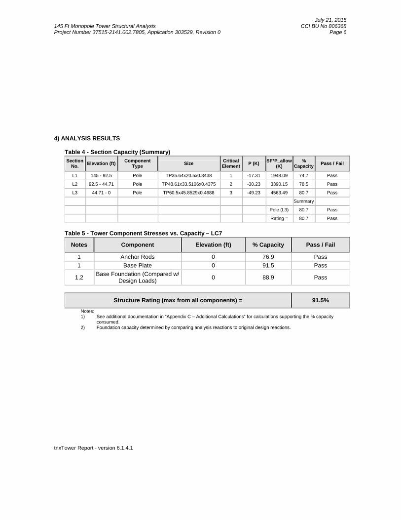
July 21, 2015145 Ft Monopole Tower Structural Analysis CCI BU No 806368Project Number 37515-2141.002.7805, Application 303529, Revision 0 Page 6
Structure Rating (max from all components) = 91.5%
Notes:1) See additional documentation in “Appendix C – Additional Calculations” for calculations supporting the % capacity
consumed.2) Foundation capacity determined by comparing analysis reactions to original design reactions.
July 21, 2015145 Ft Monopole Tower Structural Analysis CCI BU No 806368Project Number 37515-2141.002.7805, Application 303529, Revision 0 Page 7
tnxTower Report - version 6.1.4.1
APPENDIX A
TNXTOWER OUTPUT
July 21, 2015145 Ft Monopole Tower Structural Analysis CCI BU No 806368Project Number 37515-2141.002.7805, Application 303529, Revision 0 Page 8
tnxTower Report - version 6.1.4.1
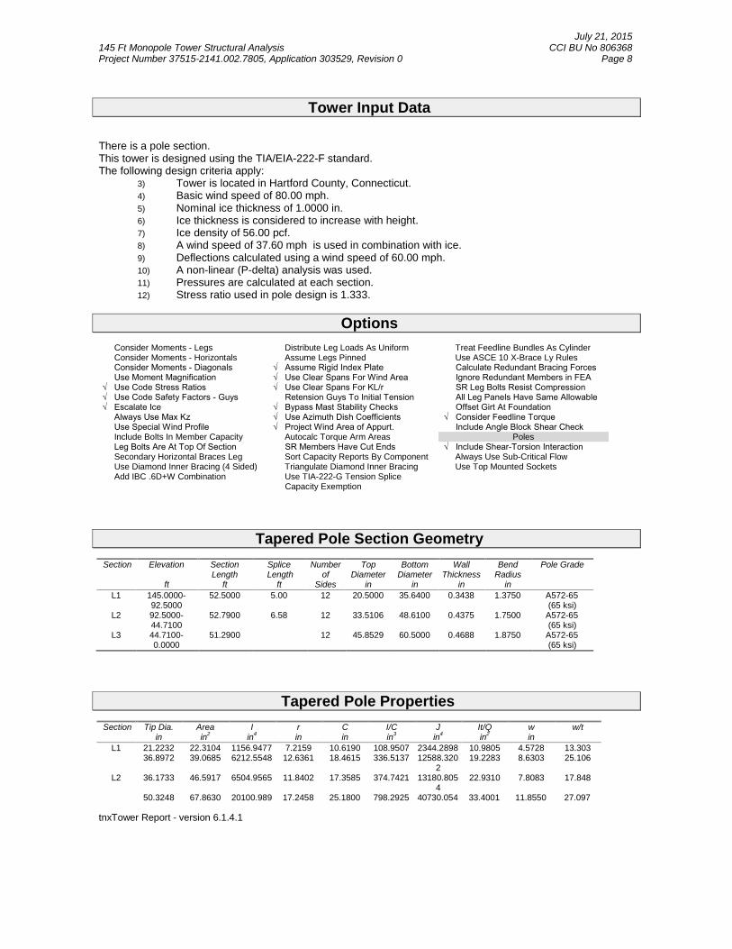
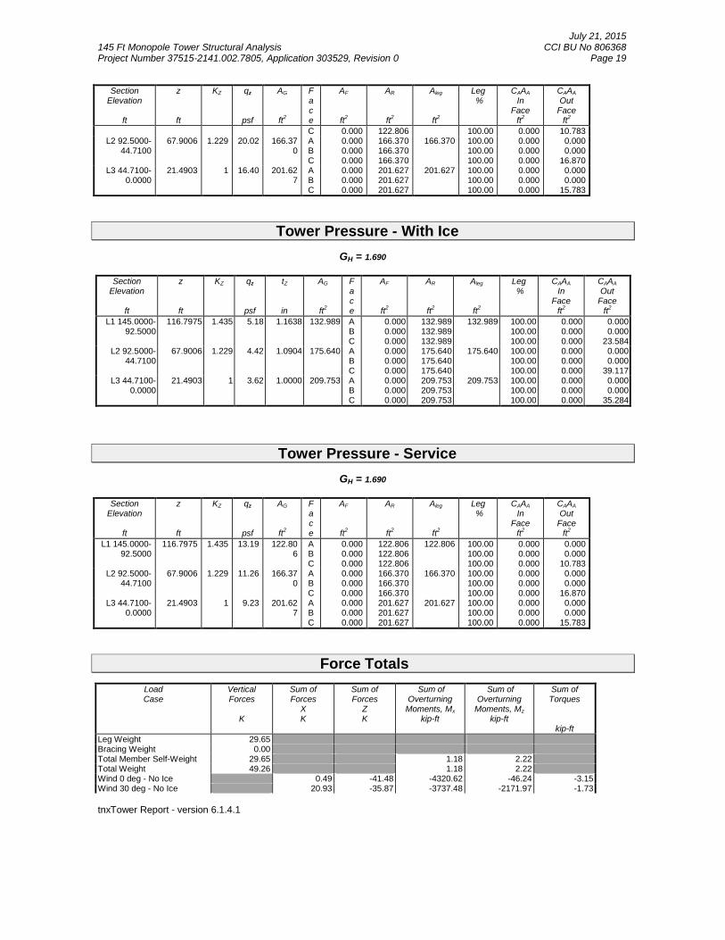
Tower Input Data
There is a pole section.This tower is designed using the TIA/EIA-222-F standard.The following design criteria apply:
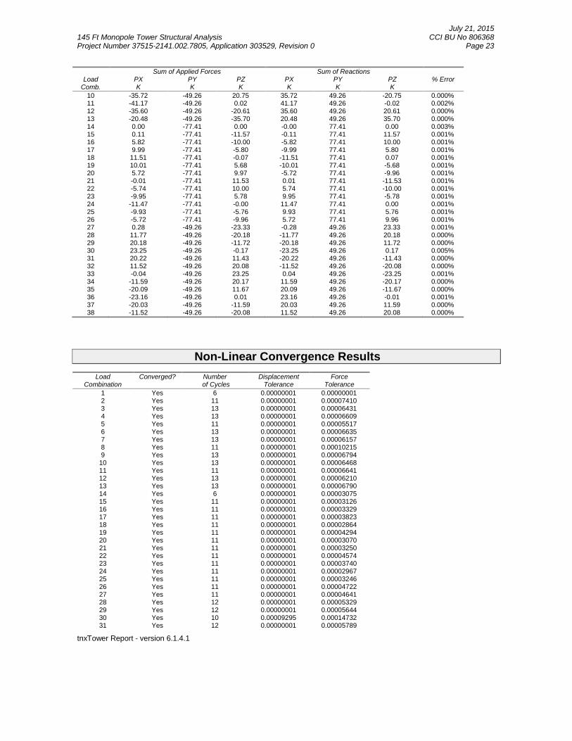
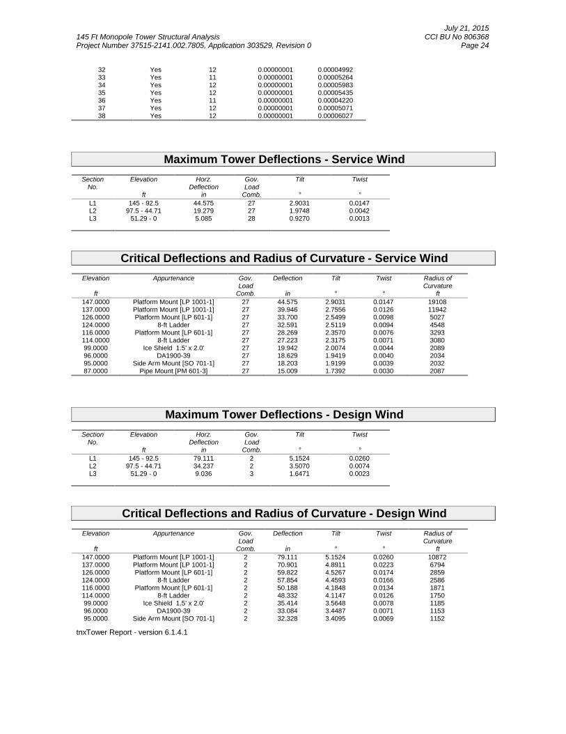
3) Tower is located in Hartford County, Connecticut.4) Basic wind speed of 80.00 mph.5) Nominal ice thickness of 1.0000 in.6) Ice thickness is considered to increase with height.7) Ice density of 56.00 pcf.8) A wind speed of 37.60 mph is used in combination with ice.9) Deflections calculated using a wind speed of 60.00 mph.10) A non-linear (P-delta) analysis was used.11) Pressures are calculated at each section.12) Stress ratio used in pole design is 1.333.
Options
Consider Moments - Legs Distribute Leg Loads As Uniform Treat Feedline Bundles As CylinderConsider Moments - Horizontals Assume Legs Pinned Use ASCE 10 X-Brace Ly Rules
Consider Moments - Diagonals √ Assume Rigid Index Plate Calculate Redundant Bracing Forces Use Moment Magnification √ Use Clear Spans For Wind Area Ignore Redundant Members in FEA √ Use Code Stress Ratios √ Use Clear Spans For KL/r SR Leg Bolts Resist Compression √ Use Code Safety Factors - Guys Retension Guys To Initial Tension All Leg Panels Have Same Allowable √ Escalate Ice √ Bypass Mast Stability Checks Offset Girt At Foundation Always Use Max Kz √ Use Azimuth Dish Coefficients √ Consider Feedline Torque Use Special Wind Profile √ Project Wind Area of Appurt. Include Angle Block Shear Check
Include Bolts In Member Capacity Autocalc Torque Arm Areas Poles Leg Bolts Are At Top Of Section SR Members Have Cut Ends √ Include Shear-Torsion Interaction
Secondary Horizontal Braces Leg Sort Capacity Reports By Component Always Use Sub-Critical FlowUse Diamond Inner Bracing (4 Sided) Triangulate Diamond Inner Bracing Use Top Mounted SocketsAdd IBC .6D+W Combination Use TIA-222-G Tension Splice
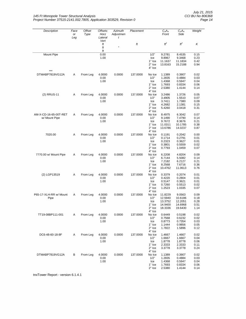
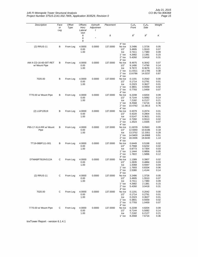
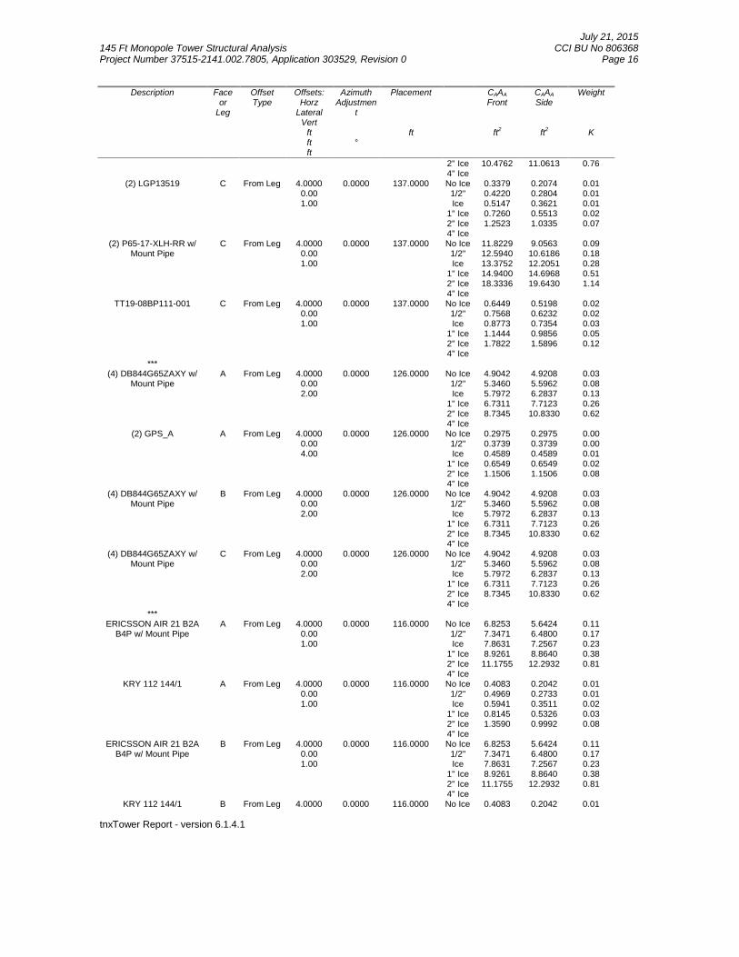
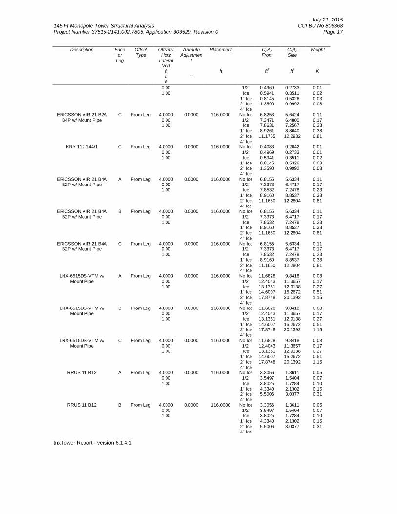
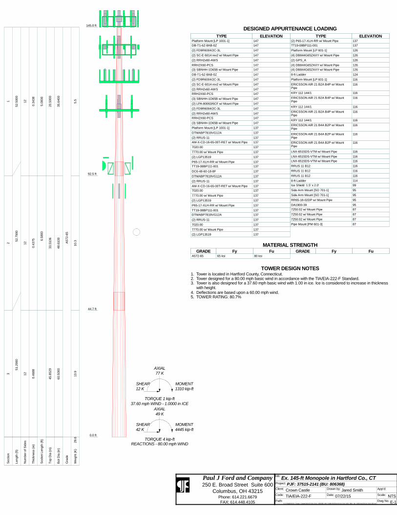
Platform Mount [LP 1001-1] 147DB-T1-6Z-8AB-0Z 147(2) FD9R6004/2C-3L 147(2) SC-E 6014 rev2 w/ Mount Pipe 147(2) RRH2x60-AWS 147RRH2X60-PCS 147(3) SBNHH-1D65B w/ Mount Pipe 147DB-T1-6Z-8AB-0Z 147(2) FD9R6004/2C-3L 147(2) SC-E 6014 rev2 w/ Mount Pipe 147(2) RRH2x60-AWS 147RRH2X60-PCS 147(3) SBNHH-1D65B w/ Mount Pipe 147(2) LPA-80063/6CF w/ Mount Pipe 147(2) FD9R6004/2C-3L 147(2) RRH2x60-AWS 147RRH2X60-PCS 147(3) SBNHH-1D65B w/ Mount Pipe 147Platform Mount [LP 1001-1] 137DTMABP7819VG12A 137(2) RRUS-11 137AM-X-CD-16-65-00T-RET w/ Mount Pipe 1377020.00 1377770.00 w/ Mount Pipe 137(2) LGP13519 137P65-17-XLH-RR w/ Mount Pipe 137TT19-08BP111-001 137DC6-48-60-18-8F 137DTMABP7819VG12A 137(2) RRUS-11 137AM-X-CD-16-65-00T-RET w/ Mount Pipe 1377020.00 1377770.00 w/ Mount Pipe 137(2) LGP13519 137P65-17-XLH-RR w/ Mount Pipe 137TT19-08BP111-001 137DTMABP7819VG12A 137(2) RRUS-11 1377020.00 1377770.00 w/ Mount Pipe 137(2) LGP13519 137(2) P65-17-XLH-RR w/ Mount Pipe 137TT19-08BP111-001 137Platform Mount [LP 601-1] 126(4) DB844G65ZAXY w/ Mount Pipe 126(2) GPS_A 126(4) DB844G65ZAXY w/ Mount Pipe 126(4) DB844G65ZAXY w/ Mount Pipe 1268-ft Ladder 124Platform Mount [LP 601-1] 116ERICSSON AIR 21 B2A B4P w/ MountPipe
116KRY 112 144/1 116ERICSSON AIR 21 B2A B4P w/ MountPipe
116KRY 112 144/1 116ERICSSON AIR 21 B2A B4P w/ MountPipe
116KRY 112 144/1 116ERICSSON AIR 21 B4A B2P w/ MountPipe
116ERICSSON AIR 21 B4A B2P w/ MountPipe
116ERICSSON AIR 21 B4A B2P w/ MountPipe
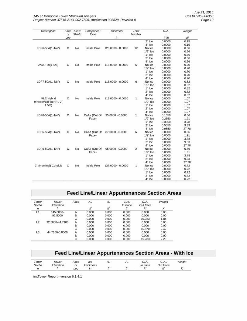
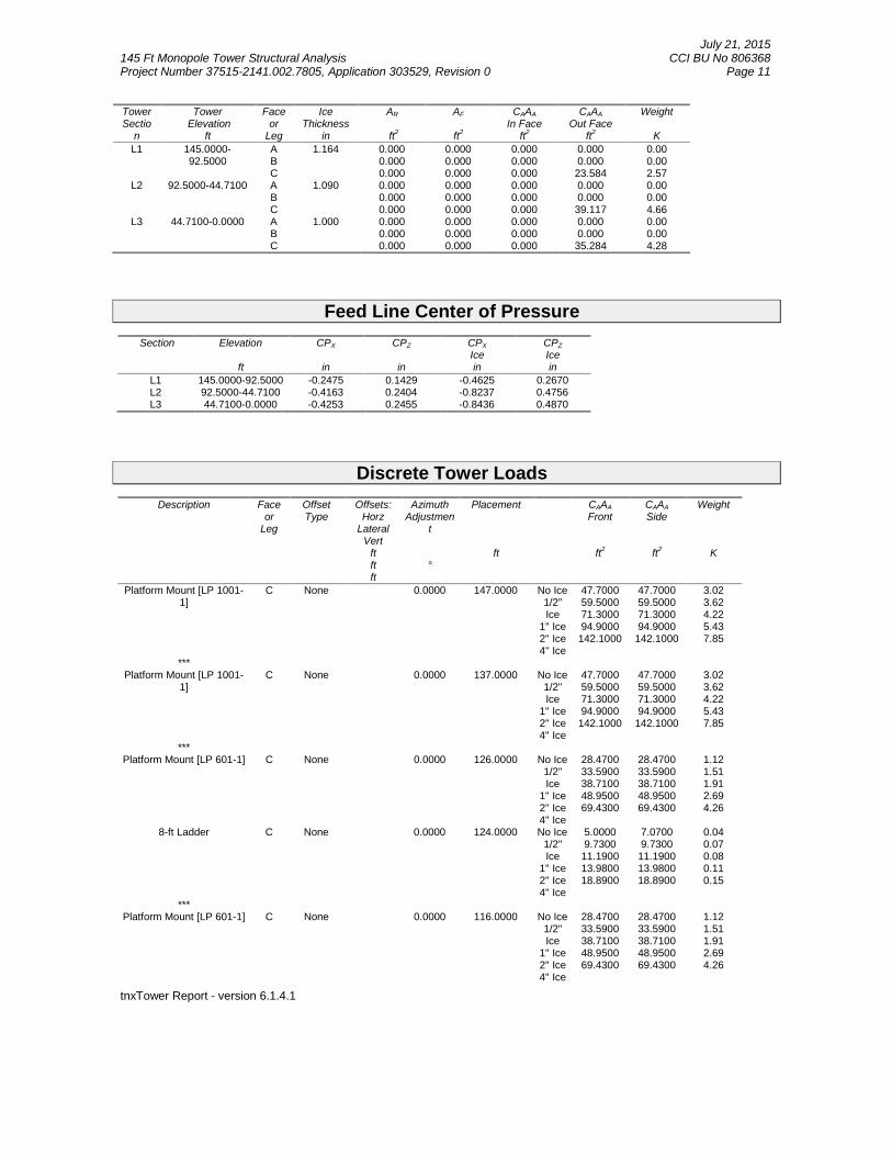
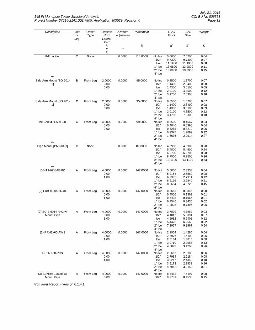
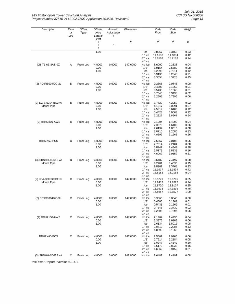
116LNX-6515DS-VTM w/ Mount Pipe 116LNX-6515DS-VTM w/ Mount Pipe 116LNX-6515DS-VTM w/ Mount Pipe 116RRUS 11 B12 116RRUS 11 B12 116RRUS 11 B12 1168-ft Ladder 114Ice Shield 1.5' x 2.0' 99Side Arm Mount [SO 701-1] 95Side Arm Mount [SO 701-1] 95RR65-18-02DP w/ Mount Pipe 95DA1900-39 957250.02 w/ Mount Pipe 877250.02 w/ Mount Pipe 877250.02 w/ Mount Pipe 87Pipe Mount [PM 601-3] 87DESIGNED APPURTENANCE LOADING
TYPE TYPEELEVATION ELEVATIONPlatform Mount [LP 1001-1] 147
DB-T1-6Z-8AB-0Z 147
(2) FD9R6004/2C-3L 147
(2) SC-E 6014 rev2 w/ Mount Pipe 147
(2) RRH2x60-AWS 147
RRH2X60-PCS 147
(3) SBNHH-1D65B w/ Mount Pipe 147
DB-T1-6Z-8AB-0Z 147
(2) FD9R6004/2C-3L 147
(2) SC-E 6014 rev2 w/ Mount Pipe 147
(2) RRH2x60-AWS 147
RRH2X60-PCS 147
(3) SBNHH-1D65B w/ Mount Pipe 147
(2) LPA-80063/6CF w/ Mount Pipe 147
(2) FD9R6004/2C-3L 147
(2) RRH2x60-AWS 147
RRH2X60-PCS 147
(3) SBNHH-1D65B w/ Mount Pipe 147
Platform Mount [LP 1001-1] 137
DTMABP7819VG12A 137
(2) RRUS-11 137
AM-X-CD-16-65-00T-RET w/ Mount Pipe 137
7020.00 137
7770.00 w/ Mount Pipe 137
(2) LGP13519 137
P65-17-XLH-RR w/ Mount Pipe 137
TT19-08BP111-001 137
DC6-48-60-18-8F 137
DTMABP7819VG12A 137
(2) RRUS-11 137
AM-X-CD-16-65-00T-RET w/ Mount Pipe 137
7020.00 137
7770.00 w/ Mount Pipe 137
(2) LGP13519 137
P65-17-XLH-RR w/ Mount Pipe 137
TT19-08BP111-001 137
DTMABP7819VG12A 137
(2) RRUS-11 137
7020.00 137
7770.00 w/ Mount Pipe 137
(2) LGP13519 137
(2) P65-17-XLH-RR w/ Mount Pipe 137
TT19-08BP111-001 137
Platform Mount [LP 601-1] 126
(4) DB844G65ZAXY w/ Mount Pipe 126
(2) GPS_A 126
(4) DB844G65ZAXY w/ Mount Pipe 126
(4) DB844G65ZAXY w/ Mount Pipe 126
8-ft Ladder 124
Platform Mount [LP 601-1] 116
ERICSSON AIR 21 B2A B4P w/ MountPipe
116
KRY 112 144/1 116
ERICSSON AIR 21 B2A B4P w/ MountPipe
116
KRY 112 144/1 116
ERICSSON AIR 21 B2A B4P w/ MountPipe
116
KRY 112 144/1 116
ERICSSON AIR 21 B4A B2P w/ MountPipe
116
ERICSSON AIR 21 B4A B2P w/ MountPipe
116
ERICSSON AIR 21 B4A B2P w/ MountPipe
116
LNX-6515DS-VTM w/ Mount Pipe 116
LNX-6515DS-VTM w/ Mount Pipe 116
LNX-6515DS-VTM w/ Mount Pipe 116
RRUS 11 B12 116
RRUS 11 B12 116
RRUS 11 B12 116
8-ft Ladder 114
Ice Shield 1.5' x 2.0' 99
Side Arm Mount [SO 701-1] 95
Side Arm Mount [SO 701-1] 95
RR65-18-02DP w/ Mount Pipe 95
DA1900-39 95
7250.02 w/ Mount Pipe 87
7250.02 w/ Mount Pipe 87
7250.02 w/ Mount Pipe 87
Pipe Mount [PM 601-3] 87
MATERIAL STRENGTHGRADE GRADEFy FyFu Fu
A572-65 65 ksi 80 ksi
TOWER DESIGN NOTES1. Tower is located in Hartford County, Connecticut.2. Tower designed for a 80.00 mph basic wind in accordance with the TIA/EIA-222-F Standard.3. Tower is also designed for a 37.60 mph basic wind with 1.00 in ice. Ice is considered to increase in thickness
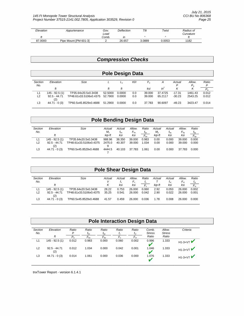
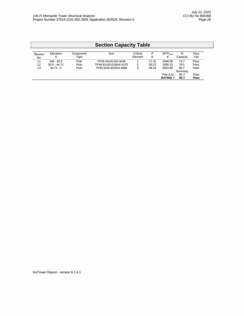
with height.4. Deflections are based upon a 60.00 mph wind.5. TOWER RATING: 80.7%
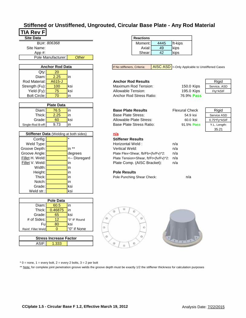
TIA Rev FSite Data Reactions
BU#: Moment: 4445 ft-kips
Site Name: Axial: 49 kips
App #: Shear: 42 kips
Other
If No stiffeners, Criteria: AISC ASD <-Only Applcable to Unstiffened Cases
Qty: 20
Diam: 2.25 in
Rod Material: A615-J Anchor Rod Results Rigid
Strength (Fu): 100 ksi Maximum Rod Tension: 150.0 Kips Service, ASD
Fillet H. Weld: <-- Disregard Plate Tension+Shear, ft/Ft+(fv/Fv)^2: n/a
Fillet V. Weld: in Plate Comp. (AISC Bracket): n/a
Width: in
Height: in Pole ResultsThick: in Pole Punching Shear Check: n/a
Notch: in
Grade: ksi
Weld str.: ksi
Diam: 60.5 in
Thick: 0.46875 in
Grade: 65 ksi
# of Sides: 12 "0" IF Round
Fu 80 ksi
Reinf. Fillet Weld 0 "0" if None
ASIF: 1.333
* 0 = none, 1 = every bolt, 2 = every 2 bolts, 3 = 2 per bolt
** Note: for complete joint penetration groove welds the groove depth must be exactly 1/2 the stiffener thickness for calculation purposes
Pole Manufacturer:
Stiffened or Unstiffened, Ungrouted, Circular Base Plate - Any Rod Material
Stress Increase Factor
Pole Data
Anchor Rod Data
Plate Data
Stiffener Data (Welding at both sides)
806368
CCIplate 1.5 - Circular Base F 1.2, Effective March 19, 2012 Analysis Date: 7/22/2015
Page 1 of 1By JWS Date 7/22/2015
ProjectClient
PROJ#
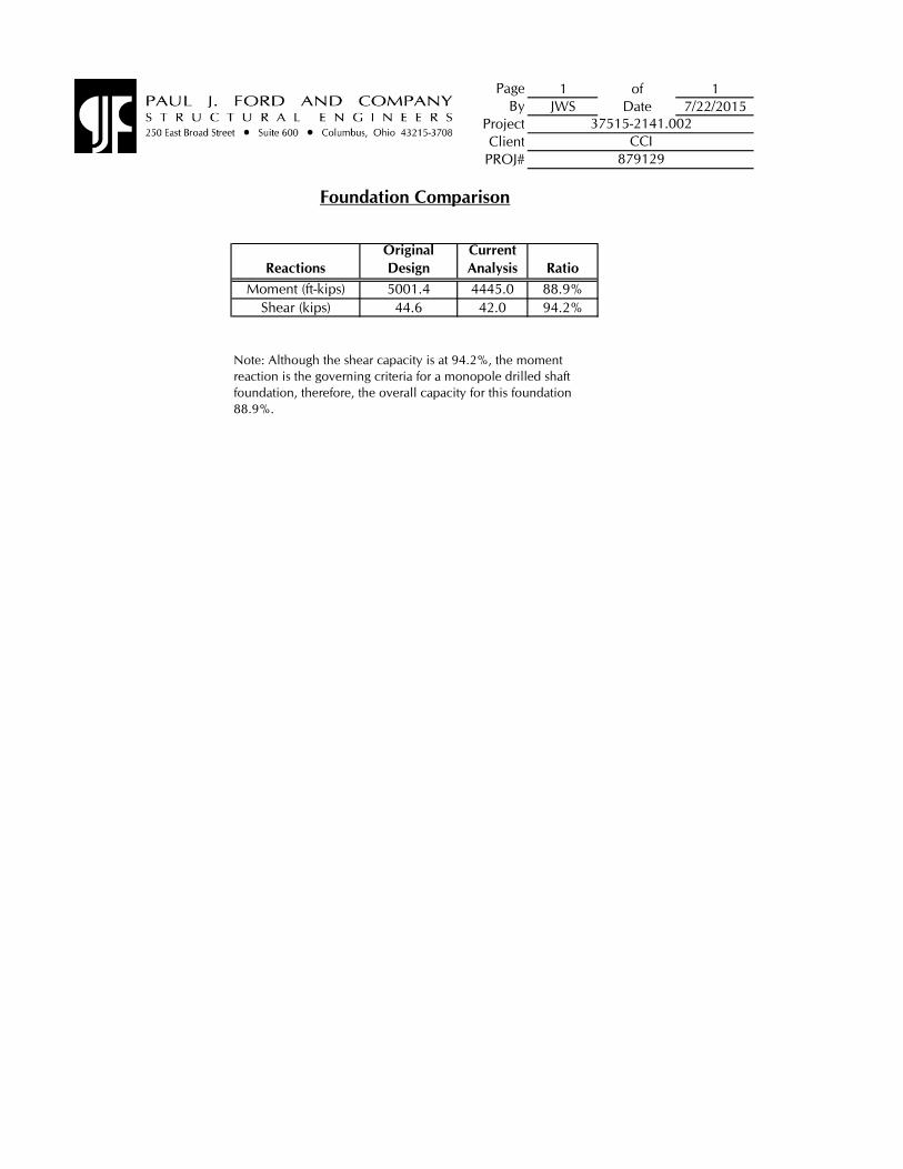
Reactions
Original
Design
Current
Analysis Ratio
Moment (ft-kips) 5001.4 4445.0 88.9%
Shear (kips) 44.6 42.0 94.2%
37515-2141.002CCI
879129
Foundation Comparison
Note: Although the shear capacity is at 94.2%, the moment
reaction is the governing criteria for a monopole drilled shaft
foundation, therefore, the overall capacity for this foundation
88.9%.
EBI Consulting environmental | engineering | due diligence
21 B Street . Burlington, MA 01803 . Tel: (781) 273.2500 . Fax: (781) 273.3311
RADIO FREQUENCY EMISSIONS ANALYSIS REPORT EVALUATION OF HUMAN EXPOSURE POTENTIAL
TO NON-IONIZING EMISSIONS
T-Mobile Existing Facility
Site ID: CT11248A
Glastonbury 374 Three Mile Road
Glastonbury, CT 06033
August 12, 2015
EBI Project Number: 6215004253
Site Compliance Summary
Compliance Status: COMPLIANT
Site total MPE% of FCC general public
allowable limit: 89.43 %
EBI Consulting environmental | engineering | due diligence
21 B Street . Burlington, MA 01803 . Tel: (781) 273.2500 . Fax: (781) 273.3311
August 12, 2015
T-Mobile USA Attn: Jason Overbey, RF Manager 35 Griffin Road South Bloomfield, CT 06002
Emissions Analysis for Site: CT11248A – Glastonbury
EBI Consulting was directed to analyze the proposed T-Mobile facility located at 374 Three Mile Road, Glastonbury, CT, for the purpose of determining whether the emissions from the Proposed T-Mobile Antenna Installation located on this property are within specified federal limits.
All information used in this report was analyzed as a percentage of current Maximum Permissible Exposure (% MPE) as listed in the FCC OET Bulletin 65 Edition 97-01and ANSI/IEEE Std C95.1. The FCC regulates Maximum Permissible Exposure in units of microwatts per square centimeter (µW/cm2). The number of µW/cm2 calculated at each sample point is called the power density. The exposure limit for power density varies depending upon the frequencies being utilized. Wireless Carriers and Paging Services use different frequency bands each with different exposure limits, therefore it is necessary to report results and limits in terms of percent MPE rather than power density.
All results were compared to the FCC (Federal Communications Commission) radio frequency exposure rules, 47 CFR 1.1307(b)(1) – (b)(3), to determine compliance with the Maximum Permissible Exposure (MPE) limits for General Population/Uncontrolled environments as defined below.
General population/uncontrolled exposure limits apply to situations in which the general public may be exposed or in which persons who are exposed as a consequence of their employment may not be made fully aware of the potential for exposure or cannot exercise control over their exposure. Therefore, members of the general public would always be considered under this category when exposure is not employment related, for example, in the case of a telecommunications tower that exposes persons in a nearby residential area.
Public exposure to radio frequencies is regulated and enforced in units of microwatts per square centimeter (μW/cm2). The general population exposure limit for the 700 MHz Band is approximately 467 μW/cm2, and the general population exposure limit for the PCS and AWS bands is 1000 μW/cm2. Because each carrier will be using different frequency bands, and each frequency band has different exposure limits, it is necessary to report percent of MPE rather than power density.
EBI Consulting environmental | engineering | due diligence
21 B Street . Burlington, MA 01803 . Tel: (781) 273.2500 . Fax: (781) 273.3311
Occupational/controlled exposure limits apply to situations in which persons are exposed as a consequence of their employment and in which those persons who are exposed have been made fully aware of the potential for exposure and can exercise control over their exposure. Occupational/controlled exposure limits also apply where exposure is of a transient nature as a result of incidental passage through a location where exposure levels may be above general population/uncontrolled limits (see below), as long as the exposed person has been made fully aware of the potential for exposure and can exercise control over his or her exposure by leaving the area or by some other appropriate means.
Additional details can be found in FCC OET 65.
CALCULATIONS
Calculations were done for the proposed T-Mobile Wireless antenna facility located at 374 Three Mile Road, Glastonbury, CT, using the equipment information listed below. All calculations were performed per the specifications under FCC OET 65. Since T-Mobile is proposing highly focused directional panel antennas, which project most of the emitted energy out toward the horizon, all calculations were performed assuming a lobe representing the maximum gain of the antenna per the antenna manufactures supplied specifications, minus 10 dB, was focused at the base of the tower. For this report the sample point is the top of a 6 foot person standing at the base of the tower.
For all calculations, all equipment was calculated using the following assumptions:
1) 2 GSM channels (PCS Band - 1900 MHz) were considered for each sector of the proposed installation. These Channels have a transmit power of 30 Watts per Channel
2) 2 UMTS channels (AWS Band – 2100 MHz) were considered for each sector of the proposed installation. These Channels have a transmit power of 30 Watts per Channel.
3) 2 LTE channels (AWS Band – 2100 MHz) were considered for each sector of the proposed
installation. These Channels have a transmit power of 60 Watts per Channel. 4) 1 LTE channel (700 MHz Band) was considered for each sector of the proposed installation.
This channel has a transmit power of 30 Watts. 5) All radios at the proposed installation were considered to be running at full power and were
uncombined in their RF transmissions paths per carrier prescribed configuration. Per FCC OET Bulletin No. 65 - Edition 97-01 recommendations to achieve the maximum anticipated value at each sample point, all power levels emitting from the proposed antenna installation are increased by a factor of 2.56 to account for possible in-phase reflections from the surrounding environment. This is rarely the case, and if so, is never continuous.
EBI Consulting environmental | engineering | due diligence
21 B Street . Burlington, MA 01803 . Tel: (781) 273.2500 . Fax: (781) 273.3311
6) For the following calculations the sample point was the top of a six foot person standing at the base of the tower. The maximum gain of the antenna per the antenna manufactures supplied specifications minus 10 dB was used in this direction. This value is a very conservative estimate as gain reductions for these particular antennas are typically much higher in this direction.
7) The antennas used in this modeling are the Ericsson AIR21 B4A/B2P & B2A/B4P) for 1900 MHz (PCS) and 2100 MHz (AWS) channels and the Commscope LNX-6515DS-VTM for 700 MHz channels. This is based on feedback from the carrier with regards to anticipated antenna selection. The Ericsson AIR21 B4A/B2P & B2A/B4P) have a maximum gain of 15.9 dBd at their main lobe. The Commscope LNX-6515DS-VTM has a maximum gain of 14.6 dBd at its main lobe. The maximum gain of the antenna per the antenna manufactures supplied specifications, minus 10 dB, was used for all calculations. This value is a very conservative estimate as gain reductions for these particular antennas are typically much higher in this direction.
8) The antenna mounting height centerline of the proposed antennas is 117 feet above ground
level (AGL). 9) Emissions values for additional carriers were taken from the Connecticut Siting Council
active database. Values in this database are provided by the individual carriers themselves.
All calculations were done with respect to uncontrolled / general public threshold limits.
EBI Consulting environmental | engineering | due diligence
21 B Street . Burlington, MA 01803 . Tel: (781) 273.2500 . Fax: (781) 273.3311
T-Mobile Site Inventory and Power Data
Sector: A Sector: B Sector: C Antenna #: 1 Antenna #: 1 Antenna #: 1
Make / Model: Ericsson AIR21 B4A/B2P Make / Model: Ericsson AIR21
EBI Consulting environmental | engineering | due diligence
21 B Street . Burlington, MA 01803 . Tel: (781) 273.2500 . Fax: (781) 273.3311
Summary
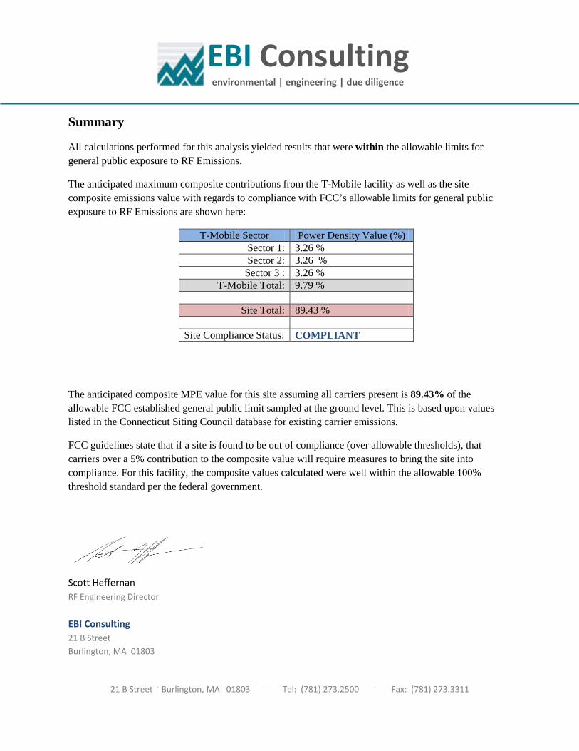
All calculations performed for this analysis yielded results that were within the allowable limits for general public exposure to RF Emissions.
The anticipated maximum composite contributions from the T-Mobile facility as well as the site composite emissions value with regards to compliance with FCC’s allowable limits for general public exposure to RF Emissions are shown here:
T-Mobile Sector Power Density Value (%) Sector 1: 3.26 % Sector 2: 3.26 % Sector 3 : 3.26 %
T-Mobile Total: 9.79 %
Site Total: 89.43 %
Site Compliance Status: COMPLIANT
The anticipated composite MPE value for this site assuming all carriers present is 89.43% of the allowable FCC established general public limit sampled at the ground level. This is based upon values listed in the Connecticut Siting Council database for existing carrier emissions.
FCC guidelines state that if a site is found to be out of compliance (over allowable thresholds), that carriers over a 5% contribution to the composite value will require measures to bring the site into compliance. For this facility, the composite values calculated were well within the allowable 100% threshold standard per the federal government.
Scott Heffernan RF Engineering Director EBI Consulting 21 B Street Burlington, MA 01803