'+11' 1 p" ... r t" .l fw l.l ·t\,_ v . .s.-J<-(C.v-, h.) c"'C' .. J J-..l) 1 U"-.I\J, <lt £ ( :.> .n l c I vJ,._ . FRiTZ ENGINEERING LABORATORY LIBRARY Recent Research on Composite Structures for Building and Bridge Applications Le-Wu Lu*, Roger R. Slutter*, Ben T. Yen*, Members, ASCE Continuing research has been carried ou·t at Lehigh University on composite structural members, joints, and overall systems. This paper summarizes the results of research on four selected subjects: composite beams with metal deck, strength of concrete anchors, composite beam-to- column joints and composite plate girders. The emphasis is on the results obtained during the last six years. Introduction At the first U.S.-Japan Joint Seminar on Composite and Mixed Construction held in Tokyo, Japan in January, 1978, a paper which summarized the findings ·of several major research programs carried out at Lehigh University on composite structures was presented (7). The paper dealt with composite structural members, joints, as well as assemblages which are parts of an overall building or bridge structure. The specific subjects included were: 1) composite beams with formed metal deck; 2) strength of stud anchors; 3) beam-to-column connections; 4) frame assemblages; 5) plate and box girders; and 6) fatigue. The research in most of these areas has continued since that seminar, and it is the purpose of this paper to present results of the recent work on topics 1, 2, 3 and 5. For topics 1 and 2 only, monotonic behavior will be considered, while for topic 3, the emphasis will be on cyclic behavior. Only composite plate girders will be discussed in topic 5. Composite Beams with Metal Deck The behavior of composite beams in the elastic range and the determination of the.ultimate strength have been well understood. The load-deflection, load-slip and shear connection force characteristics for the inelastic range, however, have not been fully developed. Com- puter programs that would approximate the general behavior of fairly ordinary composite beams have been used by many to solve particular beams. As one introduces a wider range of variables into the problem of characterizing the behavior of composite beams, the computer programs must be continually refined and the assumptions required to perform the modeling must be carefully reviewed. In the case of composite beams with metal deck the problem becomes complicated by the range of deck geometry available and the choice of possible shear connector patterns. *Professors of Civil Engineering, Lehigh University, Bethlehem, Pennsylvania 18015 1 Le-Wu Lu
Transcript
'+11' 1 p" ... r t" ~ .l
c,l,j~,\'t
fw ~~~J<v-.\~htl\.- l.l ·t\,_ v . .s.-J<-(C.v-, Ju 1 ~\J<\oy,.;,,y
Recent Research on Composite Structures for Building and Bridge Applications
Le-Wu Lu*, Roger R. Slutter*, Ben T. Yen*, Members, ASCE
Continuing research has been carried ou·t at Lehigh University on composite structural members, joints, and overall systems. This paper summarizes the results of research on four selected subjects: composite beams with metal deck, strength of concrete anchors, composite beam-tocolumn joints and composite plate girders. The emphasis is on the results obtained during the last six years.
Introduction
At the first U.S.-Japan Joint Seminar on Composite and Mixed Construction held in Tokyo, Japan in January, 1978, a paper which summarized the findings ·of several major research programs carried out at Lehigh University on composite structures was presented (7). The paper dealt with composite structural members, joints, as well as assemblages which are parts of an overall building or bridge structure. The specific subjects included were: 1) composite beams with formed metal deck; 2) strength of stud anchors; 3) beam-to-column connections; 4) frame assemblages; 5) plate and box girders; and 6) fatigue. The research in most of these areas has continued since that seminar, and it is the purpose of this paper to present results of the recent work on topics 1, 2, 3 and 5. For topics 1 and 2 only, monotonic behavior will be considered, while for topic 3, the emphasis will be on cyclic behavior. Only composite plate girders will be discussed in topic 5.
Composite Beams with Metal Deck
The behavior of composite beams in the elastic range and the determination of the.ultimate strength have been well understood. The load-deflection, load-slip and shear connection force characteristics for the inelastic range, however, have not been fully developed. Computer programs that would approximate the general behavior of fairly ordinary composite beams have been used by many to solve particular beams.
As one introduces a wider range of variables into the problem of characterizing the behavior of composite beams, the computer programs must be continually refined and the assumptions required to perform the modeling must be carefully reviewed. In the case of composite beams with metal deck the problem becomes complicated by the range of deck geometry available and the choice of possible shear connector patterns.
*Professors of Civil Engineering, Lehigh University, Bethlehem, Pennsylvania 18015
1 Le-Wu Lu
In order to model even the simplest composite beam with metal decking and partial shear connection, it was necessary to provide refined curves for the stress-strain behavior of steel and concrete and the force versus slip curves for shear connectors.
Certain limitations. must be_ placed on. the variety .of composite beams that can be modeled even with highly refined curves. Certain limitations are available from specifications and common practice~ but there are, nevertheless, members being constructed for which even the most refined model will barely suffice. For instance, it is difficult to model beams with metal decking greater than 3 inches in depth with the same model and input used for beams with 1 1/2", 2", or 3" decking. Shear connections of less than 50% are difficult to evaluate in all deck geometries although shear connections as low as 25% were modeled successfully in some instances.
The equation developed for evaluation of the shear connector strength for the AISC Specification provides some necessary limitations on rib geometry in order to provide proper factor of safety and control on deflections for the designer of beams. Consider the equation for the strength of shear connectors in a rib which follows:
0.85
IN (1)
In this equation N is the number of studs in a rib, H is the height of a stud, h is the height of the rib, w is the average rib width and Qsol is the capacity of a similar headed studs in a beam with a solid concrete slab. This equation excludes certain possible composite beams from-consideration not only because they represe~t poor construction, but also because they cannot be properly modeled. This equation provides a severe penalty for i~creasing the number of shear connectors in a rib. beyond two.. The addition of a .third co.nnec tor . provides little additional shear force and the use of four connectors provides the same result as two. The study of many beams with different rib geometries and shear connector patterns provided the evidence for this equation. The limit imposed on the number of shear connectors per rib is very necessary especially for 3" deep deck. Another limitation that is very real is the shear connector length versus rib height that is built into the equation. The use of shear connectors that are too short to be properly anchored in the compression area of the slab must be discouraged. The head geometry of studs is simply not suitable for proper anchorage in concrete if the above equation is not followed. When connectors are too short for anchorage the composite beam cannot be modeled except to test beams and developing a new model.
With the limitations imposed by the above equation, it is possible to model composite beams with metal decking not exceeding 3 inches in depth. In 1969, Robinson (9) demonstrated the applicability of existing methods for predicting the elastic behavior of composite beams with metal decking. In 1970, Fisher (3) introduced the concept that the rib strength could be modeled as a function of the Q solid strength.
2 Le-Wu Lu
This concept· has been successfully used for modeling as refinements in the modeling technique have been developed.
Comparison of predicted behavior with test results revealed basically three discrepancies. The first discrepancy was that the midspan deflection of beams was in satisfactory agreement but deflections at other points along the span were not being modeled properly. The second discrepancy was that the load versus slip behavior was not represented very well along the entire length of the beam. The third discrepancy was that the measured strains at points along the span were not predicted satisfactorily.
Modifications of the method of inelastic analysis of composite beams developed at McMaster University (8) was refined to try to minimize the above discrepencies (4). There were basically three modifications necessary for improved modeling with the existing approach. These were essentially three material performance characteristics that had to be modeled more carefully. Numerous test results had to be considered to develop the necessary refinements.
The first refinement was that the load-slip behavior of shear connectors had to be represented by a curve that reflected the entire behavior from elastic range to failure. Compromises were necessary here because it was realized that the end shear connector does not undergo the same loading conditions as an interior one. Pushout tests model the behavior of end connectors well, but interior connectors benefit from the compression stress in the slab and tend to be more stiff. The most important factor that had to be considered was the shear connectors in metal decking reach an ultimate load and then continue to defoim at decreasing loads. This declining portion of the curve had to be represented in order to completely describe the behavior of end connectors. Interior connectors on the other hand do not reach the declining portion of the curve in the course of a beam· test.
The second refinement was in the use of a proper stress-strain curve for structural· steel. It has long been assumed that residual stresses do not have a significant effect for beams in bending and an idealized curve has been used to represent beam behavior. However, with a composite beam residual stresses must be considered more carefully because the neutral axis is shifted toward the slab and the residual stress pattern is no longer symmetrical about the neutral axis. Also as the composite beam becomes inelastic the concrete slab tends to shed load which the steel beam must pick up and the bottom flange of the steel beam goes into strain hardening before the ultimate load is reached. Fortunately, the refinements needed in this behavior are much less important than the load-slip behavior. One can model a beam rather successfully without treating residual stress and strain hardening very precisely.
The third refinement is in the concrete stress-strain curve. It must be realized that concrete has a declining portion of the stressstrain curve which becomes important in some instances.
3 Le-Wu Lu
It happens to be important for composite beams with metal deck and is especially important when the concrete is structural lightweight concrete. The reinforcement in a composite beam is sufficient to utilize the declining position of the concrete stress-strain curve and should be included in the analysis.
The curves in Fig. 1 show the types of curves used in modeling composite beams with metal deck. The upper graph shows concrete curves, the middle graph shows steel curves and the lower graph shows load versus shear connector force curves. If various curves are selected from the three graphs, the load versus midspan deflection curves shown in Fig. 2 can be obtained. The circles represent data from an actual beam test. It will be noticed that the model that best characterizes the behavior of this beam results from using curve C2 for concrete, S2 for steel and SC3 for the shear connection behavior. None of the simple curves commonly used as idealized curves can be used in obtaining a good representation.
The proper representation of the load-deformation for shear is important. This is necessary to obtain overall agreement for deflections, slips and strains over the entire span length. The other refinements are of less importance but do contribute to obtaining the proper shape of the load-deflection curve well into the inelastic region. If any of the refinements are dropped the predicted curve will not remain in good agreement with the test curve, especially the inelastic region.
Concrete Anchors
The exact nature of the loading on concrete anchors in service is usually unknown. A combination of tension and shear is the usual loading condition but the amounts are often unknown. This situation led to the development of interaction curves showing the strength of anchors under . combined .loading. However,. the se-ve_re _loading on concrete arichors results in questions that often arise concerning the strength of anchors under adverse conditions.
One of the problems that often occurs is the question of bend testing of anchors. Most specifications provide for testing the soundness of stud shear connector welds by bending the shear connectors 15° from the normal to the plate surface with a hammer. This test has been carried over to concrete anchors, but the application of this testing procedure generates many questions.
Although everyone accepts readily that the 15° bend does not adversely affect the strength of shear connectors, they are not so convinced that this is true for the longer concrete anchors. An even more difficult question arises when the anchor was inadvertently bent more than 15°.
On several occasions it has been necessary to perform tests to demonstrate the strength of bent anchors. The test results are interesting because some general guidelines can be given that enable engineers to develop answers to these questions.
4 Le-Wu Lu
In the first· testing program, some 1/2" diameter headed studs were bent 30° which seemed like a reasonable limit for an overzealous inspector.
After giving the results for 30° bends to some engineers, the question of 45° bends were raised. Immediately more tests were required. Next, 3/4" diameter headed studs were tested, but to date no one has asked for results on larger angles.
The 1/2" diameter connectors bent 30° had an ultimate strength of 95% of the strength of similar studs that were not bent. When the 3/4" diameter connectors that were bent 45° were tested the strength was found to be 75% of the strength of similar straight anchors. These relative strengths are slightly higher than one might use in design because in both instances the anchors were slightly longer than the minimum accepted embedment length of 8 diameters.
If one considers anchors that are exactly the minimum embedment length, then bent anchors can be considered to have a strength that is proportional to the embedment depth of the bent stud divided by the embedment length of the straight stud times the strength of the straight stud. A simple rule is that the strength is proportional to the cosine of the angle of bend. Thus:
An anchor bent 15° has 96.6% of full strength An anchor bent 20° has 94.0% of full strength An anchor bent 30° has 86.6% of full strength An anchor bent 40° has 76.6% of full strength
It is not 'intended that this information provide justification for testing by bending more than 15°. Rather the above provides a quick analysis of anchor strength when bending is found to be more than the specified 15 °.
Another question that has caused many people to question concrete anchor values is the presence of cracks in concrete. Every time a novice tests a composite beam, he becomes concerned about the longitudinal crack that forms down the center of the beam passing through the line of shear connectors. Some investigators have reported that this crack reduces the strength of the shear connectors. This is undoubtedly true. However, every beam ever tested had this crack. Therefore, when shear connector values were derived from test results, the values were determined from cracked beams. Since the tee beam that one tests is a plate structure, this crack always forms. The amount of transverse steel required to "prevent" this crack is very large. As a result the test beams have generally contained typical reinforcement and that is the assumption that we must keep in mind when using shear connector values. Only if one were to use no slab reinforcement is it necessary to be concerned about the strength of the shear connectors.
The situation with regard to concrete anchors is rather different because the strength of concrete anchors has been developed from tests in uncracked blocks of concrete. These blocks have also been unreinforced whereas anchors are most commonly used in reinforced concrete members.
5 Le-Wu Lu
The strength. of anchors in cracked concrete could only be determined by testing and this was done for a limited number of sized of anchors.
Fig. 3 shows two discs of reinforced concrete spaced apart by timbers around the perimeter. A compression load applied by the testing machine was applied as a point load at the center of the discs. Thus the top surface of the lower disc was stressed in biaxial tension. Anchors were tested in tension as shown in Fig. 4 and in shear as shown in Fig. 5 with the concrete slab unstressed and stressed in biaxial tension. Reinforcement in the disc was placed below the test surface, an amount equal to the length of the anchors. Anchors were positioned so that they were in the centers of the space between reinforcing bars. Thus the anchors were placed in unreinforced cracked concrete when the slab was stressed. Fig. 6 shows the cracked slab and test anchor locations. The testing programs included the folfowing anchors:
5/8" x 4" Headed 3/8" x 4" Bent anchors 5/8" x 5 1/4" Headed 1/2" x 5 1/4" Bent anchors
Each type of anchor was tested in both shear and tension with and without the concrete being stressed in biaxial tension. A total of 46 tests were made with 28 tests made with concrete in biaxial tension.
The. conclusions from this testing program were as follows:
1. Full embedment length was provided for 3/8" x 4" bent, 1/2" x 5 1/4" bent and 5/8" x 5 1/4" headed anchors, but not for 5/8" x 4" headed anchors.
~. All anchors had the same nominal strength in shear for the concrete in tension and ·unstressed.
3. The 3/8" x 4;, bent, and the 5/8" x 5 1/4" headed anchors had the same strength in tension for the concrete in tension and unstressed.
4. The 1/2" x 5 1/4" bent studs pulled out at a load lower than the strength of the anchor indicating sufficient embedment in both concrete stressed in tension and unstressed concrete.
5. It was observed that a crack through the head of a stud altered the shape of the load-deformation curve but did not reduce the ultimate strength.
6. It appears from these tests that full embedment is necessary for developing the full anchor strength. If this is achieved the ultimate strength is not reduced in shear or tension.
This testing program did not include concrete anchors larger than 5/8" diameter and therefore does not provide test results directly applicable to the most commonly used sizes of anchors.
6 Le-Wu Lu
It is also important to point out that the slabs were heavily reinforced even though there was no reinforcement in the portion of the slabs where anchors were embedded. Thus crack control was provided by the reinforcement, and this is probably necessary for the validity of these results. It is felt that much lighter reinforcement placed between the anchor heads and the surface of the slab would provide similar test results. The reason why the cracks do not reduce the strength of the anchors appears to be that they do not coincide with the conical failure surface that develops around an anchor. Even though a crack may pass through a failure core, it does not alter the failure sufficiently to reduce the ultimate strength.
Composite Beam-To-Column Joints with Panel Zone Deformation
The paper presented at the first seminar gave the results of an experimental and analytical study of the monotonic load behavior of composite beam-to-column connections.* In that study, the composite beams and their connections were subjected to positive moment only. The results show that the ultimate strength of the composite members is almost independent of the slab width, but in proportion to the slab thickness. The study also indicates that the available ductility is quite adequate to permit-the application of the plastic design concept to composite frames. Methods of plastic analysis which take into account the contribution of floor slab have been developed (2).
Since the research was intended primarily to study the behavior of composite connections, not joint assemblages, the test specimens had very strong columns and web panels, which behaved rigidly throughout the tests. Also, the beams were always subjected to positive momen.t. There is, therefore, the need to extend the study to include overall joint assemblages with flexible columns and web panels and subjected to both positive and negative moments. The problems of load reversal is an important concern in seismic-resistant design .
. An on-going study at Lehigh, ~hich i~ part of the u.s:-Japan Cooperative Research Program in Earthquake Engineering, includes cyclic load tests of three composite beam-to-column joint assemblages. The first one is an exterior joint with the beam connected directly to the column flange. This specimen is designated as EJ-FC (exterior joint-flange connection). The second specimen is an interior joint with two beams connected to the column flanges and is designatedas IJ-FC. The third specimen, designated as EJ-WC, is an exterior joint in which the beam is "web connected" to the column. The specimens are full size and are replicas of the joints of the six-story prototype steel structures which have been tested at the Japanese Building Research Institute in Tsukuba, Japan. All the specimens have welded flanges and bolted webs. The results of the EJ-FC specimen are presented here as "advance information" because the entire program is still in progress.
*A distinction is made here between connection and joint. According to the Uniform Building Code (5), a joint is the entire assemblage at the interaction of two or more members, and in connection consists of only those elements that connect a member to the joint.
7 Le-Wu Lu
The dimensions and member sizes of the specimen are shown in Fig. 7. The test was conducted with a program of reversed and repeated displacements applied near the tip of the beam and the load P corresponding to each displacement was determined by a load cell. Measurements of the deflections and strains at selected locations were made after each displacement increment. In addition, the shear distortion of the panel zone was carefully measured with dials. The specimen was subjected to a maximum beam tip displacement of 6 inches before fracture occurred in both beam flanges near the coped holes. Fig. 8 shows the fracture of the upper flange, which precipitated failure of the test specimen.
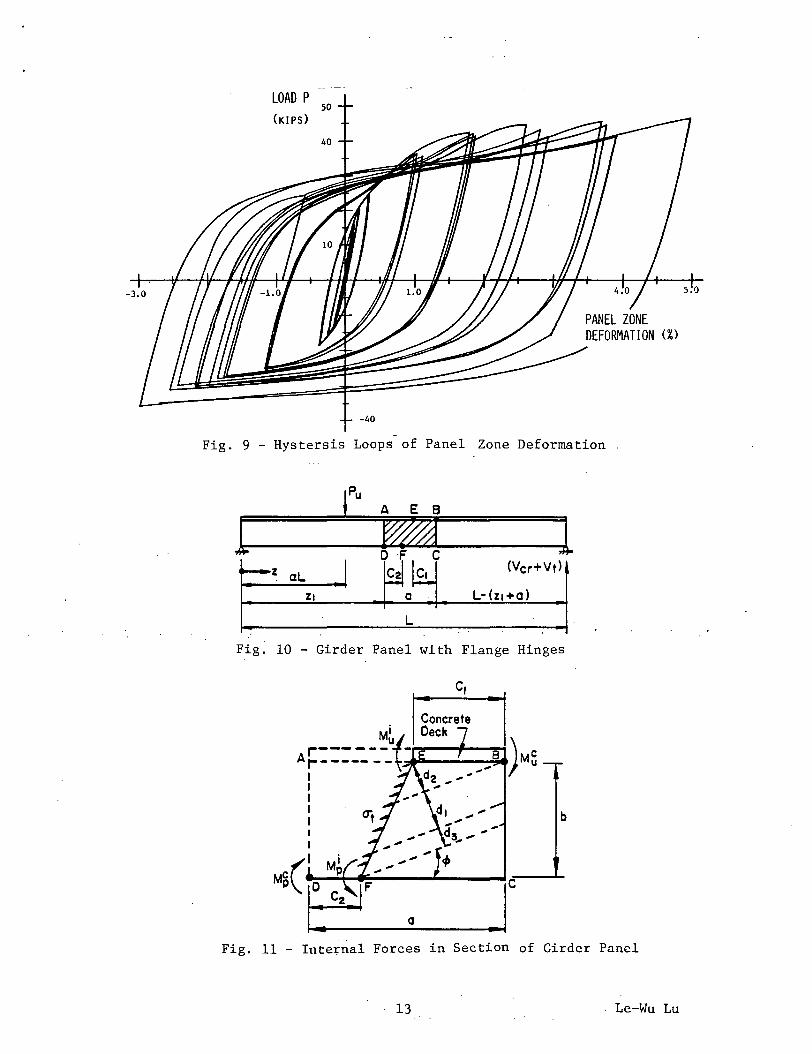
The hysteretic relationships between the load P and the angular distortion of the panel zone are given in Fig. 9. Since the joint was subjected to different amounts of positive and negative moment for the same displacement, the response of the panel zone was also different. The hysteresis loads are generally unsymmetrical (about the origin) and are somewhat "pinched" at large distortions caused by positive moment. The results indicate that the available panel zone ductility of the joint is quite substantial.
Strength of Composite Plate Girders
The load carrying capacity of steel-concrete composite plate girders has been studied recently. The basic approach of evaluating girder strength by web panel and flange behavior has been adopted.
When a section of a composite plate girder is subjected to bending moment only, the phenomena of web. plate buckling and non-composite steel flange failure are similar to those of steel plate girders. Failure of the composite girder flange, however, is governed by crushing of the concrete and yielding of the adjacent steel plate. This phenomenon is identical.to that of a composite beam flange, and has been well stud~ed
Under the combined action of shear force and bending moment, the web of a composite girder could develop post-buckling strength. The failure mechanism of the composite plate girder panel includes the formation of "plastic" hinges in the flanges (1). Figure 1 shows a girder panel, subjected to both moment and shear, has four flange hinges.
The strength of the panel of Fig. 1 can be evaluated through consideration of equilibrium of internal forces, (Fig. 2). The strength of plastic hinges in the steel flange can be computed by the traditional procedure. The ultimate moment of the composite flange must be calculated through a trial-and-error procedure involving the determination of the neutral axis.
A number of cases have been examined by computer analysis. Table 1 lists some example results. It is obvious that smaller flanges fail before the web, and longer web panels have lower strengths.
Experimental verification is needed of the analytical procedure.
8 Le-Wu Lu
Table 1 - Shear· Strength (V /V ) of Composite Plate Girders u y
Panel Aspect Ratio
0.75 1.0 1. 25 1. 50
Small Flange, Flange Failure 0.463 0.451 0.441 0.430
Presented in this paper are the results of four recent studies carried out at Lehigh University on composite members and joints. The specific topics included are: composite beams with metal deck, strength of concrete anchors, beam-to-column'joints and composite plate girders. The purpose of the paper is to update the information given in a previous paper which was presented at the first U.S.-Japan Joint Seminar on Composite and Mixed Construction. Much of the results presented here were obtained after that seminar.
In the previous paper, a strong appeal was made for a U.S.-Japan cooperative effort in the area of composite and mixed structures. It is gratifying to note that some join~ research in this area has indeed been carried out as part of the U.S.-Japan Cooperative Program in Earthquake Engineering. In fact, a number of papers presented at this seminar are the results of this effort.·
Composite structu·res showed much promise in buildings and bridge applications in the last 25 years. There has been a continuing effort to improve the existing specifications or to develop new specifications by incorporating the latest research results and design experience. These specifications will play an increasingly important role in the successful construction of composite structures.
Appendix - References
1. Chen, Y.S. and Yen, B.T., "Ultimate Strength of Composite Box Girders in Flexure", Fritz Engineering Laboratory Report No. 380-15, April, 1980.
2. duPlessis, D.P. and Daniels, J.H., "The Interaction of Floors and Frames in High Rise Buildings", Fritz Engineering Laboratory Report 374.4, Lehigh University, August, 1974.
3. Fisher, J.W., "Design of Composite Beams with Formed Metal Deck", Engineering Journal, American Institute of Steel Construction, Vol 7, No. 2, July, 1970, pp. 88-96.
9 Le-Wu Lu
4. Grant, J.A., Jr., "Determination of Connector and Beam Behavior for Composite Beams with Deck Formed Slabs", Ph.D. Dissertation, Lehigh University, 1980.
5. ICBO, "Uniform Building Code", International Conference of Building Officials, Whittier, California, 1982.
6. Lee, S.J., and Lu, L.W., "Cyclic Behavior of Composite Beam-toColumn Joints", Fritz Engineering Laboratory Report No. 467.4, Lehigh University (in preparation).
7. Lu, L.W., Slutter, R.G. and Yen, B.T., "Research on Composite Structures for Building and Bridge Applications''~ in "Developments in Composite and Mixed Construction", Proceedings of the U.S.-Japan Seminar on Composite Structures and Mixed Structural Systems, GIHODO Publishing Co., Tokyo, Japan, pp. 3-18.
8. Ma, K.P., "Inelastic Analysis of Composite Beams with Partial Connections", M.S. Thesis, McMaster University, Oct. 1973.
9. Robinson, H., "Preliminary Investigation of a Composite Beam with Ribbed Slab Formed by Cellular Steel Decking", Engineering Department Report No. 35, McMaster University, Oct. 1969.
10. Slutter, R.G. and Driscoll, Jr., G.C., "Flexural Strength of Steel-Concrete Composite Beams", Journal of the Structural Division, ASCE, Vol. 91, No. ST2, April, 1965, pp. 71-99.
MPo
100
Concrete Stress-Strain Relationships
0.003 0.004
:'Cs,-- --52
Steel Stress- Strain Relationships
0.01 0.02 0.03 0.04 E, mm/mm
y, mm
Fig. 1 - Combinations of Relationships Available
LOAD kN
----------;--:-:------
MIDSPAN DEFLECTION, mm
0 0
Cl, 51,$ SCI
C2, 52,$ SC2
C2, 52,$ SC3
C2, 52,~ SC4
Fig. 2 - Load-Deflection Beahvior of a Beam Predicted by Combinations of Stress-Strain Relationships
10 Le-Wu Lu
Fig. 3 - Test Discs Loaded in Biaxial Tension
Fig. 4 - Tension Test of Anchor
Fig. 5 - Shear Test of Anchor
Fig. 6 - Disc . Showing Crack Pattern After Test
11 Le-Wu Lu
!'... /
0 .... "'
.... "'
....
Wl8 X 35
p
SPECIMEN EJ-FC
'· 90.0" .I~·~"
Fig·. 7 - Dimensions of Member Sizes of EJ-FC
/
"
... ~··
~COLUMN
//BEAM I
' WEB PJ l !., LATE
.1'
,{
""---CRACK
/CRACK
t-_/ \'
I I j I I
12
Fig. 8 - Details of Fracture of Upper Flange
Le-Wu Lu
LOAD P
Fig. 9 - Hystersis Loops of Panel Zone Deformation
ru A E 8 r Wda l D F c z aL
(Vcr+Vt)
Zl 0 L-(z,+o)
L
Fig. 10 - Girder Panel with Flange Hinges
c,
b
a J Fig. 11 - Inte~nal Forces in Section of Girder Panel
13 . Le-Wu Lu
KEY W 0 R D S
Composite beams, metal deck, shear connector, combined loading,
composite slab, joint, cyclic load, panel zone deformation, plate


![y5 *-31 IOOg¥VJ (1 Bog) (450g) 550tY-t-YÄî-* 2.7e …1/\y5 *-31 IOOg¥VJ (1 Bog) (450g) 550tY-t-YÄî-* 2.7e (400g) 380 (200B) 580 (500B) 580 (F]240g) 499 (420g) (700mÆ) 1,290](https://static.documents.pub/doc/80x56/5fca166bc14e9710a730fcae/y5-31-ioogvj-1-bog-450g-550ty-t-y-27e-1y5-31-ioogvj-1-bog.jpg)


![s,Qt~ = w zÉ s>= v / VJ½ · AC §±¦ ¢¼«¥º¡70cm 20cm s,Qt~ = w zÉ s>= v / VJ½ “>@ª¸¦ tv >= N6» . A sC OH t3 t= U] u](https://static.documents.pub/doc/80x56/600ce78b86167449f339bed5/sqt-w-z-s-v-vj-ac-70cm-20cm-sqt-w-z-s.jpg)
