Right-hand and left-hand sides are determined by facing in the direction of forward travel
Revolutions Per Second
Revolutions Per Minute
Society of Automotive Engineers
Kubota Reverse Awareness System
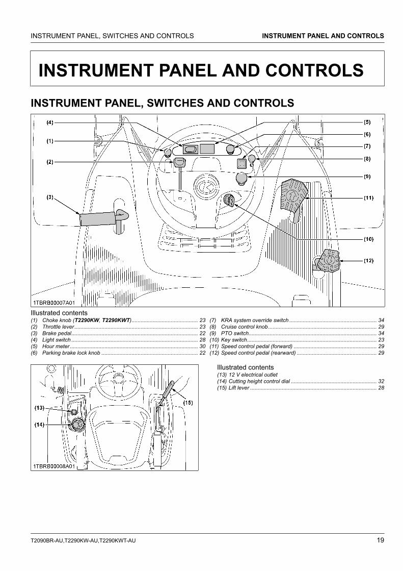
UNIVERSAL SYMBOLSAs a guide to the operation of your machine, various universal symbols have been utilized on the instruments and controls. The symbols are shown below with an indication of their meaning.
Safety Alert Symbol
Gasoline Fuel
Brake
Parking Brake
Engine-Stop
Engine-Run
Starter Control
Power Take-Off Clutch Control-Off Position
Power Take-Off Clutch Control-On Position
Cutting Height
Mower-Lowered position
Mower-Raised position
Headlight
Headlight-ON
Headlight-OFF
Fast
Slow
Engine Speed Control
Choke
Cruise Control
KUBOTA Corporation is ···Since its inception in 1890, KUBOTA Corporation has grown to rank as one of the major firms in Japan.
To achieve this status, the company has through the years diversified the range of its products and services to a remarkable extent, until today, 30 plants and 35,000 employees produce over 1,000 different items, large and small.
All these products and all the services which accompany them, however, are unified by one central commitment. KUBOTA makes products which, taken on a national scale, are basic necessities. Products which are indispensable, products intended to help individuals and nations fulfill the potential inherent in their environment. For KUBOTA is the Basic Necessities Giant.
This potential includes water supply, food from the soil and from the sea, industrial development, architecture, construction and transportation.
Thousands of people depend on KUBOTA's know-how, technology, experience and customer service. You too can depend on KUBOTA.
FOREWORDYou are now the proud owner of a KUBOTA LAWN TRACTOR. This machine is a product of KUBOTA's quality engineering and manufacturing. It is made of excellent materials and under a rigid quality control system. It will give you long, satisfactory service. To obtain the best use of your machine, please read this manual carefully. It will help you become familiar with the operation of the machine and contains many helpful hints about machine maintenance. It is KUBOTA's policy to utilize, as quickly as possible, every advance in our research. The immediate use of new techniques in the manufacturing of products may cause some small parts of this manual to become outdated. KUBOTA distributors and dealers will have the most up-to-date information. Please do not hesitate to consult them.
SAFETY FIRST
IMPORTANT :
NOTE :
Indicates an imminently hazardous situation which, if not avoided, will result in death or serious injury.
Indicates a potentially hazardous situation which, if not avoided, could result in death or serious injury.
Indicates a potentially hazardous situation which, if not avoided, could result in minor or moderate injury.
Indicates that equipment or property damage could result if instructions are not followed.
Gives helpful information.
This symbol, the industry's safety alert symbol, is used throughout this manual and on labels on the machine itself to warn of the possibility of personal injury. Read these instructions carefully. It is essential that you read the instructions and safety regulations before you attempt to assemble or use this unit.
DANGER :
WARNING :
CAUTION :
CONTENTSSAFE OPERATION......................................................................................................................5SERVICING OF MACHINE........................................................................................................15
WARRANTY........................................................................................................................................................ 16SCRAPPING THE MACHINE AND ITS PROCEDURE...................................................................................... 16
INSTRUMENT PANEL AND CONTROLS.................................................................................19INSTRUMENT PANEL, SWITCHES AND CONTROLS ..................................................................................... 19MOWER.............................................................................................................................................................. 20
MOWER MOUNTING.................................................................................................................21ATTACHING THE MOWER ................................................................................................................................ 21
1. Mounting the mower deck ......................................................................................................................... 21ADJUSTING THE MOWER DECK (FOR BEAUTIFUL FINISH CUT) ................................................................ 21DISMOUNTING THE MOWER DECK ................................................................................................................ 21
OPERATING THE ENGINE .......................................................................................................22STARTING THE ENGINE ................................................................................................................................... 22
STOPPING THE ENGINE................................................................................................................................... 24CHECKING SAFETY SYSTEMS........................................................................................................................ 24
1. Checking engine start system ................................................................................................................... 242. Checking OPC system .............................................................................................................................. 253. Checking PTO control system ................................................................................................................... 25
CHECK WHILE OPERATING THE ENGINE ...................................................................................................... 25WARMING UP THE ENGINE ............................................................................................................................. 26
1. Warm-up and transmission oil in the low temperature range .................................................................... 26JUMP STARTING ............................................................................................................................................... 26
OPERATING THE MACHINE ....................................................................................................27OPERATING A NEW MACHINE......................................................................................................................... 27
1. Changing lubricating oil for new machine.................................................................................................. 27STARTING THE MACHINE ................................................................................................................................ 27
1. Operator's seat .......................................................................................................................................... 282. Light switch................................................................................................................................................ 283. Lift lever ..................................................................................................................................................... 284. Throttle lever.............................................................................................................................................. 285. Parking brake ............................................................................................................................................ 296. Speed control pedal................................................................................................................................... 297. Cruise control device ................................................................................................................................. 29
STOPPING THE MACHINE................................................................................................................................ 30CHECK DURING DRIVING ................................................................................................................................ 30
1. Hour meter................................................................................................................................................. 30PARKING THE MACHINE .................................................................................................................................. 30TRANSPORTING THE MACHINE...................................................................................................................... 31
1. Hydrostatic transaxle bypass rod .............................................................................................................. 31
OPERATING THE MOWER.......................................................................................................32MOWING TIPS.................................................................................................................................................... 32
T2090BR-AU,T2290KW-AU,T2290KWT-AU 1
ADJUSTING THE CUTTING HEIGHT................................................................................................................ 321. Cutting height control dial .......................................................................................................................... 32
OPERATING THE MOWER................................................................................................................................ 331. KRA system normal operating mode......................................................................................................... 342. PTO switch ................................................................................................................................................ 343. KRA system override mode....................................................................................................................... 34
MAINTENANCE.........................................................................................................................36SERVICE INTERVALS........................................................................................................................................ 36LUBRICANTS AND FUEL................................................................................................................................... 40
PERIODIC SERVICE .................................................................................................................42OPEN THE HOOD.............................................................................................................................................. 42
DAILY CHECK .................................................................................................................................................... 421. Checking the engine oil level ..................................................................................................................... 432. Checking the amount of fuel and refueling ................................................................................................ 433. Checking cooling air intake screen............................................................................................................ 444. Oiling ......................................................................................................................................................... 45
EVERY 25 HOURS............................................................................................................................................. 461. Cleaning air cleaner................................................................................................................................... 46
EVERY 50 HOURS............................................................................................................................................. 471. Checking brake pedal ................................................................................................................................ 472. Checking the tire pressure......................................................................................................................... 47
8.1 Charging the battery........................................................................................................................... 538.2 Storing the battery.............................................................................................................................. 53
9. Replacing air cleaner paper element ......................................................................................................... 5310. Checking fuel filter ................................................................................................................................... 5411. Cleaning air cleaner paper element (T2290KW, T2290KWT) ................................................................. 55
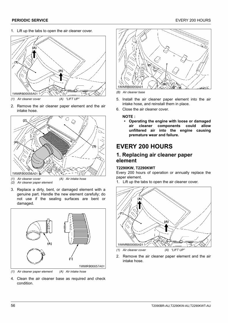
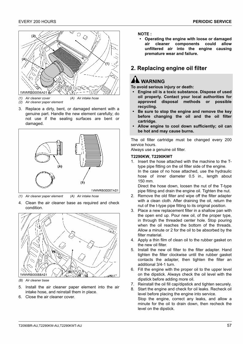
EVERY 200 HOURS........................................................................................................................................... 561. Replacing air cleaner paper element ......................................................................................................... 562. Replacing engine oil filter .......................................................................................................................... 57
EVERY 300 HOURS........................................................................................................................................... 581. Cleaning combustion chamber (T2290KW, T2290KWT) .......................................................................... 582. Checking engine valve seats and clearance ............................................................................................. 58
EVERY 500 HOURS........................................................................................................................................... 581. Adjusting the electric clutch ....................................................................................................................... 582. Cleaning combustion chamber (T2090BR) ............................................................................................... 59
EVERY 1 YEAR .................................................................................................................................................. 601. Checking fuel line ...................................................................................................................................... 602. Replacing spark plug ................................................................................................................................. 613. Checking engine valve clearance.............................................................................................................. 61
EVERY 4 YEARS................................................................................................................................................ 61
2 T2090BR-AU,T2290KW-AU,T2290KWT-AU
1. Replacing fuel lines ................................................................................................................................... 61SERVICE AS REQUIRED................................................................................................................................... 61
1. Replacing fuses ......................................................................................................................................... 612. Replacing bulbs ......................................................................................................................................... 613. Checking and replacing blades ................................................................................................................. 614. Replacing the mower belt .......................................................................................................................... 62
1. Anti-scalp rollers ........................................................................................................................................ 642. Leveling the mower deck (side-to-side) ..................................................................................................... 643. Leveling the mower deck (front-to-rear) .................................................................................................... 65
GENERAL TORQUE SPECIFICATION .............................................................................................................. 67TIGHTENING TORQUE CHART ........................................................................................................................ 68
STORAGE..................................................................................................................................69STORING THE MACHINE.................................................................................................................................. 69REMOVING THE MOWER FROM STORAGE................................................................................................... 69
SAFE OPERATIONCareful operation is your best insurance against anaccident.The owner/user can prevent and is responsible foraccidents or injuries occurring to themselves, otherpeople or property. Read and understand this manualcarefully before operating the machine. All operators,no matter how much experience they may have had,must read this and other related manuals beforeoperating the machine or any implement attached to it.It is the owner's obligation to instruct all operators insafe operation.If the operator(s) or mechanic(s) cannot understand thecontents, it is the owner's responsibility to explain thismaterial to them. This mowing machine is capable ofamputating hands, feet and throwing objects. Failure toobserve the following safety instructions could result inserious injury or death.
BEFORE OPERATING THEMACHINEKnow your equipment and its limitations. Read allinstructions in this manual before attempting to startand operate the machine.
1. General• Know the controls and how to stop quickly.• Pay special attention to the safety labels on the
machine itself.• The exhaust gas from the muffler is very hot. To
prevent fire, do not expose dry grass, mowedgrass, oil or any other combustible materials toexhaust gas. Keep the engine and muffler clean allthe time.
• Do not wear loose, torn, or bulky clothing aroundthe machine. The clothing may catch on movingparts or controls, leading to the risk of an accident.Wear and use any additional safety items such as ahard hat, safety boots or shoes, eye and hearingprotection, gloves and so on, as appropriate orrequired.
• Do not operate the machine or any attachmentswhile under the influence of alcohol, medication,controlled substances or when fatigued.
• Check brakes and other mechanical parts forcorrect adjustment and wear. Replace worn ordamaged parts promptly. Check the tightness of allnuts and bolts regularly.(See MAINTENANCE on page 36.)
• Keep the machine and attachments in goodoperating condition and keep safety devices inplace and in proper working condition.
• This machine is equipped with many safetydevices. Do not attempt to remove or alter them.
• Keep all shields and guards in place. Replace allmissing or damaged items for your safety.
• Do not allow any bystanders around or nearmachine during operation.Be sure the area is clear of other people beforemowing.Stop machine if anyone enters the area.
• Before allowing other people to use your machine,explain proper operation to them and have themread this manual before operation.
• Do not allow passengers or non-qualified operatorson the machine at any time. You must operate themachine from the seat only.
• Carefully check the area to be mowed and clearany objects such as rocks, bottles, cans, toys, etc.,that may damage the mower, the grass catcher orcause personal injury.
• Keep your machine clean. Accumulations of dirt,grease, and trash can contribute to fires and lead topersonal injury.
• Keep all nuts, bolts, and screws tight to be sure theequipment is in safe working condition. Check themower blade mounting bolts for proper tightness atfrequent intervals.
• Use only implements recommended by KUBOTA.Use proper ballast on the front or rear of themachine to reduce the risk of upsets. Follow thesafe operating procedures specified in the manualsof the equipment.
• Follow the maintenance recommendations. (SeeMAINTENANCE on page 36.)
• It is recommended that your machine be thoroughlyinspected at least once a year by an authorizedKUBOTA Dealer.
OPERATING THE MACHINE1. Starting to operate the machine• Never start engine or operate levers from anywhere
other than the seat.• Before starting the engine, make sure that all levers
(including auxiliary control levers) are in theirneutral positions, that the parking brake is engaged,and that both the mower clutch and the power take-off (PTO) are disengaged.
SAFE OPERATION
T2090BR-AU,T2290KW-AU,T2290KWT-AU 5
• Do not start engine by shorting across starterterminals or by by-passing the safety start switch.The machine may start and move if normal startingcircuitry is bypassed.
• Do not operate or idle engine in a poorly ventilatedarea. Exhaust contains poisonous carbonmonoxide, a colorless and odorless gas.
2. Working the machine• Watch where you are going at all times. Watch for
and avoid obstacles. Be alert near trees and otherobstructions.
• When working in groups, always let others knowwhat you are doing ahead of time.
• Never try to get on or off a moving machine.• When using any attachments, never direct
discharge material toward bystanders. Do not allowanyone near the attachments while in operation.Do not mow when bystanders are present in themowing area.
• To reduce fire hazards, keep the engine exhaustarea free of grass or leaves.
• Slow down before turning.• Turn off blades when not mowing.• Mow only in daylight.• Be sure rotating blades and engine are stopped
and the key is removed before placing hands orfeet near blades.
• Shut the engine off and wait for all movement tostop before removing grass catcher or uncloggingchute (if equipped).
• Know what is behind you before overriding the KRAsystem. Do not override the KRA system unlessabsolutely necessary and safe to do so.(See OPERATING THE MOWER on page 33.)KUBOTA strongly recommends against overridingthe KRA system.
• When mowing for the first time, cut the grass higherthan desired.This will uncover any unseen object that maydamage the mower or grass catcher.
• Always inspect the mower and grass catcher afterstriking any foreign object. This will insure that all
mower and grass catcher parts are safe and secureand not damaged.Repair or replace any damaged parts beforerestarting.
• Use only attachment recommended in this manual.Use proper ballast to front or rear of machine toreduce the risk of upsets. Follow the SAFEOPERATION on page 5 procedures specified in themanuals included with the equipment.
• Do not operate the mower without the entire grasscatcher or the discharge chute in place.Be aware of the mower discharge direction and donot point it at anyone.
• Watch for traffic when operating near or crossingroadways.
• Never leave a running machine unattended.Always turn off blades, set parking brake, stopengine, and remove the key before getting off.
• Be extremely alert for all other traffic whenoperating the mower and grass catcher near publicroads or highways.
• Do not operate where machine could tip or slip.Do not operate near ditches, holes, embankments,or other terrain which may collapse under themachine's weight. The risk of machine tip-over isincreased when the ground is loose or wet.
3. Pulling loadsUse extra care when pulling loads to reduce the risk ofserious personal injury or death due to a machine tip-over.1. Pull only from the hitch. Never attach loads to the
axle housing or any other point above hitch.2. Limit loads to those you can safely control.3. Do not turn sharply.4. Use care when backing.
(1) Hitch hole
SAFE OPERATION
6 T2090BR-AU,T2290KW-AU,T2290KWT-AU
4. Operating on slopesSlopes are a major factor related to loss-of-control andtip-over accidents, which can result in severe injury ordeath. All slopes require extra caution.If you cannot back up the slope or if you feel uneasy onit, do not mow it.Do• Slowly mow up and down slopes, not across, to
avoid machine tip-over. Stay off hills and slopes toosteep for safe operation. Do not make suddenchanges in speed or direction.
• Remove obstacles such as rocks, tree limbs, etc.• Stay alert for holes in the terrain and other hidden
hazards. Keep away from drop-offs. Uneven terraincould overturn the machine. Tall grass can hideobstacles.
• Use slow speed.• Follow the KUBOTA's recommendations for wheel
weights or counterweights to improve stability.• The weight of grass in the grass catcher may
increase the possibility of tip over.• Keep all movement on slopes slow and gradual. Do
not make sudden changes in speed or direction.• Avoid starting or stopping on a slope. If tires lose
traction, disengage the blades and proceed slowlystraight down the slope.
• If the machine stops going uphill, disengage PTOand back slowly down.
• Reduce speed and exercise extreme caution onslopes and in sharp turns to prevent tip-over or lossof control.
• Use special caution when changing direction onslopes.
Do not• Do not turn on slopes unless necessary and then
turn slowly and gradually downhill, if possible.• Do not mow near drop-offs, ditches, or
embankments. The machine could suddenly turnover if a wheel falls over the edge of a cliff or ditch,or if an edge caves in.
• Do not mow on wet grass. Reduced traction couldcause sliding.
• Do not try to stabilize the machine by putting yourfoot on the ground.
• Do not use grass catcher on steep slopes.• Do not stop or start suddenly when going uphill or
downhill.• Never “freewheel”. Do not let the machine travel
downhill with HST pedal at neutral position.• Do not modify or alter the machine.
5. Safety for childrenTragic accidents can occur if the operator is not alert ofthe presence of children. Children are attracted to themachine and mowing activity.• Never assume that children will remain where you
last saw them.• Keep children out of the mowing area and under
the watchful care of another responsible adult.• Be alert and turn the machine off if children enter
the area.• Before and when backing, look behind and down
for small children.• Never carry children. They may fall off and be
seriously injured or interfere with safe machineoperation.
• Never allow children to operate the machine, evenunder adult supervision.
• Use extra care when approaching blind corners,shrubs, trees, or other obstructions that might hidechildren from sight.
• Do not mow in reverse. Operate in reverse with theblades engaged only when it is absolutelynecessary.
6. Operators, age 60 years and olderData indicates that operators, age 60 years and older,are involved in a large percentage of machine-relatedinjuries. These operators must evaluate their ability tooperate the machine safely enough to protectthemselves and others from serious injury.
7. Stopping the machine• Make sure that the machine has come to a
complete stop before getting off.• Before getting off, disengage the PTO, lower all
implements, place all control levers in their neutralpositions, apply parking brake, turn off the engineand remove the key.
• Do not park the machine on a steep incline. Park ona flat level surface.
TRANSPORTING THE MACHINE• Disengage power to attachment(s) when
transporting or not in use.• Do not tow this machine. Use a suitable truck or
trailer when transporting on public roads.• It is recommended that this machine not be used on
public roads.• Use extra care when loading or unloading the
machine into a trailer or truck.
SAFE OPERATION
T2090BR-AU,T2290KW-AU,T2290KWT-AU 7
SERVICING AND STORAGE1. Servicing the machine• Before servicing the machine, park the machine on
a firm, level surface, set the parking brake, stop theengine and remove the key.
• To avoid injury, do not adjust, unclog or service themower or grass catcher with the engine running.Make sure rotating blades are stopped beforegetting off the machine.
• Disengage power to attachment(s), stop the engineand remove the key before making any repairs oradjustments.
• Allow the machine to cool off before servicing theengine, muffler, etc.
• Keep machine free of grass, leaves, or other debrisbuild-up.
• Use extra care in handling gasoline and other fuels.They are flammable and vapors are explosive.1. Use only an approved container.2. Never remove fuel cap or refuel with the engine
running. Allow engine to cool before refueling.Do not smoke while refueling or when standingnear fuel.
3. Never refuel the machine indoors and alwaysclean up spilled fuel or oil.
4. Never store the machine or fuel container insidewhere there is an open flame, such as in awater heater.
• Do not change the engine governor setting oroverspeed the engine.
• Never run a machine inside a closed area.• Mower blades are sharp and can cut your hands.
Wrap the blade(s) or wear gloves, and use extracaution when servicing them.
• Keep nuts and bolts, especially blade attachmentbolts, tight and keep equipment in good condition.
• Do not smoke when working around the battery.Keep all sparks and flames away from battery. Thebattery presents an explosion hazard because itgives off hydrogen and oxygen...especially whenrecharging.
• Before “JUMP STARTING” a dead battery, read andfollow all of the instructions to help protect thealternator from damage due to extreme loadchanges. (See JUMP STARTING on page 26.)Batteries contain sulfuric acid and produceexplosive gases. Follow the instructions below toprevent personal injury.– Wear eye and skin protection.– Keep sparks and flame away.– Always have adequate ventilation while
charging or using the battery.• Keep first aid kit and fire extinguisher available at
all times.• Disconnect the battery's negative (-) cable before
working on or near electric components.
• Do not use or charge the refillable type battery if thefluid level is below the [LOWER] (lower limit level)mark. Otherwise, the battery component parts mayprematurely deteriorate, which may shorten thebattery's service life or cause an explosion. Checkthe fluid level regularly and add distilled water asrequired so that the fluid level is between the[UPPER] and [LOWER] levels.
• To avoid sparks from an accidental short circuit,always disconnect the battery's negative (-) cablefirst and connect it last.
• Make sure cotter pins and circlips are properlysecured on the front and rear wheels, respectively.
• Never tamper with safety devices.Check their proper operation regularly.
• Check brake operation frequently. Adjust andservice as required.
• Properly dispose of used lubricants, filters,batteries, and other such components.
• Do not attempt to mount a tire on a rim. This shouldbe done by a qualified person with the properequipment.
• Always maintain the correct tire inflation pressure.Do not inflate tires above the recommendedpressure shown in the operator's manual.
• Securely support the machine when changingwheels or the wheel tread width.
SAFE OPERATION
8 T2090BR-AU,T2290KW-AU,T2290KWT-AU
• Make sure that wheel bolts have been tightened tothe specified torque.
2. Storage• Keep the machine and supply of fuel in locked
storage and remove the key to prevent children orothers from playing or tampering with them.
• When machine is to be stored for a long time,disconnect battery cables or remove the battery.Always remove the negative (-) cable first andreinstall the negative (-) cable last.
• Do not store the machine with fuel in the tank insidea building where fumes may ignite. Allow theengine to cool before storing.
• To avoid the danger of exhaust fume poisoning, donot operate the engine indoors without adequateventilation.
• To reduce fire hazards, clean the machinethoroughly before storage. Dry grass and leavesaround the engine and muffler may ignite.
SAFE OPERATION
T2090BR-AU,T2290KW-AU,T2290KWT-AU 9
SAFETY LABELSSAFE OPERATION
10 T2090BR-AU,T2290KW-AU,T2290KWT-AU
SAFE OPERATION
T2090BR-AU,T2290KW-AU,T2290KWT-AU 11
SAFE OPERATION
12 T2090BR-AU,T2290KW-AU,T2290KWT-AU
SAFE OPERATION
T2090BR-AU,T2290KW-AU,T2290KWT-AU 13
CARE OF SAFETY LABELS• Keep safety labels clean and free from obstructing material.• Clean safety labels with soap and water, and dry with a soft cloth.• Replace damaged or missing safety labels with new labels from your local KUBOTA Dealer.• If a component with safety label(s) attached is replaced with a new part, make sure new label(s) is (are) attached
in the same location(s) as the replaced component.• Attach new safety labels by applying on a clean dry surface and pressing any bubbles to the outside edge.
SAFE OPERATION
14 T2090BR-AU,T2290KW-AU,T2290KWT-AU
SERVICING OF MACHINEAfter reading this manual thoroughly, you will find thatyou can do some of the regular maintenance yourself.Your dealer has knowledge of your new machine andhas the desire to help you get the best performanceand the most value from it.However, when in need of parts or major service, besure to consult your local KUBOTA Dealer. When inneed of parts, be prepared to give your dealer theproduct identification number (PIN)/serial number, andthe ROPS, engine and mower serial numbers.Locate the PIN and serial numbers now, and recordthem in the space provided.
Date of purchase
Name of dealer
To be filled in by purchaser
Type PIN/Serial number
Machine
Engine
Mower
To be filled in by purchaser
(1) Machine identification plate(2) Product identification number/serial number
T2090BR
(1) Engine serial number
T2290KW, T2290KWT
(1) Engine serial number
RCK42P
(1) Mower serial number
SERVICING OF MACHINE
T2090BR-AU,T2290KW-AU,T2290KWT-AU 15
RCK48P
(1) Mower serial number
WARRANTYThis machine is warranted under the KUBOTA LimitedExpress Warranty, a copy of which may be obtainedfrom your selling dealer. No warranty shall, however,apply if the machine has not been handled according tothe instructions given in the operator's manual, even if itis within the warranty period.
SCRAPPING THE MACHINEAND ITS PROCEDURETo put the machine out of service, correctly follow thelocal rules and regulations of the country or territorywhere you scrap it. If you have questions, consult yourlocal KUBOTA Dealer.
SERVICING OF MACHINE WARRANTY
16 T2090BR-AU,T2290KW-AU,T2290KWT-AU
SPECIFICATIONS
SPECIFICATION TABLEModel T2090BR T2290KW T2290KWT
Engine
Model GH660V GH739V-3Type OHV air cooled gasoline engine
Number of cylinders 2
Total displacement cm3 (cu. in.) 656 (40.0) 726 (44.3)
Maximum horse power kW (HP) 14.9 (20) *1*2 16.0 (21.5) *1*3
Cylinder bore and stroke mm (in.) 75.4 x 73.4 (2.97 x 2.89) 78 x 76 (3.1 x 3.0)
Fuel Automobile unleaded or regular gasoline
Starter Electric starter with battery
Lubrication Full pressure lubrication
Cooling Forced air cooled
Battery type U1-300 (12V, RC:45min, CCA300, CA:410)
Spark plug CHAMPION XC12YC NGK BPR4ES
Capacities
Fuel tank L (U.S. gals.) 13.6 (3.6)
Engine crankcase L (U.S. qts.) 1.9 (2.0) 2.1 (2.2)
Hydrostatic transmission case L (U.S. qts.) 2.0 (2.1) 2.75 (2.9)
Machine
PTO drive system Belt
Direction of revolution Clockwise viewed from top
Revolution (PTO speed) rpm 3450
PTO clutch Electric
Transmission Hydrostatic transmission
Traviling speedsForward km/h (mph) 0 to 9.2 (0 to 5.7) 0 to 10.8 (0 to 6.7)
Reverse km/h (mph) 0 to 5.6 (0 to 3.5) 0 to 6.4 (0 to 3.9)
Brake External disk type
TiresFront 15 x 6.00 - 8 16 x 6.00 - 8
Rear 20 x 10.0 - 10 22 x 10.0 - 10
Dimensions
Overall length mm (in.) 1900 (74.8) 1910 (75.2)
Overall width (with mower) mm (in.) 1392 (54.8) 1540 (60.6)
The company reserves the right to change the specifications without notice.
*1 Manufacturer's estimate*2 The gross power rating for individual gas engine models is labeled in accordance with SAE (Society of Automotive Engineers) code J1940
(Small Engine Power & Torque Rating Procedure), and rating performance has been obtained and corrected in accordance with SAE J1995(Revision 2002-05). Torque values are derived at 3060 RPM; horsepower values are derived at 3600 RPM. Actual gross engine power willbe lower and is affected by, among other things, ambient operating conditions and engine-to-engine variability. Given both the wide array ofproducts on which engines are placed and the variety of environmental issues applicable to operating the equipment, the gas engine will notdevelop the rated gross power when used in a given piece of power equipment (actual “onsite” or net power). This difference is due to avariety of factors including, but not limited to, accessories (air cleaner, exhaust, charging, cooling, carburetor, fuel pump, etc.), application
SPECIFICATION TABLE SPECIFICATIONS
T2090BR-AU,T2290KW-AU,T2290KWT-AU 17
limitations, ambient operating conditions (temperature, humidity, altitude), and engine-to-engine variability. Due to manufacturing and capaci-ty limitations, Briggs & Stratton may substitute an engine of higher rated power for this Series engine.
*3 These Kawasaki engines have been tested in accordance with SAE J1995, verified by TÜV Rheinland Group, and certified by SAE Interna-tional. The gross power ratings of these engines were determined by using measurements according to SAE J1995 which were witnessed bySAE-approved witnesses from TÜV Rheinland Group. Torque ratings of these engines were not certified by SAE. Actual power and torqueoutput will vary depending on numerous factors, including, but not limited to, the operating speed of the engine in application, environmentalconditions, maintenance, and other variables.
WARNINGTo avoid serious injury or death:• Shut off the engine and remove the key before
attaching the mower.
1. Mounting the mower deck1. Park the machine on level ground and place the
mower deck at the right side of machine.Raise mower lift lever and lock in raised position.
2. Turn the front wheels to the left. Slide the mowerunder the machine, then return wheels to straightahead position.
3. Adjust height control dial to [1] and lower mower liftlever and lock in lower position.
4. Attach the mower deck to the link and mower linkwith 2 clevis pins and 4 rue-ring pins.
(1) Mower link(2) Link
(3) Clevis pin(4) Rue-ring pin
5. Attach the mower belt to the engine pulley. See thebelt routing. The mower belt must be outside of theguard pin.
(1) Engine pulley(2) Mower belt
(3) Guard pin
6. Attach the tension spring.
RCK42P RCK48P
(1) Tension spring
ADJUSTING THE MOWER DECK(FOR BEAUTIFUL FINISH CUT)See OPERATING THE MOWER on page 32 andADJUSTMENT on page 64.
DISMOUNTING THE MOWERDECKFor dismounting the mower deck, reverse the aboveprocedures.
ATTACHING THE MOWER MOWER MOUNTING
T2090BR-AU,T2290KW-AU,T2290KWT-AU 21
OPERATING THE ENGINE
WARNINGTo avoid serious injury or death:• Read and understand the safe operation
section.• Read and understand the safety labels located
on the machine.• To avoid the danger of exhaust fume poisoning,
do not operate the engine indoors withoutproper ventilation.
• Never start the engine while standing on theground. Start the engine only from theoperator's seat.
• Engine components can get extremely hot fromoperation. To prevent severe burns, do nottouch these areas while the engine is running,or immediately after it is turned off. Neveroperate the engine with heat shields or guardsremoved.
Details regarding safe operation can be found in adifferent section.(See SAFE OPERATION on page 5.)
STARTING THE ENGINE1. Apply the parking brake.
(See Parking brake lock knob on page 22.)2. Make sure that the PTO switch is in the
3. Adjusting the operator's position.(See Operator's position on page 22.)
4. Set the throttle lever as follows.• If engine is cold,
T2090Place the throttle lever to the “CHOKE” position.
T2290Pull the choke knob out.
• If engine is warm,Move the throttle lever to “HALF SPEED”position.
(See Throttle lever and choke knob on page 23.)5. Insert the key into the key switch. Turn the key
switch to “START” position and release key to “ON”position when the engine starts.(See Key switch on page 23.)
1. Parking brake lock knobTo apply the parking brake:1. Depress the brake pedal firmly.2. Pull the parking brake lock knob.3. Release the brake pedal while holding the parking
brake lock knob.
(1) Brake pedal(2) Parking brake lock knob
(A) “DEPRESS”(B) “PULL”
To release the parking brake:Depress the brake pedal and release slowly with yourleft foot.
NOTE :• This machine is equipped with safety devices. If
you get off from the seat and the parking brakeis not applied, the engine will stopautomatically. (Operator presence control)
2. Operator's positionThe operator's seat position can be adjusted forwardand rearward.1. Pull up the seat sliding lever and slide the seat to
the desired position.
OPERATING THE ENGINE STARTING THE ENGINE
22 T2090BR-AU,T2290KW-AU,T2290KWT-AU
2. Make sure that the seat is locked.
T2090BR
(1) Seat sliding lever
T2290KW
(1) Seat sliding lever
3. Throttle lever and choke knobT2090BRSet the throttle lever as follows.• If the engine is cold:
Place the throttle lever to the “CHOKE” position.• If the engine is warm:
Place the throttle lever midway between the“SLOW” and the “FAST” positions.
(1) Throttle lever (A) “FAST”(B) “SLOW”(C) “CHOKE”
T2290KW, T2290KWT• Pull the throttle lever downward to decrease the
engine speed.• Push it upward to increase the engine speed.
Always pull the choke knob out to the “ON” position tostart the engine in cold conditions.Always push choke knob in to the “OFF” position afterthe engine has started.
4. Key switchIMPORTANT :• To avoid damage to the starter, do not operate
starter more than 5 seconds at a time. If enginedoes not start, wait 10 seconds before tryingagain.
• Do not turn the key to the “START” positionwhile the engine is running.
• Do not operate the machine under full loadcondition until it is sufficiently warmed up 2 or 3minutes for temperatures above 0 ℃ (32 ℉).
STARTING THE ENGINE OPERATING THE ENGINE
T2090BR-AU,T2290KW-AU,T2290KWT-AU 23
(1) OFFThe position where the key can be inserted into orremoved from the key switch. When the key isturned to this position, the engine shuts off.
(2) ONThe engine is running.
(3) STARTDepress the brake pedal fully and push the PTOswitch to the “DISENGAGED” position, turn the keyswitch to this position to start the engine.
5. Cold weather startingIf the ambient temperature is below 0 ℃ (32 ℉) and theengine is very cold, start it in the following manner:1. Use the choke.2. Turn the key switch to the “START” ( ) position.
• Operate starter 5 seconds.• If engine does not start, wait 10 seconds.• Repeat this procedure until engine starts.
3. When the engine starts, release key to “ON” ( )position.
4. Move the throttle lever to “HALF SPEED” position.
IMPORTANT :• When the temperature is below 0 ℃ (32 ℉).
Keep the engine at medium speed to warmup the lubricant of engine and transmissionat least 10 minutes. If the machine isoperated before the lubricant of engine andtransmission is warmed sufficiently, themachine life will be shortened.
• Do not operate the machine under full loadcondition until it is sufficiently warmed up.
STOPPING THE ENGINE1. Keep the engine at 1/2 to 3/4 throttle and turn the
key switch to the “OFF” position.2. Remove the key.
3. Do not leave the key switch “ON” (key in the “ON”position) as the battery will discharge when theengine is not running.
4. Set the parking brake.
(1) Brake pedal(2) Parking brake lock knob
(A) “DEPRESS”(B) “PULL”
5. Close the fuel valve.
(1) Fuel valve (A) “OPEN”(B) “CLOSE”
CHECKING SAFETY SYSTEMS1. Checking engine start systemThe engine start system in your machine is designed toprotect you while operating. Check the engine startsystem periodically. It is recommended to check theengine start system before daily operation.
WARNINGTo avoid serious injury or death:• Do not allow anyone near the machine while
testing.• If the machine does not pass one of the
following tests, do not operate the machine.Consult your local KUBOTA Dealer.
• Sit on operator's seat for all tests.
OPERATING THE ENGINE STARTING THE ENGINE
24 T2090BR-AU,T2290KW-AU,T2290KWT-AU
IMPORTANT :• Check the following tests before operating the
machine.
Test 1 (operator on the seat)1. Depress the brake pedal fully.2. Engage the PTO switch.3. Turn the key switch to the “START” position.4. The engine should not crank.Test 2 (operator on the seat)1. Disengage the PTO switch.2. Release the brake pedal.3. Turn the key to “START” position.4. The engine should not crank.
2. Checking OPC systemThe OPC (Operator Presence Control) system in yourmachine is designed to protect you while operating.Check the OPC system periodically. It is recommendedto check the OPC system before daily operation.
WARNINGTo avoid serious injury or death:• Do not allow anyone near the machine while
testing.• If the machine does not pass one of the
following tests, do not operate the machine.Consult your local KUBOTA Dealer.
• Sit on operator's seat for all tests.
IMPORTANT :• Check the following tests before operating the
machine.
Test 1 (operator on the seat)1. Start and run the engine at half throttle.2. Engage the PTO switch.3. Stand up. (Do not get off the machine.)4. Engine should shut off.Test 2 (operator on the seat)1. Start and run the engine at half throttle.2. Disengage PTO switch.3. Release the brake pedal.4. Stand up. (Do not get off the machine.)5. Engine should shut off.
3. Checking PTO control systemThe PTO control system in your machine is designed toprotect you while operating. Check the PTO controlsystem periodically - daily is best - to test function ofthe PTO control system before operation.
WARNINGTo avoid serious injury or death:
• Do not allow anyone near the machine whiletesting.
• If the machine does not pass one of thefollowing tests, do not operate the machine.Consult your local KUBOTA Dealer.
• Sit on operator's seat for all tests.
IMPORTANT :• Check the following tests before operating the
machine.
KUBOTA reverse awareness system(KRA system) Test 1 (operator on the seat)1. Start and run the engine at half throttle.2. Engage the PTO switch.3. Press slightly on reverse side of speed control
pedal.4. Engine should shut off.KUBOTA reverse awareness system(KRA system) Test 2 (operator on the seat)1. Start and run the engine at 1/4 throttle.2. Engage the PTO switch.3. Press the KRA system override switch.4. The KRA indicator light should flash.5. Press slightly on the reverse side of speed control
pedal.6. Engine should not shut off.Remove the fuse located in the panel before test 3.
KUBOTA reverse awareness system(KRA system) Test 3 (operator on the seat)1. Start and run the engine at 1/4 throttle.2. Engage the PTO switch.3. Press the KRA system override switch.4. The KRA indicator light should not flash.5. Press slightly on reverse side of speed control
pedal.6. Engine should shut off.
CHECK WHILE OPERATINGTHE ENGINE1. Check color of the exhaust fumes.2. Check the headlights.3. Check performance of the PTO clutch.4. Check safety switch, seat safety control, and PTO
safety control.If one of these do not operate properly, contact yourKUBOTA Dealer immediately.
5. Check for abnormal noise and vibration.
CHECKING SAFETY SYSTEMS OPERATING THE ENGINE
T2090BR-AU,T2290KW-AU,T2290KWT-AU 25
WARMING UP THE ENGINE
WARNINGTo avoid serious injury or death:• Be sure to apply the parking brake during
warm-up.
For 5 minutes after the engine start-up, allow theengine to warm up without applying any load. This is toallow oil to reach every part of the engine. If load isapplied to the engine without this warm-up period,problems such as seizure, breakage or premature wearmay appear.
1. Warm-up and transmission oil inthe low temperature rangeHydraulic oil serves as transmission oil. In cold weatherconditions, the oil may be cold with increased viscosity.This can cause delayed oil circulation or abnormallylow hydraulic pressure for some time after engine start-up. This, in turn, result in trouble in the hydraulicsystem.To prevent this from happening warm up the engine atabout 50% of rated rpm according to the followingtable.
Ambient temperature Warm-up time requirement
Higher than 0 ℃ (32 ℉) Approximately 5 minutes
-10 to 0 ℃ (14 to 32 ℉) 5 to 10 minutes
-20 to -10 ℃ (-4 to 14 ℉) 10 to 15 minutes
Below -20 ℃ (-4 ℉) More than 15 minutes
IMPORTANT :• Do not operate the machine under full load
condition until it is sufficiently warmed up.
JUMP STARTING
WARNINGTo avoid serious injury or death:• Battery gases can explode. Keep cigarettes,
sparks, and flames away from the battery.• If the machine battery is frozen, do not jump
start the engine.• Do not connect the other end of the negative
jumper cable to the negative terminal of themachine battery.
When jump starting the engine, observe the followinginstructions to start the engine safely.1. Bring a helper vehicle with a battery of the same
voltage as the disabled machine within easy cablereach.
IMPORTANT :• The vehicles must not touch.
2. Apply the parking brakes of both vehicles and putthe shift levers in the neutral position. Shut theengine off.
3. Put on safety goggles and rubber gloves.4. Ensure that vent caps are securely in place (if
equipped).5. Attach the red clamp to the positive (red, (+) or
positive) terminal of the dead battery and clamp theother end of the same cable to the positive (red, (+)or positive) terminal of the helper battery.
6. Clamp the other cable to the negative (black, (-) ornegative) terminal of the helper battery.
7. Clamp the other end to the engine block or theframe of the disabled machine as far from the deadbattery as possible.
8. Start the helper vehicle and let its engine run for afew moments. Start the disabled machine.
9. Disconnect the jumper cables in the exact reverseorder of attachment (steps 7, 6 and 5).
Connect cables in numerical order.Disconnect in reverse order after use.
(1) Dead battery(2) Jumper cables(3) Engine block or frame
(4) Helper battery
IMPORTANT :• This machine has a 12 volt negative (-)
ground starting system.• Use only same voltage for jump starting.• Use of a higher voltage source on the
machine could result in severe damage tothe machine electrical system.Use only a matching voltage source when“jump starting” a low or dead battery.
OPERATING THE ENGINE WARMING UP THE ENGINE
26 T2090BR-AU,T2290KW-AU,T2290KWT-AU
OPERATING THE MACHINEOPERATING A NEW MACHINEHow a new machine is operated and maintained willdetermine the operating life of the machine.A new machine just off the factory production line hasbeen tested, but the various parts are not accustomedto each other, so care should be taken to operate themachine for the first 50 hours at a slower speed andavoid excessive work or operation until the variousparts become “broken-in”. The manner in which themachine is handled during the “breaking-in” periodgreatly affects the life of your machine. Therefore, toobtain the maximum performance and the longestoperating life of the machine, it is very important toproperly break-in your machine. In handling a newmachine, the following precautions should be observed.
1. Changing lubricating oil for newmachineThe lubricating oil is especially important in the case ofa new machine. The various parts are not “broken-in”and are not accustomed to each other. Small metal gritmay develop during the operation of the machine andthis may wear out or damage the parts. Therefore, careshould be taken to change the lubricating oil a littleearlier than it would ordinarily be required.Details regarding normal service intervals can be foundin a different section.(See SERVICE INTERVALS on page 36.)
DANGERTo avoid serious injury or death:• Do not operate the mower without the discharge
chute in the down position.
WARNINGTo avoid serious injury or death:• Do not allow anyone other than the driver to
ride on the machine.• Do not drive the machine close to the edges of
ditches or banks which may collapse under theweight of the machine, especially when theground is loose or wet.
• Slow down before turning.• To avoid tip-over accidents, mow up and down
slopes, not across. Avoid sudden starts andstops on slopes. Slow down and use extracaution when changing direction on a slope. Donot use the machine on a steep incline.
Park the machine on a firm and level surface.• Watch where you are going at all times. Watch
for and avoid obstacles. Be alert at curbs, neartrees, and other obstructions and hiddenhazards.
• Do not drive the machine on streets orhighways. Watch for traffic when you crossroads or operate near roads.
• Look to the rear before and when backing. Makesure the area immediately behind you is clear ofobstructions or holes, and small children. Useextra caution when a machine is equipped withgrass catcher.
• Clear the work area of objects which might bepicked up and thrown by the blades.
• Do not direct the opening of the dischargechute at bystanders or animals. Ejected objectsmay cause injury. Plan your mowing carefullybefore starting operation.
• Keep bystanders, especially children, andanimals away from the mowing area.
• Be sure to disengage the PTO and sit on theoperator's seat before starting the engine.
STARTING THE MACHINE
WARNINGTo avoid serious injury or death:• Read and understand the safe operation
section.• Read and understand the safety labels located
on the machine.• To avoid the danger of exhaust fume poisoning,
do not operate the engine indoors withoutproper ventilation.
• Never start the engine while standing on theground. Start the engine only from theoperator's seat.
1. Adjust the operator's position.• Operator's seat on page 28
2. Start the engine.• STARTING THE ENGINE on page 22
3. Select light switch positions.• Light switch on page 28
4. Raise the implement.• Lift lever on page 28
5. Accelerate the engine.• Throttle lever on page 28
OPERATING A NEW MACHINE OPERATING THE MACHINE
T2090BR-AU,T2290KW-AU,T2290KWT-AU 27
6. Unlock the parking brake.• Parking brake on page 29
7. Depress the speed control pedal.• Speed control pedal on page 29• Cruise control device on page 29
1. Operator's seat
WARNINGTo avoid serious injury or death:• Make adjustments to the seat only while the
machine is stopped.• Make sure that the seat is completely secured
after each adjustment.• Do not allow anyone other than the driver to
ride on the machine.
The operator's seat position can be adjusted forwardand rearward.1. Pull up the seat sliding lever and slide the seat to
the desired position.2. Make sure that the seat is locked.
T2090BR
(1) Seat sliding lever
T2290KW
(1) Seat sliding lever
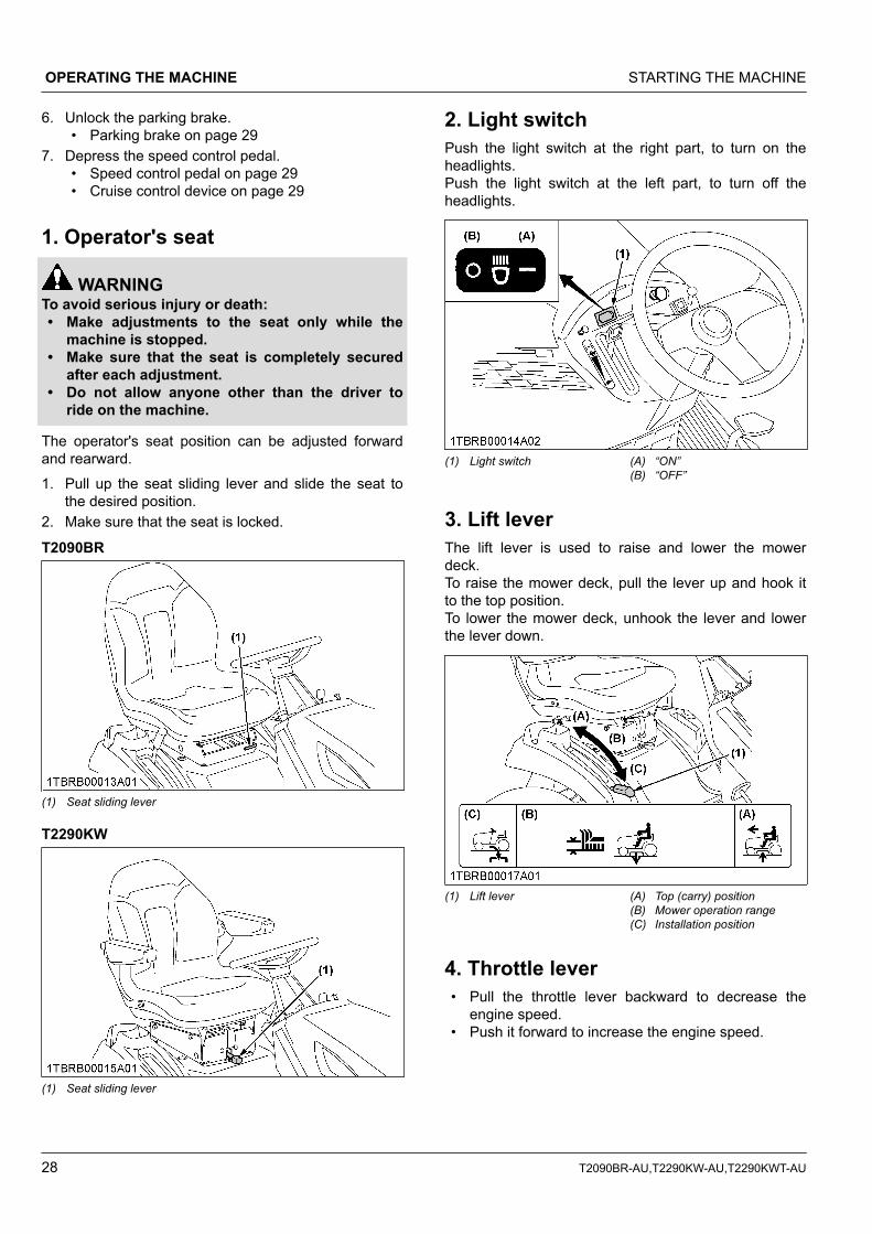
2. Light switchPush the light switch at the right part, to turn on theheadlights.Push the light switch at the left part, to turn off theheadlights.
(1) Light switch (A) “ON”(B) “OFF”
3. Lift leverThe lift lever is used to raise and lower the mowerdeck.To raise the mower deck, pull the lever up and hook itto the top position.To lower the mower deck, unhook the lever and lowerthe lever down.
(1) Lift lever (A) Top (carry) position(B) Mower operation range(C) Installation position
4. Throttle lever• Pull the throttle lever backward to decrease the
engine speed.• Push it forward to increase the engine speed.
OPERATING THE MACHINE STARTING THE MACHINE
28 T2090BR-AU,T2290KW-AU,T2290KWT-AU
(1) Throttle lever (A) “FAST”(B) “SLOW”
5. Parking brake1. To release the parking brake, depress the brake
pedal again.
(1) Brake pedal (A) “DEPRESS”
6. Speed control pedal
WARNINGTo avoid serious injury or death:• Do not operate if the machine moves on a level
ground with foot off speed control pedal.
“FORWARD”( )Depress the speed control pedal with the toe ofyour right foot to move forward.
“REARWARD”( )Depress the speed control pedal with the toe ofyour right foot to move in reverse.
Depress the speed control pedal a little and you candrive slowly.To increase travel-speed, depress the speed controlpedal more until the desired speed is reached.
NOTE :• When the parking brake is applied, the speed
control pedal is locked in the “NEUTRAL”position.
(1) Speed control pedal (A) “FORWARD”(B) “REARWARD”
7. Cruise control deviceThe cruise control device is designed for machineoperating efficiency and operator's comfort. This devicewill provide a constant forward operating speed bymechanically holding the speed control pedal at aselected position.To engage cruise control device1. Accelerate speed to desired level using speed
control pedal.2. Push the cruise control knob.
(1) Cruise control knob (A) “PUSH”
3. Release the speed control pedal while pushing thecruise control knob.
4. Release the cruise control knob and desired speedwill be maintained.
To disengage speed set device• Step on the forward acceleration side of the speed
control pedal or depress the brake pedal.
STARTING THE MACHINE OPERATING THE MACHINE
T2090BR-AU,T2290KW-AU,T2290KWT-AU 29
NOTE :• Cruise control device will not operate in
reverse.
IMPORTANT :• To prevent the damage of cruise control device,
do not depress the reverse pedal when thecruise control device is engaged.
(1) Speed control pedal (A) “FORWARD”(B) “REARWARD”
STOPPING THE MACHINE1. Release the speed control pedal and depress the
brake pedal to stop the machine.2. Push the PTO switch to the “DISENGAGED”
position.3. Slow the engine down.
CHECK DURING DRIVINGIMPORTANT :Immediately stop the engine if:• The engine suddenly slows down or
accelerates.• Unusual noises suddenly occur.• Exhaust fumes suddenly become discolored.
While driving, make the following checks to see that allthe parts are functioning normally:
1. Hour meterThe hour meter indicates in 5 digits the hours themachine has been used; the last digit indicates 1/10 ofan hour.
NOTE :• As the hour meter works electrically, it starts to
work when the key switch is turned to “ON”,regardless of the engine running or not.
(1) Hour meter
PARKING THE MACHINE
WARNINGTo avoid serious injury or death:Before leaving the operator's position:• Apply the parking brake.• Lower all implements to the ground.• Shut off the engine.• Remove the key.
When parking, be sure to set the parking brake.To apply the parking brake:1. Depress the brake pedal firmly.2. Pull the parking brake lock knob.3. Release the brake pedal while holding the parking
brake lock knob.4. Before getting off the machine, disengage the PTO,
lower all implements to the ground, set the parkingbrake, stop the engine and remove the key.
5. If it is necessary to park on an incline, be sure tochock the wheels on the downhill side to preventaccidental rolling of the machine.
(1) Chock
OPERATING THE MACHINE STOPPING THE MACHINE
30 T2090BR-AU,T2290KW-AU,T2290KWT-AU
TRANSPORTING THE MACHINE1. Transport the machine on a trailer.
• Fasten the machine to the trailer.• To prevent the hood from opening by wind while
in transit, it is necessary to either load themachine forward or use a suitable tie down forthe hood.
2. Do not attempt to tow this machine, or damage tothe transmission may result.
1. Hydrostatic transaxle bypass rodIMPORTANT :• Do not push the machine without pulling the
bypass rod or transmission damage may occur.• Never pull the rod with the engine running.
1. To push the machine, pull the HST bypass rod andhook it.
2. After moving the machine, release the rod and it willreturn automatically to normal position.
(1) HST bypass rod
TRANSPORTING THE MACHINE OPERATING THE MACHINE
T2090BR-AU,T2290KW-AU,T2290KWT-AU 31
OPERATING THE MOWERMOWING TIPS
WARNINGTo avoid serious injury or death:• Clear the work area of objects which might be
picked up and thrown by the blades.• Keep bystanders and animals away from the
mowing area.• Be sure to disengage the PTO and sit on the
operator's seat before starting the engine.
1. When using the mower for the first time, choose asmooth level area and cut in straight and slightlyoverlapping strips.
2. The size and type of the area to be mowed willdetermine the proper mowing pattern. Take intoaccount obstructions, such as trees, fences andbuildings.To keep grass clippings off fences, sidewalks andso on, it is advisable to go over the outside of thearea to be mowed several times in a clockwisedirection.To mow the area remaining, work in acounterclockwise direction so that the clippings aredispersed onto the previously cut area.
3. Always keep the left side of the mower towardtrees, posts or other obstacles on the first triparound the obstacle.
4. Most lawns must be mowed to keep the grassapproximately 50 to 80 mm (2 to 3 in.) high. Bestresults are obtained by cutting often and not tooshort.For a healthy lawn, only 1/3 of the grass plantshould be removed in one mowing. For example,tall grass with the height of 75 mm (3 in.) can be cutto a minimum of 50 mm (2 in.).
For extremely tall grass, set the cutting height atmaximum cutting height for the first mowing, thenreset to the desired height and mow again. Allowthe grass to grow to 80 mm (3 in.), then cut off onlythe top 25 mm (1 in.).
5. Clippings may be left on the lawn unless they formclumps or rows.
(A) H/G>2/3(G) Before mowing(H) Best cut grass height: 50 to 80 mm
6. For best appearance, grass must be cut in theafternoon or evening when it is free of moisture.
ADJUSTING THE CUTTINGHEIGHT
DANGERTo avoid serious injury or death:• Do not operate mower in the “TOP” position.
1. Cutting height control dialCutting height control dial can adjust the cutting heightfrom 25 mm (1 in.) to 102 mm (4 in.) with 6 mm(0.25 in.) step.
OPERATING THE MOWER MOWING TIPS
32 T2090BR-AU,T2290KW-AU,T2290KWT-AU
(1) Cutting height control dial(2) Lift lever
(A) “RAISE”(B) “LOWER”
1. Before adjusting the cutting height, check that alltire pressures are correct. If necessary, adjust tothe correct tire pressure.
2. To set the cutting height, pull the mower lift lever upto raise the mower deck to the “TOP” position.
3. Turn the cutting height control dial to adjust theheight.
4. • Use higher settings for mowing in a rough areaor when mowing tall grass.
• Use lower settings only for smooth lawns whereshort grass is desired.
5. Lower the mower deck by gently pushing themower lift lever down. This lowers the mower deckfrom the “TOP” position to the “OPERATING”position.
6. Adjust the anti-scalp rollers' height asrecommended below for normal operatingcondition.
IMPORTANT :• Never allow roller to contact the ground
continuously as premature roller wear maydevelop if set incorrectly.
• Anti-scalp rollers must maintain a minimumclearance of 6 mm (1/4in.) to the ground.
RCK42P
(1) Anti-scalp roller
RCK48P
(1) Anti-scalp roller
OPERATING THE MOWER
DANGERTo avoid serious injury or death:• Do not operate the mower without the discharge
chute being in place properly.
NOTE :• This machine is equipped with the KRA
(KUBOTA reverse awareness) system. Thisfeature shuts down the engine if the operatorattempts reverse travel while any PTO drivenimplement is engaged. The purpose of the KRAsystem is to increase operator awareness of therisk of back-over accidents.
• The KRA system incorporates an overrideswitch on the panel that allows the operator tooverride the system and keep the PTO engagedduring reverse travel.KUBOTA strongly recommends againstoverriding the KRA system, but if the operatorthinks it absolutely necessary and safe to doso, he may activate the override switch.
OPERATING THE MOWER OPERATING THE MOWER
T2090BR-AU,T2290KW-AU,T2290KWT-AU 33
The override switch light flashes while activatedas a reminder to the operator that the PTO (i.e.mower, grass catcher, snowblower, etc.)remains engaged during reverse travel. Theoperator should return the KRA system tonormal operating mode as soon as possible bymomentarily disengaging the PTO.
1. KRA system normal operatingmode1. Start the engine.2. Set the throttle lever to the “FAST” position.
(1) Throttle lever (A) “FAST” position(B) “SLOW” position
3. Pull up the PTO switch to the “ENGAGED” position.
2. PTO switch1. To engage the PTO, pull the PTO switch to the
“ENGAGED” (ON) position.2. To disengage the PTO, push the PTO switch
running, the engine will stop automatically(operator presence control).
• Before starting the engine, push the PTOswitch to the “DISENGAGED” (OFF)position. If it is at the “ENGAGED” (ON)position, the engine will not start.
• These interlock features are built-in.
3. KRA system override mode
WARNINGTo avoid serious injury or death:• Before and when backing, look down and
behind the machine to be sure no bystanders,especially children, have entered the area.
• Engine components can get extremely hot fromoperation. To prevent severe burns, do nottouch these areas while the engine is running,or immediately after it is turned off.
• Never operate the engine with heat shields orguards removed.
NOTE :• KRA system override switch allows the operator
to mow or operate attachments while in reverseif the operator deems it absolutely necessaryand safe to do so. (i.e. the operator shouldmake sure that no bystanders, especiallychildren, have entered the area.)If the owner does not wish certain operators toutilize the override switch allowing mowing orimplement operation in reverse, then he or shemay remove the fuse from the system toprevent override. (See NOTE (4) below.)
1. Start the engine.2. Set the throttle to the “FAST” position.3. Pull the PTO switch to the “ENGAGED” position.4. Stop the machine (Set the speed control pedal to
“NEUTRAL”.) or depress the speed control pedalforward.
OPERATING THE MOWER OPERATING THE MOWER
34 T2090BR-AU,T2290KW-AU,T2290KWT-AU
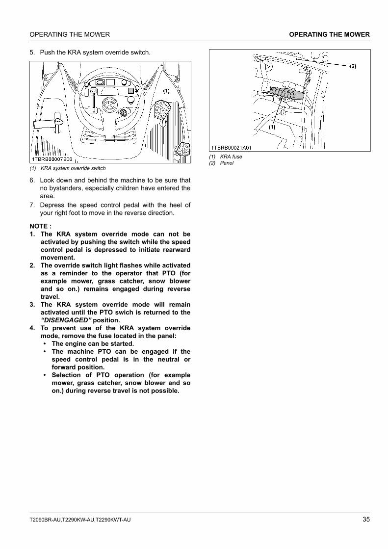
5. Push the KRA system override switch.
(1) KRA system override switch
6. Look down and behind the machine to be sure thatno bystanders, especially children have entered thearea.
7. Depress the speed control pedal with the heel ofyour right foot to move in the reverse direction.
NOTE :1. The KRA system override mode can not be
activated by pushing the switch while the speedcontrol pedal is depressed to initiate rearwardmovement.
2. The override switch light flashes while activatedas a reminder to the operator that PTO (forexample mower, grass catcher, snow blowerand so on.) remains engaged during reversetravel.
3. The KRA system override mode will remainactivated until the PTO swich is returned to the“DISENGAGED” position.
4. To prevent use of the KRA system overridemode, remove the fuse located in the panel:• The engine can be started.• The machine PTO can be engaged if the
speed control pedal is in the neutral orforward position.
• Selection of PTO operation (for examplemower, grass catcher, snow blower and soon.) during reverse travel is not possible.
(1) KRA fuse(2) Panel
OPERATING THE MOWER OPERATING THE MOWER
T2090BR-AU,T2290KW-AU,T2290KWT-AU 35
MAINTENANCE
SERVICE INTERVALSThe following servicing tasks should be carried out on the machine at the stated running-time intervals.T2090BR
No. ItemsIndication hour meter (Hr) Ref.
page25 50 100 150 200 250 300 350 400 450 500 550 600 After since
13 Engine valve clearance Check every 1 year 61*3*5
14 Fuel lineCheck every 1 year 60 *6
Replace every 4years 61 *3
15 Fuse ReplaceService asrequired
61
16 Light bulb Replace 61
17 Mower blade Check 61(Continued)
MAINTENANCE SERVICE INTERVALS
36 T2090BR-AU,T2290KW-AU,T2290KWT-AU
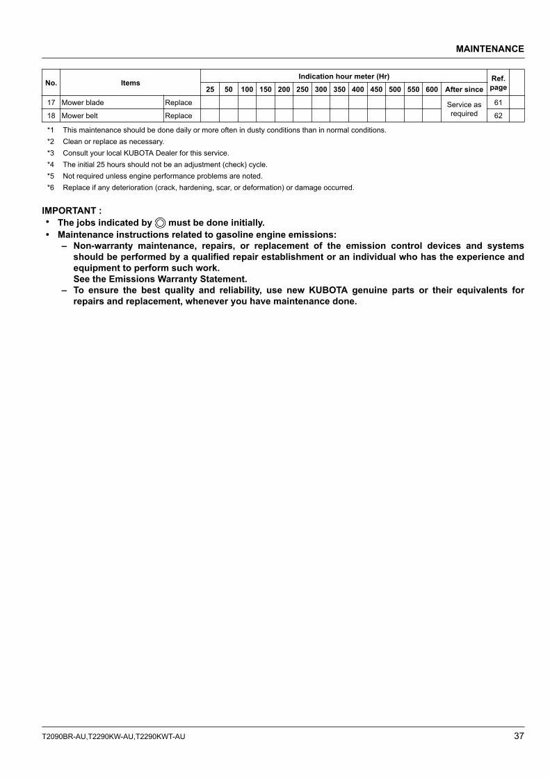
No. ItemsIndication hour meter (Hr) Ref.
page25 50 100 150 200 250 300 350 400 450 500 550 600 After since17 Mower blade Replace Service as
required61
18 Mower belt Replace 62
*1 This maintenance should be done daily or more often in dusty conditions than in normal conditions.*2 Clean or replace as necessary.*3 Consult your local KUBOTA Dealer for this service.*4 The initial 25 hours should not be an adjustment (check) cycle.*5 Not required unless engine performance problems are noted.*6 Replace if any deterioration (crack, hardening, scar, or deformation) or damage occurred.
IMPORTANT :• The jobs indicated by must be done initially.• Maintenance instructions related to gasoline engine emissions:
– Non-warranty maintenance, repairs, or replacement of the emission control devices and systemsshould be performed by a qualified repair establishment or an individual who has the experience andequipment to perform such work.See the Emissions Warranty Statement.
– To ensure the best quality and reliability, use new KUBOTA genuine parts or their equivalents forrepairs and replacement, whenever you have maintenance done.
MAINTENANCE
T2090BR-AU,T2290KW-AU,T2290KWT-AU 37
T2290KW, T2290KWT
No. ItemsIndication hour meter (Hr) Ref.
page8 25 50 100 150 200 250 300 350 400 450 500 550 600 After since
13 Valve seats and clearanceClean ● ● every 300Hr 58 *2
Adjust ● ● every 300Hr 58 *2
14 Electric clutch Adjust ● every 500Hr 58
15 Transaxle fluid (T2290KWT) Change ● every 600Hr 60
16 Transaxle oil filter(T2290KWT) Replace ● every 600Hr 59
17 Fuel lineCheck every 1 year 60 *4
Replace every 4years 61 *2
18 Engine valve clearance Check every 1 year 61*2*5
19 Fuse Replace
Service asrequired
61
20 Light bulb Replace 61
21 Mower bladeCheck
61Replace
22 Mower belt Replace 62
*1 This maintenance should be done daily or more often in dusty conditions than in normal conditions. Replace as necessary.*2 Consult your local KUBOTA Dealer for this service.*3 The initial 8 and 25 hours should not be a change (check) cycle.*4 Replace if any deterioration (crack, hardening, scar, or deformation) or damage occurred.*5 Not required unless engine performance problems are noted.
IMPORTANT :• The jobs indicated by must be done initially.• Maintenance instructions related to gasoline engine emissions:
– Non-warranty maintenance, repairs, or replacement of the emission control devices and systemsshould be performed by a qualified repair establishment or an individual who has the experience andequipment to perform such work.See the Emissions Warranty Statement.
MAINTENANCE
38 T2090BR-AU,T2290KW-AU,T2290KWT-AU
– To ensure the best quality and reliability, use new KUBOTA genuine parts or their equivalents forrepairs and replacement, whenever you have maintenance done.
MAINTENANCE
T2090BR-AU,T2290KW-AU,T2290KWT-AU 39
LUBRICANTS AND FUEL
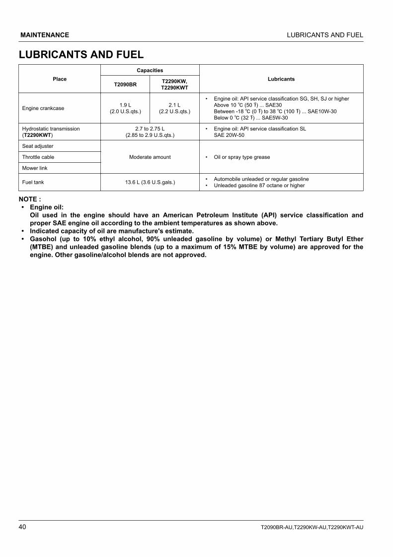
PlaceCapacities
LubricantsT2090BR T2290KW,
T2290KWT
Engine crankcase 1.9 L(2.0 U.S.qts.)
2.1 L(2.2 U.S.qts.)
• Engine oil: API service classification SG, SH, SJ or higherAbove 10 ℃ (50 ℉) ... SAE30Between -18 ℃ (0 ℉) to 38 ℃ (100 ℉) ... SAE10W-30Below 0 ℃ (32 ℉) ... SAE5W-30
Hydrostatic transmission(T2290KWT)
2.7 to 2.75 L(2.85 to 2.9 U.S.qts.)
• Engine oil: API service classification SLSAE 20W-50
Seat adjuster
Moderate amount • Oil or spray type greaseThrottle cable
Mower link
Fuel tank 13.6 L (3.6 U.S.gals.) • Automobile unleaded or regular gasoline• Unleaded gasoline 87 octane or higher
NOTE :• Engine oil:
Oil used in the engine should have an American Petroleum Institute (API) service classification andproper SAE engine oil according to the ambient temperatures as shown above.
• Indicated capacity of oil are manufacture's estimate.• Gasohol (up to 10% ethyl alcohol, 90% unleaded gasoline by volume) or Methyl Tertiary Butyl Ether
(MTBE) and unleaded gasoline blends (up to a maximum of 15% MTBE by volume) are approved for theengine. Other gasoline/alcohol blends are not approved.
MAINTENANCE LUBRICANTS AND FUEL
40 T2090BR-AU,T2290KW-AU,T2290KWT-AU
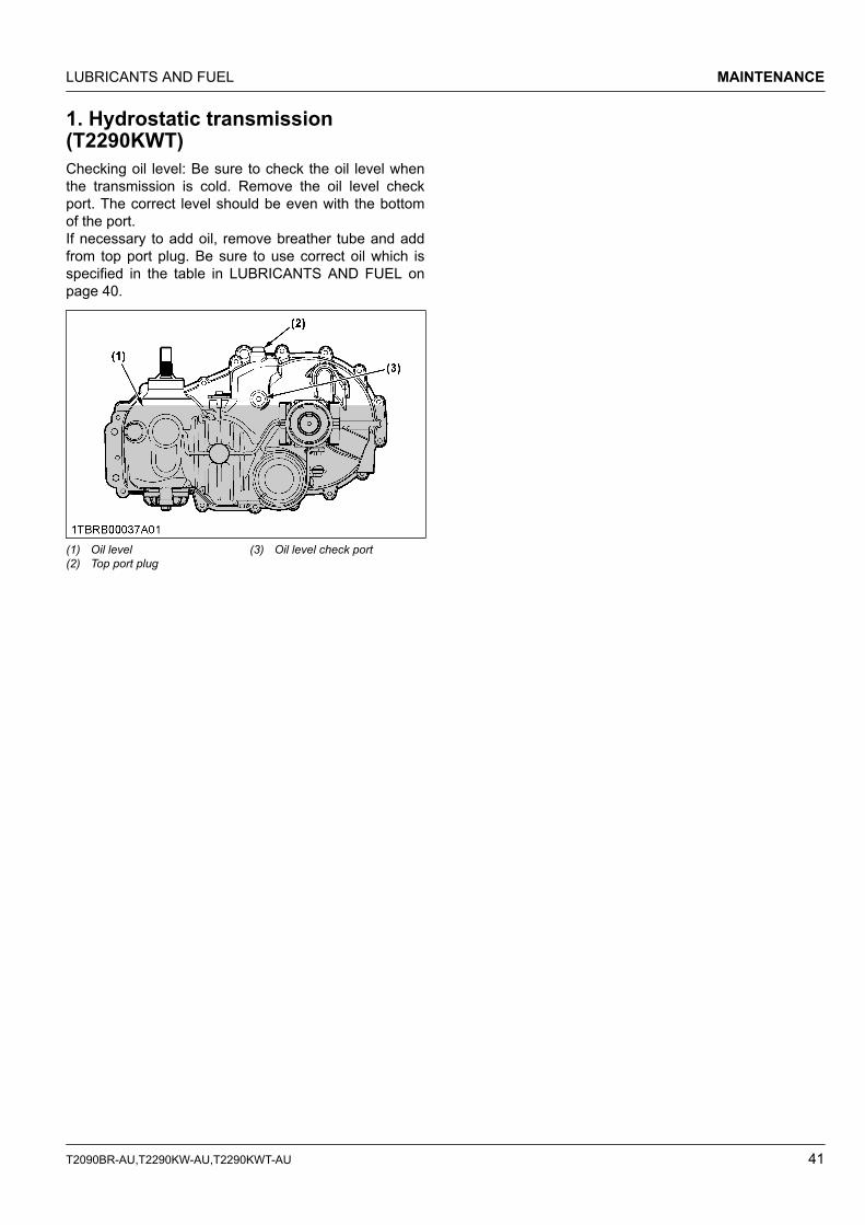
1. Hydrostatic transmission(T2290KWT)Checking oil level: Be sure to check the oil level whenthe transmission is cold. Remove the oil level checkport. The correct level should be even with the bottomof the port.If necessary to add oil, remove breather tube and addfrom top port plug. Be sure to use correct oil which isspecified in the table in LUBRICANTS AND FUEL onpage 40.
(1) Oil level(2) Top port plug
(3) Oil level check port
LUBRICANTS AND FUEL MAINTENANCE
T2090BR-AU,T2290KW-AU,T2290KWT-AU 41
PERIODIC SERVICEOPEN THE HOOD
WARNINGTo avoid serious injury or death from contact withmoving parts:• Never open the hood while the engine is
running.• Do not touch muffler or exhaust pipes while
they are hot; Severe burns could result.
1. Hood1. To open the hood, lift the hood.
(1) Hood (A) “PULL”
2. Engine cover1. Open the hood, loosen the knob bolts, remove the
harness clamp and then pull engine cover forwardto remove.
DAILY CHECKTo prevent trouble from occurring, it is important toknow the condition of the machine. Check it beforestarting.
WARNINGTo avoid serious injury or death:• Be sure to check and service the machine on a
level surface with the engine shut off, the keyremoved and the parking brake securely set.
No. Check item Ref.page
Walking aroundthe machine 1 Tire pressure, wear and
damage 47
2 Fuel and oil leak43,54,60
3 Engine oil level 43
4 Fuel level 43
5Damage of machine body,tightness of all bolts andnuts
-
6 Cooling air intake screen 44
7 Check the air cleaner 46,55
8 Oiling 45
Mower 1 Make sure blade bolts aretight. 61
(Continued)
PERIODIC SERVICE OPEN THE HOOD
42 T2090BR-AU,T2290KW-AU,T2290KWT-AU
No. Check item Ref.page
Mower 2 Check blades for wear ordamage. 61
3 Check all hardware. -
4 Make sure all pins are inplace. 21
While sitting inthe operator'sseat
1 Speed control pedalBrake pedal
29,47
2 Parking brake 47
Turning the keyswitch “ON” 1 Headlights 61
Starting the en-gine
1 Color of the exhaust fumes 70
2
Engine start system, OPCsystem, PTO control sys-tem. If either of these do notoperate properly, contactyour local KUBOTA Dealerimmediately.
24,25,25
3 Check for abnormal noiseand vibration. -
Others1
Check the areas where pre-vious trouble was experi-enced.
-
1. Checking the engine oil level
WARNINGTo avoid serious injury or death:• Always stop the engine and remove the key
before checking the oil.
Oil level check1. Check engine oil before starting the engine or 5
minutes or more after the engine has stopped.2. Wipe dipstick area clean.3. To check the oil level.
T2290KW, T2290KWTRemove the dipstick, wipe it clean, replace it anddraw it out again. Check to see that the oil level isbetween the 2 marks.
(1) Engine oil port(2) Oil level dipstick
(A) “UPPER LEVEL”(B) “LOWER LEVEL”
T2090BRRemove the dipstick, wipe it clean, replace it, anddraw it out again. Check to see that the oil level isbetween the 2 marks.
(1) Engine oil port(2) Oil level dipstick
(A) “UPPER LEVEL”(B) “LOWER LEVEL”
4. Add new oil to the prescribed level at the oil port ifnecessary.
IMPORTANT :• When using a different brand or viscosity oil
from the previous one, remove all of the oldoil. Never mix 2 different types of oil.
• Use the proper SAE engine oil according tothe ambient temperature.(See LUBRICANTS AND FUEL on page 40.)
2. Checking the amount of fuel andrefueling
WARNINGTo avoid serious injury or death:• Handle the fuel carefully. If the engine is
running, do not fill the fuel tank. If the engine ishot, let the engine cool down several minutesbefore adding fuel.
DAILY CHECK PERIODIC SERVICE
T2090BR-AU,T2290KW-AU,T2290KWT-AU 43
• Never use fire.• Do not smoke while filling the fuel tank or
servicing the fuel system. Fill fuel tank only tobottom of filler neck. Do not fill completely full.The empty space in the tank allows gasoline toexpand, when it heats up. Never remove the fueltank cap or add fuel when the fuel tank is hot.
• Be sure to close the fuel tank cap afterrefueling.
Check the fuel level. Take care that the fuel tank doesnot become empty. When refueling it, park the machineon a level surface.
Fuel tank capacity 13.6 L (3.6 U.S.gals.)
IMPORTANT :• Do not mix oil with gasoline.
Unleaded fuel is recommended. Regular leadedgasoline with an octane rating index of 87 orhigher may be used. Avoid switching fromunleaded to regular gasoline to prevent enginedamage.
NOTE :• Use fuel within approximately 30 days after
purchase to avoid deterioration in fuel quality,or add fuel stabilizer to keep fuel fresh andstabilized.
• Fuel blend differs from season to season for thebest seasonal engine performance. To preventengine performance troubles such as vaporlock or hard starting, use fuel within the seasonin which the fuel is purchased.
• Infrequent use of the engine during a seasoncan make fuel stale in the fuel tank of themachine. Stale fuel condition can cause engineperformance troubles by varnish and pluggedcarburetor components.
• Seal the fuel storage container tightly and storeit out of sunlight and heat to prevent fueldegradation.
• Condensation in the fuel tank may occurbecause of various operating or environmental
conditions. To reduce condensation and toavoid affecting machine operation, fill the fueltank at the end of daily operation.
IMPORTANT :• Do not use stale fuel.• Fill fuel tank at the end of daily operation to
prevent condensation in the fuel tank.
Gasoline/Alcohol blendsGasohol (up to 10% ethyl alcohol, 90% unleadedgasoline by volume) is approved as a fuel. Othergasoline/alcohol blends including E20 and E85 are notto be used and any failures resulting from use of thesefuels will not be warranted.Gasoline/Ether blendsMethyl Tertiary Butyl Ether (MTBE) and unleadedgasoline blends (up to a maximum of 15% MTBE byvolume) are approved as a fuel. Other gasoline/etherblends are not approved.
(1) Fuel tank cap(2) Fuel tank filler neck(3) Empty space(4) Max. fuel level
(C) Clearance(Fuel level is under the fillerneck.)
3. Checking cooling air intakescreen
WARNINGTo avoid serious injury or death:• Be sure to stop the engine before checking or
cleaning air intake screens.
IMPORTANT :• Air intake screens must be clear of debris to
prevent engine from overheating.
1. Lift hood and check that the pedestal and air intakescreens are clear of grass clippings and debris.
2. If screens are dirty, clean screens with a brush orcloth.
PERIODIC SERVICE DAILY CHECK
44 T2090BR-AU,T2290KW-AU,T2290KWT-AU
3. If the dust or chaff is accumulated inside of thepanel, clean the inside of the panel completely.After cleaning, place the air intake screen properly.
T2090BR
(1) Screen
T2290KW, T2290KWT
(1) Screen
4. Oiling
WARNINGTo avoid serious injury or death:• Be sure to stop the engine and remove the key
before oiling.
Oil the following points before starting.Oil the ends of outer wires.
T2090BR
(1) Throttle cable
T2290KW, T2290KWT
(1) Throttle cable
T2290KW, T2290KWT
(1) Seat slider
DAILY CHECK PERIODIC SERVICE
T2090BR-AU,T2290KW-AU,T2290KWT-AU 45
T2090BR
(1) Seat slider
RH
(1) Pivot of lift arm(2) Around the pin(3) Pivot of mower link
LH
(1) Around the pin(2) Pivot of mower link
NOTE :• Oil these points on both sides of the machine.
EVERY 25 HOURS1. Cleaning air cleanerT2090BR
Check the air cleaner daily or before starting theengine. Check for a buildup of dirt and debris aroundthe air cleaner system. Keep this area clean. Alsocheck for loose or damaged components. Replace allbent or damaged air cleaner components.
IMPORTANT :• Operating the engine with loose or damaged air
cleaner components could allow unfiltered airinto the engine causing premature wear andfailure.
Clean precleanerWash and reoil the precleaner every 25 hours ofoperation. (more often under extremely dusty or dirtyconditions.)1. Loosen the air cleaner cover knobs and remove the
air cleaner cover.
(1) Air cleaner cover knob(2) Air cleaner cover
(A) “LOOSEN”
2. Remove air cleaner element as an assembly forservicing, remove precleaner from the air cleanerelement. Make sure the base and the sealing areais clean before reassembly is performed.
(1) Precleaner(2) Air cleaner element
(B) Base
3. Wash the precleaner in warm water with detergent.Rinse the precleaner thoroughly until all traces ofdetergent are eliminated. Squeeze out excesswater. (do not wring.) Allow the precleaner to air dry.
PERIODIC SERVICE EVERY 25 HOURS
46 T2090BR-AU,T2290KW-AU,T2290KWT-AU
4. Reinstall the precleaner over the paper element andinstall the assembly on the base.
5. Reinstall the air cleaner cover and secure it with 2knobs.
NOTE :• Operating in dusty condition may require
more frequent maintenance than above.
EVERY 50 HOURS1. Checking brake pedal
WARNINGTo avoid serious injury or death:• When making adjustments, park the machine on
a flat area, block wheels, stop engine andremove the key.
1. Check the length of brake spring when the parkingbrake is applied. Correct length ranges from 28 to29 mm (1.1 in.).
2. If it is not correct, loosen the lock nut (1) and turnthe nut (2) in the desired direction until the properplay is achieved.
3. After adjustment, retighten lock nut securely.
(1) Lock nut(2) Nut(3) Spring
(A) Length 28 to 29 mm (1.1 in.)
2. Checking the tire pressure
WARNINGTo avoid serious injury or death:• Do not attempt to mount a tire on a rim. This
should be done by a qualified person with theproper equipment.
• Always maintain the correct tire pressure.Do not inflate the tires above the recommendedpressure shown in the operator's manual.
IMPORTANT :• Do not use tires larger than specified.
2.1 Inflation pressureThough the inflation pressure is factory-set to theprescribed level, it naturally drops slowly in the courseof time. Thus, check it and inflate as necessary.
IMPORTANT :• When jacking up the rear tires, be sure
1. To block the front tires.2. To position a jack inside beside either of the
supporting plates.
EVERY 100 HOURS1. Changing engine oil
WARNINGTo avoid serious injury or death:• Be sure to stop the engine and remove the key
before changing the oil.• Allow the engine to cool down sufficiently. Oil
can be hot and may cause burns.
T2090BREvery 100 hours of operation or annually change theengine oil.1. To change the used oil, unhook the drain hose,
direct the hose down and open the drain valve.The used oil can be drained out more easily if theengine is warm.
EVERY 50 HOURS PERIODIC SERVICE
T2090BR-AU,T2290KW-AU,T2290KWT-AU 47
(1) Drain hose(2) Drain valve(3) Hook
2. Close the drain valve. Put back the drain hose. Fillwith the new oil up to the upper level on thedipstick. Do not overfill.
(1) Engine oil port(2) Oil level dipstick
(A) “UPPER LEVEL”(B) “LOWER LEVEL”
3. To check the oil level. Remove the dipstick, wipe itclean, insert it and draw it out again. Check to seethat the oil level is between the 2 marks.
NOTE :• Do not overfill.
T2290KW, T2290KWTAfter the first 8 hours, change the engine oil.1. Insert the hose attached with the machine to the T-
type pipe fitting on the right side of the engine.In the case of no hose attached, use the hydraulichose of inner diameter 0.5 in., length about 6 in.Direct the hose down, loosen the nut of the T-typepipe fitting and drain the engine oil. Tighten the nut.
NOTE :• The used oil can be drained out more easily
if the engine is warm.
(1) T-type pipe fitting(2) Nut(3) Hose
(A) Engine(B) Screw driver(C) Ground
2. Fill with the new oil up to the upper level on thedipstick.
(1) Engine oil port(2) Oil level dipstick
(A) “UPPER LEVEL”(B) “LOWER LEVEL”
3. To check the oil level. Remove the dipstick, wipe itclean, insert it and draw it out again. Check to seethat the oil level is between the 2 marks.
NOTE :• Do not overfill
PERIODIC SERVICE EVERY 100 HOURS
48 T2090BR-AU,T2290KW-AU,T2290KWT-AU
2. Replacing engine oil filter(T2090BR)
WARNINGTo avoid serious injury or death:• Engine oil is a toxic substance. Dispose of used
oil properly. Contact your local authorities forapproved disposal methods or possiblerecycling.
• Be sure to stop the engine and remove the keybefore changing the oil and the oil filtercartridge.
• Allow engine to cool down sufficiently; oil canbe hot and may cause burns.
The oil filter cartridge must be changed every 100service hours or annually.Always use a genuine oil filter.T2090BR1. To change the used oil, unhook the drain hose,
direct the hose down and open the drain valve. Theused oil can be drained out more easily if theengine is warm.
2. Remove the old filter and wipe off the filter adapterwith a clean cloth.
3. Place a new replacement filter in a shallow pan withthe open end up. Pour new oil of the proper type, inthrough the threaded center hole. Stop pouringwhen the oil reaches the bottom of the threads.Allow a minute or 2 for the oil to be absorbed by thefilter material.
4. Apply a thin film of clean oil to the rubber gasket onthe new filter.
5. Install the replacement oil filter to the mounting pad.Turn the oil filter clockwise until the rubber gasketcontacts the pad, then tighten the filter an additional1/2 to 3/4 turn.
(1) Engine oil filter cartridge
6. Fill the crankcase, with new oil of the proper type,to the upper level on the dipstick. SeeLUBRICANTS AND FUEL on page 40.
Always check the level with the dipstick beforeadding more oil.
7. Reinstall the oil fill cap/dipstick and push firmly intoplace.
8. Test run the engine to check for leaks. Stop theengine, allow a minute for the oil to drain down, andrecheck the level on the dipstick. Add more oil, asnecessary, so the oil level is up to but not over theupper level on the dipstick.
NOTE :• To prevent extensive engine wear or damage,
always maintain the proper oil level in thecrankcase. Never operate the engine with the oillevel below the lower level or over the upperlevel on the dipstick.
3. Cleaning engine shroud
WARNINGTo avoid serious injury or death:• Make sure engine is cool to the touch before
removing shrouds.• Always shield eyes and face from air deposits
and objects.
1. Remove the engine shroud mounting bolts anddetach the shroud.
EVERY 100 HOURS PERIODIC SERVICE
T2090BR-AU,T2290KW-AU,T2290KWT-AU 49
2. Check to see if the engine's cooling fins are blockedwith dust and dirt. Clean them with compressed airif required.
T2090BR
(1) Shroud
T2290KW, T2290KWT
(1) Shroud
4. Checking spark plugEvery 100 hours of operation check the spark plugcondition and gap.1. Lift hood and remove the engine cover.2. Remove the spark plug wire from spark plug.3. Use a spark plug wrench to remove plug.
T2290KW, T2290KWT
(1) Spark plug (both sides)
T2090BR
(1) Spark plug
4. Inspect spark plug for cracked porcelain, pittedelectrodes, or other wear and damage. Replacespark plug if necessary.
PERIODIC SERVICE EVERY 100 HOURS
50 T2090BR-AU,T2290KW-AU,T2290KWT-AU
5. Check spark plug gap with gap gauge.
Recommendedspark plug
T2090BR CHAMPIONXC12YC
T2290KW,T2290KWT NGK BPR4ES
NOTE :• This engine is equipped with resistor-type
spark plug.
(A) 0.76 mm (0.03 in.)
5. Adjusting throttle cable (T2090BR)1. Move the throttle lever to the “FAST” position.
(1) Throttle lever (A) “FAST”(B) “SLOW”(C) “CHOKE”
2. Attempt to pass a pin (A) with a diameter of 3 mmthrough the holes indicated.
(1) Bolt(2) Throttle lever cable sheath
(A) Pin with a diameter of 3 mm(B) Hole(P) “CHOKE”
3. If not possible, loosen the bolt (1) and pull thethrottle lever cable sheath (2) in the direction of thearrow so that the pin (A) passes through all therequired holes (B). And then tighten the bolt (1).
6. Adjusting throttle cable(T2290KW, T2290KWT)1. Move the throttle lever to the “FAST” position.
(1) Throttle lever (A) “FAST”(B) “SLOW”
2. Link the throttle cable (1) to the speed control lever(2) and loosely clamp the throttle cable sheath (3)with the cable clamp bolt (A).
3. Pull up the sheath (3) of the throttle cable until theinner wire of throttle cable has almost no slack, andtighten the cable clamp bolt (A).
EVERY 100 HOURS PERIODIC SERVICE
T2090BR-AU,T2290KW-AU,T2290KWT-AU 51
4. Move the throttle lever to “SLOW” position. Makesure that the carburetor throttle valve is movedsmoothly.
(1) Throttle cable(2) Speed control lever(3) Throttle cable sheath
(A) Throttle cable clamp bolt
7. Adjusting choke cable (T2290KW,T2290KWT)1. Move the choke knob to the “OFF” position.
2. Link the choke cable (1) to the choke control lever(2), and loosely clamp the choke cable sheath (3)with the cable clamp bolt (A). Make sure that thecarburetor choke valve is fully opened.
3. Pull up the sheath (3) of the choke cable until theinner wire of choke cable has almost no slack, andtighten the cable clamp bolt (A).
4. Move the choke knob to the “ON” position. Makesure that the carburetor choke valve is completelyclosed.
5. Make sure that the choke valve turns from fullyclosed position to fully opened position whenactuating the equipment choke knob.
(1) Choke cable(2) Choke control lever(3) Choke cable sheath
(A) Choke cable clamp bolt
8. Checking the battery condition
DANGERTo avoid the possibility of battery explosion:For the refillable type battery, follow theseinstructions:• Do not use or charge the refillable type battery
if the fluid level is below the [LOWER] (lowerlimit level) mark. Otherwise, the batterycomponent parts may prematurely deteriorate,which may shorten the battery's service life orcause an explosion.
• Check the fluid level regularly and add distilledwater as required so that the fluid level isbetween the [UPPER] and [LOWER] levels.
• When the battery is being activated, hydrogenand oxygen gases in the battery are extremelyexplosive. Keep open sparks and flames awayfrom the battery at all times, especially whencharging the battery.
WARNINGTo avoid serious injury or death:• Batteries, battery posts, terminals and related
accessories contain lead, lead compounds andother chemicals known to the State of Californiato cause cancer and birth defects or otherreproductive harm. Wash hands after handling.
• Never remove the battery cap while the engineis running.
• Keep electrolyte away from eyes, hands andclothes. If you are spattered with electrolyte,wash it away completely with water immediatelyand get medical attention.
• Keep open sparks and flames away from thebattery at all times. Hydrogen gas mixed withoxygen becomes very explosive.
• Wear eye protection and rubber gloves whenworking around the battery.
PERIODIC SERVICE EVERY 100 HOURS
52 T2090BR-AU,T2290KW-AU,T2290KWT-AU
NOTE :• The factory-installed battery is a non-refillable
type.If the battery is weak, charge the battery orreplace it with a new one.
IMPORTANT :• Mishandling the battery shortens the service life
and adds to maintenance costs.The original battery is maintenance free, butneeds some servicing.If the battery is weak, the engine will be difficultto start and the lights will be dim. It is importantto check the battery periodically.
• When exchanging an old battery with a newone, use a battery of equal specifications (asdescribed in the following table).
Batterytype Volts (V)
Capacity20 HR(Ah)
Coldcranking
amps
Normalchargingrate (A)
U1-300 12 45 300 6.5
Regarding non-accessible maintenance-free typebatteries:Maintenance-free, non-accessible batteries aredesigned to eliminate the need to add water. Yet thevolume of electrolyte above the plates may eventuallybecome depleted due to abnormal conditions such ashigh heat or improper regulator settings. Use avoltmeter to check the state of charge.(See the following reference chart to determine ifcharging is necessary.)
Battery voltage Reference state of charge
12.6 100% (full charge)
12.4 75%
12.2 50%
12.0 25%
11.8 0%
8.1 Charging the battery
DANGERTo avoid serious injury or death:• When the battery is being activated, hydrogen
and oxygen gases in the battery are extremelyexplosive. Keep open sparks and flames awayfrom the battery at all times, especially whencharging the battery.
WARNINGTo avoid serious injury or death:
• When disconnecting the cable from the battery,start with the negative terminal first. Whenconnecting the cable to the battery, start withthe positive terminal first.
• Never check the battery charge by placing ametal object across the posts.Use a voltmeter or hydrometer.
(1) Battery(2) Ground cable
(+) Positive terminal(-) Negative terminal
1. To slow charge the battery, connect the batterypositive terminal to the charger positive terminaland the negative to the negative. Then, charge forat least 1 hour at 6 to 10 amperes.
2. A boost charge is only for emergencies. It willpartially charge the battery at a high rate and in ashort time. When using a boost-charged battery, it isnecessary to recharge the battery as early aspossible. Failure to do this will shorten the battery'sservice life.
3. When the specific gravity of electrolyte is between1.27 and 1.29, the charging is completed.
8.2 Storing the battery1. When storing the machine for a long period, remove
the battery from machine, adjust the electrolyte tothe proper level and store in a dry place out ofdirect sunlight.
2. The battery self-discharges while it is stored.Recharge it once a month in hot seasons and onceevery 2 months in cold seasons.
9. Replacing air cleaner paperelementT2090BREvery 100 hours of operation or annually replace thepaper element if equipped with a precleaner. Checkevery 25 hours of operation or annually if not equippedwith a precleaner.(More often under extremely dusty or dirty conditions.)
EVERY 100 HOURS PERIODIC SERVICE
T2090BR-AU,T2290KW-AU,T2290KWT-AU 53
1. Loosen the air cleaner cover knobs and remove theair cleaner cover.
(1) Air cleaner cover knob(2) Air cleaner cover
(A) “LOOSEN”
2. Remove air cleaner element with precleaner.3. Remove the precleaner from the paper element.
(1) Precleaner(2) Air cleaner element(B) Base
4. Gently tap the paper element to remove dirt. Do notwash the paper element or use pressurized air, asthis will damage the element. Replace a dirty, bent,or damaged element with a genuine part. Handlethe new element carefully; do not use if the sealingsurfaces are bent or damaged.
5. Clean the air cleaner base as required and checkcondition.
6. Reinstall the precleaner over the paper air cleanerelement and install it on the base.
7. Reinstall the air cleaner cover and secure with the 2knobs.
10. Checking fuel filter
WARNINGTo avoid serious injury or death:• Be sure to stop the engine and remove the key
when attempting to make the following checksand changes.
• Never fail to check the fuel lines periodically.The fuel lines are subject to wear and aging.Fuel may leak out onto the running engine,causing a fire.
The fuel line is made of rubber and ages regardless ofservice period.
PERIODIC SERVICE EVERY 100 HOURS
54 T2090BR-AU,T2290KW-AU,T2290KWT-AU
1. If the fuel line, fuel filter and clamps are founddamaged or deteriorated, replace them.
IMPORTANT :• When the fuel line is disconnected for
maintenance or repair, close both ends ofthe fuel line with a piece of clean cloth orpaper to prevent dust and dirt from entering.In addition, particular care must be taken notto admit dust and dirt into the fuel pump.Entrance of dust and dirt causesmalfunction of the fuel pump.
11. Cleaning air cleaner paperelement (T2290KW, T2290KWT)Every 100 hours of operation or annually replace thepaper element.Check the air cleaner daily or before starting theengine. Check for a buildup of dirt and debris aroundthe air cleaner system. Keep this area clean. Alsocheck for loose or damaged components. Replace allbent or damaged air cleaner components.
EVERY 100 HOURS PERIODIC SERVICE
T2090BR-AU,T2290KW-AU,T2290KWT-AU 55
1. Lift up the tabs to open the air cleaner cover.
(1) Air cleaner cover (A) “LIFT UP”
2. Remove the air cleaner paper element and the airintake hose.
(1) Air cleaner cover(2) Air cleaner paper element
(A) Air intake hose
3. Replace a dirty, bent, or damaged element with agenuine part. Handle the new element carefully; donot use if the sealing surfaces are bent ordamaged.
(1) Air cleaner paper element (A) Air intake hose
4. Clean the air cleaner base as required and checkcondition.
(B) Air cleaner base
5. Install the air cleaner paper element into the airintake hose, and reinstall them in place.
6. Close the air cleaner cover.
NOTE :• Operating the engine with loose or damaged
air cleaner components could allowunfiltered air into the engine causingpremature wear and failure.
EVERY 200 HOURS1. Replacing air cleaner paperelementT2290KW, T2290KWTEvery 200 hours of operation or annually replace thepaper element.1. Lift up the tabs to open the air cleaner cover.
(1) Air cleaner cover (A) “LIFT UP”
2. Remove the air cleaner paper element and the airintake hose.
PERIODIC SERVICE EVERY 200 HOURS
56 T2090BR-AU,T2290KW-AU,T2290KWT-AU
(1) Air cleaner cover(2) Air cleaner paper element
(A) Air intake hose
3. Replace a dirty, bent, or damaged element with agenuine part. Handle the new element carefully; donot use if the sealing surfaces are bent ordamaged.
(1) Air cleaner paper element (A) Air intake hose
4. Clean the air cleaner base as required and checkcondition.
(B) Air cleaner base
5. Install the air cleaner paper element into the airintake hose, and reinstall them in place.
6. Close the air cleaner cover.
NOTE :• Operating the engine with loose or damaged
air cleaner components could allowunfiltered air into the engine causingpremature wear and failure.
2. Replacing engine oil filter
WARNINGTo avoid serious injury or death:• Engine oil is a toxic substance. Dispose of used
oil properly. Contact your local authorities forapproved disposal methods or possiblerecycling.
• Be sure to stop the engine and remove the keybefore changing the oil and the oil filtercartridge.
• Allow engine to cool down sufficiently; oil canbe hot and may cause burns.
The oil filter cartridge must be changed every 200service hours.Always use a genuine oil filter.T2290KW, T2290KWT1. Insert the hose attached with the machine to the T-
type pipe fitting on the oil filter side of the engine.In the case of no hose attached, use the hydraulichose of inner diameter 0.5 in., length about150 mm.Direct the hose down, loosen the nut of the T-typepipe fitting and drain the engine oil. Tighten the nut.
2. Remove the old filter and wipe off the filter adapterwith a clean cloth. After draining the oil, return thenut of the t-type pipe fitting to its original position.
3. Place a new replacement filter in a shallow pan withthe open end up. Pour new oil, of the proper type,in through the threaded center hole. Stop pouringwhen the oil reaches the bottom of the threads.Allow a minute or 2 for the oil to be absorbed by thefilter material.
4. Apply a thin film of clean oil to the rubber gasket onthe new oil filter.
5. Install the new oil filter to the filter adapter. Handtighten the filter clockwise until the rubber gasketcontacts the adapter, then tighten the filter anadditional 3/4-1 turn.
6. Fill the engine with the proper oil to the upper levelon the dipstick. Always check the oil level with thedipstick before adding more oil.
7. Reinstall the oil fill cap/dipstick and tighten securely.8. Start the engine and check for oil leaks. Recheck oil
level before placing the engine into service.Stop the engine, correct any leaks, and allow aminute for the oil to drain down, then recheck thelevel on the dipstick.
EVERY 200 HOURS PERIODIC SERVICE
T2090BR-AU,T2290KW-AU,T2290KWT-AU 57
NOTE :• To prevent extensive engine wear or damage,
always maintain the proper oil level in thecrankcase. Never operate the engine with the oillevel below the lower level or above the upperlevel on the dipstick.
EVERY 300 HOURS1. Cleaning combustion chamber(T2290KW, T2290KWT)If you do not have the proper tools and/or are notmechanically proficient, consult your local KUBOTADealer for this service.
2. Checking engine valve seats andclearanceConsult your local KUBOTA Dealer for this service.
EVERY 500 HOURS1. Adjusting the electric clutchThe electric clutch serves 2 functions in the operationof the mower:• Starting and stopping the power flow to the cutter
blades.• The clutch also acts as a brake to assist in stopping
blade rotation when the PTO is switched off or theoperator presence control is interrupted.
When the clutch is disengaged, the air gap between thearmature and rotor must be adjusted to 0.4 mm(0.015 in.) for proper operation. The air gap adjustmentis made with 3 bolts on the clutch. There are 3inspection windows, one next to each adjusting bolt.
(1) Inspection window (x3) (A) Electric clutch
1. Locate the inspection windows on the clutch.2. Place a 0.4 mm (0.015 in.) feeler gauge in the slot
between the rotor and the armature.
(A) Electric clutch(P) “INSERT 0.4 mm (0.015 in.) FEELER GAUGE HERE”
PERIODIC SERVICE EVERY 300 HOURS
58 T2090BR-AU,T2290KW-AU,T2290KWT-AU
3. Tighten or loosen the adjusting nut as needed toachieve the 0.4 mm (0.015 in.) air gap. Perform thisoperation at all 3 inspection windows.
(A) Electric clutch(Q) Adjustment nut
This adjustment should be done every 500 hours ofoperation or annually, whichever comes first. Incase the machine is heavily used, air gap settingsshould be checked more often.If the air gap is too narrow, the clutch armature maydrag when disengaged, resulting in prematurefailure.
2. Cleaning combustion chamber(T2090BR)If you do not have the proper tools and/or are notmechanically proficient, consult your local KUBOTADealer for this service.
EVERY 600 HOURS1. Replacing transaxle filter(T2290KWT)
WARNINGTo avoid serious injury or death:• Park the machine on a firm and level surface.• Apply the parking brake.• Be sure to stop the engine and remove the key
before changing or checking the oil.• Allow the transmission case to cool down
sufficiently, as oil can be hot and may causeburns.
1. Apply the bypass valve.2. Remove the hex head bolts (4), and filter guard (3).
Clean any loose debris from around the perimeterof the oil filter (2).
3. Place an oil drain pan (12" or more diameter and 8qt. capacity is optimal) beneath the oil filter.Remove the oil filter (2) and discard it.
NOTE :• Always replace the filter when preforming
any internal maintenance to the transaxle.
4. After the oil has drained, inspect all parts forexcessive wear or damage. Replace if necessary.
5. Wipe the filter base surface off and apply a film ofnew oil to the gasket of the new replacement filter(Hydro-gear part number 52114).
6. Install the new filter by hand, turn 3/4 to 1 full turnafter the filter gasket contacts the filter basesurface.
Left side view of transaxle
(1) Transaxle(2) Transaxle oil filter(3) Filter guard(4) Hex flange head bolt(5) Metal fitting assembly(6) Barbed cap(7) Hose(8) Oil level check port plug
(A) “FRONT”(B) “OIL LEVEL”
7. Re-install the filter guard (3) with 3 hex head bolts(4). Torque bolts (4) to 7.35 N⋅m (5.42 lbf⋅ft)securely.
8. Remove the oil level check port plug (9) from thetransaxle prior to filling with oil. This will allow thetransaxle to vent during oil fill.
9. Remove the hose (7), the barbed cap (6) and themetal fitting assembly (5).
EVERY 500 HOURS PERIODIC SERVICE
T2090BR-AU,T2290KW-AU,T2290KWT-AU 59
10. Fill with 20W50 motor oil until oil just appears at thebottom of the oil level check port. Install the oil levelcheck port plug (9) into transaxle. Torque the plug(9) to 20.34 N⋅m (15.0 lbf⋅ft).
11. Install the metal fitting assembly (5) to the transaxle(1) and torque the metal fitting assembly (5) to20.34 N⋅m (15.0 lbf⋅ft). Then install the barbed cap(6) and the hose (7).
12. Proceed to the purge procedure.
2. Changing transaxle fluid(See Replacing transaxle filter (T2290KWT) on page59.)
EVERY 1 YEAR1. Checking fuel line
WARNINGTo avoid serious injury or death:• Be sure to stop the engine and remove the key
when attempting to make the following checksand changes.
• Never fail to check the fuel lines periodically.The fuel lines are subject to wear and aging.Fuel may leak out onto the running engine,causing a fire.
The fuel line is made of rubber and ages regardless ofservice period.1. If the fuel line and clamps are found damaged or
deteriorated, replace them.
IMPORTANT :• When the fuel line is disconnected for
maintenance or repair, close both ends ofthe fuel line with a piece of clean cloth orpaper to prevent dust and dirt from entering.In addition, particular care must be taken notto admit dust and dirt into the fuel pump.Entrance of dust and dirt causesmalfunction of the fuel pump.
2. Replacing spark plug(See Checking spark plug on page 50.)
3. Checking engine valve clearanceConsult your local KUBOTA Dealer for this service.
EVERY 4 YEARS1. Replacing fuel linesThis should be done by your local KUBOTA Dealer.
SERVICE AS REQUIRED1. Replacing fuses1. Open the hood.2. Remove the blown fuse.3. Place a new 3 A or 10 A fuse in position.
(1) Fuse location(2) Slow blow fuse(3) Battery
IMPORTANT :• If the new fuse happens to blow out within a
short time, contact your dealer for inspectionand repair. Never “jump” the fuse with wire orfoil, etc.
Protected circuitFuse number
(id label) Capacity (A) Protected circuit
(1) START 10
(2) KRA 3 KRA system
(3) OPC 3 Engine running circuit
(4) PTO 10
(5) ACC 3
(6) (extrafuse) 3
(7) Slowblow fuse 30 Check circuit against wrong
battery connection
2. Replacing bulbsReplacement of the headlight bulb1. Open the hood.2. Turn bulb socket to remove socket from headlight
housing.3. Push bulb down and turn 1 quarter turn to remove
bulb from the socket.4. Install new bulb to the socket.5. Install the socket in housing.6. Close the hood.
Headlight LED bulb 12.8 rated voltage/0.1 AMP/7.96 MSCP
3. Checking and replacing blades
WARNINGTo avoid serious injury or death:• Be sure to stop the engine and remove the key.• Blades may be sharp. When you handle blades,
wear heavy gloves or wrap the end of theblades with a rag.
NOTE :• Before checking or replacing the blades, wipe
grass and mud off the top and inside of themower.Especially, clean up inside the belt cover,because otherwise the belt life will be reduced.
CheckingThe blade cutting edges should be kept sharp at alltimes.
EVERY 1 YEAR PERIODIC SERVICE
T2090BR-AU,T2290KW-AU,T2290KWT-AU 61
1. Sharpen the cutting edges if they look like blade(B).
2. Replace the blades if they look like blade (C).
(A) New blade(B) Worn blade(C) Cracked blade
Replacing1. Dismount the mower deck from the machine.
(See DISMOUNTING THE MOWER DECK on page21.)Then turn it over to expose the blades.
2. Wedge a block of wood between the blade andmower housing or use a box wrench over the pulleynut to prevent the spindle from rotating whileremoving the blade bolts; loosen the blade bolt asillustrated.
IMPORTANT :• Use the proper metric size box or socket
wrench to tighten or loosen the blademounting bolt.
(1) Block (A) “LOOSEN”
3. To sharpen the blades yourself, clamp the bladesecurely in a vise.Use a large mill file and file along the original beveluntil sharp.
4. To check the blade for balance, place a small rodthrough the center hole. If the blade is notbalanced, file the heavy side of the blade untilbalance is achieved.
5. To attach blades, be sure to install the cup washerbetween the blade and bolt head. Then tighten thebolt securely.
(1) Spindle holder(2) Blade(3) Cup washer(4) Bolt
IMPORTANT :• Tighten the blade bolts from 103 to 118 N⋅m
(76 to 87 lbf⋅ft) of torque.• The blade bolts have Right hand threads.
Turn them counterclockwise to loosen.• To prolong the service life of the blades,
reposition them as shown in the figurebelow periodically. RCK42P also.
(1) LH blade(2) Center blade(3) RH blade
4. Replacing the mower belt
WARNINGTo avoid serious injury or death:• Be sure to reinstall the removed cover after
replacing the belt.
PERIODIC SERVICE SERVICE AS REQUIRED
62 T2090BR-AU,T2290KW-AU,T2290KWT-AU
1. Remove the mower deck from the machine.(See DISMOUNTING THE MOWER DECK on page21.)
2. Remove the left and right hand shield from themower deck.
3. Remove the belt.4. To install a new belt, reverse the above procedure.
RCK42P
(1) Tension pulley(2) Belt(3) Bolt(4) Shield
RCK48P
(1) Tension pulley(2) Belt(3) Bolt(4) Shield
NOTE :• The mower belt must be outside of the guard
pin.
(1) Engine pulley(2) Mower belt
(3) Guard pin
SERVICE AS REQUIRED PERIODIC SERVICE
T2090BR-AU,T2290KW-AU,T2290KWT-AU 63
ADJUSTMENTMOWER DECK LEVEL1. Anti-scalp rollers
WARNINGTo avoid serious injury or death:• Park the machine on a firm and level surface.• Apply the parking brake.• Stop the engine and remove the key.• Wait for all moving parts to stop.
NOTE :• The flattest cut can be achieved by having the
anti-scalp rollers adjusted off the ground.Check the anti-scalp roller adjustments eachtime the mower deck cutting height is changed.It is recommended that all the anti-scalp rollersbe kept off the ground to minimize scuffing.
1. Check the machine tire pressure.Inflate tires to the correct pressure.(See Checking the tire pressure on page 47.)
2. Start the engine.3. Raise up the mower deck to the top position (the
top end of the lift).4. Turn the cutting height control dial to adjust the
height.5. Lower the mower deck.6. Adjust the height of the front side anti-scalp roller to
1 of the 4 positions, to approximately 19 mm(0.75 in.) between the rollers and the ground.Adjust the other 3 rollers to the same height.
(1) Front side anti-scalp roller (H) 19 mm (0.75 in.)
7. Attach hardware.
2. Leveling the mower deck (side-to-side)
WARNINGTo avoid serious injury or death:• Park the machine on a firm and level surface.• Apply the parking brake.• Disengage the PTO (OFF).• Stop the engine and remove the key while
checking or adjusting the level of the mowerdeck.
IMPORTANT :• Check the machine tire pressure.
Inflate the tires to the correct pressure.(See Checking the tire pressure on page 47.)
Checking the level (side-to-side)
NOTE :• The mower deck anti-scalp rollers should not
contact the ground.
1. Raise the mower deck to the top position (the topend).
2. Turn the cutting height set dial to the 3 in. cuttingheight position.
3. Lower the mower deck.4. Position the right mower blade in the side-to-side
position.5. Measure from outside the blade tip to the level
surface with a short ruler or leveling gauge.
ReferenceHeight of the blade at the flat surface 76 mm (3 in.)
NOTE :• There is a difference of blade height
between flat surface and groundmeasurements.
6. Check that the left side blade has the same height.The difference between both measurements is lessthan 3 mm (0.13 in.).
7. If the side-to-side adjustment is not within the giventolerance, adjustment is necessary.
Side-to-side adjustment Less than 3 mm(0.13 in.)
ADJUSTMENT MOWER DECK LEVEL
64 T2090BR-AU,T2290KW-AU,T2290KWT-AU
(S) Side
Adjusting the level (side-to-side)1. Raise up the mower deck to the top position (the
top end).2. Turn the cutting height set dial to the 3 in. cutting
height position.3. Place 51 mm (2 in.) height wood blocks under each
side of the mower deck.Anti-scalp rollers must not rest on the wood block.
4. Lower the mower deck.5. Position the mower blade in the side-to-side
position.6. Loosen the jam nuts of the right side of the
machine.7. Adjust the cutting height fine tuning bolts to set
76 mm (3 in.) blade height.Front and rear side bolts must be adjusted.
8. Jam the nuts.9. Adjust the left side equally.10. Check the side-to-side level. If it is not level,
adjustment is necessary.
(1) Cutting height fine tuning bolt(2) Jam nut(3) 51 mm (2 in.) height wood blocks
3. Leveling the mower deck (front-to-rear)
WARNINGTo avoid serious injury or death:• Park the machine on a firm and level surface.• Engage the parking brake.• Disengage the PTO.• Stop the engine and remove the key while
checking or adjusting the level of the mowerdeck.
IMPORTANT :• Check the machine tire pressure.
Inflate the tires to the correct pressure.(See Checking the tire pressure on page 47.)
Checking the level (front-to-rear)
NOTE :• The mower deck anti-scalp rollers should not
contact the ground.
1. Raise the mower deck to the top position (the topend).
2. Turn the cutting height set dial to the 3 in. cuttingheight position.
3. Lower the mower deck.4. Position the right mower blade in the front-to-rear
position.5. Measure from the right front blade tip to the level
surface with a short ruler or leveling gauge.6. Turn the blade 180° and measure from the right
rear blade tip to the level surface.7. Check that the left side blade has the same
dimensions. The difference between bothmeasurements should be less than 6 mm (0.25 in.).The front side must be lower than the rear side.
8. If the front-to-rear adjustment is not within the giventolerance, adjustment is necessary.
(A) Front(B) Rear
MOWER DECK LEVEL ADJUSTMENT
T2090BR-AU,T2290KW-AU,T2290KWT-AU 65
Front-to-rear adjustmentLess than 6 mm (0.25 in.)
The front side must be lower than therear side.
Adjusting the level (front-to-rear)1. Raise up the mower deck to the top position (the
top end).2. Turn the cutting height set dial to the 3 in. cutting
height position.3. Place 51 mm (2 in.) height wood blocks under each
side of the mower deck.Anti-scalp rollers must not rest on the wood block.
4. Lower the mower deck.5. Loosen the jam nuts of the front side of the
machine.6. Adjust the cutting height fine tuning bolts to set
76 mm (3 in.) blade height.Both front side bolts must be adjusted.
7. Jam the nuts.8. Adjust the other side equally.
IMPORTANT :• The difference between both measurements
should be less than 6 mm (0.25 in.).The front side must be lower than the rearside.
9. Check the front-to-rear level. If it is not level,adjustment is necessary.
(1) Cutting height fine tuning bolt(2) Jam nut(3) 51 mm (2 in.) height wood blocks
ADJUSTMENT MOWER DECK LEVEL
66 T2090BR-AU,T2290KW-AU,T2290KWT-AU
GENERAL TORQUE SPECIFICATIONAmerican standard cap screws with UNC or UNF threads Metric cap screws
SAE grade no.GR.5 GR.8
Property classClass 8.8 Class 10.9
1/4(lbf⋅ft)(N⋅m)
(kgf⋅m)
8-9.610.7-12.91.11-1.33
12-14.416.1-19.31.66-1.99
M6(lbf⋅ft)(N⋅m)
(kgf⋅m)
7.2-8.39.81-11.31.0-1.15
5/16(lbf⋅ft)(N⋅m)
(kgf⋅m)
17-20.523.1-27.82.35-2.84
24-2932.5-39.33.31-4.01
M8(lbf⋅ft)(N⋅m)
(kgf⋅m)
17.4-20.223.6-27.42.4-2.8
21.7-25.329.4-34.33.0-3.5
3/8(lbf⋅ft)(N⋅m)
(kgf⋅m)
35-4247.5-57.04.84-5.82
45-5461.0-73.26.22-7.47
M10(lbf⋅ft)(N⋅m)
(kgf⋅m)
35.5-41.248.1-55.84.9-5.7
44.9-52.160.8-70.56.2-7.2
1/2(lbf⋅ft)(N⋅m)
(kgf⋅m)
80-96108.5-130.211.07-13.29
110-132149.2-179.015.22-18.27
M12(lbf⋅ft)(N⋅m)
(kgf⋅m)
57.2-66.577.5-90.17.9-9.2
76.0-86.8103-117
10.5-12.0
9/16(lbf⋅ft)(N⋅m)
(kgf⋅m)
110-132149.2-179.015.22-18.27
160-192217.0-260.422.14-26.57
M14(lbf⋅ft)(N⋅m)
(kgf⋅m)
91.2-108124-14712.6-15.0
123-144167-19617.0-20.0
5/8(lbf⋅ft)(N⋅m)
(kgf⋅m)
150-180203.4-244.120.75-24.91
220-264298.3-358.030.44-36.53
M16(lbf⋅ft)(N⋅m)
(kgf⋅m)
145-166196-22520.0-23.0
192-224260-30326.5-31.0
GENERAL TORQUE SPECIFICATION ADJUSTMENT
T2090BR-AU,T2290KW-AU,T2290KWT-AU 67
TIGHTENING TORQUE CHARTThread size d
(mm)Hex. bolt head
size B (mm)No mark 7T
lbf⋅ft N⋅m kgf⋅m lbf⋅ft N⋅m kgf⋅m
M8 12 or 13 13.0-15.2(14.1 ± 1.1)
17.8-20.6(19.2 ± 1.4)
1.9-2.1(2.0 ± 0.1)
17.5-20.3(18.9 ± 1.4)
23.5-27.5(25.5 ± 2.0)
2.4-2.8(2.6 ± 0.2)
M10 14 or 17 28.9-33.3(31.1 ± 2.2)
39.3-45.1(42.2 ± 2.9)
4.0-4.6(4.3 ± 0.3)
35.4-41.2(38.3 ± 2.9)
48.1-55.9(52.0 ± 3.9)
4.9-5.7(5.3 ± 0.4)
M12 17 or 19 46.3-53.5(49.9 ± 3.6)
62.8-72.6(67.7 ± 4.9)
6.4-7.4(6.9 ± 0.5)
57.1-66.5(61.8 ± 4.7)
77.6-90.2(83.9 ± 6.3)
8.0-9.2(8.6 ± 0.6)
M14 19 or 22 79.6-92.6(86.1 ± 6.5)
107.9-125.5(116.7 ± 8.8)
11.0-12.8(11.9 ± 0.9)
91.1-108.5(99.8 ± 8.7)
123.6-147.0(135.3 ± 11.7)
12.6-15.0(13.8 ± 1.2)
NOTE :• Figure [7] on the top of the bolt indicates that the bolt is made of special material.• Before tightening, check the figure on top of the bolt.
(1) Scale
ADJUSTMENT TIGHTENING TORQUE CHART
68 T2090BR-AU,T2290KW-AU,T2290KWT-AU
STORAGE
WARNINGTo avoid serious injury or death:• To reduce fire hazards, allow the engine and
exhaust system to cool before storing themachine in an enclosed space or nearcombustible materials.
• To avoid the danger of exhaust fume poisoning,do not operate the engine in a closed buildingwithout proper ventilation.
• Do not clean the machine with the enginerunning.
• To avoid fire hazards, do not leave grass andleaves in the mower and the grass catcher.
• When storing, remove the key to avoidunauthorized persons from operating themachine and getting injured.
STORING THE MACHINEWhen the machine will not be operated for over 2months, clean the machine and perform the followingoperations before storage.1. Repair parts as necessary.2. Check bolts and nuts and tighten as necessary.3. Apply grease or engine oil to parts most likely to
rust.4. Inflate the tires to a little above the standard
pressure levels. (Approximately 110%)5. Lower the mower to the ground.6. Remove the battery from the machine, recharge it,
adjust the electrolyte to the proper level, and storein a cool dry place.The battery discharges over time even while instorage. Recharge it once a month in hot seasonsand once every 2 months in cold seasons.
7. Drain fuel tank, fuel lines, and carburetor, or use afuel stabilizer, to prevent deterioration of thegasoline. If you choose to use a fuel stabilizer,follow the manufacturers recommendations, andadd the correct amount for the capacity of the fuelsystem. Fill the fuel tank with clean, fresh gasoline.Run the engine for 2 to 3 minutes to get stabilizedfuel into the carburetor.
8. Store the machine where it is dry and shelteredfrom rain. Cover the machine with a tarpaulin.
9. Moisture content in most grasses can damage themower and grass catcher if these components arenot properly cleaned after use. Make sure the
mower and the grass catcher are clean andcompletely empty before storage.
REMOVING THE MOWER FROMSTORAGE1. Check the tire inflation pressure and adjust as
required.2. Install the battery. Before installing the battery,
make sure it is fully charged.3. Do daily checking.
(See DAILY CHECK on page 42.)4. Check all fluid levels. (engine oil, hydrostatic oil)5. Start the engine. Shut the engine off and walk
around the machine and make a visual inspectionlooking for evidence of oil or other fluids.
6. Run engine a couple of minutes before you putengine under load.
7. With the engine fully warmed up, release theparking brake and test the brakes for properadjustment as you move forward. Adjust the brakesas necessary.
STORING THE MACHINE STORAGE
T2090BR-AU,T2290KW-AU,T2290KWT-AU 69
TROUBLESHOOTING
ENGINE TROUBLESHOOTINGIf the engine is not performing correctly, refer to the table below for the cause and its corrective measure.
If Check
Engine is difficult to start. • Fuel tank or fuel filter is clogged by dirt.
• Spark plug malfunction.
• Dirt or water in the fuel system.
• In winter, oil viscosity increases, and engine cranks slowly.
• Battery is discharged.
Insufficient engine power. • Air cleaner element is clogged.
• Insufficient fuel flow or quality.
Engine stops suddenly. • Insufficient fuel.
Exhaust fumes are colored. • Fuel quality is poor.
Black smoke is emitted from the muffler during operation; power out-put is lowered.
• Air cleaner element clogged.
• Choke not fully opened.
Bluish white smoke is emitted from the muffler during operation. • Too much engine oil.
Engine will not idle. • Spark plug not gapped correctly.
• Faulty spark plug.
Engine loses power or overheats. • Engine overheating.
• Dirty air cleaner.
• Dirt or water in fuel lines, filter, etc.
• Out of fuel.
• Engine cooling air intake screen or air cleaner element plugged.
Engine knocks. • Stale or low octane fuel.
If you have any questions, contact your local KUBOTA dealer.
TROUBLESHOOTING ENGINE TROUBLESHOOTING
70 T2090BR-AU,T2290KW-AU,T2290KWT-AU
BATTERY TROUBLESHOOTINGIf Check
The starter does not function. • Battery discharged.
• Poor terminal connection.
• The battery life has expired.
When viewed from the top, the top of the plates look whitish. • Electrolyte level is low.
• The battery was used too much without recharging.
Recharging is impossible. • The battery life has expired.
Terminals are severely corroded and heated up. • Poor terminal connection or stained terminal.
The battery electrolyte level drops rapidly. • There is a crack or pin holes in the electrolytic cells.
• Charging system trouble.
If you have any questions, contact your local KUBOTA dealer.
MACHINE TROUBLESHOOTINGIf Check
The machine operation is not smooth. • The hydrostatic transmission oil is low.
The machine does not move while the engine is running. • The parking brake is on.
• Transmission oil is insufficient.
• HST belt slipping or broken.
Machine moves when speed control pedal is not depressed. (Engineis operated.)
• Hydrostatic neutral system is not correctly adjusted.
If you have any questions, contact your local KUBOTA dealer.
BATTERY TROUBLESHOOTING TROUBLESHOOTING
T2090BR-AU,T2290KW-AU,T2290KWT-AU 71
MOWER TROUBLESHOOTINGIf Check
Discharge chute plugged. • Grass too wet.
• Grass too long.
• Cutting too low.
• Engine rpm too low.
• Ground speed too fast.
Streaking of grass uncut. • Ground speed too fast.
• Engine rpm too low.
• Grass too long.
• Blades dull or damaged.
• Debris in mower deck.
Uneven cut. • Mower deck not level.
• Ground speed too fast.
• Blades dull.
• Blades worn.
• Tire inflation.
• Mower rollers not adjusted correctly.
Blades scalping grass. • Cutting height too low.
• Blades speed too fast.
• Ridges in terrain.
• Rough or uneven terrain.
• Bent blade(s).
• Low tire inflation.
• Anti-scalp rollers not adjusted correctly.
Belt slipping. • Belt tension incorrect.
• Mower deck plugged.
• Debris in pulleys.
• Worn belt.
Excessive vibration. • Debris on mower deck or in pulleys.
• Damaged drive belt or mower belt twisted.
• Damaged pulleys.
• Pulleys out of alignment.
• Blades out of balance.
Mower loads down machine. • Engine rpm too low.
• Ground speed too fast.
• Debris wrapped around mower spindles.
Grass tips are jagged and turn grayish brown. • Blades dull.
• Blades worn.
• Mower deck is not level.
TROUBLESHOOTING MOWER TROUBLESHOOTING
72 T2090BR-AU,T2290KW-AU,T2290KWT-AU
If you have any questions, contact your local KUBOTA dealer.
TROUBLESHOOTING
T2090BR-AU,T2290KW-AU,T2290KWT-AU 73
INDEXAair cleaner
cleaning.................................................................46air cleaner paper element
replacing...........................................................53,56air cleaner paper element (T2290KW, T2290KWT)
cleaning.................................................................58controls........................................................................19cooling air intake screen
checking................................................................44cruise control device................................................... 29cutting height
adjusting................................................................32cutting height control dial............................................ 32
Ddaily check
checking fuel level ................................................43checking the engine oil level................................. 43checking the tire pressure.....................................47refueling................................................................ 43
Kkey switch....................................................................23KRA system normal operating mode.......................... 34KRA system override mode........................................ 34
before operating......................................................5operating on slopes.................................................7parking.................................................................. 30scrapping procedure............................................. 16servicing.............................................................8,15specification table..................................................17starting.................................................................. 27starting to operate................................................... 5stopping..............................................................7,30storing................................................................ 9,69transporting........................................................ 7,31troubleshooting......................................................71warranty................................................................ 16working....................................................................6
before operating the machine................................. 5general information................................................. 5operating on slopes.................................................7servicing the machine............................................. 8starting to operate the machine...............................5stopping the machine..............................................7storing the machine.................................................9transporting the machine.........................................7working the machine............................................... 6
safety for children..........................................................7safety for operators (age 60 years and older)............... 7safety labels................................................................ 10
taking care of the labels ....................................... 14service intervals.......................................................... 36spark plug
speed control pedal.....................................................29switches...................................................................... 19