LIFTING TEREX T750 Truck Crane FEATURES - 75 ton (68 mt) maximum lifting capacity -126 fl. (38.4 m) maximum boom length -192 fl. (58.5 m) maximum lip height • Four-section full power boom with single lever control • SWingaway jib offsettable 0°, 1yo or 30° • Two-speed main and auxiliary winches • QUick-reeving boom head and hook block • Fully independent multi-position out and down outriggers • Environmental operator's cab optimizes load visibility and productivity • Travel speeds to 55 mph (88 km/h) • Tight 42 ft. 9 in. (13 m) turning radius • Easy to read load chart books include range diagrams • 12-month or 2000 hours warranty, major weldments are 5-years or 10,000 hours simple, available and cost effective"" Machines shown may have optional equipment.
Transcript
LIFTING
TEREX
T750Truck Crane
FEATURES
- 75 ton (68 mt)maximum lifting capacity
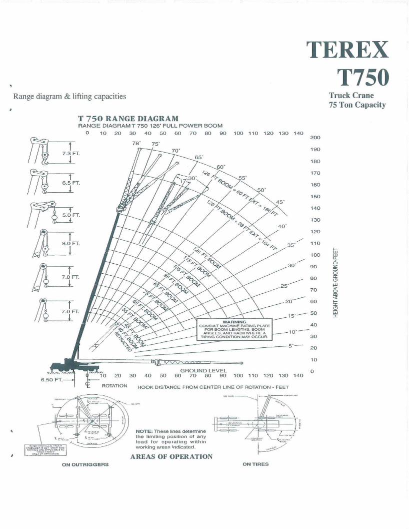
-126 fl. (38.4 m)maximum boom length
-192 fl. (58.5 m)maximum lip height
• Four-section full power boom withsingle lever control
• SWingaway jib offsettable0°, 1yo or 30°
• Two-speed main and auxiliary winches
• QUick-reeving boom head andhook block
• Fully independent multi-position outand down outriggers
• Environmental operator's cab optimizesload visibility and productivity
• Travel speeds to 55 mph (88 km/h)
• Tight 42 ft. 9 in. (13 m) turning radius
• Easy to read load chart books includerange diagrams
• 12-month or 2000 hours warranty,major weldments are 5-years or10,000 hours
simple, available andcost effective""Machines shown may have optional equipment.
TEREX T 750Truck CraneMax. Lifting Capacity: 75 tons (68 mt)
126 ft. (38.4 m)FOUR-SECTION, FULL-POWERBOOM WITH SINGLE LEVERCONTROL• High strength, four plate construction.
• Two double-acting boom hoistcylinders provide boom elevation of_2° to 78° for easier reeving changesand close radius operation.
• Quick-reeving boom head; no need toremove wedge from socket.
ENVIRONMENTALOPERATOR'S CAB - UPPER• Rated Capacity Indicator (RCI) system
including anti-two block system withautomatic function disconnects.
• Fully adjustable operator's seat hasshock-absorbing suspension andadjustable arm rests.
• Sound and weather insulated forcomfort.
• Hinged tinted skylight and slidingright-hand, rear and door windows,roof wiper.
• Armrest mounted joystick or twin levercontrols for swing, auxiliary winch,main winch and boom hoist; footcontrol pedals for swing brake, boomtelescope and engine throttle.
• Complete instrumentation.Environmentally-sealed rockerswitches. Circuit breakers in cab.
RUGGED,EASY-TO-MANEUVERCARRIER'10 ft. (3 m) wide chassis is Terex
designed and built with 8 x 4 drive.
• Full aluminum decking, fendersand rims.
• Ground level outrigger controls arebuilt into rear fenders.
'13 forward, 2 reverse RoadRangertransmission.
• Dual circuit, air self-adjusting front andrear service brakes.
• Fully independent hydraulic outriggersmay be utilized fully extended to 23 ft.7.5 in. (7.2 m), in their mid extendedposition or fully retracted positions.
• 414 HP (309 kw) Detroit DieselS60 engine.
POWERFUL, TWO-SPEEDWINCHES• 456 fpm (181 mpm) maximum line
speed, 20,400 Ibs. (9250 kg) maximumline pull. Single lever control.
• Integral automatic brake.
• Electronic drum indicators.
• Winch drum rollers.
HIGH CAPACITY, DEPENDABLEHYDRAULIC SYSTEM• Two tandem gear-type pumps driven off
front of carrier engine. Combinedsystem capability is 158 gpm(598 Ipm).
• Hydraulic reservoir with 177 gal.(615 I) capacity and full flow oilfiltration system.
OPTIONS INCLUDE:• 38 ft. or 38 to 60 ft. (11.6 or 11.6 to
18.3 m) swingaway jib. Both offset0°, 1r or 30°,
• Auxiliary winch with rope anddrum roller.
• Heater/defroster, air conditioner foroperator's cab; air conditioner forcarrier cab.
• Cold weather kit for carrier cab.
For more information, product demonstration, or details on purchase. lease and rentalplans, please contact your local Terex Cranes Distributor.
We reserve the right to amend these specifications at any time without notice. The onlywarranty applicable is our standard writlen warranty applicable to the particular productand sale, We make no other warranty, expressed or implied.
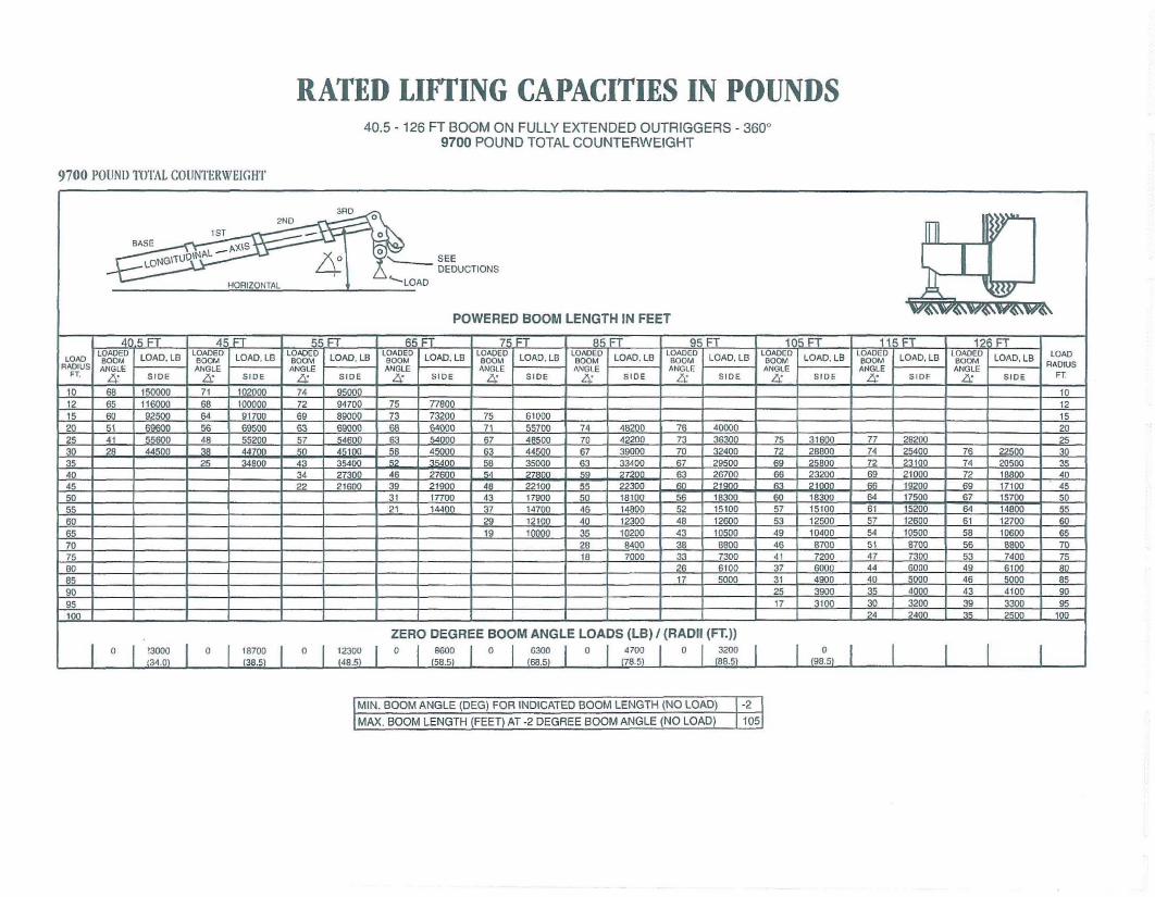
RADIUS ANGLE ANGLE ANGLE ANGLE A~E I\NGI.E ANGLF. ANGLE ANGLE ANGLE RADIUSFT. Z4: sIDe Z4: SIDE Z4: SIDE Z4: SIDE SIDE Z4: SiDE Z4: SIDE Z4: SIDE Z4: SJOF Z4: SIDE FT
I 0 I 23000 0 I 4700 I 0 I 3400 I 0 I 2500 l 0 I 0 I 0 I 0 I(34.01 (78.5) (88.5) (98.5) .. (106.5) (119.5)
MIN. BOOM ANGLE (DEG) FOR INDICATED BOOM LENGTH (NO LOAD) -2
MAX. BOOM LENGTH (FEET) AT -2 DEGREE BOOM ANGLE (NO LOAD) 126
GENERAL NOTES
2.
2.
3.
3.
8. When spin resistant wire rope is used, the allowable rope loadingshall be the breaking strength divided by 5. unless otherwisespecified by the wire rope manufacturer.
OPERATIONI. CRANE LOAD RATINGS MUST NOT BE EXCEEDED. DO NOT
ATTEMPT TO TIP THE CRANE TO DETERMINE ALLOWABLELOADS.
2. When either radius or boom length, or both, are between listed values,The smaller of the two listed load ratings shall be used.
3. Do not operate at longer radii than those listed on the applicable loadrating chart (cross hatched areas shown on range diagrams).
4. The boom angles shown on the capacity chart give an approximationof the operating radius for a specified boom length. The boom anglebefore loading, should be greater to account for boom deflection. Itmay be necessary to retract the boom if maximum boom angle isinsufficient to maintain rated radius.
5. Power telescoping boom sections must be extended equally.6. Rated loads include the weight of hook block, slings, and auxiliary lift
ing devices. T11eir weights shall be subtracted from the listed ratedload to obtain the net load that can be lifted.When lifting over the jib the weight of any hook block, slings, andauxiliary lifting devices at the boom head must be added to the load.When jibs are erected but unused add 2 times the weight of anyHook block, slings, and auxiliary lifting devices at the jib head to theloads.
7. Rated loads do not exceed 85% on outriggers or 75% on tires, of thetipping loads as determined by SAE Crane Stability Test Code J765A.Rated loads for partially extended outriggers are determined from theFormula. Rated Load=(Tipping Load - 0.1 X Tip Reaction)/ 1.25.Structural strength ratings in chart are indicated with an asterisk *.
8. Rated loads are based on freely suspended loads. No attempt shallbe made 10 drag a load horizontally on the ground in any direction.
9. The user shall operate al reduced ratings to allow for adverse jobcondilions, such as soft or uneven ground, OUI of level conditions,high winds, side loads, pendulum action, jerking or sudden Sloppingof loads, hazardous conditions, experience of personnel, two machinelifts, traveling with loads, electric wires, etc. (side pull on boom or jibis hazardous) Derating of the cranes lifting capacily is required whenwind speed exceeds 20-mph. The center of the lifted load must neverbe allowed 10 move more than 3* fl. off the center line of the baseboom section due to effects of wind, inertia. or both.**Use 2 feet off the cenler line of the base boom for a two seclionboom, 3 feet for a three section boom, or 4 feet for a four sectionboom.
10. The maximum load that can be telescoped is not definable,because of variations in loadings and crane maintenance, but it isPermissible to attempt retraction and extension if load ratings are notexceeded.
II. Load ratings are dependent upon the crane being maintained according 10 manufacturers specifications.
12. It is recommended that load handling devices, including hooks, andhook blocks, be kept away from boom had at all times.
13. FOR TRUCK ONLY: 360 deg. capacities apply only to machinesequipped wilh a front outrigger jack and all 5 outrigger jacks properlyset. If the front (5) outrigger jack is not properly set, the work area isrestricted to the over side and over rear areas as shown or :he craneWorking positions diagram. Use the 360 deg. Load ratings in theoverside work areas.
5.
4.
6.
3.
GENERALI. Rated loads as shown on lift charts pertain to this machine as origi
nally manufactured and equipped. Modifications to the machine oruse of optional equipment other than that specified can result in aReduction of capacity.Construction equipment can be hazardous if improperly operated ormaintained. Operation and maintenance of this machine shall be incompliance with the information in the Operators, Parts and SafetyManuals supplied with this machine. If these manuals are missing,Order replacements from the manufacturer thru your distributor.These warnings do not constitute all of the operating conditions forthe crane. The operator and job site supervision musl read theOPERATORS MANUAL, CIMA SAFETY MANUAL. APPLICABLEOSHA REGULATIONS, AND SOCIETY OF MECHANICALENGINEERS (ASME) SAFETY STANDARDS FOR CRANES.This crane and its load ratings are in accordance wilh POWERCRANE & SHOVEL ASSOCIATION, STANDARD NO.4 SAECRANE LOAD STABILITY TEST CODE J765A, SAE METHODOF TEST FOR CRANE STRUCTURE J1063 AND APPLICABLESAFETY CODE FOR CRANE, DERRICKS AND HOISTS,ASME/ANSI B30.5.
DEFINITIONSI. LOAD RADlUS- The horizontal distance from the axis of rotation
Before loading to the center of the vertical hoist line or tackle with aLoad applied.LOADED BOOM ANGLE- II is the angle between the boom baseSection and the horizontal, after lifting the rated load at the ratedRadius. The boom angle before loading should be greater to accountfor deflections. The loaded boom angle combined with boom lengthgive only an approximation of the operating radius.WORKING AREA- Areas measured in a circular arc about the centerline of rotation as shown in the diagram.FREELY SUSPENDED LOAD- Load hanging free with no directExternal force applied except by the hoist rope.SIDE LOAD- Horizontal force applied to the lifted load either on theground or in the air.NO LOAD STABILITY LIMIT- The stability limit radius shown on therange diagrams is the radius beyond which it is not permitted to posi-tion the boom, when the boom angle is less than the minimum shownon the applicable load chart, because the machine can overturn without any load.
SET-UPI. Crane load ratings are based on the crane being leveled and standing
on a firm, uniform supporting surface.Crane load ratings on outriggers are based on all outrigger beamsbeing fully extended or in the case of partial extension ratingsmechanically pinned in the appropriate position, and the tires free ofthe supporting surface.Crane load ratings on tires depend on appropriate inflation pressureand the tire conditions. Caution must be exercised when increasing airpressure in tires. Consult operator's manual for precautions.Use of jibs, lattice-type boom extensions, our fourth section pulloutsextended is not permitted for pick and carry operations.Consult appropriate section of the Operator's and Service manual formore exact descriptions of hoist line reeving.The use of more parts of line than required by the load may ·result inhaving insufficient rope to allow the hook block to reach the ground.Properly maintained wire rope is essential for safe crane operation.Consult Operator's Manuals for proper maintenance and inspectionrequirements.
4.
6.
2.
4.
•
,
DEDUCTIONS TO BE MADE FROM LOAD RATINGS
HOOK BLOCK WEIGHTS
9.2 Ton Ball Hook
20 Ton 1 Sheave Hook Block
75 Ton 5 Sheave Hook Block
476 Pounds
420 Pounds
1,220 Pounds
8.3 M Ton Ball Hook
18.1M Ton 1 Sheave Hook Block
68M Ton 5 Sheave Hook Block
213 Kg.
190 Kg.
443 Kg.
Note: These weights apply only to TEREX. INC supplied equipment.
The load charts for the T750 are net load charts.The deductions to these charts are:
1. The weight of hook block, slings and auxiliary lifting devices. Their weight must be subtractedfrom the listed rated lifting capacity to obtain the net load to be lifted.
2. When lifting over the lattice extension of the weight of any hook block, slings, and auxiliarylifting devices at the main boom head must be added to the load.
3. When the lattice extension is erected but unused, add three (3) times the weight of any hookblock, slings, and auxiliary lifting devices at the extension head to the load. Outriggers must bein the fully extended position when lifting at the main boom head with the lattice extensionerected.
4. Add 150 pounds to the chart values if the auxiliary boom head sheave is not erected.
5. All other deductions have been taken in the charts.
NOTE: All deSigns, SpeClllcalions, and components 01 the equipment deSCribed atcM:! aresubjeCl 10 Change allhe manufacturer's sale discretion at Bny time ano Without advancenotice. Capacily charts and information printed here afe only a glide and may nol becomple1e. They should nol be relied upon 10 operate the crane. The indiVIdual load chaMand lelaled lilting dala on each crene must be understood and govern operalion 01 thecrane. Dala publtshed herem Is lnlormalional In nature and shall not be construed 10warrant suilablilly ot the machine tor any particular purpose as perlormance may varywith conditions encountered. The only warranty applicable is oul standard warranty lorIhls machine.


![EFFICIENT-REC-C - Sécheron · EFFICIENT-REC-C / CoNTRollEd RECTIFIERs 3 CONTROLLED RECTIFIER RANGE Standard controlled rectifier range Rated dC voltage [V] 750 1500 3000 Rated current](https://static.documents.pub/doc/80x56/60008ea66503ba52224a1241/efficient-rec-c-scheron-efficient-rec-c-controlled-rectifiers-3-controlled.jpg)


