r. NTECHNICAL REPORT RD-CR-82-27 4PERSHING II SIMULATION STUDIES J. D. Knight: R. L. Lynch; D. A. Pyles; R. N. Seitz; T. V. Thornton Georgia Institute of Technology Engineering Experiment Station Atlanta, GA 30332 PREPARED FOR Systems Simulation and Development Directorate US Army Missile Laboratory D T IC ELC T EI NOV 1 t8 July 1982 B L*Pcedtc~on ArmenmI, AIatrf 35009 APPROVED FOR PUBLIC RELEASE; DISTRIBU77ON UNLIMITED Wd FORI) #01, I JUL 7 PREVIOUS EDITION 18 OBSOLETE 82 11 08 077
Transcript
r.
NTECHNICAL REPORT RD-CR-82-27
4PERSHING II SIMULATION STUDIES
J. D. Knight: R. L. Lynch; D. A. Pyles; R. N. Seitz; T. V. ThorntonGeorgia Institute of TechnologyEngineering Experiment StationAtlanta, GA 30332
PREPARED FORSystems Simulation and Development Directorate
US Army Missile Laboratory D T ICELC T EINOV 1 t8
July 1982 B
L*Pcedtc~on, ArmenmI, AIatrf 35009
APPROVED FOR PUBLIC RELEASE; DISTRIBU77ON UNLIMITED
DESTROY THIS REPORT WHEN IT IS NO LONGER NEEDED. DO NOT
RETURN IT TO THE ORIGINATOR.
DISCLAIMER
THE FINDINGS IN THIS REPORT ARE NOT TO OE CONSTRUED AS ANOFFICIAL DEPARTMENT OF THE ARMY POSITION UNLESS SO DESIG-
NATED BY OTHER AUTHORIZED DOCUMENTS.
TRADE NAMES
USE OF TRADE NAMES OR MANUFACTURERS IN THIS REPORT OES
NOT CONSTITUTE AN OFFICIAL INOORSEMENT OR APPROVAL OFTHE USE OF SUCH COMMERCIAL HARDWARE OR SOFTWARE.
P.
UNCLASSIFIEDSECURITY CLASSIFICATION OF THIS PAGE (ften Date Enter**
REPORT DOCUMENTATION PAGE BEFORE COMPLETING FORM
.- REPORT NUMBER . GOVT ACCESSION No. 3. RECIPIENT'S CATALOG NUMBER
4. TITLE (nd Subttle) S. TYPE OF REPORT & PERIOD COVERED
Final Technical Report
PERSHING II SIMULATION STUDIES 3 February - 28 May. 1982S. PERFORMING ORG. REPORT NUMBER
A-31657. AUTHOR(.) S. CONTRACT OR GRANT NUMBER(e)
J. D. Knight, R. L. Lynch, D. A. Pyles, DAAHOI-81-D-A003R. N. Seitz, and T. V. Thornton Delivery Order 0038
9. PERFORMING ORGANIZATION NAME AND ADDRESS 10. PROGRAM ELEMENT, PROJECT, TASKAREA & WORK UNIT NUMBERS
Georgia Institute of TechnologyEngineering Experiment StationAtlanta. Georgia 30332
11. CONTROLLING OFFICE NAME AND ADDRESS 12- REPORT OATS
U. S. Army Missile Command July 1982DRSMI-IYB/Koger 13. NUMBER OF PAGES
Redstone Arsen- AL 358989314. MONITORING AGENCY NAME & AOOR S I different r om Controlaind Office) IS. SECURITY CLASS. (of this report)
U. S. Army Missile Command UnclassifiedDRSMI-PDF/Hallum 0IS. DECL ASSI FI CATION/DOWNGRADINGRedstone Arsenal, AL 35898 SCHEDULE
16. DISTRIBUTION STATEMENT (of this Report)
Approved for public release, distribution unlimited
17. DISTRIBUTION STATEMENT (of the abstract antere in Block 20, ii different from Report)
IS. SUPPLEMENTARY NOTES
iS. KEY WOROS (Cattimm on #*"WOr Oid* If ne4eewM7, nd identlO by biock mnmber)
Pershing II, PIZ, U70 Simulator, White Sands Missile Range, WSMR RangeSafety, Missile Flight Validation, Aerodynamic Validation, TacticalBallistic Missile Trajectories, Maximum Likelihood Method
2& AIWRACr (0mm ,v-r a&*w. ne- -i -tlr by block n -.wba)
Pershing II flight simulations were performed using the U70 missile simulationprogram to determine (1) in the event of an accidental nozzle deflection, how
fast the missile would leave its (safe) flight corridor; (2) how well the U70
aerodynamic simulation matches the actual, flight data; and (3) the trajectory
profiles for nine Tactical Ballistic Missile flight trajectories. Also an
advanced simulation program developed by TRW, Inc., was partially converted torun on an inhouse computer.
DD , F= 3 m o 1 s OBBLRTE UNCLASSIFIED
j/j ,,€S.Cu CLAMFICATIO, OF THIS PAE& (m-, Data En.,) j
PREFACE
This report was prepared by the Electromagnetics Laboratory of theEngineering Experiment Station, Georgia Institute of Technology, underContract No. DAAHOI-81-D-AO03, Delivery Order No. 38, for the U. S. ArmyMissile Command. The contract technical monitor was M. H. Hallum and thecontract project monitor was D. L. Cobb, DRSMI-RDF, both from the SystemsSimulation and Development Directorate of the U. S. Army Missile Command.The contract period extended from February 3, 1982, through May 28, 1982.
The views and conclusions in this document are those of the authors andshould not be interpreted as necessarily representing the official policiesof the U. S. Army Missile Command.
The authors would like to acknowledge the valuable contributions of J.P. Billingsley, and D. L. Cobb.
A. Statement of the Task and General Approach...... ........... 1B. Background.. .......... .... o .... ..... . .. ..... ............. 9
C.* Contents of This Report.* ........... ....... .**..... I
II.* DETAILED OBJECTIVESA. Subtask Objectives and Accomplishent ts.................. 2
1. Flight Safety (Motor Nozzle Deflection) Study ........... 22. Aerodynamic Model Validation Study.*........ .so ...... 23. Tactical Ballistic Missile Trajectory Study ........ 3
B. Conversion and Installation of the TRW Simulator ............ 3
Ill. THE U70 AND TRW SIMULATION PROGRAMS ...... .. .. .. .. .. .. .. .. .. .. . .. 4A.* The U70 Progra .....*.................... 4
1. Description of the U70 Pro grm........*......... s. 42. Modifications to the U70OProgram ........................ 4
a. Modifications for the Motor Nozzle Deflection Study. 4b. Aerodynamic Model Flight Validation ................. 5c. Data Format Modifications for the Tactical Ballistic
3. Instructions for Using the U70 Program..*....... o........ 8B.* The TRW Program..*.*..**..* ..... .*........ *........ s. 8
1. Compiling the TRW Simulation Program .............. 0..... 82. Subroutines Missing From the TRW Program ................ 9
a. INTERP(Interpolation) .. .. % ... .. .. .. . .. . .. . . .. .. . .. # 9b. MAIN and SDCTRL (Six-Degree-of-Freedom-Control)
c. The Output Processor*...... . .... .. .... . ... .. ... .. 103. Tape-to-Disk Conversion of the TRW Program...*.......... 10
A. Flight Safety (Motor Nozzle Deflection) Results ............. 11B. Aerodynamic Model Validation Results........... o .....oo. 15C. Tactical Ballistic Missile Trajectory esults ............... 15Do Conversion and Installation of the TRW Simulation Program ... 22
V.* RECOMMENDATIONS FOR FURTHER WORK. .. ....... .. ............ 23A. Flight Safety (Motor Nozzle Deflection) Recomendations... 23B. Aerodynamic Model Validation Recomendations.o.............. 23C. Tactical Ballistic Missile Trajectory Recommendationsa....... 23D. Conversion and Installation of the TRW Simulators* ...... 23
iv
TABLE OF CONTENTS (Continued)
PageAPPENDIX A - Code Listing f or the DATACORR (Data Correlation) Sub-
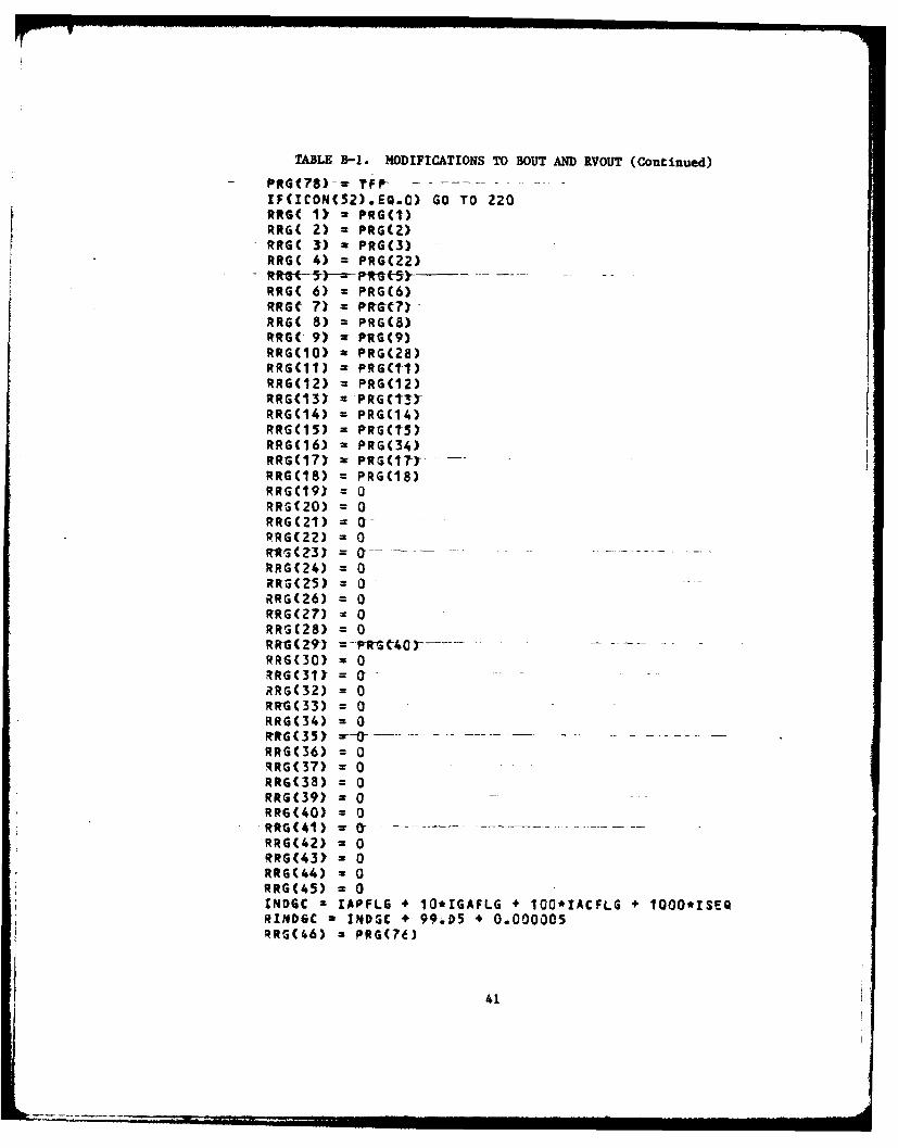
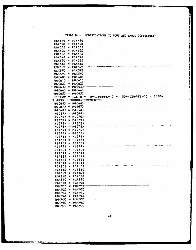
routine**... ... s . .... *..... *so ...... *** ...... *so**... se 25APPENDIX B - Modifications to BOUT (Boost Output) and RVOUT (Re-entry
APPENDIX D - TRW Program File Names Stored on Disk** ........ ....... 59APPENDIX E - TRW Program Subroutine Names and Calling Sequences. ..... 62APPENDIX F - Organization of the INTERP(Interpolation) Data Tables ... 64APPENDIX G - Flowchart of an Early MALIN Program ....... 09...... *...... 67APPENDIX H - Flowchart of the SDCTRL (Six-Degree-of-Freedom Control)
APPENDIX I - TRW Program Output Variables ...... **....o............. 84
v
LIST OF TABLES
Table Page1. Covariance Matrix of Measurement Noise, N.............. 62. TU70 Inputs for the Data Correlation Feature.**..*..**.**...... 73. Launch Site and Target*................. *................ i
AppendixTableA-1. Code Listing for the DATACORR Subroutine ......... . ....to 26B-i. Modifications to BOUT and RVOUT..o.....o.... ........... 39C-1. Targeting Program Inputs ........to...o...o....&..............*..... 53C-2. Glossary of Targeting Program Output Variables.*........... ... 54C-3. Glossary of Targeting Program Input Variableso..... o .......o... 056
C-5. Files Used for f eonSud..*.tio....n.* .... .. *y. 58C-6. Files Used for Trajectory P ro..*f i.l e# .. t ... *.o 58D-1. Subroutine File Names Stored on Di.*s...k.......... 60D-2. Files Contained on Disc For User Program H andling.... 61E-1. Subroutine Names and Calling Sequences ....... ... 63F-I. Aerodynamic Pressures .. ......... . ... .. .... o . . ..... ... ..... .. .... 65F-2. Aerodynamic Temperatures ......... .. .. ......... . ..... ....... 65F-3. Aerodynamic Coefficients ......... . .. . .. .. .. ... .. .. . .. . ... ...... 65I-1. TRW Program Output Variables ..... .. . .. . ... .... .... .. . .. .. 85
vi
LIST OF FIGURES
Figure page1. Crossrange vs. Downrange for Yaw Nozzle Deflections (5's)
Occurring at 30 Seconds into the Flight ......................... 132. Crossrange vs. Downrange for Yaw Nozzle Deflections ('s)
Occurring at 49 Seconds into the Flight ......................... 143. Pitch Body Angle vs. Downrange for Nozzle Deflections (6's)
Occurring at 30 Seconds into the Flight ......................... 164. Pitch Body Angle vs. Downrange for Nozzle Deflections (6's)
Occurring at 49 Seconds into the Flight......................... 175. Normal Accelerations vs. Time for Pitch Nozzle Deflections (6's)
Occurring at 30 Seconds into the Flight ........................ . 186. Normal Accelerations vs. Time for Pitch Nozzle Deflections (6's)
Occurring at 49 Seconds into the Flight ......................... 197. Normal Accelerations vs. Time for Yaw Nozzle Deflections (6's)
Occurring at 30 Seconds into the Flight........................ 208. Normal Accelerations vs. Time for Yaw Nozzle Deflections (6's)
Occurring at 49 Seconds into the Flight ......................... 21
AppendixFigureG-1.* Flowchart of Early MAIN Program. ..... .... ... .. ... ..... ... . .... ... 68H-I. Flowchart of SDCTRL Program .......................... ........... 77
vii
.. . ...... .. : ;,, , , ., ... .' ! I IIIIIII I III1II
I. INTRODUCTION
A. Statement of the Task and General Approach
This report documents the results of the work performed under thePershing II Task Order DAAhOI-81-D-A003, Delivery Order 0038 (CT/EESProject No. A-3165). The task order required that the following subtasksbe performed:
* The range safety problems which would arise if the motor nozzlewere unintentionally deflected during boost phase were to be evaluated.
* The aerodynamic simulation model used in a Pershing II computer-simulation program was to be validated against actual flight test data.
e Computer simulation results were to be compared with actual flightdata for a set of Tactical Ballistic Missile (TBM) trajectory profiles.
The results of these comparisons were "to be presented in a form use-ful for evaluation".
B. Background
The task documented with this report was an outgrowth of an earliertask (Pershing II Debris Studies, DAAHO1-81-D-A003, Delivery Order 0017,GT/EES Project No. A-2946). The earlier task was aimed at evaluatinglaunch and target sites for Pershing II firings, determining the effect ofvarying aerodynamic conditions on the missile's flight behavior, and con-ducting range safety studies. A follow-on task order request is in pre-paration and will expand upon the work performed in support of these twoprojects.
C. Contents of This Report
A detailed discussion of the subtask objectives and accomplishmentsis given in Section II. Section III discusses the U70 and TRW simulationprograms used to carry out Pershing II missile simulations [1]. It in-cludes a description of the U70 program and the computer on which it runs,modifications that had to be made to it to support this task, and theoperational procedures for running it. It also discusses the problemsinvolved in converting the TRW program to run on the U. S. Army MissileCommand's Perkin-Elmer 3220 computer. Section IV discusses the resultsthat were obtained in the execution of this task. Finally Section V pre-sents recomoendations for future work.
II. DETAILED OBJECTIVES
A. Subtask Objectives and Accomplishments
During the performance of this task, two of the three required com-puter simulation studies were performed, using the U70 trajectory simula-tion program [1] and the TRAJ targeting program. The third study, thecomparison of Pershing II computer simulation studies with actual flightdata, could not be carried out because flight test data were not availableduring the period of performance of the task. The effort that would nor-mally have been expended upon this comparison of flight test data and simu-lation results was directed instead toward the implementation of a MaximumLikelihood Method computer subroutine for data analysis.
Similar studies were to be undertaken using a new Pershing II simula-tion program developed by TRW, Inc., but the full computer program could notbe obtained in time for use on this task. Its treatment in this reportis necessarily restricted to a discussion of the conversion and docu-mentation of the program itself rather than the results obtained using it.A more detailed description of the four subtask objectives is given below.
1. Flight Safety (Motor Nozzle Deflection) Study
The motor nozzle deflection study was a flight safety study con-ducted to determine the breakup point of the Pershing II missile in theevent of an engine malfunction. A nozzle deflection would cause themissile to deviate from its normal flight path. The objective of the studywas to determine how quickly the missile would leave its flight corridor inthe event of a spurious nozzle deflection and whether Range Safety woulddetect this aberration in time to permit destruction of the missile beforeit could endanger life or property.
2. Aerodynamic Model Validation Study
A validation of the aerodynamic mathematical model used in theUT7O Pershing II digital simulator was required for utilization of flightdata. To compare the simulation results to the flight data, a statisticaltechnique called the Maximum Likelihood Method was to be used. This tech-nique de-serves special mention because of its key role in the performanceof this task. This technique is used to fit theoretically predicted valuesof relevant variables to experimentally derived values when the experimen-tal values contain random measurement errors. Generally, the MaximumLikelihood Method provides better estimates of the underlying true valuesof variables than a least-squares curve fit because, in making its estima-tee, the Maximum Likelihood Method uses a prior knowledge of the standarddeviations of instrument measurement errors as additional information tohelp refine its estimates.
2
3. Tactical Ballistic Missile Trajectory Study
The Tactical Ballistic Missile (TBM) study took the form of amatrix of U70 runs with various flight paths along one dimension and dif-ferent flight characteristics along the other dimension.
One launch site and three target sites were used to generate thethree flight paths. Then for each flight path, a set of three runs wasmade for three assumed conditions - first, a "nomin"i motor" or unperturbed-baseline flight plan; second, a ballistic re-entry vehicle flight plan inwhich no aerodynamic corrections are applied to the missile during its ter-minal re-entry phase; and third, a flight plan assuming offsets in targetlatitude and longitude from its normal target location. Thus, a total ofnine runs were made for this study.
B. Conversion and Installation of The TRW Simulator
The TRW program is a six-degree-of-freedom simulator developed forthe purpose of validating Pershing II onboard software. This simulatorco>ntains aerodynamic modeling features and provides simulation capabilitiesnot found in the U70 simulation program - capabilities which the U. S. ArmyMissile Command's Systems Simulation and Development Directorate, SystemsEvaluation Branch, seeks to add to its repertoire of simulation programs.The job of understanding the program and converting it to the MissileCommand's computer was assigned to Georgia Tech as a part of this task(A-3165). TRW delivered a copy of its program to the Systems EvaluationBranch. However, when program compilation and link loading was attempted,certain sections of the program, such as the MAIN control program and theINTERP routine were found to be missing. These could not be obtainedduring the period of performance of the task, and therefore, could not beconverted. Insofar as possible, the remainder of the program was partiallyconverted from TRW's Digital Equipment Corporation VAX 11/780 computer tothe System Simulation and Development Directorate's Perkin-Elmer (PE) 3220computer after making minor changes to accommodate for the differences bet-ween the FORTRAN capabilities of the two computers.
Although the installation of the TRW program on the PE 3220 computerand the incorporation of its aerodynamic model within the U70 program isnot explicitly required in this task's scope of work, it is implicitlyrequired for the proper performance of the task. Since it has consumedmuch of the task's effort, it will be discussed in this report as though itwere a fourth task objective.
3
III. THE U70 AND TRW SIMULATION PROGRAMS
A. The U70 Program
1. Description of the U70 Program
The U70 trajectory program employed in the performance of thistask, uses the given prelaunch, target, and flight conditions to simulatethe flight of a single-stage or two-stage missile and its associatedmaneuvering re-entry vehicle. This program utilizes the equations andrequirements found in the Pershing Launch Computer and the PershingAirborne Computer to simulate the missile flight from launch through theboost, midcourse, and terminal portions of flight to impact [2].
The U70 trajectory program runs on a Perkin-Elmer 3220 computersystem equipped with 800 kilobytes of random access memory, a nine-tracktape drive, three 67-megabyte disk drives, and five demand terminals(including the system console). The simulation is coded in FORTRAN VII-D,although it is probably compatible with other versions of FORTRAN.
The program is able to restart the missile simulation at anytime during the terminal re-entry portion of flight upon entry of data suchas time, position, velocity, and orientation of the missile at the desiredrestart time, plus the restart data acquired from a previous simulation.
2. Modifications to the U70 Program
a. Modifications for the Motor Nozzle Deflection Study
For this study, modifications were made to the U70 program'sBAPLT (Boost Autopilot) subroutine to enable desired deflection angles tobe input at some time during boost. These modifications are as follows:
MODIFICATIONS TO BAPLT
470 CONTINUEIPND - ICON(50)IYND - ICON(51)IF(IPND .EQ. 0) GO TO 453IF (TIMC .LT. CIN(382)) GO TO 453DNV (1, 1) - CIN (380) * DTOR
453 CONTINUEIF(IYND .EQ. 0) GO TO 454IF(TIMC .LT. CIN(382)) GO TO 454DNV (1, 2) = CIN(381) * DTOR
454 CONTINUE
RETURNEND
4
b. Aerodynamic Model Flight Validation
As mentioned previously, the Maximum Likelihood Method (MLM)of data correlation was intended to help fit the simulator-generated aero-dynamic flight data to the actual test-flight telemetry data, i.e., to"average out" random telemetry instrumentation errors in order to providemore meaningful comparisons between the simulated and experimental results.The machinery for accomplishing this was incorporated into a new U70subroutine called DATACORR. The addition of DATACORR to the U70 programrequired the creation of a new link procedure, TU70LINK.CSS, which builds anew task called TU70.
The TU70 task requires as inputs the instantaneous inertial-frame X(t), Y(t), and Z(t) position coordinates and 0(t), e(t), and 0(t)(roll, pitch, and yaw) angular coordinates of the missile and their timederivatives (where t represents time). For program checkout purposes,constant offsets have been programmed into the inertial position and rota-tion inputs. Since the MLM uses an iterative technique, an upper limitmust be entered on the number of iterations that the computer is to attemptbefore giving up (in case the iteration sequence does not converge).Finally, a 6 x 6 matrix of standard deviations and cross-correlations ofmeasurement noise must be entered for the three position and the threerotation coordinates at t - 0, e.g., at launch (Table 1).
This matrix contains in its [1, 1] location, the variance (02)
of the instrumentation measurement errors of the missile's x-coordinate att = 0. In its [1, 2] location, it contains the mean square error in X dueto an error in Y (a~), and so forth, for all 36 elements. These TU70
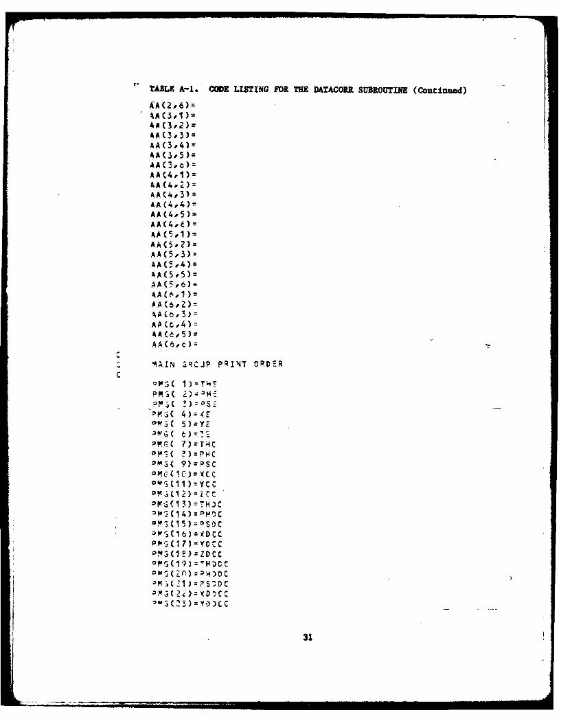
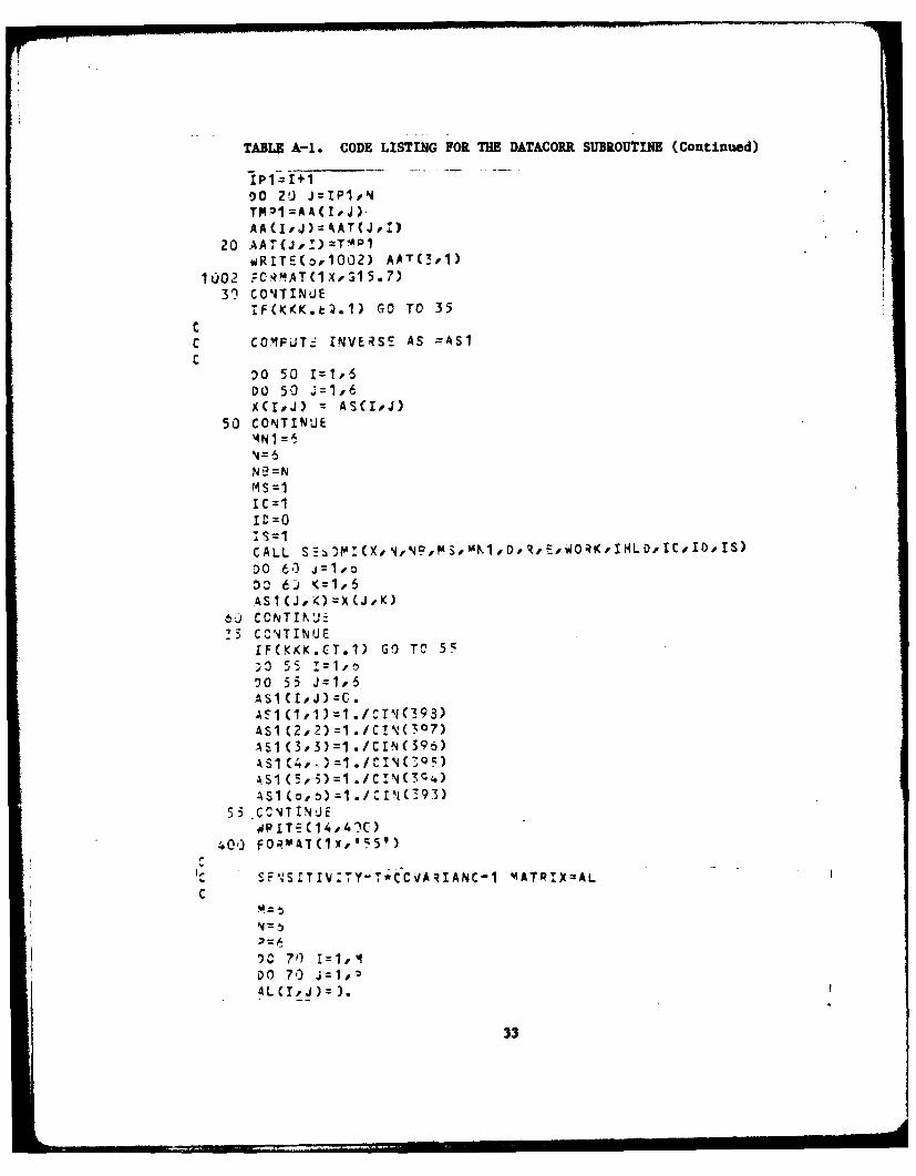
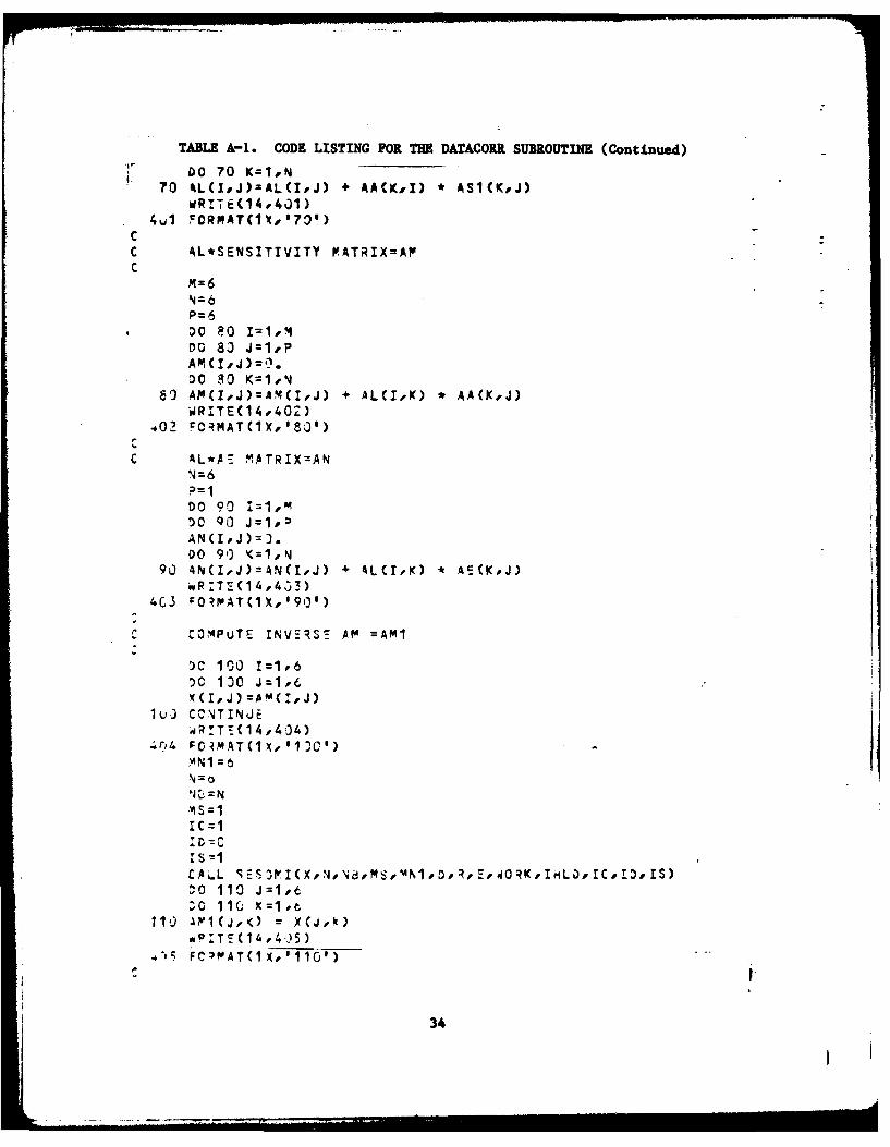
input requirements are summarized in Table 2. The coding for the DATACORRsubroutine is reproduced in Appendix A.
c. Data Format Modifications for the Tactical BallisticMissile Simulations
Modifications were made for the Tactical Ballistic Missiletrajectory simulations to provide the same output format for all stages offlight. Different variables were output for the boost and for the re-entrystages; these variables were combined to produce one block of output datafor both stages. This required changes in the BOUT (Boost Output) andRVOUT (Re-entry Vehicle Output) subroutines. These changes are documentedin Appendix B.
5
TABLE 1. COVARIANCE MATRIX OF MEASUREMENT NOISE, N
2 2 a2 a2 a2 02ox By ez
a 2 a2 C2 a 2 a2 C2
y6 * x y oz
a2 aT2 02 a2 2 ac2ipeipi ix lpy ipz
a2C r 2 a2 a2
Ie X0 X xi
C2 a2 a2 a2 o2 a 2
yeYO yi IPyx y yz
c12 C2 ~ r2 ~ a2 a2 aY2ze zo 0 zx zy z
i6
TABLE 2. TU70 INPUTS FOR THE DATA CORRELATION FEATURE
INDICATORS:
CIN(75) - Contains an on-off "switch" for the data correlation feature(0 - Off, I - On)
CIN(70) - Contains an on-off "switch" for the computation of the transposeof the sensitivity matrix, S (0 - Off, I - On)
CONSTANTS:
CIN(499) - Contains the number of experimental data points
CIN(498) -x2
CIN(497) = ay2
CIN(496) - az2 Contains the initial inputs of the co-var.Lance matrix of the measurement
CIN(495) - a82 noise (assumes a diagonal matrix)
CIN(494) - a02
CIN(493) - aq,2
CIN(492) - E6
CIN(491) - E0Contains the error-vector differences
CIN(490) - E* between the measured and computed valuesof x, y, Z, 8, 0, and
CIN(489) - Ex
CIN(488) - Ey
CIN(487) - Ez
7
3. Instructions for Using the U70 Program
A description of the procedures for compiling, running, linking,restarting the program, and making output tapes is given in Appendix C,together with a list of the .CSS files used to accomplish these tasks, anda list of the U70 source files.
The TU70 program contains an array of input constants and indica-tors called CIN. Table 2 contains definitions for the constants and indi-cators which serve as inputs for the DATACORR subroutines for the TU7Otask.
B. The TRW Program
1. Compiling the TRW Simulation Program
The TRW program was originally set up for interactive com-pilation, program linkage, and execution. However, in converting theprogram to the Perkin-Elmer 3220 computer, it became necessary to switch tobatch mode compilation and linkage. The reason for turning to batch modeoperation was that not every file or function required by the program ispresent in the program itself. Some of the necessary information is storedin independent files, and operating in batch mode permits these independentfiles to be found during compilation and to be linked to the MAIN programduring the program linkage phase. To accomplish this result, the SBATCHcommand had to be placed at the beginning of the program, the $BEND comandat the end of the program, and the SPROG declarations put at the beginningof each subroutine.
Next, a "compile file" was produced by modifying a copy of thesystems file F7CAE.CSS (which contains the FORTRAN VII compiler and thelinking loader) and then using it to compile the TRW program. Compilationtime was saved by compiling one subroutine at a time, producing an objectcode image and saving it in a separate file, and then linking it togetherwith other object code subroutines during the link phase. This meant thatonly those subroutines which had been updated had to be recompiled.
F7CAE.CSS is a procedure which compiles and links any program.The compiler in F7CAE.CSS uses system file F7D.TSK to produce an objectfile and F7D.ERR to record errors found during the compile phase. TheF7CAE.CSS link loader processes object files generated by the compiler andcreates a task file for execution. The link loader also creates a load mapand provides a record of any undefined external references or symbols.Appendix D lists the file names used by the TRW program and Appendix Elists the program's subroutine names and calling sequences.
8
Of the many error messages which surfaced during the first com-pilation, a substantial fraction was associated with VAX-peculiar FORTRANINCLUDE statements. INCLUDE is a VAX FORTRAN compile-time command whichcauses the compiler to copy a disk file into a program - typically, a filecontaining COMMON and EQUIVALENCE statements. This permits a simpleINCLUDE statement to be substituted in subroutines for the extensive COMMONand EQUIVALENCE statements that would ordinarily be found there instead.This practice not only reduces the amount of effort required to write andupdate the program but also reduces the chances of making a mistake incoding, since the COMMON and EQUIVALENCE statements only have to be updatedat one place in the program rather than in every subroutine in which theyare referenced.
Another VAX-peculiar FORTRAN VII enhancement is the DO WHILE com-mand. Since the DO WHILE statement is not recognized by Perkin-Elmer'sFORTRAN VII compiler, it was necessary to replace DO WHILE's in theoriginal program with ordinary DO statements in the Perkin-Elmer version ofthe program.
The above modifications constitute the principal programmingchanges that have so far had to be made to the TRW subroutines in order toconvert them from the VAX 11/780 computer to the Perkin-Elmer 3220 com-puter.
2. Subroutines Missing From the TRW Program
As mentioned in Section II.E., the TRW simulation program wasdelivered with some major portions of the program missing. The most cri-tical missing subroutine was INTERP(Interpolation) which, by interpolatinglarge data tables, would have provided the thrust characteristics, massproperties, and aerodynamic data needed to simulate the flight. The maincontrol program, MAIN, was also missing, although a program SDCTRL(Six-Degree-of-Freedom Control) was found which seems to perform similarfunctions. Essential portions of the program that were required to simu-late steering, guidance, and navigation in the Pershing Airborne Computerwere also missing. Finally, an error message routine ERRMSG was missing.
a. INTERP(Interpolation)
With the aid of a former developer of the TRW INTERP routine,a prior version of INTERP was located in an earlier edition of the TRWsimulator and efforts were made to understand it and use it in the currentversion of the TRW program. At the heart of the INTERP routine is theabove mentioned involved set of aerodynamic tables, organized in a way thatminimizes storage requirements without unduly increasing run times. Adiscussion of what has been learned about this multi-dimensional data tableis presented in Appendix F.
9
b. MAIN and SDCTRL (Six-Degree-of-Freedom-Control) Programs
After finding that the MAIN routine was missing from the TRWsimulator, efforts were begun to develop such a function-controllingroutine. An earlier version of MAIN was found in a program listing and thelisting was used to help understand what was needed to recreate a currentMAIN routine. A flowchart of this early version MAIN routine is containedin Appendix G. Appendix H contains a flowchart of the SDCTRL routine.
c. The Output Processor
The TRW simulation program has an output processor which takesadvantage of large arrays to store values of variables for output. Thesearrays are saved in three groups named BIG0IR, BIGOIt, and BIGOID, whichcontain Real, Integer, and Double Precision variables, respectively. Theseoutput-variable values are transferred to the BIG01 arrays for use by theoutput processor through EQUIVALENCE statments located in eachsubroutine [1]. Each variable stored in BIGO1R, BIG01I, and BIGOID isstored on a disk file BIGOI.DAT. The names of these variables are listedin Appendix I.
3. Tape-to-Disk Conversion of the TRW Program
TRW delivered its simulation program to the System EvaluationBranch on a nine-track 1600 bit-per-inch tape. This was loaded onto aPerkin-Elmer 3220 disk pack using the following procedure:
Mount the tape on a 1600 bpi tape drive.> COPY> AL FILEI.FTNIN,80> OUT FILEI.FTN> COPY *,*
10
IV. RESULTS
A. Flight Safety (Motor Nozzle Deflection) Results
As mentioned earlier in Section II,B, this Pershing It missile simu-lation was carried out using the U70 simulator to determine what would hap-pen if, through some hardware failure, the nozzle were accidently deflected
during a live missile firing. In carrying out these simulated flighttests, the missile was allowed to "fly" unperturbed (in the computer) for ashort time. Then the motor nozzle was deflected by a pre-determined angleand the simulation continued until either the missile's total angle ofattack exceeded 15* or the normal (perpendicular to the body of themissile) acceleration exceeded 5 g's. Either one of these occurences wasassumed to generate sufficiently unstable conditions that breakup of themissile would occur, so the simulation was terminated at that point.
The spurious nozzle deflections were assumed to occur at 30 seconds and
at 49 seconds into the flight. The 30-second flight time was chosenbecause, at 30 seconds, the aerodynamic forces acting on the missile would beat or near their maximum, i.e, a worst-case condition. The 49-secondflight time was chosen because it is almost at first-stage burnout, and is
a time when missile failure is likely. Three nozzle deflection angles weretried, 0.50, 2', and 7.60, first in pitch and then in yaw, leading to atotal of twelve cases (two deflection times and three nozzle deflectionangles, first in pitch and then in yaw). All the cases were simulatedflights from McGregor, New Mexico, to McDonald's Well, New Mexico, with the
targeting conditions given in Table 3 below. Before presenting theseresults in detail, some data comparison problems need to be discussed.
TABLE 3. LAUNCH SITE AND TARGET
McGregor, NM LAUNCH SITE
Latitude - 32.095750Longitude - -106.2035 °
Altitude - 1251.0000 m
McDonald's Well, NM TARGET SITE
Latitude - 33.1135800Longitude - -106.35897 °
Altitude - 1228.00000 m
11
In order to provide a standard by which to compare the deviated-nozzle runs, a nominal or baseline simulation was run in which it wasassumed that the missile followed a nominal, undeflected flight plan.Since the deviated nozzle results were printed at 0.1 second intervals, itwould have been advantageous to have also printed the baseline results at0.1 second intervals for purposes of comparison. Unfortunately, the largevolume of printout generated by the U70 program made it impractical toprint results at 0.1 second intervals, and the results were available onlyat 1.0 second intervals. Consequently, the baseline results had to beinterpolated at 0.1 second intervals in order to compare them to thedeviated-nozzle results, i.e., a direct comparison was not possible.
A second data comparison problem resides in the fact that, forunknown reasons, the first data points in the deviated-nozzle simulationprintouts (the results for 30.0 seconds and the results for 49.0 seconds)are invalid. These 30- and 49-second numbers are not random but seem tocome from some earlier time in the flight. Subsequent results appear to becorrect when compared to the unperturbed flight results. For example, theinterpolated unperturbed flight results for 30.1 seconds agree to fourdecimal places with the deviated-nozzle results, with subsequent datadeparting from the baseline data in a regular and reasonable way. It isthe authors' conclusion that the faulty first point in each set of numberswas the result of a print-routine malfunction rather that an error in thedeviated nozzle results. However, the reader needs to be aware of thischaracteristic in the data.
Figure 1 depicts the missile's flight path for an unperturbed flightplan and for the three different yaw-axis nozzle deflection angles lookingdown from above when the nozzle deflections occur 30.0 seconds into theflight. Figure I is a plot of downrange coordinates versus crossrangecoordinates. The "straight line" in Figure 1 represents the path of anunperturbed missile. (It curves about 1 to the right but the curvature istoo small to be visible in the plot.) For all three deflections, themissile disintegrates because the yaw angle of attack exceeds 15" ratherthan because the normal acceleration exceeds 5 g's. Note that for thesmaller the nozzle deflection angle, the farther the missile can travelbefore it reaches the critical angle of 150.
Figure 2 shows a similar plot when the nozzle deflection occurs 49seconds into the flight. Note that the flight path deflections appear tobe smaller than they were when the nozzle deflection occurred at 30 seconds(Figure 2). In reality, the deflections are the same but the velocity ofthe missile is greater, and this increases the horizontal scale of theplot. (The results for a nozzle deflection of 7.6* are missing because ofa faulty computer run.)
12
00
0o 0
*0
;* 0
a
0 Nw
'0 13
pa 0
to'0
-4
In w
141
Figure 3 shows a plot of the missile vertical pitch angle versus itsdownrange coordinates when a nozzle deflection in pitch occurs at 30seconds, and Figure 4 depicts similar plots for the 49 second pitch nozzledeflection.
Figures 5 through 8 show how the normal (lateral) accelerations ofthe missile vary with time. An examination of these curves confirms thatin every case, the simulated flights terminated before the normal accelera-tions exceeded the destructive limit of 5 g's, i.e., the flights terminatedbecause the missile's total angle of attack exceeded 150. There is aninteresting tendency for these normal accelerations to rise, dip, and thenrise again. No simple explanation has been advanced for this behavior,although the Pershing II guidance system is sufficiently complex that acomplex response might be expected in the event of a major nozzle deflec-tion malfunction. (The results for a nozzle deflection of 7.60 are missingbecause of the faulty computer run mentioned previously in connection withFigure 2.)
These simulations show that the missile would leave its allowableflight corridor and exceed the allowable angle of attack within approxi-mately one second.
B. Aerodynamic Model Validation Results
As mentioned in Section II.B., this study could not be completedbecause Pershing II flight test data were not available in time.
In support of this task, the DATACORR subroutine, incorporating theMaximum Likelihood Method of data correlation, was written, compiled, and,insofar as possible, was tested. However, one important part of thissubroutine, the derivation of sensitivity coefficients, was not completed.
C. Tactical Ballistic Missile Trajectory Results
As mentioned in Section II.C., nine U70 runs were made for this studyfor nine input trajectory profiles. Three of these profiles entailed off-sets in target latitude and longitude.
When the study was completed, the results were output on tape and deli-vered to the sponsor.
15
I.0
*z
o 0
P0
00
0
.4
16b
7-j
00
0 U0
to IA
-4
goU
4 fie P
(Saata nx LosHoi17'
1-0,
0
0
41
ri)d
* 0j
oorxmv-vo
C.','18
0 U0
0
100
100
E-4
100
'41"4
o 0z 0d
N '-4
* to
19N
o I..
'0 0
10
'0
4.'
00
41
E-4
I1 >02A
N.3
z 0o
@4.
200
*0 L0
10
rd'0
0
@1-
0
o 0
004z
IA.Apr
moijra'l3DD TfM)
21
D. Conversion and Installation of the TRW Simulation Program
Some of the details of the TRW program conversion have been discussedin Section IIIoB., and in Appendices D through I. A summary of the resultsis as follows:
1. All subroutines except those missing from the incomingprogram tape were converted and successfully compiled.
2. The organization of the INTERP tables was deciphered anddocumented (Appendix F).
3. The MAIN and SDCTRL subroutines were flowcharted (AppendicesG and H).
4. A linking task builder TRWLINK.CSS and a compiler task builderDAVEF7.CSS were created to accommodate the TRW program.
22
V. RECOMMENDATIONS FOR FURTHER WORK
A. Flight Safety (Motor Nozzle Deflection) Recommendations
One of the recommendations for future work is to carry out theseevaluations, re-running the simulation with print statements that monitorthe moment-by-moment variations in the angles of attack, the down-range andcross-range coordinates, and the inertial flight path angles before,during, and after the moment when the nozzle deviation occurs.
B. Aerodynamic Model Validation Recommendations
Reco-mmendations for future work consist of completing the DATACORRsubroutine and carrying out the study using actual flight data.
Normally, in employing the Maximum Likelihood Method, all the com-puted constitutive forces and moments that make up the total X, Y, or Zforces or 0, 0, or 0 moments (constituents of lift, drag, etc.,) are com-pared individually, with their equivalent measured values. However, theaerodynamic model used in the U70 simulator is not yet sufficientlydetailed to permit making these comparisons because of the difficulty ofattributing corrections to individual components of the U70 predictions, sothe comparisons are to be made at the level of overall body forces andtorques. For this reason, the DATACORR subroutine doesn't presently outputits force and torque corrections to the main U70 program. However, futureplans call for the upgrading of the main program to provide aerodynamicmodeling at the constitutive level. When that is done, the DATACORRsubroutine and the TU70 task will be upgraded to output these correctionsto the U70 program.
C. Tactical Ballistic Missile Trajectory Recommendations
Recommendations for further work depend upon the sponsor's require-ments.
D. Conversion and Installation of the TRW Simulation Program
The Maximum Likelihood Method correlation technique being used tovalidate the U70 simulator predictions against actual flight data (SectionII.C.) should be used to evaluate the TRW simulator.
Recommendations for future work consist of completing the conversionand installation of the TRW program, using it to simulate Pershing II testflights, and comparing its results with the actual test flight data.
23
REFERENCES
[11 "U70 Utilization Report," Martin-Marietta Corporation, Orlando,Florida, Revision A, January 27, 1981.
[2] "Computer Program Missile Interim Detail Specification/Performance/Design Requirements for Pershing Airborne Computer Program forPershing II Weapon System, Engineering Development Program,"Specification MIS-21748, Martin-Marietta Corporation, October 1,1980.
24
24
APPENDIX ACODE LISTING FOR THE DATACORR (Data Correlation) SUBROUTINE
25
TABLE A-i. CODE LISTING FOR THE DATACOIR SUBROUTINE
CTHC OS (TRC)STL4C SrN (T4C )cp~$c~C3~(P~IC)sric=s~im P c,cpsc=c OS (P SC)SPSC:SIh (PSC)Ajl1=CPSC*CTHC-S7SC*SPHC*STHCA212L'CTH.C*SPSC4STHC*SDP4C*CPSC4 P1 3 =- ST ! C *C H CAe 21 =-Sr- 3C *C HCA922=CPHC*CSCAFeZ3=SPHckP31=CPSC*'ST4qC.CTHC*SPHC*SPSCAE32=STkC*PSC-CTIHC*3P'4C*CPSCA633=CTHC*CPHC
c SENSITIVITY MATRIXC
AA(1,2)rAA(1,.3)=A 4(1,4) =AA(1,5)z
~A CZ,1)=
AA ( ,4 )=AA (2,5):
30
TABLE A-I1. CODE LISTING FOR THE DATACORI SUBROUTINE (Continued)
U70 PROGRAM .CSS (Command Substitute System) SOURCE FILES
The Perkin-Elmer 3220 computer on which the U70 program was run, has adevelopment compiler which compiles rapidly but produces slow-runningobject code, and an optimizing compiler which compiles slowly but producesfast running code. The development compiler was used to compile the U70program, since compile times rather than execution times were at a premiumduring the period of performance of this task. As stated in Section III,B,in order to further reduce compile times, each subroutine was assigned itsown data file so that one could recompile one subroutine at a time ratherthan having to recompile the whole program each time a change was made inone of the subroutines.
There are two .CSS commands that can be used to actually carry out acompilation: U70CA and U70C. The U7OCA command compiles all the PershingII source files, while the U7OC command is used to compile an individualsubroutine. The specific job control sequence which initiates the U70 com-pilation is as follows:
U70 @1, @2, @3, @4, @5
@1 Input source file@2 Object filk utam" (defaults to @1.0BJ)@3 List file name (defaults to @I.LST)@4 Start option(s) sepaated with spaces (defaults to
no options)@5 Load size for F7D (defaults to 50K bytes).
A cross-reference listing can be obtained by including the command XREF inthe @4 list of start options.
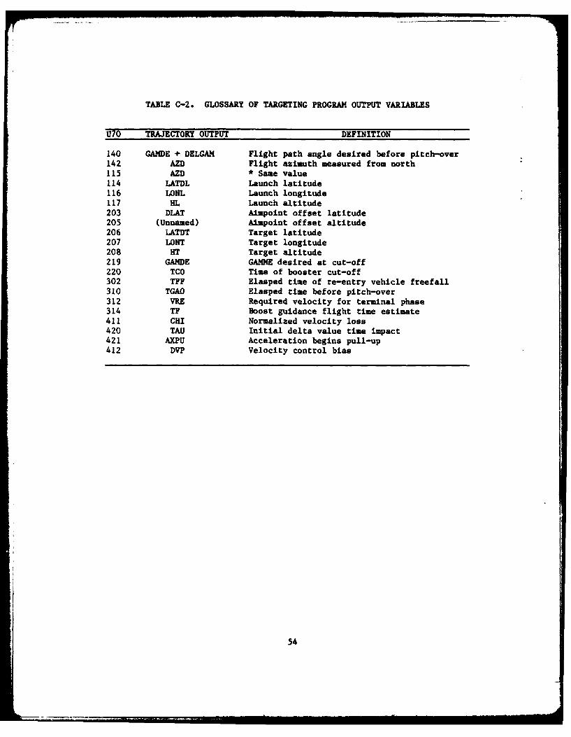
A preprocessing program called TRAJ must be run before the U70 programis ready to run. The TRAJ program is derived from equations resident inthe Pershing Launch Computer, which is located on board the missile. Giventhe launch and target latitude, longitude, altitude, and the number of sta-ges (Table C-I), it computes launch presets and transmits them to the por-tion of the program which simulates boost and terminal guidance. This, inturn, generates a data file containing estimates of the desired velocitiesand cutoff angles, estimates of flight and pitch-over times, and targetoffsets (Table C-2). The U70 program uses these outputs to make its owncalculations, interpolating the TRAJ output tables.
Execution of the U70 program is initiated using the routines UST2 orUST3. These commands invoke .CSS files containing other commands to loadthe task, make logical unit assignments, and start the task.
52
The UST2 routine is used in order to make a full run (flight fromlaunch to impact). The inputs to UST2 are obtained from the TRAJ programsand are used to build a new data file (logical unit 11). This file isused to create a new input tape in the U70 program, TAPE 11. The outputfrom UST2.CSS is printed at time intervals whose value is input inConstant 271, or is printed at any point along the flight path where adiscontinuity appears (such as the end of the boost phase, the apogee,etc.,).
The subroutines in the U70 program are linked using the .CSS coandU7OLINK. This command builds an overlaid executable task. For example, itensures that copies of all of the subroutines called within a givensubroutine are present within that subroutine.
TABLE C-I. TARGETING PROGRAM INPUTS
ITRS - 210 Single Stage220 Two Stage
LONT - Longitude of the TargetLATDT w Latitude of the TargetHT - Altitude of the TargetLONL - Longitude of the Launch SiteLATDL - Latitude of the Launch SiteHL - Altitude of the Launch Site
53
TABLE C-2. GLOSSARY OF TARGETING PROGRAM OUTPUT VARIABLES
U70 TRAJECTORY OUTPUT DEFINITION
140 GANDE + DELGAM Flight path angle desired before pitch-over142 AZD Flight azimuth measured from north115 AZD * Same value114 LATDL Launch latitude116 LONL Launch longitude117 HL Launch altitude203 DLAT Aimpoint offset latitude205 (Unnamed) Aimpoint offset altitude206 LATDT Target latitude207 LONT Target longitude208 HlT Target altitude219 GAMDE GAMME desired at cut-off220 TCO Time of booster cut-off302 TFF Elasped time of re-entry vehicle freefall310 TGAO Elasped time before pitch-over312 VRE Required velocity for terminal phase314 TF Boost guidance flight time estimate411 CHI Normalized velocity loss420 TAU Initial delta value time impact421 AXPU Acceleration begins pull-up412 DVP Velocity control bias
54
.. . I I 2 .. ... !... . .. . . . II I I | i lra IIwo o l .. . .
U7OLINK is structured so that it contains four overlays. The firstoverlay includes a subroutine called MINIT.OBJ, which presets all variablesto zero. The second overlay includes ENPUT.OBJ, which creates a new inputdata tape. The third overlay includes all binary files appropriate to theboost phase of simulation. The fourth overlay includes all re-entry-vehicle binary code.
In addition, U7OLINK creates a load map, U70-U7OLINK.MAP, that is use-ful for debugging purposes. Control indicators are input to set flightoptions, and program constants are entered to control the initial con-ditions, multipliers, limits, errors, print controls, etc. Aerodynamic dragand atmospheric data are input through the tabular data portion of theinput file. A list and description of these data inputs is given inReference 1.
After a full run has been made, a restart can be created using theoutput from UST2.CSS and the UST3.CSS command. The restart procedure isa very useful tool in a study where new conditions are imposed on a missileat a certain point in flight. However, the restart could not be used forthe nozzle deflection study, since a restart could not be made during theboost phase. Certain values which appeared in THRUST were functions of timeand could not be re-initialized at the arbitrary time desired for a restart.
The values which are required to be input into the UST3.CSS data file ofUST3.CSS are listed in Table C-3. Tables C-4, C-5, and C-6 list other U70files used in the performance of this task for the benefit of anyone whomight want to initiate U70 runs.
The procedure of outputting U70 flight data to tapes required thatmodifications be made to the subroutines BOUT (Boost Output) and RVOUT(Re-entry Vehicle Output). The desired output was written to logical unit14 and a .CSS file was created, with logical unit 14 set to MAGO, to writethe data to the tapes.
TABLE D-2. FILES CONTAINED ON DISC FOR USER PROGRAM HANDLING
The following files are used:
DAVEF7.CSS - Used to compile each subroutine file.TRWLINK.CSS - Used to link the TRW 6DOF simulator.DCOMMENT.FTN - Contains comments which describe the function of eachsubroutine.TRWRV.DAT - Contains re-entry aerodynamic data.TRWSS.DAT - Contains single stage aerodynamic data.TRWTAB.FTN - Used to read TRWRV.DAT and TRWSS.DAT and string them into along one dimensional array. TRWTAB.CSS is used to run this program andTRWTAB.DAT contains the output of the TRWTAB.FTN.BIG01R.DAT, BIGOII, BIGOID - Contain variables defined in the program andtheir storage locations in the BIGOI arrays, as specified by EQUIVALENCEstatements.
The following files are used in the $INCLUDE statedents to handlecommon blocks and equivalence statements.
APPENDIX FORGANIZATION OF THE INTERP(INTERPOLATIOM) DATA TABLES
64
APPENDIX F
ORGANIZATION OF THE INTERP(INTERPOLATION) DATA TABLES
An interpolation routine called INTERP forms the backbone of the TRWprogram's aerodynamic simulator, and utilizes a large set of multidimen-sional tables to generate its results. The multidimensional interpolationprocess is straightforward and is described with the aid of the followingexample.
Suppose that we have a table of pressures:
TABLE F-1. AERODYNAMIC PRESSURES
0 0.1 0.3 0.5 (bars)
and a table of temperatures,
TABLE F-2. AERODYNAMIC TEMPERATURES
10000 1300 ° 1600*
The pressure and temperature are considerd to be independent variables.Associated with these independent variables is a table (Table F-3) of aero-dynamic coefficients, C:
Now suppose that we are given pressure, P, - 0.3306 (bars) andtemperature, T, - 11160, and we want to interpolate to find the aerodynamiccoefficients that correspond to these values of pressure and temperature.First, the interpolation routine tests the input pressure value P, againstthe table of pressures and determines that the input value P, - 0.3306 liesbetween 0.3 and 0.5. The location of the upper number - the "0.5" - isread out and stored in a variable which might be labeled "PINDEX" forPressure INDEX. Since 0.5 is the fourth element in this independentvariable table, the number stored in PINDEX is a "4", and it is a pointerto the interval in the independent variable table in which 0.3306 islocated.
65
Next, the same operations are carried out for the temperature, usingthe temperature table. Since the temperature lies between I000 and 1300,the location of the 1300* value - location #2 - is stored in TINDEX(Temperature INDEX) to designate the proper interpolation interval.
Finally, the two index values, 4 and 2, are used to locate the inter-val around the 4th row and 2nd column of the dependent variable table ofaerodynamic coefficients (Table F-3). Then the pressure and temperature tobe evaluated, P - 0.3306 bars and T - 11160, are used to carry out theactual interpolation, in order to obtain the interpolated values of theaerodynamic coefficients.
In the listing of the INTERP subroutine's data output, the followingcommands appear:
BEGININDEPENDENT TABLE OUTPUT VARIABLE/
INPUT VARIABLEDEPENDENT TABLE OUTPUT VARIABLE/
INPUT VARIABLE, INPUT VARIABLEEND.
At first, these were thought to be VAX 11/780 commands. Later, itwas determined that the TRW program contains its own data input processorand logical analyzer, which reads and interprets input data tapes,including the above statements. Apparently, these table definitions areused only for printer output formatting. Using the example given above,these statements would take the following form:
BEGININDEPENDENT TABLE PINDEX/PRESURINDEPENDENT -TABLE TINDEX/TEMPDEPENDENT_T ABLE AEROCO/PINDEX, TINDEXEND
When the results are printed out, AEROCO, standing for "AerodynamicCoefficients", would be printed at the top of the column listing the aero-dynamic coefficient values which INTERP generates by table interpolation.
66
APPENDIX GFLOWCHART OF AN EARLY MAIN PROGRAM
67
MAINntiains
INCLUDE ,=o___'wn andZ a'ilivalenceStatements
FLOGICAL ONETIM
I DATA
INITIALIZATIONIPrompt touser forsource file
Figue G-. F~wchaTfal y ANPorm
AN 68FG AS
F
ERRFW>FALSE,A0
TRUE
ERRCLS - 4
CALL SCERR
ONETIM FALSE
TRMFLG FALSE
TRUE
READ SFILE
26
Figure G-1. FLowchart of Early MAIN Program (Continued).
69
4
2
SFILE; >FALSE
BLNK(1:40)
TRUE
IDRNAM - SFILESFILE - BLNK(1:40)
EXTFLG - 11
CALL REDIDR
TRUE ERRFLG FALSE
K A
E
0
ERRFLGA .4
10 5
SFILE
ERRCLSCALL SCERR ERRFLG 0
TLMFL.G - ZFATAL
A
Figure G-1. Flowchart of Early MAIN Program (Continued).
70
E D
PJJET TRUE SFILE FALSE
j<
BLNK (1:40
FALSE
ROTNAN
SFILE71:20)ROTNAM IDRNAM
SFILE(1:40)BLNK(1:40)
I GO TO 100
ERRFLG - 01 40
GO TO 100
ERRFLG, - 02 50
GO TO 100
ERRFLG - 03 1 60
GO TO 10 100
T END IF
ERRFLG FALSE
0
TRUE
G
Figure G-1. Flowchart of Early MAIN Program (Continued).
71
G H
ERCS -4QUAL(1:40) -SFILE
CALL SCER4FALSE TRMPLG;
FALSE(2 IORFLG) 1
IOFLG - 11
Do 240 11BUSPNT(1, IOFLG),BUSPNT(2, IOFLG), 1
BIGO21(PACLNK(II)-
L ~~ K BIGOII(SIL (II)
2
L j K
TRU LER FALK
FiueMINI Fl1hr ofEryMIIrga CnItiud)
CAL73 CR
L J K0 P
LNTF -K
Figure~CAL G-. lwcar f al ANPoJ(otne)
FALSETRM74
L J K Rs 0P
Figure G-1. Flowchart of Early MAIN Program (Continued).
75
APPENDIX HFLOWCHART OF THE SUBROUTINE SDCTRL
(SIX-DEGREE-OF-FREEDOM CONTROL) PROGRAM
76
SDCTRL
FALSE INITFL TRUE
0
FALSE INITFL
TRUE
CALL DRAND
INITIALIZATION1
LALR - LAL*DTORLOLR - LOL*DTOR
<
PWRFLG
FALSE
TRUE
ISEQ 10CALL MONISEQ - 20
ISEQ 70ISSEEND IF CALL NAVON
ISEQ 80CALL STINIT
I El
CALL IMSALNCALL IKSPLS
-ENE IF CALL RADARCALL DCU
AAz
Figure H-1. Flowchart of SDCTRL Program.
77
A AA
TMEWELS SIMTIM +
DELTIM
FALSE IFISEQ
20
FALSE ELSEIF ISEQ
30CALL STINITCALLIMSSST
E IF TRUECALL ALNONISE - 40
IF SEISEQ -40
TRUE
CALL STINCT,IMSALN, 124SPLS,
FALSE IM$RSVIF I
B ISEQ END IF0
TRUE
C
Figure H-1. Flowchart of SDCTRL Program (Continued).
78
B CAAICALL STINTIMSALN, INSPLS,tHSKSV NOZZLE
FALSE ELSE TRUE
IF ISAA
Fiue -. lwcat fSDTL rgrm(C6i0e)
709
D E AA
FALSE IFISEQ WNDOPT
,,4>TRUE
FALSE IF
TRUE
CALL FLIGHT WIND
NEWSTGISEO 120
IFISEQ
120
IF IFISEQ WNDOPT
130 0CALL-FLIGHT1 L IND
CALL NEWSTGISEO 140
Figure H-1. Flowchart of SDCTRL Program (Continued).
80
caa
0-4 r0
a~dF.4
Alo U
00
L u0
4-w
81
G AA
ALT <
FigreH-. lochrtofSDTR Poga0(Cn00ud0
CALL R2
H AA
ISEQ WNDOPT
190 00
W1 CALL INDWNWPT
0
1 CALL IND
:3CALL RCS,
CALL RCS, RCSFM, RCSFH, FLIGHT
FLIGHT, RADAR, DE
ISEQ160
WNDOPT0 0
CALL FLIGHT1MDAR,- DC!U
Figure H-1. Flowchart of SDCTRL Program (Continued).
A3T 3IGuIR( 3)ALTITJDS lF TARGSETw.c*' I =BIG01R( ',)iNrTIAL CT' OFFSETTDELTIM 3i41O19( 7)1CREENT r:O- LAST LACD IC EE ADDED SIMTIPt 7-R - -'TG 01o ( 8-YT'7E-VARTA3-Li )D.EIATIrt S-0LF'V iI501R( 2L)F:cZT STAI'z VANE DFFL. ANGLES-OLRVV 7-IGOU241PV vAsS CEFL. Al'iGLS -
EFTODF 31GG1RC 2F~iARTM-F:X=-c TO)SI TRANSFORM1ATION "ATRIX~.FTO'F 31301-R( 37)7-AFTPI-FIX:-D TO M:3S!LE TOANSFOP',AriO3N 4AT;?IXEITOND ,ilC1R( -4)EAQTH-FI~.~ TO L3.CAL NED TOANSFORMATIN !'ATIIXFRCSY ' i1 r^ C-3-95-RC S ' R U ST -V SC T --- r TT.NE -PGi iIG01R( O)GRAVITY VECTOR IN EARTH-FIXED FRAME
G4 3 1 G0 1 k( 631)NiAD 3IG01RC o6)AZI)1IUTH OF MISSIL=E LONG!TUDINAL AXIS ON ELLAL I I R C 74)LAT:TJD=E CF LAGJiC-ALALA I31C75)LATTDE OF LAUNCH IN D:~ANSL'IL 1 : G 7 14C 7c)LO-N2-1L5E 'Cr
)~. 101( 77)LONGS:TUDS Cc '--N1 IN AD'ANS10 3T 0 1 ; C 73YMA:'v -NGINIE "dASS FL)W PIT7-
iv;FTDE F 3 13C01RC( 74)MISli,..E TOl iART-l FIXED TRANSFORMA'7ON MPATRIXM!JDM 3ICu-l;( -eS)JrET u~y-"A'C rOM:T VE-CT)D V4 ' I3STLT FRAMEhAC SY 31 S0 1 P ( 1)RCS YWCVENT VI'CT:R IN 413SILE FRAME
C 1S TAT 3IGClR(151)TOTAL STATIC NCRMAL FORCE COEFFICIENTCN T 2301z(TT5?YT01TAL AERO. NOiZ*,AL rCn=E CEFFICIFNT-LPMr IG01R(153)TCTAL AEPO. PhTCHING vCvENT COEFFICIENTC? MT--- -I 1~ T t 4 Y-T-.rAtA- R-7 .- W-IJLT-1 12 T COU!f PTCTtE-NT-CS 3IGO1R(1i5)SPEID OF SCJNDCY- O C1 CSO 't C hT-CYMvT 3:G3c1(157)TOTAL A=ERO. YAWING~ 'CMENr COEFFICIEN4TCYTA-3!C t-3TTLS-*TC ST7h FORCE c7;:FTTCTrEN-T -
3 -A' %5I q (158)IA S EvRORS IN TOTAL AEz O.CC EF FIffcNTS"P~SAF -iISO1R(174)F-JACT: CAL -RPORS Ili TCTAL AE40. CCEFFICIENTS
ES 3-31GFC1'Z)rAi EP.30 'N L)NTITLoI'JAL C1, POSIT-ION:E?'SIE =:31P1.:IA Rie IN 'OCMENTS AND aRODCTjcS OF IN=ERTA
SI F R:~ ( 1 5 7 i ~C' N IAO 4IT 3 AN ) z PICJC TS C F INER T AES I 1 -c1P(1 3 AS :,14A IR )RSV3 4 If C 1 Ri-l4-)~ ; OET A CR11 0 -C-EF. Df~ to AN DFL .
-P SF 2IOR(4) E~ N 1 ~ ~ ~ OF TO VAN'E DEF..F A~l i C1 F( .~)A I FO 1CE7 V--Cr-t; :N 1w:SS7LE FAAE
F 0 z- 1'C ()3)m:STIE W'Im VzCTOR 1IN IITSSILE FPAME:
1 TENC T 3 u 1 .4 (215)T01= R.ATE CF 'O 4ANG C 'ACI1ETS OF INERTIAL.~C jIU(1A ) E:FE' L:T --
Y A ' 3:, 1 R Z 1A :R). JvENT'~ A ;OJT MIS SILE AXESMASS 31(4JSTmMSS ESTIAATE
-*SS V1~24 1IL ~ASS,j S -.3 ; 17, A -XE.E' SY A; GENEOATOR
jI ~ ~ ~ (1 1, %i;7^R tAiSS L'I QiATr.-IIAP 31(2)E j. iLL AN3LI ASUED N A/P FRAMEP 4 19 ~IJO1 q(72 AEO 0 ROLL .AN17LE
P1 I Rv 4I 301 C Mui.C CTID 4 4C.OLL ANGaLE FOR INTSQRPCLATICNR A4O ~I CR( Z 1 )ATMOS MR 1C D IN 31T Yk ..-JVY- '3G:'- 1-F(U3&)LQcF / (. C *V;AT)
ri,'TrkNS 23C1R(234)-.wL'JD RY LAYE TR.'NSIT"If, PEY'CLOS NUM' =ERs j cItz r I314 ( :7 cJ"'ArT IN C F F C CES 'Al 3SsIL~ Fp-Av'
~ ~ 1F3:)j~VT -N CC '"NTS 'Y, SiIL7E F44ME
T:S I ZI1-J.(2 ,2)TTV- ---OM EC.N) ST~rC IG','ITIONTZL, r) 1(-:
86
TABLE I-1. TRW PROGRAM OUTPUT VARIABLES (Continued)
A I AS 1 01R 5 3 ) A C C E L IRME T _ ! 3A S ESA; F T_ c3&T WAV 1-T AKL A C tE LE A TION^ _V 5CT _)oPJ :I501R(45 )PRFVIOU 3AVITATIV^NAL ACCELER~ATION VE-CTOR
1)YX X1:C1C.5YT NO%'-TA-CGCNALITY CR-SETE EL YTX -7T --61 A M. -,A "TT 'T+){3 N ~ A Ur-1 N Dr' J X_ At C =R C'4ETER S
2:L:X 31:5C14( 7)K NORT40OJNAL:TY BETWEEN Z AND X ACCSLEOETrRS< Y_ -i:E1T4 EVEE'HI71AT 7 AND YACCELERCMETFIS
IF RST' INT ORIFTS-X, Yv AND Z_-i OTw-477): NFU7 'ASS J%3ALA~:'CDOIFT&_-X, Yp AND Z,IG1C'5) C-fPc ACCSLE'4ATI3N ALZJ' X CLUST=P:1 1_C-77,T7J7 U7- A5 'IrTA4LA N 'E Dr :-T 1- X, Y f_ ~N Z
14j 31~A C 147) 2 A'( L 3- PJE- 1,1S P -A TF R-A TC PLATFI)RMI~ss 1 ] --(_ 72 A _P:1DAC E L _z0M E~ 7 R1AS _STIM.ATE
:jA NIL-= -zASES FDR COSINE 4=SCLV=EPSF!S AF C:c T~E '. PC SAL E 7; 4 1 r7AS C IS :NE -SL~ WE SLO
L3.: 0 ' I.R0 1%LATFCiM FIXED DRIFT ESTIMATES
~S F 3I':r1RC4_7) q R IN NE'2. ACCELER3mETEP SCALE FACrCRS 0FT iJ1CC)'OIN ;CCE7 'C'ATE= '4C%,"RTA0GCNALT!Y
FCYAw ,IJ1e1)St IMS _YAdArEjL 3I1Rl(_12)LALNCH LOCAL =ARTH RADIUS.......RE=T ?IGO1R(61Sl)TApGFT LOCAL EART9 RADIOS
RM :lG1(64)Hl_.I _AIN ACC6L= RV=TZQDRIFT-X AND YPLG I1(6eL GAINJ ACCELERCIETER )RIFT-X AND Y
46 33O1R(Q1.)ROLL ESLE P OFFSET- ____
R.iPCH iIGGlR (619) SIN z IMS OiTC.4_t;3ROL ,z501QCt2G)Slh_ IMS PCLL-. - -
RiYAW iIG1R(o21)StNE 1PS YAWI aoL v I 1 2,f qcE~lYTs fA WA R.' .EZV ATC 1 OF 0DEL1"T4A V -SENE = Y WXt5 V.I1RD 3:a1R(Cc27)D=%VIATIC! PLATFORM~ DRIFT cPOM RANDCM E0qC;S
vL R 31(626)YISSILE VELOCITY IN I14ERTIAL 2EFEPENCE FRAPEf~C29)" -!EIZ VEOT .0- PATFOgil FRAM-=
VPCLD __.,ClRCd32)PRZVIOL3 VEL.OCITY VECTOR SENSED PY I7PS~.p 716 5) R Ei s Ocr- R F3 v r6 .. DFo L -
GO I501R(t93)RV AEIS3 PITC-i RATE.41 BI5O1R(694)FIRST STAG3E YAW RATS
A2 3IGO1RC59S)SECOND STAGE YAW RATER3 IC R C676)SINGLE--STAG!! YAW RAT'R* 3I301R(t97)RV -zPIA3/SS YAW PAT=-A- -R-8V-p YAW 4AT! -
., ;=-lPc)R AIS3 YA RATERA U _-:r,:vJTI7C-TljL: I 4GE-ITNAUr ~SSILE FA1JE4CAPH 3IGClR(70:)CINI,_ ANT:14%3 PITCH4RCAIL 3IG1P(7),4)CjSI,%.E Wr r LL N. - -1
R CAYi a '1R( 0SE A NT 'it% Y A;A A P p~ ~~sN ANTENNA ->ITC-4. SAiL ~3ClR(7lji)SIKN_ ATENNA ~~
o6G'R at1DlR(71C)STANDARD y-IT:. !F "ISCILE BODY RATE !EASURS .' )z A 2I._11'(711)STIADA.Z EYIAT:314 OF Rd RESOLVER PASUlEAENTS
I 4 3t1F(171:)SAL PITCHw DRIVET. XA C a 31ZOTP(713)MAX:1VUK T'-f:- -FC; ACILISITTC 4-'YW-DCL T'VTAL!iTU~eTRUON 3I301PI714 -)T'*- AT WriICr R~ADAR UNjIT TURNi:D CN
3IGQ1R(71t)zEASIC P:TCIN3 MCN ENT COEFFICI=NTC PY =-Z31P(717)PI.TCh:N5 00*4t-NT I DAV2'IC CEp:VATIVv_
Cm ?I3tlR(71l_)3A53C PLLIN M'WENT CCrFgICI=NT-~ i_.lG'jT(7j1)zASIC ROL'JG 1pi3mINT D I4~~I~I/
C Y !A 3l~R7C)A! YAWNG 4'4ElT COEvPICIE4TCYmR4-P 0 1J5FC2) N~4CJ C D-IQI T7VE-CCAAE 3I5ClR(722)I'JCREmENTAL CA )U= TO AEPOELAS. =EFzCTSL)C A DP Ti ?- IETk C A DUE TC D LTA;) VANE CSFL,i;CAOG 31QjC724)i'NC'3SMETAL CA )UET TO DELTAC VANE2 DEFL.0 C AO D AZ~IC~N4 CA -) UE TC D=ELTA-9 VANE D7'vL.DCAPCF ;T31(2);)~TV 2A32 PRES:URE AXIAL FORCE COEF.D C ASF i't(2)S1 ; ICTI4', L AXAL_ FDR.'T -C^EFFI IE'JT -
OCAVr* ,IlC0723)I'C3Ei'ENTAL CA )U= TC VANE MISALIGNMiENT
; l OP T 1 3f ( C73 :4 ~C ;= 4 TL C% U TO C ELTAP VANE D7EFL.D 61 ; C 7 3 1'37) C i E M N T aL CIv'J =_E TC D =L.TA a -VANE VrF!Lv
oZNk JI50l1?(7326)IkC~cElNTAL C~ *vUE 'C D EL TA R VANE DEFL.C%Vv 7t3102733 r:4C r' NTA. C14 ')U= TC-VAN= 'MISLISKME4T
D C PIA 7 34 ) 4C ' ,;1T IL CPF DIJ: TO ASOE'~LAS. EFFSCTS;C P I V 3 1 01 C7 T3 ) NC R F 4'!1TAL C'v OJE TO D=-'TAP VANS OEFL.
D Z"PA C~ alC73)CWFTLC2,% Dj T , DELTAQ VANE_ )EFL.
90
TABLE 1-1. TRW PROGRAM OUTPUT VARIABLES (Continued)4 CP' L. 3-IGQ1A(737)INC"4E-ANTkL CP" DUE TO DEL'AD VAN!' DEFL.)CYVM i C*M Du TO VANE MISALI.4T'SNT)CR~rAE I3rC1TR'C737 IN 9C;ENTa1 _C'T' DJFT7 TEn=LAS. -EFFE,^rSDCRID? 3IG01P(74011CREMENTAL C'!' DJE Tl DELTAP VANE DEFL.
DCR" ~T~ C7~)TIC~W!'TAI7CR!' DUE 'TO - riLTAQ VANE~ELDCRADR 3I.SO1R(74Z)INClE4'T4L CR!' DUE To DELTAP VANE DEFL.OCRTVNIGCTWC'7-)INCWRE'4ENTAL Cil,'WDJETO' V-ANE FTSALr-NpvNT-)CYAE 3IG01R(744)INCR'lENTAL CV DUE TO AxROELAS. EFFECTS
,CVDU 2IGClR(746)1,CRZAENTA. CV 3L' "C CELTAI VANE CEFL.DCYDR -34 G TF-747) TNtl--rEN'T-L CY D UfTCD-=U"TITAN4E- UFE.DCYM~A= ZIGO1R(74Z)INCREMENTAL CV!' DUE TO ASRCELAS. =FFECTSC Y 1D P 31G 0-TR(7 4 9) Iht- E.7TNT A L tY' DUE T-D IELTAF-VANE DEFL.
DCYOCI 3:G1l(75C)INCq='4ENTAL CVI' DUE TO DFL.TAG VANE OZFL.0 1. n 3131 Ri C 7-1 I)N C tm a NTAV C"YVUYWTO 'JLTARW VAEFU-7-DCYVA4 al'C1R(721NCEMENTAL CVYY DUE T) VANJE MISAL:.GQp._NTGAMEz 3I1G1WRC757-)EAFTH;-RELATIVE--L1WT ANSUE WRT H4ORIZONTAL00MT 3IijQ1RC73,)EzLFVATION CF LCS TO TARGET ART LOCAL ACR
-AX -. G U1(7 )L-HV ATI 3 - 113 r- _X K= JWVT L GC AL- ;f4R E-IjClRC75Q'CJND RANCE LAUNCH POINT TO CURRENT ?;S.GRT 3I1 TU (C7 1)-:CJID - _-Cz__1 -'"n l5T" TO -TAR GET-
licED)CT 1I501R(7613)EAPTH-RELATIV! VHLCCITY 11 LOCAL NED FRAmES3G 33171EFT4RLTV FLrI7T PATR ANGSLE WFT-NORT4Z£IGT sI'0l1R(77Z)AZIM~UTH OF '.I.j-CFSIGHT TC TARGET
R 3G.1R(774)SLA4T RANG2, TO TAIGTT
V EL,1 3I C1R(73C)VEL. OF M'ISSILE RELATIVE TO AIR IN MISSILEX 3 IGQ1R(7'4)"ISSILE POS. VECTOR IN )SSI*ED (TARGET)gRPA~E
XZ-D^T 3O1R(7. 7)MISSILS EAaTH-9ELATIVT VELCCITY IN EARTH4 FRAMEX7MEi- 3IGOIW(7C)P)SITION OF 10IS31LE RELATIVE TO TARGET IN ED.C =EIGU1 0 (El?)Fry-D DRIFTS-X PV, AND Z
3JJCZ1D T A _m A6 1T L ) E 0 FIlNfP TI L L-V LOCft)SM4AT 3z:GO1R(?.4)G-S:NSITlVE DRIFT CARTIAL D=ERIVATIVzE 4AT~lX
FSAAFL _-I'GO1(441)FlQST STAGE ISNITIC%, S AND A APM FLAG
Iz;:FL 3I'."1:C443)?OC'ZT CCNFICG. (1-SINGL.- 2-TWC STASE)I A4RT 1 a i r 41TSXF R ZJI T N FLG4C-TAlTItKS401L3'W.0 !3GI(4.4)SAF llUIQ'ID LIFT-OFF WORD___
~1 ~ (43)- T LPJ C T U T---. --f W;Pi C'i F :5,50I C/47)PAC K11 FAJLT FLAG
TABLE I-I1. TRW PROGRAM OUTPUT VARIABLES (Continued)
FVwY3),.I 3r1UlC7-5)FrpST ST-A'E ,Y-DqAUL!C' SYSTSIA ON FLAI)
PWFL 31501I(7!)vISSlLZ~ P~wmR-CN4 FLAGR C S-0147-CT~ ~ ~oTNrT. SY!TM "ON FLAG_-*.UON 3IGCII(7 9)RACAP UNIT ON FLAGSAY Or-N 314r C __ Y"ALIC SYST~c'f0TFU-AG-vCS~iGl IC1I(7)VCS GAS ;iNEPAT;R NU 03S 1 INITIATE FLAG
rs C 3vi F SFCOND S*TAG= SED. EITS ACCU'4ULATECSAF49S FIJiiVA V SE3. -FLASAFovD 3!,5(.(1)CRREJT SAF WDZC FROM PACP551IAFL 731 T( 7 -- ) S SC ON ST;CGE TG4II3-!' A71.2EOFLA3431OR2 1(146CN STAGE IGN4:T!CN W13RD RECEIVED FRQ4 "'ACP
JT!rT-T75 4_ TA S ~!A-A T 1 Ck 'A W Db FLAGS~aO3liOli(-31t)SxCC\) 3TAG= SFOA;'ATION WORDP FPOM PACQT3IFL ~ ~ -F -I IXT)SFQIIL icuSKCE_ INlITIATE -L-AC


![02363011 - [GB] - T8-Netzwork- und MY.ZSK-Einrichtung · IP Adress of T8-/T8-2 control in local network 2.2 IP Adress of T8-/T8-2 control in local network In a network, the IP addresses](https://static.documents.pub/doc/80x56/5f07578e7e708231d41c8223/02363011-gb-t8-netzwork-und-myzsk-einrichtung-ip-adress-of-t8-t8-2-control.jpg)


