12
2 DO151-1
TA062 User's Guide
© Copyright 2008 Pico Technology Ltd. All rights reserved.
Information in this publication supersedes that in all previously published material.
Specifications are subject to change without notice.
Manufacturer
Pico Technology
James House
Marlborough Road, Colmworth Business Park
Eaton Socon, St Neots
Cambridgeshire PE19 8YP
United Kingdom
Tel: +44 (0)1480 396395
Fax: +44 (0)1480 396296
Email: [email protected]
Warranty
Pico Technology Ltd. warrants this oscilloscope accessory for normal use and operation within
specifications for a period of two (2) years from date of shipment and will repair or replace any
defective product which was not damaged by negligence, misuse, improper installation, accident or
unauthorized repair or modification by the buyer. This warranty is applicable only to defects due to
material or workmanship. Pico Technology Ltd. disclaims any other implied warranties of
merchantability or fitness for a particular purpose. Pico Technology Ltd. will not be liable for any
indirect, special, incidental, or consequential damages (including damages for loss of profits, loss of
business, loss of use or data, interruption of business and the like), even if Pico Technology Ltd. has
been advised of the possibility of such damages arising from any defect or error in this manual or
product.

3
TA062 User's Guide
DO151-1 © Copyright 2008 Pico Technology Ltd. All rights reserved.
WEEE/ RoHS Directives
(EC conformity marking)
This electronic product is classified within the WEEE/ RoHS* category list as monitoring and control
equipment (category 9). Category 9 products are exempted from the restrictions under the scope of
the RoHS directive.
Your help and efforts are required to protect and keep clean our environment. Therefore return this
electronic product at the end of its life either to the manufacturer or take care of separate WEEE
collection and professional WEEE treatment yourself. Do not dispose of as unsorted municipal
waste!
* EC Directives:
WEEE Directive 2002/96/EC - Waste Electrical and Electronic Equipment
RoHS Directive 2002/95/EC - Restriction of the use of certain Hazardous Substances
in Electrical and Electronic Equipment
IEC safety symbols
The following symbols may appear on the product or in this instruction manual:
Caution, risk of danger. Refer to manual.
Caution, risk of electric shock.
Earth (ground) terminal.

4 DO151-1
TA062 User's Guide
© Copyright 2008 Pico Technology Ltd. All rights reserved.
Safety information
To avoid personal injury and to prevent fire or damage to this product or products connected to it,
review and comply with the following safety precautions. Be aware that if you use this probe
assembly in a manner not specified the protection this product provides may be impaired.
Only qualified personnel should use this probe assembly.
Use only grounded instruments.
Do not connect the probe ground lead to a potential other than earth ground. Always make sure the
probe and the measurement instrument are grounded properly.
Connect and disconnect properly.
Connect the probe output to the measurement instrument and connect the ground lead to earth
ground before connecting the probe to the circuit under test. Disconnect the probe input and the
probe ground lead from the circuit under test before disconnecting the probe from the measurement
instrument.
Observe probe ratings.
Do not apply any electrical potential to the probe input which exceeds the maximum ratings of the
probe. Be sure to comply with the voltage versus frequency derating curve on page 6. Under no
circumstances must be the probe be used on mains or line voltages.
Do not use a suspected failed probe.
Refer to qualified service personnel.
Indoor use only.
Do not operate in wet or damp environments. Keep product surfaces dry and clean.
Do not operate the product in an explosive atmosphere.
5
TA062 User's Guide
DO151-1 © Copyright 2008 Pico Technology Ltd. All rights reserved.
About the TA062 probe
The TA061 probe sets new standards in high performance probing. The compact design with only
2.5 mm housing diameter at the probe tip is ideal for measurements of SMT components. It provides
a much better visibility over of the device under test than conventional 5 mm probe housing designs.
The exchangeable probe tip, a special Pico Technology feature, is also available for the TA062 probe.
The gold-plated spring contact and the rigid tip are only 0.5 mm in diameter. Replacement of the tip is
easy and convenient for the engineer.
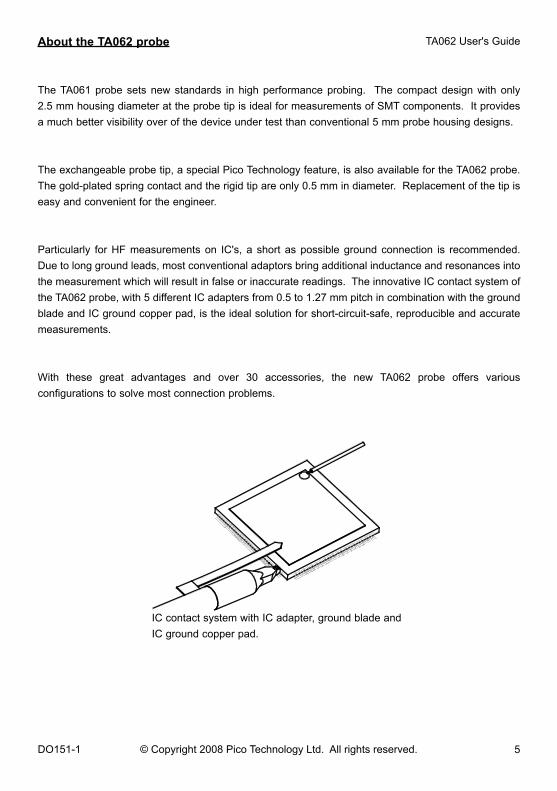
Particularly for HF measurements on IC's, a short as possible ground connection is recommended.
Due to long ground leads, most conventional adaptors bring additional inductance and resonances into
the measurement which will result in false or inaccurate readings. The innovative IC contact system of
the TA062 probe, with 5 different IC adapters from 0.5 to 1.27 mm pitch in combination with the ground
blade and IC ground copper pad, is the ideal solution for short-circuit-safe, reproducible and accurate
measurements.
With these great advantages and over 30 accessories, the new TA062 probe offers various
configurations to solve most connection problems.
IC contact system with IC adapter, ground blade and
IC ground copper pad.

6 DO151-1
TA062 User's Guide
© Copyright 2008 Pico Technology Ltd. All rights reserved.
Specifications
Specifications are typical and are published as general information for the user. The instrument
should have warmed up for at least 20 minutes and the environmental conditions must not exceed
the probe's specified limits.
Electrical specifications
Attenuation ratio (1) 10:1 ± 2 % at DC
System bandwidth 1.5 GHz (-3 dB)
Probe risetime 240 ps (10 % to 90 %) (typical)
Maximum rated input voltage 12 V DC incl. AC peak
Voltage derating
Note that the maximum input voltage
rating of the probe decreases as
the frequency of the applied
signal increases.
(1) Connect to oscilloscope with a input impedance of 50 Ω ± 1 %.
Typical voltage derating TA062
0
5
10
15
0.1 1 10 100 1000 10000
Frequency [MHz]
Am
pli
tud
e D
C i
ncl
. p
eak
AC
[V
] si
ne
7
TA062 User's Guide
DO151-1 © Copyright 2008 Pico Technology Ltd. All rights reserved.
Specifications
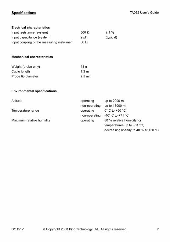
Electrical characteristics
Input resistance (system) 500 Ω ± 1 %
Input capacitance (system) 2 pF (typical)
Input coupling of the measuring instrument 50 Ω
Mechanical characteristics
Weight (probe only) 48 g
Cable length 1.3 m
Probe tip diameter 2.5 mm
Environmental specifications
Altitude operating up to 2000 m
non-operating up to 15000 m
Temperature range operating 0° C to +50 °C
non-operating -40° C to +71 °C
Maximum relative humidity operating 80 % relative humidity for
temperatures up to +31 °C,
decreasing linearly to 40 % at +50 °C
8 DO151-1
TA062 User's Guide
© Copyright 2008 Pico Technology Ltd. All rights reserved.
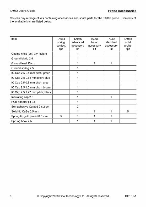
Probe Accessories
You can buy a range of kits containing accessories and spare parts for the TA062 probe. Contents of the available kits are listed below.
Item TA064 spring contact
tips
TA065 advanced accessory
kit
TA066 basic
accessory kit
TA067 standard
accessory kit
TA068solidprobetips
Coding rings (set) 3x4 colors 1
Ground blade 2.5 1
Ground lead 15 cm 1 1 1
Ground spring 2.5 1
IC-Cap 2.5 0.5 mm pitch; green 1
IC-Cap 2.5 0.65 mm pitch; blue 1
IC Cap 2.5 0.8 mm pitch; grey 1
IC Cap 2.5 1.0 mm pitch; brown 1
IC Cap 2.5 1.27 mm pitch; black 1
Insulating cap 2.5 1 1
PCB adapter kit 2.5 1
Self-adhesive Cu pad 2 x 2 cm 2
Solid tip CuBe 0.5 mm 1 1 1 5
Spring tip gold plated 0.5 mm 5 1 1 1
Sprung hook 2.5 1 1 1

9
TA062 User's Guide
DO151-1 © Copyright 2008 Pico Technology Ltd. All rights reserved.
Probe Accessories
IC-Cap 2.5
0.65 mm pitch; blue
IC-Cap 2.5
0.5 mm pitch; green
PCB Adapter Kit 2.5
BNC Adapter 2.5
Self-adhesiveCu Pads
( 2 x 2 cm )
Sprung Hook 2.5 - 50 ohmblack
Protection Cap 2.5
IC-Cap 2.5
0.8 mm pitch; gray
IC-Cap 2.5
1.0 mm pitch; brown
IC-Cap 2.5
1.27 mm pitch; black
Insulating Cap 2.5
Set 5 Solid TipsCuBe 0.5 mm
Set 5 Spring Tips gold-plated 0.5 mm
2-Footed Positioner
Probe
Ground Lead 15 cm
Ground Lead 11 cm
DEVICE UNDERTEST
Set Coding Rings
3x4 colors
Ground Blade 2.5
Ground Spring 2.5

10 DO151-1
TA062 User's Guide
© Copyright 2008 Pico Technology Ltd. All rights reserved.
Scope of delivery
The following items are included in the scope of delivery. Please check the delivery for
completeness. If any item is missing, send a message to our service department and we will send
you this item immediately.
Item Qty
Coding rings (set) 3x4 Colors 1
Ground blade 2.5 1
Ground lead 11 cm 1
Ground spring 2.5 1
IC-Cap 2.5 0.5 mm pitch; green 1
IC-Cap 2.5 0.65 mm pitch; blue 1
IC-Cap 2.5 0.8 mm pitch; grey 1
IC-Cap 2.5 1.0 mm pitch; brown 1
IC-Cap 2.5 1.27 mm pitch; black 1
User's Guide 1
Insulating cap 2.5 1
PCB Adapter kit 2.5 1
Probe 1
Protection Cap 2.5 1 (1)
Self-adhesive Cu pad (2 x 2 cm) 2
Solid tip CuBe 0.5 mm 1 Spring tip gold plated 0.5 mm 1 (2)
Sprung hook 2.5 1
2-footed positioner 1
(1) plugged on probe
(2) installed in probe
Use ground lead only for connections to earth ground.
The BNC Adapter is rated: 42 V pk AC + DC
The accessories provided with the probe have been safety tested.
Do not use any other accessories than those originally provided.
11
TA062 User's Guide
DO151-1 © Copyright 2008 Pico Technology Ltd. All rights reserved.
Handling
Handle the probe with care, especially when it is fitted with the extra thin and sharp
spring contact tip, to avoid any injury. Note that the probe cable is a sensitive part of the
probe. Do not damage through excessive bending or pulling. Avoid mechanical shock to
this product in general to guarantee accurate performance and protection.
Maintenance
Cleaning
To clean the exterior of the probe use a soft cloth moistened with either distilled water or isopropyl
alcohol. Before use allow the probe to dry completely.
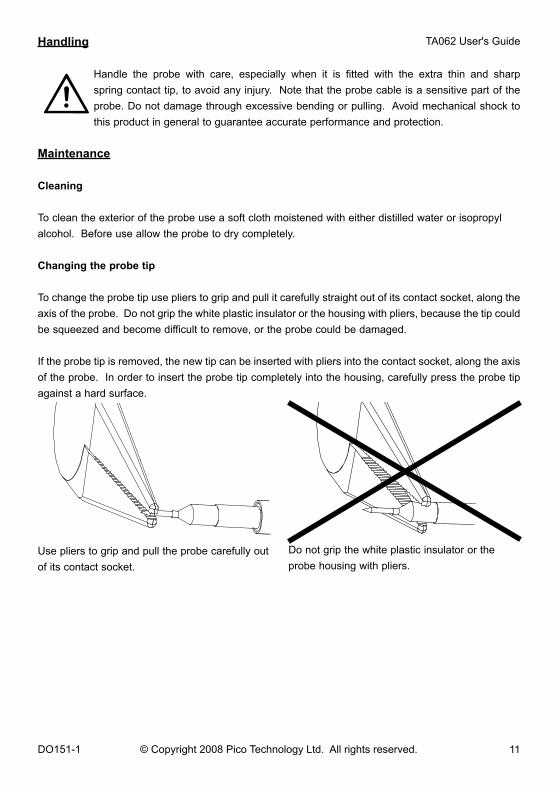
Changing the probe tip
To change the probe tip use pliers to grip and pull it carefully straight out of its contact socket, along the
axis of the probe. Do not grip the white plastic insulator or the housing with pliers, because the tip could
be squeezed and become difficult to remove, or the probe could be damaged.
If the probe tip is removed, the new tip can be inserted with pliers into the contact socket, along the axis
of the probe. In order to insert the probe tip completely into the housing, carefully press the probe tip
against a hard surface.
Use pliers to grip and pull the probe carefully out
of its contact socket.
Do not grip the white plastic insulator or the
probe housing with pliers.

DO151-1


