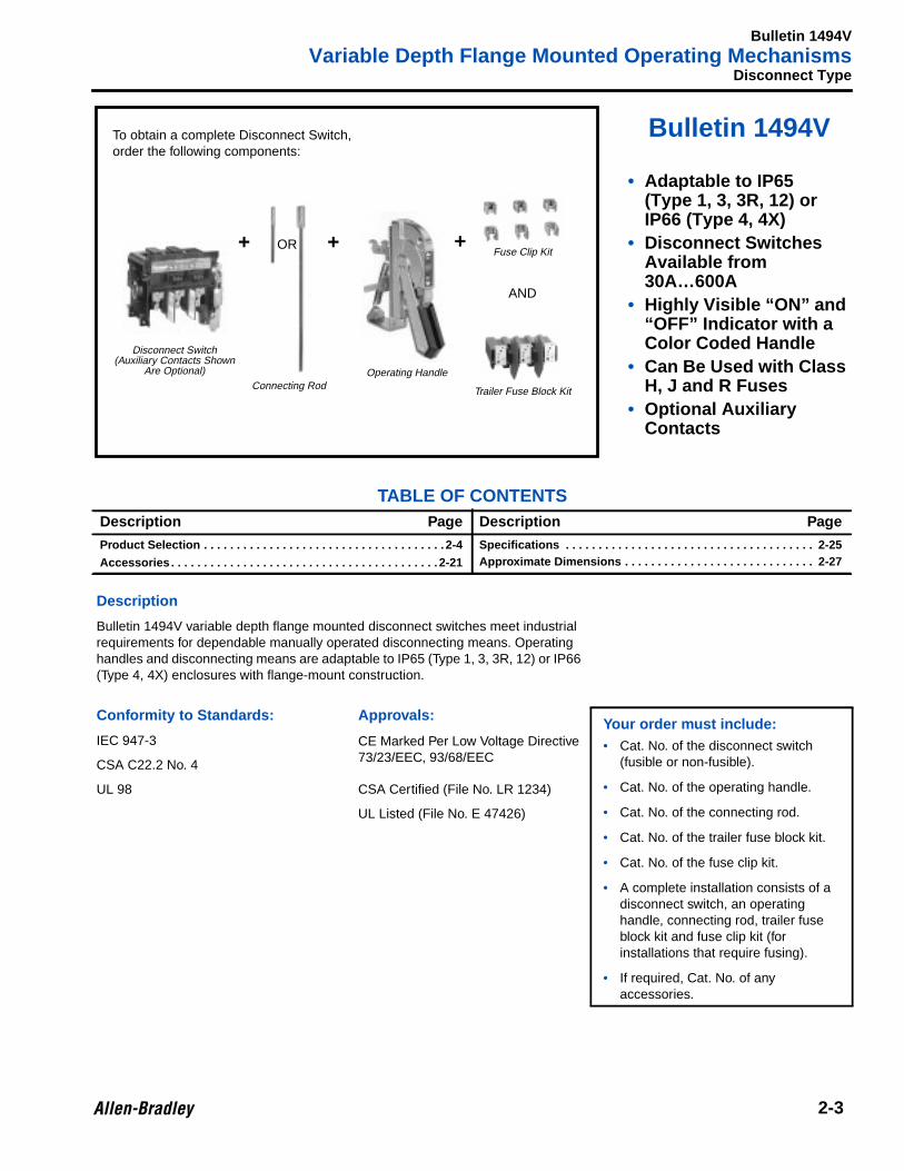
Bulletin 1494V variable depth flange mounted disconnect switches meet industrialrequirements for dependable manually operated disconnecting means. Operatinghandles and disconnecting means are adaptable to IP65 (Type 1, 3, 3R, 12) or IP66(Type 4, 4X) enclosures with flange-mount construction.
Conformity to Standards: Approvals:Your order must include:• Cat. No. of the disconnect switch
(fusible or non-fusible).
• Cat. No. of the operating handle.
• Cat. No. of the connecting rod.
• Cat. No. of the trailer fuse block kit.
• Cat. No. of the fuse clip kit.
• A complete installation consists of adisconnect switch, an operatinghandle, connecting rod, trailer fuseblock kit and fuse clip kit (forinstallations that require fusing).
• If required, Cat. No. of anyaccessories.
IEC 947-3 CE Marked Per Low Voltage Directive73/23/EEC, 93/68/EECCSA C22.2 No. 4
UL 98 CSA Certified (File No. LR 1234)
UL Listed (File No. E 47426)
To obtain a complete Disconnect Switch,order the following components:
Fusible Disconnect Switch Kits• Includes switch, connecting rod, handle, trailer fuse block and fuse clips
Non-Fusible Disconnect Switch Kits• Includes switch, connecting rod, handle (line and load lug connectors located in Accessories section)
➊ Ratings based on utilizing 2 poles in series to break one line of the DC supply voltage and the remaining pole breaking the second DC supply line.➋ Long Connecting Rods — Disconnect switch kits are also available with a long connecting rod. To order, add the letter “L” after the letter H,
N or R in the Cat. No.➌ 50 HP at 200V AC; 60HP at 208V AC.
Complete Disconnect Switch Kits for IP65 (Type 1, 3, 3R and 12) Enclosures
Size (A)
IEC ApplicationsMaximum kW
(AC23)
UL and CSAApplicationsMaximum HP
AC 1∅ DC ➊
FuseSize
FuseVolt.
FuseClips Cat. No. ➋ ❋
3∅, 50 Hz 3∅, 60 Hz
220 –240V
380 –440V
500 –600V 115V
200 –208V 230V 460V 575V 115V 230V 125V 250V
30 5.5 11 15 3 7.5 7.5 15 20 2 3 3 5 1…30A
250 H 1494V-DH233250 R 1494V-DR233600 H, J 1494V-DH633600 R 1494V-DR633
60 11 22 37 7.5 15 15 30 50 3 10 5 10 31…60A
250 H 1494V-DH266250 R 1494V-DR266600 H, J 1494V-DH666600 R 1494V-DR666
100 22 45 55 – 25 30 60 75 – – – 20 61…100A
250 H 1494V-DH611250 R 1494V-DR611600 H, J 1494V-DH611600 R 1494V-DR611
200 48 90 110 – ➌ 60 125 150 – – – 40 101…200A
250 H 1494V-DH622250 R 1494V-DR622600 H, J 1494V-DH622600 R 1494V-DR622
400 90 185 257 – 75 125 250 350 – – – 50 201…400A
250 H 1494V-DH644250 R 1494V-DR644600 H, J 1494V-DH644600 R 1494V-DR644
Connecting RodsApproximate dimensions are in millimeters (inches). Approximate dimensions are not intended for manufacturing purposes.
Operating Handles
➊ Also rated operational current for utilization categories AC-20 and AC-21 (IEC 408). For 1∅ ratings or other AC or DC utilization categories,consult Allen-Bradley Sales Office.
➋ Ratings based on utilizing 2 poles in series to break one line of the DC supply voltage and the remaining pole breaking the second DC supply line.➌ Devices are field convertible from right hand to left hand flange operation.➍ Connecting Rods and Operating Handles must be ordered separately.➎ 50 HP at 200V AC; 60 HP at 208V AC.➏ Enclosure depth is measured from the top of the flange to the disconnect means mounting surface (mm).➐ Two per installation required.
Variable Depth Flange Mounted Operating MechanismsProduct Selection, Continued
Fuse Clip Kits• Includes six clips and mounting hardware
Trailer Fuse Block KitsFor Class H and J fuses, select the proper fuse clip kit from the table above. For UL Class R fuse applications, non-removablerejection type clips are mounted on the trailer fuse block at the factory. Three additional clips are included for mounting on thedisconnect switch.
➊ Not required when installing 201 through 400A fuses on the 200A disconnect switch, Cat. No. 1494V-DS200 .➋ Down Fusing — For all Class H and J applications, order the Trailer Fuse Block kit for the size disconnect being used and order the lower
ampacity Fuse Clip Kit. Note: The 100A disconnect size requires that an Adapter Kit, Cat. No. 1401-N170 also be ordered. For Class Rapplications, refer to the trailer fuse block kit table above for listed devices.
➌ For use with Class J fuses only.➍ Single Pole Fuse Block — 3 required per installation.
Circuit Breaker Type, ContinuedCircuit Breaker Operating Mechanism — The mechanism listed must be combined with a connecting rod, operating handle andcircuit breaker to obtain a functional device.
Connecting RodsApproximate dimensions are in millimeters (inches). Approximate dimensions are not intended for manufacturing purposes.
Operating Handle
➊ Circuit breakers to be provided by user.
3-Pole Circuit Breaker ➊ Operating Mechanism
Manufacturer Size (A) Frame DesignationRight Hand
Cat. No.Left HandCat. No. ❋
Cutler-Hammer/Westinghouse
150EHD, FD, FDB, FDC,
HFD, HMCP1494V-M40 1494V-M40
Cutler-Hammer/Westinghouse
250JD, JDB, JDC,HJD, HMCP
1494V-M50 1494V-M50
400KD, KDB, KDC,
HKD, HMCP1494V-M60 1494V-M60
Circuit BreakerFrame Size (A)
Enclosure Depth
Cat. No. ❋Minimum Maximum
150, 250 and 400172 (6-3/4) 232 (9-1/8) 1494V-RA1
232 (9-1/8) 585 (23) 1494V-RA2
Enclosure Type MountingCircuit BreakerFrame Size (A)
Remote Handling Mechanisms — Allow the operating handle to be mounted eitherabove or below the disconnect means.
Dual Operating Mechanisms — Permit the control of two disconnect means utilizinga common operating handle.
Operation — Both the Remote and Dual Operating Mechanisms consist of twocomponents — a main drive mechanism (which includes the operating handle) anda remote drive mechanism. To obtain a functional device, these components mustbe properly combined with a connecting link (supplied by customer), disconnectmeans and connecting rod.
Conformity to Standards: Approvals:Your order must include:• Cat. No. of the remote driver or main
Remote or Dual Operated Mechanisms — Separate Components
➊ Includes Main and Remote Drive Mechanisms. Does not include rectangular bar stock (1/4-inch) 6.35mm x (5/8-inch) 15.8mm connecting barbetween disconnecting means and connecting rod, to be supplied by user.
Bulletin 1494F Fixed-Depth Flange Mounted Disconnect Switches meet industrialrequirements for a dependable manually operated disconnecting means. The FusibleDisconnect Switch Assembly is made up of two components — a Disconnect Switchand Operating Mechanism and a Fuse Block Adapter Kit, with fuse clips.
Conformity to Standards: Approvals:Your order must include:• Cat. No. of the disconnect switch
fusible or non-fusible.
• Cat. No. of the Fuse Block AdapterPlate Kit with fuse clips.
• To obtain a complete fusibledisconnect switch the above itemsmust be on your order.
• Accessories, if necessary.
IEC 947-3 CE Marked Per Low Voltage Directive73/23/EEC, 93/68/EEC
CSA C22.2 No. 4
UL 98 CSA Certified (File No. LR 1234)
UL Listed (File No. E 47426)
To obtain a complete Fusible Disconnect Switch,order the following components:
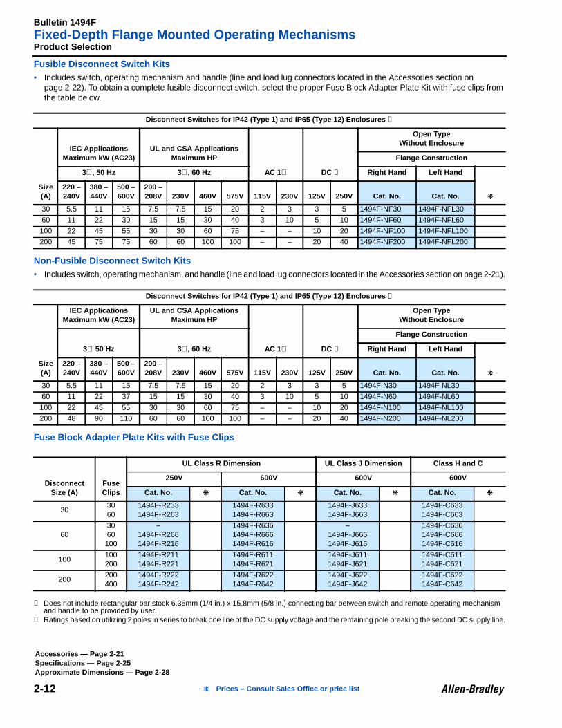
Fusible Disconnect Switch Kits• Includes switch, operating mechanism and handle (line and load lug connectors located in the Accessories section on
page 2-22). To obtain a complete fusible disconnect switch, select the proper Fuse Block Adapter Plate Kit with fuse clips fromthe table below.
Non-Fusible Disconnect Switch Kits• Includes switch, operating mechanism, and handle (line and load lug connectors located in the Accessories section on page 2-21).
Fuse Block Adapter Plate Kits with Fuse Clips
➊ Does not include rectangular bar stock 6.35mm (1/4 in.) x 15.8mm (5/8 in.) connecting bar between switch and remote operating mechanismand handle to be provided by user.
➋ Ratings based on utilizing 2 poles in series to break one line of the DC supply voltage and the remaining pole breaking the second DC supply line.
Disconnect Switches for IP42 (Type 1) and IP65 (Type 12) Enclosures ➊
Bulletin 1494F line of NEMA enclosed disconnect switches are compact in size, butruggedly designed for long lasting performance. These switches are ideal for use as:• “At Motor” disconnect• “Main” safety switch
Your order must include:• Cat. No. of the disconnect switch
(fusible or non-fusible).
• Cat. No. of the Fuse Block AdapterPlate Kit with fuse clips.
• To obtain a complete fusibledisconnect switch the above itemsmust be on your order.
Bulletin 1494D Fixed Depth Circuit Breaker Operating Mechanisms are designed tooperate commonly used molded case circuit breakers (which are to be supplied bythe user).
Conformity to Standards: Approvals:Your order must include:• Cat. No. of the operating mechanism.
• Cat. No. of the slide or bail mechanism.
• Cat. No. of any accessories, ifrequired.
• An operating mechanism and a slide orbail mechanism must be combinedwith the proper circuit breaker in orderto obtain a functional device.
IEC 947-3 CSA Certified (File No. LR 1234)
CSA C22.2 No. 4 UL Listed (File No. E 47426)
UL 98
Cat. No. 1494D-N4 and Cat. No. 1494D-N40(Circuit Breaker Not Included. Auxiliary Contact and
Adapter Kit Must Be Ordered Separately)
To obtain a complete operating mechanism, order anOperating Mechanism and Slide or Bail Mechanism.
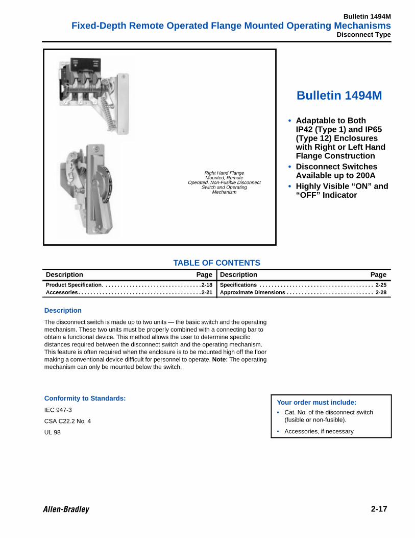
The disconnect switch is made up to two units — the basic switch and the operatingmechanism. These two units must be properly combined with a connecting bar toobtain a functional device. This method allows the user to determine specificdistances required between the disconnect switch and the operating mechanism.This feature is often required when the enclosure is to be mounted high off the floormaking a conventional device difficult for personnel to operate. Note: The operatingmechanism can only be mounted below the switch.
Conformity to Standards:Your order must include:• Cat. No. of the disconnect switch
(fusible or non-fusible).
• Accessories, if necessary.
IEC 947-3
CSA C22.2 No. 4
UL 98
Right Hand FlangeMounted, Remote
Operated, Non-Fusible DisconnectSwitch and Operating
Fusible Disconnect Kits• Includes switch, fuse block adapter plate, fuse clips, operating mechanism and handle (line and load lug connectors located in
the Accessories section on page 2-22).
Non-Fusible Disconnect Kits• Includes switch, operating mechanism and handle (line and load lug connectors located in the Accessories section on page 2-22).
Fuse Block Adapter Plate Kits with Fuse Clips
➊ Does not include rectangular bar stock 6.35mm (1/4 in.) x 15.8mm (5/8 in.) connecting bar between switch and remote operating mechanismand handle to be provided by user.
➋ Ratings based on utilizing 2 poles in series to break one line of the DC supply voltage and the remaining pole breaking the second DC supply line.
Complete Disconnect Switch Kit for IP42 (Type 1) and IP65 (Type 12) ➊
Bulletin 1494R rod operated disconnect switch is applicable to both IP42 (Type 1)and manual type disconnect device. The complete Disconnect Switch consists of thedisconnect switch, operating handle, connecting rod and hitch pin.
Conformity to Standards: Approvals:Your order must include:• Cat. No. of the disconnect switch.
• If necessary, Cat. No. of anyaccessories.
IEC 947-3 CSA Certified (File No. LR 1234)
CSA C22.2 No. 4 UL Listed (File No. E 47418)
UL 98
Disconnect Switch(Auxiliary Contact Shown is Optional)
OperatingHandle
ConnectingRod andHitch Pin
+ +
To obtain a complete Disconnect Switch Kit, order the following:
Cat. No. 1494R-N30
2-19
Bulletin 1494R
Variable Depth Door Mounted Operating MechanismsProduct Selection
Disconnect Switch Kits• Includes switch, operating handle, connecting rod and hitch pin (line and load lug connectors located in the Accessories section
on page 2-22).
Longer Shafts — Approximate dimensions are in mm (inches)The standard lengths for shafts furnished with the disconnect switches are 241.3 (9-1/2) on the 30A and 60A and 279.4 (11) on the100A and 200A. Longer shafts are available and must be ordered separately. Approximate dimensions are not intended formanufacturing purposes.
➊ Ratings based on utilizing 2 poles in series to break one line of the DC supply voltage and the remaining pole breaking the second DC supply line.➋ To obtain a fusible disconnect switch, add Bulletin 1491 fuse blocks. See page 2-30.
Complete Non-Fused Disconnect Switch Kits for IP42 (Type 1) and IP65 (Type 12) Enclosures
2-20 ❋ Prices – Consult Sales Office or price list
Bulletin 1494
Accessories — Field Installed
2 Accessories
➊ Requires an adapter kit on new installations.➋ One auxiliary contact adapter kit enables up to two auxiliary contacts to be installed.➌ Required on new installations only.
Auxiliary Contact Adapter Kit250A and 400A Frame Cutler-Hammer/Westinghouse
1494VCircuit Breaker
1495-N23
Auxiliary Contacts1 N.O. Contact
1494VDisconnect Switch
595-A
Auxiliary Contacts1 N.C. Contact
1494VDisconnect Switch
595-B
Auxiliary Contact Adapter Kit400A and 600A Disconnect
1494VDisconnect Switch
595-N1
Auxiliary Contacts1 N.O. Contact
1494RDisconnect
Switch30, 60A
895-A1
Auxiliary Contacts1 N.C. Contact
895-B1
Auxiliary Contacts1 N.O. and 1 N.C. Contact
895-C1
Auxiliary Contact Adapter Kitfor 1 contact
895-M11
Auxiliary Contact Adapter Kitfor 2 contacts
895-M12
Auxiliary Contacts1 N.O. Contact
1494RDisconnect
Switch100, 200A
895-A2
Auxiliary Contacts1 N.C. Contact
895-B2
Auxiliary Contacts1 N.O. and 1 N.C. Contact
895-C2
Auxiliary Contact Adapter Kitfor 1 contact
895-M21
Auxiliary Contact Adapter Kitfor 2 contacts
895-M22
Auxiliary Contact1 N.O. Contact
1494FEnclosed
DisconnectsOnly
1495-N30
Auxiliary Contact1 N.C. Contact
1495-N31
Auxiliary Contact Adapter Kit ➌
(for a maximum of 2 contacts)1495-N32
Auxiliary Contact1 N.O. Contact and 1 N.C. Contact early break
1495-N33
Cat. No.1495-N21
Cat. No.1495-N23
Cat. No. 595-A Cat. No. 595-B
Cat. No. 895-A1
Cat. No. 895-M11
Cat. No. 895-M21
Cat. No. 895-A2
Cat. No.1495-N30
Cat. No.1495-N31
Cat. No.1495-N32
Cat. No.1494F-N33
2-21❋ Prices – Consult Sales Office or price list
Bulletin 1494
Accessories — Field InstalledAccessories, Continued
➊ All terminals of the 30A switches are furnished with self-lifting pressure plate connectors as standard.
DescriptionFor use with
Cat. No. Cat. No. ❋
Lug Connectors (3 per package)
1494V, 1494F,1494M, 1494R
DisconnectSwitches
DisconnectSize (A)
Wire Size
30 #14…#8 AWG Wire ➊
60 #14…#4 AWG Wire 1494R-N1
100 #8…#1/0 AWG Wire 1494R-N2
200 #6…#4/0 AWG Wire 1494R-N3
400…600 2 of #110…350 MCM Wire 1494R-N10
Defeater Bracket Extension KitFor use with operating handles that do not align properlywith the door catch or door hardware on enclosures with arolled lip flange construction.
All 1494V handles(except 1494V-R1
and 1494V-R2)1494V-H12
Alternate Mounting KitsFor use where the flange material thickness is greater than4.8mm (3/16 in.).
Operating handles1494V-H1 or1494V-H11
1494V-H3
Operating Han-dles 1494V-H2
1494V-H6
Channel Support KitsFor use to prevent flexing of the operating handle mountingsurface. This is especially useful when the operating handleis mounted on a channel in a multi-door enclosure.
Applies only tooperating handleCat. Nos. 1494V-H1, W1, H11 and
W11 (does notapply to dual or
remote operators).
1494V-H4
Cat. No. 1494R-N3
Cat. No. 1494R-H3
2-22 ❋ Prices – Consult Sales Office or price list
Bulletin 1494
Accessories — Field Installed
Accessories, Continued
DescriptionFor use with
Cat. No. Cat. No. ❋
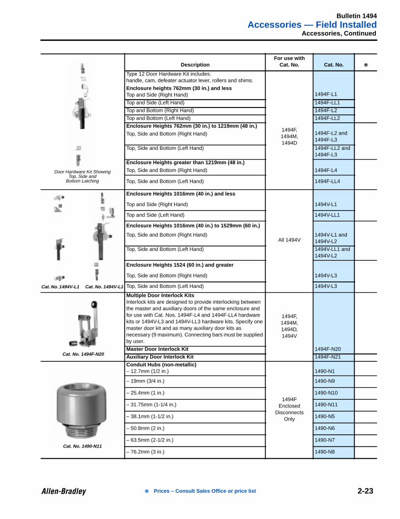
Type 12 Door Hardware Kit includes:handle, cam, defeater actuator lever, rollers and shims.
1494F-L1Enclosure heights 762mm (30 in.) and lessTop and Side (Right Hand)
1494F,1494M,1494D
Top and Side (Left Hand) 1494F-LL1
Top and Bottom (Right Hand) 1494F-L2
Top and Bottom (Left Hand) 1494F-LL2
Enclosure Heights 762mm (30 in.) to 1219mm (48 in.)1494F-L2 and1494F-L3
Top, Side and Bottom (Right Hand)
Top, Side and Bottom (Left Hand) 1494F-LL2 and1494F-L3
Enclosure Heights greater than 1219mm (48 in.)Top, Side and Bottom (Right Hand) 1494F-L4
Top, Side and Bottom (Left Hand) 1494F-LL4
Enclosure Heights 1016mm (40 in.) and less
All 1494V
Top and Side (Right Hand) 1494V-L1
Top and Side (Left Hand) 1494V-LL1
Enclosure Heights 1016mm (40 in.) to 1529mm (60 in.)
Top, Side and Bottom (Right Hand) 1494V-L1 and1494V-L2
Top, Side and Bottom (Left Hand) 1494V-LL1 and1494V-L2
Enclosure Heights 1524 (60 in.) and greater
Top, Side and Bottom (Right Hand) 1494V-L3
Top, Side and Bottom (Left Hand) 1494V-L3
Multiple Door Interlock KitsInterlock kits are designed to provide interlocking betweenthe master and auxiliary doors of the same enclosure andfor use with Cat. Nos. 1494F-L4 and 1494F-LL4 hardwarekits or 1494V-L3 and 1494V-LL3 hardware kits. Specify onemaster door kit and as many auxiliary door kits asnecessary (9 maximum). Connecting bars must be suppliedby user.
1494F,1494M,1494D,1494V
Master Door Interlock Kit 1494F-N20
Auxiliary Door Interlock Kit 1494F-N21
Conduit Hubs (non-metallic)– 12.7mm (1/2 in.)
1494FEnclosed
DisconnectsOnly
1490-N1
– 19mm (3/4 in.) 1490-N9
– 25.4mm (1 in.) 1490-N10
– 31.75mm (1-1/4 in.) 1490-N11
– 38.1mm (1-1/2 in.) 1490-N5
– 50.8mm (2 in.) 1490-N6
– 63.5mm (2-1/2 in.) 1490-N7
– 76.2mm (3 in.) 1490-N8
Door Hardware Kit ShowingTop, Side and
Bottom Latching
Cat. No. 1494V-L1 Cat. No. 1494V-L 3
Cat. No. 1494F-N20
Cat. No. 1490-N11
2-23❋ Prices – Consult Sales Office or price list
Bulletin 1494Modifications — Factory Installed
2-24
2Modifications
Bulletin 1494F Enclosed Disconnect Switches
➊ Only one push button or pilot light may be added to a Bulletin 1494F Disconnect Switch.➋ A maximum of two auxiliary contacts may be added to a Bulletin 1494F Disconnect Switch.
DescriptionFor use with
Cat. No. Suffix Code ❋
Signal Push Button (1 N.O.) ➊
1494F
EnclosedDisconnects
Only
-1S
Red Pilot Light ➊ -4R
Green Pilot Light ➊ -4G
Red Push to Test Pilot Light ➊ -5R
Auxiliary Contact (1 N.O.) ➋ -98
Auxiliary Contact (1 N.C.) ➋ -99
Enclosure Door Viewing Window -203W
❋ Prices – Consult Sales Office or price list
Bulletin 1494Disconnect Switches
2-25
2 Specifications
1494F Disconnect, 1494M Remote Type, 1494V Disconnect Type,1494V Remote or Dual Type, 1494R Disconnect Type
Bulletin 1494Disconnect Switches and Circuit Breakers
2-27
2 Approximate Dimensions
Bulletin 1494VDimensions are shown in millimeters (inches). Dimensions are not intended for manufacturing purposes.
➊ Approximate dimensions are for reference only.➋ This approximate dimension will vary by fuse class and size.➌ Approximate dimension with Class J fuses.
Disconnect Switches ➊
NEMA Size(A) A
B ➋ C
D E FMax Min Max
306-19/64(160)
202(7-31/32)
171(6-3/4)
549(21-5/8)
69.9(2-3/4)
192(7-9/16)
98.5(3-7/8)
606-19/64(160)
215(8-15/32)
171(6-3/4)
549(21-5/8)
65.1(2-9/16)
192(7-9/16)
98.5(3-7/8)
1006-19/64(160)
231.8(9-1/8)
171(6-3/4)
599(28-5/8)
90.9(3-37/64)
192(7-9/16)
98.5(3-7/8)
2008-5/64(205.2)
384.5(15-9/64)
197(7-3/4)
549(21-5/8)
166.3(6-35/64)
223(8-25/32)
118(4-21/32)
40015-23/32(399.2)
479.2(18-7/32)
193.7(7-5/8)
549(21-5/8)
203.2(8)
300.8(11-27/32)
223.3(8-51/64)
60015-23/32(399.2)
446.8(17-19/32) ➌
193.7(7-5/8)
549(21-5/8)
304.8(12)
300.8(11-27/32)
223.3(8-51/64)
Circuit Breakers ➊
Frame A B
C
D E FMin Max150AEHD, FD, FDB, FDC, HFD, HMCP
152.4(6)
–171.5(6-3/4)
584.2(23)
152.4(6)
138.1(5-7/16)
127(5)
250AJD, JDB, JDC, HJD, HMCP
285.8(11-1/4)
–200.0(7-7/8)
573.1(22-9/16)
254(10)
145.2(5-23/32)
246.8(9-23/32)
400AKD, KDB, KDC, HKD, HMCP
228.9(11-3/8)
–200.0(7-7/8)
573.1(22-9/16)
304.8(12)
181.0(7-1/8)
245.3(9-21/32)
CircuitBreakerAuxiliaryWhen Used
Common IndustrialFlange Cut-Out
Trailer Fuse Block
Vertical Center Line of Operating Handle DrillingDoor
Bulletin 1494F, 1494MDimensions are shown in millimeters (inches). Dimensions are not intended for manufacturing purposes.
Bulletin 1494D
➊ Minimum wiring space for the maximum wire size.➋ Approximate dimensions are for reference only.➌ This approximate dimension will vary by fuse class and size.
Circuit Breakers ➋
Cutler-Hammer/Westinghouse Frame A B ➌
C
D E FMin Max150AEHD, FD, FDB, FDC, HFD, HMCP
198.4(7-13/16) – 161.9
(6-3/8) – 152.4(6)
142.9(5-5/8)
163.5(6-7/16)
250AJD, JDB, JDC, HJD, HMCP
292.1(11-1/2) – 212.7
(8-3/8) – 203.2(8)
147.6(5-13/16)
239.7(9-7/16)
400AKD, KDB, KDC, HKD, HMCP
292.1(11-1/2) – 212.7
(8-3/8) – 304.8(12)
174.6(6-7/8)
239.7(9-7/16)
600ALA, HLA, LC, HLC, LD, HLD
288.9(11-3/8) – 241.3
(9-1/2) – 203.2(8)
304.8(12)
267.5(10-17/32)
800AMA, HMA, MC, ND, HND, NDC
406.4(16) – 241.3
(9-1/2) – 254(10)
312.7(12-5/16)
183.4(15-3/32)
800ANB TRI-PAK
558.8(22) – 241.3
(9-1/2) – 254(10)
312.7(12-5/16)
535.8(21-3/32)
1200ANB, HNB, NC, HNC, ND, HND, NDC
406.4(16) – 241.3
(9-1/2) – 304.8(12)
312.7(12-5/16)
183.4(25-3/32)
H
S
L
KF
D
PDoor Catch
MIN.
Disconnect Switch
NEMASize(A) D F H K L P S ➊
Without Door Hardware
30 30.2(1-3/16)
36.5(1-7/16)
215.9(8-1/2)
11.9(15/32)
182.6(7-3/16)
54(2-1/8)
52.4(2-1/16)
60 30.2(1-3/16)
36.5(1-7/16)
215.9(8-1/2)
11.9(15/32)
182.6(7-3/16)
54(2-1/8)
82.6(3-1/4)
100 30.2(1-3/16)
36.5(1-7/16)
215.9(8-1/2)
11.9(15/32)
182.6(7-3/16)
54(2-1/8)
206.8(8-9/64)
200 31.8(1-1/4)
42.9(1-11/16)
282.6(11-1/8)
20.6(13/16)
241.3(9-1/2)
57.9(2-9/32)
264.3(10-13/32)
Small and Intermediate Enclosures with Door Hardware
30 30.2(1-3/16)
36.5(1-7/16)
215.9(8-1/2)
11.9(15/32)
182.6(7-3/16)
54.8(2-5/32)
57.2(2-1/4)
60 30.2(1-3/16)
36.5(1-7/16)
215.9(8-1/2)
11.9(15/32)
182.6(7-3/16)
54.8(2-5/32)
82.6(3-1/4)
100 30.2(1-3/16)
36.5(1-7/16)
215.9(8-1/2)
11.9(15/32)
182.6(7-3/16)
54.8(2-5/32)
206.8(8-9/64)
200 31.8(1-1/4)
42.9(1-11/16)
282.6(11-1/8)
20.6(13/16)
241.3(9-1/2)
58.7(2-5/16)
264.3(10-13/32)
Large Enclosures with Door Hardware
30 30.2(1-3/16)
36.5(1-7/16)
215.9(8-1/2)
11.9(15/32)
182.6(7-3/16)
57.2(2-1/4)
69.9(2-3/4)
60 30.2(1-3/16)
36.5(1-7/16)
215.9(8-1/2)
11.9(15/32)
182.6(7-3/16)
57.2(2-1/4)
82.6(3-1/4)
100 30.2(1-3/16)
36.5(1-7/16)
215.9(8-1/2)
11.9(15/32)
182.6(7-3/16)
57.2(2-1/4)
206.8(8-9/64)
200 31.8(1-1/4)
42.9(1-11/16)
282.6(11-1/8)
20.6(13/16)
241.3(9-1/2)
59.5(2-11/32)
264.3(10-13/32)
Flange Cut-Out
CircuitBreakerAuxiliaryWhen Used
Common IndustrialFlange Cut-Out
Trailer Fuse Block
Vertical Center Line of Operating Handle DrillingDoor
Provides forWire BendingSpace
DisconnectingMeans
OperatingHandleMountingSurface
Disconnect MeansMounting Surface
EnclosureFlange
A
B
C
DE
F
Disconnect Switches ➋
NEMA Size(A) A B ➌
C
D E FMin Max
30 150.8(5-15/16)
273.1(10-3/4)
161.9(6-3/8) – 55.6
(2-3/16)190.5(7-1/2)
95.3(3-3/4)
60 150.8(5-15/16)
335(13-3/16)
161.9(6-3/8) – 50.8
(2)190.5(7-1/2)
95.3(3-3/4)
100 200.4(7-15/16)
425.5(16-3/4)
215.9(8-1/2) – 127
(5)209.6(8-1/4)
95.3(3-3/4)
200 266.7(10-1/2)
528.6(20-13/16)
228.6(9) – 177.8
(7)289
(11-3/8)141.3
(5-9/16)
Bulletin 1494Enclosed Disconnects
2-29
2 Approximate Dimensions, Continued
Bulletin 1494FDimensions are shown in millimeters (inches). Dimensions are not intended for manufacturing purposes.
Disc. Size(A) DIM Ref. A B C D E F G H J
30 A11228.6
(9)228.6
(9)28.2
(1-7/64)254(10)
82.5(3-1/4)
165.1(6-1/2)
63.5(2-1/2)
102.8(4-3/64)
9/32(7.1)
60 & 100 A12330.2(13)
228.6(9)
28.2(1-7/64)
355.6(14)
82.5(3-1/4)
165.1(6-1/2)
63.5(2-1/2)
102.8(4-3/64)
9/32(7.1)
200 A13533.4(21)
266.7(10-1/2)
28.2(1-7/64)
558(22)
101.6(4)
203.2(8)
63.5(2-1/2)
124.6(4-29/32)
9/32(7.1)
400 A14685.8(27)
355.6(14)
28.2(1-7/64)
685.8(27)
152.4(6)
228.6(9)
87.3(3-7/16)
186.5(7-11/32)
8.7(11/32)
Ampere Rating (A)
Wire Size
Line and Load Terminals Ground Terminal
30 #14…#6 AWG Wire (2) #10…#4 AWG Wire
60 #14…#4 AWG Wire (2) #10…#4 AWG Wire
100 #8…#1/0 AWG Wire (2) #10…#4 AWG Wire
200 #6…#4/0 AWG Wire (2) #6…#4/0 AWG Wire
400 (2) #1/0 AWG - 250 kcmil (2) #6…#4/0 AWG Wire
A
B
C
D
E
J Mounting Hole
G
H
F
Bulletin 1491
Fuse Blocks2
Bulletin 1491
• Fuse Blocks• Available from
30A…600A• Can be used with
Class H, J and R fuses
TABLE OF CONTENTSDescription Page Description Page
These Bulletin 1491 Fuse Blocks have been designed for general purposeapplications. The bases of these blocks, either phenolic or porcelain, are rugged inconstruction and provide ease in mounting and wiring.
Conformity to Standards: App rovals:
NEMA 512 CSA Certified (File No. LR 1234)
UL Listed (File No. E 34648)
30A Fuse BlocksWith Spring-Type Fuse Clips
and Self-Lifting Wiring Terminal Clamps
30A Fuse BlocksWith Spring-Type Fuse ClipsClass R Rejection Feature
➊ These fuse blocks have porcelain bases.➋ For two pole applications use two of Cat. No. 1491-N321 .➌ For two pole applications use two of Cat. No. 1491-N421 .➍ For two pole applications use two of Cat. No. 1491-N521 .➎ For three pole applications use three of Cat. No. 1491-N521 .➏ For two pole applications use two of Cat. No. 1491-N621 .➐ For three pole applications use three of Cat. No. 1491-N621 .➑ For two pole applications use two of Cat. No. 1491-R621 .➒ For three pole applications use three of Cat. No. 1491-R621 .
Dimensions are shown in millimeters (inches). Dimensions are not intended for manufacturing purposes.
➊ Alternate Mounting Holes.➋ Dimension “A” must be held to insure fuse block rejection function.
Notes:1. When fuse blocks are installed in a vertical plane, the block with the rejection numbers must be on the bottom.2. When using Cat. No. 1491-N321 , install fiber washers between fuse blocks and mounting plates. Discard extra screws, washers and clamps on
Fuse Size 101…200ADimensions are shown in millimeters (inches). Dimensions are not intended for manufacturing purposes.
➊ Dimension “A” must be held to insure fuse block rejection function.Note: When fuse blocks are installed in a vertical plane, the block with the rejection numbers must be on the bottom.
Voltage (V)
Class H or R Class J
A B A B250 120.7 (4-3/4) 228.6 (9) – –600 125.8 (4-61/64) 304.80 (12) 117.5 (4-5/8) 190.5 (7-1/2)
Rejection Members
Drill and Tap For 5/16-18 Screws
A
B
15.08 max.(19/32 Max.)
69.85(2-3/4)
222.25(8-3/4)
34.92(1-3/8)
34.92(1-3/8)
101…200A, 250…600VCat. No. 1491-R433
Shipping Weight — 3.2kg (7 lb)
Fuse Size(A)
MaximumVolts (V) Cat. No.
A ➊
±0.020B
Ref.
101…200250
1491-R433184.15 (7.25) 106.36 (4-3/16)
600 247.60 (9.75) 109.54 (4-5/16)
A B
50.80(2)
28.57(1-1/8)
50.80(2)
82.55(3-1/4)
101.60(4)
9.52(3/8)
9.52(3/8)
Drill For 5/16" -18 Screw
A B
50.80(2)
28.57(1-1/8)
50.80(2)
82.55(3-1/4)
317.50(12-1/2)
9.52(3/8)
9.52(3/8)
82.55(3-1/4)
82.55(3-1/4)
Drill For 5/16" -18 Screw
A B
50.80(2)
28.57(1-1/8)
50.80(2)
82.55(3-1/4)
425.45(16-3/4)
9.52(3/8)
9.52(3/8)
82.55(3-1/4)
82.55(3-1/4)
82.55(3-1/4)
Drill For 5/16" -18 Screw
A B
50.80(2)
28.57(1-1/8)
50.80(2)
82.55(3-1/4)
209.6(8-1/4)
9.52(3/8)
9.52(3/8)
82.55(3-1/4)
Drill For 5/16" -18 Screw
Single PoleCat. No. 1491-N521
Shipping Weight — 3.2kg (7lb)
2-Pole ApplicationUse Two of Cat. No. 1491-N521Shipping Weight — 6kg (13 lb)
3-Pole ApplicationUse Three of Cat. No. 1491-N521Shipping Weight — 8.6kg (19 lb)
4-Pole ApplicationUse Four of Cat. No. 1491-N521Shipping Weight — 11.4kg (25 lb)
2-36
Bulletin 1491
Fuse Blocks
Approximate Dimensions, Continued
Fuse Size 201…400ADimensions are shown in millimeters (inches). Dimensions are not intended for manufacturing purposes.
Fuse Size 401…600A
➊ Dimension “A” must be held to insure fuse block rejection function.
Notes:
1. When fuse blocks are installed in a vertical plane, the block with the rejection numbers must be on the bottom.
2. Fuse blocks with wedge type clamps (61A and above) can be oriented to mount all fuses either to the left or to the right of fuse clamp centers.