44

1
TABLE OF CONTENTS SECTION 1 - PLANT LOCATION County Township Range Section Identifiable Points SECTION 2 - ORGANIZATIONAL STRUCTURE Management Representatives Certified Aggregate Technicians SECTION 3 - MINERAL DEPOSITS List Description Quality Class Processing, Handling and Stockpiling Procedures SECTION 4 - AP AGGREGATE SECTION 5 - MATERIAL CATEGORIES Standard Specifications Alternate SECTION 6 - PRODUCTION FLOW DIAGRAM SECTION 7 - SAMPLING PLAN Frequency and Means of Tracking Locations Sampling Devices and Techniques SECTION 8 - TESTING PLAN Gradation Decantation Crushed Particles Deleterious Material Non-Conforming Materials SECTION 9 - GRADATION CONTROL Critical Sieves Target Mean Values Standard Deviations SECTION 10 - PROCESS CONTROL TECHNIQUES

2
SECTION 11 - DOWNSTREAM CONTROL Identification of Stockpiles Stockpile Construction Material Retrieval SECTION 12 - LABORATORY Location Equipment Calibration SECTION 13 - DOCUMENTATION PLAN Reference Documents Diary Test Data Control Charts Material Shipment Record SECTION 14 - ADDENDA APPENDIX A - AP PRODUCTION CONTROL PLAN APPENDIX B - GENERAL INFORMATION Location Map - General Stockpile Map Pit Area Maps APPENDIX C - FORMS Daily Diary Gradation Analysis Form Control Chart Shipping Record Form AUTHENTICATION
3
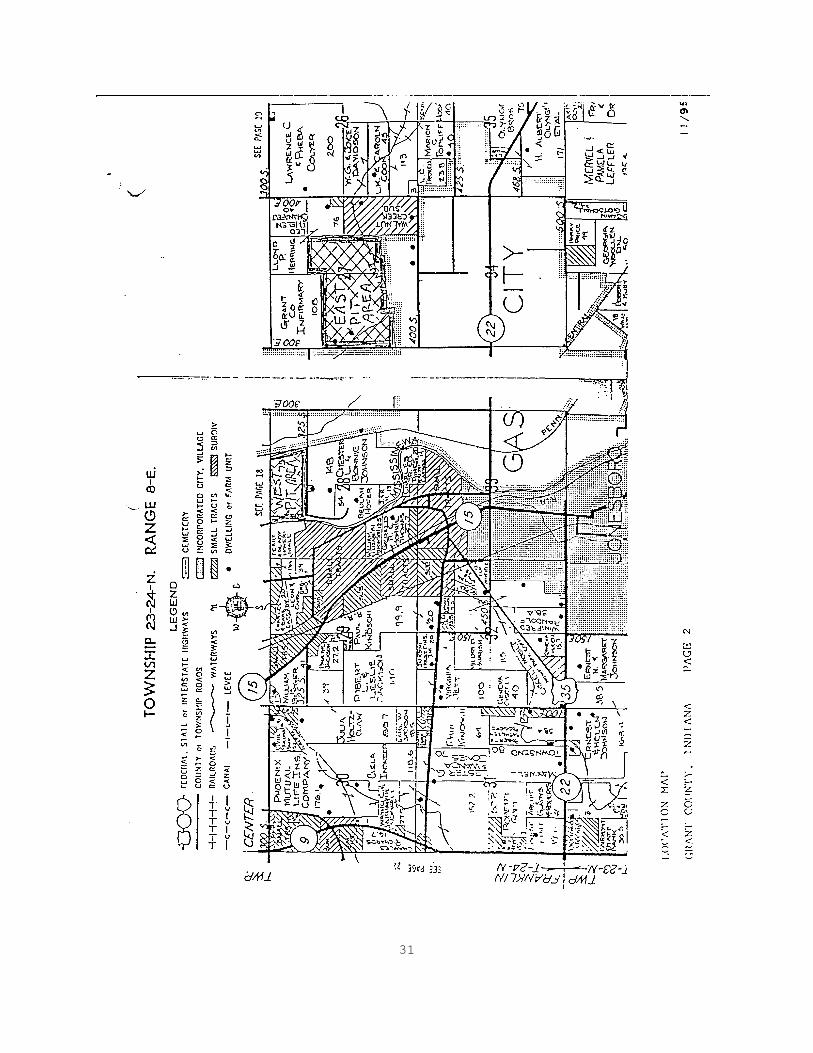
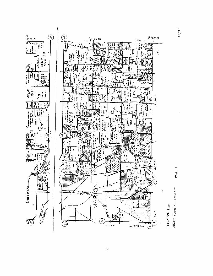
SECTION 1 PLANT LOCATION Indiana Quality Sand and Gravel, Quality Plant (2000) is classified as a Plant/Redistribution Terminal for CAPP purposes. The location of the plant is indicated on the map in Appendix B. The address and other pertinent information is as follows: Indiana Quality Sand and Gravel (INDOT #2000) 6593 Gravel Rd. Marion, IN 46713 Latitude - 40E 30, 33" Longitude - 85E 37, 05" County - Grant Township - T 24 N Range - R 8 E Sections - 21, 27 and 28 Office Phone No. - 317-675-3421 Fax - 317-675-8221 Lab - 317-992-7681 The Indiana Quality Sand and Gravel pit is situated on both sides of Gravel Road, north of Gas City. To locate the pit follow First Street north approximately 2 miles from the junction of SR 22/35. The pit entrance is on the west side of the road. Indiana Quality Sand and Gravel is owned by Gravel City, Inc. which is located at the following address: Gravel City, Inc. 618 S. 7th St. Vincennes, IN 47591 812-886-4871 FAX: 812-886-4881
4
SECTION 2 ORGANIZATIONAL STRUCTURE MANAGEMENT REPRESENTATIVES The Superintendent for Indiana Quality Sand and Gravel and Management Representative for this pit is Ron Limestone. He is responsible for all production for this site. CERTIFIED TECHNICIANS The CAPP Certified Aggregate Technician responsible for the location is Tony Shale. His duties include testing and reporting results from this site as well as assisting with the CAPP duties at several other sites within the Indiana Quality Sand and Gravel organization. Mr. Shale communicates all CAPP concerns to Mr. Limestone who then takes appropriate actions. Other Quality Control Personnel include Mary Slag and Gary Siltstone. Ms. Slag's duties include sampling and reporting test results for three sites within Indiana Quality Sand and Gravel. She may also assist at this site as the need arises. Mr. Siltstone is a CAPP Certified Aggregate Technician who will substitute for Mr. Shale when necessary.
5
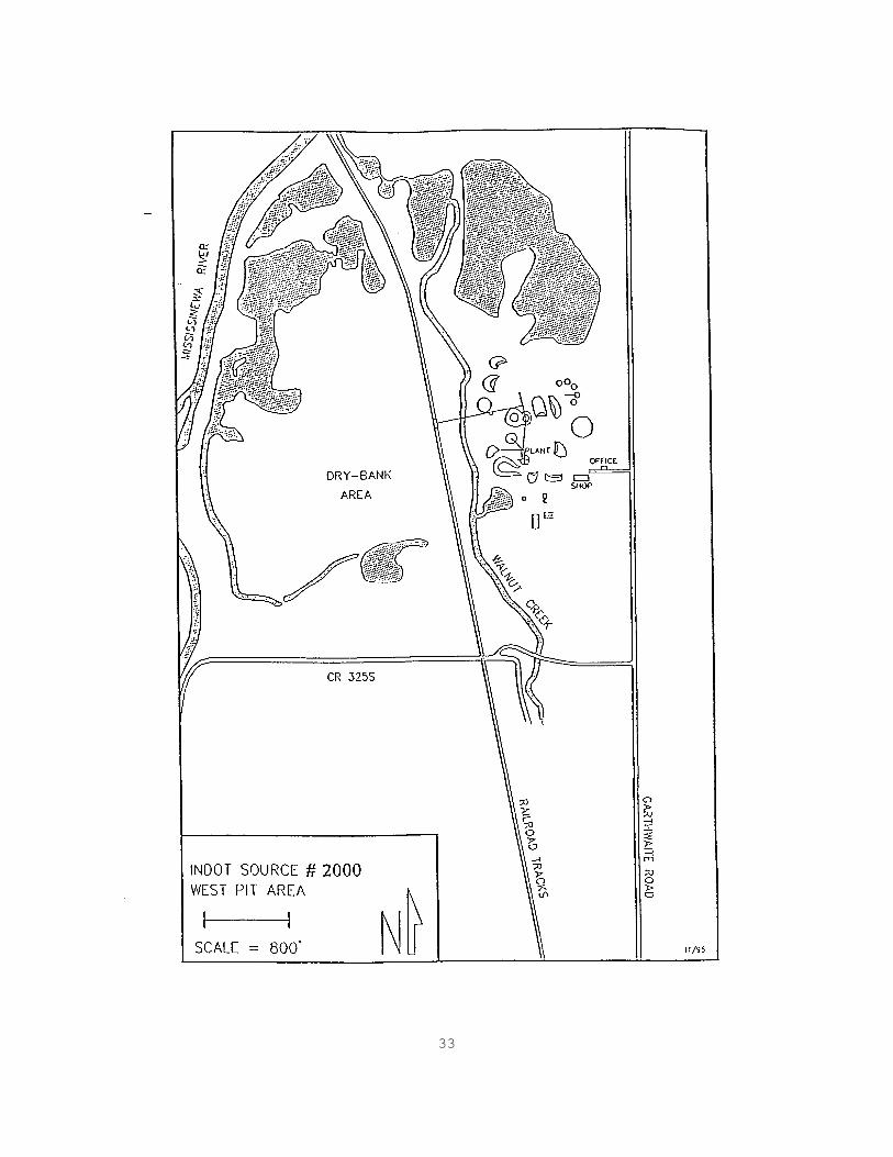
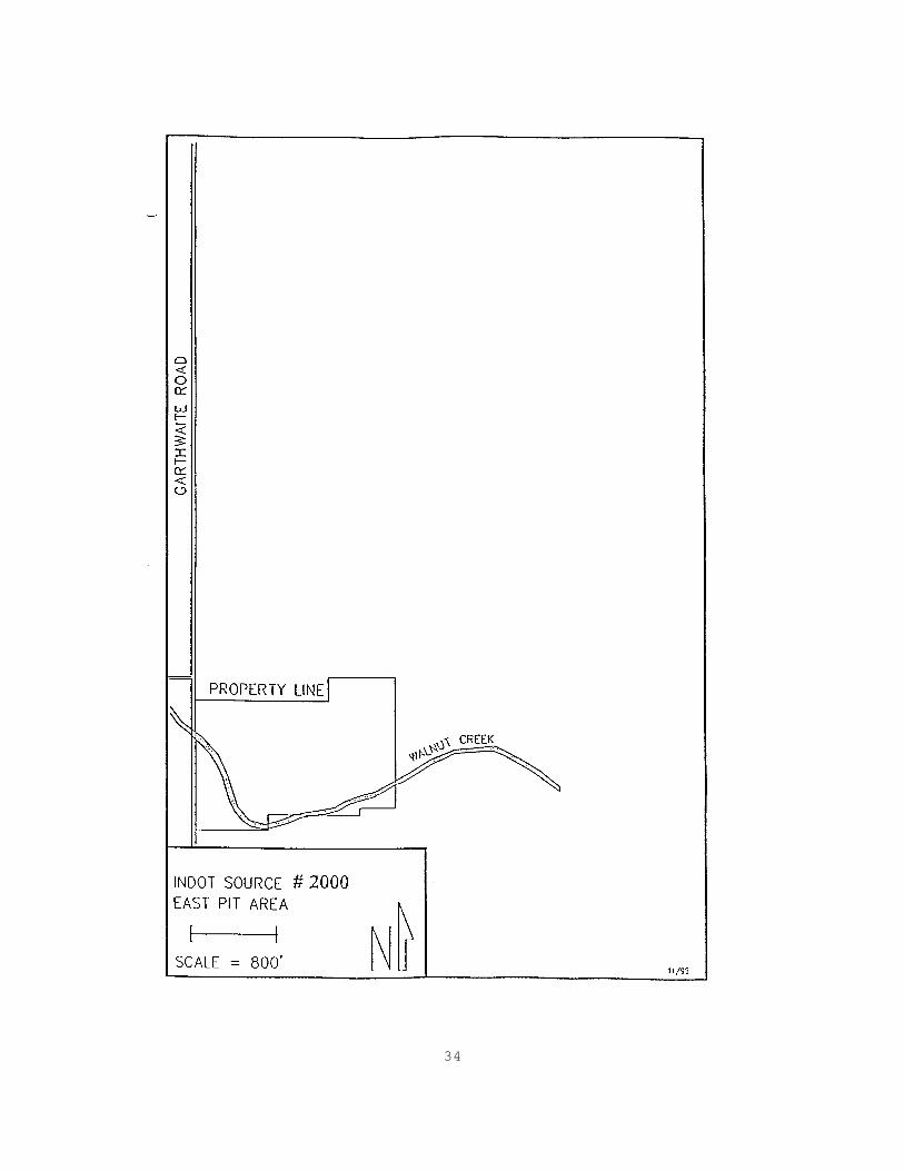
SECTION 3 MINERAL DEPOSITS The gravels and sands that are mined at this location are all derived from quaternary sediments that were reworked from earlier glacial deposits. These types of sediments are consistent with deposits that would be found on the inside curve of a large meander loop (in this case from the Mississinewa River). Since the entirety of this deposit is situated on the floor of the Mississinewa valley, this is probably correct. In addition, the proximity of Walnut Creek would lead one to suspect that it is (in part) responsible for some of the reworking and sorting of this deposit. The dry-run areas are mined to a depth of approximately 25' and the wet-run areas can be mined an additional 40'. The gravels and sands produced at this source may come from areas on the west side of Gravel Road or a newly-opened area on the east side of Gravel Road (see diagrams of pits - Appendix B). Materials originating from the west side of Gravel Road may come from any combination of different points of extraction. Materials can be selectively taken from these areas as a first measure in controlling the gradation. Depending on what products we are making, we will remove materials from any of these areas. Materials originating from the east side of Gravel Road are from one area only. This is a newly opened area and has not been developed very much at this point. This side, so far, is bank-run.

6
SECTION 4 AP AGGREGATE The gravel at this source is approved for Class AP aggregate production as indicated on the approval letter dated October 21, 1994. The AP Production Control Plan is included in Appendix A.
7
SECTION 5 MATERIAL CATEGORIES STANDARD SPECIFICATION Aggregates that are categorized as Standard Specification materials include the following INDOT sizes: #AP8 Gravel #23 Natural Sand #8 Stone This site is a Redistribution Terminal for #8 stone, which is used and stockpiled at the concrete plant on site owned by Indiana Quality Sand and Gravel. The stone comes from Stone City, Bedrock, Indiana (#2805) which is not a Certified Aggregate producer. ALTERNATE Aggregates that are categorized as Alternate materials include the following materials: #4 Gravel #12 Gravel P-Gravel Processed Pit-Run Mason Sand Construction Sand Top-Dressed Sand
8
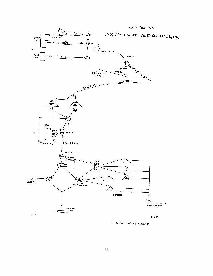
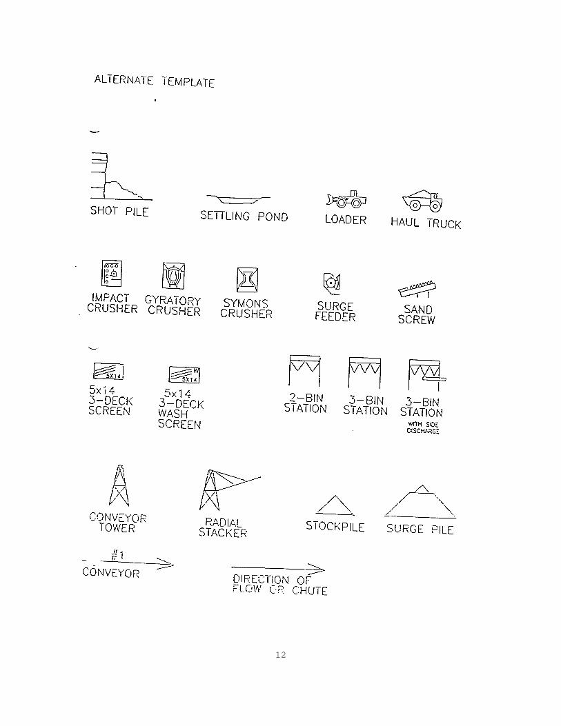
SECTION 6 PRODUCTION FLOW DIAGRAM Aggregates produced at this source are from two main areas - East Pit and West Pit. The East Pit is newly opened and presently consists of one main mining area which is dry-run. The West Pit may be mined at several points - one of which is dry-run and the others are wet-run. The East-Pit is presently restricted to dry-run materials. All materials removed from this area are placed onto haul trucks and transported to the processing plant on the west side of Gravel Road. The West-Pit is divided into dry and wet-run areas. Materials removed from the dry-run areas are loaded directly into haul trucks. Materials removed from the wet-run areas are allowed to drain before being placed onto haul trucks. Once both materials are placed onto haul trucks, they are transported to the processing plant. Materials arriving at the processing plant, from any of the mining areas, are all processed the same. The plant consists of four stations (see overall Flow Diagram on the following pages). Each station is set up to perform specific tasks within the overall process. STATION #1 This station is used only when we are making processed pit-run materials. Materials are initially placed over a Deister 5' x 10', 1-deck vibratory screening unit. Oversized materials are dropped off to the side where a loader removes them to the waste area. Materials passing through the screen are directed to the pit-run stockpile by the processed pit-run conveyor as a finished material. When not making any processed pit-run materials the aggregate is by-passed onto the east conveyor, which transports the material to either the main surge pile or the secondary surge pile by way of the surge belt. STATION #2 Station #2 is used to pre-screen and crush the materials before they are sent on to Station #3. Materials arriving at this station come from either or both surge piles by way of the 30" belt. The materials coming from the main surge pile are placed directly on the 30" conveyor while the material from the secondary surge pile is placed onto the 30" belt at a transfer point.
9
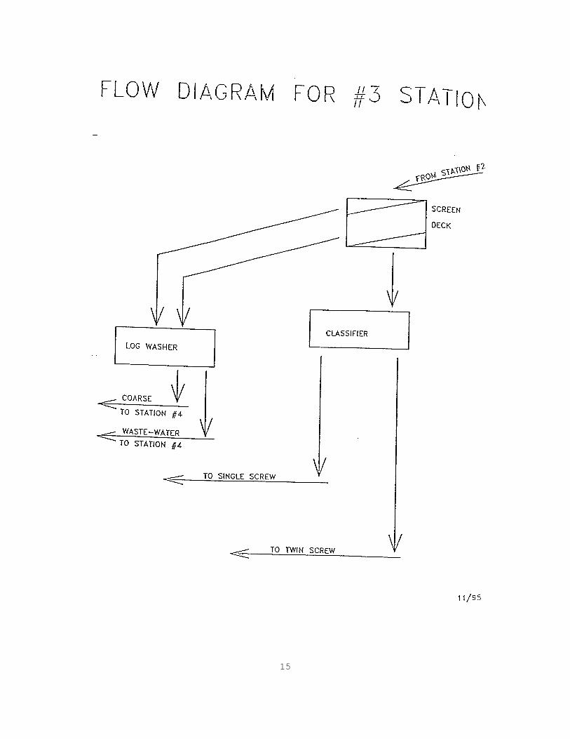
Materials at this station are put over a Deister 5' x 10', 2-deck vibratory screening unit. This screening unit sits above a single bin that merely funnels materials onto the Station #3 conveyor. Oversized materials are directed to a Lippmann 15" x 36" jaw crusher. Here they are crushed and closed-circuited back to Station #2. They first drop onto the return belt which then drops materials onto the 30" belt at a transfer point. Materials passing the top deck and retained on the bottom deck are directed to a Symons 3' standard cone crusher. Here they are crushed and closed-circuited back to Station #2. They first drop onto the return belt which then drops materials onto the 30" belt at a transfer point. Materials that pass through both screens drop into the bin and are then directed to Station #3. STATION #3 Station #3 is used to separate most of the sand from the coarser materials that are going on to Station #4. Materials arriving at this station are placed over a Deister 5' x 12', 2-deck vibratory screening unit. This station is also a wash station and includes a log washer and a classifier. Depending on what size will be produced on the bottom deck at Station #4, the sand panels on the bottom deck of this station will be set up in one of the following two ways. 1. When making #12 gravel, the panels on the bottom
deck will be configured to produce mason/construction sand. 2. When making P-gravel, the panels on the bottom deck
will be configured to produce #23 sand. All materials that do not pass through the bottom deck are directed to the Eagle Iron Works log washer. At the log washer, materials are pre-washed in preparation for their arrival at Station #4. Waste-water exits the log washer and is directed to the twin screw at Station #4. All materials that pass through the bottom deck are directed to the Eagle Iron Works classifier. At the classifier, fine materials are sent to the McClanahan 36" single sand screw and come off as top-dress sand. At the classifier, coarse materials are sent to the Eagle Iron Works 36" twin sand screw and come off as either #23 or mason/construction sand. This is the same screw to which materials from Station #4 will be directed. From either screw, the waste water is directed to the settling ponds.

10
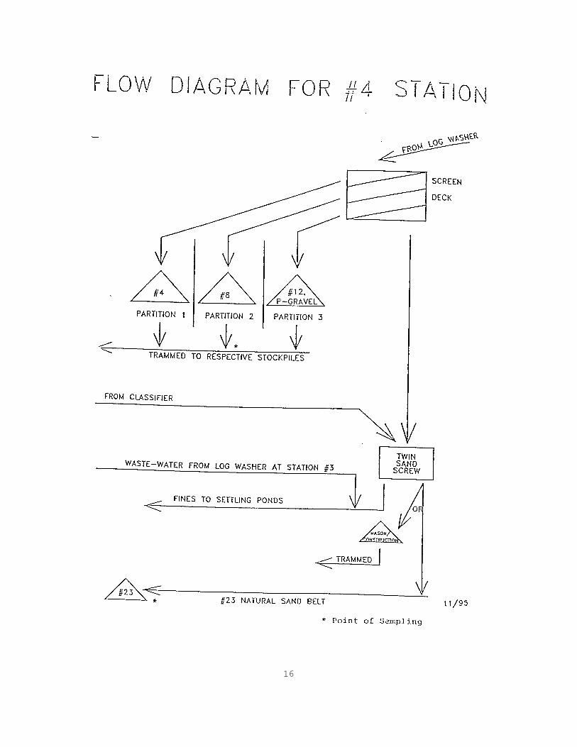
STATION #4 Washed products are made at Station #4. Materials arriving at this station are put over a Deister 5" x 10', 3-deck vibrating screening unit. Since this material has been pre-screened, each bin partition will contain the following finished products: 1. Top-sized materials are size #4 and drop into the first
bin partition. They are scooped up with the front-end loader and trammed to the stockpile.
2. Materials passing the top deck and retained on the
middle deck are size #8 and drop into the middle bin partition.
3. Materials passing the middle deck and retained on the
bottom deck are #12 size or P-gravel and drop into the third bin partition. When set up to make mason/construction sand at Station #3, this station will make #12 gravel. When set up to make #23 sand at Station #3, this station will make P-gravel.
4. Material passing through all of the screens is sent to
the sand screw. At the sand screw, one of three types of sand may be produced. When making #23 sand, the sand coming off the screw drops onto a conveyor belt and is taken directly to the #23 sand stockpile. When making mason sand or construction sand, the sand coming off the screw is diverted from the #23 conveyor and is dropped off onto the mason sand belt and sent to the tram pile to await stockpiling. Waste water from the sand screws is sent to the settling ponds.
11
12

13

14
15
16
17
SECTION 7 SAMPLING PLAN Indiana Quality Sand and Gravel has developed a coding scheme to distinguish the 5 different types of samples that are obtained. The type of samples, frequency of sampling, location of samples and sampling procedures of any Certified Materials are included as follows. TYPE OF SAMPLES AND FREQUENCY (S) Start of Production. After a seasonal shutdown or when producing a new material, start of production samples shall be obtained once every 1000 t for the first 5000 t, but shall not exceed 2 per calendar day. (N) Normal Production. After the start of production samples have been completed for each material, normal production samples shall be obtained. The frequency of these samples shall be once every 2000 t, but shall not exceed 2 per calendar day. (L) Load-Out. Load-out samples shall be taken from material that is shipped. The frequency of these samples shall be once every 8000 t; however, there shall be at least one sample taken each month for any Certified Material shipped that exceeds 1000 t. (M) Miscellaneous. Miscellaneous samples are taken at our own discretion for information purposes outside the start of production or normal production samples. (R) Resample. When there is a failing normal production or load-out test a resample shall be taken. MEANS OF TRACKING SAMPLES Start of production and normal production samples shall be taken from uniform tonnage increments in an unbiased manner. The belt feed rates shall be used to estimate the quantity produced. The Superintendent shall be responsible for communicating with production staff as to when to obtain samples. Shipping tonnages shall be kept by the office bookkeepers to determine when the load-out samples are to be obtained. The bookkeepers shall inform the Superintendent when a sample is required.
18
SAMPLE LOCATIONS All start of production and normal production samples shall be taken from the following locations. 1. #8 GRAVEL - stockpiles made by a front-end loader with
material from the bin partitions. 2. #8 STONE - the active area of the finished stockpile. 3. #23 SAND - the active area of the finished stockpile. Load-out samples shall be taken from the Certified Material stockpiles. The points of sampling for all samples are indicated on the flow diagram on page 6-4. SAMPLING PROCEDURES The #8 stone and #23 sand samples shall be obtained using the procedure for stockpile sampling as set out in the ITM 207. Samples of the #8 gravel from the bin partition shall be obtained by first emptying the bin and then passing a container through the discharge stream.

19
SECTION 8 TESTING PLAN GRADATION Gradation analysis shall be performed in accordance with AASHTO T 27 on all start of production, normal production and load-out samples. A gradation test shall be performed on resample and miscellaneous samples when necessary. DECANT Decant tests shall be performed in accordance with AASHTO T 11 on all load-out samples. CRUSHED PARTICLES Crushed particle content for the #8 gravel shall be determined in accordance with ASTM D 5821 at least once per week for the start of production and normal production samples. No test shall be performed if the week's production is less than 100 t. DELETERIOUS The percent of deleterious materials shall be determined in accordance with AASHTO T 112, ITM 206, and the Standard Specifications at least once per week for each size of material for the start of production and normal production samples. No test shall be performed if the week's production is less than 100 Mg. Previous testing has indicated that there are high levels of light-weight chert at this source. For this reason, when the total chert exceeds the specification limit for light-weight chert the District Materials and Tests Engineer shall be notified and samples shall be obtained for INDOT to test for light-weight chert. NON-CONFORMING MATERIAL Any time there is a failing normal production or load-out test the Superintendent shall be notified immediately and a resample test taken. Typically, retests shall be accompanied by a visual check for any problems at the plant. All actions shall be documented in the Daily Diary. In the event that a second consecutive normal production sample fails, the materials will be diverted until the problem is corrected as follows:
20
1. No. 8 gravel and No. 8 stone shall be taken to the scrap pile and wasted.
2. No. 23 sand shall be diverted to the mason/construction
sand conveyor. In the event that a second consecutive load-out sample fails, shipping from that stockpile shall cease. The stockpile problem area shall be checked to determine if the stockpile can be remixed and restored within the quality control limits as verified by the resample tests. If the problem area cannot be remixed, the material shall be removed and taken to the scrap pile.
21
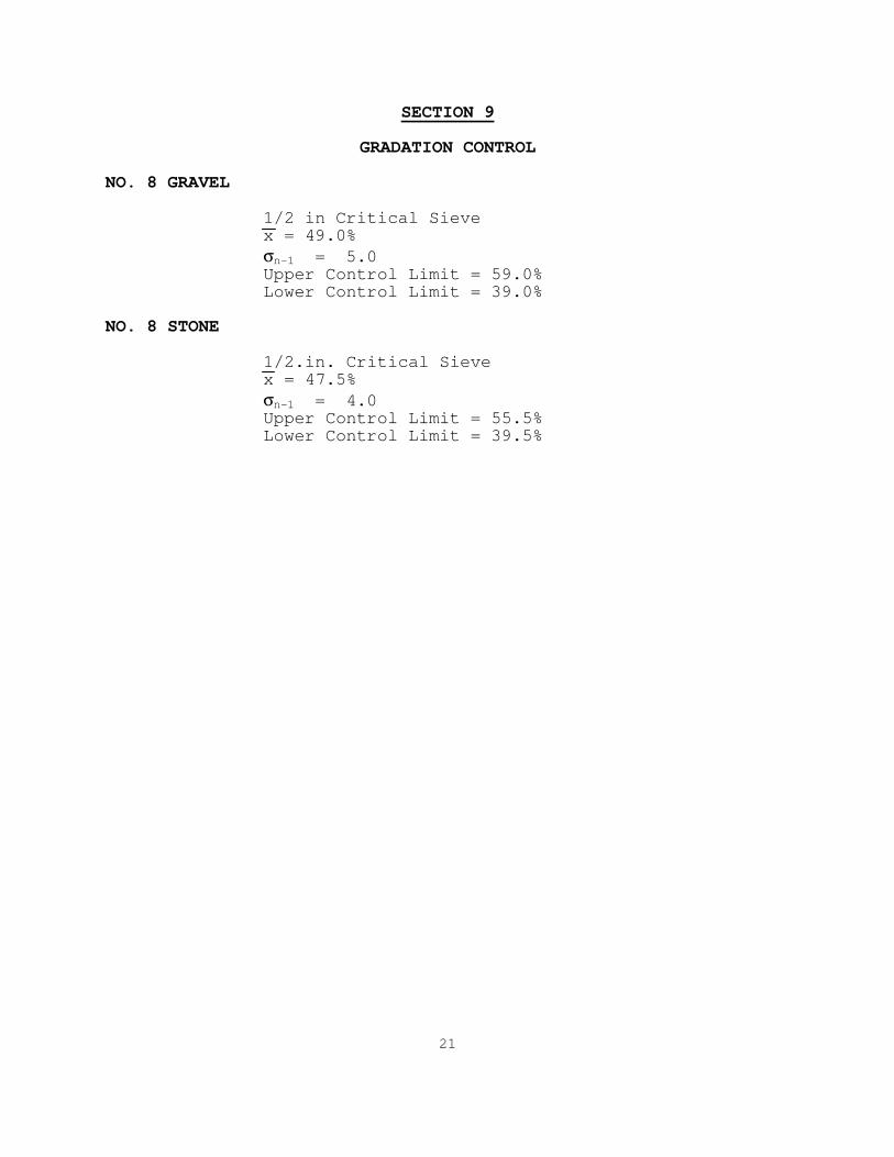
SECTION 9 GRADATION CONTROL NO. 8 GRAVEL 1/2 in Critical Sieve x = 49.0%
σn-1 = 5.0 Upper Control Limit = 59.0% Lower Control Limit = 39.0% NO. 8 STONE 1/2.in. Critical Sieve x = 47.5%
σn-1 = 4.0 Upper Control Limit = 55.5% Lower Control Limit = 39.5%
22
SECTION 10 PROCESS CONTROL TECHNIQUES Los Angeles abrasion and absorption tests may be performed when deemed necessary and shall be posted on the Gradation Analysis Form (Appendix C). A visual check of all stockpiles is an ongoing daily procedure.
23
SECTION 11 DOWNSTREAM CONTROL IDENTIFICATION OF STOCKPILES All stockpiles shall be marked using signs in front of each stockpile that indicate the size of each material. For Standard Specification stockpiles, the signs shall be blue with white lettering and for Alternate stockpiles, the signs shall be red with white lettering. STOCKPILE CONSTRUCTION The #8 gravel stockpile is constructed by tramming materials with a front-end loader from the bin partitions. The #8 stone stockpile is constructed by unloading truck loads side by side and then stacking the material only as high as the front-end loader can place the material. The #23 sand is deposited directly onto the stockpile from the #23 sand belt. MATERIAL RETRIEVAL The entire front face of each stockpile shall be worked by a front-end loader from side to side when loading the truck. The sides of the face shall be occasionally mixed with the center to prevent segregation of the stockpile.
24
SECTION 12 LABORATORY LOCATION The laboratory is located in the southwest corner of the shop building, which is situated east of the plant. The following verified equipment is maintained in the laboratory: EQUIPMENT Sieve Analysis Gilson TS-1 shaker 15 in. x 23 in. screens (2 in. (50 mm), 1½ in. (37.5
mm), 1 in. (25 mm), 3/4 in. (19.0 mm), 1/2 in. (12.5 mm), 3/8 in (9.5 mm), No. 4 (4.75 mm) and pan)
Gilson Ro-Tap shaker 8 in. round sieves (3/8 in. (9.5 mm), No. 4 (4.75 mm),
No. 8 (2.36 mm), No. 16 (1.18 mm), No. 30 (600 µm), No. 50 (300 µm), No. 100 (150 µm), No. 200 (75 µm) and pan)
General Humboldt oven Ohaus IP12KS Digital Electronic Balance (12000 g capacity) Mettler H10 Electronic Balance (160 g capacity) CALIBRATION
The balances, mechanical shakers, oven, and sieves shall be verified in accordance with the following: Minimum Equipment Frequency Procedure Balances 12 mo. ITM 910 Mechanical Shakers 12 mo. ITM 906 Sieves 12 mo. ITM 902

25
SECTION 13 DOCUMENTATION PLAN Several forms have been developed for the CAP program and all information regarding the CAPP shall be entered on these forms. Examples of these forms may be found in Appendix C. REFERENCE DOCUMENTS The following documents are on file at the lab: 1. INDOT Certified Aggregate Producer Program (ITM 211) 2. INDOT Standard Specifications and Current Supplemental
Specifications 3. INDOT Inspection and Sampling Procedures for Fine and
Coarse Aggregate 4. Indiana Quality Assurance Certified Aggregate
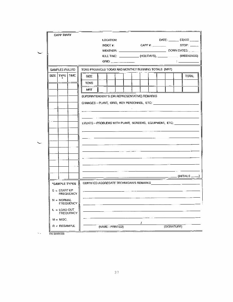
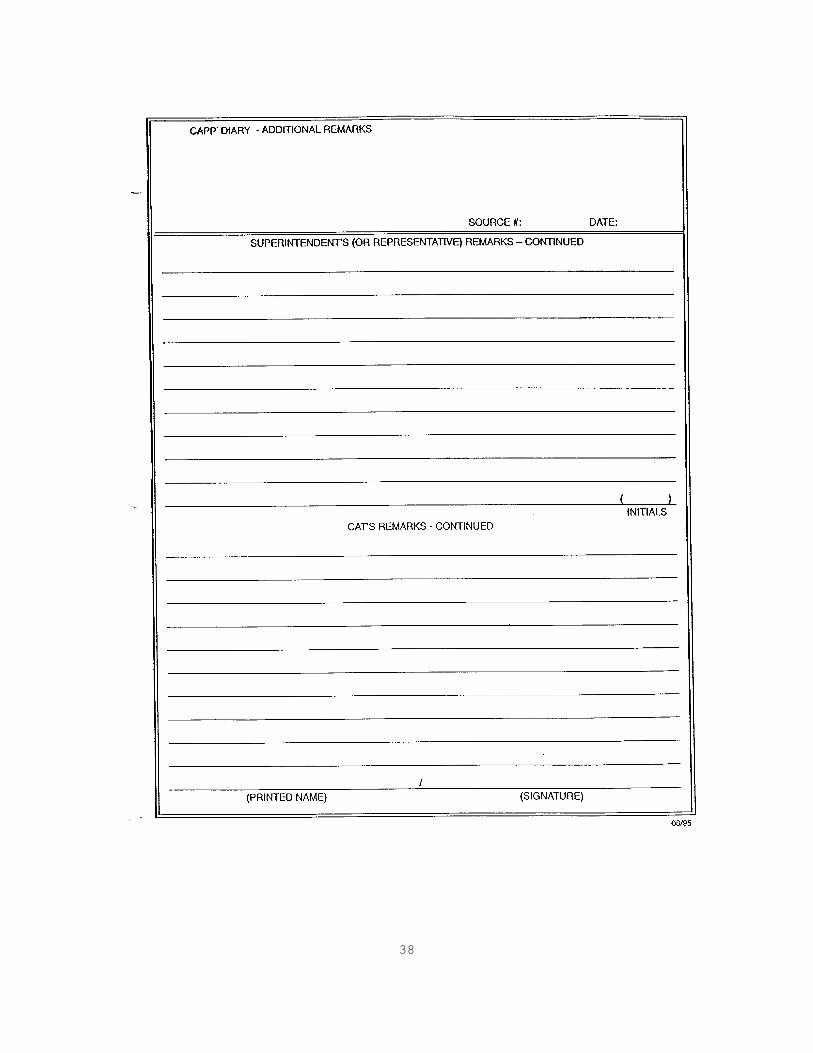
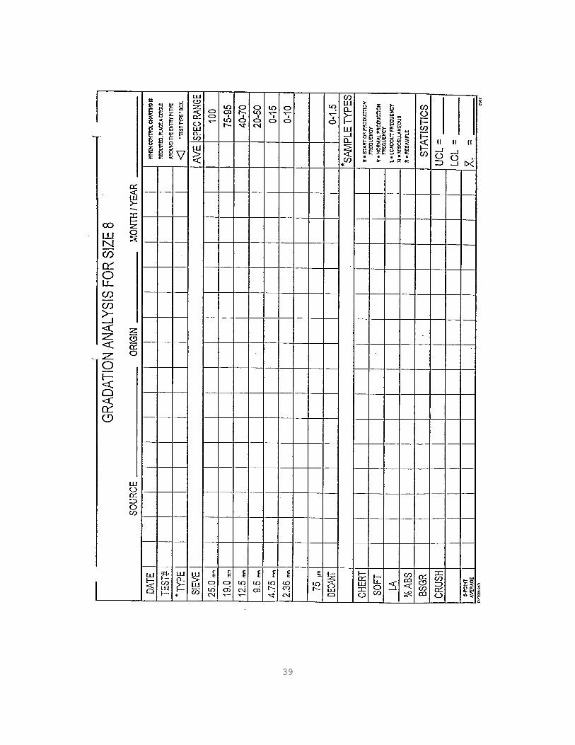
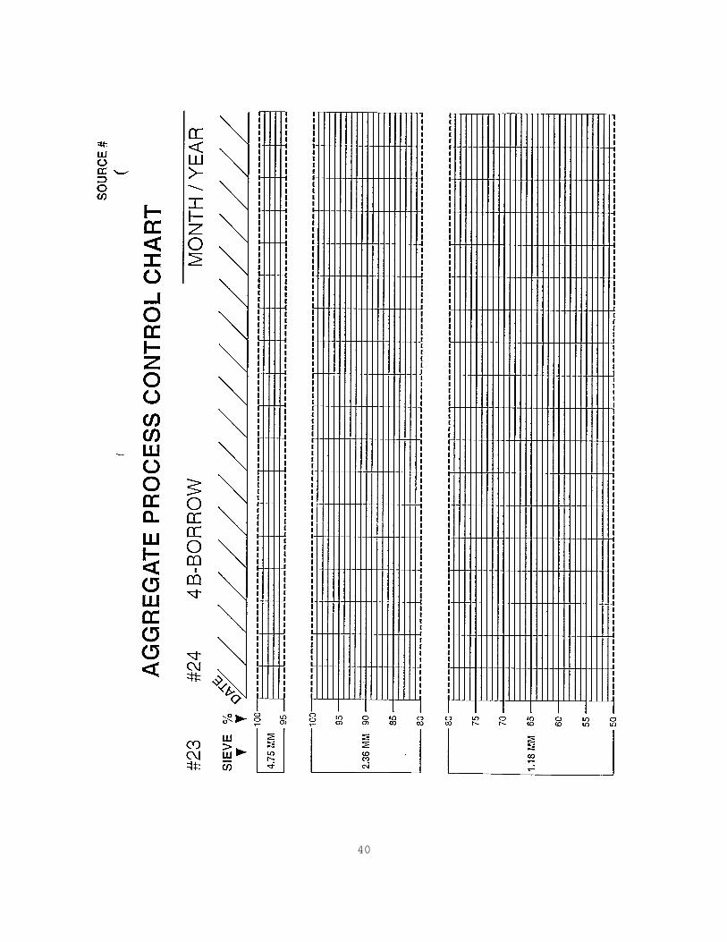
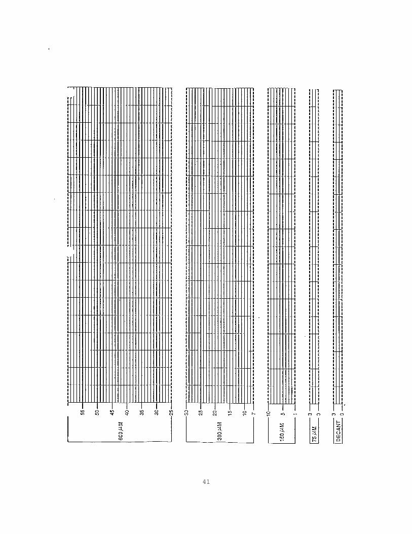
Technician Training Manual for Producer Technicians 5. Summary of Production Quality Results 6. AP Aggregate Letter 7. Quality Control Plan DIARY The diary is located in the Superintendent's office. One page is devoted to each day of the year that there is a material related operation, and all pages are maintained in a 3-ring binder. AGGREGATE INSPECTOR RECORD BOOK Each aggregate inspector working for this company is issued a number which is unique to that individual. Test data is recorded in the Aggregate Inspector Record Book and is traceable to any inspector through the identification number. This document is located in the laboratory. GRADATION ANALYSIS FORM This form is used for a quick visual comparison of up to 16 separate gradations of like materials. There is a different version of this form for each size of CAPP material including a generic version that may be used for any other material. This document is located in the laboratory. CONTROL CHARTS Control charts for each size material are posted on the wall in the laboratory.

26
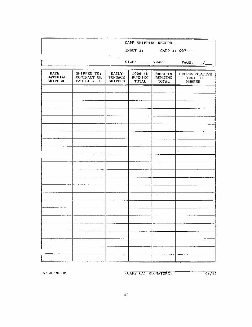
INDOT MATERIAL SHIPPING RECORD FORM This form was developed to assist our bookkeepers in keeping track of how many tons of each material are shipped from the Certified Material stockpiles. This form is readily available to INDOT personnel at the office.
27
SECTION 14 ADDENDA Each page in the Quality Control Plan that is revised shall have the source number, date of revision, and a vertical line in the left margin indicating the paragraph that was revised. Revisions to the QCP shall be maintained on an Addenda Summary Sheet or QCP Annex in the Appendix until such time that the revisions are incorporated into the QCP. Addenda shall be submitted at the close-out meeting for an annual audit. Any outstanding revisions will also be submitted in January of each year.
28
APPENDIX A AP PRODUCTION CONTROL PLAN

29
AP PRODUCTION CONTROL PLAN INDIANA QUALITY SAND & GRAVEL, INC. INDOT SOURCE #2000 Indiana Quality Sand and Gravel, Inc. is approved for Class AP aggregate, and produces and controls gravel meeting this classification in accordance with the following: 1. The production area for the AP gravel is the west side
of Gravel Road. A diagram of the pit is included in Appendix B.
2. AP gravel will be processed in accordance with the
procedures listed in Section 6. 3. The final production gradation for the AP gravel will
be INDOT size #8 gradation. 4. The AP stockpile will be identified by a sign
indicating AP No. 8, and the location and color of the sign will be in accordance with Section 11.
5. AP gravel delivered to concrete plants will be so
identified on the aggregate weigh tickets.
30
APPENDIX B GENERAL INFORMATION
31
32
33
34

35

36
APPENDIX C FORMS
37
38
39
40
41
42
43
AUTHENTICATION APPROVAL SUBMISSION _________________________________ ________________________ Chief, Materials & Tests Division Management Representative ________________ __________________ Date of Approval Date of Submission


