DocuTech 61xx Production Publisher Family 701P48388 February 19, 2008 Operator HandyBook The purpose of this HandyBook is to provide a quick reference for the operator. It does not replace the Operator Guide or other Xerox supplied reference materials. More information is available at www.Xerox.com . The Operator Guide is available for download as well.
Transcript
DocuTech 61xx Production Publisher Family 701P48388 February 19, 2008
Operator HandyBook The purpose of this HandyBook is to provide a quick reference for the operator. It does not replace the Operator Guide or other Xerox supplied reference materials. More information is available at www.Xerox.com. The Operator Guide is available for download as well.
Table of Contents Table of Contents...................................................................... 3 1. System Hardware ................................................................. 7
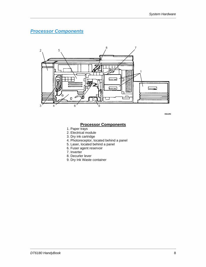
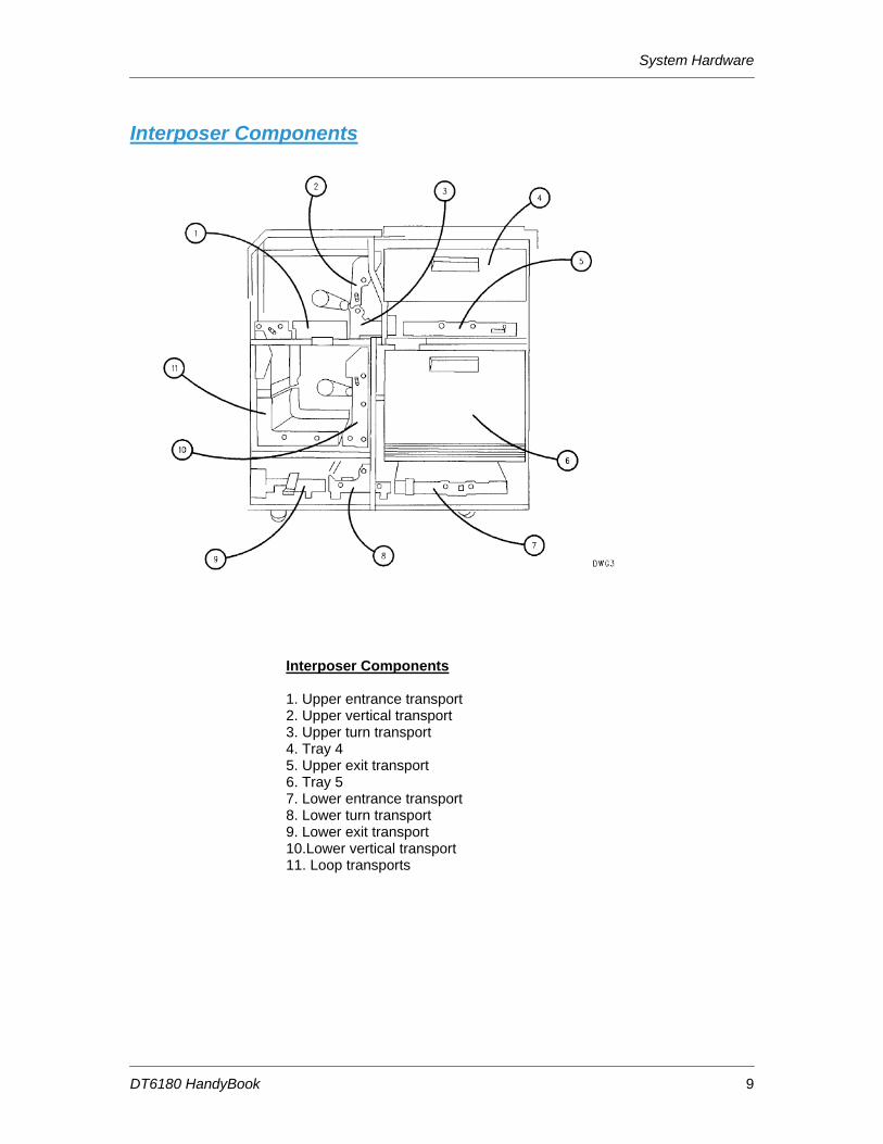
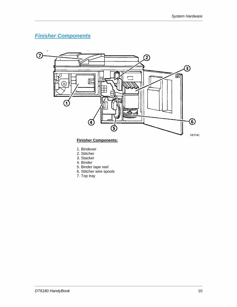
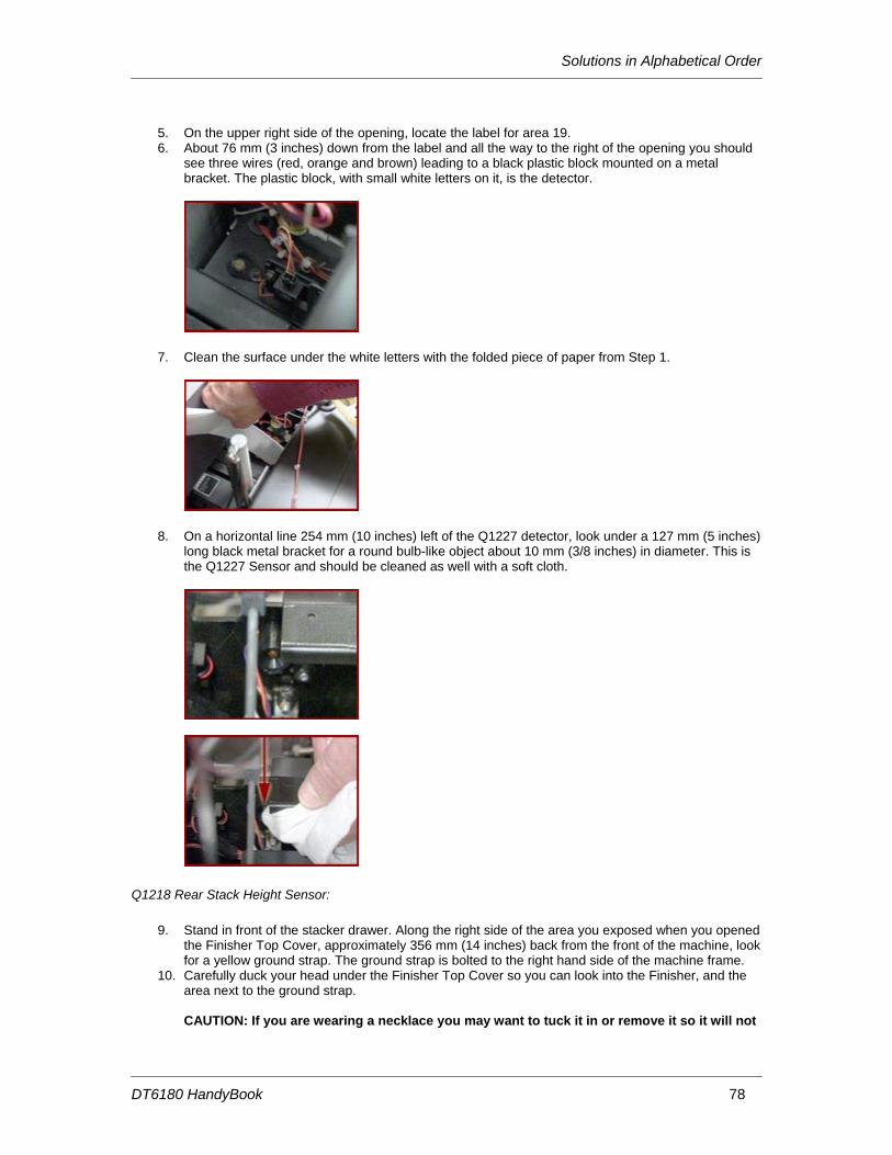
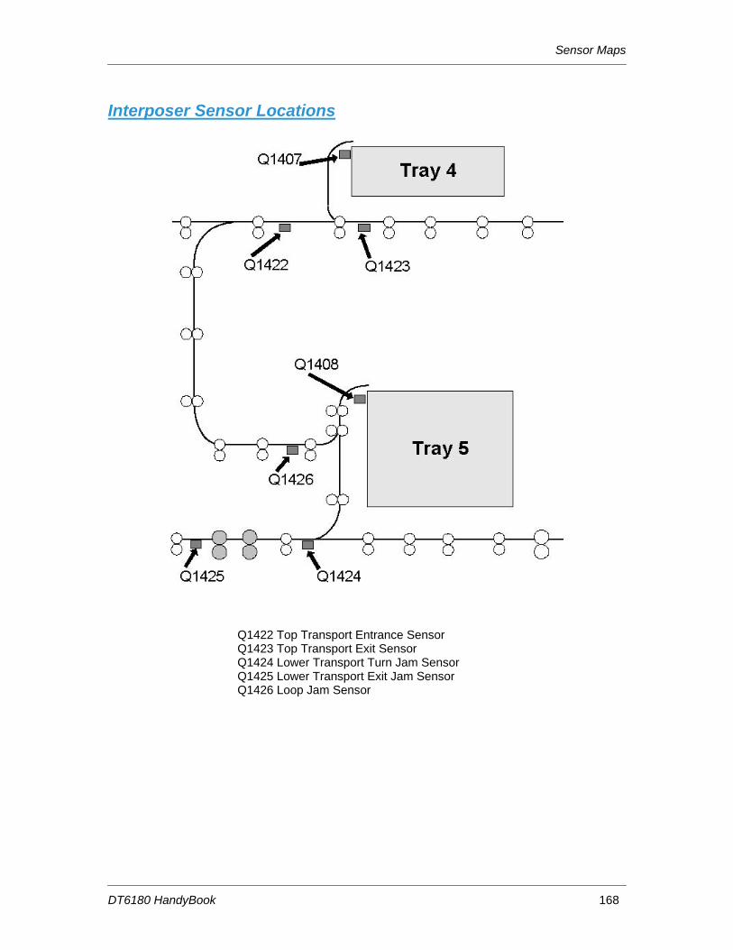
Processor Components ................................................................................................................ 8 Interposer Components ................................................................................................................ 9 Finisher Components ................................................................................................................. 10 Paper Path Areas ....................................................................................................................... 11
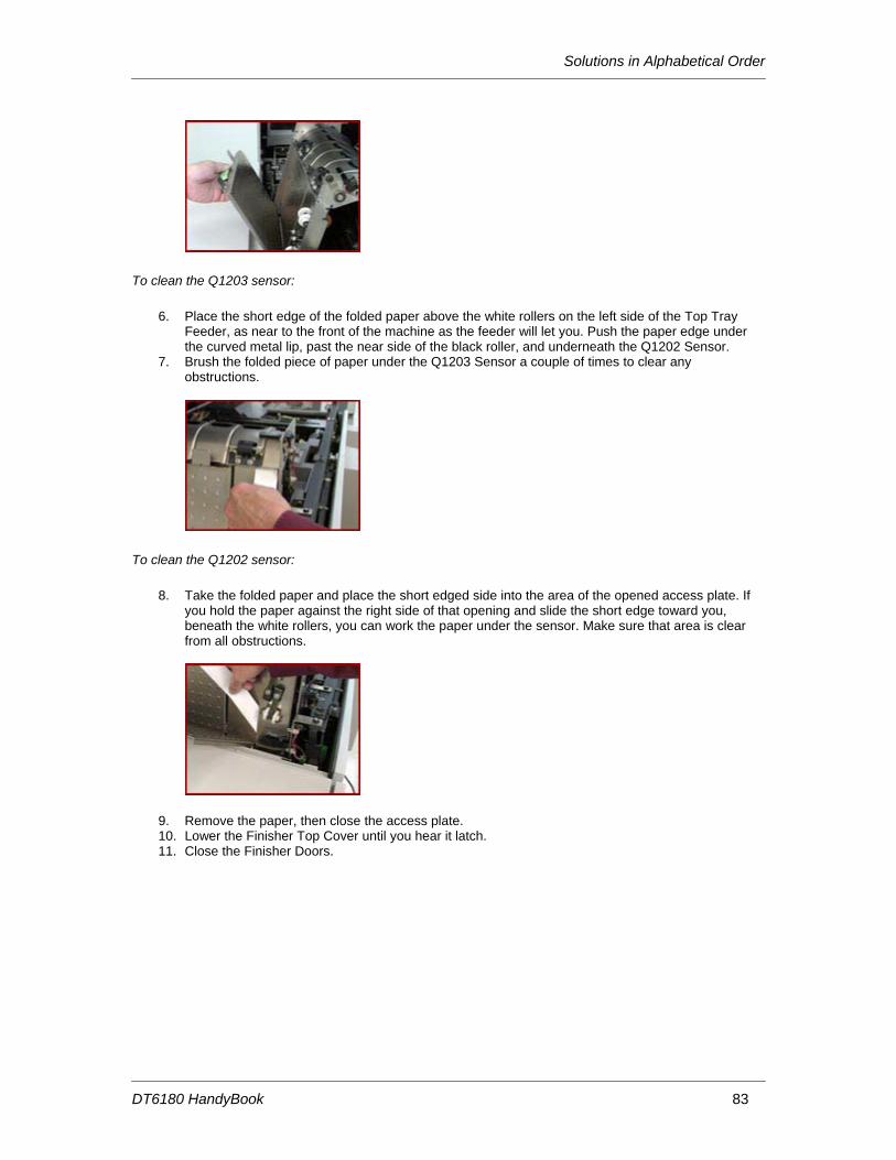
2. Paper Trays & Loading Media........................................... 13 Paper Tray & Finisher Capacities............................................................................................... 13 Adding Paper to Tray 1 or 2 ....................................................................................................... 16 Adding Paper to Trays 3, 4, or 5................................................................................................. 18 Loading Transparencies ............................................................................................................. 19 Re-Loading Tabs ........................................................................................................................ 19 Adding Inserts............................................................................................................................. 20 Satisfaction Guides..................................................................................................................... 21
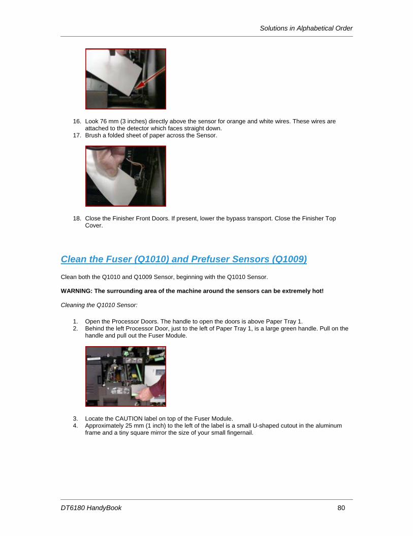
Satisfaction Guide for Paper Trays 1 and 2 .................................................................. 21 Satisfaction Guide for Paper Tray 3 .............................................................................. 22 Satisfaction Guide for Paper Tray 4 .............................................................................. 23 Satisfaction Guide for Paper Tray 5 .............................................................................. 23 Satisfaction Guide for 2-Sided Printing ......................................................................... 24 Satisfaction Guide for Various Stocks ........................................................................... 24 Satisfaction Guide for Stitcher....................................................................................... 26
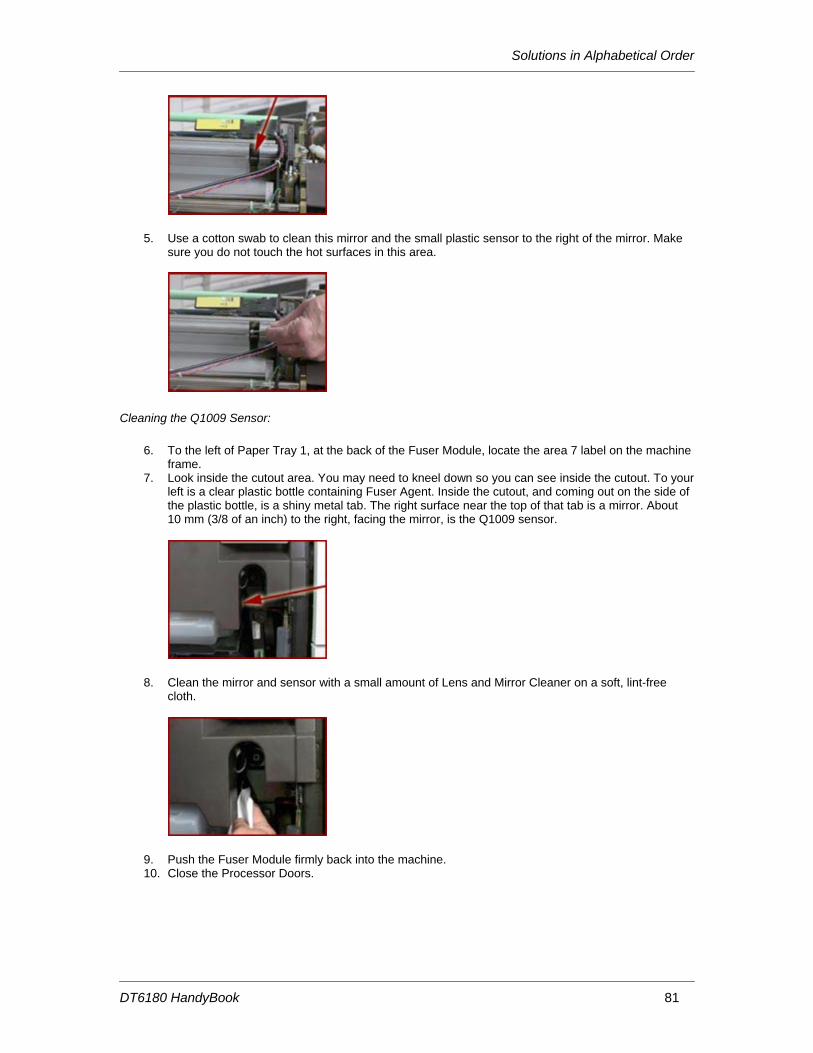
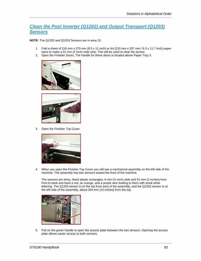
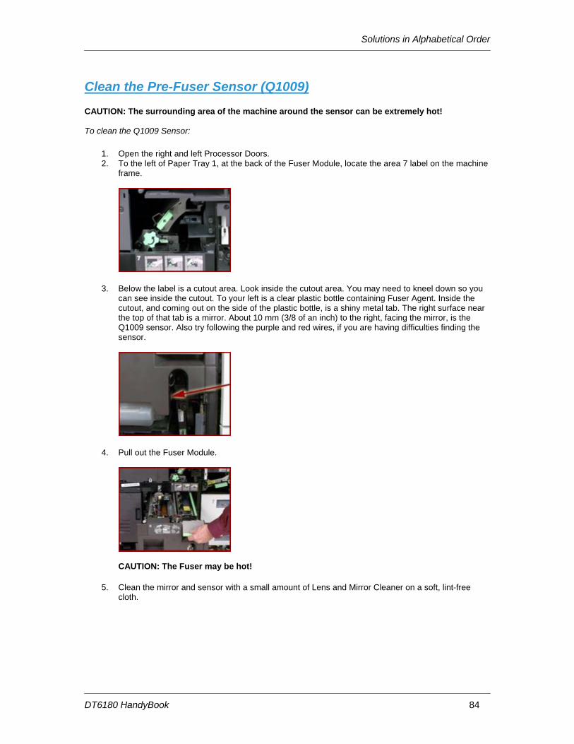
Add Fuser Agent........................................................................................................................ 29 Replace Stitcher A Wire ............................................................................................................. 31 Replace the Binder Tape Reel ................................................................................................... 34 Replace the Toner (Dry Ink) Bottle............................................................................................. 37 Replace the Toner (Dry Ink) Waste Container ........................................................................... 38 Order Supplies, Consumables, and Parts .................................................................................. 40
5. Machine Maintenance ........................................................ 41 Adjusting for Paper Curl ............................................................................................................. 41 Adjusting the Heavy Paper Levers ............................................................................................. 44 Adjust the Binder Tape Registration........................................................................................... 46 Enable a Paper Tray for Clean up.............................................................................................. 47 Enable or Disable the Binder...................................................................................................... 47 Enable or Disable the Stacker .................................................................................................... 48 Enable or Disable the Stitcher .................................................................................................... 48 Modify the Bindexer Capacity Number....................................................................................... 49 Modify the Lighter / Darker Setting............................................................................................. 49 Stop a Job From Printing at the Printer ...................................................................................... 50
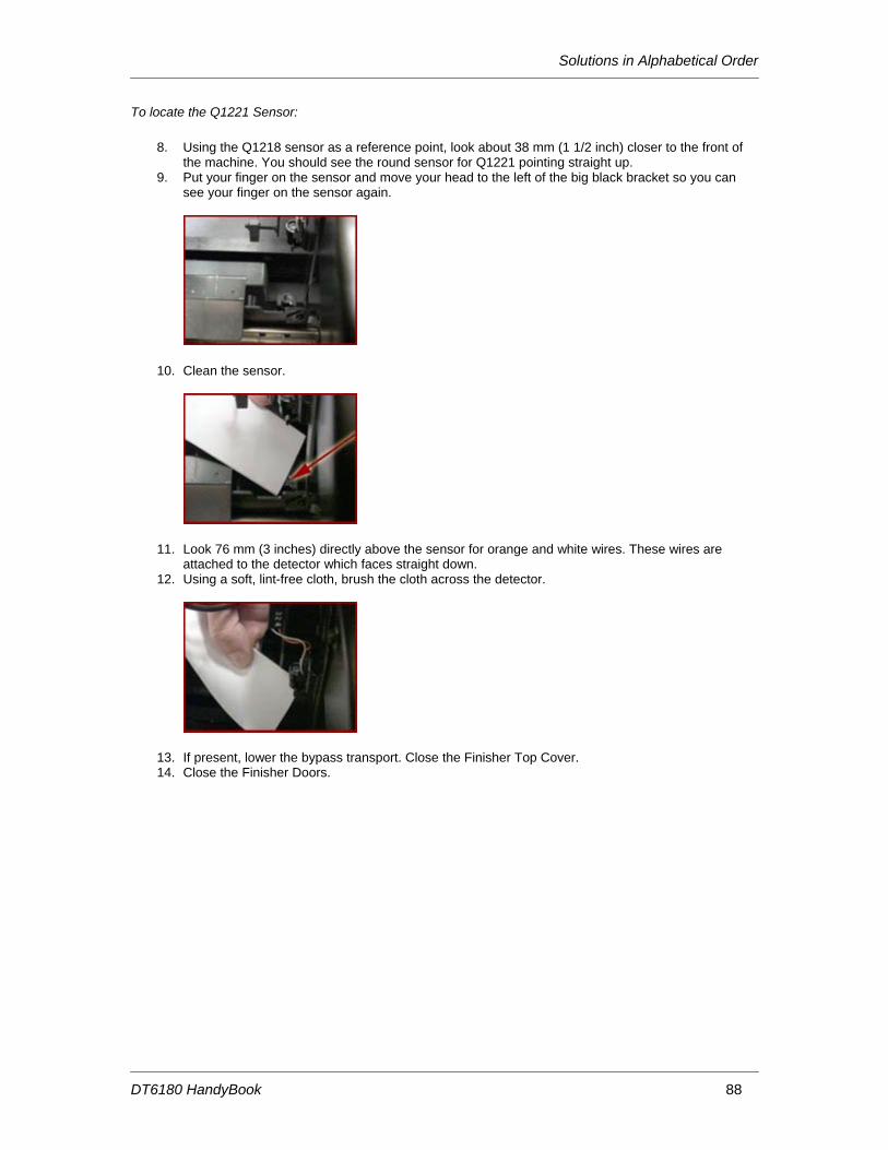
6. Problem Solving................................................................. 51 COMMON FAULT CODES & CASE .......................................................................................... 52 PROBLEM LISTING AND SOLUTIONS, LISTED by CASE NUMBER ..................................... 55 Solutions in Alphabetical Order .................................................................................................. 66 Clean Finisher Entrance Sensor (Q1201) .................................................................................. 68 Clean the Bin A Bindexer Sensor (Q1205)................................................................................. 71 Clean the Bin B Bindexer Sensor (Q1206)................................................................................. 72 Clean the Binder Tape Guide Sensor (Q1213) .......................................................................... 73
DT6180 HandyBook
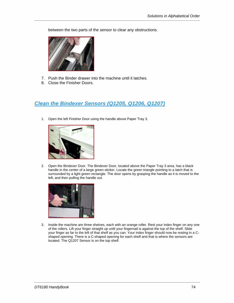
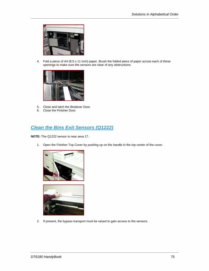
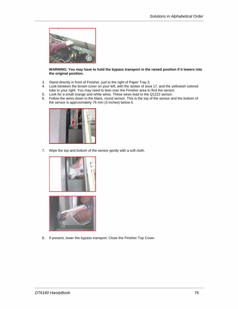
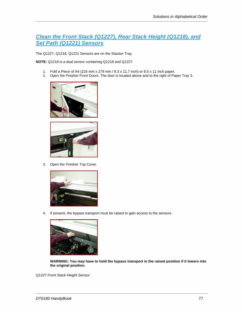
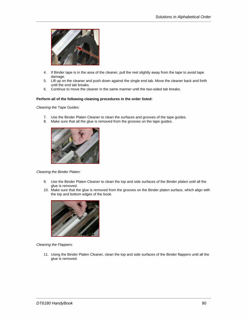
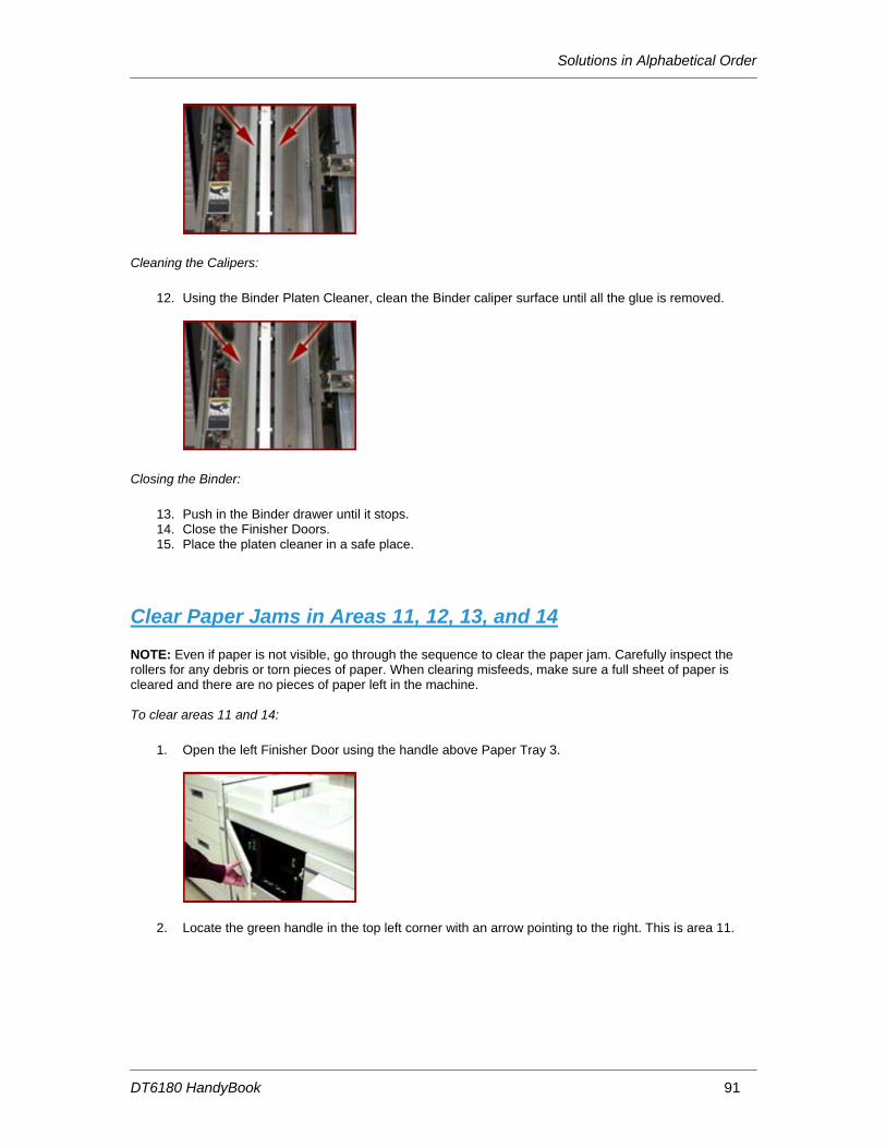
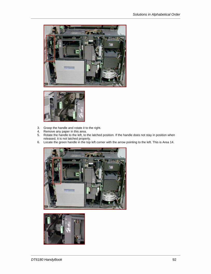
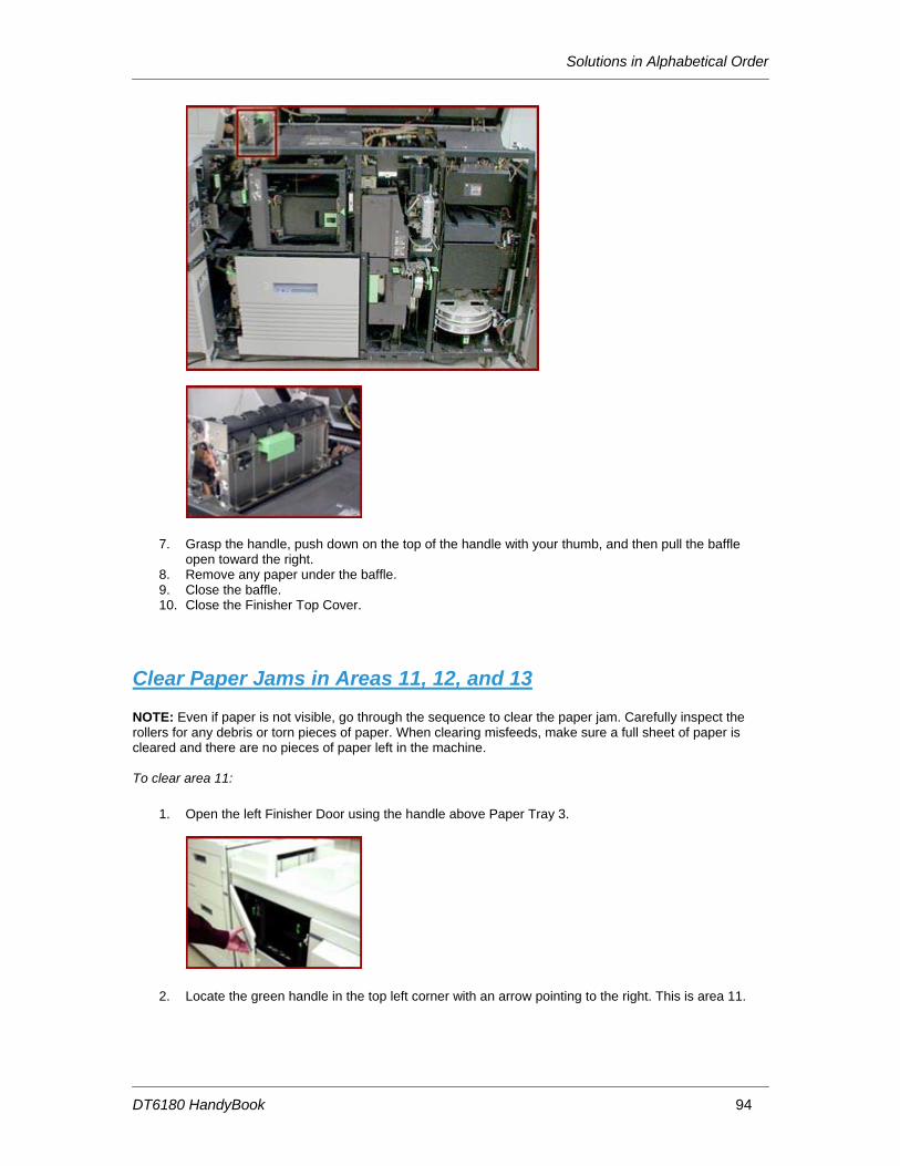
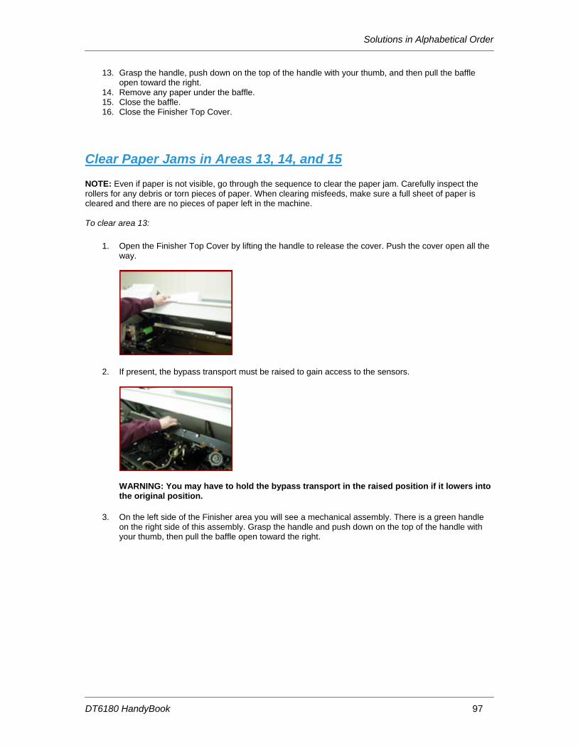
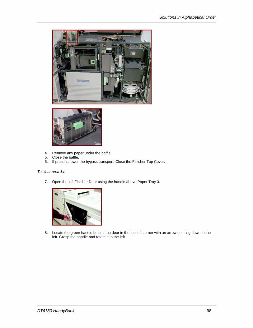
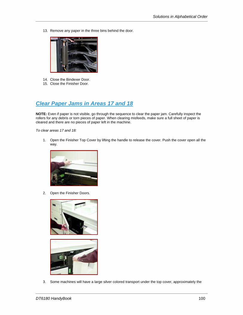
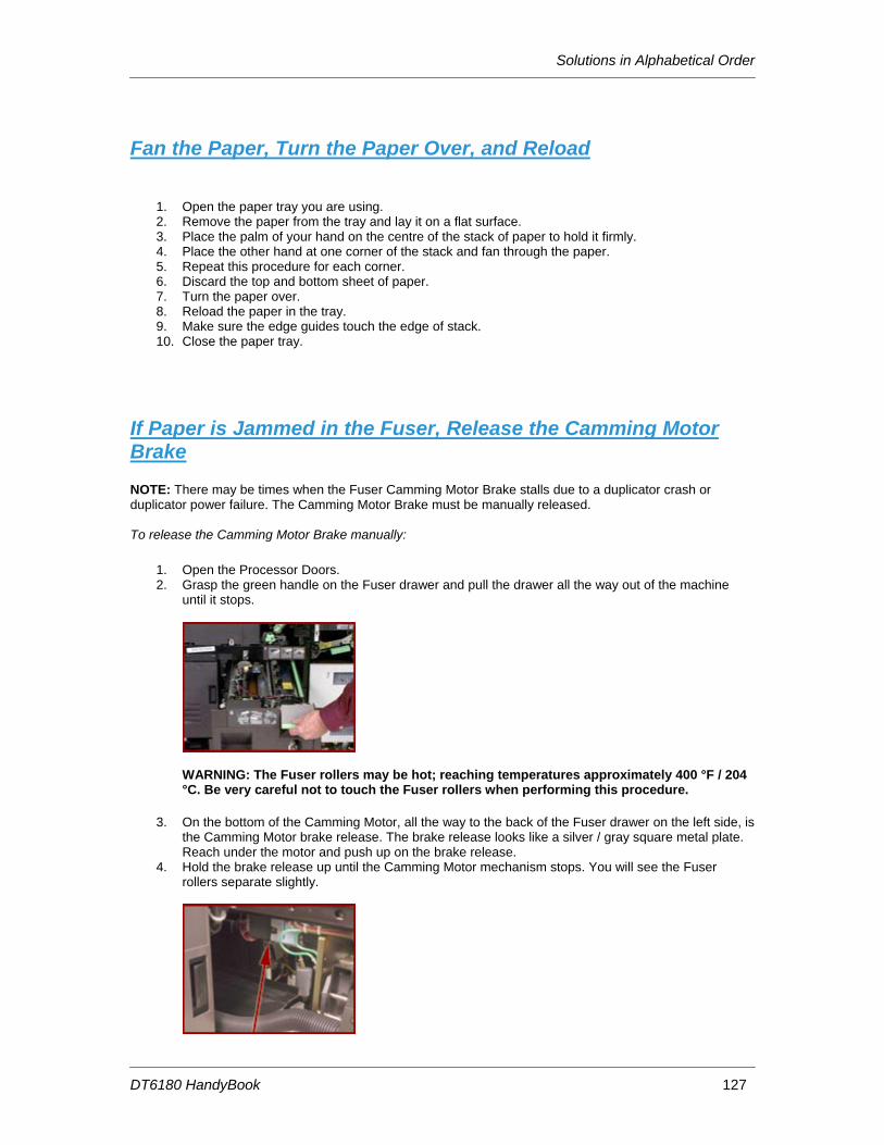
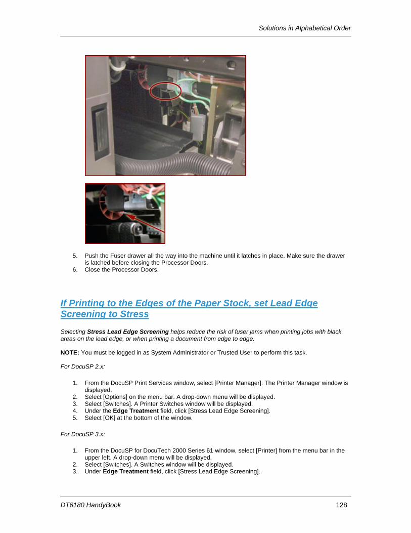
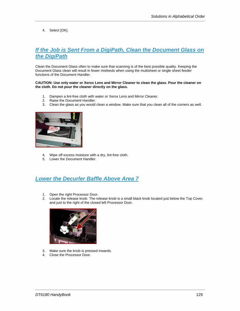
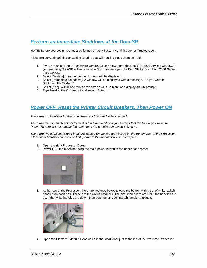
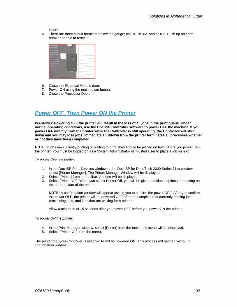
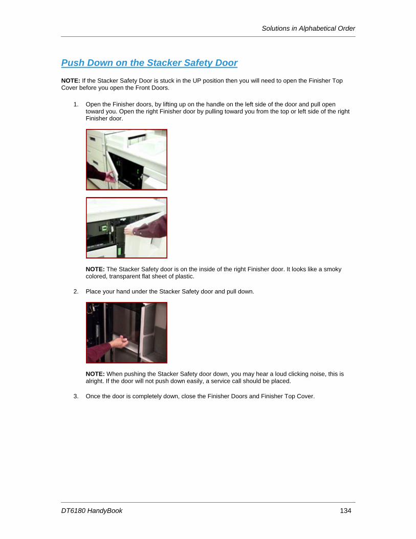
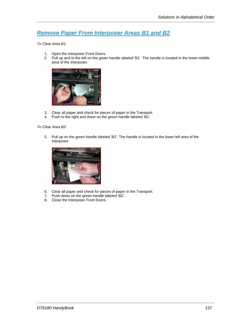
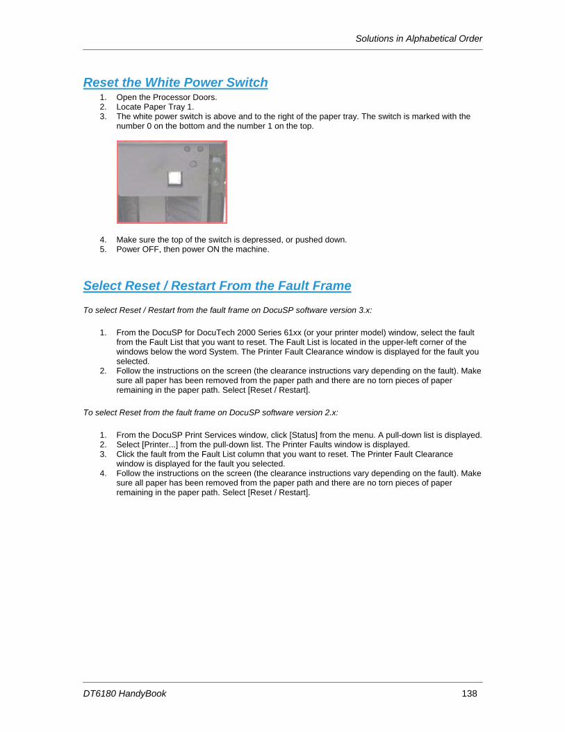
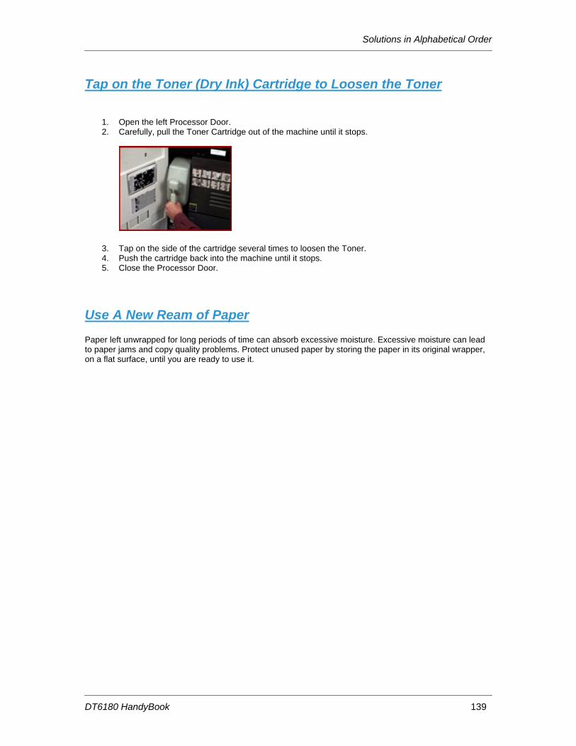
Clean the Bindexer Sensors (Q1205, Q1206, Q1207)............................................................... 74 Clean the Bins Exit Sensors (Q1222)......................................................................................... 75 Clean the Front Stack (Q1227), Rear Stack Height (Q1218), and Set Path (Q1221) Sensors . 77 Clean the Fuser (Q1010) and Prefuser Sensors (Q1009) ......................................................... 80 Clean the Post Inverter (Q1202) and Output Transport (Q1203) Sensors ................................ 82 Clean the Pre-Fuser Sensor (Q1009) ........................................................................................ 84 Clean the Registration Transport Sensor (Q861)....................................................................... 85 Clean the Set Path Sensor (Q1221)........................................................................................... 86 Clean the Tape Binder Area ....................................................................................................... 89 Clear Paper Jams in Areas 11, 12, 13, and 14 .......................................................................... 91 Clear Paper Jams in Areas 11, 12, and 13 ................................................................................ 94 Clear Paper Jams in Areas 13, 14, and 15 ................................................................................ 97 Clear Paper Jams in Areas 17 and 18 ..................................................................................... 100 Clear the Entire Paper Path From the Paper Trays to the Finisher ......................................... 102 Clear the Fault in the Printer Fault Clearance Window ............................................................ 102 Clear the Paper Jam in Area 4 ................................................................................................. 103 Clear the Paper Jam in Areas 11, 14, 17, and 18 .................................................................... 103 Clear the Paper Jam in Areas 12, 13, 14, and 15 .................................................................... 107 Clear the Paper Jam in Areas 3 and 4 ..................................................................................... 111 Clear the Paper Jam in Areas 5 and 6 ..................................................................................... 112 Clear the Paper Jam in Areas 7, 6, and 5 ................................................................................ 113 Clear the Paper Jam in Areas 8 and 9 ..................................................................................... 115 Clear the Paper Jam in Areas 8, 11, 12, and 13 ...................................................................... 116 Clear the Paper Jams in Areas 16 and 17 ............................................................................... 119 Clear the Paper Jams in Areas 17 and 19 ............................................................................... 121 Clear the Paper Jams in Areas 7, 6, 5, 4, and 2 ...................................................................... 123 Clear the Stitcher A Fault ......................................................................................................... 125 Fan the Paper, Turn the Paper Over, and Reload ................................................................... 127 If Paper is Jammed in the Fuser, Release the Camming Motor Brake.................................... 127 If Printing to the Edges of the Paper Stock, set Lead Edge Screening to Stress .................... 128 If the Job is Sent From a DigiPath, Clean the Document Glass on the DigiPath..................... 129 Lower the Decurler Baffle Above Area 7 .................................................................................. 129 Open and Close the Area 3 and 4 Baffles Securely................................................................. 130 Open and Close the Area 4 Baffle Securely............................................................................. 130 Open and Close the Area 9 Baffle Securely............................................................................. 131 Open and Close the Finisher Top Cover and the Finisher Front Doors................................... 131 Perform an Immediate Shutdown at the DocuSP..................................................................... 132 Power OFF, Reset the Printer Circuit Breakers, Then Power ON ........................................... 132 Power OFF, Then Power ON the Printer.................................................................................. 133 Push Down on the Stacker Safety Door................................................................................... 134 Read the Meter......................................................................................................................... 135 Release the Camming Motor Brake ......................................................................................... 135 Remove Paper From Interposer Areas B1 and B2................................................................... 137 Reset the White Power Switch ................................................................................................. 138 Select Reset / Restart From the Fault Frame........................................................................... 138 Tap on the Toner (Dry Ink) Cartridge to Loosen the Toner...................................................... 139 Use A New Ream of Paper ...................................................................................................... 139
7. Perform Printer Functions............................................... 141 1. Add a Font to the DocuSP Controller .................................................................................. 142 2. Allow Main, Aux, Auto, or Unspecified to be Used as Stock Names .................................. 143 3. Backup VIPP Files Before an Upgrade ............................................................................... 144 4. Check the Systems Queue Output Location and Finishing Selections............................... 145 5. Clear the Faulted Job .......................................................................................................... 146 6. Create a New Queue........................................................................................................... 147 7. Delete a Job in Job Manager............................................................................................... 148
DT6180 HandyBook
8. Disable Stock Size Checking............................................................................................... 149 9. Display all Active Machine Faults........................................................................................ 150 10. Enable and Bring On-line an External Finisher ................................................................. 151
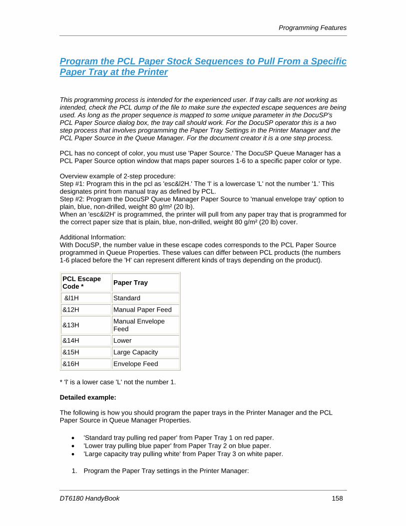
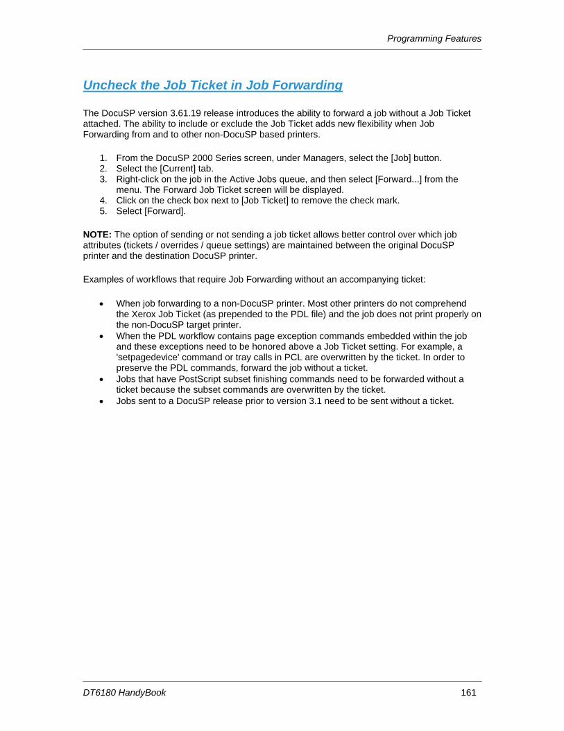
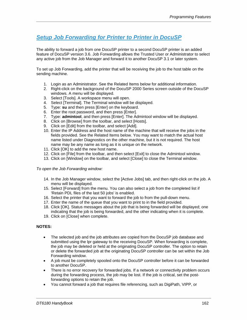
8. Programming Features.................................................... 153 Add Binding to a Job ................................................................................................................ 153 Enable Duplex Mode ................................................................................................................ 153 Enable Offset Stacking ............................................................................................................. 154 Export the Accounting Log ....................................................................................................... 155 Program Image Shift for a Job.................................................................................................. 156 Program Paper Tray 5 as a Non-Fusing Tray .......................................................................... 156 Program Tabs........................................................................................................................... 157 Program the PCL Paper Stock Sequences to Pull From a Specific Paper Tray at the Printer 158 Uncheck the Job Ticket in Job Forwarding .............................................................................. 161 Setup Job Forwarding for Printer to Printer in DocuSP............................................................ 162
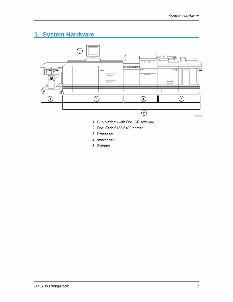
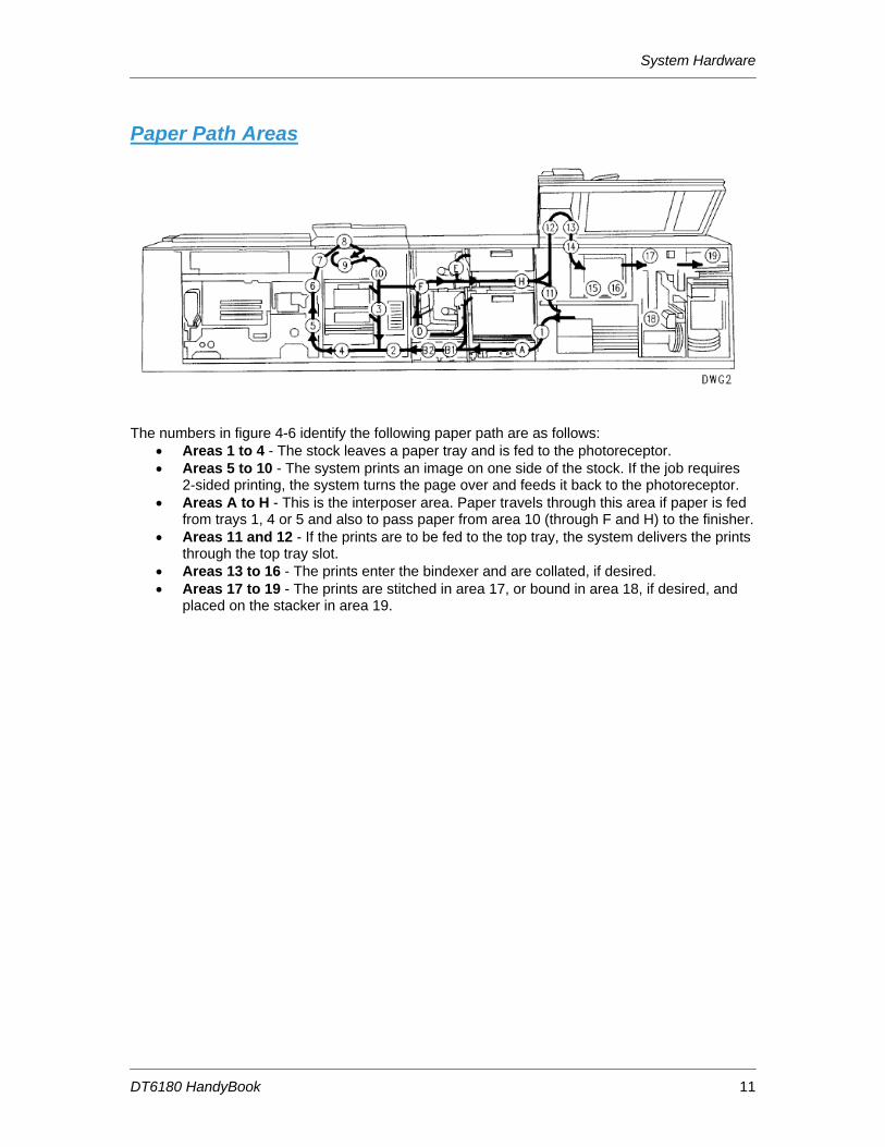
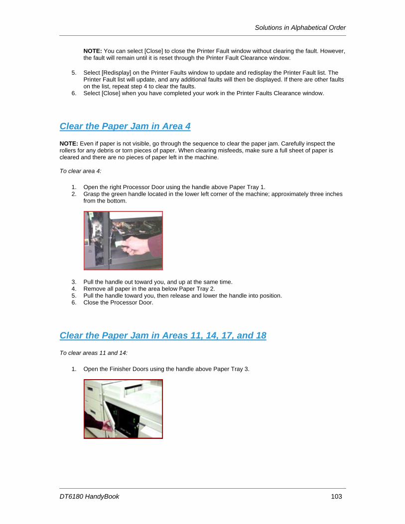
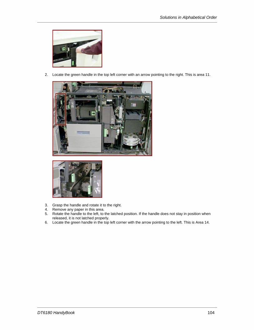
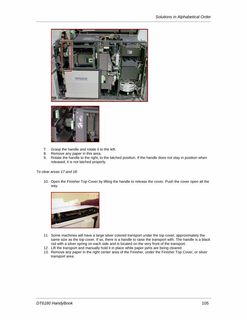
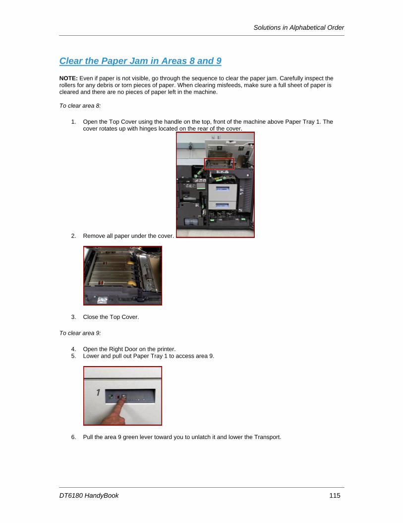
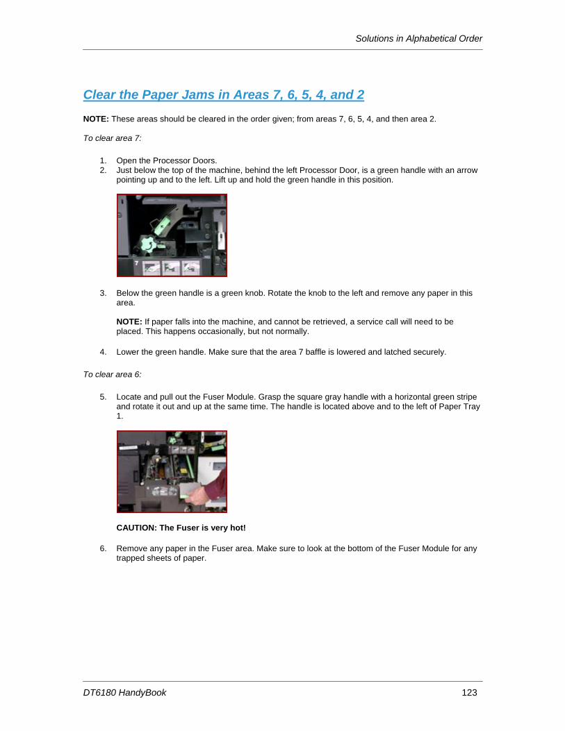
The numbers in figure 4-6 identify the following paper path are as follows:
• Areas 1 to 4 - The stock leaves a paper tray and is fed to the photoreceptor. • Areas 5 to 10 - The system prints an image on one side of the stock. If the job requires
2-sided printing, the system turns the page over and feeds it back to the photoreceptor. • Areas A to H - This is the interposer area. Paper travels through this area if paper is fed
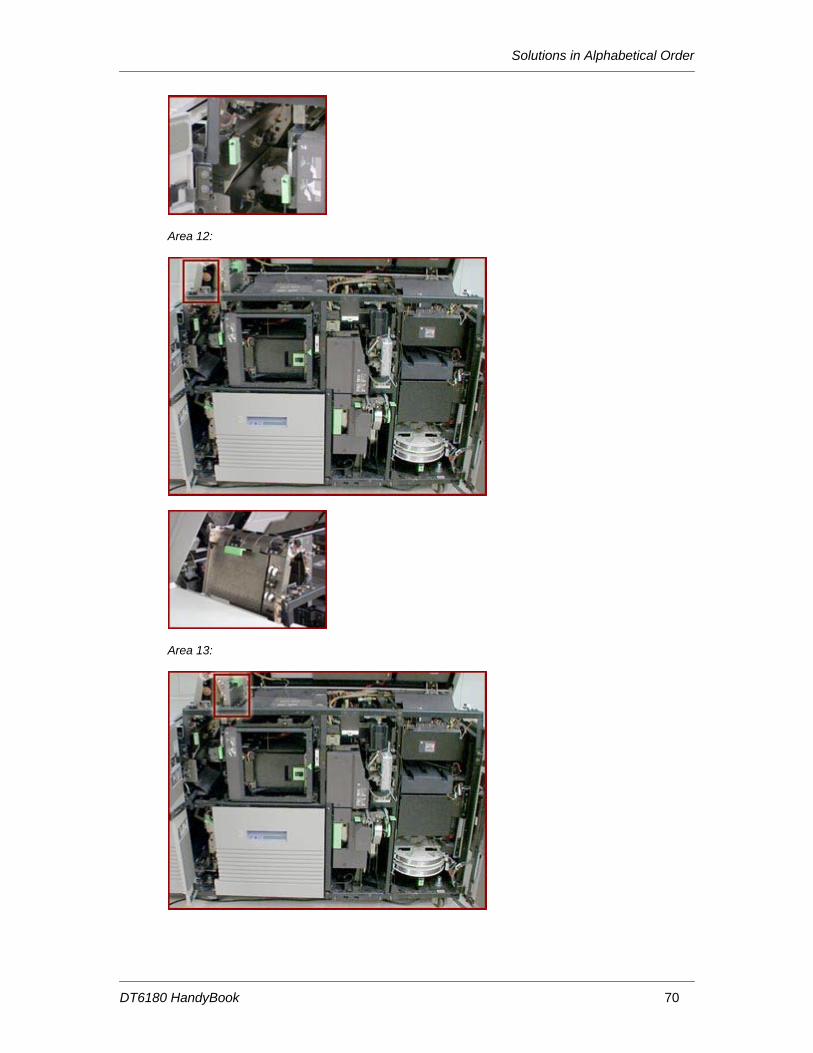
from trays 1, 4 or 5 and also to pass paper from area 10 (through F and H) to the finisher. • Areas 11 and 12 - If the prints are to be fed to the top tray, the system delivers the prints
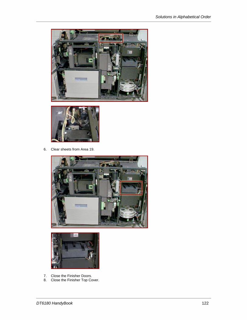
through the top tray slot. • Areas 13 to 16 - The prints enter the bindexer and are collated, if desired. • Areas 17 to 19 - The prints are stitched in area 17, or bound in area 18, if desired, and
placed on the stacker in area 19.
Paper Trays & Loading Media
DT6180 HandyBook 12
Paper Trays & Loading Media
DT6180 HandyBook 13
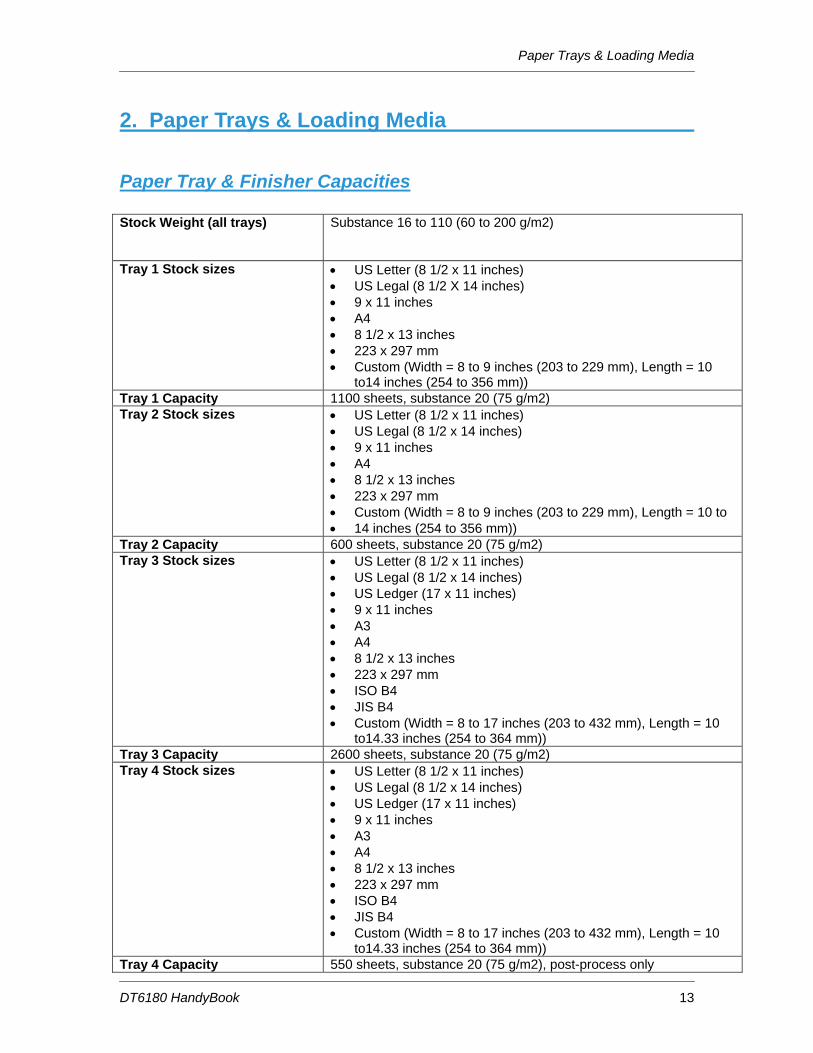
2. Paper Trays & Loading Media
Paper Tray & Finisher Capacities Stock Weight (all trays)
Substance 16 to 110 (60 to 200 g/m2)
Tray 1 Stock sizes
• US Letter (8 1/2 x 11 inches) • US Legal (8 1/2 X 14 inches) • 9 x 11 inches • A4 • 8 1/2 x 13 inches • 223 x 297 mm • Custom (Width = 8 to 9 inches (203 to 229 mm), Length = 10
• US Letter (8 1/2 x 11 inches) • US Legal (8 1/2 x 14 inches) • 9 x 11 inches • A4 • 8 1/2 x 13 inches • 223 x 297 mm • Custom (Width = 8 to 9 inches (203 to 229 mm), Length = 10 to • 14 inches (254 to 356 mm))
Tray 2 Capacity 600 sheets, substance 20 (75 g/m2) Tray 3 Stock sizes • US Letter (8 1/2 x 11 inches)
• US Legal (8 1/2 x 14 inches) • US Ledger (17 x 11 inches) • 9 x 11 inches • A3 • A4 • 8 1/2 x 13 inches • 223 x 297 mm • ISO B4 • JIS B4 • Custom (Width = 8 to 17 inches (203 to 432 mm), Length = 10
to14.33 inches (254 to 364 mm)) Tray 3 Capacity 2600 sheets, substance 20 (75 g/m2) Tray 4 Stock sizes • US Letter (8 1/2 x 11 inches)
• US Legal (8 1/2 x 14 inches) • US Ledger (17 x 11 inches) • 9 x 11 inches • A3 • A4 • 8 1/2 x 13 inches • 223 x 297 mm • ISO B4 • JIS B4 • Custom (Width = 8 to 17 inches (203 to 432 mm), Length = 10
to14.33 inches (254 to 364 mm)) Tray 4 Capacity 550 sheets, substance 20 (75 g/m2), post-process only
Paper Trays & Loading Media
DT6180 HandyBook 14
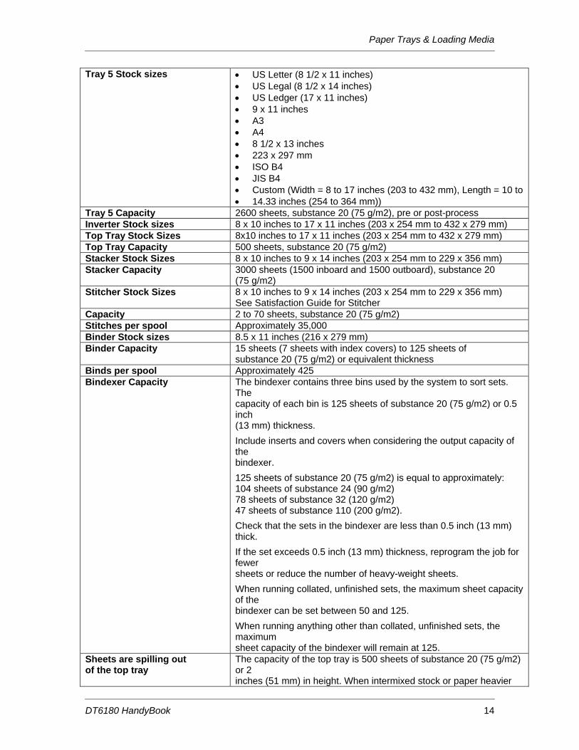
Tray 5 Stock sizes • US Letter (8 1/2 x 11 inches) • US Legal (8 1/2 x 14 inches) • US Ledger (17 x 11 inches) • 9 x 11 inches • A3 • A4 • 8 1/2 x 13 inches • 223 x 297 mm • ISO B4 • JIS B4 • Custom (Width = 8 to 17 inches (203 to 432 mm), Length = 10 to • 14.33 inches (254 to 364 mm))
Tray 5 Capacity 2600 sheets, substance 20 (75 g/m2), pre or post-process Inverter Stock sizes 8 x 10 inches to 17 x 11 inches (203 x 254 mm to 432 x 279 mm) Top Tray Stock Sizes 8x10 inches to 17 x 11 inches (203 x 254 mm to 432 x 279 mm) Top Tray Capacity 500 sheets, substance 20 (75 g/m2) Stacker Stock Sizes 8 x 10 inches to 9 x 14 inches (203 x 254 mm to 229 x 356 mm) Stacker Capacity 3000 sheets (1500 inboard and 1500 outboard), substance 20
(75 g/m2) Stitcher Stock Sizes 8 x 10 inches to 9 x 14 inches (203 x 254 mm to 229 x 356 mm)
See Satisfaction Guide for Stitcher Capacity 2 to 70 sheets, substance 20 (75 g/m2) Stitches per spool Approximately 35,000 Binder Stock sizes 8.5 x 11 inches (216 x 279 mm) Binder Capacity 15 sheets (7 sheets with index covers) to 125 sheets of
substance 20 (75 g/m2) or equivalent thickness Binds per spool Approximately 425 Bindexer Capacity The bindexer contains three bins used by the system to sort sets.
The capacity of each bin is 125 sheets of substance 20 (75 g/m2) or 0.5 inch (13 mm) thickness.
Include inserts and covers when considering the output capacity of the bindexer.
125 sheets of substance 20 (75 g/m2) is equal to approximately: 104 sheets of substance 24 (90 g/m2) 78 sheets of substance 32 (120 g/m2) 47 sheets of substance 110 (200 g/m2).
Check that the sets in the bindexer are less than 0.5 inch (13 mm) thick.
If the set exceeds 0.5 inch (13 mm) thickness, reprogram the job for fewer sheets or reduce the number of heavy-weight sheets.
When running collated, unfinished sets, the maximum sheet capacity of the bindexer can be set between 50 and 125.
When running anything other than collated, unfinished sets, the maximum sheet capacity of the bindexer will remain at 125.
Sheets are spilling out of the top tray
The capacity of the top tray is 500 sheets of substance 20 (75 g/m2) or 2 inches (51 mm) in height. When intermixed stock or paper heavier
Paper Trays & Loading Media
DT6180 HandyBook 15
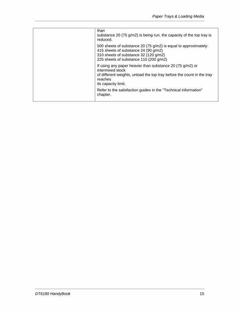
than substance 20 (75 g/m2) is being run, the capacity of the top tray is reduced.
500 sheets of substance 20 (75 g/m2) is equal to approximately: 415 sheets of substance 24 (90 g/m2) 310 sheets of substance 32 (120 g/m2) 225 sheets of substance 110 (200 g/m2)
If using any paper heavier than substance 20 (75 g/m2) or intermixed stock of different weights, unload the top tray before the count in the tray reaches its capacity limit.
Refer to the satisfaction guides in the "Technical information" chapter.
Paper Trays & Loading Media
DT6180 HandyBook 16
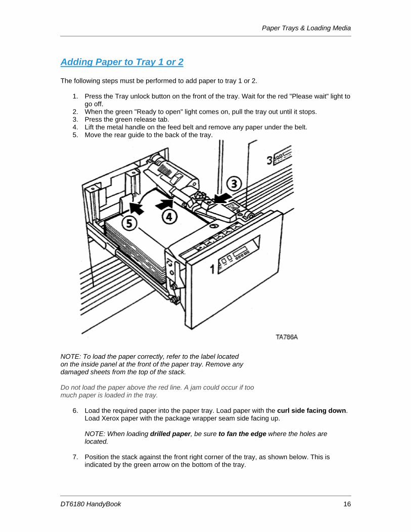
Adding Paper to Tray 1 or 2 The following steps must be performed to add paper to tray 1 or 2.
1. Press the Tray unlock button on the front of the tray. Wait for the red "Please wait" light to go off.
2. When the green "Ready to open" light comes on, pull the tray out until it stops. 3. Press the green release tab. 4. Lift the metal handle on the feed belt and remove any paper under the belt. 5. Move the rear guide to the back of the tray.
NOTE: To load the paper correctly, refer to the label located on the inside panel at the front of the paper tray. Remove any damaged sheets from the top of the stack. Do not load the paper above the red line. A jam could occur if too much paper is loaded in the tray.
6. Load the required paper into the paper tray. Load paper with the curl side facing down. Load Xerox paper with the package wrapper seam side facing up.
NOTE: When loading drilled paper, be sure to fan the edge where the holes are located.
7. Position the stack against the front right corner of the tray, as shown below. This is
indicated by the green arrow on the bottom of the tray.
Paper Trays & Loading Media
DT6180 HandyBook 17
Move the rear guide forward until it touches the edge of the stack. Lower the feed belt. Close the tray slowly, but firmly, until it latches.
Paper Trays & Loading Media
DT6180 HandyBook 18
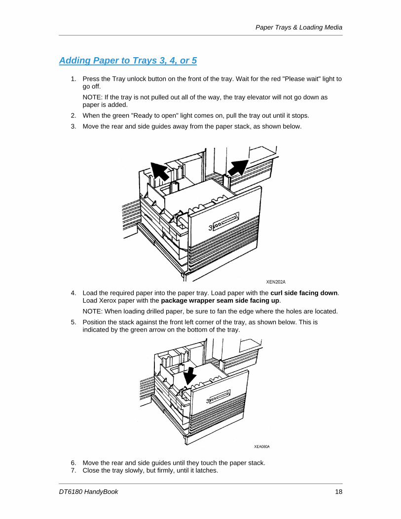
Adding Paper to Trays 3, 4, or 5
1. Press the Tray unlock button on the front of the tray. Wait for the red "Please wait" light to go off. NOTE: If the tray is not pulled out all of the way, the tray elevator will not go down as paper is added.
2. When the green "Ready to open" light comes on, pull the tray out until it stops. 3. Move the rear and side guides away from the paper stack, as shown below.
4. Load the required paper into the paper tray. Load paper with the curl side facing down.
Load Xerox paper with the package wrapper seam side facing up. NOTE: When loading drilled paper, be sure to fan the edge where the holes are located.
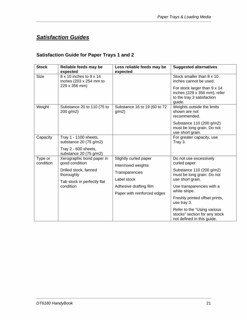
5. Position the stack against the front left corner of the tray, as shown below. This is indicated by the green arrow on the bottom of the tray.
6. Move the rear and side guides until they touch the paper stack. 7. Close the tray slowly, but firmly, until it latches.
Paper Trays & Loading Media
DT6180 HandyBook 19
Loading Transparencies The following are the different types and usage of transparencies for Paper Trays 1, 2 and 3.
• Transparencies with a 13 mm (0.5 inch) white stripe should be loaded with the white stripe to the right if you are using Paper Trays 1 and 2. Load the shiny side up for optimum performance.
• Removable stripe transparencies: Do not load more than 50 removable-stripe transparencies into Paper Trays 1 and 2. With the white stripe to the right, place the transparencies on top of approximately 50 sheets of paper in the tray. Do not run as inserts to a bound job. Printing is not allowed on inserts.
• High speed transparencies with paper backing: Run these types of transparencies from Paper Trays 1 and 2 with the paper side down, and from Paper Tray 3 with the paper side up.
Re-Loading Tabs For DocuSP version 3.X or higher: There are two methods to replenish tab stock in the paper trays. Option 1:
1. Open the paper tray where the tab stock is loaded. 2. Remove any tabs so that there is a full bank of tabs on top of the stack. 3. Add additional tab stock. 4. Close the paper tray.
Option 2:
1. Open the paper tray where the tab stock is loaded. 2. Add additional tab stock to the bottom of stack. 3. From the DocuSP for DocuTech 2000 series 61XX screen, select [Printer Manager].
Information about each paper tray will be displayed. 4. Select the line that has the information about the paper tray you are adding tab stock to.
A menu will be displayed. 5. Select [Properties] from the menu. The Tray Properties window will be displayed. 6. Select the check box next to [Set Sequence Position]. The box below the Set Sequence
Position box will become active. 7. Enter the number of tabs remaining in the bank of tabs on top of the stack in the paper
tray. For example, if there are three tabs remaining on top of the stack in the tray, enter the number [3] in this box.
8. Select the check box next to [Check Override Programming] in the lower, left corner of the window.
9. Select [OK]. 10. Close the paper tray.
For DocuSP version 2.X or lower: 1. Open the paper tray where the tab stock is loaded. 2. Remove any tabs so that there is a full bank on top of the stack. 3. Add additional tab stock. 4. Close the paper tray.
Paper Trays & Loading Media
DT6180 HandyBook 20
Adding Inserts
For DocuSP 4.x and above:
Creating inserts differs from slip sheets in that they separate pages of a job while slip sheets separate one job from another. Inserts may also be pre-printed stock or forms.
NOTE: Inserts may not be programmed for a job with covers if the inserts affect the cover printing. For example, inserts are not allowed between pages printed on the front and back of a cover. An insert request takes precedence over an exception page request. When two or more special pages are programmed (covers, inserts, or exception pages) image ordering conflicts may occur. Make sure that programmed options do not conflict.
1. From the DocuSP screen, logon as a System Administrator. See the Related Items below for additional information.
2. Under Managers on the left, under the Job button, right-click on your job and select [Properties] from the menu.
3. Click on the [Special Pages] tab. 4. Click on the [Inserts] button, and then click on [Add Inserts] button. The Insert screen will
be displayed. 5. If the insert is to be the first page, enter 0 (zero) in the After Pages field, and then the
number of inserts required in the Pages field. The result will be the insert being the first page in the job.
6. Click on the [Add Insert] button. 7. Click on [Close]. 8. Click [OK].
Paper Trays & Loading Media
DT6180 HandyBook 21
Satisfaction Guides
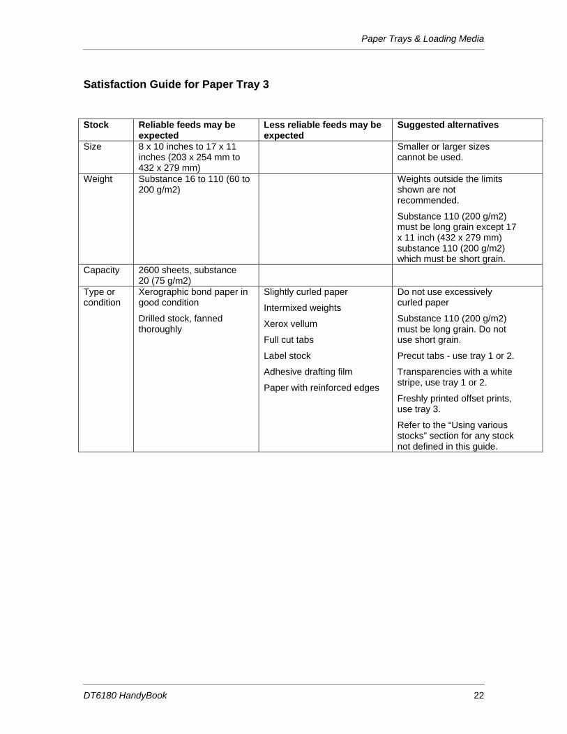
Satisfaction Guide for Paper Trays 1 and 2 Stock Reliable feeds may be
expected Less reliable feeds may be expected
Suggested alternatives
Size 8 x 10 inches to 9 x 14 inches (203 x 254 mm to 229 x 356 mm)
Stock smaller than 8 x 10 inches cannot be used.
For stock larger than 9 x 14 inches (229 x 356 mm), refer to the tray 3 satisfaction guide.
Weight Substance 20 to 110 (75 to 200 g/m2)
Substance 16 to 19 (60 to 72 g/m2)
Weights outside the limits shown are not recommended.
Substance 110 (200 g/m2) must be long grain. Do not use short grain.
Capacity
Tray 1 - 1100 sheets, substance 20 (75 g/m2)
Tray 2 - 600 sheets, substance 20 (75 g/m2)
For greater capacity, use Tray 3.
Type or condition
Xerographic bond paper in good condition
Drilled stock, fanned thoroughly
Tab stock in perfectly flat condition
Slightly curled paper
Intermixed weights
Transparencies
Label stock
Adhesive drafting film
Paper with reinforced edges
Do not use excessively curled paper
Substance 110 (200 g/m2) must be long grain. Do not use short grain.
Use transparencies with a white stripe.
Freshly printed offset prints, use tray 3.
Refer to the “Using various stocks” section for any stock not defined in this guide.
Paper Trays & Loading Media
DT6180 HandyBook 22
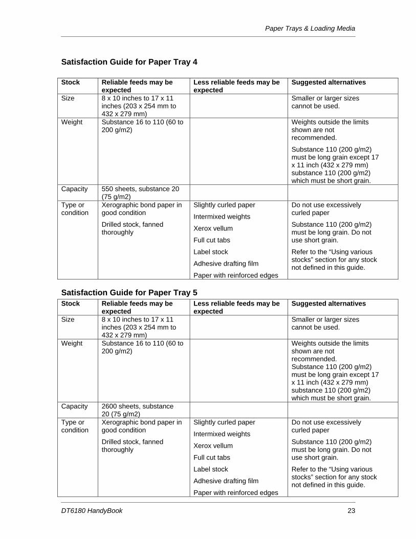
Satisfaction Guide for Paper Tray 3 Stock Reliable feeds may be
expected Less reliable feeds may be expected
Suggested alternatives
Size 8 x 10 inches to 17 x 11 inches (203 x 254 mm to 432 x 279 mm)
Smaller or larger sizes cannot be used.
Weight Substance 16 to 110 (60 to 200 g/m2)
Weights outside the limits shown are not recommended.
Substance 110 (200 g/m2) must be long grain except 17 x 11 inch (432 x 279 mm) substance 110 (200 g/m2) which must be short grain.
Capacity
2600 sheets, substance 20 (75 g/m2)
Type or condition
Xerographic bond paper in good condition
Drilled stock, fanned thoroughly
Slightly curled paper
Intermixed weights
Xerox vellum
Full cut tabs
Label stock
Adhesive drafting film
Paper with reinforced edges
Do not use excessively curled paper
Substance 110 (200 g/m2) must be long grain. Do not use short grain.
Precut tabs - use tray 1 or 2.
Transparencies with a white stripe, use tray 1 or 2.
Freshly printed offset prints, use tray 3.
Refer to the “Using various stocks” section for any stock not defined in this guide.
Paper Trays & Loading Media
DT6180 HandyBook 23
Satisfaction Guide for Paper Tray 4 Stock Reliable feeds may be
expected Less reliable feeds may be expected
Suggested alternatives
Size 8 x 10 inches to 17 x 11 inches (203 x 254 mm to 432 x 279 mm)
Smaller or larger sizes cannot be used.
Weight Substance 16 to 110 (60 to 200 g/m2)
Weights outside the limits shown are not recommended.
Substance 110 (200 g/m2) must be long grain except 17 x 11 inch (432 x 279 mm) substance 110 (200 g/m2) which must be short grain.
Capacity
550 sheets, substance 20 (75 g/m2)
Type or condition
Xerographic bond paper in good condition
Drilled stock, fanned thoroughly
Slightly curled paper
Intermixed weights
Xerox vellum
Full cut tabs
Label stock
Adhesive drafting film
Paper with reinforced edges
Do not use excessively curled paper
Substance 110 (200 g/m2) must be long grain. Do not use short grain.
Refer to the “Using various stocks” section for any stock not defined in this guide.
Satisfaction Guide for Paper Tray 5 Stock Reliable feeds may be
expected Less reliable feeds may be expected
Suggested alternatives
Size 8 x 10 inches to 17 x 11 inches (203 x 254 mm to 432 x 279 mm)
Smaller or larger sizes cannot be used.
Weight Substance 16 to 110 (60 to 200 g/m2)
Weights outside the limits shown are not recommended. Substance 110 (200 g/m2) must be long grain except 17 x 11 inch (432 x 279 mm) substance 110 (200 g/m2) which must be short grain.
Capacity 2600 sheets, substance 20 (75 g/m2)
Type or condition
Xerographic bond paper in good condition
Drilled stock, fanned thoroughly
Slightly curled paper
Intermixed weights
Xerox vellum
Full cut tabs
Label stock
Adhesive drafting film
Paper with reinforced edges
Do not use excessively curled paper
Substance 110 (200 g/m2) must be long grain. Do not use short grain.
Refer to the “Using various stocks” section for any stock not defined in this guide.
Paper Trays & Loading Media
DT6180 HandyBook 24
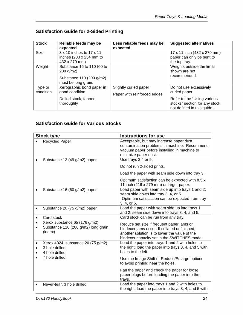
Satisfaction Guide for 2-Sided Printing Stock Reliable feeds may be
expected Less reliable feeds may be expected
Suggested alternatives
Size 8 x 10 inches to 17 x 11 inches (203 x 254 mm to 432 x 279 mm)
17 x 11 inch (432 x 279 mm) paper can only be sent to the top tray.
Weight Substance 16 to 110 (60 to 200 g/m2)
Substance 110 (200 g/m2) must be long grain.
Weights outside the limits shown are not recommended.
Type or condition
Xerographic bond paper in good condition
Drilled stock, fanned thoroughly
Slightly curled paper
Paper with reinforced edges
Do not use excessively curled paper
Refer to the “Using various stocks” section for any stock not defined in this guide.
Satisfaction Guide for Various Stocks Stock type Instructions for use • Recycled Paper Acceptable, but may increase paper dust
contamination problems in machine. Recommend vacuum paper before installing in machine to minimize paper dust.
• Substance 13 (49 g/m2) paper Use trays 3,4,or 5.
Do not run 2-sided prints.
Load the paper with seam side down into tray 3.
Optimum satisfaction can be expected with 8.5 x 11 inch (216 x 279 mm) or larger paper.
• Substance 16 (60 g/m2) paper Load paper with seam side up into trays 1 and 2; seam side down into tray 3, 4, or 5. Optimum satisfaction can be expected from tray 3, 4, or 5.
• Substance 20 (75 g/m2) paper Load the paper with seam side up into trays 1 and 2; seam side down into trays 3, 4, and 5.
Reduce set size if frequent paper jams or bindexer jams occur. If collated unfinished, another solution is to lower the value of the bindexer capacity set in the SWITCHES mode.
Load the paper into trays 1 and 2 with holes to the right; load the paper into trays 3, 4, and 5 with holes to the left.
Use the Image Shift or Reduce/Enlarge options to avoid printing near the holes.
Fan the paper and check the paper for loose paper plugs before loading the paper into the trays.
• Never-tear, 3 hole drilled Load the paper into trays 1 and 2 with holes to the right; load the paper into trays 3, 4, and 5 with
Paper Trays & Loading Media
DT6180 HandyBook 25
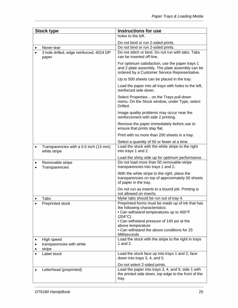
Stock type Instructions for use holes to the left.
Do not bind or run 2-sided prints. • Never-tear Do not bind or run 2-sided prints. • 3 hole drilled, edge reinforced, 4024 DP
paper Do not stitch or bind. Do not run with tabs. Tabs can be inserted off-line.
For optimum satisfaction, use the paper trays 1 and 2 plate assembly. The plate assembly can be ordered by a Customer Service Representative.
Up to 500 sheets can be placed in the tray.
Load the paper into all trays with holes to the left, reinforced side down.
Select Properties... on the Trays pull-down menu. On the Stock window, under Type, select Drilled.
Image quality problems may occur near the reinforcement with side 2 printing.
Remove the paper immediately before use to ensure that prints stay flat.
Print with no more than 200 sheets in a tray.
Select a quantity of 50 or fewer at a time. • Transparencies with a 0.5 inch (13 mm)
white stripe Load the stock with the white stripe to the right into trays 1 and 2.
Load the shiny side up for optimum performance. • Removable stripe • Transparencies
Do not load more than 50 removable-stripe transparencies into trays 1 and 2.
With the white stripe to the right, place the transparencies on top of approximately 50 sheets of paper in the tray.
Do not run as inserts to a bound job. Printing is not allowed on inserts.
• Tabs Mylar tabs should be run out of tray 4. • Preprinted stock Preprinted forms must be made up of ink that has
the following characteristics: • Can withstand temperatures up to 400°F (204°C) • Can withstand pressure of 140 psi at the above temperature • Can withstand the above conditions for 25 Milliseconds
• High speed • transparencies with white • stripe
Load the stock with the stripe to the right in trays 1 and 2.
• Label stock Load the stock face up into trays 1 and 2; face down into trays 3, 4, and 5.
Do not select 2-sided prints. • Letterhead (preprinted) Load the paper into trays 3, 4, and 5; side 1 with
the printed side down, top edge to the front of the tray.
Paper Trays & Loading Media
DT6180 HandyBook 26
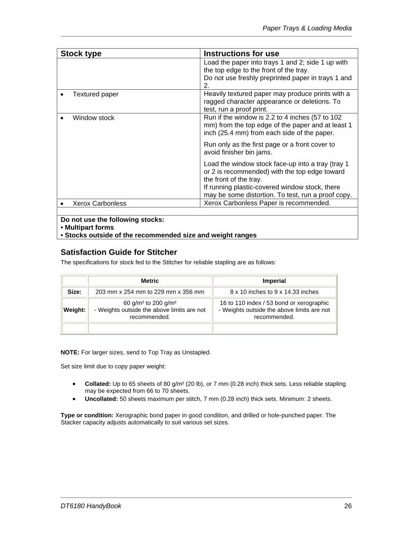
Stock type Instructions for use Load the paper into trays 1 and 2; side 1 up with the top edge to the front of the tray. Do not use freshly preprinted paper in trays 1 and 2.
• Textured paper Heavily textured paper may produce prints with a ragged character appearance or deletions. To test, run a proof print.
• Window stock Run if the window is 2.2 to 4 inches (57 to 102 mm) from the top edge of the paper and at least 1 inch (25.4 mm) from each side of the paper.
Run only as the first page or a front cover to avoid finisher bin jams.
Load the window stock face-up into a tray (tray 1 or 2 is recommended) with the top edge toward the front of the tray. If running plastic-covered window stock, there may be some distortion. To test, run a proof copy.
• Xerox Carbonless Xerox Carbonless Paper is recommended. Do not use the following stocks: • Multipart forms • Stocks outside of the recommended size and weight ranges
Satisfaction Guide for Stitcher The specifications for stock fed to the Stitcher for reliable stapling are as follows:
Metric Imperial
Size: 203 mm x 254 mm to 229 mm x 356 mm 8 x 10 inches to 9 x 14.33 inches
Weight: 60 g/m² to 200 g/m²
- Weights outside the above limits are not recommended.
16 to 110 index / 53 bond or xerographic - Weights outside the above limits are not
recommended.
NOTE: For larger sizes, send to Top Tray as Unstapled. Set size limit due to copy paper weight:
• Collated: Up to 65 sheets of 80 g/m² (20 lb), or 7 mm (0.28 inch) thick sets. Less reliable stapling may be expected from 66 to 70 sheets.
• Uncollated: 50 sheets maximum per stitch, 7 mm (0.28 inch) thick sets. Minimum: 2 sheets.
Type or condition: Xerographic bond paper in good condition, and drilled or hole-punched paper. The Stacker capacity adjusts automatically to suit various set sizes.
Recommended Shift Preventative Maintenance Plan
DT6180 HandyBook 27
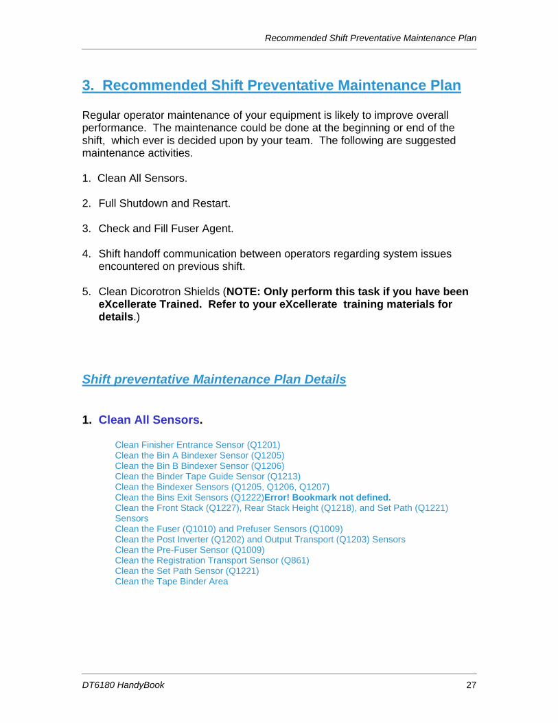
3. Recommended Shift Preventative Maintenance Plan Regular operator maintenance of your equipment is likely to improve overall performance. The maintenance could be done at the beginning or end of the shift, which ever is decided upon by your team. The following are suggested maintenance activities. 1. Clean All Sensors. 2. Full Shutdown and Restart. 3. Check and Fill Fuser Agent. 4. Shift handoff communication between operators regarding system issues
encountered on previous shift. 5. Clean Dicorotron Shields (NOTE: Only perform this task if you have been
eXcellerate Trained. Refer to your eXcellerate training materials for details.)
Shift preventative Maintenance Plan Details
1. Clean All Sensors. Clean Finisher Entrance Sensor (Q1201) Clean the Bin A Bindexer Sensor (Q1205) Clean the Bin B Bindexer Sensor (Q1206) Clean the Binder Tape Guide Sensor (Q1213) Clean the Bindexer Sensors (Q1205, Q1206, Q1207) Clean the Bins Exit Sensors (Q1222)Error! Bookmark not defined. Clean the Front Stack (Q1227), Rear Stack Height (Q1218), and Set Path (Q1221) Sensors Clean the Fuser (Q1010) and Prefuser Sensors (Q1009) Clean the Post Inverter (Q1202) and Output Transport (Q1203) Sensors Clean the Pre-Fuser Sensor (Q1009) Clean the Registration Transport Sensor (Q861) Clean the Set Path Sensor (Q1221) Clean the Tape Binder Area
Recommended Shift Preventative Maintenance Plan
DT6180 HandyBook 28
2. Shut Down, Then Start Up the System, Then Power On the Printer WARNING: Powering OFF the System, and thus the printer will result in the loss of all jobs in the print queue. Under normal operating conditions, use the DocuSP Controller software to power OFF the machine. NOTE: If jobs are currently printing or waiting to print, they should be placed on hold before you power OFF the System and the printer. You must be logged on as a System Administrator or Trusted User to place a job on hold. To Shut Down and Start Up the System:
1. Make sure that the “System Administrator” is logged in on the machine. 2. In the DocuSP [System Menu], on the walk up dialog frame, select [Shutdown]. 3. Select the [Yes] confirmation button. 4. Allow the system to shut down. 5. In the Solaris command line type [boot] and hit the [return] key. 6. Ignore the various messages displayed on the monitor as the machine boots up.
To power ON the printer:
1. Make sure that the “System Administrator” is logged in on the machine. 2. In the Print Manager window, select [Printer] from the toolbar. A menu will be displayed. 3. Select [Printer On] from the menu.
The printer that your Controller is attached to will be powered ON. This process will happen without a confirmation window.
3. Check and Fill Fuser Agent. See 4. Replacing Consumables: Add Fuser Agent page 27.
4. Shift handoff communication between operators regarding system issues encountered on previous shift.
5. Clean Dicorotron Shields (NOTE: Only perform this task if you have been eXcellerate Trained. Refer to your eXcellerate training materials for details.)
Replacing Consumables
DT6180 HandyBook 29
4. Replacing Consumables
Add Fuser Agent NOTE: You should add Fuser Agent as soon as possible after the message is displayed. If Fuser Agent is not added the machine will stop running after approximately 5,000 prints and will not run until Fuser Agent is added. To add Fuser Agent:
1. Open the Processor Doors. 2. Place a drop cloth on the floor under the Fuser area to catch any Fuser Agent that may
spill. WARNING: The Fuser area can reach temperatures of approximately 425 ° F / 218 ° C. Use extreme care to prevent burns when working in this area.
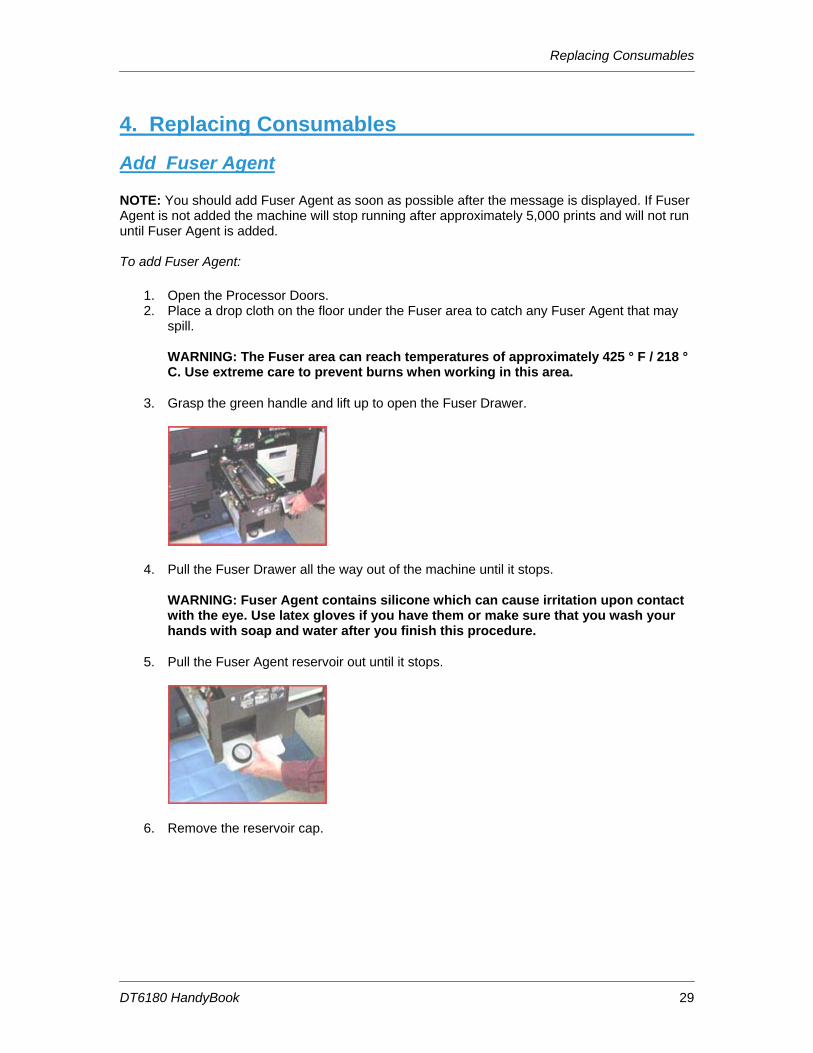
3. Grasp the green handle and lift up to open the Fuser Drawer.
4. Pull the Fuser Drawer all the way out of the machine until it stops. WARNING: Fuser Agent contains silicone which can cause irritation upon contact with the eye. Use latex gloves if you have them or make sure that you wash your hands with soap and water after you finish this procedure.
5. Pull the Fuser Agent reservoir out until it stops.
6. Remove the reservoir cap.
Replacing Consumables
DT6180 HandyBook 30
7. Open a new box of Fuser Agent and remove the bottle. CAUTION: Make sure you use the Fuser Agent specific to the machine model you are using. Fuser Agent for the machine model DocuTech 90 is not compatible with the DocuTech 135.
8. Remove the cap from the bottle of the Fuser Agent. 9. Carefully pour the Fuser Agent into the reservoir until the level reaches the Max line.
CAUTION: There is an anti-splash seal in the reservoir. To avoid damage to this seal, do not push the Fuser Agent bottle into the reservoir with excessive force. WARNING: If any Fuser Agent is spilled onto the floor, it must be removed immediately as the floor can become slippery.
10. Replace the reservoir cap. 11. Push the Fuser Agent reservoir in to the machine until it stops. 12. Push the Fuser Drawer all the way into the machine until the drawer latches into place. 13. Close the Processor Doors. The Fuser Agent message will disappear after approximately
20 prints are made.
Replacing Consumables
DT6180 HandyBook 31
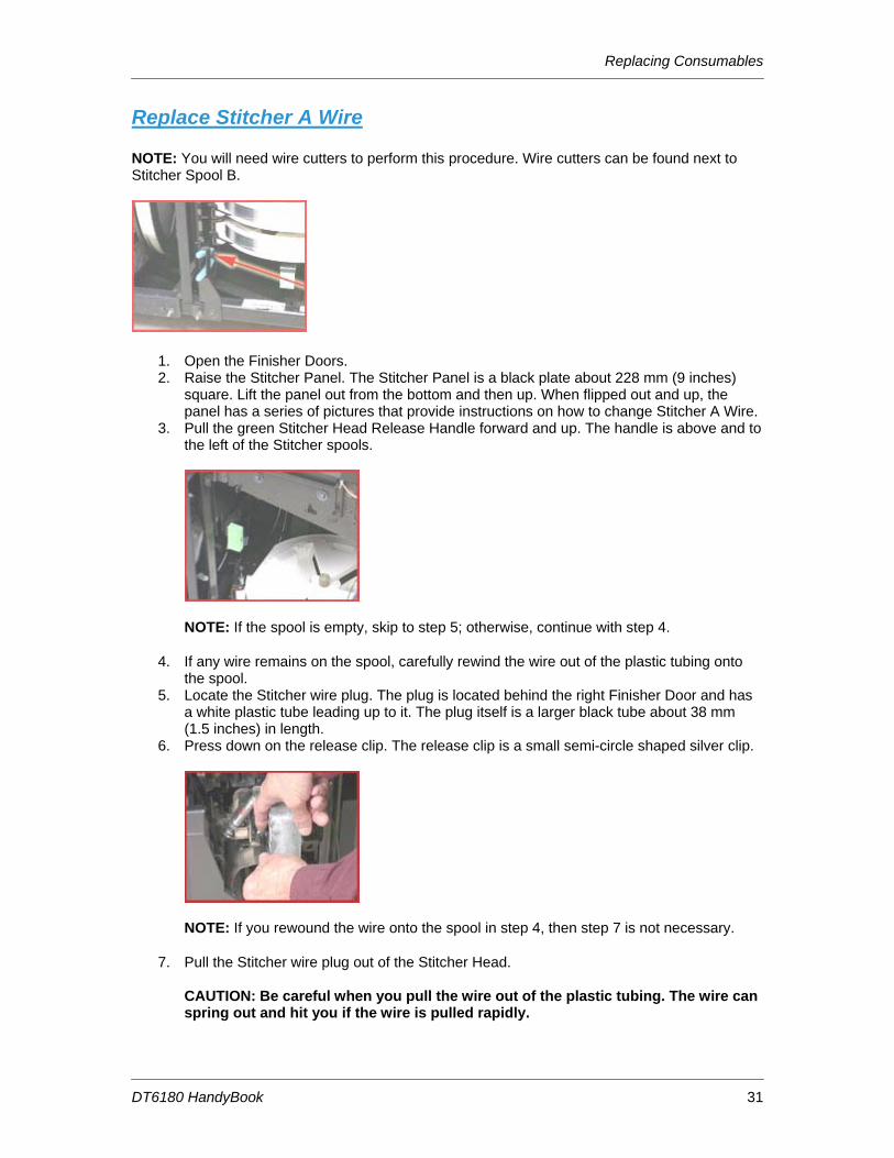
Replace Stitcher A Wire NOTE: You will need wire cutters to perform this procedure. Wire cutters can be found next to Stitcher Spool B.
1. Open the Finisher Doors. 2. Raise the Stitcher Panel. The Stitcher Panel is a black plate about 228 mm (9 inches)
square. Lift the panel out from the bottom and then up. When flipped out and up, the panel has a series of pictures that provide instructions on how to change Stitcher A Wire.
3. Pull the green Stitcher Head Release Handle forward and up. The handle is above and to the left of the Stitcher spools.
NOTE: If the spool is empty, skip to step 5; otherwise, continue with step 4.
4. If any wire remains on the spool, carefully rewind the wire out of the plastic tubing onto the spool.
5. Locate the Stitcher wire plug. The plug is located behind the right Finisher Door and has a white plastic tube leading up to it. The plug itself is a larger black tube about 38 mm (1.5 inches) in length.
6. Press down on the release clip. The release clip is a small semi-circle shaped silver clip.
NOTE: If you rewound the wire onto the spool in step 4, then step 7 is not necessary.
7. Pull the Stitcher wire plug out of the Stitcher Head. CAUTION: Be careful when you pull the wire out of the plastic tubing. The wire can spring out and hit you if the wire is pulled rapidly.
Replacing Consumables
DT6180 HandyBook 32
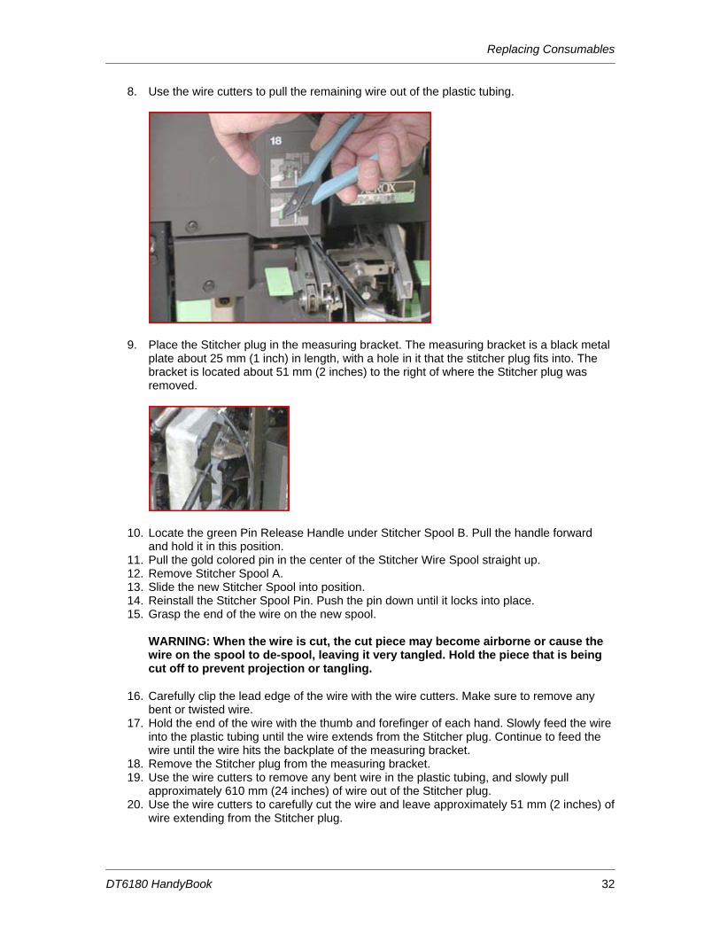
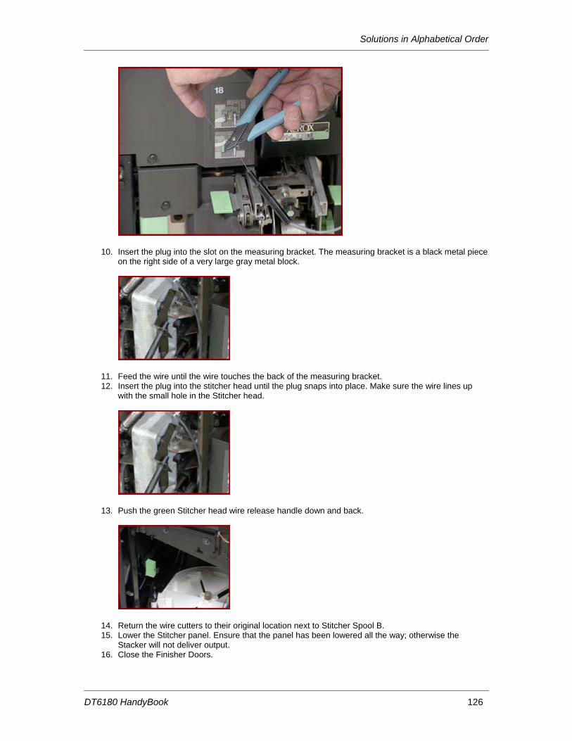
8. Use the wire cutters to pull the remaining wire out of the plastic tubing.
9. Place the Stitcher plug in the measuring bracket. The measuring bracket is a black metal plate about 25 mm (1 inch) in length, with a hole in it that the stitcher plug fits into. The bracket is located about 51 mm (2 inches) to the right of where the Stitcher plug was removed.
10. Locate the green Pin Release Handle under Stitcher Spool B. Pull the handle forward and hold it in this position.
11. Pull the gold colored pin in the center of the Stitcher Wire Spool straight up. 12. Remove Stitcher Spool A. 13. Slide the new Stitcher Spool into position. 14. Reinstall the Stitcher Spool Pin. Push the pin down until it locks into place. 15. Grasp the end of the wire on the new spool.
WARNING: When the wire is cut, the cut piece may become airborne or cause the wire on the spool to de-spool, leaving it very tangled. Hold the piece that is being cut off to prevent projection or tangling.
16. Carefully clip the lead edge of the wire with the wire cutters. Make sure to remove any bent or twisted wire.
17. Hold the end of the wire with the thumb and forefinger of each hand. Slowly feed the wire into the plastic tubing until the wire extends from the Stitcher plug. Continue to feed the wire until the wire hits the backplate of the measuring bracket.
18. Remove the Stitcher plug from the measuring bracket. 19. Use the wire cutters to remove any bent wire in the plastic tubing, and slowly pull
approximately 610 mm (24 inches) of wire out of the Stitcher plug. 20. Use the wire cutters to carefully cut the wire and leave approximately 51 mm (2 inches) of
wire extending from the Stitcher plug.
Replacing Consumables
DT6180 HandyBook 33
>
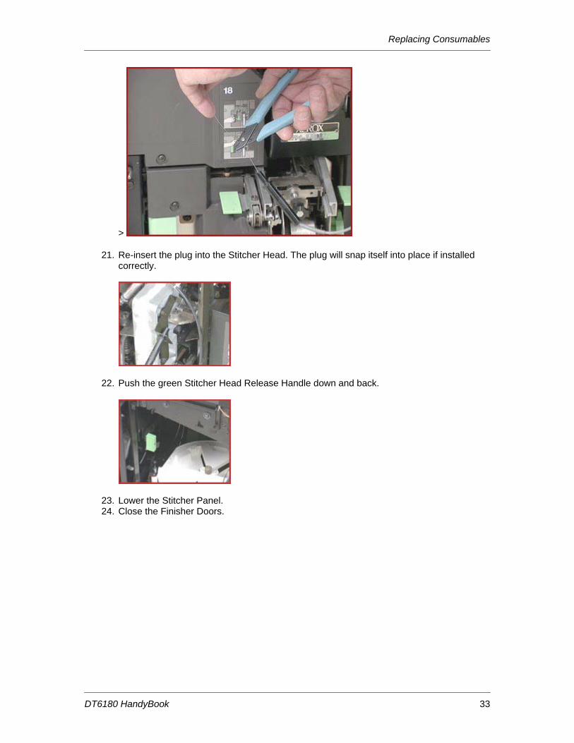
21. Re-insert the plug into the Stitcher Head. The plug will snap itself into place if installed correctly.
22. Push the green Stitcher Head Release Handle down and back.
23. Lower the Stitcher Panel. 24. Close the Finisher Doors.
Replacing Consumables
DT6180 HandyBook 34
Replace the Binder Tape Reel
1. Open the Finisher Doors.
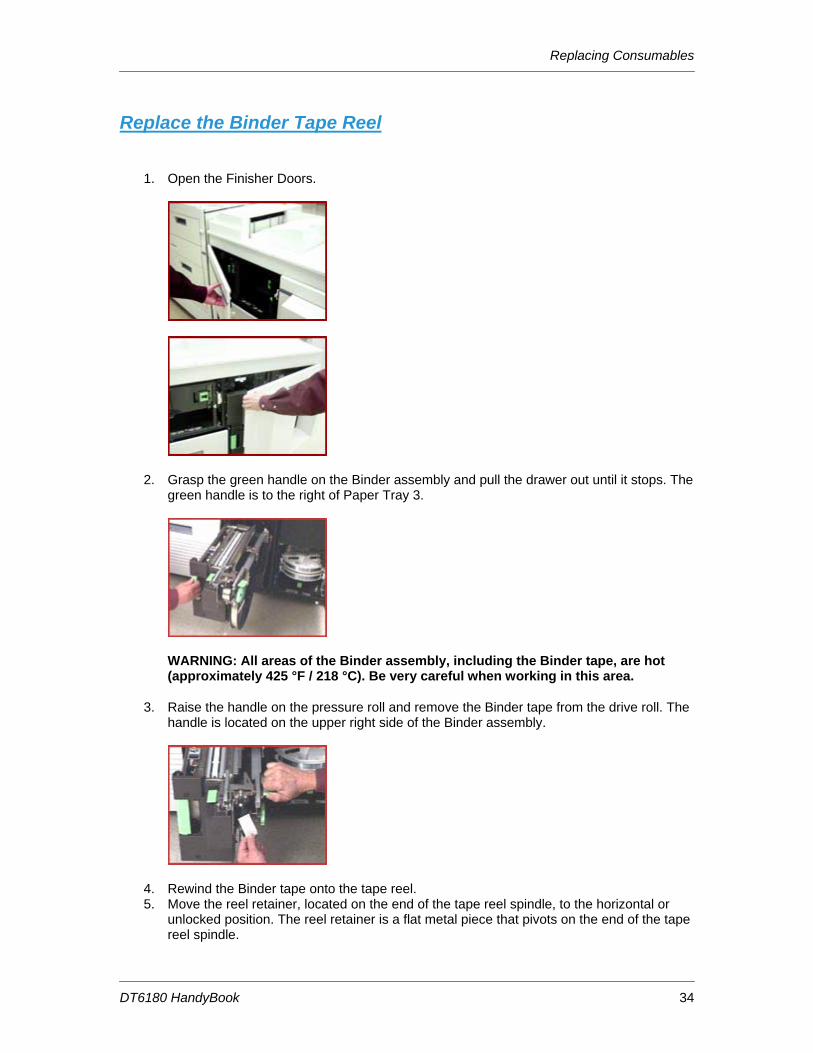
2. Grasp the green handle on the Binder assembly and pull the drawer out until it stops. The green handle is to the right of Paper Tray 3.
WARNING: All areas of the Binder assembly, including the Binder tape, are hot (approximately 425 °F / 218 °C). Be very careful when working in this area.
3. Raise the handle on the pressure roll and remove the Binder tape from the drive roll. The handle is located on the upper right side of the Binder assembly.
4. Rewind the Binder tape onto the tape reel. 5. Move the reel retainer, located on the end of the tape reel spindle, to the horizontal or
unlocked position. The reel retainer is a flat metal piece that pivots on the end of the tape reel spindle.
Replacing Consumables
DT6180 HandyBook 35
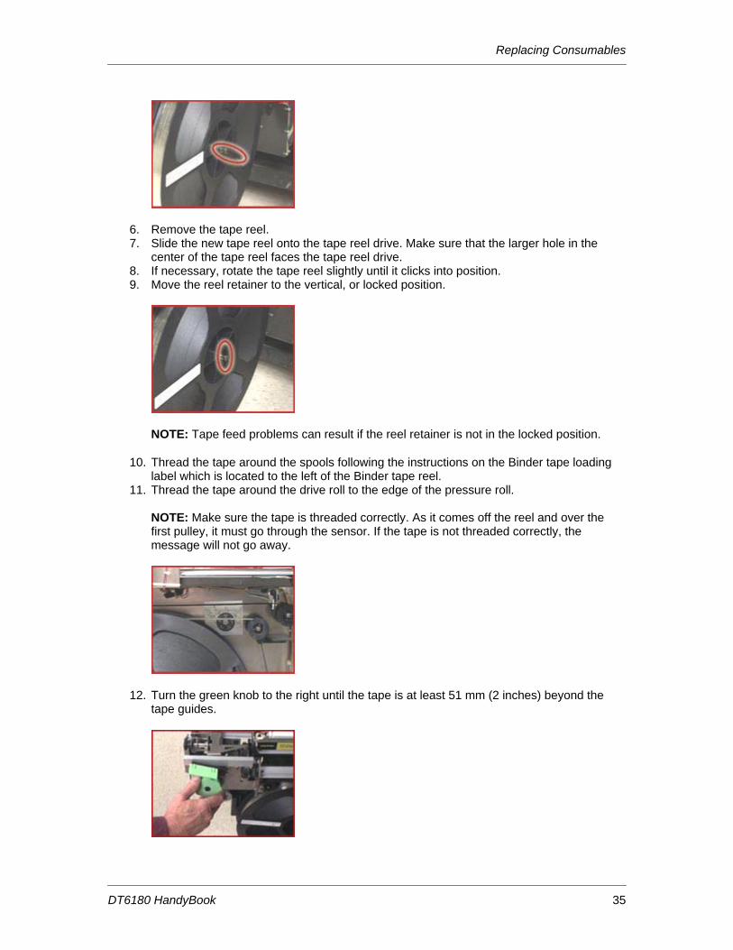
6. Remove the tape reel. 7. Slide the new tape reel onto the tape reel drive. Make sure that the larger hole in the
center of the tape reel faces the tape reel drive. 8. If necessary, rotate the tape reel slightly until it clicks into position. 9. Move the reel retainer to the vertical, or locked position.
NOTE: Tape feed problems can result if the reel retainer is not in the locked position.
10. Thread the tape around the spools following the instructions on the Binder tape loading label which is located to the left of the Binder tape reel.
11. Thread the tape around the drive roll to the edge of the pressure roll. NOTE: Make sure the tape is threaded correctly. As it comes off the reel and over the first pulley, it must go through the sensor. If the tape is not threaded correctly, the message will not go away.
12. Turn the green knob to the right until the tape is at least 51 mm (2 inches) beyond the tape guides.
Replacing Consumables
DT6180 HandyBook 36
NOTE: If a problem occurs when you are trying to turn the green knob, close the Finisher Doors. The Screen will display a 'Please wait - Finisher Reset in Progress' message. Wait until a 'Ready' message is displayed, then open the Finisher Doors and try feeding the Binder tape again.
13. Cut the tape by lifting up on the green tape cutter handle located on the left side of the Binder assembly. Lift up the handle to manually cut the tape and then release the handle.
14. Remove the cut piece of tape.
15. Push the Binder drawer in until it stops. 16. Close the Finisher Doors.
For the highest quality performance, occasionally check the Binder tape length and adjust, if necessary.
Replacing Consumables
DT6180 HandyBook 37
Replace the Toner (Dry Ink) Bottle CAUTION: Do not use warm water or cleaning solvents to remove Toner from your skin or clothing. This will set the Toner and make it difficult to remove. If Toner gets on your skin or clothing, use a brush to remove the Toner, blow it off, or wash it off with cold water and mild soap. NOTE: There is an eight step diagram to the right of the Toner Bottle with instructions on how to change the cartridge. To remove the Toner (Dry Ink) Bottle:
1. Open the Processor Doors. 2. Place a drop cloth or a few sheets of paper on the floor under the Toner Bottle area to
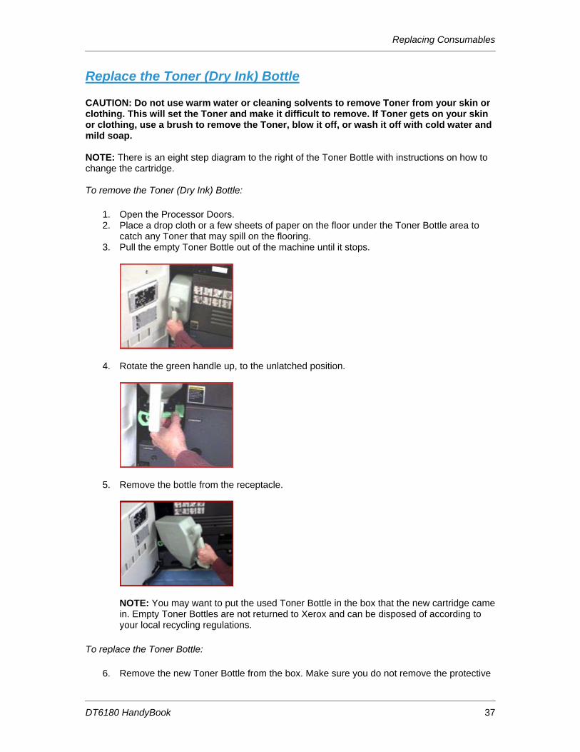
catch any Toner that may spill on the flooring. 3. Pull the empty Toner Bottle out of the machine until it stops.
4. Rotate the green handle up, to the unlatched position.
5. Remove the bottle from the receptacle.
NOTE: You may want to put the used Toner Bottle in the box that the new cartridge came in. Empty Toner Bottles are not returned to Xerox and can be disposed of according to your local recycling regulations.
To replace the Toner Bottle:
6. Remove the new Toner Bottle from the box. Make sure you do not remove the protective
Replacing Consumables
DT6180 HandyBook 38
seal that is attached to the bottle. 7. Shake the new bottle several times to loosen the Toner. 8. Insert the bottle into the receptacle. 9. Rotate the green handle down, to the latched position.
10. Push the new bottle all the way into the machine. 11. Hold the bottle in place with your hand and pull off the protective seal.
12. Close the Processor Doors.
Replace the Toner (Dry Ink) Waste Container NOTE: When the message 'Replace the Waste Container' is displayed on your machine, replace the container as soon as possible. If the Toner (Dry Ink) Waste Container is not replaced, the machine will eventually stop and will not run until the container is replaced. To replace the Toner Waste Container:
1. Open the Processor Doors. 2. Locate the Toner Waste Container which is located directly under Area 6, near the floor. 3. Place a drop cloth or a few sheets of paper on the floor under the Toner Waste Container
area to catch any Toner that may spill. 4. Grasp the tab on the Toner Waste Container and pull the container out of the machine,
slowly.
Replacing Consumables
DT6180 HandyBook 39
CAUTION: To prevent a Toner spill, do not tip or tilt the waste container.
5. Remove the cap from the top of the full Toner Waste Container.
6. Place the cap over the opening on the end of the full Toner Waste Container.
7. Remove the new Toner Waste Container from the box. 8. Slide the new Toner Waste Container all the way into the machine until the container
stops. NOTE: You do not need to remove the cap from the storage position at this time.
9. Close the Processor Doors.
CAUTION: Do not use warm water or cleaning solvents to remove Toner from your skin or clothing. This will set the Toner and make it difficult to remove. If any Toner gets on your skin or clothing, use a brush to remove the Toner, blow it off, or wash it off with cold water and mild soap. NOTE: Old waste containers should not be emptied, cleaned and used again. There is a sensor inside the container that remains dirty and the machine will not recognize the container. Save the full waste container and give it to the service technician on the next visit. The technician will dispose of it properly. This material is not a hazardous waste.
Replacing Consumables
DT6180 HandyBook 40
Order Supplies, Consumables, and Parts DT135/6100/6115/6135/6155/6180 Supplies/Consumables/Parts
EQUIPMENT SUPPLIES
Dry Ink Waste Container - 502S67618 Please call the Parts Desk 1-800-828-5881
To order supplies (toner, fuser oil, staples, paper, transparencies, labels, etc), please call the Xerox Supplies Department or order online.
1-800-822-2200 http://www.xerox.com
RECYCLING
You can return CRU's to Xerox by using the return shipping labels which are included in the packing materials. Or you can order replacement online.
http://www.xerox.com/gwa
METERED SUPPLIES (Auto-Replenish) If you are a metered account, please call the Metered Account Hotline. 1-800-599-2198
SOLD TIME AND MATERIALS (No Contract) If you do not have a maintenance agreement and need to order CRU's, please call the T&M Parts Desk. 1-800-828-5881
Machine Maintenance
DT6180 HandyBook 41
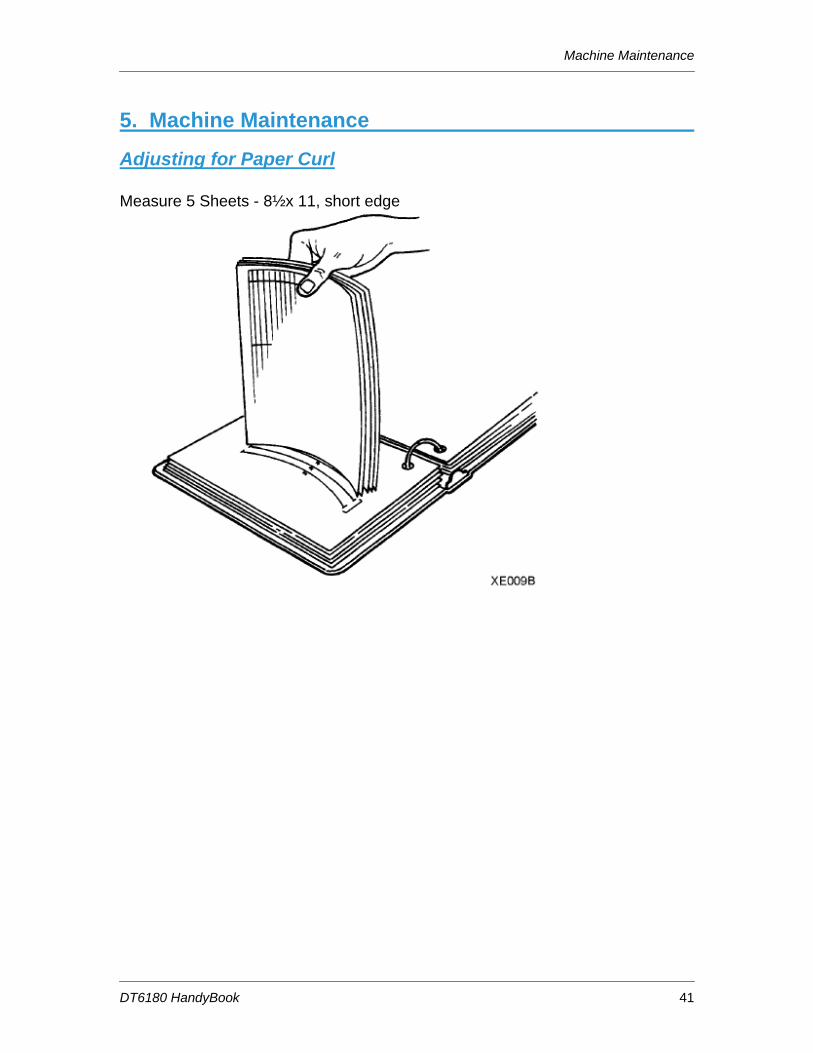
5. Machine Maintenance
Adjusting for Paper Curl Measure 5 Sheets - 8½x 11, short edge
Machine Maintenance
DT6180 HandyBook 42
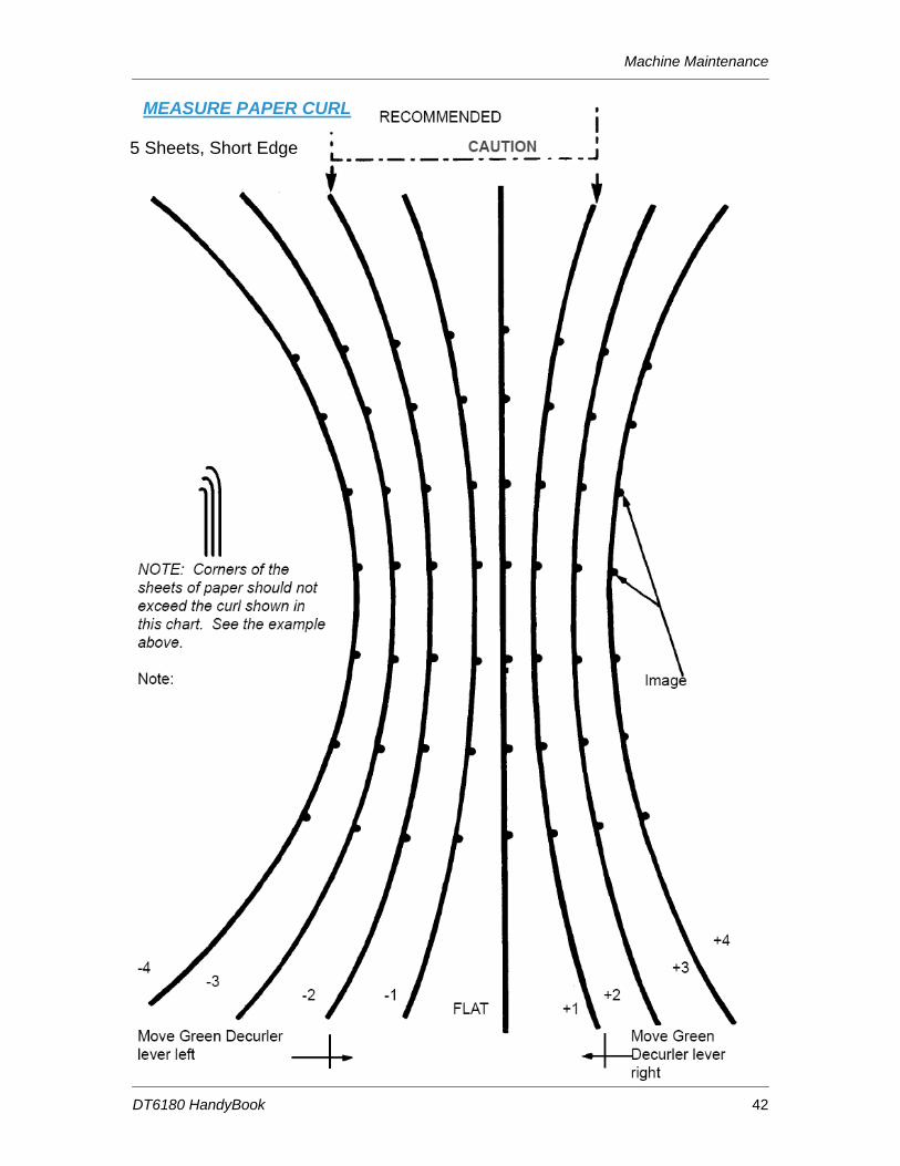
5 Sheets, Short Edge
MEASURE PAPER CURL
Machine Maintenance
DT6180 HandyBook 43
Adjusting for Paper Curl - Adjusting the Decurler Lever
1. Open the right door of the processor. 2. Locate the decurler lever in area 7 of the paper path, as shown below.
3. If the print curl is +2 or more, move the green decurler lever to the right. 4. If the print curl is -3 or more, move the green decurler lever to the left. 5. If the decurler adjustment does not eliminate the paper curl problem, or for other curl
problems, turn the stack of paper over in the paper tray. 6. If there is still a curl problem, perform steps 1 to 4 again.
NOTE: A final solution to the curl problem may be to load a new ream of paper. 7. Close the processor door.
Machine Maintenance
DT6180 HandyBook 44
Adjusting the Heavy Paper Levers Adjust the heavy paper levers to prevent skewing from heavy weight or long paper.
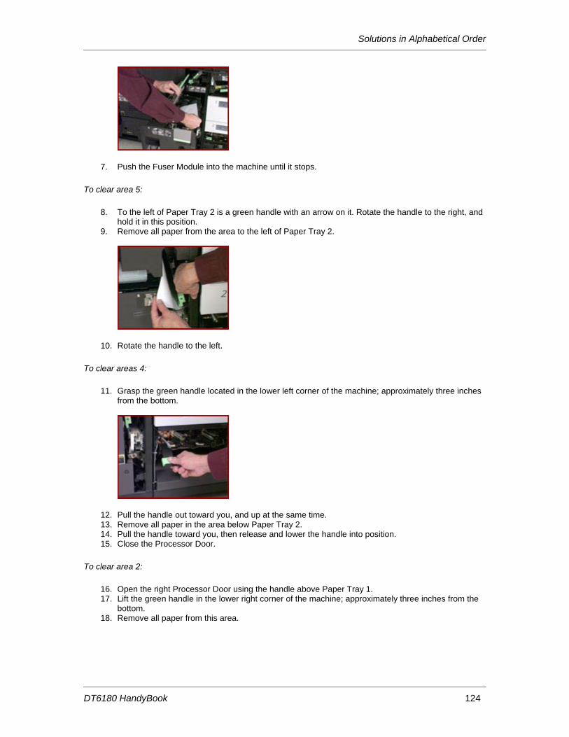
1. Open the right door of the processor. 2. Open the left door of the processor. 3. Locate the black heavy paper levers behind area 4 and area 2. 4. Raise the heavy paper levers.
a. Pull the silver latch release toward you. b. Raise the left and right black levers to the vertical position, as shown below.
Raising the levers
Machine Maintenance
DT6180 HandyBook 45
5. Run the print job. 6. When the print job has been completed, lower the heavy paper lever.
a. Pull the silver latch release toward you. b. Lower the left and right black levers to the horizontal position, as shown below.
Lowering the levers
8. Close the processor door
Machine Maintenance
DT6180 HandyBook 46
Adjust the Binder Tape Registration NOTE: Adjusting the top edge of the Binder Tape changes the positioning of the tape. Adjusting the bottom of the Binder Tape changes the length of the tape. To adjust the Binder Tape registration:
1. Make sure that the tape guides are clean and free of glue residue. The tape guides are on the top of the Binder.
2. Measure the adjustment amount for the top edge of a finished book. If the tape is overhanging on the top or bottom, and not covering the bottom or top, then the tape position needs to be adjusted.
3. Open the Finisher Doors.
4. Locate the black Binder tape knob on the front of the Binder Drawer; just to the right of Paper Tray 3. You should see the Binder tape coming out from the bottom and wrapping around the feeder back into the Finisher.
The knob is spring loaded and moves in increments to change the location of the Binder tape. Each increment equals a change of 0.1 mm, up or down, on the edge of the book. One full rotation of the knob is equal to 1 mm (0.04 inch).
5. Pull the knob toward you to rotate it for the adjustment. 6. Adjust the tape position by performing one of the following steps:
• Pull the knob and rotate it to the right to move the tape toward the top edge of the book, or
• Pull the knob and rotate it the left to move the tape toward the bottom edge of the
Machine Maintenance
DT6180 HandyBook 47
book. 7. Close the Finisher Doors. 8. Run a test job to inspect your adjustment. 9. If necessary, perform the procedure again as needed.
Enable a Paper Tray for Clean up If you are using DocuSP software version 3.x and above:
1. From the DocuSP for DocuTech 2000 Series for 61xx window, select [Printer Manager]. The Printer Manager window will be displayed.
2. Right-click on the tray and select [Enable Cleanup] from the menu. A broom, in the fourth column from the left-hand side of the window, will mark the tray for clean up.
3. Repeat these steps until all trays you want enabled for clean up have a broom in column. 4. Select [Resume] in the Printer window.
If you are using DocuSP software version 2.x and below:
1. From the DocuSP Print Services window, select [Printer Manager]. The Printer Manager window will be displayed.
2. Select the tray you wish to enable for clean up. A menu will be displayed. 3. Select [Enable Clean Up] from the menu. 4. Repeat these steps until all trays you want enabled have a green check mark in the
Clean Up column. 5. Select [Resume] in Printer window.
Enable or Disable the Binder NOTE: You will need to logon as a System Administrator to perform this task. To enable the Binder using DocuTech software version 3.x and above:
1. From the DocuSP for DocuTech 2000 Series for 61xx window, select [Printer Manager]. The Printer Manager window will be displayed.
2. Select the [Finishing] tab. 3. Under Internal Finishers, right-click on [Binder]. A menu will be displayed. 4. Select [Enable] or [Disable] from the menu. The status column will display the selection.
To enable the Binder using DocuTech software version 2.x and below: 1. From the DocuSP Print Services window, select [Printer Manager]. The Print Manager
window will be displayed. 2. In Printer Manager, select [Options]. A menu will be displayed. 3. Select [Finishing] from the menu. The Finishing window will be displayed. 4. Select the [On-line Finishers] tab. 5. Select [Binder]. 6. Select the Binder check box to disable or enable the Binder. A check mark in the box
indicates the Binder is enabled. 7. Select [OK] to return to the Print Manager window.
Machine Maintenance
DT6180 HandyBook 48
Enable or Disable the Stacker NOTE: Before you begin, you must be logged on as a System Administrator or Trusted User. To enable or disable the Stacker using DocuSP software version 3.x:
1. Select [Printer Manager] on the DocuSP for DocuTech 2000 Series for 61xx window. 2. Select the [Stacking] tab. 3. Right-click on [Stacker] and select [Enable] or [Disable]. The Status column should now
display the changed setting.
To enable or disable the Stacker using DocuSP software version 2.x or below:
1. Select [Printer Manager]. The Printer Manager window will be displayed. 2. Select [Options] on the toolbar. A menu will be displayed. 3. Select [Finishing] from the menu. 4. On the Finishing tab, select the [Stacker] box. A check mark will be displayed if the
Stacker is enabled. Make sure there is no check mark inside the box if you want the Stacker disabled.
5. Select [Apply]. 6. Select [Close].
Enable or Disable the Stitcher NOTE: Before you begin you must be logged on as a System Administrator or Trusted User. To enable or disable the Stitcher using DocuSP software version 3.x:
1. From the DocuSP for DocuTech 2000 Series 61xx window, select [Printer Manager]. The Print Manager window will be displayed.
2. Select the [Finishing] tab. 3. Under Internal Finishers, right-click on [Stitcher]. A menu will be displayed. 4. Select [Enable] or [Disable] from the menu. The status column should now display the
changed setting.
To enable or disable the Stitcher using DocuSP software version 2.x or below:
1. From the DocuSP Print Services window, select [Printer Manager]. The Print Manager window will be displayed.
2. Select [Options] on the toolbar. A menu will be displayed. 3. Select [Finishing] from the menu. The Finishing window will be displayed. 4. On the Finishing tab, select the [Stitcher]. A green check mark will be displayed in the
box if the Stitcher is enabled. Make sure the green check mark is not displayed to disable the Stitcher.
5. Select [Apply]. 6. Select [Close].
Machine Maintenance
DT6180 HandyBook 49
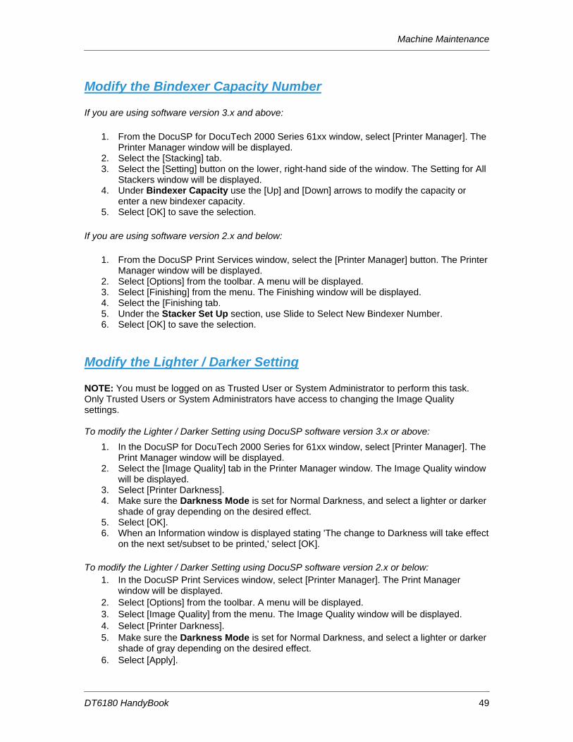
Modify the Bindexer Capacity Number If you are using software version 3.x and above:
1. From the DocuSP for DocuTech 2000 Series 61xx window, select [Printer Manager]. The Printer Manager window will be displayed.
2. Select the [Stacking] tab. 3. Select the [Setting] button on the lower, right-hand side of the window. The Setting for All
Stackers window will be displayed. 4. Under Bindexer Capacity use the [Up] and [Down] arrows to modify the capacity or
enter a new bindexer capacity. 5. Select [OK] to save the selection.
If you are using software version 2.x and below:
1. From the DocuSP Print Services window, select the [Printer Manager] button. The Printer Manager window will be displayed.
2. Select [Options] from the toolbar. A menu will be displayed. 3. Select [Finishing] from the menu. The Finishing window will be displayed. 4. Select the [Finishing tab. 5. Under the Stacker Set Up section, use Slide to Select New Bindexer Number. 6. Select [OK] to save the selection.
Modify the Lighter / Darker Setting NOTE: You must be logged on as Trusted User or System Administrator to perform this task. Only Trusted Users or System Administrators have access to changing the Image Quality settings. To modify the Lighter / Darker Setting using DocuSP software version 3.x or above:
1. In the DocuSP for DocuTech 2000 Series for 61xx window, select [Printer Manager]. The Print Manager window will be displayed.
2. Select the [Image Quality] tab in the Printer Manager window. The Image Quality window will be displayed.
3. Select [Printer Darkness]. 4. Make sure the Darkness Mode is set for Normal Darkness, and select a lighter or darker
shade of gray depending on the desired effect. 5. Select [OK]. 6. When an Information window is displayed stating 'The change to Darkness will take effect
on the next set/subset to be printed,' select [OK].
To modify the Lighter / Darker Setting using DocuSP software version 2.x or below: 1. In the DocuSP Print Services window, select [Printer Manager]. The Print Manager
window will be displayed. 2. Select [Options] from the toolbar. A menu will be displayed. 3. Select [Image Quality] from the menu. The Image Quality window will be displayed. 4. Select [Printer Darkness]. 5. Make sure the Darkness Mode is set for Normal Darkness, and select a lighter or darker
shade of gray depending on the desired effect. 6. Select [Apply].
Machine Maintenance
DT6180 HandyBook 50
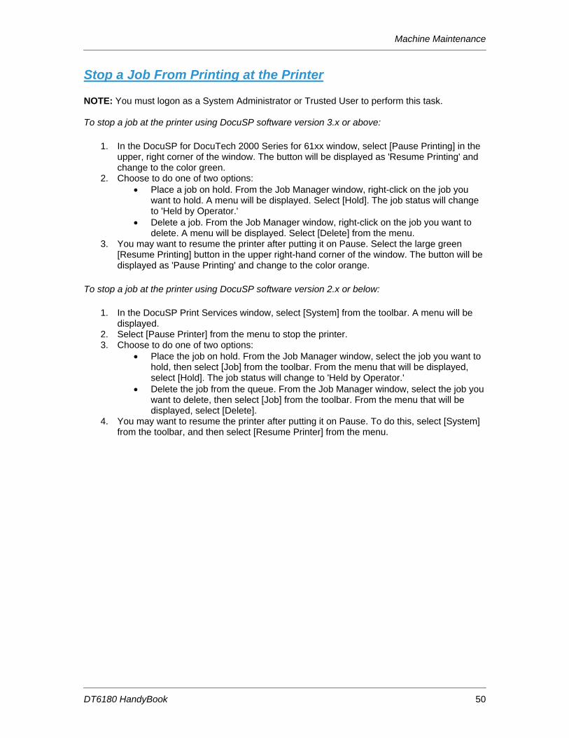
Stop a Job From Printing at the Printer NOTE: You must logon as a System Administrator or Trusted User to perform this task. To stop a job at the printer using DocuSP software version 3.x or above:
1. In the DocuSP for DocuTech 2000 Series for 61xx window, select [Pause Printing] in the upper, right corner of the window. The button will be displayed as 'Resume Printing' and change to the color green.
2. Choose to do one of two options: • Place a job on hold. From the Job Manager window, right-click on the job you
want to hold. A menu will be displayed. Select [Hold]. The job status will change to 'Held by Operator.'
• Delete a job. From the Job Manager window, right-click on the job you want to delete. A menu will be displayed. Select [Delete] from the menu.
3. You may want to resume the printer after putting it on Pause. Select the large green [Resume Printing] button in the upper right-hand corner of the window. The button will be displayed as 'Pause Printing' and change to the color orange.
To stop a job at the printer using DocuSP software version 2.x or below:
1. In the DocuSP Print Services window, select [System] from the toolbar. A menu will be displayed.
2. Select [Pause Printer] from the menu to stop the printer. 3. Choose to do one of two options:
• Place the job on hold. From the Job Manager window, select the job you want to hold, then select [Job] from the toolbar. From the menu that will be displayed, select [Hold]. The job status will change to 'Held by Operator.'
• Delete the job from the queue. From the Job Manager window, select the job you want to delete, then select [Job] from the toolbar. From the menu that will be displayed, select [Delete].
4. You may want to resume the printer after putting it on Pause. To do this, select [System] from the toolbar, and then select [Resume Printer] from the menu.
Problem Solving
DT6180 HandyBook 51
6. Problem Solving Potential solutions for common problems are available using the either of 2 methods:
1. If you know the fault code:
A. Look up Fault Code in the table, “COMMON FAULT CODES & CASE”, find Case Number (page 50 - page 52).
B. Look up Case Number in the table, “PROBLEM LISTING AND SOLUTIONS, LISTED by CASE NUMBER” to find Solution(s) (page 53 – page 63).
C. Potential Solutions are listed by relevance.
D. Potential Solutions with detailed instructions are noted in last column. The instructions are listed in alphabetical order starting on page 66.
2. If you have a problem without a fault code:
A. Refer to pages (page 53 – page 63) in Problem Listing Table, look for Problem Description.
B. Potential Solutions are listed by relevance.
C. Potential Solutions with detailed instructions are noted in last column. The instructions are listed in alphabetical order starting on page 66.
Problem Solving
DT6180 HandyBook 52
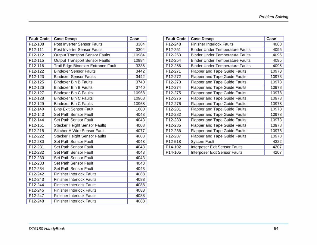
COMMON FAULT CODES & CASE Look-up Case Number in table “PROBLEM LISTING AND SOLUTIONS, LISTED by CASE NUMBER”, following Fault code table, for solutions. Fault Code Case Descp Case C16-351 Communication Failure Faults 10971C16-352 Communication Failure Faults 10971P01-220 Interlock System Failure Faults 3147P01-221 Interlock System Failure Faults 3147P03-201 Printer Run Faults 2823P03-203 Printer Run Faults 2823P03-204 Printer Run Faults 2823P03-205 Printer Run Faults 2823P03-208 Printer Run Faults 2823P03-230 Printer Run Faults 2823P03-230 Printer Run Faults 2823P03-231 Printer Run Faults 2823P03-232 Printer Run Faults 2823P03-233 Printer Run Faults 2823P03-234 Printer Run Faults 2823P03-240 Printer Run Faults 2823P03-241 Printer Run Faults 2823P03-242 Printer Run Faults 2823P03-243 Printer Run Faults 2823P03-246 Printer Run Faults 2823P03-247 Printer Run Faults 2823P03-250 Printer Run Faults 2823P03-251 Printer Run Faults 2823P03-252 Printer Run Faults 2823P03-252 Printer Run Faults 2823
Fault Code Case Descp Case P03-253 Printer Run Faults 2823P03-254 Printer Run Faults 2823P03-255 Printer Run Faults 2823P03-258 Printer Run Faults 2823P03-259 Printer Run Faults 2823P03-261 Printer Run Faults 2823P03-263 Printer Run Faults 2823P03-300 Printer Run Faults 2823P03-301 Printer Run Faults 2823P03-302 Printer Run Faults 2823P03-308 Printer Run Faults 2823P03-309 Printer Run Faults 2823P03-311 Printer Run Faults 2823P03-313 Printer Run Faults 2823P03-313 Printer Run Faults 2823P03-314 Printer Run Faults 2823P03-315 Printer Run Faults 2823P03-325 Printer Run Faults 2823P03-330 Printer Run Faults 2823P03-331 Printer Run Faults 2823P03-332 Printer Run Faults 2823P03-333 Printer Run Faults 2823P03-334 Printer Run Faults 2823P03-336 Printer Run Faults 2823P03-342 Printer Run Faults 2823P03-343 Printer Run Faults 2823P03-344 Printer Run Faults 2823P03-361 Printer Run Faults 2823P03-361 Printer Run Faults 2823P03-363 Printer Run Faults 2823
Problem Solving
DT6180 HandyBook 53
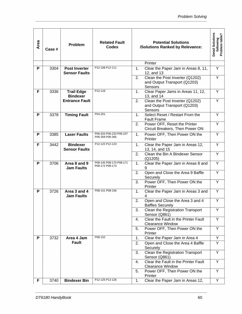
Fault Code Case Descp Case P03-364 Printer Run Faults 2823P03-370 Printer Run Faults 2823P03-371 Printer Run Faults 2823P03-373 Printer Run Faults 2823P03-374 Printer Run Faults 2823P03-375 Printer Run Faults 2823P03-378 Printer Run Faults 2823P04-201 Timing Fault 3378P06-203 Laser Faults 3385P06-233 Laser Faults 3385P06-237 Laser Faults 3385P06-359 Laser Faults 3385P06-365 Laser Faults 3385P08-145 Area 8 and 9 Jam Faults 3706P08-151 Area 3 and 4 Jam Faults 3726P08-152 Area 4 Jam Fault 3732P08-156 Area 3 and 4 Jam Faults 3726P08-170 Area 8 and 9 Jam Faults 3706P08-171 Area 8 and 9 Jam Faults 3706P08-172 Area 8 and 9 Jam Faults 3706P08-173 Area 8 and 9 Jam Faults 3706P09-201 Arc Detection Faults 3792P09-202 Arc Detection Faults 3792P09-203 PR Belt End of Life Message 10987P09-204 PR Belt End of Life Message 10987P09-213 ESV Fault 3803P09-215 Toner (Dry Ink) Dispense Fault 3806P09-220 Belt Hole Sensor Faults 3811P09-222 Belt Hole Sensor Faults 3811P09-320 Processor Voltage Faults 3831
Fault Code Case Descp Case P09-321 Processor Voltage Faults 3831P09-322 Processor Voltage Faults 3831P09-323 Processor Voltage Faults 3831P09-324 Processor Voltage Faults 3831P09-325 Processor Voltage Faults 3831P09-325 Processor Voltage Faults 3831P09-326 Processor Voltage Faults 3831P09-327 Processor Voltage Faults 3831P09-328 Processor Voltage Faults 3831P09-329 Processor Voltage Faults 3831P09-331 Processor Voltage Faults 3831P09-504 ESV Fault 3803P10-101 Pre-Fuser Sensor Fault 3847P10-102 Fuser Jam Sensor Fault 2843P10-104 Decurler Sensor Fault 3142P10-105 Decurler Sensor Fault 3142P10-201 Fuser Temperature Faults 3853P10-202 Fuser Temperature Faults 3853P10-203 Fuser Temperature Faults 3853P10-204 Fuser Temperature Faults 3853P10-206 Fuser Temperature Faults 3853P10-210 Fuser Temperature Faults 3853P10-215 Fuser Temperature Faults 3853P10-215 Fuser Temperature Faults 3853P10-216 Camming Fault 2549P12-100 Finisher Entrance Faults 3265P12-101 Finisher Entrance Sensor Blocked
Faults 3273
P12-104 Finisher Entrance Sensor Blocked Faults
3273
P12-107 Finisher Entrance Faults 3265
Problem Solving
DT6180 HandyBook 54
Fault Code Case Descp Case P12-108 Post Inverter Sensor Faults 3304P12-111 Post Inverter Sensor Faults 3304P12-112 Output Transport Sensor Faults 10984P12-115 Output Transport Sensor Faults 10984P12-116 Trail Edge Bindexer Entrance Fault 3336P12-122 Bindexer Sensor Faults 3442P12-123 Bindexer Sensor Faults 3442P12-125 Bindexer Bin B Faults 3740P12-126 Bindexer Bin B Faults 3740P12-127 Bindexer Bin C Faults 10968P12-128 Bindexer Bin C Faults 10968P12-129 Bindexer Bin C Faults 10968P12-140 Bins Exit Sensor Fault 1680P12-143 Set Path Sensor Fault 4043P12-144 Set Path Sensor Fault 4043P12-151 Stacker Height Sensor Faults 4003P12-218 Stitcher A Wire Sensor Fault 4077P12-222 Stacker Height Sensor Faults 4003P12-230 Set Path Sensor Fault 4043P12-231 Set Path Sensor Fault 4043P12-232 Set Path Sensor Fault 4043P12-233 Set Path Sensor Fault 4043P12-233 Set Path Sensor Fault 4043P12-234 Set Path Sensor Fault 4043P12-242 Finisher Interlock Faults 4088P12-243 Finisher Interlock Faults 4088P12-244 Finisher Interlock Faults 4088P12-245 Finisher Interlock Faults 4088P12-247 Finisher Interlock Faults 4088P12-248 Finisher Interlock Faults 4088
Fault Code Case Descp Case P12-248 Finisher Interlock Faults 4088P12-251 Binder Under Temperature Faults 4095P12-253 Binder Under Temperature Faults 4095P12-254 Binder Under Temperature Faults 4095P12-256 Binder Under Temperature Faults 4095P12-271 Flapper and Tape Guide Faults 10978P12-272 Flapper and Tape Guide Faults 10978P12-273 Flapper and Tape Guide Faults 10978P12-274 Flapper and Tape Guide Faults 10978P12-275 Flapper and Tape Guide Faults 10978P12-276 Flapper and Tape Guide Faults 10978P12-276 Flapper and Tape Guide Faults 10978P12-281 Flapper and Tape Guide Faults 10978P12-282 Flapper and Tape Guide Faults 10978P12-283 Flapper and Tape Guide Faults 10978P12-285 Flapper and Tape Guide Faults 10978P12-286 Flapper and Tape Guide Faults 10978P12-287 Flapper and Tape Guide Faults 10978P12-518 System Fault 4322P14-102 Interposer Exit Sensor Faults 4207P14-105 Interposer Exit Sensor Faults 4207
Problem Solving
DT6180 HandyBook 55
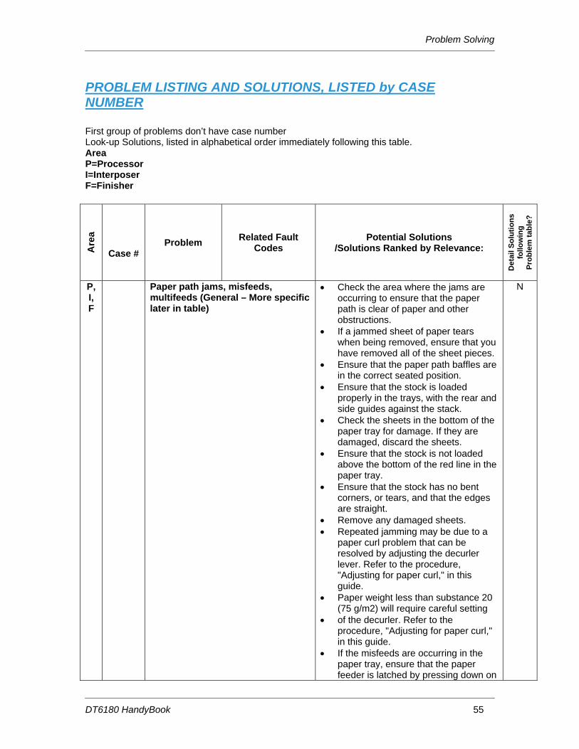
PROBLEM LISTING AND SOLUTIONS, LISTED by CASE NUMBER
First group of problems don’t have case number Look-up Solutions, listed in alphabetical order immediately following this table. Area P=Processor I=Interposer F=Finisher
Are
a
Case # Problem Related Fault
Codes Potential Solutions
/Solutions Ranked by Relevance:
Det
ail S
olut
ions
fo
llow
ing
Prob
lem
tabl
e?
P, I, F
Paper path jams, misfeeds, multifeeds (General – More specific later in table)
• Check the area where the jams are occurring to ensure that the paper path is clear of paper and other obstructions.
• If a jammed sheet of paper tears when being removed, ensure that you have removed all of the sheet pieces.
• Ensure that the paper path baffles are in the correct seated position.
• Ensure that the stock is loaded properly in the trays, with the rear and side guides against the stack.
• Check the sheets in the bottom of the paper tray for damage. If they are damaged, discard the sheets.
• Ensure that the stock is not loaded above the bottom of the red line in the paper tray.
• Ensure that the stock has no bent corners, or tears, and that the edges are straight.
• Remove any damaged sheets. • Repeated jamming may be due to a
paper curl problem that can be resolved by adjusting the decurler lever. Refer to the procedure, "Adjusting for paper curl," in this guide.
• Paper weight less than substance 20 (75 g/m2) will require careful setting
• of the decurler. Refer to the procedure, "Adjusting for paper curl," in this guide.
• If the misfeeds are occurring in the paper tray, ensure that the paper feeder is latched by pressing down on
N
Problem Solving
DT6180 HandyBook 56
Are
a
Case # Problem Related Fault
Codes Potential Solutions
/Solutions Ranked by Relevance:
Det
ail S
olut
ions
fo
llow
ing
Prob
lem
tabl
e?
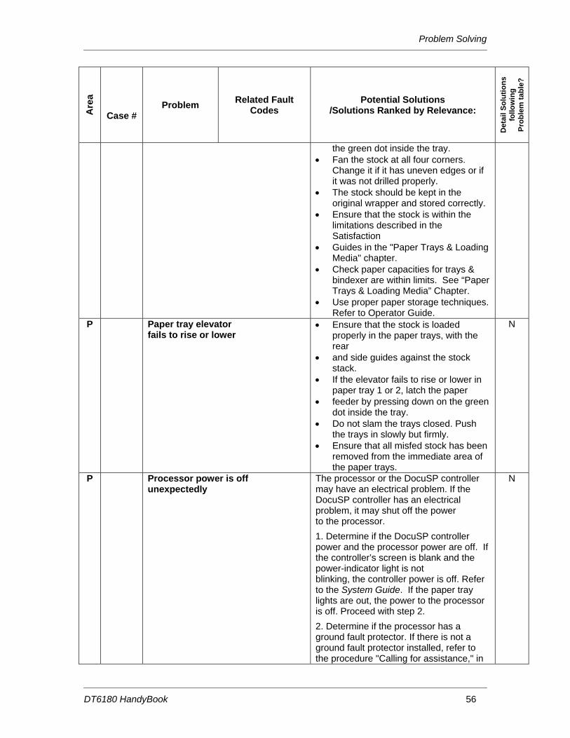
the green dot inside the tray. • Fan the stock at all four corners.
Change it if it has uneven edges or if it was not drilled properly.
• The stock should be kept in the original wrapper and stored correctly.
• Ensure that the stock is within the limitations described in the Satisfaction
• Guides in the "Paper Trays & Loading Media" chapter.
• Check paper capacities for trays & bindexer are within limits. See “Paper Trays & Loading Media” Chapter.
• Use proper paper storage techniques. Refer to Operator Guide.
P Paper tray elevator fails to rise or lower
• Ensure that the stock is loaded properly in the paper trays, with the rear
• and side guides against the stock stack.
• If the elevator fails to rise or lower in paper tray 1 or 2, latch the paper
• feeder by pressing down on the green dot inside the tray.
• Do not slam the trays closed. Push the trays in slowly but firmly.
• Ensure that all misfed stock has been removed from the immediate area of the paper trays.
N
P Processor power is off unexpectedly
The processor or the DocuSP controller may have an electrical problem. If the DocuSP controller has an electrical problem, it may shut off the power to the processor.
1. Determine if the DocuSP controller power and the processor power are off. If the controller’s screen is blank and the power-indicator light is not blinking, the controller power is off. Refer to the System Guide. If the paper tray lights are out, the power to the processor is off. Proceed with step 2.
2. Determine if the processor has a ground fault protector. If there is not a ground fault protector installed, refer to the procedure "Calling for assistance," in
N
Problem Solving
DT6180 HandyBook 57
Are
a
Case # Problem Related Fault
Codes Potential Solutions
/Solutions Ranked by Relevance:
Det
ail S
olut
ions
fo
llow
ing
Prob
lem
tabl
e?
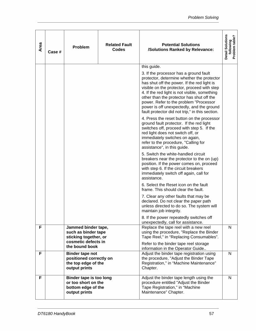
this guide.
3. If the processor has a ground fault protector, determine whether the protector has shut off the power. If the red light is visible on the protector, proceed with step 4. If the red light is not visible, something other than the protector has shut off the power. Refer to the problem "Processor power is off unexpectedly, and the ground fault protector did not trip," in this section.
4. Press the reset button on the processor ground fault protector. If the red light switches off, proceed with step 5. If the red light does not switch off, or immediately switches on again, refer to the procedure, "Calling for assistance", in this guide.
5. Switch the white-handled circuit breakers near the protector to the on (up) position. If the power comes on, proceed with step 6. If the circuit breakers immediately switch off again, call for assistance.
6. Select the Reset icon on the fault frame. This should clear the fault.
7. Clear any other faults that may be declared. Do not clear the paper path unless directed to do so. The system will maintain job integrity.
8. If the power repeatedly switches off unexpectedly, call for assistance.
F Jammed binder tape, such as binder tape sticking together, or cosmetic defects in the bound book
Replace the tape reel with a new reel using the procedure, "Replace the Binder Tape Reel," in “Replacing Consumables”.
Refer to the binder tape reel storage information in the Operator Guide..
N
F Binder tape not positioned correctly on the top edge of the output prints
Adjust the binder tape registration using the procedure, "Adjust the Binder Tape Registration," in “Machine Maintenance” Chapter.
N
F Binder tape is too long or too short on the bottom edge of the output prints
Adjust the binder tape length using the procedure entitled "Adjust the Binder Tape Registration," in “Machine Maintenance” Chapter.
N
Problem Solving
DT6180 HandyBook 58
Are
a
Case # Problem Related Fault
Codes Potential Solutions
/Solutions Ranked by Relevance:
Det
ail S
olut
ions
fo
llow
ing
Prob
lem
tabl
e?
If an adjustment is made to the binder tape length during a job, it will not take effect until the next job is printed. If it is necessary to adjust the binder tape length during a job, adjust it using the procedures in the on-line help.
F Loose binder tape along the spine of the completed bound book
This is a symptom of excessive moisture in the tape. Replace the tape reel with a new reel using the procedure, "Replace the Binder Tape Reel," in “Replacing Consumables”.
Refer to the binder tape storage guidelines in the Operator Guide.
N
F Repeated tape feeding problems, such as binder tape not unwinding from the reel
If the binder tape is sticking together, or if there are cosmetic defects in the bound book, replace the tape reel with a new reel using the procedure, "Replace the Binder Tape Reel," in “Replacing Consumables”.
Refer to the binder tape storage information in the Operator Guide.
Refer to the binder cleaning information in the Operator Guide.
N
F Poor stitch quality or short stitches
Reliable stitching can be expected with up to 65 sheets of substance 20 (75 g/m2) or 0.28 inch (7 mm) thick sets. Less reliable stitching can be expected with over 70 sheets of substance 20 (75 g/m2).
Running intermixed stock heavier than substance 20 (75 g/m2) will reduce the capacity of the stitcher.
To avoid short clinches, use the stitch override only when using a lightweight paper. Stitch override allows the system to run beyond the stitching limit. The system will shut down at 125 sheets.
Reduce the stock weight to enable the stitching of more sheets per set.
Refer to the satisfaction guides in the "Technical information" chapter.
N
1. Clear the Paper Jams in Areas 16 and 17
Y F 1680 Bins Exit Sensor Fault
P12-140
2. Clean the Bins Exit Sensors (Q1222)
Y
Problem Solving
DT6180 HandyBook 59
Are
a
Case # Problem Related Fault
Codes Potential Solutions
/Solutions Ranked by Relevance:
Det
ail S
olut
ions
fo
llow
ing
Prob
lem
tabl
e?
3. Power OFF, Then Power ON the Printer
Y
1. Release the Camming Motor Brake Y 2. Clear the Entire Paper Path From
3. Replace the Binder Tape (See Replacing Consumables)
Y
1. Clear Paper Jams in Areas 11, 12, and 13
Y F 10984 Output Transport
Sensor Faults
P12-112 P12-115
2. Clean the Post Inverter (Q1202) and Output Transport (Q1203) Sensors
Y
1. This Problem Requires Additional Assistance. Contact Support
N P 10987 PR Belt End of Life Message
P09-203, P09-204
2. If you Have Advanced Training, Follow the Instructions to Replace the Photoreceptor Belt
N
1. Select Reset / Restart From the Fault Frame
Y P 11000 Fatal / Critical System Error
Message
2. Perform an Immediate Shutdown at the DocuSP
Y
1. Clear Paper Jams in Areas 13, 14, and 15
Y F 10968 Bindexer Bin C Faults
P12-127 P12-128 P12-129
2. Clean the Bindexer Sensors (Q1205, Q1206, Q1207)
Y
Solutions in Alphabetical Order
DT6180 HandyBook 66
Solutions in Alphabetical Order
Clean Finisher Entrance Sensor (Q1201) .................................................................................. 68 Clean the Bin A Bindexer Sensor (Q1205)................................................................................. 71 Clean the Bin B Bindexer Sensor (Q1206)................................................................................. 72 Clean the Binder Tape Guide Sensor (Q1213) .......................................................................... 73 Clean the Bindexer Sensors (Q1205, Q1206, Q1207)............................................................... 74 Clean the Bins Exit Sensors (Q1222)......................................................................................... 75 Clean the Front Stack (Q1227), Rear Stack Height (Q1218), and Set Path (Q1221) Sensors....................................................................................................................................... 77 Clean the Fuser (Q1010) and Prefuser Sensors (Q1009) ......................................................... 80 Clean the Post Inverter (Q1202) and Output Transport (Q1203) Sensors ................................ 82 Clean the Pre-Fuser Sensor (Q1009) ........................................................................................ 84 Clean the Registration Transport Sensor (Q861)....................................................................... 85 Clean the Set Path Sensor (Q1221)........................................................................................... 86 Clean the Tape Binder Area ....................................................................................................... 89 Clear Paper Jams in Areas 11, 12, 13, and 14 .......................................................................... 91 Clear Paper Jams in Areas 11, 12, and 13 ................................................................................ 94 Clear Paper Jams in Areas 13, 14, and 15 ................................................................................ 97 Clear Paper Jams in Areas 17 and 18 ..................................................................................... 100 Clear the Entire Paper Path From the Paper Trays to the Finisher ......................................... 102 Clear the Fault in the Printer Fault Clearance Window ............................................................ 102 Clear the Paper Jam in Area 4 ................................................................................................. 103 Clear the Paper Jam in Areas 11, 14, 17, and 18 .................................................................... 103 Clear the Paper Jam in Areas 12, 13, 14, and 15 .................................................................... 107 Clear the Paper Jam in Areas 3 and 4 ..................................................................................... 111 Clear the Paper Jam in Areas 5 and 6 ..................................................................................... 112 Clear the Paper Jam in Areas 7, 6, and 5 ................................................................................ 113 Clear the Paper Jam in Areas 8 and 9 ..................................................................................... 115 Clear the Paper Jam in Areas 8, 11, 12, and 13 ...................................................................... 116 Clear the Paper Jams in Areas 16 and 17 ............................................................................... 119 Clear the Paper Jams in Areas 17 and 19 ............................................................................... 121 Clear the Paper Jams in Areas 7, 6, 5, 4, and 2 ...................................................................... 123 Clear the Stitcher A Fault ......................................................................................................... 125 Fan the Paper, Turn the Paper Over, and Reload ................................................................... 127 If Paper is Jammed in the Fuser, Release the Camming Motor Brake.................................... 127 If Printing to the Edges of the Paper Stock, set Lead Edge Screening to Stress .................... 128 If the Job is Sent From a DigiPath, Clean the Document Glass on the DigiPath..................... 129 Lower the Decurler Baffle Above Area 7 .................................................................................. 129 Open and Close the Area 3 and 4 Baffles Securely................................................................. 130 Open and Close the Area 4 Baffle Securely............................................................................. 130 Open and Close the Area 9 Baffle Securely............................................................................. 131 Open and Close the Finisher Top Cover and the Finisher Front Doors................................... 131 Perform an Immediate Shutdown at the DocuSP..................................................................... 132 Power OFF, Reset the Printer Circuit Breakers, Then Power ON ........................................... 132 Power OFF, Then Power ON the Printer.................................................................................. 133 Push Down on the Stacker Safety Door................................................................................... 134 Read the Meter......................................................................................................................... 135 Release the Camming Motor Brake ......................................................................................... 135 Remove Paper From Interposer Areas B1 and B2................................................................... 137 Reset the White Power Switch ................................................................................................. 138 Select Reset / Restart From the Fault Frame........................................................................... 138 Tap on the Toner (Dry Ink) Cartridge to Loosen the Toner...................................................... 139
Solutions in Alphabetical Order
DT6180 HandyBook 67
Use A New Ream of Paper ...................................................................................................... 139
Solutions in Alphabetical Order
DT6180 HandyBook 68
Clean Finisher Entrance Sensor (Q1201) NOTE: The Finisher Entrance Sensor (Q1201) is to the right of Area 8 along the top paper path.
1. Fold a sheet of A4 or 8.5 x 11 inch paper twice to make a 51 mm (2 inch) wide strip. This will be used to clear the sensor.
2. Open the Processor Top Cover, above Paper Trays 1 and 2. 3. On the very right side of the opening, 127 mm to 152 mm (5 to 6 inches) back from the front of the
machine, look for a shiny black piece of plastic. The piece of plastic is approximately 38 mm (1 ½ inches) long from front to back, and 6 mm (¼ inch) wide.
NOTE: The sensor is as far to the right as you can see inside and has very small white lettering on it.
4. Standing between Paper Trays 1 and 3, hold the folded part of the paper against the flat metal in the paper path nearest you. Slide the paper to your right. The folded edge will go under the black plastic guide that looks like a ladder. Push the paper until it stops.
5. Slide the folded piece of paper back and forth a few times to clear any obstructions.
6. Remove the paper and close the Processor Top Cover firmly until you hear the latch click. 7. Open the Interposer Front Doors. Clear areas F, G, and H. Leave the Interposer Doors open.
Area F:
Area G:
Solutions in Alphabetical Order
DT6180 HandyBook 69
Area H:
8. Open the Finisher Top Cover.
9. Open the Finisher Front Doors. Follow the instructions on the labels for 11, 12, and 13 to clear all sheets. Area 11:
Solutions in Alphabetical Order
DT6180 HandyBook 70
Area 12:
Area 13:
Solutions in Alphabetical Order
DT6180 HandyBook 71
10. Close all covers and doors.
Clean the Bin A Bindexer Sensor (Q1205)
1. Open the left Finisher Door. The handle is above Paper Tray 3.
2. Open the bindexer door. The door is located above the Paper Tray 3 area. You should see a light green triangle pointing to a latch which is surrounded by a light green rectangle. Pull the latch to the left and open the bindexer door.
3. Inside you should see three shelves; each with an orange roller on it. Rest your index finger on any one of the rollers. Lift your finger straight up until your fingernail is against the top of the shelf. Slide your finger as far to the left of that shelf as you can. Your index finger should now be resting in a C-shaped opening. There is a C-shaped opening for each shelf and that is where the sensors are located. The Q1205 Sensor is on the bottom shelf.
4. Fold a piece of A4 or Letter paper. Brush the folded piece of paper across each of the openings to make sure the sensor is clear of any obstructions.
Solutions in Alphabetical Order
DT6180 HandyBook 72
5. Close and latch the bindexer door. 6. Close the left Finisher Door.
Clean the Bin B Bindexer Sensor (Q1206)
1. Open the left Finisher Door. The handle is above Paper Tray 3.
2. Open the Bindexer Door. The door is located above the Paper Tray 3 area. You should see a light green triangle pointing to a latch which is surrounded by a light green rectangle. Pull the latch to the left and open the door.
3. Inside you should see three shelves; each with an orange roller on it. Rest your index finger on any one of the rollers. Lift your finger straight up until your fingernail is against the top of the shelf. Slide your finger as far to the left of that shelf as you can. Your index finger should now be resting in a C-shaped opening. There is a C-shaped opening for each shelf and that is where the Sensors are located. The Q1206 Sensor is on the middle shelf.
4. Fold a piece of A4 (210 mm x 297 mm / 8.3 x 11.7 inch) or 8.5 x 11 inch paper. Brush the folded piece of paper across each of the opening to make sure the sensor is clear of any obstructions.
5. Close and latch the Bindexer Door. 6. Close the left Finisher Door.
Solutions in Alphabetical Order
DT6180 HandyBook 73
Clean the Binder Tape Guide Sensor (Q1213) WARNING: Do not touch the heated areas of the Binder. The top of the Binder is approximately 425° F / 218° C. If the Binder has been in a 'Ready' condition, allow it to cool for at least one hour before continuing the procedure. To clean the Q1213 Sensor:
1. Fold a piece of A4 (210 mm x 297 mm / 8.3 x 11.7 inch) or 8.5 x 11 (216 mm x 279 mm) inch paper in half.
2. Open the Finisher Doors. The handle to open the Finisher Doors is above and to the right of Paper Tray 3.
3. Pull the Binder drawer out of the machine until it stops.
4. Locate the Q1213 sensor on the top right side of the Binder on the Binder drawer rail. NOTE: The sensor has two parts, and they face each other; one is above the other.
5. Halfway back along the right, top edge of the Binder, you should see a metal bracket with small electronic components on it. The black plastic object with the orange and white wires is one part of the sensor, and the black cylindrical solid part about 51 mm (2 inches) below it, is the other part of the sensor.
6. Slip the folded sheet of paper under the sensor and brush it back and forth
Solutions in Alphabetical Order
DT6180 HandyBook 74
between the two parts of the sensor to clear any obstructions.
7. Push the Binder drawer into the machine until it latches. 8. Close the Finisher Doors.
Clean the Bindexer Sensors (Q1205, Q1206, Q1207)
1. Open the left Finisher Door using the handle above Paper Tray 3.
2. Open the Bindexer Door. The Bindexer Door, located above the Paper Tray 3 area, has a black handle in the center of a large green sticker. Locate the green triangle pointing to a latch that is surrounded by a light green rectangle. The door opens by grasping the handle as it is moved to the left, and then pulling the handle out.
3. Inside the machine are three shelves, each with an orange roller. Rest your index finger on any one of the rollers. Lift your finger straight up until your fingernail is against the top of the shelf. Slide your finger as far to the left of that shelf as you can. Your index finger should now be resting in a C-shaped opening. There is a C-shaped opening for each shelf and that is where the sensors are located. The Q1207 Sensor is on the top shelf.
Solutions in Alphabetical Order
DT6180 HandyBook 75
4. Fold a piece of A4 (8.5 x 11 inch) paper. Brush the folded piece of paper across each of these openings to make sure the sensors are clear of any obstructions.
5. Close and latch the Bindexer Door. 6. Close the Finisher Door.
Clean the Bins Exit Sensors (Q1222) NOTE: The Q1222 sensor is near area 17.
1. Open the Finisher Top Cover by pushing up on the handle in the top center of the cover.
2. If present, the bypass transport must be raised to gain access to the sensors.
Solutions in Alphabetical Order
DT6180 HandyBook 76
WARNING: You may have to hold the bypass transport in the raised position if it lowers into the original position.
3. Stand directly in front of Finisher, just to the right of Paper Tray 3. 4. Look between the brown cover on your left, with the sticker of area 17, and the yellowish colored
tube to your right. You may need to lean over the Finisher area to find the sensor. 5. Look for a small orange and white wires. These wires lead to the Q1222 sensor. 6. Follow the wires down to the black, round sensor. This is the top of the sensor and the bottom of
the sensor is approximately 76 mm (3 inches) below it.
7. Wipe the top and bottom of the sensor gently with a soft cloth.
8. If present, lower the bypass transport. Close the Finisher Top Cover.
Solutions in Alphabetical Order
DT6180 HandyBook 77
Clean the Front Stack (Q1227), Rear Stack Height (Q1218), and Set Path (Q1221) Sensors The Q1227, Q1218, Q1221 Sensors are on the Stacker Tray. NOTE: Q1218 is a dual sensor containing Q1218 and Q1227.
1. Fold a Piece of A4 (216 mm x 279 mm / 8.3 x 11.7 inch) or 8.5 x 11 inch paper. 2. Open the Finisher Front Doors. The door is located above and to the right of Paper Tray 3.
3. Open the Finisher Top Cover.
4. If present, the bypass transport must be raised to gain access to the sensors.
WARNING: You may have to hold the bypass transport in the raised position if it lowers into the original position.
Q1227 Front Stack Height Sensor:
Solutions in Alphabetical Order
DT6180 HandyBook 78
5. On the upper right side of the opening, locate the label for area 19. 6. About 76 mm (3 inches) down from the label and all the way to the right of the opening you should
see three wires (red, orange and brown) leading to a black plastic block mounted on a metal bracket. The plastic block, with small white letters on it, is the detector.
7. Clean the surface under the white letters with the folded piece of paper from Step 1.
8. On a horizontal line 254 mm (10 inches) left of the Q1227 detector, look under a 127 mm (5 inches) long black metal bracket for a round bulb-like object about 10 mm (3/8 inches) in diameter. This is the Q1227 Sensor and should be cleaned as well with a soft cloth.
Q1218 Rear Stack Height Sensor:
9. Stand in front of the stacker drawer. Along the right side of the area you exposed when you opened the Finisher Top Cover, approximately 356 mm (14 inches) back from the front of the machine, look for a yellow ground strap. The ground strap is bolted to the right hand side of the machine frame.
10. Carefully duck your head under the Finisher Top Cover so you can look into the Finisher, and the area next to the ground strap. CAUTION: If you are wearing a necklace you may want to tuck it in or remove it so it will not
Solutions in Alphabetical Order
DT6180 HandyBook 79
get caught.
11. To the left of the ground strap attachment bolt, about 178 mm (7 inches) closer to the floor, you should see a red, orange, and brown wire leading to a black plastic block mounted on a metal bracket. The plastic block, with small white letters on it, is the detector.
12. About 254 mm (10 inches) left of the detector, under a long black metal bracket, is a round bulb-like object. The object is about 10 mm (3/8 inch) in diameter, facing the surface you have just cleaned. This is the Q1218 Sensor, and should be cleaned as well.
Q1221 Set Path Sensor:
13. Using the Q1218 sensor as a reference point, look about 38 mm (1 1/2 inch) closer to the front of the machine. You should see the round sensor for Q1221 pointing straight up.
14. Put your finger on the Sensor and move your head to the left of the big black bracket so you can see your finger on the Sensor again.
15. Clean the Sensor.
Solutions in Alphabetical Order
DT6180 HandyBook 80
16. Look 76 mm (3 inches) directly above the sensor for orange and white wires. These wires are attached to the detector which faces straight down.
17. Brush a folded sheet of paper across the Sensor.
18. Close the Finisher Front Doors. If present, lower the bypass transport. Close the Finisher Top Cover.
Clean the Fuser (Q1010) and Prefuser Sensors (Q1009) Clean both the Q1010 and Q1009 Sensor, beginning with the Q1010 Sensor. WARNING: The surrounding area of the machine around the sensors can be extremely hot! Cleaning the Q1010 Sensor:
1. Open the Processor Doors. The handle to open the doors is above Paper Tray 1. 2. Behind the left Processor Door, just to the left of Paper Tray 1, is a large green handle. Pull on the
handle and pull out the Fuser Module.
3. Locate the CAUTION label on top of the Fuser Module. 4. Approximately 25 mm (1 inch) to the left of the label is a small U-shaped cutout in the aluminum
frame and a tiny square mirror the size of your small fingernail.
Solutions in Alphabetical Order
DT6180 HandyBook 81
5. Use a cotton swab to clean this mirror and the small plastic sensor to the right of the mirror. Make sure you do not touch the hot surfaces in this area.
Cleaning the Q1009 Sensor:
6. To the left of Paper Tray 1, at the back of the Fuser Module, locate the area 7 label on the machine frame.
7. Look inside the cutout area. You may need to kneel down so you can see inside the cutout. To your left is a clear plastic bottle containing Fuser Agent. Inside the cutout, and coming out on the side of the plastic bottle, is a shiny metal tab. The right surface near the top of that tab is a mirror. About 10 mm (3/8 of an inch) to the right, facing the mirror, is the Q1009 sensor.
8. Clean the mirror and sensor with a small amount of Lens and Mirror Cleaner on a soft, lint-free cloth.
9. Push the Fuser Module firmly back into the machine. 10. Close the Processor Doors.
Solutions in Alphabetical Order
DT6180 HandyBook 82
Clean the Post Inverter (Q1202) and Output Transport (Q1203) Sensors NOTE: The Q1202 and Q1203 Sensors are in area 12.
1. Fold a sheet of 216 mm x 279 mm (8.5 x 11 inch) or A4 (210 mm x 297 mm / 8.3 x 11.7 inch) paper twice to make a 51 mm (2 inch) wide strip. This will be used to clear the sensor.
2. Open the Finisher Doors. The handle for these doors is located above Paper Tray 3.
3. Open the Finisher Top Cover.
4. When you open the Finisher Top Cover you will see a mechanical assembly on the left side of the machine. The assembly has two sensors toward the front of the machine. The sensors are shiny, black plastic rectangles, 6 mm (¼ inch) wide and 51 mm (2 inches) from front to back and have a red, an orange, and a purple wire leading to them with small white lettering. The Q1203 sensor is on the top front area of the assembly, and the Q1202 sensor is on the left side of the assembly, about 254 mm (10 inches) from the top.
5. Pull on the green handle to open the access plate between the two sensors. Opening the access plate allows easier access to both sensors.
Solutions in Alphabetical Order
DT6180 HandyBook 83
To clean the Q1203 sensor:
6. Place the short edge of the folded paper above the white rollers on the left side of the Top Tray Feeder, as near to the front of the machine as the feeder will let you. Push the paper edge under the curved metal lip, past the near side of the black roller, and underneath the Q1202 Sensor.
7. Brush the folded piece of paper under the Q1203 Sensor a couple of times to clear any obstructions.
To clean the Q1202 sensor:
8. Take the folded paper and place the short edged side into the area of the opened access plate. If you hold the paper against the right side of that opening and slide the short edge toward you, beneath the white rollers, you can work the paper under the sensor. Make sure that area is clear from all obstructions.
9. Remove the paper, then close the access plate. 10. Lower the Finisher Top Cover until you hear it latch. 11. Close the Finisher Doors.
Solutions in Alphabetical Order
DT6180 HandyBook 84
Clean the Pre-Fuser Sensor (Q1009) CAUTION: The surrounding area of the machine around the sensor can be extremely hot! To clean the Q1009 Sensor:
1. Open the right and left Processor Doors. 2. To the left of Paper Tray 1, at the back of the Fuser Module, locate the area 7 label on the machine
frame.
3. Below the label is a cutout area. Look inside the cutout area. You may need to kneel down so you can see inside the cutout. To your left is a clear plastic bottle containing Fuser Agent. Inside the cutout, and coming out on the side of the plastic bottle, is a shiny metal tab. The right surface near the top of that tab is a mirror. About 10 mm (3/8 of an inch) to the right, facing the mirror, is the Q1009 sensor. Also try following the purple and red wires, if you are having difficulties finding the sensor.
4. Pull out the Fuser Module.
CAUTION: The Fuser may be hot!
5. Clean the mirror and sensor with a small amount of Lens and Mirror Cleaner on a soft, lint-free cloth.
Solutions in Alphabetical Order
DT6180 HandyBook 85
6. Clean the sensor with a small amount of Lens and Mirror Cleaner on a soft, lint-free cloth. 7. Push the Fuser Module firmly back into the machine. 8. Close the Processor Doors.
Clean the Registration Transport Sensor (Q861) The Q861 Sensor is located in area 4, behind the area 4 green handle.
1. Open the Processor Door. The handle to open the door is above and to the left of Paper Tray 1. 2. Locate the area 4 green handle which is approximately 72 mm (2 inches) directly below the left side
of Tray 2. 3. Raise the green handle and the baffle that is attached, until it locks into place.
4. Locate the Q861 Sensor under the baffle. The sensor is in the front left corner and approximately 76 mm (3 inches) back from the handle.
CAUTION: To avoid damage to the machine, do not use any liquids or solvents of any kind to clean the Q861 Sensor.
5. Gently rub a dry cleaning pad against the underside of the sensor, as illustrated, and move it left to right to clean the sensor.
Solutions in Alphabetical Order
DT6180 HandyBook 86
6. Lower the green handle by squeezing the front and rear plates of the handle together to release the handle.
7. Close the Processor Door.
Clean the Set Path Sensor (Q1221) NOTE: The Q1221 sensor is on the Stacker Tray. To locate the Q1221 sensor you need to locate the Q1218 sensor first. To locate the Q1218 sensor:
1. Open the Finisher Doors. The handle for these doors is located above and to the right of Paper Tray 3.
2. Open the Finisher Top Cover by pushing up on the handle in the top center of the cover.
Solutions in Alphabetical Order
DT6180 HandyBook 87
3. If present, the bypass transport must be raised to gain access to the sensors.
WARNING: You may have to hold the bypass transport in the raised position if it lowers into the original position.
4. Stand in front of the Stacker drawer. Along the right side of the area you exposed when you opened the Finisher Top Cover, approximately 356 mm (14 inches) back from the front of the machine, look for a yellow ground strap. The ground strap is bolted to the right hand side of the machine frame.
5. Carefully duck your head under the Finisher Top Cover so you can look into the Finisher, and the area next to the ground strap. CAUTION: If you are wearing a necklace you may want to tuck it in or remove it so it will not get caught.
6. To the left of the ground strap attachment bolt, about 178 mm (7 inches) closer to the floor, you should see a red, orange, and brown wire leading to a black plastic block mounted on a metal bracket. The plastic block with small white letters on it is the detector.
7. About 254 mm (10 inches) left of the detector, under a long black metal bracket, is a round bulb-like object. The object is about 10 mm (3/8 inch) in diameter. This is the Q1218 sensor.
Solutions in Alphabetical Order
DT6180 HandyBook 88
To locate the Q1221 Sensor:
8. Using the Q1218 sensor as a reference point, look about 38 mm (1 1/2 inch) closer to the front of the machine. You should see the round sensor for Q1221 pointing straight up.
9. Put your finger on the sensor and move your head to the left of the big black bracket so you can see your finger on the sensor again.
10. Clean the sensor.
11. Look 76 mm (3 inches) directly above the sensor for orange and white wires. These wires are attached to the detector which faces straight down.
12. Using a soft, lint-free cloth, brush the cloth across the detector.
13. If present, lower the bypass transport. Close the Finisher Top Cover. 14. Close the Finisher Doors.
Solutions in Alphabetical Order
DT6180 HandyBook 89
Clean the Tape Binder Area Clean the Binder Tape area: NOTE: It is highly recommended that the Binder be cleaned before the Binder warm-up cycle begins or before powering ON the machine.
1. Open the Finisher Doors.
WARNING: All areas of the Binder drawer, including the Binder tape, are hot (approximately 425º F, 218º C) and may cause a serious burn. If the Binder has been in a "Ready" condition, allow the Binder to cool for at least one hour before continuing the procedure.
2. Grasp the green handle on the Binder drawer. Pull the drawer out until it stops.
CAUTION: To avoid damage to the system, do not use any liquids or any abrasive material to clean the Binder. Use the plastic Binder Platen Cleaner on the tape reel or use a clean, lint-free cloth. WARNING: A sharp edge on the plastic Binder Platen Cleaner or on the Tape Spool sometimes occurs as a result of removing the cleaner. This sharp edge could cut your finger.
3. Locate and remove the plastic Binder Platen Cleaner from the Binder tape reel.
Solutions in Alphabetical Order
DT6180 HandyBook 90
4. If Binder tape is in the area of the cleaner, pull the reel slightly away from the tape to avoid tape damage.
5. Lift up on the cleaner and push down against the single end tab. Move the cleaner back and forth until the end tab breaks.
6. Continue to move the cleaner in the same manner until the two-sided tab breaks.
Perform all of the following cleaning procedures in the order listed: Cleaning the Tape Guides:
7. Use the Binder Platen Cleaner to clean the surfaces and grooves of the tape guides. 8. Make sure that all the glue is removed from the grooves on the tape guides.
Cleaning the Binder Platen:
9. Use the Binder Platen Cleaner to clean the top and side surfaces of the Binder platen until all the glue is removed.
10. Make sure that the glue is removed from the grooves on the Binder platen surface, which align with the top and bottom edges of the book.
Cleaning the Flappers:
11. Using the Binder Platen Cleaner, clean the top and side surfaces of the Binder flappers until all the glue is removed.
Solutions in Alphabetical Order
DT6180 HandyBook 91
Cleaning the Calipers:
12. Using the Binder Platen Cleaner, clean the Binder caliper surface until all the glue is removed.
Closing the Binder:
13. Push in the Binder drawer until it stops. 14. Close the Finisher Doors. 15. Place the platen cleaner in a safe place.
Clear Paper Jams in Areas 11, 12, 13, and 14 NOTE: Even if paper is not visible, go through the sequence to clear the paper jam. Carefully inspect the rollers for any debris or torn pieces of paper. When clearing misfeeds, make sure a full sheet of paper is cleared and there are no pieces of paper left in the machine. To clear areas 11 and 14:
1. Open the left Finisher Door using the handle above Paper Tray 3.
2. Locate the green handle in the top left corner with an arrow pointing to the right. This is area 11.
Solutions in Alphabetical Order
DT6180 HandyBook 92
3. Grasp the handle and rotate it to the right. 4. Remove any paper in this area. 5. Rotate the handle to the left, to the latched position. If the handle does not stay in position when
released, it is not latched properly. 6. Locate the green handle in the top left corner with the arrow pointing to the left. This is Area 14.
Solutions in Alphabetical Order
DT6180 HandyBook 93
7. Grasp the handle and rotate it to the left. 8. Remove any paper in this area. 9. Rotate the handle to the right, to the latched position. If the handle does not stay in position when
released, it is not latched properly. 10. Close the Finisher Door.
To clear areas 12 and 13:
1. Open the Finisher Top Cover by pushing up on the handle in the top center of the cover.
2. On the left side of the Finisher Top Cover there is a mechanical assembly. There is a green handle on the left side of this assembly. This is area 12.
3. Grasp the green handle and rotate it to the left to open the baffle. 4. Remove any paper under the baffle. 5. Close the baffle. 6. Locate the green handle on the right side of the mechanical assembly. This is area 13.
Solutions in Alphabetical Order
DT6180 HandyBook 94
7. Grasp the handle, push down on the top of the handle with your thumb, and then pull the baffle open toward the right.
8. Remove any paper under the baffle. 9. Close the baffle. 10. Close the Finisher Top Cover.
Clear Paper Jams in Areas 11, 12, and 13 NOTE: Even if paper is not visible, go through the sequence to clear the paper jam. Carefully inspect the rollers for any debris or torn pieces of paper. When clearing misfeeds, make sure a full sheet of paper is cleared and there are no pieces of paper left in the machine. To clear area 11:
1. Open the left Finisher Door using the handle above Paper Tray 3.
2. Locate the green handle in the top left corner with an arrow pointing to the right. This is area 11.
Solutions in Alphabetical Order
DT6180 HandyBook 95
3. Grasp the handle and rotate it to the right. 4. Remove any paper in this area. 5. Rotate the handle to the left, to the latched position. If the handle does not stay in position when
released, it is not latched properly. 6. Close the Finisher Door.
To clear areas 12 and 13:
7. Open the Finisher Top Cover by pushing up on the handle in the top center of the cover.
8. On the left side of the Finisher Top Cover there is a mechanical assembly. There is a green handle on the left side of this assembly. This is area 12.
Solutions in Alphabetical Order
DT6180 HandyBook 96
9. Grasp the green handle and rotate it to the left to open the baffle. 10. Remove any paper under the baffle. 11. Close the baffle. 12. Locate the green handle on the right side of the mechanical assembly. This is area 13.
Solutions in Alphabetical Order
DT6180 HandyBook 97
13. Grasp the handle, push down on the top of the handle with your thumb, and then pull the baffle open toward the right.
14. Remove any paper under the baffle. 15. Close the baffle. 16. Close the Finisher Top Cover.
Clear Paper Jams in Areas 13, 14, and 15 NOTE: Even if paper is not visible, go through the sequence to clear the paper jam. Carefully inspect the rollers for any debris or torn pieces of paper. When clearing misfeeds, make sure a full sheet of paper is cleared and there are no pieces of paper left in the machine. To clear area 13:
1. Open the Finisher Top Cover by lifting the handle to release the cover. Push the cover open all the way.
2. If present, the bypass transport must be raised to gain access to the sensors.
WARNING: You may have to hold the bypass transport in the raised position if it lowers into the original position.
3. On the left side of the Finisher area you will see a mechanical assembly. There is a green handle on the right side of this assembly. Grasp the handle and push down on the top of the handle with your thumb, then pull the baffle open toward the right.
Solutions in Alphabetical Order
DT6180 HandyBook 98
4. Remove any paper under the baffle. 5. Close the baffle. 6. If present, lower the bypass transport. Close the Finisher Top Cover.
To clear area 14:
7. Open the left Finisher Door using the handle above Paper Tray 3.
8. Locate the green handle behind the door in the top left corner with an arrow pointing down to the left. Grasp the handle and rotate it to the left.
Solutions in Alphabetical Order
DT6180 HandyBook 99
9. Remove any paper in this area. 10. Rotate the handle to the right until the handle latches into position. If the handle does not stay in
position when released, it is not latched properly.
To clear area 15:
11. Open the left Finisher Door using the handle above Paper Tray 3.
12. Open the Bindexer Door. The Bindexer Door, located above the Paper Tray 3 area, has a black handle in the center of a large green sticker. Locate the green triangle pointing to a latch that is surrounded by a light green rectangle. The door opens by grasping the handle as it is moved to the left, and then pulling the handle out.
Solutions in Alphabetical Order
DT6180 HandyBook 100
13. Remove any paper in the three bins behind the door.
14. Close the Bindexer Door. 15. Close the Finisher Door.
Clear Paper Jams in Areas 17 and 18 NOTE: Even if paper is not visible, go through the sequence to clear the paper jam. Carefully inspect the rollers for any debris or torn pieces of paper. When clearing misfeeds, make sure a full sheet of paper is cleared and there are no pieces of paper left in the machine. To clear areas 17 and 18:
1. Open the Finisher Top Cover by lifting the handle to release the cover. Push the cover open all the way.
2. Open the Finisher Doors.
3. Some machines will have a large silver colored transport under the top cover, approximately the
Solutions in Alphabetical Order
DT6180 HandyBook 101
same size as the top cover. If so, there is a handle to raise the transport with. The handle is a black rod with a silver spring on each side and is located on the very front of the transport.
4. Lift the transport and manually hold it in place while paper jams are being cleared. 5. Remove any paper in the right center area of the Finisher, under the Finisher Top Cover, or silver
transport area.
NOTE: Area 17 is immediately under the Finisher Top Cover, or silver transport area, if so equipped. Area 18 is immediately below area 17. Clearing all paper under the cover or transport area will clear both areas.
6. Open and pull out the Binder using the green square handle immediately to the right of Paper Tray 3. NOTE: When a paper jam occurs in area 18, the machine may have partially fed Binder tape through the Binder. The tape must be cleared. If the Binder is not inspected for partially fed tape and cleared, subsequent jams may occur.
7. A tape reel is located under the Binder and is seen from the right side. Make sure that there is sufficient tape for your job.
8. Locate the knob on the right side of the Binder and rotate the knob to the right to advance the tape approximately 13 mm (0.5 inch).
Solutions in Alphabetical Order
DT6180 HandyBook 102
9. Locate the handle on the left side of the Binder and pull it up quickly to snip off the tape that you advanced. Press the green handle down.
10. Push the Binder into the Finisher until it latches. 11. Close the Finisher Doors. 12. Close the Finisher Top Cover.
Clear the Entire Paper Path From the Paper Trays to the Finisher You should inspect the entire paper path from the paper trays to the Finisher to make sure there are no paper jams in any of the areas. Make sure to look for small pieces of paper that may have torn off during previous attempts to clear jams.
Clear the Fault in the Printer Fault Clearance Window Clearing a fault using DocuSP software version 3.x or above:
1. From the DocuSP for DocuTech 2000 Series 61xx (or your printer model) window, select the fault from the Fault List that you want to clear. The Fault List is located in the upper right corner just below the word System. The Printer Fault Clearance window will be displayed for the fault you selected.
2. Follow the given clearance instructions in the Printer Fault Clearance window. NOTE: You can select [Close] to close the Printer Fault window without clearing the fault. However, the fault will remain until it is reset through the Printer Fault Clearance window.
3. Select [Close] when you have completed your work in the Printer Faults Clearance window.
Clearing a fault using DocuSP software version 2.x or below:
1. From the DocuSP Print Services window, there will be an icon with a picture of a wrench and a red lightning bolt displayed, if there is a fault.
2. Select the [Wrench] icon to open the Printer Faults window. 3. In the Printer Fault window, select the fault to display the instructions for clearance. 4. Follow the given clearance instructions in the Printer Fault Clearance window.
Solutions in Alphabetical Order
DT6180 HandyBook 103
NOTE: You can select [Close] to close the Printer Fault window without clearing the fault. However, the fault will remain until it is reset through the Printer Fault Clearance window.
5. Select [Redisplay] on the Printer Faults window to update and redisplay the Printer Fault list. The Printer Fault list will update, and any additional faults will then be displayed. If there are other faults on the list, repeat step 4 to clear the faults.
6. Select [Close] when you have completed your work in the Printer Faults Clearance window.
Clear the Paper Jam in Area 4 NOTE: Even if paper is not visible, go through the sequence to clear the paper jam. Carefully inspect the rollers for any debris or torn pieces of paper. When clearing misfeeds, make sure a full sheet of paper is cleared and there are no pieces of paper left in the machine. To clear area 4:
1. Open the right Processor Door using the handle above Paper Tray 1. 2. Grasp the green handle located in the lower left corner of the machine; approximately three inches
from the bottom.
3. Pull the handle out toward you, and up at the same time. 4. Remove all paper in the area below Paper Tray 2. 5. Pull the handle toward you, then release and lower the handle into position. 6. Close the Processor Door.
Clear the Paper Jam in Areas 11, 14, 17, and 18 To clear areas 11 and 14:
1. Open the Finisher Doors using the handle above Paper Tray 3.
Solutions in Alphabetical Order
DT6180 HandyBook 104
2. Locate the green handle in the top left corner with an arrow pointing to the right. This is area 11.
3. Grasp the handle and rotate it to the right. 4. Remove any paper in this area. 5. Rotate the handle to the left, to the latched position. If the handle does not stay in position when
released, it is not latched properly. 6. Locate the green handle in the top left corner with the arrow pointing to the left. This is Area 14.
Solutions in Alphabetical Order
DT6180 HandyBook 105
7. Grasp the handle and rotate it to the left. 8. Remove any paper in this area. 9. Rotate the handle to the right, to the latched position. If the handle does not stay in position when
released, it is not latched properly.
To clear areas 17 and 18:
10. Open the Finisher Top Cover by lifting the handle to release the cover. Push the cover open all the way.
11. Some machines will have a large silver colored transport under the top cover, approximately the same size as the top cover. If so, there is a handle to raise the transport with. The handle is a black rod with a silver spring on each side and is located on the very front of the transport.
12. Lift the transport and manually hold it in place while paper jams are being cleared. 13. Remove any paper in the right center area of the Finisher, under the Finisher Top Cover, or silver
transport area.
Solutions in Alphabetical Order
DT6180 HandyBook 106
NOTE: Area 17 is immediately under the Finisher Top Cover, or silver transport area, if so equipped. Area 18 is immediately below area 17. Clearing all paper under the cover or transport area will clear both areas.
14. Open and pull out the Binder using the green square handle immediately to the right of Paper Tray 3.
NOTE: When a paper jam occurs in area 18, the machine may have partially fed Binder tape through the Binder. The tape must be cleared. If the Binder is not inspected for partially fed tape and cleared, subsequent jams may occur.
15. A tape reel is located under the Binder and is seen from the right side. Make sure that there is sufficient tape for your job.
16. Locate the knob on the right side of the Binder and rotate the knob to the right to advance the tape approximately 13 mm (0.5 inch).
Solutions in Alphabetical Order
DT6180 HandyBook 107
17. Locate the handle on the left side of the Binder and pull it up quickly to snip off the tape that you advanced. Press the green handle down.
18. Push the Binder into the Finisher until it latches. 19. Close the Finisher Top Cover. 20. Close the Finisher Doors.
Clear the Paper Jam in Areas 12, 13, 14, and 15 To clear areas 12 and 13:
1. Open the Finisher Top Cover by pushing up on the handle in the top center of the cover.
2. On the left side of the Finisher Top Cover there is a mechanical assembly. There is a green handle on the left side of this assembly. This is area 12.
Solutions in Alphabetical Order
DT6180 HandyBook 108
3. Grasp the green handle and rotate it to the left to open the baffle. 4. Remove any paper under the baffle.
5. Close the baffle. 6. Locate the green handle on the right side of the mechanical assembly. This is area 13.
Solutions in Alphabetical Order
DT6180 HandyBook 109
7. Grasp the handle, push down on the top of the handle with your thumb, and then pull the baffle open toward the right.
8. Remove any paper under the baffle.
9. Close the baffle. 10. Close the Finisher Top Cover.
To clear area 14:
1. Open the left Finisher Door using the handle above Paper Tray 3.
2. Locate the green handle behind the door in the top left corner with an arrow pointing down to the left. Grasp the handle and rotate it to the left.
Solutions in Alphabetical Order
DT6180 HandyBook 110
3. Remove any paper in this area. 4. Rotate the handle to the right until the handle latches into position. If the handle does not stay in
position when released, it is not latched properly.
To clear area 15:
1. On the right side of the Finisher area, locate the Bindexer Door. The Bindexer Door has a black handle in the center of a large green sticker.
2. Open the Bindexer Door. The door opens by grasping the handle as it is moved to the left, and then pulling the handle out.
3. Remove any paper in the three bins behind the door.
4. Close the Bindexer Door. 5. Close the left Finisher Door.
NOTE: Even if paper is not visible, go through the sequence to clear the paper jam. Carefully inspect the rollers for any debris or torn pieces of paper. When clearing misfeeds, make sure a full sheet of paper is cleared and there are no pieces of paper left in the machine.
Solutions in Alphabetical Order
DT6180 HandyBook 111
Clear the Paper Jam in Areas 3 and 4 NOTE: Even if paper is not visible, go through the sequence to clear the paper jam. Carefully inspect the rollers for any debris or torn pieces of paper. When clearing misfeeds, make sure a full sheet of paper is cleared and there are no pieces of paper left in the machine. To clear area 3:
1. Open the right Processor Door using the handle above Paper Tray 1. 2. Remove all paper in the area to the right of Paper Tray 2.
To clear area 4:
3. Grasp the green handle located in the lower left corner of the machine; approximately three inches from the bottom.
4. Pull the handle out toward you, and up at the same time. 5. Remove all paper in the area below Paper Tray 2. 6. Pull the handle toward you, then release and lower the handle into position. 7. Close the Processor Door.
Solutions in Alphabetical Order
DT6180 HandyBook 112
Clear the Paper Jam in Areas 5 and 6 To clear area 5:
1. Open the Processor Doors using the handle above Paper Tray 1. 2. To the left of Paper Tray 2 is a green handle with an arrow on it. Rotate the handle to the right, and
hold it in this position. 3. Remove all paper from the area to the left of Paper Tray 2.
4. Rotate the handle to the left.
To clear area 6:
5. Pull out the Fuser Assembly. Grasp the square gray handle with a horizontal green stripe and rotate it out and up at the same time. The handle is located above and to the left of Paper Tray 1.
WARNING: The Fuser is very hot!
6. Remove any paper in the Fuser area. Make sure to look at the bottom of the Fuser Assembly for any trapped sheets of paper.
7. Push the Fuser Assembly into the machine until it stops. 8. Close the Processor Doors.
NOTE: If the Processor Doors do not close completely, the Fuser Assembly is not positioned correctly. Pull the Fuser Assembly out slightly and then push the Fuser Assembly back into the machine until it stops. Even if paper is not visible, go through the sequence to clear the paper jam. Carefully inspect the rollers for any debris or torn pieces of paper. When clearing misfeeds, make sure a full sheet of paper was cleared and there are no pieces of paper left in the machine.
Solutions in Alphabetical Order
DT6180 HandyBook 113
Clear the Paper Jam in Areas 7, 6, and 5 Clear Jams in order from areas 7, 6, and then area 5.
1. Open the Processor Doors using the handle above Paper Tray 1.
To clear area 7:
2. Just below the top of the machine, behind the left Processor Door, is a green handle with an arrow pointing up and to the left. Lift up and hold the green handle in this position.
3. Below the green handle is a green knob. Rotate the knob to the left and remove any paper in this area. NOTE: If paper falls into the machine, and cannot be retrieved, a service call will need to be placed. This happens occasionally but not normally.
4. Lower the green handle. Make sure that the area 7 baffle is lowered and latched securely.
To clear area 6:
5. Pull out the Fuser Assembly. Grasp the square gray handle with a horizontal green stripe and rotate it out and up at the same time. The handle is located above and to the left of Paper Tray 1.
CAUTION: The Fuser is very hot!
6. Remove any paper in the Fuser area. Make sure to look at the bottom of the Fuser Assembly for any trapped sheets of paper.
Solutions in Alphabetical Order
DT6180 HandyBook 114
7. Push the Fuser Assembly into the machine until it stops.
To clear area 5:
8. To the left of Paper Tray 2 is a green handle with an arrow on it. Rotate the handle to the right, and hold it in this position.
9. Remove all paper from the area to the left of Paper Tray 2.
10. Rotate the handle to the left. 11. Close the Processor Doors.
NOTE: Even if paper is not visible, go through the sequence to clear the paper jam. Carefully inspect the rollers for any debris or torn pieces of paper. When clearing misfeeds, make sure a full sheet of paper was cleared and there are no pieces of paper left in the machine.
Solutions in Alphabetical Order
DT6180 HandyBook 115
Clear the Paper Jam in Areas 8 and 9 NOTE: Even if paper is not visible, go through the sequence to clear the paper jam. Carefully inspect the rollers for any debris or torn pieces of paper. When clearing misfeeds, make sure a full sheet of paper is cleared and there are no pieces of paper left in the machine. To clear area 8:
1. Open the Top Cover using the handle on the top, front of the machine above Paper Tray 1. The cover rotates up with hinges located on the rear of the cover.
2. Remove all paper under the cover.
3. Close the Top Cover.
To clear area 9:
4. Open the Right Door on the printer. 5. Lower and pull out Paper Tray 1 to access area 9.
6. Pull the area 9 green lever toward you to unlatch it and lower the Transport.
Solutions in Alphabetical Order
DT6180 HandyBook 116
7. Turn the green knob (located to the right of the lever) in the direction of the arrow on the knob. This will move any jammed sheets of paper further along the paper path to where the sheets are more accessible and easier to remove.
8. If paper is torn when it is being removed from area 9, or if the paper is difficult to remove, use the pinch lever located further inside area 9. Paper may be caught in this area during two-sided printing. CAUTION: The following area of the printer may be HOT! Use caution when inserting your hand.
a. Locate the green pinch lever directly behind area 9 (above the green knob and further inside area 9).
b. Carefully reach your hand into the area, squeeze the edges of the pinch lever and lift it up. c. Remove any paper from this area. d. Return the green pinch lever to its original position. Make sure the pinch lever is latched
properly. 9. Raise the Transport to its original position and use the green lever to latch it in place. 10. Push the paper tray back into the machine. 11. Close the Right Door.
Clear the Paper Jam in Areas 8, 11, 12, and 13 NOTE: Even if paper is not visible, go through the sequence to clear the paper jam. Carefully inspect the rollers for any debris or torn pieces of paper. When clearing misfeeds, make sure a full sheet of paper is cleared and there are no pieces of paper left in the machine. To clear area 8:
1. Open the Top Cover using the handle on the top, front of the machine above Paper Tray 1. The cover rotates up with hinges located on the rear of the cover.
2. Remove all paper under the cover. 3. Close the Top Cover.
To clear area 11:
4. Open the left Finisher Door using the handle above Paper Tray 3.
5. Locate the green handle in the top left corner with an arrow pointing to the right. This is area 11.
Solutions in Alphabetical Order
DT6180 HandyBook 117
6. Grasp the handle and rotate it to the right. 7. Remove any paper in this area. 8. Rotate the handle to the left, to the latched position. If the handle does not stay in position when
released, it is not latched properly. 9. Close the Finisher Door.
To clear areas 12 and 13:
10. Open the Finisher Top Cover by pushing up on the handle in the top center of the cover.
11. On the left side of the Finisher Top Cover there is a mechanical assembly. There is a green handle on the left side of this assembly. This is area 12.
Solutions in Alphabetical Order
DT6180 HandyBook 118
12. Grasp the green handle and rotate it to the left to open the baffle. 13. Remove any paper under the baffle. 14. Close the baffle. 15. Locate the green handle on the right side of the mechanical assembly. This is area 13.
Solutions in Alphabetical Order
DT6180 HandyBook 119
16. Grasp the handle, push down on the top of the handle with your thumb, and then pull the baffle open toward the right.
17. Remove any paper under the baffle. 18. Close the baffle. 19. Close the Finisher Top Cover.
Clear the Paper Jams in Areas 16 and 17 To clear area 16:
1. Open the Finisher Doors.
2. On the right side of the Finisher area, locate the Bindexer Door. The door has a black handle in the center of a large green sticker.
3. Open the Bindexer Door. The door opens by grasping the handle as it is moved to the left, and then pulling the handle out.
4. Remove any paper in the three bins behind the door.
Solutions in Alphabetical Order
DT6180 HandyBook 120
5. Close the Bindexer Door.
To clear area 17:
6. Open the Finisher Top Cover by lifting the handle to release the cover. Push the cover open all the way.
7. Under the Finisher Top Cover, locate the large silver colored transport. On the very front of the transport is a black rod handle with a silver spring on each side.
8. Raise the transport and manually hold this in place while you clear the paper jams. 9. Remove any paper in the left center area of the Finisher or under the Finisher Top Cover.
10. Close the Finisher Top Cover. 11. Close the Finisher Doors.
NOTE: Even if paper is not visible, go through the sequence to clear the paper jam. Carefully inspect the rollers for any debris or torn pieces of paper. When clearing misfeeds, make sure a full sheet of paper was cleared and there are no pieces of paper left in the machine.
Solutions in Alphabetical Order
DT6180 HandyBook 121
Clear the Paper Jams in Areas 17 and 19 To clear areas 17 and 19:
1. Open the Finisher Top Cover by lifting the handle to release the cover. Push the cover open all the way.
2. Open the Finisher Doors.
3. Some machines will have a large silver colored transport under the top cover, approximately the same size as the top cover. If so, there is a handle to raise the transport with. The handle is a black rod with a silver spring on each side and is located on the very front of the transport.
4. Lift the transport and manually hold it in place while paper jams are being cleared. 5. Remove any paper in the right center area of the Finisher, under the Finisher Top Cover, or silver
transport area.
Solutions in Alphabetical Order
DT6180 HandyBook 122
6. Clear sheets from Area 19.
7. Close the Finisher Doors. 8. Close the Finisher Top Cover.
Solutions in Alphabetical Order
DT6180 HandyBook 123
Clear the Paper Jams in Areas 7, 6, 5, 4, and 2 NOTE: These areas should be cleared in the order given; from areas 7, 6, 5, 4, and then area 2. To clear area 7:
1. Open the Processor Doors. 2. Just below the top of the machine, behind the left Processor Door, is a green handle with an arrow
pointing up and to the left. Lift up and hold the green handle in this position.
3. Below the green handle is a green knob. Rotate the knob to the left and remove any paper in this area. NOTE: If paper falls into the machine, and cannot be retrieved, a service call will need to be placed. This happens occasionally, but not normally.
4. Lower the green handle. Make sure that the area 7 baffle is lowered and latched securely.
To clear area 6:
5. Locate and pull out the Fuser Module. Grasp the square gray handle with a horizontal green stripe and rotate it out and up at the same time. The handle is located above and to the left of Paper Tray 1.
CAUTION: The Fuser is very hot!
6. Remove any paper in the Fuser area. Make sure to look at the bottom of the Fuser Module for any trapped sheets of paper.
Solutions in Alphabetical Order
DT6180 HandyBook 124
7. Push the Fuser Module into the machine until it stops.
To clear area 5:
8. To the left of Paper Tray 2 is a green handle with an arrow on it. Rotate the handle to the right, and hold it in this position.
9. Remove all paper from the area to the left of Paper Tray 2.
10. Rotate the handle to the left.
To clear areas 4:
11. Grasp the green handle located in the lower left corner of the machine; approximately three inches from the bottom.
12. Pull the handle out toward you, and up at the same time. 13. Remove all paper in the area below Paper Tray 2. 14. Pull the handle toward you, then release and lower the handle into position. 15. Close the Processor Door.
To clear area 2:
16. Open the right Processor Door using the handle above Paper Tray 1. 17. Lift the green handle in the lower right corner of the machine; approximately three inches from the
bottom. 18. Remove all paper from this area.
Solutions in Alphabetical Order
DT6180 HandyBook 125
19. Lower the green handle back into position.
NOTE: Even if paper is not visible, go through the sequence to clear the paper jam. Carefully inspect the rollers for any debris or torn pieces of paper. When clearing misfeeds, make sure a full sheet of paper was cleared and there are no pieces of paper left in the machine.
Clear the Stitcher A Fault NOTE: You will need wire cutters to perform this procedure. The wire cutters are located next to Stitcher Spool B.
1. Open the Finisher Doors. 2. Locate the Stitcher panel. The Stitcher panel is a black metal plate about 228 mm (9 inches)
square. Lift the plate out from the bottom and then up. 3. Check to see if there is wire on the spool. If the spool is empty, or if the wire is tangled or trapped
on the spool, you will need to replace Stitcher Spool A. 4. Pull the green Stitcher wire release handle forward and up. 5. Locate the Stitcher wire plug above the Binder tape drawer. The Stitcher wire plug is a long, black
cylinder located to the left of a very large gray metal block on the Stitcher Module. A smaller white tube containing the stitch wire feeds into the plug.
6. Press down on the release clip. The release clip is a flat metal piece located directly above where the Stitcher wire plug plugs into the machine.
7. Pull the Stitcher plug out of the Stitcher head. 8. Using the wire cutters, slowly pull approximately 914 mm (3 feet) of wire out of the Stitcher plug. 9. Carefully cut the wire and make sure to leave approximately 51 mm (2 inches) of wire extending
from the Stitcher plug.
Solutions in Alphabetical Order
DT6180 HandyBook 126
10. Insert the plug into the slot on the measuring bracket. The measuring bracket is a black metal piece on the right side of a very large gray metal block.
11. Feed the wire until the wire touches the back of the measuring bracket. 12. Insert the plug into the stitcher head until the plug snaps into place. Make sure the wire lines up
with the small hole in the Stitcher head.
13. Push the green Stitcher head wire release handle down and back.
14. Return the wire cutters to their original location next to Stitcher Spool B. 15. Lower the Stitcher panel. Ensure that the panel has been lowered all the way; otherwise the
Stacker will not deliver output. 16. Close the Finisher Doors.
Solutions in Alphabetical Order
DT6180 HandyBook 127
Fan the Paper, Turn the Paper Over, and Reload
1. Open the paper tray you are using. 2. Remove the paper from the tray and lay it on a flat surface. 3. Place the palm of your hand on the centre of the stack of paper to hold it firmly. 4. Place the other hand at one corner of the stack and fan through the paper. 5. Repeat this procedure for each corner. 6. Discard the top and bottom sheet of paper. 7. Turn the paper over. 8. Reload the paper in the tray. 9. Make sure the edge guides touch the edge of stack. 10. Close the paper tray.
If Paper is Jammed in the Fuser, Release the Camming Motor Brake NOTE: There may be times when the Fuser Camming Motor Brake stalls due to a duplicator crash or duplicator power failure. The Camming Motor Brake must be manually released. To release the Camming Motor Brake manually:
1. Open the Processor Doors. 2. Grasp the green handle on the Fuser drawer and pull the drawer all the way out of the machine
until it stops.
WARNING: The Fuser rollers may be hot; reaching temperatures approximately 400 °F / 204 °C. Be very careful not to touch the Fuser rollers when performing this procedure.
3. On the bottom of the Camming Motor, all the way to the back of the Fuser drawer on the left side, is the Camming Motor brake release. The brake release looks like a silver / gray square metal plate. Reach under the motor and push up on the brake release.
4. Hold the brake release up until the Camming Motor mechanism stops. You will see the Fuser rollers separate slightly.
Solutions in Alphabetical Order
DT6180 HandyBook 128
5. Push the Fuser drawer all the way into the machine until it latches in place. Make sure the drawer is latched before closing the Processor Doors.
6. Close the Processor Doors.
If Printing to the Edges of the Paper Stock, set Lead Edge Screening to Stress Selecting Stress Lead Edge Screening helps reduce the risk of fuser jams when printing jobs with black areas on the lead edge, or when printing a document from edge to edge. NOTE: You must be logged in as System Administrator or Trusted User to perform this task. For DocuSP 2.x:
1. From the DocuSP Print Services window, select [Printer Manager]. The Printer Manager window is displayed.
2. Select [Options] on the menu bar. A drop-down menu will be displayed. 3. Select [Switches]. A Printer Switches window will be displayed. 4. Under the Edge Treatment field, click [Stress Lead Edge Screening]. 5. Select [OK] at the bottom of the window.
For DocuSP 3.x:
1. From the DocuSP for DocuTech 2000 Series 61 window, select [Printer] from the menu bar in the upper left. A drop-down menu will be displayed.
2. Select [Switches]. A Switches window will be displayed. 3. Under Edge Treatment field, click [Stress Lead Edge Screening].
Solutions in Alphabetical Order
DT6180 HandyBook 129
4. Select [OK].
If the Job is Sent From a DigiPath, Clean the Document Glass on the DigiPath Clean the Document Glass often to make sure that scanning is of the best possible quality. Keeping the Document Glass clean will result in fewer misfeeds when using the multisheet or single sheet feeder functions of the Document Handler. CAUTION: Use only water or Xerox Lens and Mirror Cleaner to clean the glass. Pour the cleaner on the cloth. Do not pour the cleaner directly on the glass.
1. Dampen a lint-free cloth with water or Xerox Lens and Mirror Cleaner. 2. Raise the Document Handler. 3. Clean the glass as you would clean a window. Make sure that you clean all of the corners as well.
4. Wipe off excess moisture with a dry, lint-free cloth. 5. Lower the Document Handler.
Lower the Decurler Baffle Above Area 7
1. Open the right Processor Door. 2. Locate the release knob. The release knob is a small black knob located just below the Top Cover,
and just to the right of the closed left Processor Door.
3. Make sure the knob is pressed inwards. 4. Close the Processor Door.
Solutions in Alphabetical Order
DT6180 HandyBook 130
Open and Close the Area 3 and 4 Baffles Securely The baffles are metal plates or wireforms of the paper path that guide the paper through the machine. Some baffles can be opened while clearing a paper jam and not closed properly; causing further paper jams. Examine the baffles to make sure they are not open.
1. Open the Processor Doors. 2. Open and close the area 3 jam clearance baffle.
NOTE: Area 3 is a transport assembly that is hinged at the top. You can open this area by moving the handle to the left. It closes by itself.
3. Open and close the area 4 jam clearance baffle.
NOTE: The baffle has a handle that consists of two plates; one right behind the other. The handle is opened by squeezing the plates together, then lifting out and up. The handle will stay in the open position unless the plates are again squeezed to lower the handle.
4. Close the Processor Doors.
Open and Close the Area 4 Baffle Securely The baffles are metal plates or wireforms of the paper path that guide the paper through the machine. Some baffles can be opened while clearing a paper jam and not closed properly; causing further paper jams. Examine the baffles to make sure they are not open.
1. Open the Processor Doors. 2. Open and close the area 4 jam clearance baffle using the handle. The handle consists of two plates; one
right behind the other. The handle is opened by squeezing the plates together, then lifting out and up.
3. Squeeze the handle again to lower and close the baffle. 4. Close the Processor Doors.
Solutions in Alphabetical Order
DT6180 HandyBook 131
Open and Close the Area 9 Baffle Securely The baffles are metal plates or wireforms of the paper path that guide the paper through the machine. Some baffles can be opened while clearing a paper jam and not closed properly; causing further paper jams. Examine the baffles to make sure they are not open.
1. Open the right Processor Door. 2. Locate the area 9 baffle. The baffle is located just above Paper Tray 1 and has a grey sticker with
green print on the handle.
3. Lift the baffle straight up until it latches and stays in place. 4. Close the Processor Door.
Open and Close the Finisher Top Cover and the Finisher Front Doors Opening and closing the Finisher Top Cover and the Finisher Front Doors will reset the tilt bed.
Solutions in Alphabetical Order
DT6180 HandyBook 132
Perform an Immediate Shutdown at the DocuSP NOTE: Before you begin, you must be logged on as a System Administrator or Trusted User. If jobs are currently printing or waiting to print, you will need to place them on hold.
1. If you are using DocuSP software version 2.x or below, open the DocuSP Print Services window. If you are using DocuSP software version 3.x or above, open the DocuSP for DocuTech 2000 Series 61xx window.
2. Select [System] from the toolbar. A menu will be displayed. 3. Select [Immediate Shutdown]. A window will be displayed with a message, 'Do you want to
Shutdown the System?' 4. Select [Yes]. Within one minute the screen will turn blank and display an OK prompt. 5. Type boot at the OK prompt and select [Enter].
Power OFF, Reset the Printer Circuit Breakers, Then Power ON There are two locations for the circuit breakers that need to be checked. There are three circuit breakers located behind the small door just to the left of the two large Processor Doors. The breakers are toward the bottom of the panel when the door is open. There are two additional circuit breakers located on the two grey boxes on the bottom rear of the Processor. If the circuit breakers are switched off, power to the modules will be interrupted.
1. Open the right Processor Door. 2. Power OFF the machine using the main power button in the upper right corner.
3. At the rear of the Processor, there are two grey boxes toward the bottom with a set of white switch handles on each box. These are the circuit breakers. The circuit breakers are ON if the handles are up. If the white handles are down, then push up on each switch handle to reset it.
4. Open the Electrical Module Door which is the small door just to the left of the two large Processor
Solutions in Alphabetical Order
DT6180 HandyBook 133
Doors. 5. There are three circuit breakers below the gauge; cb101, cb102, and cb103. Push up on each
breaker handle to reset it.
6. Close the Electrical Module door. 7. Power ON using the main power button. 8. Close the Processor Door.
Power OFF, Then Power ON the Printer WARNING: Powering OFF the printer will result in the loss of all jobs in the print queue. Under normal operating conditions, use the DocuSP Controller software to power OFF the machine. If you power OFF directly from the printer while the Controller is still operating, the Controller will shut down and you may lose jobs. Immediate shutdown from the printer terminates all processes whether or not they have been completed. NOTE: If jobs are currently printing or waiting to print, they should be placed on hold before you power OFF the printer. You must be logged on as a System Administrator or Trusted User to place a job on hold. To power OFF the printer:
1. In the DocuSP Print Services window or the DocuSP for DocuTech 2000 Series 61xx window, select [Printer Manager]. The Printer Manager Window will be displayed.
2. Select [Printer] from the toolbar. A menu will be displayed. 3. Select [Printer Off]. When you select Printer Off, you will be given additional options depending on
the current state of the printer. NOTE: A confirmation window will appear asking you to confirm the power OFF. After you confirm the power OFF, the printer will be powered OFF after the completion of currently printing jobs, processing jobs, and jobs that are waiting for a printer. Allow a minimum of 15 seconds after you power OFF before you power ON the printer.
To power ON the printer:
4. In the Print Manager window, select [Printer] from the toolbar. A menu will be displayed. 5. Select [Printer On] from the menu.
The printer that your Controller is attached to will be powered ON. This process will happen without a confirmation window.
Solutions in Alphabetical Order
DT6180 HandyBook 134
Push Down on the Stacker Safety Door NOTE: If the Stacker Safety Door is stuck in the UP position then you will need to open the Finisher Top Cover before you open the Front Doors.
1. Open the Finisher doors, by lifting up on the handle on the left side of the door and pull open toward you. Open the right Finisher door by pulling toward you from the top or left side of the right Finisher door.
NOTE: The Stacker Safety door is on the inside of the right Finisher door. It looks like a smoky colored, transparent flat sheet of plastic.
2. Place your hand under the Stacker Safety door and pull down.
NOTE: When pushing the Stacker Safety door down, you may hear a loud clicking noise, this is alright. If the door will not push down easily, a service call should be placed.
3. Once the door is completely down, close the Finisher Doors and Finisher Top Cover.
Solutions in Alphabetical Order
DT6180 HandyBook 135
Read the Meter You must be logged in as Trusted User or System Administrator to read the meter. See the Related Items below for additional information. To read the meter using DocuSP software version 3.x, 4.x, or 5.x:
1. In the DocuSP for DocuTech 2000 Series 61xx window, select [Administration]. 2. Select the [Billing] tab. Meters A and B and their values will be displayed.
To view the image count and the last date the Toner Cartridge, Fuser Module, or Xerographic Module was replaced, see the Related Items below for additional information.
To read the meter using DocuSP software version 2.x or below:
1. In the DocuSP Print Services window, select [Administration]. The System Administration window will be displayed.
2. Select [Billing]. The Xerox Billing Report window will be displayed. Meter A is the counter used to report impressions for billing purposes. METER A: tracks the total number of impressions, imaged sides, completed by the system. Meter A does include the Administration Pages. METER B: tracks the total impressions for each image up to and including the 10th set for each job. After 10 sets of a job is completed, Meter B does not count the remaining sets until another job is submitted. Meter B does not count the Administration Pages. The maximum billing meter count before it rolls back over to 0 is 9,999,999 for DocuSP software versions 2.x or 3.x. The maximum billing meter count before it rolls back over to 0 is 999,999,999 for DocuSP software version 4.x or 5.x.
3. Select [Close] to exit.
Release the Camming Motor Brake NOTE: There are times when the Fuser Camming Motor Brake stalls due to a duplicator crash or duplicator power failure. The Camming Motor Brake must be manually released. To release the Camming Motor Brake:
1. Open the Processor Doors. 2. Grasp the green handle on the Fuser Drawer.
WARNING: The Fuser Rollers may be hot, approximately 400 ° F / 204 ° C. Do not touch the Fuser Rollers.
3. Pull the Fuser Drawer all the way out of the machine until it stops.
Solutions in Alphabetical Order
DT6180 HandyBook 136
4. Facing the machine, locate the Camming Motor on the back left side of the Fuser Drawer. 5. Reach under the Camming Motor and locate the Camming Motor Brake Release on the bottom of
the Camming Motor. The brake looks like a silver / gray square metal plate. 6. Push up on the Camming Motor Brake Release and hold the brake in the up position until the
Camming Motor mechanism stops. You will see the Fuser Rollers separate slightly.
7. Push the Fuser Drawer in until it latches in place. Make sure that the drawer is latched before closing the Processor Doors.
8. Close the Processor Doors.
Solutions in Alphabetical Order
DT6180 HandyBook 137
Remove Paper From Interposer Areas B1 and B2 To Clear Area B1:
1. Open the Interposer Front Doors. 2. Pull up and to the left on the green handle labeled 'B1'. The handle is located in the lower-middle
area of the Interposer.
3. Clear all paper and check for pieces of paper in the Transport. 4. Push to the right and down on the green handle labeled 'B1'.
To Clear Area B2:
5. Pull up on the green handle labeled 'B2'. The handle is located in the lower-left area of the Interposer.
6. Clear all paper and check for pieces of paper in the Transport. 7. Push down on the green handle labeled 'B2'. 8. Close the Interposer Front Doors.
Solutions in Alphabetical Order
DT6180 HandyBook 138
Reset the White Power Switch 1. Open the Processor Doors. 2. Locate Paper Tray 1. 3. The white power switch is above and to the right of the paper tray. The switch is marked with the
number 0 on the bottom and the number 1 on the top.
4. Make sure the top of the switch is depressed, or pushed down. 5. Power OFF, then power ON the machine.
Select Reset / Restart From the Fault Frame To select Reset / Restart from the fault frame on DocuSP software version 3.x:
1. From the DocuSP for DocuTech 2000 Series 61xx (or your printer model) window, select the fault from the Fault List that you want to reset. The Fault List is located in the upper-left corner of the windows below the word System. The Printer Fault Clearance window is displayed for the fault you selected.
2. Follow the instructions on the screen (the clearance instructions vary depending on the fault). Make sure all paper has been removed from the paper path and there are no torn pieces of paper remaining in the paper path. Select [Reset / Restart].
To select Reset from the fault frame on DocuSP software version 2.x:
1. From the DocuSP Print Services window, click [Status] from the menu. A pull-down list is displayed. 2. Select [Printer...] from the pull-down list. The Printer Faults window is displayed. 3. Click the fault from the Fault List column that you want to reset. The Printer Fault Clearance
window is displayed for the fault you selected. 4. Follow the instructions on the screen (the clearance instructions vary depending on the fault). Make
sure all paper has been removed from the paper path and there are no torn pieces of paper remaining in the paper path. Select [Reset / Restart].
Solutions in Alphabetical Order
DT6180 HandyBook 139
Tap on the Toner (Dry Ink) Cartridge to Loosen the Toner
1. Open the left Processor Door. 2. Carefully, pull the Toner Cartridge out of the machine until it stops.
3. Tap on the side of the cartridge several times to loosen the Toner. 4. Push the cartridge back into the machine until it stops. 5. Close the Processor Door.
Use A New Ream of Paper Paper left unwrapped for long periods of time can absorb excessive moisture. Excessive moisture can lead to paper jams and copy quality problems. Protect unused paper by storing the paper in its original wrapper, on a flat surface, until you are ready to use it.
Perform Printer Functions
DT6180 HandyBook 140
Perform Printer Functions
DT6180 HandyBook 141
7. Perform Printer Functions These Printer Functions detail instructions are all available at www.support.xerox.com. 1-10 are included in this book.
1. How To Add a Font to the DocuSP Controller 2. How To Allow Main, Aux, Auto, and Unspecified to be Used as Stock Names3. How To Backup VIPP Files Before an Upgrade 4. How To Check the Systems Queue Output Location and Finishing Selections5. How To Clear a Faulted Job 6. How To Create a New Queue 7. How To Delete a Job in Job Manager 8. How To Disable Stock Size Checking 9. How To Display all Active Machine Faults 10. How To Enable an On-line External Finisher 11. How To Enable or Disable the Banner Page 12. How To Enable or Disable the Solaris Screen Saver 13. How To Find DocuSP Host Name and IP Address 14. How To Find the DocuSP Software Version 15. How To Format the DocuSP to use a Universal Serial Bus (USB) Flash Drive16. How To Hold a Job in the Job Queue 17. How To Modify the Date and Time on the Controller 18. How To Modify the Default router / Gateway 19. How To Modify the Job Manager View to All But Completed Jobs 20. How To Modify the Paper Tray Programming 21. How To Modify the Stitch Position 22. How To Open Administration 23. How To Open Job Manager 24. How To Open Printer Manager 25. How To Open Queue Manager 26. How To Override the Stitcher Limit 27. How To Power OFF the DocuSP Controller 28. How To Power On the DocuSP Controller 29. How To Power On the DocuSP Printer 30. How To Print a Job With a Status Message of 'Successfully Completed' 31. How To Print a Job With a Status of 'Held by System' 32. How To Print Files from Compact Disk (CD) or Floppy 33. How To Print the Accounting Log 34. How to Purge the Accounting Log 35. How to Reboot the DocuSP Controller 36. How To Release a Job or All Jobs 37. How To Restart the DocuSP Software 38. How To Setup Default Paper for the Banner Page
Perform Printer Functions
DT6180 HandyBook 142
1. Add a Font to the DocuSP Controller Additional fonts can be loaded onto the controller from diskette, CD, or a UNIX directory. If the source is a UNIX directory, the directory must be on a mounted file system accessible at the controller.
Fonts loaded on the controller must be in print-ready format. For PostScript fonts, make sure that the files are in .pfa,.pfb or regular ASCII format. PCL5 fonts must be bitmap files that include only font header and character data or in a format such as IntelliType FAIS (Font Index File Style).
NOTE: If you do not have a valid PostScript license, the system will not contain PostScript fonts.
To load additional fonts on the controller:
1. If the fonts are stored on a diskette or a CD, insert the diskette or CD into the appropriate drive on the workstation. If the fonts are stored in a UNIX directory, navigate to the directory.
2. Select [PostScript / PDF / PCL Fonts] from the Administration menu. 3. Select one of the following font types:
• PostScript • Soft • PCL • Cartridge
4. Select [Load]. The Import Fonts window will be displayed. 5. Select the appropriate directory or media type from the Directory pull-down
menu. If the fonts are being loaded from a diskette or CD, the fonts stored on the diskette or CD will be displayed. If the UNIX File System option is selected, select the appropriate directory.
6. Select the fonts to be loaded from the Files field. 7. Click on [Install]. The Install window will be displayed. 8. Wait for the fonts to load and then remove the storage media from the
system. The Fonts window will be displayed with the fonts that have been loaded. To display a list of available fonts, select [List Fonts].
9. If the fonts were supplied from removable media, click on the [Eject] button in the upper, right corner of the Directory field. NOTE: If the font is a PostScript font, the font is immediately available. If the font is a PCL font, restart the software to make the font available.
10. Click on [Close] to exit and close the Install window.
Perform Printer Functions
DT6180 HandyBook 143
2. Allow Main, Aux, Auto, or Unspecified to be Used as Stock Names NOTE: When Main, Aux, Auto, or Unspecified is used as stock name, the DocuSP displays an error message 'Main, Aux, Auto, or Unspecified is an Invalid stock name, stock name must contain only letters, digits, spaces, or the underline character, and cannot be Main, Aux, Auto, or Unspecified.'
To create stock name with Main, Aux, Auto, or Unspecified:
1. Login as an administrator. See the Related Items below for additional information.
2. From the DocuSP Print Services window, click on [Setup] from the toolbar, then select [System Preferences]. The System Preferences window will be displayed.
3. Click on the [Stocks and Trays] tab. 4. From the Stock Names pull-down menu, select [Enforce Unique Names]. 5. Click [Apply]. A message will be displayed stating that the DocuSP Controller
must be restarted. 6. Click [Yes]. The DocuSP Controller will restart. 7. When the DocuSP Controller restarts, create a new stock name with Main,
Aux, Auto, or Unspecified. See the Related Items below for additional information.
Perform Printer Functions
DT6180 HandyBook 144
3. Backup VIPP Files Before an Upgrade The VIPP system files are any directories and/or files located under /usr/xgf. The working VIPP files are, by default, located under /usr/xgfc. However, mappings can be made to other locations, so check the /usr/xgf/src/xgfunix.run file. This file lists the search paths that VIPP can use to find files. These should all be backed up.
1. Open a Terminal window. If you are using DocuSP software version 2.x or below, right-click on the background, select [Programs], then select [Terminal] from the menus. If you are using DocuSP software version 3.x or above, right-click on the background, select [Tools], then select [Terminal] from the menus.
2. Move the mouse into the Terminal window and type: su and press [Enter]. A password prompt will be displayed.
3. Type in the root password and select [Enter]. If this is done correctly a # prompt will be displayed. NOTE: For security purposes the password will not be displayed as it is being typed.
4. Type: cd /uxr/xgfc and press [Enter]. 5. Type: ls and press [Enter] to list the working VIPP files. These files will need
to be backed up. 6. Type: tar hcvf backup.tar src encoding. This will back up any VIPP
configuration files to a file called backup.tar. 7. Insert a floppy into the drive and type: volcheck. 8. Type: cp backup.tar /floppy/floppy0.
To Restore the saved files:
1. Open a Terminal window. 2. Move the mouse into the Terminal window and type: su and press [Enter]. A
password prompt will be displayed. 3. Type in the root password and select [Enter]. If this is done correctly a #
prompt will be displayed. NOTE: For security purposes the password will not be displayed as it is being typed.
4. Insert the backup floppy into the drive and type: volcheck. 5. Type: cp /floppy/floppy0/backup.tar /usr/xgf. 6. Type: cd /usr/xgf and press [Enter]. 7. Type: tar xvf backup.tar and press [Enter]. This will restore the files to the
original locations.
Perform Printer Functions
DT6180 HandyBook 145
4. Check the Systems Queue Output Location and Finishing Selections NOTE: Before you begin you must be logged on as an Administrator. See the Related Items below for additional information. If you are using DocuSP version 3.x:
1. From the DocuSP Print Services window or the DocuSP for DocuTech 2000 Series 61xx window, select [Queue Manager]. The Queue Manager window will be displayed.
2. Double-click on the queue you are looking at. 3. Select the [Output Tab]. 4. Under the Output Location section, select [System Specified]. 5. Under the Finishing section, select the Finisher / Booklet Maker you want to
send the job to. 6. Make sure there is no check mark in the box next to [Override]. You may
need to click on the box to remove the check mark. 7. Select [OK].
If you are using DocuSP version 2.x:
1. From the DocuSP Print Services window, select [Queue Manager]. The Queue Manager window will be displayed.
2. Double-click on the queue you want to view to open the queue properties. 3. Under Extended Options, select [Output...]. 4. Set the output to [System Specified]. Output Location is on the left-hand side. 5. Under the Finishing section, select the Finisher / Booklet Maker you want to
send the job to. 6. Make sure there is no check mark in the box next to [Override]. You may
need to click on the box to remove the check mark. 7. Select [OK] twice.
Perform Printer Functions
DT6180 HandyBook 146
5. Clear the Faulted Job To select Reset from the fault frame on DocuSP software version 3.x:
1. From the DocuSP for DocuTech 2000 Series 61xx (or your printer model) window, select the fault from the Fault List that you want to reset. The Fault List is located in the upper-right corner of the window below the word System. The Printer Fault Clearance window is displayed for the fault you selected.
2. Follow the instructions on the screen (the clearance instructions vary depending on the fault) and select [Reset].
If you are using DocuSP software version 2.x or below:
1. From the DocuSP Print Services window, select [Job Manager]. The All Queues:All Jobs window will be displayed.
2. Select the faulted job. 3. Right-click on the job and select [Job Faults]. The Job Fault Clearance
window will be displayed. 4. Follow the instructions provided, then select the [Clear Fault] button on the
bottom of the Job Fault Clearance window. The window will automatically close.
Perform Printer Functions
DT6180 HandyBook 147
6. Create a New Queue NOTE: You must be logged in as System Administrator or Trusted User to perform this task.
To create a queue using DocuSP software version 3.x or above:
1. From the DocuSP for DocuTech 2000 Series 61xx (or your printer model) window, click on the [Queue Manager] icon. The Queue Manager window will be displayed with a list of queues.
2. Right-click on a queue. A menu will be displayed. 3. Select [New]. The New Queue window will be displayed. 4. Enter the queue name (the queue name is case sensitive).
• If creating a Saved queue, select the toggle button for [Save] under Destination, and then click on the [Override] check box to insert a check mark.
• Make sure File Format is set to [Single Page TIF]. 5. Click on [Add Queue].
To create a queue using DocuSP software version 2.x or below:
1. From the DocuSP Printer Services window, click on the [Queue Manager] icon. The Queue Manager window will be displayed.
2. Click on [Queue] from the toolbar. A menu will be displayed. 3. Select [New]. The New Queue Set Up window will be displayed. 4. Enter the queue name (the queue name is case sensitive). 5. Click [OK].
Perform Printer Functions
DT6180 HandyBook 148
7. Delete a Job in Job Manager To delete a job in Job Manager using DocuSP software version 3.x:
1. From the DocuSP for DocuTech 2000 Series 61xx window, select [System], then select [Logon] from the toolbar menu.
2. Select [Administrator] from the pull-down menu under the User field. 3. In the Password field, type administ. 4. Select [Ok]. 5. Select [Job Manager]. The Job Manager window will be displayed. 6. Right-click on the job that you wish to delete. A menu will be displayed. 7. Select [Delete] from the menu. 8. A popup window will be displayed with a message, 'Do you want to delete the
Job?' Select [Yes] to delete, or [No] to cancel.
To delete a job in Job Manager using DocuSP software version 2.x:
1. From the DocuSP Print Services window, select [System], then select [Logon] from the toolbar menu.
2. Select [System Administrator] from the pull-down menu under the User field. 3. In the Password field, type administ. 4. Select [Ok]. 5. Select [Job Manager]. The Job Manager window will be displayed. 6. Right-click on the job that you wish to delete. A menu will be displayed. 7. Select [Delete] from the menu. 8. A popup window will be displayed with a message, 'Do you want to delete the
Job?' Select [Yes] to delete, or [No] to cancel.
Perform Printer Functions
DT6180 HandyBook 149
8. Disable Stock Size Checking NOTE: You must be logged in as System Administrator to perform this task. To disable Stock Size Checking using DocuTech software version 3.x:
1. From the DocuSP for DocuTech 2000 Series 61xx window, select [Printer Manager]. The Printer Manager window will be displayed.
2. Select the [Paper Tray] tab. 3. Right-click on the tray(s) you want to disable stock size checking. A menu will
be displayed. 4. Select [Disable Stock Size Checking] from the menu. You will return to the
Paper Tray tab. 5. Under the third column from the left, make sure there is no icon for Stock Size
Checking. If there is an icon then Stock Size Checking has not been disabled.
To disable Stock Size Checking using DocuTech software version 2.x and below:
1. From the DocuSP Print Services window, select [Printer Manager]. The Printer Manager window will be displayed.
2. Select [Options] from the toolbar. A menu will be displayed. 3. Select [Stock Size Checking]. A Stock Size Checking window will be
displayed. 4. Select the tray to remove the check mark and disable Stock Size Checking. 5. Select [OK].
NOTE: Stock size checking should be left disabled, as long as you are using this paper or you have this problem. However, if this message occurs with all paper types, or is a continuing problem, then a service call should be placed.
Perform Printer Functions
DT6180 HandyBook 150
9. Display all Active Machine Faults To find a list of the most recent faults using DocuSP software version 3.x and above:
1. From the DocuSP for DocuTech 2000 Series for 61xx window, select [System] from the toolbar. A menu will be displayed.
2. Select [Diagnostics] from the menu. The Diagnostics window will be displayed.
3. At the bottom of the Diagnostics window the Controller Queued Faults, Printer Queued Faults, Last Five Shutdowns, and Message Codes will be listed.
To find a list of the most recent faults using DocuSP software version 2.x and below:
1. Select the [Telephone] icon at the top of the DocuSP Print Services window. This icon is also referred to as the Diagnostics, Call for Assistance icon. The Diagnostics window will be displayed.
2. At the bottom of the Diagnostics window the Controller Queued Faults, Printer Queued Faults, Last Five Shutdowns, and Message Codes will be listed.
Perform Printer Functions
DT6180 HandyBook 151
10. Enable and Bring On-line an External Finisher NOTE: Examples of external Finishers include the Signature Booklet Maker (SBM), Signature Booklet Maker II (SBMII), Borg, High Capacity Stacker (HCS), and Document Booklet Systems (DBS). Before you begin, make sure you are logged on as System Administrator. Click here if you are using DocuSP version 2.x or below. If you are using DocuSP version 3.X:
1. In the DocuSP Print Services window, or the DocuSP for DocuTech 2000 Series 61xx window, select [Printer Manager]. The Printer Manager window will be displayed.
2. Select the [Finishing] tab. The Finishing tab will be displayed. In the External Finishers section a list will be displayed with all your external Finishers. NOTE: Only one external Finisher can be active at a time. The Finisher you want to use must have the word 'enabled' in the Status column and show 'On-line' in the On-line column.
3. If there are no Finishers enabled and on-line, continue with steps 4 and 5. If there is a Finisher enabled and on-line that you do not wish to use and you need to enable and on-line a different Finisher, perform steps 6-9.
4. Right-click on the Finisher you want to use, then select [On-line] from the drop-down menu. The word 'on-line' will be displayed in the On-line column.
5. Right-click on the Finisher you want to use, then select [Enable] from the drop-down menu. The word 'enabled' will be displayed in the Status column.
6. Right-click on the Finisher that you do not want to use, then select [Disable] from the drop-down menu. The word 'disabled' will be displayed in the Status column.
7. Right-click on the Finisher that you do not want to use, then select [Off-line] from the drop-down menu. The word 'off-line' will be displayed in the On-line column.
8. Right-click on the Finisher you want to use, then select [On-line]. The word 'on-line' will be displayed in the On-line column.
9. Right-click on the Finisher you want to use, then select [Enable]. The word 'enable' will be displayed in the Status column.
If you are using DocuSP software version 2.X:
1. In the DocuSP Print Services window, or the DocuSP for DocuTech 2000 Series 61xx window, select [Printer Manager]. The Printer Manager window will be displayed.
2. Click on [Options], then select [Finishing] from the menu. The Finishing screen will be displayed.
3. Select the [On-Line Finishers] tab. The screen will display a list of all your
Perform Printer Functions
DT6180 HandyBook 152
external Finishers. NOTE: Only one external Finisher can be active at a time.
4. If there are no Finishers enabled and on-line, continue with steps 5-9. If there is a Finisher enabled (denoted by a check mark in the Enable column to the right of the Finisher name) that you do not wish to use and you need to enable a different Finisher, perform steps 10-16.
5. Select the [Profile Setup] tab. 6. To on-line the Finisher you want to use, highlight the Finisher and select [On-
line]. An check mark will be displayed in the On-line column. 7. Select the [On-line Finishers] tab. 8. Highlight the Finisher you want to enable and select [Enable]. A check mark
will be displayed in the Enabled column. 9. Select [Close] in the lower, left corner of the Finishing window. 10. Highlight the Finisher that you do not want to use and select [Disable]. An X
will be displayed in the Enabled column when the Finisher is disabled. 11. Select the [Profile Setup] tab in the Finishing window. 12. Highlight the Finisher that you do not want to use and select [Off-line]. An X
will be displayed in the On-line column when the Finisher is off-line. 13. To on-line the Finisher you want to use, highlight the Finisher and select [On-
line]. A check mark will be displayed in the On-line column. 14. Select the [On-line Finishers] tab. 15. Highlight the Finisher you want to enable and select [Enable]. A check mark
will be displayed in the Enabled column. 16. Select [Close] in the lower, left corner of the Finishing window.
Programming Features
DT6180 HandyBook 153
8. Programming Features
Add Binding to a Job NOTE: You must be logged in as System Administrator or Trusted User to perform this task. To Add Binding to a job in the Job Queue using DocuSP software version 3.x:
1. From the DocuSP for DocuTech 2000 Series 61xx window, select [Job Manager]. 2. Right-click the job you want to add binding to. A menu will be displayed. 3. Select [Properties]. A Job Properties window will be displayed. 4. Select the [Output] tab. 5. Under the Finishing section, select [Bind] from the drop-down menu. 6. Select [OK].
To Add Binding to a job in the Job Queue using DocuSP software version 2.x:
1. From the DocuSP Print Services window, select [Job Manager]. 2. Select the job you want to add binding to. 3. Select [Properties] from the toolbar. A menu will be displayed. 4. Select [Output]. An Output window will be displayed. 5. Under the Finishing section, select [Bind] from the drop-down menu. 6. Select [OK].
Enable Duplex Mode NOTE: Before you begin you must be logged on as a System Administrator or Trusted User. To enable Duplex Mode:
1. If you are using DocuSP software version 2.x or below, open the DocuSP Print Services window, and select [Print Manager]. The Print Manager window will be displayed. If you are using DocuSP software version 3.x, open the DocuSP for DocuTech 2000 Series 61xx window, and select [Printer] from the toolbar. A menu will be displayed. Skip to step 3.
2. Select [Options] from the toolbar. A menu will be displayed. 3. Select [Switches] from the menu. The Switches window will be displayed. 4. Under Sides Imaged, select [2-Sided]. A check mark will be displayed in the box when
the feature is enabled. 5. Select [OK] to save changes and exit.
Programming Features
DT6180 HandyBook 154
Enable Offset Stacking NOTE: Before you begin you must be logged on as a System Administrator or Trusted User. To enable Offset Stacking using DocuSP software version 3.x or above:
1. From the DocuSP for DocuTech 2000 Series for 61xx window, select [Printer Manager]. The Printer Manager window will be displayed.
2. Select the [Stacking] tab. 3. Select [Settings]. A Settings for All Stackers window will be displayed. 4. Select the boxes for the options [Collated], [Uncollated] and [Within Stack]. A check mark
will be displayed in the box if they are enabled. 5. Set how often you want the sheets to offset, under Offset Page Boundary (between 8 to
100). 6. Select [Ok].
To enable Offset Stacking using DocuSP software version 2.x or below:
1. From the DocuSP Print Services window, select [Printer Manager]. The Print Manager window will be displayed.
2. Select [Options] on the toolbar. A menu will be displayed. 3. Select [Stacking] from the menu. The Unfinished Offset Stacking window will be
displayed. 4. Select the boxes for the options [Collated], [Uncollated] and [Within Stack]. A check mark
will be displayed in the box if they are enabled. 5. Set how often you want the sheets to offset, under Offset Page Boundary (between 8 to
100). 6. Select [Ok]. 7. Select [Close].
Programming Features
DT6180 HandyBook 155
Export the Accounting Log
1. From the DocuSP Display Screen, logon as the Trusted User or System Administrator. See the Related Items below for additional information.
2. Click on [Administration] from the toolbar, then click [Accounting]. The Accounting window will be displayed and the Accounting Log will be retrieved.
3. Click on the [Export] button. The Export Accounting Log window will be displayed. 4. Select the directory in which you want to save the Accounting Log file by clicking on each
directory in the directory's path, including the directory you want to use. The final directory selection will be displayed in the Directory field. Make sure to select a directory from which you will easily be able to retrieve the file. NOTE: It is recommended that you create a directory specifically for the accounting files to make these files easier to locate and manage. For example: /opt/accounting.
5. Select the required file properties such as Type, Encoding, and File Format. Select an option from each pull-down menu. If necessary, experiment with the correct file format to allow direct import into a spreadsheet or database. Standard formats such as Tab or Comma Separated Value files are the easiest.
6. To maintain data and blank fields Under File Format, select [Record Layout Definition]. • Full DocuSP: A File Property type characterized by a fixed length log entry. All
null values are included as blanks between delimiters. • Condensed DocuSP: Used only for Version 2, this File Property type enables the
log entry to contain only that data that is pertinent to DocuSP 1.4. Log entries that use this method are variable in length.
7. Select an Encoding option for the exported Accounting Log: • ASCII: Formats that end in '0' (for example, 5.0) are ASCII based export files. • EBCDIC: Formats that end in '1' (for example, 5.1) are EBCDIC bases export
files. 8. Select a File Format for the exported Accounting Log data:
• Name-Value Pairs: A database file format that contains the 'name = value' grouping for each variable in every log entry. The file consists of the record attributes in the order in which the records are displayed with attribute names. The field values are separated by a colon, and the records are separated by a carriage return.
• Record Layout Definition: A database file format that defines the order of variables at the front in order to facilitate using delimited variables with no name necessary. This type of database works well when converting to standard database and spreadsheet software. NOTE: The defaults for File Properties field are 2 for Version, Condensed DocuSP for Type and ASCII for Encoding.
9. Select an action on a single record, a range of records, or all records. • To specify a single job, click on the [Job ID] radio button, then place an entry in
the blank entry field below the Job ID field. • To specify a range of jobs, click on the [Log Entries] radio button, then enter a
range of Job IDs in the two blank entry fields between the To field. To select all jobs, click on the [All] check box to place a check mark for this selection.
10. Click [OK]. The accounting records will be saved in the format you indicated with a file name prefix of AccExport and a date and time stamp. When multiple files are stored, it is recommended that they be placed in a tar file to preserve the full file names. NOTE: Use the UNIX Tape Archiving (tar) command to create a tar file and back-up your data.
Programming Features
DT6180 HandyBook 156
Program Image Shift for a Job To program Image Shift for a job with DocuSP software version 3.x:
1. From the DocuSP for DocuSP 2000 Series 61xx window, select [Job Manager]. The Job Manager window is displayed.
2. Click to select the job. The job will be highlighted. 3. Right-click and select [Properties]. The Job Properties for job window is displayed. 4. Select the [Image Shift] tab. 5. Click the [Up] and [Down} arrows in the X and Y fields to program the shift(s) (for side 1
and 2,) of the job. You can also type the shift amount in the field using the keyboard. 6. In the lower right there are addition Shift Options including Independent, Mirror, Mirror X
only, Mirror Y only, Tandem, Tandem X only, and Tandem Y only. 7. Select [Ok] to save changes.
To program Image Shift for a job with DocuSP software version 2.x:
1. From the DocuSP Print Services window, select [Job Manager]. The All Queues: All Jobs window is displayed.
2. Click to select the job. The job will be highlighted. 3. Right-click and select [Properties]. The Job Properties for job window is displayed. 4. Select the [Image Shift] tab. 5. Click the [Up] and [Down} arrows in the X and Y fields to program the shift(s) (for side 1
and 2,) of the job. 6. Select [Ok] to save changes.
Program Paper Tray 5 as a Non-Fusing Tray NOTE: Paper Tray 4 is by default the non-fusing tray; however, if you already have stock in Paper Tray 4 and need to run another stock out of Paper Tray 5 you can use this procedure. To program Paper Tray 5 using DocuSP software version 3.x:
1. In the DocuSP for DocuTech 2000 Series 61xx window, select [Printer Manager]. 2. Select the [Paper Tray] tab. 3. Right-click on [Tray 5]. A menu will be displayed. 4. Select [Properties] from the menu. 5. In the lower left corner of the Tray 5 Properties window under Options, click on the
[Fuser] box to remove the check mark. 6. Select [OK]. The Route column on the far right should now display 'Non Fuser' for Tray 5.
To program Paper Tray 5 using DocuSP software version 2.x or below: 1. In the DocuSP Print Services window, select [Printer Manager]. The Printer Manager
window will be displayed. 2. Select [Tray 5]. 3. Select [Trays] from the toolbar. A menu will be displayed. 4. Select [Paper Stock] from the menu. 5. At the top of the window, next to the word Route, select [Non-Fuser]. The button will turn
red for your selection, or remain gray when not selected. 6. Select [Ok].
Programming Features
DT6180 HandyBook 157
Program Tabs NOTE: Jobs must be in a Held or Pending status to perform this function. DocuSP 3.x If you are using DocuSP software version 3.x or above:
1. In the DocuSP for DocuTech 2000 Series 61xx window, select [Job Manager]. 2. Right-click the desired job. A menu will be displayed. 3. Select [Properties] from the menu. A Job Properties window will be displayed. 4. Select the [Exception Page] tab. 5. Select the [Add Exceptions] button in the lower left side. A Job Exceptions window will be
displayed. 6. Select the [Stock] tab if it not already displayed in the window. 7. Enter the page range in the From and To fields. 8. Select the [Size], [Color] and [Type].
NOTE: Standard tab size is 229 mm x 279 mm (9 x 11 inches). Standard tab type is Precut Tab with a sequence of five.
9. Select [Apply]. 10. Repeat steps 6 through 9 until all tabs have been added. 11. After all tabs have been added select [OK].
NOTE: You will also need to add tab stock to the paper tray and set up that tray with the stock you programmed.
DocuSP 2.x To insert tabs using DocuSP software version 2.x and below:
1. In the DocuSP Print Services window, select [Job Manager]. 2. Select the desired job. 3. Select [Properties] from the toolbar. A menu will be displayed. 4. Select [Special Pages]. 5. Select the [Exception Pages] tab. 6. Select [Add] to add a tab. 7. In the Paper Stock window, enter the page range in the From and To fields. 8. Select the Size, Color and Type.
NOTE: Standard tab size is 229 x 279 mm (9 x 11 inches). Standard tab type is Precut Tab with a sequence of five.
9. Select [Apply]. 10. Repeat steps 6 through 9 until all tabs have been added. 11. After all tabs have been added, select [Ok].
NOTE: You will also need to add tab stock to the paper tray and set up that tray with the stock you programmed.
Programming Features
DT6180 HandyBook 158
Program the PCL Paper Stock Sequences to Pull From a Specific Paper Tray at the Printer This programming process is intended for the experienced user. If tray calls are not working as intended, check the PCL dump of the file to make sure the expected escape sequences are being used. As long as the proper sequence is mapped to some unique parameter in the DocuSP's PCL Paper Source dialog box, the tray call should work. For the DocuSP operator this is a two step process that involves programming the Paper Tray Settings in the Printer Manager and the PCL Paper Source in the Queue Manager. For the document creator it is a one step process. PCL has no concept of color, you must use 'Paper Source.' The DocuSP Queue Manager has a PCL Paper Source option window that maps paper sources 1-6 to a specific paper color or type. Overview example of 2-step procedure: Step #1: Program this in the pcl as 'esc&l2H.' The 'l' is a lowercase 'L' not the number '1.' This designates print from manual tray as defined by PCL. Step #2: Program the DocuSP Queue Manager Paper Source to 'manual envelope tray' option to plain, blue, non-drilled, weight 80 g/m² (20 lb). When an 'esc&l2H' is programmed, the printer will pull from any paper tray that is programmed for the correct paper size that is plain, blue, non-drilled, weight 80 g/m² (20 lb) cover. Additional Information: With DocuSP, the number value in these escape codes corresponds to the PCL Paper Source programmed in Queue Properties. These values can differ between PCL products (the numbers 1-6 placed before the 'H' can represent different kinds of trays depending on the product).
PCL Escape Code * Paper Tray
&l1H Standard
&12H Manual Paper Feed
&13H Manual Envelope Feed
&14H Lower
&15H Large Capacity
&16H Envelope Feed * 'l' is a lower case 'L' not the number 1. Detailed example: The following is how you should program the paper trays in the Printer Manager and the PCL Paper Source in Queue Manager Properties.
• 'Standard tray pulling red paper' from Paper Tray 1 on red paper. • 'Lower tray pulling blue paper' from Paper Tray 2 on blue paper. • 'Large capacity tray pulling white' from Paper Tray 3 on white paper.
1. Program the Paper Tray settings in the Printer Manager:
2. Program the PCL Paper Source settings in the Queue Manager: • Standard &l1H = Red, Plain • Lower &l4H = Blue, Plain • Large Capacity &l5H = White, Plain
As you can see by this example, the PCL Paper Source programmed in Queue Properties does not map the physical description of the trays of a corresponding tray on the DocuSP. It is merely mapping an escape code to a media color and type that it will request. This is done because PCL does not have a specific command for media color or type. The PCL interpreter, when it encounters one of the escape sequences mention above, it will interpret the escape sequence as a media color and type that is programmed in the PCL Paper Source and will request that media. Which physical paper tray the media is loaded is of no concern, only that the size color and type is loaded in any tray. NOTE: The steps for versions 2.x and 3.x below are for the Detailed example, change your entries accordingly. DocuSP 3.x Program the Paper Tray settings in the Printer Manager:
1. In the DocuSP for DocuTech 2000 Series 61xx window select [Printer Manager]. The Printer Manager window will be displayed.
2. Right-click [Tray 1]. A menu will be displayed. 3. Select [Properties]. A Tray 1 - Properties window will be displayed. 4. Program the Size, Color, Type, and Weight for 8.5 x 11, Red, Plain, and 75 respectively. 5. Repeat steps 2-4 for trays 2 & 3, except program Color for Blue and White respectively.
Program the PCL Paper Source settings in the Queue Manager:
1. In the DocuSP for DocuTech 2000 Series 61xx window select [Queue Manager]. The Queue Manager window will be displayed.
2. Right-click the Queue the job will be printed from. A menu will be displayed. 3. Select [Properties]. A Properties window will be displayed. 4. Select the [PCL] tab. 5. In the PCL section select the [Paper Sources] button. A PCL Paper Sources window will
be displayed. 6. Right-click on the [Standard] source. A menu will be displayed. 7. Select Properties. A Standard window will be displayed. 8. Program the Size, Color, Type, and Weight for US Letter, Red, Plain, and 75
respectively. 9. Select [OK]. 10. Right-click on the [Lower] source. A menu will be displayed. 11. Select [Properties]. A Lower window will be displayed. 12. Program the Size, Color, Type, and Weight for US Letter, Blue, Plain, and 75
respectively. 13. Select [OK]. 14. Right-click on the [Large Capacity] source. A menu will be displayed. 15. Select [Properties]. A Large Capacity window will be displayed. 16. Program the Size, Color, Type, and Weight for US Letter, White, Plain, and 75
respectively. 17. Select [OK].
Programming Features
DT6180 HandyBook 160
18. Select [Close]. 19. Select [OK].
DocuSP 2.x Program the Paper Tray settings in the Printer Manager:
1. In the DocuSP Print Services window, select Printer Manager. The Printer Manager window will be displayed.
2. Click to select [Tray 1] to highlight it. 3. Right-click [Tray 1]. A menu will be displayed. 4. Select Paper Stock. A Paper Stock window will be displayed. 5. Program the Size, Color, Type, and Weight for 8.5 x 11, Red, Plain, and 75 respectively. 6. Repeat steps 3-5 for trays 2 and 3, except program Color for Blue and White
respectively.
Program the PCL Paper Source settings in the Queue Manager:
1. In the DocuSP Print Services window, select [Queue Manager]. The Queue Manager window will be displayed.
2. Click to select the Queue the job will be printed from to highlight it. 3. Right-click the highlighted Queue. A menu will be displayed. 4. Select [Properties]. A Queue Properties window will be displayed. 5. In the Decomposer section select the [PCL] button. A PCL window will be displayed. 6. Select the [Paper Sources] button. A PCL Paper Sources window will be displayed. 7. Select the [Standard] source to highlight it. 8. Select [Modify]. A Standard window will be displayed. 9. Program the Color, Type, and Weight for Red, Plain, and 75 respectively. 10. Select [OK]. 11. Select the [Lower] source to highlight it. 12. Select [Modify]. A Lower window will be displayed. 13. Program the Color, Type, and Weight for Blue, Plain, and 75 respectively. 14. Select [OK]. 15. Select the [Large Capacity] source to highlight it. 16. Select [Modify]. A Large Capacity window will be displayed. 17. Program the Color, Type, and Weight for White, Plain, and 75 respectively. 18. Select [OK].
NOTE: Other sources available include: Manual Paper Feed, Manual Envelope Feed, and Envelope Feed.
Programming Features
DT6180 HandyBook 161
Uncheck the Job Ticket in Job Forwarding The DocuSP version 3.61.19 release introduces the ability to forward a job without a Job Ticket attached. The ability to include or exclude the Job Ticket adds new flexibility when Job Forwarding from and to other non-DocuSP based printers.
1. From the DocuSP 2000 Series screen, under Managers, select the [Job] button. 2. Select the [Current] tab. 3. Right-click on the job in the Active Jobs queue, and then select [Forward...] from the
menu. The Forward Job Ticket screen will be displayed. 4. Click on the check box next to [Job Ticket] to remove the check mark. 5. Select [Forward].
NOTE: The option of sending or not sending a job ticket allows better control over which job attributes (tickets / overrides / queue settings) are maintained between the original DocuSP printer and the destination DocuSP printer.
Examples of workflows that require Job Forwarding without an accompanying ticket:
• When job forwarding to a non-DocuSP printer. Most other printers do not comprehend the Xerox Job Ticket (as prepended to the PDL file) and the job does not print properly on the non-DocuSP target printer.
• When the PDL workflow contains page exception commands embedded within the job and these exceptions need to be honored above a Job Ticket setting. For example, a 'setpagedevice' command or tray calls in PCL are overwritten by the ticket. In order to preserve the PDL commands, forward the job without a ticket.
• Jobs that have PostScript subset finishing commands need to be forwarded without a ticket because the subset commands are overwritten by the ticket.
• Jobs sent to a DocuSP release prior to version 3.1 need to be sent without a ticket.
Programming Features
DT6180 HandyBook 162
Setup Job Forwarding for Printer to Printer in DocuSP The ability to forward a job from one DocuSP printer to a second DocuSP printer is an added feature of DocuSP version 3.6. Job Forwarding allows the Trusted User or Administrator to select any active job from the Job Manager and forward it to another DocuSP 3.1 or later system.
To set up Job Forwarding, add the printer that will be receiving the job to the host table on the sending machine.
1. Login as an Administrator. See the Related Items below for additional information. 2. Right-click on the background of the DocuSP 2000 Series screen outside of the DocuSP
windows. A menu will be displayed. 3. Select [Tools]. A workspace menu will open. 4. Select [Terminal]. The Terminal window will be displayed. 5. Type: su and then press [Enter] on the keyboard. 6. Enter the root password, and then press [Enter]. 7. Type: admintool, and then press [Enter]. The Admintool window will be displayed. 8. Click on [Browse] from the toolbar, and select [Hosts]. 9. Click on [Edit] from the toolbar, and select [Add]. 10. Enter the IP Address and the host name of the machine that will receive the jobs in the
fields provided. See the Related Items below. You may want to match the actual host name listed under Diagnostics on the other machine, but it is not required. The host name may be any name as long as it is unique on the network.
11. Click [OK] to add the new host name. 12. Click on [File] from the toolbar, and then select [Exit] to close the Admintool window. 13. Click on [Window] on the toolbar, and select [Close] to close the Terminal window.
To open the Job Forwarding window:
14. In the Job Manager window, select the [Active Jobs] tab, and then right-click on the job. A menu will be displayed.
15. Select [Forward] from the menu. You can also select a job from the completed list if 'Retain PDL files of the last 50 jobs' is enabled.
16. Select the printer that you want to forward the job to from the pull-down menu. 17. Enter the name of the queue that you want to print to in the field provided. 18. Click [OK]. Status messages about the job that is being forwarded will be displayed; one
indicating that the job is being forwarded, and the other indicating when it is complete. 19. Click on [Close] when complete.
NOTES:
• The selected job and the job attributes are copied from the DocuSP job database and submitted using the lpr gateway to the receiving DocuSP. When forwarding is complete, the job may be deleted or held at the originating DocuSP controller. The option to retain or delete the forwarded job at the originating DocuSP controller can be set within the Job Forwarding window.
• A job must be completely spooled onto the DocuSP controller before it can be forwarded to another DocuSP.
• There is no error recovery for forwarded jobs. If a network or connectivity problem occurs during the forwarding process, the job may be lost. If the job is critical, set the post-forwarding options to retain the job.
• You cannot forward a job that requires file referencing, such as DigiPath, VIPP, or
Programming Features
DT6180 HandyBook 163
GetTIFF macro jobs that reference PostScript or TIFF files. Jobs requiring file referencing can be forwarded using common mount points between the DocuSP controllers where the referenced files are stored.
• The name and IP Address of the receiving DocuSP controllers must be in the /etc/hosts file of the sending controller.
• Only one job can be forwarded at a time. • Jobs forwarded to systems without some features, for example, binding, will display a job
ticket error. The error may or may not indicate the specific problem. • Job forwarding from DocuSP 3.6 to DocuSP 2.x will not work correctly due to the lack of
XML job ticket support in DocuSP 2.x releases. • The Forwarding operation may not be cancelled once it has begun. • The user must enter the Printer Name (host name) and the name of the receiving queue.
The Job Forwarding window will not display a list of receiving controllers and the corresponding queues residing in the controllers.
• Error reporting for a forwarding operation is limited by the capability of the LPR protocol. • Job attributes of a forwarding job will be converted to the XPIF job ticket format to be
submitted along with the job. • Some applications embed a job ticket in the print file. This ticketing will be disregarded
unless you disable (uncheck) Job Ticket on the Job Forwarding window. This Job Ticket check box was added with the 3.61.19 release. See the Related Items below.
• The forwarding controller will not keep track of which jobs have been forwarded.
Sensor Maps
DT6180 HandyBook 164
Sensor Maps
DT6180 HandyBook 165
9. Sensor Maps
Paper Handling Module Sensor Locations
Q811 Tray 1 Take Away Roll Sensor Q812 Tray 1 Stack Relief Sensor Q821 Tray 2 Take Away Roll Sensor Q822 Tray 2 Stack Relief Sensor Q831 Tray 3 Feed Sensor Q832 Tray 3 Transport Sensor Q841 Duplex Inverter Position Sensor Q842 Duplex Inverter Exit Sensor Q851 Vertical Transport Switch Q861 Registration Transport Sensor Q904 POP Sensor Q1009 Prefuser Sensor Q1010 Post Fuser Sensor Q1011 Decurler Sensor Q1012 Top Transport Sensor
Sensor Maps
DT6180 HandyBook 166
Inverter Sensor Locations
Q1201 Finisher Entrance Sensor Q1202 Post Inverter Sensor Q1203 Top Transport Output Sensor Q1204 Top Tray Empty Q1205 Bin A Entrance Sensor Q1206 Bin B Entrance Sensor Q1207 Bin C Entrance Sensor Q1222 Bins Exit Sensor
Sensor Maps
DT6180 HandyBook 167
Finisher Sensor Locations
Q1210 Set in Tilt Bed Sensor Q1211 Flapper Position Sensor Q1213 Tape in Guide Sensor Q1215 Stitcher Position Encoder Q1216 Catch Wire A Sensor Q1217 Catch Wire B Sensor Q1218 Rear Stack Height Sensor Q1219 Stacker Drawer Empty Sensor Q1221 Set Path Sensor Q1222 Bins Exit Sensor Q1223 Tape Feeder Sensor Q1224 Set Transport Home Sensor Q1225 Set Transport Position Sensor Q1227 Front Stack Height Sensor
Sensor Maps
DT6180 HandyBook 168
Interposer Sensor Locations
Q1422 Top Transport Entrance Sensor Q1423 Top Transport Exit Sensor Q1424 Lower Transport Turn Jam Sensor Q1425 Lower Transport Exit Jam Sensor Q1426 Loop Jam Sensor