40 95 00 PROCESS CONTROL HARDWARE ..................................................................................................... 37
40 95 13 PROCESS CONTROL PANELS AND HARDWARE................................................................................. 37
40 95 23 PROCESS CONTROL INPUT/OUTPUT MODULES ............................................................................... 38
40 95 26 PROCESS CONTROL INSTRUMENT AIR PIPING AND DEVICES ........................................................... 39
DIVISION 40 – PROCESS INTERCONNECTIONS 2016 Edition, Published December, 2016 Division Revision Date: February 7, 2017
2016 Edition, Published December, 2016; Division Revision Date: February 7, 2017 40 -2
40 95 33 PROCESS CONTROL NETWORKS ...................................................................................................... 40
40 95 49 PROCESS CONTROL ROUTERS AND FIREWALLS ............................................................................... 41
40 95 53 PROCESS CONTROL SWITCHES ........................................................................................................ 42
40 95 73 PROCESS CONTROL WIRING ............................................................................................................ 43
DIVISION 40 – PROCESS INTERCONNECTIONS 2016 Edition, Published December, 2016 Division Revision Date: February 7, 2017
2016 Edition, Published December, 2016; Division Revision Date: February 7, 2017 40 -3
40 00 00. PROCESS INTERCONNECTIONS 40 90 12 METERS AND GAUGES
PART 1 - GENERAL .1 DESCRIPTION OF WORK
.1.1 The A/E shall specify that all devices supplied, whether free-standing or provided as part of a packaged equipment unit, shall satisfy the requirements of this Section.
.1.2 This Section provides the specification for thermometers, thermometer wells, pressure gauges, flow meters, and other related accessories.
.2 SUBMITTALS
.2.1 Shop Drawings and Product Data, A/E shall specify that the Contractor submit the following:
.2.1.1 Thermometers and Thermometer Wells .2.1.1.1 Provide manufacturer's catalog cut sheets for each type of
thermometer with range, accuracy, materials, and accessories marked clearly.
.2.1.2 Pressure Gauges .2.1.2.1 Provide manufacturer's catalog cut sheets for each type of
pressure gauge with range, accuracy, materials, and accessories marked clearly.
.2.1.3 Flow Meters: Provide manufacturer’s catalog data sheets with range, accuracy, turndown, rating, materials, end connections, dimensions, and accessories marked clearly. Indicate required upstream and downstream pipe diameters of straight pipe to maintain meter accuracy. For pressure and/or temperature measuring devices for compensation, provide data on those devices.
.2.2 Operation and Maintenance Manuals: The A/E shall specify that the Contractor
submit the following: .2.2.1 Thermometers
.3.2.1.1 General maintenance data .2.2.2 Pressure Gauges
.3.2.2.1 General maintenance data .2.2.3 Flow Meters
.3 DELIVERY, STORAGE, AND HANDLING
.3.1 Store thermometer, pressure gauges, and flow meters in a dry location, away from the weather, dust, and debris.
.3.2 Retain shipping flange protective covers and protective coatings during storage.
.3.3 Inspect items immediately upon arrival and report any irregularities or damage immediately to the manufacturer/supplier and Engineer.
.4 QUALITY ASSURANCE
DIVISION 40 – PROCESS INTERCONNECTIONS 2016 Edition, Published December, 2016 Division Revision Date: February 7, 2017
2016 Edition, Published December, 2016; Division Revision Date: February 7, 2017 40 -4
.4.1 Comply with applicable portions of American Society of Engineers (ASME) and Instrument Society of America (ISA) standards pertaining to construction and installation of gauges and meters.
.4.2 Conform to ASME B31.1 for all installations.
.4.3 Certification: Provide thermometers, gauges, and meters whose accuracies are certified by the manufacturer for the specified operating conditions.
.4.4 Single-source Responsibility: Specify that the Contractor shall obtain each category of thermometers, pressure gauges, and flow meters, from one source and by a single manufacturer.
.5 IDENTIFICATION
.5.1 Provide an aluminum valve identification tag for each thermometer, and pressure gauge. The tag shall list the area number, device type, and device number, i.e. "PG-8501".
PART 2 - PRODUCTS .1 THERMOMETER - BIMETAL DIAL
.1.1 Case and Ring: Type 300 Series stainless steel. Case hermetically sealed. Dial size shall be 3-inch diameter.
.1.2 Window: Shatterproof glass.
.1.3 Accuracy: 1% of full scale. An external adjustable screw shall be provided for calibration.
.1.4 Adjustable Joint: Finish to match case, 180 degree adjustment in vertical plane, 360 degree adjustment in horizontal plane, with locking device.
.1.5 Element: Bi-metallic.
.1.6 Stem: Type 300 Series stainless steel, 1/4-inch diameter, of length to suit installation and thermowell length, with consideration given to extension for insulation.
.1.7 Scale: White coated aluminum with permanently marked black etchings.
.1.8 Range: Units shall appear in Fahrenheit only.
.2 THERMOMETER WELLS .2.1 Construction: Type 304 stainless steel with pressure and temperature rating of
2000 psi at 800°F. All thermowells shall be socket weld connection to service pipe.
.2.2 Stem Length: For piping applications, shall be 1/3 to 1/2 of internal pipe diameter. For combustion air and flue gases, shall be 18 inches long.
.2.3 Extension for Insulated Piping ("T" Length): Provide extended thermowells so that the bottom of the thermometer extends 2 inches minimum beyond the insulation.
.2.4 Threaded Cap Nut: With chain permanently fastened to well and cap.
.3 PRESSURE AND DIFFERENTIAL PRESSURE GAUGES .3.1 Type: Type 316 stainless steel, 316L stainless steel Bourbon-tube pressure gauge,
with bottom stem-mounted connection. .3.2 Case: Polypropylene case, turret style, direct mounting style. .3.3 Liquid Fill: Silicone liquid filled cases for all liquid applications.
DIVISION 40 – PROCESS INTERCONNECTIONS 2016 Edition, Published December, 2016 Division Revision Date: February 7, 2017
2016 Edition, Published December, 2016; Division Revision Date: February 7, 2017 40 -5
.3.4 Connector: 316SS with 1/4 inch male NPT.
.3.5 Scale: White coated aluminum with permanently marked black etchings.
.3.6 Range: Units shall appear in PSIG only, or PSID for differential pressure gauges.
.3.7 Accuracy: Per ASME B40.100, accuracy Grade 2A.
.3.8 Acceptable Manufacturers: All gauge pressure gauges (not differential pressure) shall be Ashcroft Duragauge Type 1279 with XLL option (Plus! Performance) which minimizes vibration and pulsation issues. Differential pressure gauges shall be Ashcroft Type 1128 with 0 at the 12 o’clock position, accuracy Grade 1A.
.4 PRESSURE GAUGE ACCESSORIES
.4.1 Isolation Valves: For all pressure gauges, provide 1/2-inch NPS shutoff valves as designed and specified for the specific piping system. Valves shall be located a minimum of 2 inches outside of insulation.
.4.2 Snubber: Not required due to “XLL option” for Ashcroft gauge specified.
.4.3 Syphon: On water systems operating above 120°F and for all steam systems, specify fabricated coil syphon or "pig tail" constructed as specified for the specific piping.
.5 ORIFICE PLATE FLOW METERS
.5.1 Type and Construction: Square edge type made of 1/8-inch thick Type 316 stainless steel with a minimum 15/32-inch roughness finish and with flatness within 0.010 inches per inch of dam height. Concentric bore tolerance shall comply with ASME Fluid Meters Committee Report and the calculation shall be based on the "L.K. Spinks" calculation method. Upstream tab of plate shall be stamped with plate data.
.5.2 Accessories: Specify carbon steel condensate pots for steam service. Specify multi-variable transmitter, including temperature element.
.5.3 Accuracy: The A/E shall specify that the orifice plate flow meter shall have an accuracy of ±1% for a turndown of eight-to-one for the maximum flow listed.
.6 FLOW NOZZLES
.6.1 Type and Construction: Long radius flow nozzle manufactured per ASME MFC-3M with ±2.0% uncertainty of discharge coefficient. Nozzle shall be a fitting that shall be installed between flanges. Nozzle shall be Type 316 stainless steel. Upstream tab of nozzle shall be stamped with design data.
.6.2 Accuracy: The flow nozzle shall have an accuracy of ±1% for a turndown of eight-to-one for the maximum flow listed.
.6.3 Acceptable Products: Specify flow nozzle flow meter by the following manufacturer in accordance with this specification:
.6.3.1 Rosemount (Daniel)
.6.3.2 Yokogawa
.6.4 Accessories: Specify flow transmitter. Provide carbon steel condensate pots for steam service.
.7 VORTEX FLOW METERS
DIVISION 40 – PROCESS INTERCONNECTIONS 2016 Edition, Published December, 2016 Division Revision Date: February 7, 2017
2016 Edition, Published December, 2016; Division Revision Date: February 7, 2017 40 -6
.7.1 Acceptable products: Specify vortex meters by the following manufacturer in accordance with this specification:
.7.1.1 Johnson Yokogawa
.7.1.2 Rosemount
.7.2 General: Specify vortex-style flow meter with electronics for the specific conditions of each meter. The meter shall have no moving parts. Isolation valve feature shall not be provided.
.7.3 Materials: Body shall be Type 304 SS with ASTM A105 ANSI Class 300 carbon steel flanges. Shedder bar shall be stainless steel. Sensor gasket shall be designed and rated for specified steam services conditions.
.7.4 Performance: .7.4.1 Accuracy for Feedwater Service: Shall be ±1% of reading for flow rates
with Reynolds Number of 20,000 or greater, and ±2% of reading for flow rates with Reynolds Number of 5,000 to 20,000. Accuracy shall be corrected for the actual installed upstream and downstream disturbances.
.7.4.2 Repeatability: ±0.2% of reading
.7.4.3 Response Time: 0.25 seconds
.7.4.4 Pressure and Temperature Compensation: Not required.
.7.4.5 Permanent Pressure Loss: Shall be no more than 1.5 PSIG at specified maximum flow for feedwater service.
.7.5 Electronics:
.7.5.1 Output signal shall be 4 to 20 mA.
.7.5.2 Meter shall be configurable and diagnostics shall be performed through the DCS over the 4 to 20 mA signal through a digital signal via the Hart protocol. Meter shall be “Smart.”
.7.5.3 The flow calculation electronics shall incorporate Spectral Signal Processing Technology, Adaptive Filtering, or DSP Converter (depending on manufacturer) which filters signal noise, hydraulic noise, and pipe vibration.
.7.5.4 Local Display: Required.
.7.5.5 Remote Electronics Housing: Provide where specified with individual meter specifications. Provide a minimum of 30 feet of wiring.
.7.5.6 Electronics Housing: Low copper aluminum alloy with epoxy powder-coated finish. Buna-N O-rings or other acceptable material shall be NEMA Type 4X.
.7.5.7 Housing Temperature Rating: Ensure that electronics will not be affected by process temperature, especially for steam service meters. Provide remote electronics housing if necessary to satisfy this requirement regardless if remote electronics are specified for meter.
.7.5.8 Calibration: Calibrate electronics in factory. Provide factory calibration certificate for each meter.
PART 3 - EXECUTION
DIVISION 40 – PROCESS INTERCONNECTIONS 2016 Edition, Published December, 2016 Division Revision Date: February 7, 2017
2016 Edition, Published December, 2016; Division Revision Date: February 7, 2017 40 -7
.1 THERMOMETER INSTALLATION .1.1 Specify that Contractor shall install thermometers in a vertical, upright position
and tilted to be easily read by an operator standing on the floor. .1.2 Specify that Contractor shall install where indicated in the Contract Documents. .1.3 Thermometer Wells: Install in pipe coupling or tee as required. Install in vertical
upright position. Fill well with oil or graphite and secure cap. .1.4 Verify that thermowell depth is proper for pipe size.
.2 PRESSURE GAUGE INSTALLATION
.2.1 Specify that Contractor shall install pressure gauges in pipe coupling or tee as required. Provide shutoff valve, snubber, and/or syphon as specified. Locate pressure gauge in most readable position.
.2.2 Specify that Contractor shall install where indicated in the Contract Documents.
.3 ADJUSTING AND CLEANING .3.1 Calibration Statement: Calibrate meters and gauges according to manufacturer's
written instructions, after installation. Contractor shall provide a written and signed statement indicating that all meters and gauges have been calibrated in accordance with the manufacturer’s instructions. Calibration devices shall be NIST traceable. Provide documentation of NIST traceable with calibration documentation.
.3.2 Adjusting: Adjust faces of meters and gauges to proper angle for best visibility.
.3.3 Cleaning: Clean windows of meters and gauges and factory-finished surfaces. Replace cracked and broken windows and repair scratched and marred surfaces with manufacturer's touchup paint.
.4 METER INSTALLATION
.4.1 Specify that the Contractor shall provide all process connections in piping systems to accommodate meter and gauge installation. Process connection type shall be selected by the Contractor to match the actual meter and gauge provided.
.4.2 Locate meters away from upstream and downstream disturbances per manufacturer’s requirements.
.5 MAINTENANCE MANUALS
.5.1 In maintenance manuals for meters and gauges, include calibration requirements. 40 90 00 INSTRUMENT AND CONTROL FOR PROCESS SYSTEMS
PART 1 - OVERVIEW .1 This section is applicable to the following process systems on The Ohio State University
main campus operated and maintained by Utilities: .1.1 Power Plant Boilers and auxiliaries .1.2 Power Plant Chillers and auxiliaries .1.3 Water treatment systems and auxiliaries .1.4 Remote chilled water plants .1.5 Standby generation facilities
DIVISION 40 – PROCESS INTERCONNECTIONS 2016 Edition, Published December, 2016 Division Revision Date: February 7, 2017
2016 Edition, Published December, 2016; Division Revision Date: February 7, 2017 40 -8
40 90 02 APPLICABLE INDUSTRY STANDARDS • ISA SP5-Documentation of Measurement and Controls Systems • ISA S20-Instrument Specification Forms • ISA SP12- Electrical Equipment for Hazardous Locations • ISA SP18- Instrument Signals and Alarms • ISA SP77- Fossil Power Plant Standards • ISA SP84- Programmable Electronics Systems for Safety Applications • ISA SP95- Controls Integration • ISA SP99- Control System Security • NIST Standard 800-82 Industrial Control System Security • IEC 61131 • National Electrical Manufacturers’ Association (NEMA) • NFPA 85 • ANSI
.1 Code Conflicts: Code and/or standard conflicts shall be brought to the attention of the
University and shall be resolved by the University. In the event of differences between codes and standards, the most stringent code or standard shall apply. Whenever reference is made to a specific code or standard, it shall be understood that the latest edition of such reference, as of the date of the proposal, shall govern.
40 90 03 CONTROLS PROJECT EXECUTION AND DOCUMENTATION REQUIREMENTS
.1 Process Flow Diagram (PFD): A simple process flow diagram shall be generated by the project’s A/E or their designated controls integrator. The drawing will contain only general details of the process. Once approved by the University, this drawing will be used to generate the Heat and Material Balance drawing.
.2 Heat and Material Balance Drawing (HMB): The HMB will be similar to the PFD but contain more in depth design detail for the system. Calculated items such heat loads, flow rates, dwell times, throughput, and energy expenditures shall be shown on the document.
.3 Process and Instrumentation Diagrams (P&ID’s): The P&IDs shall be a graphical depiction of all instruments, process equipment, and major piping. P&ID’s shall follow the ISA S5 standard. Instrument symbols and identifications shall follow ISA-5.1. Graphic symbols on the P&ID that will be for Operator Interface computer display shall follow ISA-5.3.
.4 Detailed Cost Estimate and Project Schedule: The detailed cost estimate shall be completed in MS Excel spreadsheet format. The project schedule shall be submitted in MS Project format.
.5 Drawing List: A Master MS Excel Spreadsheet shall be provided for all drawings used in the project. The spreadsheet shall minimally include the following items: Document Index Number, Associated documents, Document Type, Description, Date Created, OSU Drawing Naming Convention (Reference OSU’s Electronic File Drawing and Specification Naming Requirements document located under the Utilities tab at the following web link: https://fod.osu.edu/resources), and Comments. The Document Type field shall contain the following choices: Block Diagram, Cable Schedule, Graphics, Installation
DIVISION 40 – PROCESS INTERCONNECTIONS 2016 Edition, Published December, 2016 Division Revision Date: February 7, 2017
2016 Edition, Published December, 2016; Division Revision Date: February 7, 2017 40 -9
Detail, Instrumentation Data Sheet, Interconnection Drawing, Loop Drawing, Panel Layout, Plan Drawing, Power Plan, SAMA drawing, Termination Drawing, and Wiring Diagram.
.6 Control System Interconnection drawing: This drawing shall show the interconnection between the new system and the plant Distributed Control System.
.7 Master Instruments and I/O List Spreadsheet: This spreadsheet will be created early in the project process. All instruments for the project shall be recorded in this spreadsheet by tag name. Items such as description, location, span information, Vendor, Vendor Part#, Physical location, DCS graphics page(s) and I/O termination point shall be included. This spreadsheet will be used for the Commissioning Plan for the system.
.8 Instrument Specifications: Instrument specification sheets shall follow the ISA S20 standard.
.9 Site Plan and Conduit Routing Drawings: The site plan shall show the location of all new major equipment and control cabinets. A conduit routing plan shall be provided. The conduit routing drawing(s) shall be interference checked. Any interference needing to be relocated shall be noted on the drawing(s) and costs associate with relocating/demolishing interferences shall be included in the project budget.
.10 Termination Drawings .10.1 Termination drawings will show wiring details at the module level at the
controller. Terminal numbers, power source with fuse number, shield terminations, channel number, and polarity will be shown for each analog module. Wire colors will be shown near the termination. Wiring from the terminals will be shown to the field device. Field device will consist of the Tag Number, Description, and associated Loop Sheet number.
.10.2 Digital I/O modules will show power source with fuse number, common, terminal numbers. Field devices will be identified by Tag Number, Description, and Loop Sheet number.
.10.3 All types of I/O modules will be fused per manufacturer’s recommendations.
.11 Instrument Termination Diagrams and Loop Sheets .11.1 Loop sheets will show both the I/O module and instrument wiring terminations.
The I/O module termination will be identified by the Controller Number, Rack Number, Slot Number, and Channel number. The I/O module termination will reference polarity, wire colors, and terminal numbers. Each I/O module termination will also reference the module drawing that it is derived from.
.11.2 The instrument wiring terminations will show terminal numbers, polarity, wire colors, and wire label. Each instrument will be identified by its Tag Number, Description, Location, Manufacturer, Model Number, and range.
.12 Panel Arrangement Drawings: Panel arrangement drawing will include a general power
arrangement drawing and a detailed drawing showing all internal items in the panel. Power arrangement drawings will show the main power feeds and sources (24 VDC and 110 VAC) for each device. A separate Cable Schedule drawing will be provided for each panel. The detailed arrangement drawing shall show the full layout to scale in the panel of all devices, terminal blocks, power supplies, mounting hardware, etc. If space allows, a
DIVISION 40 – PROCESS INTERCONNECTIONS 2016 Edition, Published December, 2016 Division Revision Date: February 7, 2017
2016 Edition, Published December, 2016; Division Revision Date: February 7, 2017 40 -10
spreadsheet with a complete bill of material for the panel will be shown. Otherwise the Bill of Materials will need to be shown on a separate drawing. BOM shall include: Quantity, Manufacturer, Manufacturer’s Part Number, and Description.
.13 Installation Detail Drawings: A typical installation detail drawing for each type of instrument will be provided. Locations for each instrument shall be field checked for potential interferences. The A/E shall specify that all transmitters be installed no more than 5’ off the floor or platform and shall be accessible for routine maintenance without a safety harness. The A/E shall specify that all transmitter manifolds and tubing be constructed of stainless steel appropriate for the process. Differential transmitters measuring steam flow shall have condensate pots installed on each tap of the flow device. The pots shall be installed level with each other. Tubing shall be installed so there are no air pockets. The horizontal legs of the stainless steel tubing shall fall a minimum of 1” per foot towards the transmitter. The A/E shall provide details on the drawings for differential transmitter and condensate pot installation. The A/E shall specify that all pneumatic positioners shall be installed with 5 micron oil/air filters and an isolation ball valve. Tubing to positioners and solenoid operated valves will be of hard copper or stainless steel, all which shall be sourced from the plant control air system. If there is no control air available, an automated control air dryer shall be provided as source air for the system.
.14 Bill of Materials: A complete bill of materials (BOM) for each project shall be provided. BOM will include: Quantity, Manufacturer, Part Number, Description, and distributor.
.15 Integrated Design Check: Prior to the A/E submitting a Construction Drawing set to the University for review, the A/E shall perform an integrated design check. The design check will verify the interfacing of controls with the current mechanical and electrical drawings and equipment specifications provided by other disciplines. P & ID drawings and the instrument and drawing databases will be finalized after this check.
.16 Commissioning Plan: Specify a full commissioning plan for the controls system and associated devices. Plan shall include a detailed checklist to commission each controls item installed by the project. Each item shall be specified to be commissioned by factory trained personnel. Each device shall be field verified from the device, to the controller, then to the graphic control screen(s) for the operator. The A/E’s control integrator shall be a full time participant in the commissioning of the controls system and lead commissioning in concert with the commissioning agent during instrument and controls startup and commissioning.
.17 Field Calibration Records: The A/E shall specify that all transmitters, pressure switches, and positioners shall be field calibrated by technicians trained in field calibrations. Each calibration shall be documented on a calibration sheet. Calibration sheets shall have as a minimum: Tag Name, Description, Location, Process variable, Range, Calibrator type and model with last date of certified calibration, and calibration data showing As-Found and As-Left checks. Calibration checks shall be 0-25-50-75-100 percent of range recorded on the calibration sheet. Calibrator shall have a NIST traceable calibration certificate no more than 6 months old.
.18 Redlines: Changes to engineering design documents during construction shall be captured and maintained by the contractor. While construction is occurring, a fully
DIVISION 40 – PROCESS INTERCONNECTIONS 2016 Edition, Published December, 2016 Division Revision Date: February 7, 2017
2016 Edition, Published December, 2016; Division Revision Date: February 7, 2017 40 -11
maintained set of redline drawings shall be retained at the construction site, accessible by University personnel. The design engineer will capture all redline changes and incorporate OSU Utilities Drawing Numbering system on the OSU drawing title block at the end of the project and update the drawings “As-Built”. The design engineer shall do a detailed field review of the installation and wiring to insure it matches the “As-Built” drawings.
.19 Issue for Record Documentation: The following items are required to be submitted to the University in the Close Out documentation of a controls project within 3 months of receiving contractor redlines: .19.1 As-Built drawings on a CD in AutoCAD format and 1-11 X 17 printed set .19.2 O&M Manuals for all installed devices .19.3 Configuration and calibrations sheets for all devices .19.4 Final controller/Operator Interface programming on a CD .19.5 Bill of Materials .19.6 Instrument and drawing database on CD .19.7 Operating and Maintenance procedures .19.8 Licensed software copy included with each instrument that requires special
(Vendor) programming software .19.9 Commissioning report .19.10 Final PLC and HMI programs
40 90 04 PROJECT DELIVERABLES
.1 Schematic Design phase submittals shall contain the following items from the A/E: .1.1 Process flow diagram(s) .1.2 Heat and Material Balance Drawing(s) if required .1.3 Preliminary Process and Instrumentation Diagrams (P&IDs) .1.4 Preliminary Cost Estimate and Schedule .1.5 Preliminary Drawing List .1.6 Preliminary Control System Interconnection Diagram
.2 Design Development Submittals shall contain the following items from the A/E:
.2.1 Final Process and Instrumentation Diagrams (P&IDs)
.2.2 Updated Cost Estimate and Schedule
.2.3 Updated Drawing List
.2.4 Final Control System Interconnection Diagram
.2.5 Preliminary Instrumentation Database
.2.6 Preliminary Instrument Specification Sheets
.2.7 Preliminary Site Plant and Conduit Routing Drawing(s)
.2.8 Preliminary Termination Drawings
.2.9 Preliminary Loop Sheets
.2.10 Preliminary Panel Arrangement Drawings
.2.11 Preliminary Installation Detail Drawings
.2.12 Preliminary Bill of Materials
.2.13 Preliminary Operator Interface mock up
.2.14 Preliminary Bid Documents
.2.15 Preliminary Commissioning Plan
DIVISION 40 – PROCESS INTERCONNECTIONS 2016 Edition, Published December, 2016 Division Revision Date: February 7, 2017
2016 Edition, Published December, 2016; Division Revision Date: February 7, 2017 40 -12
.2.16 Preliminary Controller Programming
.3 Construction Document Submittals shall contain the following items from the A/E: .3.1 Final Cost Estimate and Schedule .3.2 Final for Construction Drawing List .3.3 Final for Construction Instrumentation Database .3.4 Final Site Plant and Conduit Routing Drawing(s) .3.5 Final Termination Drawings .3.6 Final Loop Sheets .3.7 Final Panel Arrangement Drawings .3.8 Final Installation Detail Drawings .3.9 Final Bill of Materials .3.10 Final Operator Interface .3.11 Final Bid Documents .3.12 Final Commissioning Plan .3.13 Controller Programming .3.14 HMI Graphics (both local and DCS graphics) .3.15 Alarm list
40 91 00 PRIMARY PROCESS MEASURING DEVICES
.1 General Requirements .1.1 Specified and designed instrumentation shall be industrial grade for harsh plant
environments that may include heat, cold, dust, water, and vibration. Instrumentation designed to be installed at the floor or basement level shall be rated for temperatures 0 to 140°F. Instrumentation designed to be mounted in high heat area, such as the upper levels of McCracken Power Plant, shall be rated to 180°F. Instrumentation for outdoor installations shall be rated for -20 to 140°F. All instrumentation shall specified to be NEMA Type 3R enclosure or better.
.1.2 All electronic analog instrumentation shall be Smart HART (Highway Addressable Remote Transducer) protocol. Specify that Vendors shall provide the latest Device Type Manager (DTM) files with their submittals. Configuration, at minimum, shall be accomplished by using a Fisher 475 HART communicator and the Endress & Hauser Fieldcare system. All transmitters will have the instrument tag in HART configuration of the transmitter. Any instrument requiring special programming software shall have a licensed software copy included with the instrument and specified as part of the project to be turned over to the University.
.1.3 Specify that all transmitters shall have a Stainless Steel tag with the manufacturer, model #, tag #, and serial number of the device. Any transmitter connecting to a controller or PLC shall be 2 wire, loop powered, 4-20 ma signal. Transmitters that require external power will be required to use loop power for the 4-20 ma signal. Specify tag numbers shall match the instrumentation tag numbers used on the contract drawing P&IDs.
.1.4 Specify that all transmitters shall be mounted between 4 and 5.5 feet from the floor or operating platform. Transmitters shall be mounted so that the LCD reading is visible for operational use and the tubing and wiring is accessible for maintenance.
DIVISION 40 – PROCESS INTERCONNECTIONS 2016 Edition, Published December, 2016 Division Revision Date: February 7, 2017
2016 Edition, Published December, 2016; Division Revision Date: February 7, 2017 40 -13
.1.5 Specify that all transmitters shall be factory calibrated and have a NIST traceable factory calibration certificate.
.1.6 Flow meters of any type shall be sized for the piping that it is installed. Piping shall not be reduced/increased in size for the flow meter installation. All flow meters shall be installed per the manufacturers’ recommendation for straight pipe diameters upstream and downstream of the flow meter. If the upstream/downstream straight pipe diameters cannot be accomplished, and another type of flow meter cannot be installed in the position, then the mechanical engineer shall redesign the piping system to accommodate the flow meter.
40 91 13 CHEMICAL PROPERTIES PROCESS MEASUREMENT DEVICES
.1 pH/ORP Meter/Transmitter .1.1 pH meters shall have a measuring range of 0-14, with a .01 pH resolution, and
repeatability of ±0.01 pH. This will be across a temperature range of 0 to 80°C. pH meters shall have built-in temperature compensation.
.1.2 ORP meters shall have a measuring range of -2000 to 2000 mV, with a 1 mV resolution, and repeatability of ±5 mV.
.1.3 Transmitters for the pH/ORP meters shall be capable of both 2 point automatic calibration and manual calibrations.
.1.4 Approved Vendors: Specify Rosemount and Yokogawa. 40 91 16 ELECTROMAGNETIC PROCESS MEASUREMENT DEVICES
.1 Capacitance Process Level Measurement Devices .1.1 The 2-WIRE Capacitance type continuous level transmitter shall produce an
output of 4-20 mA, and HART protocol that is proportional to level (PVl ). It shall be capable of making the measurement independent of changes in material density and not be affected by the presence of material clinging to the sensing element. The measurement shall be free from the effects of changes in temperature, density or acoustic noise in the vapor space above the level. Calibration shall be accomplished from a HART Communication PC software with a modem connected anywhere in the 2-wire loop. Calibration may be entered in user’s choice of engineering units and by entering any two level points not necessarily zero and full. There shall be no easily accessible controls that unauthorized persons could tamper with. The output shall be certified compatible with the HART Protocol specification Revision 5 or later.
.1.2 The level measuring system shall be intrinsically safe and suitable for installation in Division 1 hazardous areas when supplied from an approved power supply. The electronic unit shall be mounted in an explosion-proof enclosure and be capable of being either located integrally with the sensor or remotely from the sensor up to 150 feet away.
.1.3 The electronic unit shall be capable of operating in harsh environments with temperature ranges from -40°F to 185°F (-40°C to 85°C) and be protected from corrosion with a NEMA 4X rated housing. The internal circuit boards shall be protected by a conformal (tropicalized) coating.
DIVISION 40 – PROCESS INTERCONNECTIONS 2016 Edition, Published December, 2016 Division Revision Date: February 7, 2017
2016 Edition, Published December, 2016; Division Revision Date: February 7, 2017 40 -14
.1.4 The electronic unit shall be a single device capable of use over a wide range of level applications by having a capacitance tuning range of 1 to 40,000 pF. The electronic unit shall have provision for field changeable fail-safe (mode), damping, and field changeable phasing in the event the measurement requires such changes to optimize the level reading. The reading shall be free from effects of Radio Frequency Interference (RFI) when plant radios (walkie-talkies) are in the vicinity of the level transmitter. Further, the measurement shall be free from harmful effects of static electricity on the sensing element with discharges up to 10 Amperes being tolerated without damage.
.1.5 Approved Vendor: Specify Drexel-Brooks.
.2 Conductivity Process Measurement Devices .2.1 Conductivity measurement devices shall consist of a remote mounted probe and a
4-20 ma transmitter with HART protocol. Transmitter shall be loop powered. A local LCD display of the conductivity measurement shall be provided at the transmitter. The remote probe shall be made of materials to withstand the process temperature and pressure. The remote probe shall have a ¾” seal tight connection at the head to allow the sensing cable to be protected by seal tight and/or conduit. All measurements shall be in micro Siemens. The probe cell constant shall be chosen to insure the normal measured variable is between 30 and 60% of the device full range.
.2.2 Approved Vendors: Specify ABB, Rosemount, and Yokogawa.
.3 Magnetic Flow Meters .3.1 Magnetic flow meters shall be installed in horizontal runs of piping and may only
be used in processes where the meter tube is fully wetted at all times. Meter materials of construction shall be suitable for use in the intended process. Meters that are 4 to 5.5 feet from the floor or platform may have a permanently mounted transmitter on the unit with a local display. Meters that are not at floor/platform level shall have remote transmitters with display mounted to the nearest wall or panel. Transmitters shall be capable of indicating and measuring reverse flow and be able to show reverse flow in the PLC using only the 4-20 ma signal. Meters requiring external (non-loop) power shall use 120 VAC. The meter shall be able to be a source or sink for the 4-20 ma signal, selectable via an internal dip switch.
.3.2 Approved Magnetic Flow Meter Vendors: Specify Emerson (Rosemount), ABB, and Yamatake.
40 91 19 PHYSICAL PROPERTIES PROCESS MEASUREMENT DEVICES
.1 Gauge Pressure Transmitters .1.1 Gauge pressure transmitters will be supplied with internal LCD screens to display
the Process variable. A stainless steel ball valve will be supplied upstream of the transmitter to isolate it from the process for maintenance purposes. Tubing between the process and the pressure transmitter shall be stainless steel.
DIVISION 40 – PROCESS INTERCONNECTIONS 2016 Edition, Published December, 2016 Division Revision Date: February 7, 2017
2016 Edition, Published December, 2016; Division Revision Date: February 7, 2017 40 -15
.2 Differential Pressure Transmitters .2.1 Differential pressure (DP) transmitters for steam flow or drum level on boilers
shall be installed so that the process fluid in the impulse lines is cooled to ambient conditions. For steam measurement or drum level, condensing pots shall be installed near the root process valves. Where 2 condensing pots are required for one transmitter, the pots shall be installed level with each other. Any horizontal SS tubing runs used shall fall towards the transmitter 1” per foot of horizontal run. All differential pressure transmitters will be supplied with a SS 3-valve manifold that is appropriate for the process pressure and temperature.
.2.2 Any range < 30” WC shall have a draft range transmitter installed. Transmitters advertising large turndowns such as 400:1 shall not be used in draft range applications.
.3 Temperature Transmitters and sensors
.3.1 Temperature transmitters shall be able to use 2-, 3-, or 4-wire RTD’s. Thermocouples may not be used for any applications. All RTD’s will be 3-wire, wire wound, and spring loaded with a thermowell that extends at least 35% into the process line. Thermowell construction shall be designed per ASME PTC 19.3 and per manufacturer’s recommendations for maximum fluid velocity.
.3.2 RTD extension cable shall be shielded #18 AWG, 300 volt, solid conductors in twisted pair triads with PVC insulation, polyester wrapping, and extruded PVC jacket, color coded per ISA standards.
.3.3 All temperature transmitters shall have local LCD indication of the temperature process variable.
.4 Warranties/Spare Parts .4.1 All transmitters and sensors shall be specified to come with a 5-year
manufacturer’s warranty from date of commissioning. Specifications shall state that the Contractor shall provide one spare of each transmitter type and sensor. The A/E shall be responsible for tracking these items and verifying that the University has received the specified 5-year warranty and spare devices.
40 91 23 FLOW PROCESS MEASUREMENT DEVICES
.1 Vortex shedding flow meters .1.1 Vortex flow meters may only be used to measure liquid flow. Meters that are 4 to
5.5 feet from the floor or platform may have a permanently mounted transmitter with local display on the unit. Meters that are not at floor level shall have remote transmitters mounted to the nearest wall or panel.
DIVISION 40 – PROCESS INTERCONNECTIONS 2016 Edition, Published December, 2016 Division Revision Date: February 7, 2017
2016 Edition, Published December, 2016; Division Revision Date: February 7, 2017 40 -16
.2.1 Differential pressure flow meters may be used to measure steam, air, oil, and natural gas flows. Steam, gas, and air flows shall be compensated for temperature and pressure conditions by utilizing a Multivariable Transmitter (MVT). If specialized software and computer cables are required to program the MVT, they shall be provided by the project installing the MVT. In cases where compensation is not possible via an MVT, an external flow computer shall be used to compensate for the temperature and pressure conditions and convert the mass flow into a 4-20 mA signal.
.3 Coriolis flow meters .3.1 Coriolis flow meters shall be used to measure fuel oil flow to boilers. Meters shall
be ANSI flanged. Meter accuracy will be at ±-0.2% of actual reading or better for liquid flows. If the meter is connected to a PLC, meter power will be sourced from the PLC cabinet. Meter shall have a local display for flow rates. Meter shall be provided with a NIST traceable calibration certificate for fuel oil.
.4 Warranties/Spare Parts
.4.1 All transmitters and sensors shall be specified to come with a 5-year manufacturer’s warranty from date of commissioning. Specifications shall state that the Contractor shall provide one spare of each transmitter type and sensor. The A/E shall be responsible for tracking these items and verifying that the University has received the specified 5-year warranty and spare devices.
40 92 29 CURRENT TO PRESSURE CONVERTORS
Current to Pressure converters, also known as I/P devices are not allowed for use. See 40 92 30 for positioner specifications.
40 92 30 VALVE AND DAMPER POSITIONERS
.1 All valve and damper air actuators shall utilize SMART/HART Positioners with 4-20 mA feedback. Positioners will have a local display for position percentage and programming purposes. Positioners will be equipped with a 3-port manifold with pressure gauges, all field airlines into the manifold will be stainless steel tubing conforming to ASTM A 269, Grade TP 316. Positioner shall be able to operate actuators with air pressures between 60 and 100 PSIG. A filter/regulator will be installed on the air supply to the positioner. Filter shall provide ≤ 5 microns filtration for control air. In the event the positioner cannot be installed 4.0 to 5.5 feet from an operating platform or floor level, a remote positioner will be installed between 4.0 and 5.5 feet from the operating level.
.2 Warranty: All positioners shall be provided with a 5-year manufacturer’s warranty from date of commissioning. The A/E shall be responsible for tracking these items and verifying that the University has received the specified 5-year warranty.
DIVISION 40 – PROCESS INTERCONNECTIONS 2016 Edition, Published December, 2016 Division Revision Date: February 7, 2017
2016 Edition, Published December, 2016; Division Revision Date: February 7, 2017 40 -17
.1 Linear pneumatic valve actuators shall be sized to fully hold the valve against the maximum process differential pressure and spring rate with air to the actuator. If not explicitly stated maximum process differential pressure is to be determined at an upstream pressure 10 percent above maximum inlet pressure and the downstream pressure at atmospheric. Actuators shall be directly mounted to the valve body.
.2 Single acting (spring return) actuators shall be designed to fail in a safe position on loss of control signal or air pressure. Double-acting actuators shall be designed and specified to fail in last position on loss of control signal or air pressure. On/Off actuators shall be designed and specified with a speed limiting control. Construction shall be rugged type designed for industrial applications, with low sensitivity to vibration and shock.
40 92 43 ROTARY ACTUATORS
.1 Pneumatic rotary actuators will be designed for 150% of torque requirements at 80 PSI instrument air pressure. Actuators shall be sized to fully hold the valve against the maximum process differential pressure and spring rate with air to the actuator. If not explicitly stated maximum process differential pressure is to be determined at an upstream pressure 10 percent above maximum inlet pressure and the downstream pressure at atmospheric. Actuators will be directly mounted to the valve body.
.2 Single acting (spring return) actuators shall be designed and specified to fail in a safe position on loss control signal or air pressure. Double acting actuators shall be designed and specified to fail in last position on loss of control signal or air pressure. On/Off actuators shall be designed and specified with a speed limiting control and position switches with a visible indicator that is visible from the operating floor. Construction shall be rugged type designed for industrial applications, with low sensitivity to vibration and shock.
.3 Rotary actuators shall have a declutchable handwheel to operate the valve should the actuator or positioner fail.
.4 Electric modulating rotary actuators shall only be used when pneumatic actuators are not practical, for example, valves located outdoors. Electric actuators shall be specified to have the following features: .4.1 4-20 ma control and feedback .4.2 Operable between -40°F to 185°F .4.3 120 VAC drive power .4.4 Configurable action on loss of input signal .4.5 0.1% repeatability of span .4.6 HART communications .4.7 Automatic zero and span calibration .4.8 Low current draw, continuous duty motor that will not coast, overshoot, or
.1 Variable Frequency Drives (VFD) controlled by a PLC shall be fully integrated into the PLC utilizing a redundant Controlnet connection. Drives that have integrated bypass starters
DIVISION 40 – PROCESS INTERCONNECTIONS 2016 Edition, Published December, 2016 Division Revision Date: February 7, 2017
2016 Edition, Published December, 2016; Division Revision Date: February 7, 2017 40 -18
shall be started via a digital 120VAC output from the PLC. When in VFD mode, automatic speed control will be via the Controlnet connection to the PLC. The following drive data will be communicated back to the PLC via Controlnet for HMI display and historical use in the controls system: .1.1 Speed feedback in RPM .1.2 VFD Hertz .1.3 VFD heat sink temperature .1.4 VFD alarm/fault codes .1.5 VFD status
.2 Warranty: Variable frequency drives shall have a 2-year manufacturer’s warranty from
date of commissioning. The A/E shall be responsible for tracking these items and verifying that the University has received the specified 2-year warranty.
.4 VFD’s mounted inside enclosures shall have an adjustable din rail mountable industrial thermostat to cycle the cooling fans on only when needed per manufacturer specs.
40 94 13 DIGITAL PROCESS CONTROLLER COMPUTERS
.1 Server Class Process Control Computers: Server grade computers should only be provided if vendor software is not able to be virtualized with VMware. Non-VMware servers shall be from Dell and have the following configuration minimums: .1.1 16 GB of memory .1.2 Dual 2.5 GHz quad core processors or greater .1.3 1 TB of Hard disk space utilizing a hardware RAID 5 configuration .1.4 Dual power supplies .1.5 Dual Ethernet connections .1.6 Ethernet Based IDRAC connection .1.7 Rack mounted 2u chassis .1.8 Windows 2012 R2 Operating system .1.9 Microsoft SQL Server 2012 or the software vendor’s recommended Microsoft SQL
server. (SQL Server Express, Lite, or Embedded is forbidden.) .1.10 5-year, next business day warranty. Warranty shall be transferred to The Ohio
State University-Utilities Division.
.2 Workstation Process Control Computers: Operator workstation computer for process monitoring and control shall have the following minimal configuration: .2.1 8 GB of memory .2.2 Dual 500 GB hard drives in a RAID 0 configuration .2.3 2.5 Ghz quad core processor or better .2.4 Redundant Ethernet cards .2.5 Quad monitor video card that meets software vendors specifications .2.6 Provide Windows 7 or 10-64 bit Operating system depending on software
vendor’s specifications. .2.7 5-year, next business day warranty. Warranty shall be transferred to The Ohio
State University-Utilities Division.
DIVISION 40 – PROCESS INTERCONNECTIONS 2016 Edition, Published December, 2016 Division Revision Date: February 7, 2017
2016 Edition, Published December, 2016; Division Revision Date: February 7, 2017 40 -19
40 94 33 HUMAN MACHINE INTERFACES (HMIS) .1 FactoryTalk View SE HMI
.1.1 FactoryTalk View SE will be used for Control Room HMI’s. The primary use of the HMI is control and monitoring of plant systems. The servers for the FTSE HMI will be redundant and fail over automatically on loss of communications with the Primary server. Servers will be virtualized utilizing VMware vSphere ESXI 5.5 or greater. Project A/E’s will be required to estimate the number of added screens needed and insure each project provides licensing for the screens.
.1.2 P&ID graphics shall be provided that will closely follow the ISA S5 standard. Detailed graphics screens for subsystems shall be provided as required for operator control. Graphic backgrounds will be gray unless otherwise requested. Objects that change state will follow the following color scheme:
1.2.1 Gray- Offline and available to start 1.2.2 Yellow-Offline in Maintenance Mode or unavailable 1.2.3 Blue-Selected to start 1.2.4 Flashing Green-Starting 1.2.5 Green-Running 1.2.6 Red-Faulted
.1.3 Each graphics screen shall have a row of pushbuttons across the bottom to aid the
operator in navigating the system. The following pushbuttons will be required: 1.3.1 Alarm-Opens Current Alarm Screen 1.3.2 Main-Opens screen of pushbuttons with all graphics shortcuts for
system 1.3.3 Trend-Opens screen of Trend pushbuttons 1.3.4 Back-Goes back one screen 1.3.5 Equipment Overview- Shows state of all equipment in system 1.3.6 Equipment Legend-Shows equipment color legend
.1.4 Each graphic screen header shall contain the following: Date, Time, Main
Navigation Button, Page Name, Login/Logout buttons, current logged in user, and page close button.
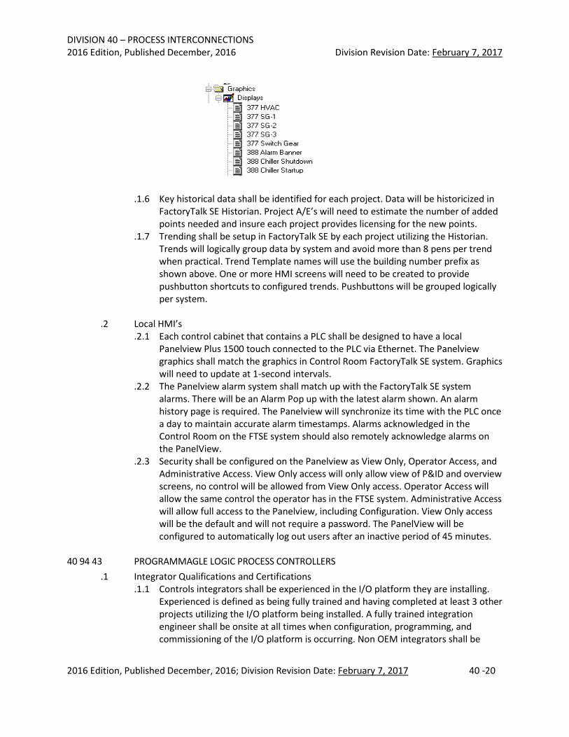
Macros should all have a building number prefix as follows: 1.5.1 McCracken – 069 1.5.2 West Campus Substation – 134 1.5.3 East Regional Chilled Water Plant – 376 1.5.4 Central Power Plant Water Treatment Building – 390 1.5.5 Smith Substation – 127 1.5.6 Generator Building – 377 1.5.7 South Campus Central Chilled Water Plant – 388 1.5.8 OSU Substation – 079
i.e.:
DIVISION 40 – PROCESS INTERCONNECTIONS 2016 Edition, Published December, 2016 Division Revision Date: February 7, 2017
2016 Edition, Published December, 2016; Division Revision Date: February 7, 2017 40 -20
.1.6 Key historical data shall be identified for each project. Data will be historicized in FactoryTalk SE Historian. Project A/E’s will need to estimate the number of added points needed and insure each project provides licensing for the new points.
.1.7 Trending shall be setup in FactoryTalk SE by each project utilizing the Historian. Trends will logically group data by system and avoid more than 8 pens per trend when practical. Trend Template names will use the building number prefix as shown above. One or more HMI screens will need to be created to provide pushbutton shortcuts to configured trends. Pushbuttons will be grouped logically per system.
.2 Local HMI’s
.2.1 Each control cabinet that contains a PLC shall be designed to have a local Panelview Plus 1500 touch connected to the PLC via Ethernet. The Panelview graphics shall match the graphics in Control Room FactoryTalk SE system. Graphics will need to update at 1-second intervals.
.2.2 The Panelview alarm system shall match up with the FactoryTalk SE system alarms. There will be an Alarm Pop up with the latest alarm shown. An alarm history page is required. The Panelview will synchronize its time with the PLC once a day to maintain accurate alarm timestamps. Alarms acknowledged in the Control Room on the FTSE system should also remotely acknowledge alarms on the PanelView.
.2.3 Security shall be configured on the Panelview as View Only, Operator Access, and Administrative Access. View Only access will only allow view of P&ID and overview screens, no control will be allowed from View Only access. Operator Access will allow the same control the operator has in the FTSE system. Administrative Access will allow full access to the Panelview, including Configuration. View Only access will be the default and will not require a password. The PanelView will be configured to automatically log out users after an inactive period of 45 minutes.
40 94 43 PROGRAMMAGLE LOGIC PROCESS CONTROLLERS
.1 Integrator Qualifications and Certifications .1.1 Controls integrators shall be experienced in the I/O platform they are installing.
Experienced is defined as being fully trained and having completed at least 3 other projects utilizing the I/O platform being installed. A fully trained integration engineer shall be onsite at all times when configuration, programming, and commissioning of the I/O platform is occurring. Non OEM integrators shall be
DIVISION 40 – PROCESS INTERCONNECTIONS 2016 Edition, Published December, 2016 Division Revision Date: February 7, 2017
2016 Edition, Published December, 2016; Division Revision Date: February 7, 2017 40 -21
members in good standing with the CSIA (Control System Integrators Association) and follow the CSIA’s Best Practices and Benchmarks.
.1.2 Any project that integrates controls into the Power Plant Boiler DCS (Honeywell Experion) shall use a Honeywell field service representative for programming, SCADA, and operator graphics. Integrators with experience with Honeywell Experion DCS may do their own integration into the Honeywell system if the engineer has attended the following Honeywell training courses:
1.2.1 EXP02 Experion Server Engineering and Configuration 1.2.2 EXP03 Experion Graphics Design and Building 1.2.3 EXP20 Experion Control Execution Environment Controller
.1.3 The integrator shall also have their own licensed copy of Honeywell Experion for
program development. .1.4 Any project that integrates controls into the Utilities FactoryTalk Site Edition DCS
shall use an integrator with FactoryTalk SE training for programming and implementation. Integrators are required to have the following ControlLogix/FactoryTalk SE training:
1.4.1 CCP146 Studio 5000 Logix Designer Level 1: ControlLogix System Fundamentals
1.4.3 CCP143 Studio 5000 Logix Designer Level 3: Project Development 1.4.4 CCV207 FactoryTalk View SE Programming 1.4.5 CCV204 FactoryTalk View ME and Panelview Plus Programming
.2 Plant Systems
.2.1 Boiler Steaming controls shall be specified as Rockwell ControlLogix controllers with redundant processors. All Analog I/O modules shall be HART compatible. Each ControlLogix controller shall have an Allen Bradley Panelview 1500 for local viewing and control of the boiler. The ControlLogix controller shall be integrated into the existing McCracken Ethernet network utilizing a 1756-EN2T card. The redundancy module should synchronize its internal clock to the PLC clock once a day to maintain accurate and synchronized time stamps of events.
.2.2 Boiler Burner Management Systems (BMS) shall be separate from the ControlLogix steaming controls. The BMS shall be Allen Bradley ControlLogix with an L61 Processor and redundant power supplies. Each BMS shall meet NFPA 85 standards. The BMS shall be integrated into the steaming controls via Ethernet. All permissive and interlock signals between the BMS and the steaming controls shall be hard wired 110 VAC digital inputs and outputs. The BMS shall have a local AB Panelview 1500 Operator Interface for burner control and monitoring. The BMS shall comply with NFPA 85 and all other applicable safety standards.
.2.3 Chiller, Cooling Tower, and Plant Auxiliary Equipment controls shall use AB Control Logix. Under no circumstances are OPC interfaces allowed to interface controllers to the FactoryTalk SE system. The selected controller shall communicate via Ethernet back to the FactoryTalk SE system.
.2.4 Remote plants shall use AB ControlLogix. Controllers shall be integrated into the
DIVISION 40 – PROCESS INTERCONNECTIONS 2016 Edition, Published December, 2016 Division Revision Date: February 7, 2017
2016 Edition, Published December, 2016; Division Revision Date: February 7, 2017 40 -22
.2.5 FactoryTalk SE system utilizing TCP/IP communications. Networking equipment shall be provided to utilize redundant fiber optic connections back to the McCracken Power Plant controls network. The remote plant shall be fully automated to both start/stop the remote system automatically or manually from the FactoryTalk SE system at the Power Plant.
.3 Input/Output (I/O) Modules
.3.1 All I/O modules shall have DIN rail mounted remote termination panels and cables. Analog modules shall be HART protocol enabled if available from the OEM or OEM approved 3rd party modules.
.4 Configuration Software
.4.1 If the Utilities Division does not possess the software to configure a new PLC or controller, 3 fully licensed copies of the software shall be specified to be provided with the project. Software shall be Windows 7 64-Bit Enterprise compatible. All software registration shall be transferred over to The Ohio State University.
.4.2 All software programs and content become the property of The Ohio State University. All modules within a software program shall be accessible by the University. All software programs shall be submitted free of any Non-Disclosure Agreements.
.5 Spare Parts
.5.1 Each project shall provide one each of the following spare controller parts: .5.1.1 Controller CPU .5.1.2 Controller Backplane .5.1.3 Controller communication module .5.1.4 One of each type of I/O module .5.1.5 One of each type of remote termination panel and cable .5.1.6 One of each type of relay .5.1.7 One of each type of power supply .5.1.8 One of each type of redundancy module
.6 Warranty and Technical Support
.6.1 Each controller shall be specified to be warranted for 2 years from the date of commissioning. The integrator shall provide a minimum of 2 years technical support for controller programming issues. If the project has provided a controller not made by Honeywell or Rockwell, 2 years of priority telephone technical support from the OEM shall be included as part of the project for controller issues.
40 96 41 PROGRAMMABLE LOGIC PROCESS CONTROLLER PROGRAMMING STANDARDS
PART 1 - Software Design .1 Control Coding Strategy: The following guidelines are intended to improve PLC
operation, aid in the troubleshooting process, and help develop code that can be read and supported once the project is commissioned. They are not intended to inhibit the creativity of programmers. A control strategy is the sequence of steps that must occur
DIVISION 40 – PROCESS INTERCONNECTIONS 2016 Edition, Published December, 2016 Division Revision Date: February 7, 2017
2016 Edition, Published December, 2016; Division Revision Date: February 7, 2017 40 -23
within the program to produce the desired output. When developing a control strategy, the programmer should always plan first and program later. The following guidelines should be used when implementing a control strategy. .1.1 Understand the desired functions of the system. This is accomplished by:
.1.1.1 Reviewing and understanding the Process and Instrumentation Diagrams.
.1.1.2 Reviewing and understanding SAMA diagrams.
.1.1.3 Reviewing and understanding any functional intent documents.
.1.1.4 Reviewing current plant operations with the OSU Automation and Operations team.
.1.2 Review possible control methods. .1.3 Flowchart the process operation. .1.4 Translate the flowchart into PLC code.
.2 The larger a project is, the more organization it will require. It is important to document
the system throughout its development verses once it is installed. This can be accomplished by being well organized from start to finish. .2.1 Flowcharting
.2.1.1 Flowcharting is just one of several techniques used when planning a program after a functional understanding of the process has been completed. Flowcharts should outline the operational process in a sequential manner. Each step in the chart should perform an operation. Flowcharts should never be long and complex. If a process is large and complex, a main flowchart should be developed that would indicate the major functions to be performed in the operation. Then several smaller flowcharts can be used to further describe each of the functions in the main flowchart. Flowcharts are the recommended technique because concepts and details, along with their relationship to each other are quickly clear. General descriptions of sequences and relationships that are difficult to breakdown also become obvious after applied to a flowchart. Finally, it is much easier to discuss and explain an operation to an end user in the form of a flow chart than in ladder logic. Once the process has been flowcharted, the programmer can start developing the ladder code based upon the flowcharts.
.2.2 Code Development
.2.2.1 Code development should not begin until an OSU Controls Engineer has reviewed and commented on the flow charts. All review comments shall be, documented, discussed, and agreed to by the programming team and the OSU Automation Team.
.2.2.2 Unless a process is extremely simple, it should be organized into modules or subroutines. The subroutines can then be ordered according to process flow. Before the actual code is started, each programmer should develop a method for assigning memory (addresses). The recommended method would be to use an excel
DIVISION 40 – PROCESS INTERCONNECTIONS 2016 Edition, Published December, 2016 Division Revision Date: February 7, 2017
2016 Edition, Published December, 2016; Division Revision Date: February 7, 2017 40 -24
spreadsheet. The addresses should be grouped according to function. When assigning addresses, always leave enough room for future expansion. Always group addresses that are sent to an HMI together. This will help through-put of data between the PLC and the HMI. This memory map or address map should be included in the final documentation, for it could assist in troubleshooting and expansion of the control system. The code should be thoroughly documented. Each task or module should have comments describing the general operation. Abbreviations should be avoided if possible. When a description is too long, familiar abbreviations should be used. The following is a list of guidelines that should be followed for every control program. .2.2.2.1 Use flowcharts to develop your code .2.2.2.2 Organize code into functional modules .2.2.2.3 Order the code according to process flow .2.2.2.4 Develop a memory (address) map .2.2.2.5 Group all addresses according to functions .2.2.2.6 Always group addresses that are sent to an HMI .2.2.2.7 Document your code thoroughly .2.2.2.8 Avoid using abbreviations .2.2.2.9 Values that may need changed should always be coded as
variables rather than hard coded constants .2.2.2.10 Avoid master control relays (MCRs) .2.2.2.11 The number of elements in a rung should be limited to what
can be displayed on one screen of the programming terminal .2.2.2.12 Avoid the use of latching coils .2.2.2.13 Each module (subroutine) should have only one entry point,
preferably from the main module .2.2.2.14 Modules (subroutines) should not call other modules .2.2.2.15 Avoid executing multiple messages at the same time by
staggering them to execute on timer and the completion or error of the previous message.
.2.3 General Code Formats
2.3.1 This section provides examples of general rung formats. The following terms will be used in the examples: • Initiator – Starts or begins the rungs execution • Permissive – Prevents the rung from initiating but will not drop it
out. • Interlock – Prevents the rung from initiating and will drop it out • Seal-In – Seals in the output of the rung • Output – The result of the rung execution
2.3.2 Guidelines
.2.3.2.1 The initiator should always be the first element on the rung
.2.3.2.2 The initiator should normally be momentary
DIVISION 40 – PROCESS INTERCONNECTIONS 2016 Edition, Published December, 2016 Division Revision Date: February 7, 2017
2016 Edition, Published December, 2016; Division Revision Date: February 7, 2017 40 -25
.2.3.2.3 The permissive should be to the right of the initiator
.2.3.2.4 Seal-Ins should be in parallel with the permissives
.2.3.2.5 Interlocks should follow the permissives and go before the output
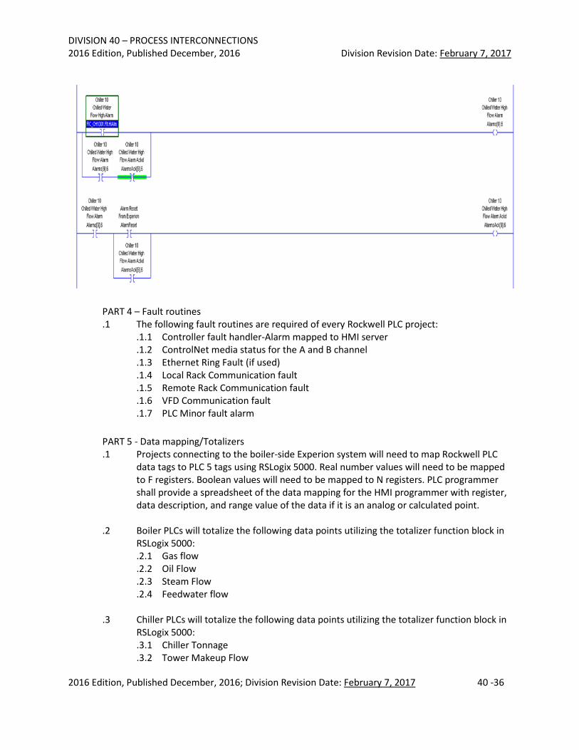
Figure 1.1 - General Rung
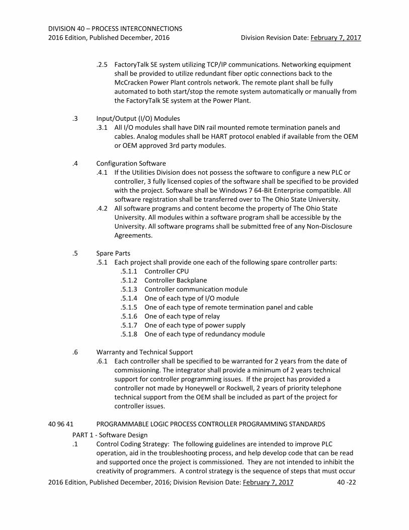
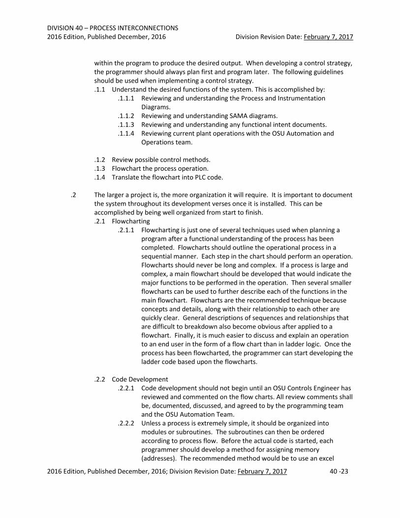
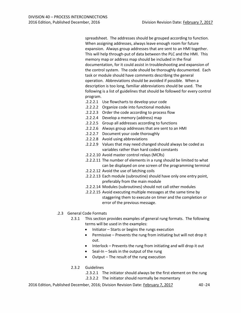
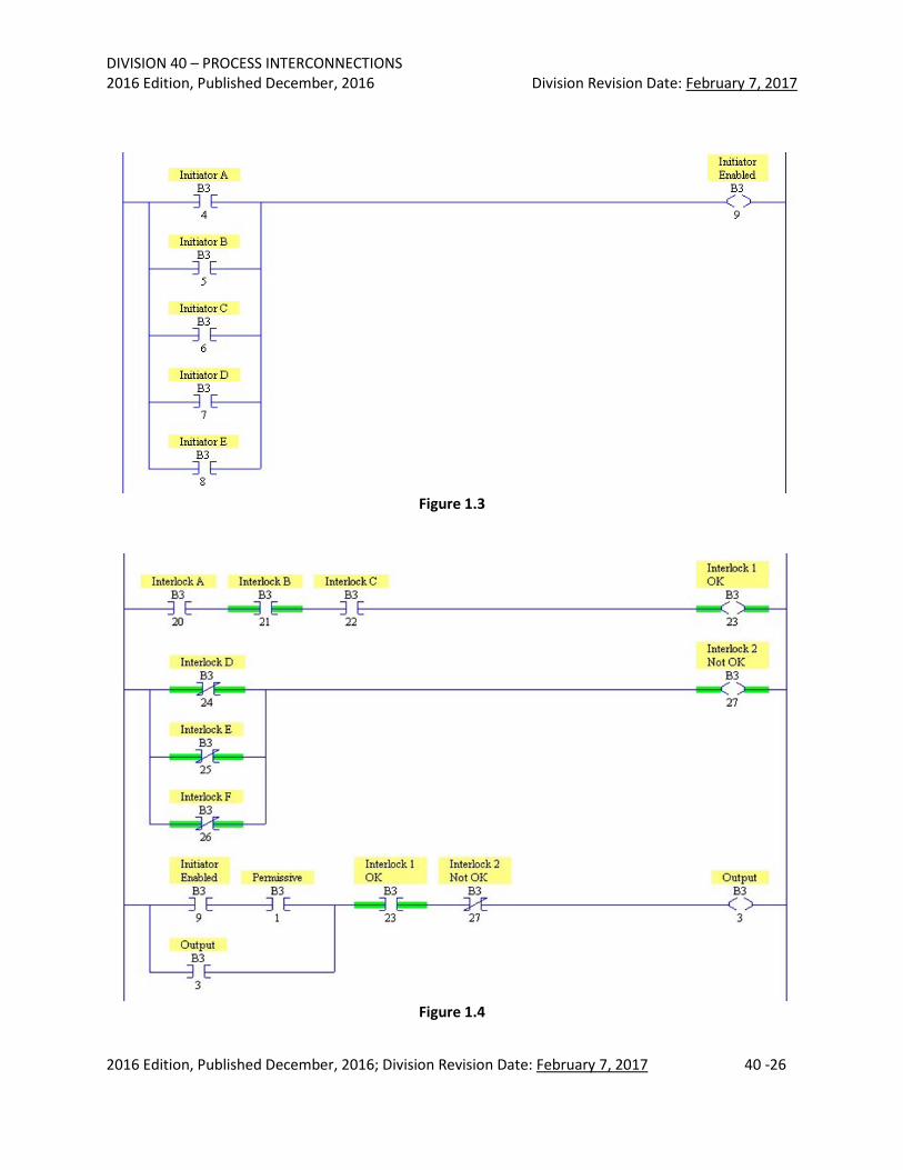
Figures 1.2, 1.3, and 1.4 - General Large Rungs
Avoid programming rungs that contain too many elements. Simplify the rung by dividing it into separate components. Figure 1-2 shows a rung with multiple elements. Figures 1-3 and 1-4 show the equivalent logic, but simplified.
Figure 1.2
DIVISION 40 – PROCESS INTERCONNECTIONS 2016 Edition, Published December, 2016 Division Revision Date: February 7, 2017
2016 Edition, Published December, 2016; Division Revision Date: February 7, 2017 40 -26
Figure 1.3
Figure 1.4
DIVISION 40 – PROCESS INTERCONNECTIONS 2016 Edition, Published December, 2016 Division Revision Date: February 7, 2017
2016 Edition, Published December, 2016; Division Revision Date: February 7, 2017 40 -27
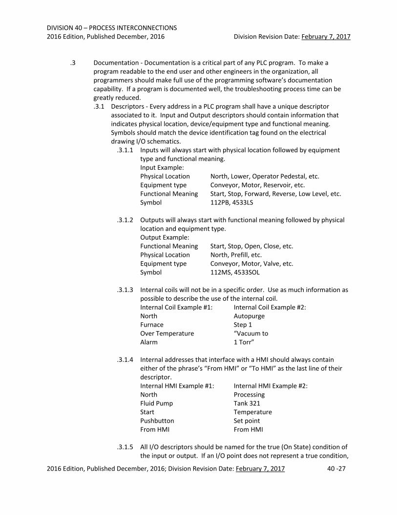
.3 Documentation - Documentation is a critical part of any PLC program. To make a program readable to the end user and other engineers in the organization, all programmers should make full use of the programming software’s documentation capability. If a program is documented well, the troubleshooting process time can be greatly reduced. .3.1 Descriptors - Every address in a PLC program shall have a unique descriptor
associated to it. Input and Output descriptors should contain information that indicates physical location, device/equipment type and functional meaning. Symbols should match the device identification tag found on the electrical drawing I/O schematics.
.3.1.1 Inputs will always start with physical location followed by equipment type and functional meaning. Input Example: Physical Location North, Lower, Operator Pedestal, etc. Equipment type Conveyor, Motor, Reservoir, etc. Functional Meaning Start, Stop, Forward, Reverse, Low Level, etc. Symbol 112PB, 4533LS
.3.1.2 Outputs will always start with functional meaning followed by physical
location and equipment type. Output Example: Functional Meaning Start, Stop, Open, Close, etc. Physical Location North, Prefill, etc. Equipment type Conveyor, Motor, Valve, etc. Symbol 112MS, 4533SOL
.3.1.3 Internal coils will not be in a specific order. Use as much information as
possible to describe the use of the internal coil. Internal Coil Example #1: Internal Coil Example #2: North Autopurge Furnace Step 1 Over Temperature “Vacuum to Alarm 1 Torr”
.3.1.4 Internal addresses that interface with a HMI should always contain
either of the phrase’s “From HMI” or “To HMI” as the last line of their descriptor. Internal HMI Example #1: Internal HMI Example #2: North Processing Fluid Pump Tank 321 Start Temperature Pushbutton Set point From HMI From HMI
.3.1.5 All I/O descriptors should be named for the true (On State) condition of
the input or output. If an I/O point does not represent a true condition,
DIVISION 40 – PROCESS INTERCONNECTIONS 2016 Edition, Published December, 2016 Division Revision Date: February 7, 2017
2016 Edition, Published December, 2016; Division Revision Date: February 7, 2017 40 -28
fail safe devices, the descriptor shall contain “Normally Closed” in the description. Input Example: Physical Location North Equipment type Reservoir Functional Meaning Low Low Level Normally Closed Symbol 423LVS
In the example above, the input would be on when the level is ok and off when the level goes low. This is a common fail safe situation that would be tied to a pump that would be pumping out of the tank. If the wire is cut or the device fails, the logic would stop a pump from emptying a tank and possible damaging the pump.
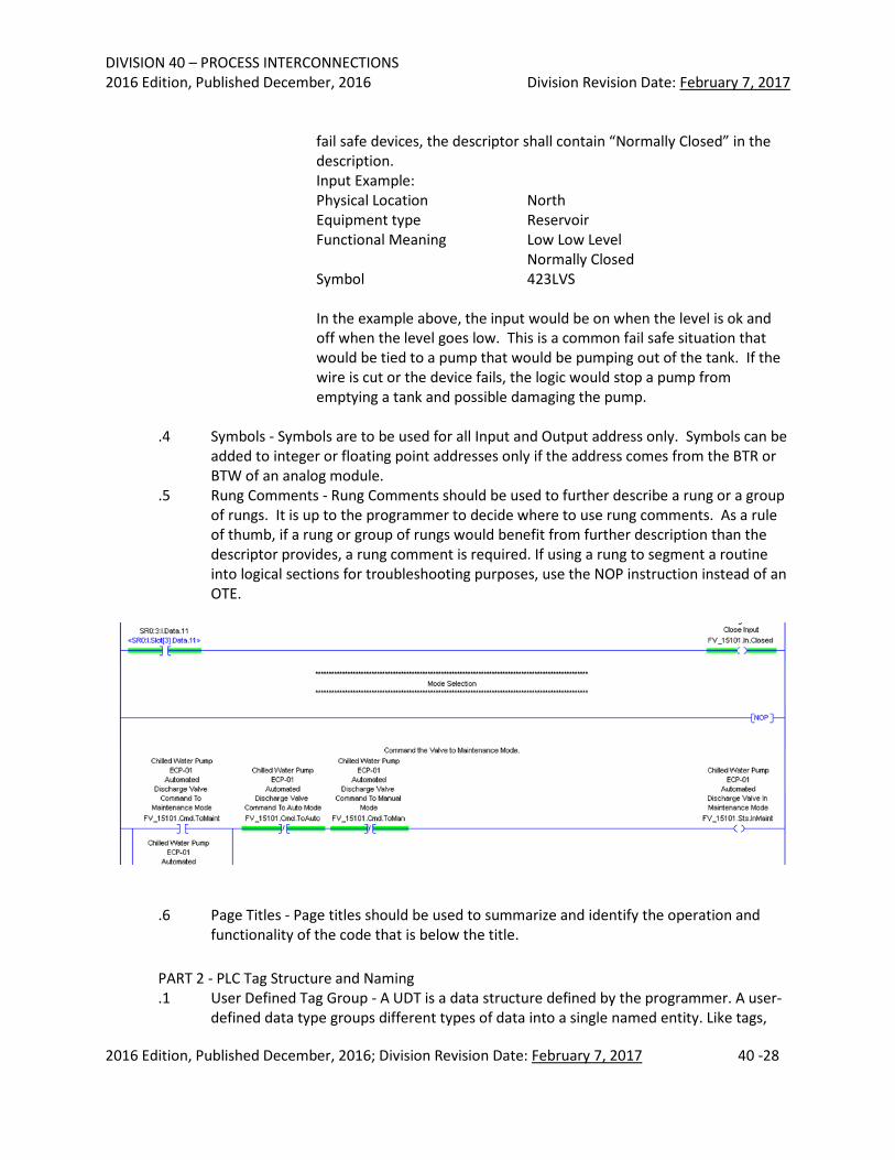
.4 Symbols - Symbols are to be used for all Input and Output address only. Symbols can be
added to integer or floating point addresses only if the address comes from the BTR or BTW of an analog module.
.5 Rung Comments - Rung Comments should be used to further describe a rung or a group of rungs. It is up to the programmer to decide where to use rung comments. As a rule of thumb, if a rung or group of rungs would benefit from further description than the descriptor provides, a rung comment is required. If using a rung to segment a routine into logical sections for troubleshooting purposes, use the NOP instruction instead of an OTE.
.6 Page Titles - Page titles should be used to summarize and identify the operation and functionality of the code that is below the title.
PART 2 - PLC Tag Structure and Naming .1 User Defined Tag Group - A UDT is a data structure defined by the programmer. A user-
defined data type groups different types of data into a single named entity. Like tags,
DIVISION 40 – PROCESS INTERCONNECTIONS 2016 Edition, Published December, 2016 Division Revision Date: February 7, 2017
2016 Edition, Published December, 2016; Division Revision Date: February 7, 2017 40 -29
the members have a name and data type. A UDT is usually used when there is multiple equipment of the same type. A tag is created for each piece of similar equipment with its type being the same UDT. This allows for a common tag structure to be used for all similar equipment. The following are examples of UDT names that were used for a Chiller project.
.2 Tag Naming Convention - The tag names that will be created in the OSU Chiller Control
System PLC software will follow the convention described below. This convention allows tags to be logically organized and facilitates troubleshooting and maintenance of the application. Each tag name will be made up of several fields. These fields when put together will identify the equipment and describe the tags use. These fields will include either a group or single piece of equipment’s identification; an attribute identifier of the equipment and a description of the attribute that further defines its function. This naming convention will be used for tags within a UDT as well as standalone tags. .2.1 Creating Tag Names - In order to create a tag, you will need to identify and define
several items. The first step in creating tags is to organizing the equipment into functional groups. When grouping equipment, try and group equipment that operates as a self-contained system. After a group of equipment is defined it should be assigned an abbreviation that will be used as part of the tag name. Note that only groups that have long descriptions will be abbreviated. Each group of equipment will then be assigned a UDT type. For example, based on the P&ID drawing of the OSU Chillers 8-10, the following groups of equipment can be defined:
Equipment Group Description Equipment Group Abbreviated Identification UDT Type
DIVISION 40 – PROCESS INTERCONNECTIONS 2016 Edition, Published December, 2016 Division Revision Date: February 7, 2017
2016 Edition, Published December, 2016; Division Revision Date: February 7, 2017 40 -30
Condenser Water Pump 11 CondenserPump11 CondWaterPump Condenser Water Pump 12 CondenserPump12 CondWaterPump Condenser Water Pump 13 CondenserPump13 CondWaterPump
.2.2 Once the different groups of equipment are defined, each piece of equipment
that is part of a group should be identified. When identifying this equipment, the P&ID instrument identification tag number should be recorded. This identification number will be used in the tag name to identify the equipment. For example Chiller #8 has the following devices:
Equipment Description Instrument
Identification Tag Number
Chiller #8 Chilled Water Flow Present HS-CH0850 Chiller #8 Chilled Water Inlet Temperature TIT-CH0801 Chiller #8 Chilled Water Outlet Temperature TIT-CH0802 Chiller #8 Tower Water Inlet Temperature TIT-CH0803 Chiller #8 Tower Water Outlet Temperature TIT-CH0804 Chiller #8 Chilled Water Flow FIT-CH0801
.2.3 After all of the equipment has been grouped and identified, the functionality of
the equipment should be identified and recorded. Note that a group of equipment can perform a function as well as a single piece of equipment that is used as part of a group. Below are some sample functions for Chiller #8.
.2.4 Finally, before a tag name can be put together, you will need to define the
attributes that will be used to characterize the group or single piece of equipment. There are four different categories of attributes that can be used to characterize equipment. The first type of attribute is commands. Commands are used to initiate a function. Typical commands are Start, Stop, Open and Close. All commands will be prefixed with the abbreviation of “Cmd”. The second type of attribute is settings. Settings are modifiable variables that are used to control the equipment. Typical settings are set points and alarm limits. All settings will be prefixed with the abbreviation of “Set”. The third type of attribute is values. Values are used to represent an assigned or computed varying quantity. Typical values are temperatures, pressures and flow totals. All values will be prefixed with the abbreviation of “Val”. The fourth type of attribute is statuses. Statuses are used to represent the state or condition of an object. Typical Statuses are opened, closed, and running. All statuses will be prefixed with the abbreviation of “Sts”. Below is a table that summarizes the attributes that are used to characterize equipment.
DIVISION 40 – PROCESS INTERCONNECTIONS 2016 Edition, Published December, 2016 Division Revision Date: February 7, 2017
2016 Edition, Published December, 2016; Division Revision Date: February 7, 2017 40 -31
Category Prefix Abbreviation Description Examples
Commands Cmd Commands are used to initiate a function. Start, Stop, Open, Close
Values Val Values are used to represent an assigned or computed varying quantity.
Temperatures, Pressures, Flow Totals
Settings Set Settings are modifiable variables that are used to control the object. Set points, Alarm Limits
Statuses Sts Statuses are used to represent the state or condition of an object.
Running, Stopped, Opened, Closed
.2.5 Once all of the items above have been completed, you can put them together to
form a descriptive tag name. The following diagrams show the location\order of the fields that make up a tag name.
Example of a tag name associated with a group of equipment not part of a UDT:
Chiller8.Cmd.StartShutdown
Example of a tag name associated with a group of equipment inside a UDT:
Chiller8.Val.ChilledWaterFlow
Example of a tag name associated with a single piece of equipment:
Chiller8.ZTCT1501.Val.Fdbk
.2.6 The following items summarize the tag naming convention: .2.6.1 Tag Names should be organized by grouping equipment based on area
and function. .2.6.2 Use one of the 4 standard attribute types to further define a tag. .2.6.3 The first letter of every word should be capitalized. .2.6.4 Spaces should never be used between words. .2.6.5 Underscores should only be used between words when upper and lower
case text cannot be used. .2.6.6 When using abbreviations, the same abbreviation shall be used
throughout the application and come from the approved abbreviation table.
Equipment Group Identification
Equipment Attribute Type
Attribute Type’s Description
Equipment Group Identification
Equipment Attribute Type
Attribute Type’s Description
Equipment Group Identification
Equipment Attribute Type
Attribute Type’s Description
Single Equipment Identification
DIVISION 40 – PROCESS INTERCONNECTIONS 2016 Edition, Published December, 2016 Division Revision Date: February 7, 2017
2016 Edition, Published December, 2016; Division Revision Date: February 7, 2017 40 -32
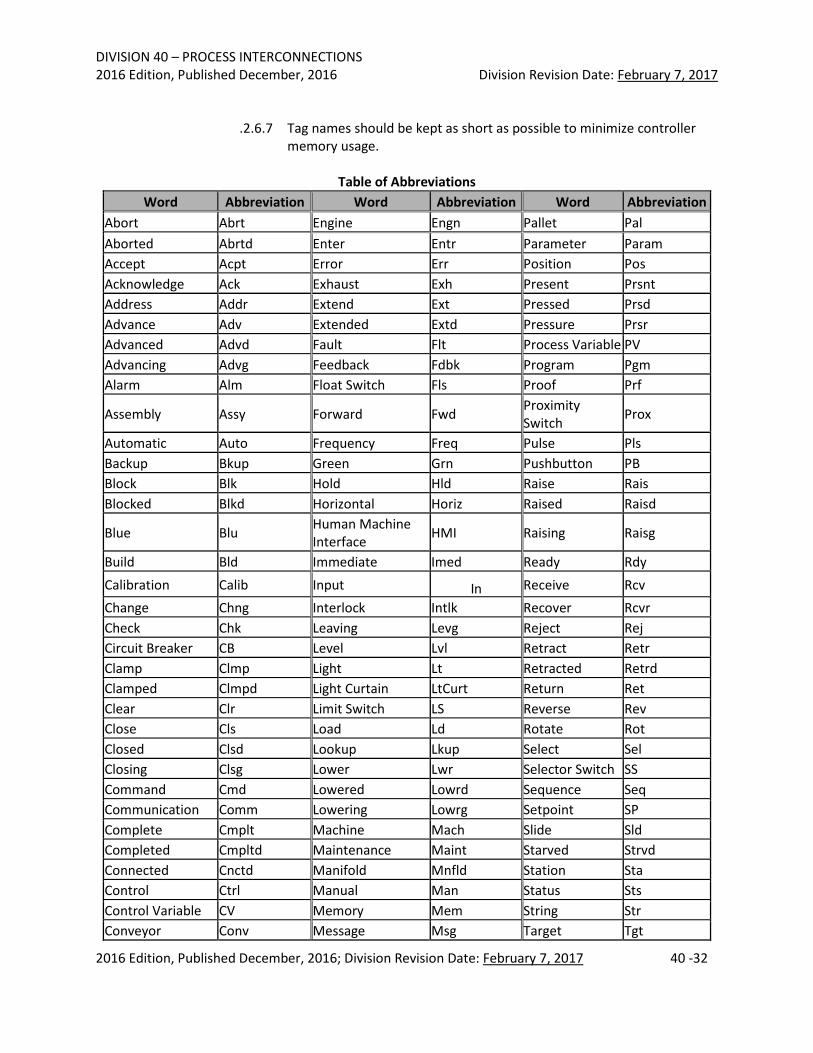
.2.6.7 Tag names should be kept as short as possible to minimize controller memory usage.
Table of Abbreviations
Word Abbreviation Word Abbreviation Word Abbreviation Abort Abrt Engine Engn Pallet Pal Aborted Abrtd Enter Entr Parameter Param Accept Acpt Error Err Position Pos Acknowledge Ack Exhaust Exh Present Prsnt Address Addr Extend Ext Pressed Prsd Advance Adv Extended Extd Pressure Prsr Advanced Advd Fault Flt Process Variable PV Advancing Advg Feedback Fdbk Program Pgm Alarm Alm Float Switch Fls Proof Prf
Assembly Assy Forward Fwd Proximity Switch Prox
Automatic Auto Frequency Freq Pulse Pls Backup Bkup Green Grn Pushbutton PB Block Blk Hold Hld Raise Rais Blocked Blkd Horizontal Horiz Raised Raisd
Blue Blu Human Machine Interface HMI Raising Raisg
Build Bld Immediate Imed Ready Rdy Calibration Calib Input In Receive Rcv Change Chng Interlock Intlk Recover Rcvr Check Chk Leaving Levg Reject Rej Circuit Breaker CB Level Lvl Retract Retr Clamp Clmp Light Lt Retracted Retrd Clamped Clmpd Light Curtain LtCurt Return Ret Clear Clr Limit Switch LS Reverse Rev Close Cls Load Ld Rotate Rot Closed Clsd Lookup Lkup Select Sel Closing Clsg Lower Lwr Selector Switch SS Command Cmd Lowered Lowrd Sequence Seq Communication Comm Lowering Lowrg Setpoint SP Complete Cmplt Machine Mach Slide Sld Completed Cmpltd Maintenance Maint Starved Strvd Connected Cnctd Manifold Mnfld Station Sta Control Ctrl Manual Man Status Sts Control Variable CV Memory Mem String Str Conveyor Conv Message Msg Target Tgt
DIVISION 40 – PROCESS INTERCONNECTIONS 2016 Edition, Published December, 2016 Division Revision Date: February 7, 2017
2016 Edition, Published December, 2016; Division Revision Date: February 7, 2017 40 -33
Word Abbreviation Word Abbreviation Word Abbreviation Counter Ctr Motion Motn Temperature Temp Cycle Cyc Motor Mtr Text Txt Cylinder Cyl Normal Nrml Timeout TOut Deadband DB Delay Dly Number Num Unload Unld Diagnostic Diag Okay OK Vacuum Vac Done Dn Opened Opnd Vertical Vert Downstream Dnstrm Opening Opng Warning Wrn Emergency Emerg Operator Oprtr Water Wtr Emergency Stop E-stop Output Out Write Wrt Enable Enbl Overtravel OTrvl
PART 3 - Alarming .1 Alarm Rationalization - An alarm rationalization process is required of all projects with
HMI’s that have operator interaction. Any alarm that an operator will see will require the operator to take an action. Alarm actions shall be documented with Operations and Procedure manual for the system being installed. Alarms that do not require operator action are defined as events and should never be on an alarm screen. .1.1 All Alarm Names shall have the prefix of the building number as outlined in
section 40 94 33.1.5 .1.2 Alarms will have 4 priorities:
• Urgent o Operator must respond in 60 seconds or less. o Level should only be used for Life-Safety, equipment protection, or
equipment shutdown. Example: High High Water level in a boiler. o FactoryTalk Alarm and Event Priority: 1000.
• High o Operator must respond in 2 minutes or less. o Level should be used to warn of an impending Urgent alarm or to
escalate a Low priority alarm. Example: High water level alarm in a boiler.
o FactoryTalk Alarm and Event Priority: 750. • Low
o Operator response can be greater than 2 minutes. o Level can be used by itself or a as a predecessor to High level alarm.
Example: High conductivity in a boiler. o FactoryTalk Alarm and Event Priority: 250.
• Diagnostic o PLC diagnostic alarms. Example: PLC Major Fault. o Level is not seen by operator on alarm screen but an HMI page should
show the fault. Diagnostic alarms are emailed to the Plant Automation shop via WIN-911FactoryTalk Alarm and Event Priority: 1
DIVISION 40 – PROCESS INTERCONNECTIONS 2016 Edition, Published December, 2016 Division Revision Date: February 7, 2017
2016 Edition, Published December, 2016; Division Revision Date: February 7, 2017 40 -34
o Diagnostic items shall have a special prefix of “H1” in the Alarm Name and use the format: H1 [Building Number] [Alarm Name] i.e.: H1 376 PLC Major Fault Alarm
.1.3 The percentage of alarms per priority should be: • Urgent <5% • High <15% • Low <=80%
.2 Alarm Acknowledgment
.2.1 The Alarm routine shall utilize a single bit from the FactoryTalk SE or Honeywell Experion system to acknowledge and reset alarms per the example below, Figure 3.1. Examples on how to code alarms in the PLC, Figures 3.2 and 3.3.
Figure 3.1
DIVISION 40 – PROCESS INTERCONNECTIONS 2016 Edition, Published December, 2016 Division Revision Date: February 7, 2017
2016 Edition, Published December, 2016; Division Revision Date: February 7, 2017 40 -35
Figure 3.2
Example of a Digital alarm with acknowledge rung
Figure 3.3 (cont. see below)
Example of an analog level alarm with acknowledge rung
DIVISION 40 – PROCESS INTERCONNECTIONS 2016 Edition, Published December, 2016 Division Revision Date: February 7, 2017
2016 Edition, Published December, 2016; Division Revision Date: February 7, 2017 40 -36
PART 4 – Fault routines .1 The following fault routines are required of every Rockwell PLC project:
.1.1 Controller fault handler-Alarm mapped to HMI server
.1.2 ControlNet media status for the A and B channel
.1.3 Ethernet Ring Fault (if used)
.1.4 Local Rack Communication fault
.1.5 Remote Rack Communication fault
.1.6 VFD Communication fault
.1.7 PLC Minor fault alarm
PART 5 - Data mapping/Totalizers .1 Projects connecting to the boiler-side Experion system will need to map Rockwell PLC
data tags to PLC 5 tags using RSLogix 5000. Real number values will need to be mapped to F registers. Boolean values will need to be mapped to N registers. PLC programmer shall provide a spreadsheet of the data mapping for the HMI programmer with register, data description, and range value of the data if it is an analog or calculated point.
.2 Boiler PLCs will totalize the following data points utilizing the totalizer function block in
DIVISION 40 – PROCESS INTERCONNECTIONS 2016 Edition, Published December, 2016 Division Revision Date: February 7, 2017
2016 Edition, Published December, 2016; Division Revision Date: February 7, 2017 40 -37
.3.3 Tower Blowdown Flow
.3.4 Chilled Water loop Makeup flow
.4 Totalizers shall be programmed to reset daily at 12:01 AM.
PART 6 - Programming software .1 Projects shall be developed in Rockwell RSLogix 5000 software, version 20.1 or greater.
Panelview HMI programs shall be developed in the latest version of software available during the controls engineering phase of the project.
40 95 00 PROCESS CONTROL HARDWARE
Specify that process control hardware shall be industrial grade and able to withstand temperatures between 32 and 160°F.
40 95 13 PROCESS CONTROL PANELS AND HARDWARE
.1 Control Panels .1.1 The A/E shall specify that all control panels shall be NEMA 12. In areas where
there is a likelihood of water splashing on the panel, the panel shall be specified to be NEMA 4X. Panels shall be specified to have a built in hasp to allow locking with a padlock. Panels shall also be provided with an external Ethernet port and 3 amp electrical socket that can be secured via a padlock.
.1.2 The A/E shall specify and design for all conduit and tray entry into control panels to be from the bottom or side. Top penetrations are not allowed.
.2 Panel Hardware
.2.1 The A/E shall design all control panels to be equipped with an isolated copper bus bar to connect to the plant instrument grounding system. This is separate from the panel safety ground. The bar shall be sized to accept a 4-0 grounding cable from the field. All IFM shield grounds shall be wired to the instrument ground bus bar.
.3 Panel wiring
.3.1 All wiring inside the panel going to compression type terminals shall be specified to have ferrules installed at the terminal. If ferruling is not practical, all wires shall be specified to be tinned at the termination. All panel and wiring shall be specified to be labeled per the Termination Drawings.
.3.2 Wire colors shall be as follows:
120 VAC HOT Red 120 Neutral White 24 VDC + Blue 24 VDC Common White w/ Blue Stripe Instrument Ground Green w/ Yellow Stripe Safety Ground Green
DIVISION 40 – PROCESS INTERCONNECTIONS 2016 Edition, Published December, 2016 Division Revision Date: February 7, 2017
2016 Edition, Published December, 2016; Division Revision Date: February 7, 2017 40 -38
.3.3 Low power signal and communication wires should not run in the same cable
raceway as control and AC power. Separate as much as possible and avoid parallel runs.
.4 Panel Design
.4.1 Panels shall be designed to accept redundant UPS power feeds for 120 VAC power. Power above 120 VAC is prohibited inside a control panel. Incoming power feeds shall be labeled and have lockable circuit breakers inside the control panel to isolate power.
.4.2 Panels shall be sized to dissipate heat loads inside the panel with ambient exterior temperatures at 104°F. PLC CPU’s shall be designed to be installed in the bottom 1/3 of the panel.
40 95 23 PROCESS CONTROL INPUT/OUTPUT MODULES
.1 Rockwell 1756 I/O modules .1.1 1756 series I/O modules shall use 1492 Interface Modules (IFM) for field-side
wiring. Digital/Analog input and Digital Output IFMs shall be fused. Digital outputs controlling electric motors with a starter larger than NEMA Size 1 shall have an interposing relay between the digital output and the motor starter. Wiring to IFMs shall follow Rockwell’s Industrial Automation Wiring and Grounding Guidelines, publication 1770-4.1.
.1.2 Analog input I/O modules shall be 4-20 mA, HART modules. 1756-IF8H or 1756-IF16H shall be used.
.1.3 Analog output I/O modules shall be 4-20 mA, HART modules. 1756-OF8H shall be used.
.1.4 Digital input and output modules shall be either 120 VAC or 24 VDC, depending on the application. 24 VDC shall not be used in any safety system application. Cards should be the isolated type with no more than 16 points per card.
.2 Honeywell C200 modules
.2.1 Except for specialty cards, such as Modbus interfaces, the Honeywell C200 shall use the same 1756 I/O cards as in Section .1 above. I/O cards shall be purchased from Honeywell due to firmware issues. IFMs can be purchased from Rockwell directly. Module requirements and wiring guidelines are the same as in Section .1 above.
.3 1769 Compact Logix I/O modules
.3.1 1769 series I/O modules shall use 1492 Interface Modules (IFM) for field-side wiring. Digital/Analog input and Digital Output IFMs shall be fused. Digital outputs controlling electric motors with a starter larger than NEMA Size 1 shall have an interposing relay between the digital output and the motor starter. Wiring to IFMs shall follow Rockwell’s Industrial Automation Wiring and Grounding Guidelines, publication 1770-4.1.
.3.2 Analog input I/O modules shall be 4-20 ma, HART modules. 1769sc-IF4IH shall be used.
DIVISION 40 – PROCESS INTERCONNECTIONS 2016 Edition, Published December, 2016 Division Revision Date: February 7, 2017
2016 Edition, Published December, 2016; Division Revision Date: February 7, 2017 40 -39
.3.3 Analog output I/O modules shall be 4-20 ma, HART modules. 1769sc-OF4IH shall be used.
.3.4 Digital input and output modules shall be either 120 VAC or 24 VDC, depending on the application. 24 VDC shall not be used in any safety system application. Cards should be the isolated type with no more than 16 points per card.
40 95 26 PROCESS CONTROL INSTRUMENT AIR PIPING AND DEVICES
.1 Instrument Air Lines .1.1 The A/E shall design and specify that the initial horizontal run shall be a minimum
half inch diameter line (with root valve) terminating with a plugged tee and having drop lines from it, unless otherwise shown, sizes as follows:
Number of instruments supplied
from one branch line Branch line size
2 or less 1/4" NPS Pipe or 3/8" OD Tube 5 or less 3/8" NPS Pipe or 1/2" OD Tube 15 or less 1/2" NPS Pipe or 5/8" OD Tube Over 15 1" NPS Pipe or 1-1/8" OD Tube
Number of control valves supplied
from one branch line Branch line size
1 1/4" NPS Pipe or 3/8" OD Tube 2 3/8" NPS Pipe or 1/2" OD Tube 4 1/2" NPS Pipe or 5/8" OD Tube more than 4 1" NPS Pipe or 1-1/8" OD Tube
.1.2 Instrument air sub-headers from root valves to individual supplies 1 inch and
greater shall be designed by the A/E per OSU Utilities requirements. All control tubing 7/8-inch and smaller shall be in accordance with .2 CONTROL TUBING specified below in this Section.
.1.3 Branch lines shall be connected to the supply headers at the top of the pipe.
.1.4 Individual air filters, air pressure reducing valves with built in relief valve, and 2-inch diameter pressure gauges shall be supplied by the Contractor for each instrument.
.1.5 Main and branch air supply headers shall have blowdown lines and valves at every low point, with a minimum of one blowdown per building elevation. These are to be 1/2-inch nominal pipe with gate valves 48-inches above the floor.
.2 Control tubing
.2.1 All tubing shall be seamless, fully annealed, stainless steel tubing conforming to ASTM A 269, Grade TP 316. The ends shall be plugged before shipment.
.2.2 Fittings shall be flareless compression Type 316 stainless steel. Approved fittings are as follows: • CPI by Park-Hannifin • SWAGELOK by Swagelock
DIVISION 40 – PROCESS INTERCONNECTIONS 2016 Edition, Published December, 2016 Division Revision Date: February 7, 2017
2016 Edition, Published December, 2016; Division Revision Date: February 7, 2017 40 -40
• TYLOK by Tylok International
.3 Instrument air .3.1 Instruments air is defined as compressed air free from contaminants that has a
dew point of -40°F. 40 95 33 PROCESS CONTROL NETWORKS
.1 Prior to installing new network equipment, an engineering study shall be completed by the Project’s A/E to determine the data load and security impacts of the new networking equipment. The person performing the study shall be Network ++ certified or have an equivalent certificate. Study shall encompass the full controls network with special attention paid to multicasting control (IGMP snooping), vLANing, network loading, ACLs, ring redundancy, firewalling, DMZ’s, and routing. Project A/E’s study recommendations shall be included in the installing contractor’s scope for the project.
.2 The A/E shall specify that Contractors will not be allowed to have direct access to the Utilities network with laptops or any other device. Utilities will provide a laptop when needed for project work. All contractor produced files that are to be used on the Utilities network will be uploaded to a Box account, downloaded by Utilities personnel, and scanned for viruses on a computer that is not on the Controls Network. Limited remote access is available to the Utilities network for technical support. Remote access will not be used for checkout, startup, or commissioning activities. The A/E and Contractors shall refer to the Utilities Remote Network Access Policy for more information.
.3 Cabled Process Control Network .3.1 Specify that Ethernet cables shall be CAT6 Shielded Industrial with the following
.3.2 Approved cable: Belden Data Tuff 7953A .3.3 Cables shall be terminated with a shielded, CAT6 compatible RJ-45 plug on one
end only. This end will be the switch end. In the situation where the cable is going from switch to switch, one switch shall have the terminated shield only. The shield drain wire shall be properly installed in this plug. The other end shall be terminated with a standard, CAT6 compatible RJ-45 plug. This end will NOT have the shield terminated. All cables ends shall have proper strain relief devices installed. Cables shall be tested with a Fluke DSX-5000 Cable Analyzer or approved equal. Specify that the contractor shall provide full report on cable testing to the A/E and University.
DIVISION 40 – PROCESS INTERCONNECTIONS 2016 Edition, Published December, 2016 Division Revision Date: February 7, 2017
2016 Edition, Published December, 2016; Division Revision Date: February 7, 2017 40 -41
.4.1.1.1 Comply with ICEA S-83-596 for mechanical properties.
.4.1.1.2 Comply with TIA/EIA-568-B.3 for performance specifications.
.4.1.1.3 Comply with TIA/EIA-492AAAA-B for detailed specifications. .4.1.1.3.1 Plenum Rated, Nonconductive: Type OFNP, complying
with NFPA 262.
.4.1.1.2 Maximum Attenuation: 3.5 dB/km at 850 nm; 1.5 dB/km at 1300 nm.
.4.1.1.3 Minimum Modal Bandwidth: 160 MHz-km at 850 nm; 500 MHz-km at 1300 nm.
.4.1.2 Jacket:
.4.1.2.1 Jacket Color: Aqua for 9/125-micrometer cable
.4.1.2.2 Cable cordage jacket, fiber, unit, and group color shall be according to TIA/EIA-598-B
.4.1.2.3 Imprinted with fiber count, fiber type, and aggregate length at regular intervals not to exceed 40 inches.
.4.2 OPTICAL FIBER CABLE HARDWARE
.4.2.1 Cable Connecting Hardware: Comply with the Fiber Optic Connector Intermateability Standards (FOCIS) specifications of TIA/EIA-604-2, TIA/EIA-604-3-A, and TIA/EIA-604-12. Comply with TIA/EIA-568-B.3. .4.2.1.1 Quick-connect, simplex and duplex, Type SC and Type ST
connectors. Insertion loss not more than 0.75 dB.
.4.2.2 Approved Manufacturers: Corning Cable Systems InfiniCor SX+ Optical Fiber Cabling, Termination Components, and Enclosures.
.5 Wireless Process Control Network
.5.1 No wireless devices of any kind shall be designed, installed, or allowed access on the process control network.
40 95 49 PROCESS CONTROL ROUTERS AND FIREWALLS
.1 Routers shall be redundant with high availability features that will automatically roll over to the backup router on fault or failure. Router shall be designed to be fed from separate UPS power feeds. Current uplink to the building network uplink is CAT 6 cable with a 1 GB speed. Router shall be capable of routing both public and private IP addresses. Router shall have built in VPN capabilities. Device chosen may be a firewall/router combination device. Device shall be approved by the University’s OCIO office as supportable device. Device shall be provided with a 5-year renewable 24/7 support contract. .1.1 Approved Model, specify Dell NSA 3600.
.2 Firewalls shall be a robust model capable of deep packed inspection without
degradation of the 1 GB network throughput. Firewall shall be redundant with high availability features that will automatically roll over to redundant firewall on fault or
DIVISION 40 – PROCESS INTERCONNECTIONS 2016 Edition, Published December, 2016 Division Revision Date: February 7, 2017
2016 Edition, Published December, 2016; Division Revision Date: February 7, 2017 40 -42
failure. Firewall shall be designed to be on separate UPS electrical feeds. The following features shall be included in the firewall: .2.1 Gateway Antivirus .2.2 Anti-spyware .2.3 Intrusion Prevention .2.4 Botnet Prevention .2.5 App Control .2.6 Content filtering .2.7 SYN flood protection .2.8 Multicast Snooping .2.9 Remote log file storage .2.10 Alert messaging via email
.3 Device chosen may be a firewall/router combination device. Device shall be approved
by the University’s OCIO office as supportable device. Device shall be provided with a 5-year renewable 24/7 support contract. .3.1 Approved Model, specify Dell NSA 3600.
40 95 53 PROCESS CONTROL SWITCHES
.1 Control Cabinet Networking Equipment: .1.1 Industrial Managed Ethernet switch, software Layer 2 Basic, store and forward
switching mode 10Mbit/s and 100Mbit/s; Shall be capable of using VLANs, IGMP snooping, https, and ring redundancy.
.1.2.3.2.1 A 75-ohm terminating resistor shall be provided at the each end of a network segment.
.1.2.3.2.2 Allen Bradley 1786-XT
.1.2.3.2.3 Terminations of ControlNet cable shall be done utilizing the Allen Bradley 1786-CTK termination kit.
.1.3 Control Cables:
.1.3.1 No. 14 AWG minimum, type XHHW-2, low smoke zero halogen (LSZH). Nylon conductor jackets and the use of PVC for conductor insulation or jacketing are not acceptable. Multiconductor and jacketed control cable shall conform to ICEA Method 1 Table E2 for individual conductor color coding.
DIVISION 40 – PROCESS INTERCONNECTIONS 2016 Edition, Published December, 2016 Division Revision Date: February 7, 2017
2016 Edition, Published December, 2016; Division Revision Date: February 7, 2017 40 -44
.1.5 Cable installations shall not exceed the manufacturer’s recommended minimum
bend radius or max pulling tension.
.2 Process Control Conduit, Raceway, and Supports .2.1 Conduits shall be designed to be rigid with a 1” minimum size. Conduits with more
than one conductor shall not be filled more than 40%. A pull wire shall be installed in each conduit and a pull station installed every 30 feet. A junction box shall be installed within 3’ of each instrument. The instrument shall be connected to the junction box via Seal Tight. In wet areas, such as cooling towers, there shall be a seal off in the seal tight at the transmitter to protect it from water intrusion. See Division 48 03 04 for detailed installation procedures and requirements.
.3 Process Control Junction Boxes
.3.1 All interior and exterior junction boxes are to be NEMA 3R or better. Junction boxes used on boilers will be NEMA 4X. Conduit entry into junction boxes shall be designed and specified to be from the bottom or the side.