LAUNCH X-431 Mercedes-Benz Diagnosis 1 .Table of Contents INTRODUCTION.................................. 1 HARDWARE CONFIGURATION .................................1 PORTS AND INDICATORS ........................................2 PRINTER OPERATION .............................................3 Mounting Paper ................................ 3 Printing Test Result ........................... 4 EXPLANATION OF BUTTONS ...................................4 BUTTON DESCRIPTIONS.........................................4 CONDITIONS FOR TEST ..........................................4 SELECT DIAGNOSTIC CONNECTOR.........................4 DIAGNOSTIC SOCKET LOCATION ............................5 PIN DEFINITIONS ....................................................5 CONNECTION .........................................................6 OPERATION ......................................... 7 ENTERING FUNCTION M ENU ..................................7 DIGITAL DIAGNOSIS................................................9 ESM SYSTEM....................................................12 Control Unit Version ....................... 12 Read Fault Memory ........................ 13 Clear Fault Memory........................ 13 Read Data Stream ........................... 15 Actuations...................................... 16 ESP SYSTEM ....................................................18 Control Unit Version ....................... 19 Read Fault Memory ........................ 19 Clear Fault Memory........................ 20 Read Data Stream ........................... 21 Actuations...................................... 22 ICM SYSTEM .....................................................23 Control Unit Version ....................... 24 Read Fault Memory ........................ 24 Clear Fault Memory........................ 25 Read Data Stream ........................... 26 Actuations...................................... 27 Control Unit Adaptations ................. 29 AB SYSTEM....................................................... 32 Control Unit Version ........................ 32 Read Fault Memory ......................... 33 Clear Fault Memory ........................ 33 Read Data Stream............................ 35 EIS SYSTEM...................................................... 35 Control Unit Version ........................ 36 Read Fault Memory ......................... 36 Clear Fault Memory ........................ 37 Read Data Stream............................ 38 Actuations ...................................... 39 Control Unit Adaptations .................. 40 ETC SYSTEM .................................................... 49 Control Unit Version ........................ 50 Read Fault Memory ......................... 50 Clear Fault Memory ........................ 51 Read Data Stream............................ 52 Read Data Stream............................ 52 Actuations ...................................... 53 Control Unit Adaptations .................. 55 KG SYSTEM ...................................................... 62 Control Unit Version ........................ 63 Read Fault Memory ......................... 63 Clear Fault Memory ........................ 64 Actuations ...................................... 65 Control Unit Adaptations .................. 69 EIS SYSTEM...................................................... 81 Control Unit Version ........................ 81 Read Fault Memory ......................... 82 Clear Fault Memory ........................ 82 Read Data Stream............................ 84 Actuations ...................................... 84 Control Unit Adaptations .................. 86 AAM SYSTEM ................................................... 91 Control Unit Version ........................ 92 Read Fault Memory ......................... 92 Clear Fault Memory ........................ 93 Control Unit Adaptations .................. 94 EAM SYSTEM ................................................. 103
Transcript
LAUNCH X-431 Mercedes-Benz Diagnosis
1
.Table of Contents
INTRODUCTION.................................. 1
HARDWARE CONFIGURATION .................................1 PORTS AND INDICATORS ........................................2 PRINTER OPERATION .............................................3
Mounting Paper................................ 3 Printing Test Result........................... 4
EXPLANATION OF BUTTONS ...................................4 BUTTON DESCRIPTIONS.........................................4 CONDITIONS FOR TEST ..........................................4 SELECT DIAGNOSTIC CONNECTOR.........................4 DIAGNOSTIC SOCKET LOCATION ............................5 PIN DEFINITIONS ....................................................5 CONNECTION .........................................................6
ENTERING FUNCTION M ENU ..................................7 DIGITAL DIAGNOSIS................................................9 ESM SYSTEM....................................................12
Control Unit Version ....................... 12 Read Fault Memory ........................ 13 Clear Fault Memory........................ 13 Read Data Stream ........................... 15 Actuations...................................... 16
ESP SYSTEM ....................................................18 Control Unit Version ....................... 19 Read Fault Memory ........................ 19 Clear Fault Memory........................ 20 Read Data Stream ........................... 21 Actuations...................................... 22
ICM SYSTEM .....................................................23 Control Unit Version ....................... 24 Read Fault Memory ........................ 24 Clear Fault Memory........................ 25 Read Data Stream ........................... 26 Actuations...................................... 27 Control Unit Adaptations................. 29
AB SYSTEM.......................................................32 Control Unit Version ........................32 Read Fault Memory.........................33 Clear Fault Memory ........................33 Read Data Stream............................35
EIS SYSTEM......................................................35 Control Unit Version ........................36 Read Fault Memory.........................36 Clear Fault Memory ........................37 Read Data Stream............................38 Actuations ......................................39 Control Unit Adaptations..................40
ETC SYSTEM ....................................................49 Control Unit Version ........................50 Read Fault Memory.........................50 Clear Fault Memory ........................51 Read Data Stream............................52 Read Data Stream............................52 Actuations ......................................53 Control Unit Adaptations..................55
KG SYSTEM......................................................62 Control Unit Version ........................63 Read Fault Memory.........................63 Clear Fault Memory ........................64 Actuations ......................................65 Control Unit Adaptations..................69
EIS SYSTEM......................................................81 Control Unit Version ........................81 Read Fault Memory.........................82 Clear Fault Memory ........................82 Read Data Stream............................84 Actuations ......................................84 Control Unit Adaptations..................86
AAM SYSTEM ...................................................91 Control Unit Version ........................92 Read Fault Memory.........................92 Clear Fault Memory ........................93 Control Unit Adaptations..................94
EAM SYSTEM .................................................103
LAUNCH X-431 Mercedes-Benz Diagnosis
2
Control Unit Version ......................104 Read Fault Memory .......................104 Clear Fault Memory.......................105 Actuations.....................................106 Control Unit Adaptations................107
D2B SYSTEM...................................................112 Control Unit Version ......................113 Read Fault Memory .......................113 Clear Fault Memory.......................114 Control Unit Adaptations................115
ABC SYSTEM ..................................................117 Control Unit Version ......................117 Read Fault Memory .......................118 Clear Fault Memory.......................118 Read Data Stream ..........................120 Actuations.....................................121 Control Unit Adaptations................122 Airmatic test..................................124
ME2.0 SYSTEM ...............................................126 Control Unit Version ......................126 Read Fault Memory .......................127 Clear Fault Memory.......................127 Read Data Stream ..........................129 Actuations.....................................130 Control Unit Adaptations................133
LAUNCH X-431 Mercedes-Benz Diagnosis
1
Introduction
Hardware Configuration home The hardware configuration for Mercedes-Benz is as shown in Figure 01.
Figure 01
Configuration for Mercedes-Benz Diagnosis (Figure 01) Item Name Descriptions Item Name Descriptions
1 X-431 main unit
To display operation buttons, test result, help information, etc.
8 [Smart-3] connector
To diagnose vehicles with 16PIN or 8PIN rectangular diagnostic socket
2 MINIPRINTER To print test result. (optional) 9 Power cord
To connect the AC 100-240V outlet and the power adapter.
3 CF cartridge To store diagnostic software and data 10 Cigarette
lighter cable
To get power from the vehicle cigarette lighter
4 USB cable To connect CF card reader/writer and computer
11 Battery cable w/two clips
To get power from the vehicle battery
5 CF card reader/writer
To read or write data on the CF card 12 Power
adapter
To convert 100-240V AC power into 12V DC power.
6 [Smart OBDII-16] connector
To diagnose vehicles with OBDII-16PIN trapezoid diagnostic socket
13 Main cable
To connect the diagnostic connector and SMARTBOX
7 [Mercedes- Benz-38] connector
To diagnose Mercedes-Benz vehicles with 38PIN diagnostic socket
14 SMARTBOX To perform vehicle diagnosis
LAUNCH X-431 Mercedes-Benz Diagnosis
2
Ports and Indicators home See Figure 02 for X-431 connection ports and indicators.
65
13
20
14
7 8
11 12
21
43
9
10
19
18
16
17
15
Figure 02
LAUNCH X-431 Mercedes-Benz Diagnosis
3
1 Printer SEL indicator(printer readiness)
2 Printer power indicator
3 Printer SEL button(printer readiness)
4 Printer FL button(paper feed)
5 Parallel communication port for connecting printer to main unit
6 Power input for printer
7 Parallel communication port for connec ting main unit to printer
8 Power output of main unit.
9 Hotkey of main unit
10 Power switch of the main unit.
11 Power input of main unit 12 Serial communication port of main unit
13 Power output of SMARTBOX 14 Serial communication port of
SMARTBOX 15 SMARTBOX power indicator
16 Indicator to show SMARTBOX sending data to the main unit
17 Indicator to show SMARTBOX receiving data from the main unit
18 Indicator to show SMARTBOX sending data to ECU
19 Indicator to show SMARTBOX receiving data from ECU
20 SMARTBOX data port
Printer Operation home
Mounting Paper home
MINIPRINTER uses heat sensitive paper with size of Φ30×57mm (internal holeΦ7mm). Refer to Figure 03a to Figure 03d for mounting the paper.
1. Open the paper lid on the back of the
printer. See Figure 03a.
Figure 03a
2. Take out the spindle and mount the paper
scroll onto the spindle. See Figure 03b.
Figure 03b
3. Put the paper spindle into the printer with
correct direction. The paper may not be fed if the direction is wrong. See Figure 03b and Figure 03c.
Figure 03c
4. Open the side plate, pull up the pressing
rod and lead the paper into slot. Turn the feed knob clockwise until the paper comes
LAUNCH X-431 Mercedes-Benz Diagnosis
4
out of the outlet. See Figure 03d.
Figure 03d
5. Push down the pressing rod, mount the
side plate, attach the paper lid, and then connect the printer to the X-431 main unit.
Printing Test Result home
There are two indicators on the printer: 1. [SEL]:to show the readiness of the printer. 2. [POWER]: the power indicator of the printer.
If the [SEL] indicator is not lit, you can press the [SEL] button to turn it on and make the printer ready. When the [SEL] indicator is lit, it shows that the printer is ready. Click the [PRINT] button (if it appears) on the screen of X-431 main unit to print the test result.
Explanation of Buttons home
[POWER] Power button
[HOTKEY] Hot key. Press it to calibrate the screen after the machine is turned on. Or press it to enter the vehicle diagnosis interface after X-431 is started.
[SEL] To select the printer. When [SEL] indicator is lit, the printer is ready to print. If [SEL] indicator is not lit, the printer is not able to print.
[FL] Paper- feed button.
Button Descriptions home The main buttons on the operation interface and their functions are as follows: [BACK]: to return to the previous interface. [START]: to do the next operation. [EXIT]: to exit the diagnostic program. [OK]: to confirm and execute. [CANCEL]: to cancel present operation and return to the previous interface. [PAGE UP]: to display the previous page. It is inactive if the current page is the first page. [PAGE DOWN]: to display the next page. It is inactive if the current page is the last page. [HOME]: return to the main interface. [PRINT]: to print the test result. [BOX INFO]: to show the version information of SMARTBOX. [HELP]: to display the help information. [RETRY]: to do the unfinished operation once again.
Conditions for Test home ? The voltage of vehicle battery should be
11-14V. The rated voltage of the X-431 is 12V.
? Turn off all electric devices such as A/C, headlight, stereos etc.
? The throttle should be in the closed position.
? The ignition timer and idle speed should be in the standard range; the water temperature should be 90-110℃ and the transmission oil temperature should be 50-80℃ .
Select Diagnostic connector ? Select the [Benz-38] connector for 38PIN
diagnostic socket, or ? Select [Smart OBDII-16] connector for
16PIN trapezoid diagnostic socket, or ? Select [Smart-3] connector for 16PIN or
8PIN rectangular diagnostic socket. Note: In [Smart-3] connector, the red probe is for power,black probe for grounding and yellow probe for signal.
LAUNCH X-431 Mercedes-Benz Diagnosis
5
Diagnostic Socket Location ? The 16PIN trapezoid diagnostic socket is
located in the cab under the instrument. ? The 38PIN diagnostic socket is in the
engine compartment, passenger side, near the strut tower.
? The 16PIN or 8PIN rec tangular diagnostic socket is located near the firewall of the vehicle.
Pin Definitions home 16PIN Diagnostic Socket The 16PIN trapezoid diagnostic socket is as shown in Figure 04.
Figure 04
PIN definition of 16PIN OBDII diagnostic socket
PIN Definition 1 Two way communication line 2 Not used 3 Not used 4 Body ground 5 Signal ground 6 CAN interior bus (H) 7 Two way communication line 8 Ignition signal 9 Two way communication line
10 Not used 11 Two way commu nication line 12 Two way communication line 13 Two way communication line 14 CAN interior bus (L) 15 Two way communication line 16 Battery voltage
16PIN rectangular diagnostic socket The 16PIN rectangular diagnostic socket is as shown in Figure 05.
Figure 05
PIN definition of 16PIN rectangular diagnostic socket
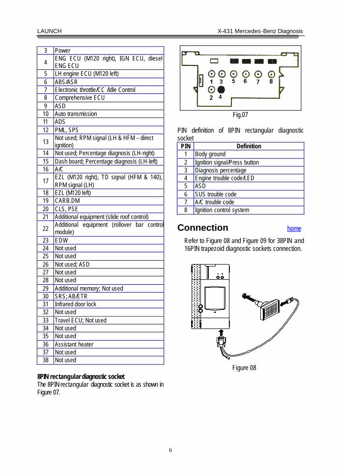
22 Additional equipment (rollover bar control module)
23 EDW 24 Not used 25 Not used 26 Not used; ASD 27 Not used 28 Not used 29 Additional memory; Not used 30 SRS; AB/ETR 31 Infrared door lock 32 Not used 33 Travel ECU; Not used 34 Not used 35 Not used 36 Assistant heater 37 Not used 38 Not used
8PIN rectangular diagnostic socket The 8PIN rectangular diagnostic socket is as shown in Figure 07.
Fig.07
PIN definition of 8PIN rectangular diagnostic socket
PIN Definition 1 Body ground 2 Ignition signal/Press button 3 Diagnosis percentage 4 Engine trouble code/LED 5 ASD 6 SUS trouble code 7 A/C trouble code 8 Ignition control system
Connection home Refer to Figure 08 and Figure 09 for 38PIN and 16PIN trapezoid diagnostic sockets connection.
Figure 08
LAUNCH X-431 Mercedes-Benz Diagnosis
7
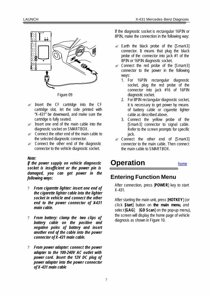
Figure 09
? Insert the CF cartridge into the CF
cartridge slot, let the side printed with “X-431” be downward, and make sure the cartridge is fully seated.
? Insert one end of the main cable into the diagnostic socket on SMARTBOX.
? Connect the other end of the main cable to the selected diagnostic connector.
? Connect the other end of the diagnostic connector to the vehicle diagnostic socket.
Note: If the power supply on vehicle diagnostic socket is insufficient or the power pin is damaged, you can get power in the following ways: ? From cigarette lighter: insert one end of
the cigarette lighter cable into the lighter socket in vehicle and connect the other end to the power connector of X-431 main cable.
? From battery: clamp the two clips of battery cable on the positive and negative poles of battery and insert another end of the cable into the power connector of X-431 main cable.
? From power adapter: connect the power adapter to the 100-240V AC outlet with power cord. Insert the 12V DC plug of power adapter into the power connector of X-431 main cable
If the diagnostic socket is rectangular 16PIN or 8PIN, make the connection in the following way: ? Earth the black probe of the [Smart-3]
connector. It means that plug the black probe of the connector into jack #1 of the 8PIN or 16PIN diagnostic socket.
? Connect the red probe of the [Smart-3] connector to the power in the following ways: 1. For 16PIN rectangular diagnostic
socket, plug the red probe of the connector into jack #16 of 16PIN diagnostic socket.
2. For 8PIN rectangular diagnostic socket, it is necessary to get power by means of battery cable or cigarette lighter cable as described above.
3. Connect the yellow probe of the [Smart-3] connector to signal cable. Refer to the screen prompts for specific jack.
? Connect the other end of [Smart-3] connector to the main cable. Then connect the main cable to SMARTBOX.
Operation home
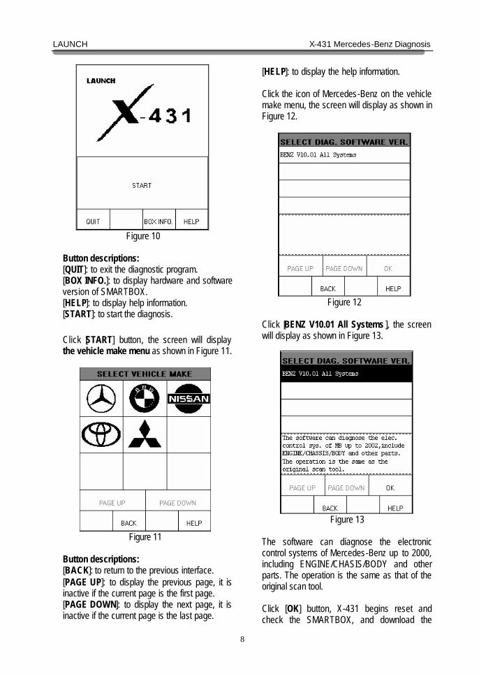
Entering Function Menu After connection, press [POWER] key to start X-431. After starting the main unit, press [HOTKEY] (or click [Start] button on the main menu, and selec t [GAG]→[GD Scan] on the pop-up menu), the screen will display the home page of vehicle diagnosis as shown in Figure 10.
LAUNCH X-431 Mercedes-Benz Diagnosis
8
Figure 10
Button descriptions: [QUIT]: to exit the diagnostic program. [BOX INFO.]: to display hardware and software version of SMARTBOX. [HELP]: to display help information. [START]: to start the diagnosis. Click [START] button, the screen will display the vehicle make menu as shown in Figure 11.
Figure 11
Button descriptions: [BACK]: to return to the previous interface. [PAGE UP]: to display the previous page, it is inactive if the current page is the first page. [PAGE DOWN]: to display the next page, it is inactive if the current page is the last page.
[HELP]: to display the help information. Click the icon of Mercedes-Benz on the vehicle make menu, the screen will display as shown in Figure 12.
Figure 12
Click [BENZ V10.01 All Systems ], the screen will display as shown in Figure 13.
Figure 13
The software can diagnose the electronic control systems of Mercedes-Benz up to 2000, including ENGINE/CHASIS/BODY and other parts. The operation is the same as that of the original scan tool. Click [OK] button, X-431 begins reset and check the SMARTBOX, and download the
LAUNCH X-431 Mercedes-Benz Diagnosis
9
diagnostic program from the CF cartridge. After download, the screen will display as shown in Figure 14.
Figure 14
Button descriptions: [OK]: to go on test.
Digital Diagnosis home When the initialization is finished, click [OK] button, the screen will display the chassis menu of Mercedes-Benz vehicle. See Figure 15.
Figure 15
Click [PAGE DOWN] or [PAGE UP] to find the item corresponding to the tested vehicle. Then
click the item to enter the next menu. Note: ? Now we take [220] (Chassis)→[Gasoline
engine] → [Left-hand steering] →[220.065.S320]→[Control units]→[Drive] as example to explain the diagnosis steps.
? There are too many models and systems for MERCEDES-BENZ. It is not possible and not necessary to list the test steps for all of the models and systems. The test procedures for different models and systems are similar. X-431 displays tips and help information. User can refer to the example or the tips to perform test for different models and systems.
Click [PAGE DOWN] to find [220] and click it. The screen display will be as shown in Figure 16:
Figure 16
Button description: [PRINT]: to print the test result (this function is available only when the word becomes black.).
Click [Gasoline engine], the screen display will be as shown in Figure 17:
LAUNCH X-431 Mercedes-Benz Diagnosis
10
Figure 17
Click [Left-hand steering], the screen will display the 220 chassis menu, as shown in Figure 18:
Figure 18
There are two pages showing the menu of 220 chassis. Click [PAGE DOWN] to display the second page, as shown in Figure 19:
Figure 19
Click [220.065.S320] that in the 220 chassis menu. The screen display will be as shown in Figure 20:
Figure 20
The difference between these two items is in the classification method of system. For easy operation, usually select [Control units]. Click [Control units]. The screen will display the system classification menu, as shown in Figure 21:
LAUNCH X-431 Mercedes-Benz Diagnosis
11
Figure 21
Note: Different chassis may have different system classification menu. Click [Drive], the screen will display the menu of driving system, as shown in Figure 22:
Figure 22
Click [ME2-SFI-Motor electronics]. The screen display will be as shown in Figure 23:
Figure 23
Follow the tips on the screen to switch on the ignition. Then click [OK] button to perform test. Click [CANCEL] to return to the previous interface. Note: ? It may be necessary to start the engine
when testing some types of vehicle. ? If the test fails with the ignition switched
on, you can try the test again after the engine is started.
After turning on the ignition, click [OK]. A moment later, X-431 displays the function menu relating to the tested engine model, as shown in Figure 24:
Figure 24
LAUNCH X-431 Mercedes-Benz Diagnosis
12
Figure25
Figure26
ESM SYSTEM home In ESM system following functions can be selected for running: ? Control unit version ? Read fault memory ? Clear fault memory ? Actual values ? Actuations Click corresponding item to perform the function test.
Control Unit Version home
Click [Control unit version] that in the function menu. The screen will display the information about the control unit version of the test system, as shown in Figure26.
LAUNCH X-431 Mercedes-Benz Diagnosis
13
Figure27
Figure28
Read Fault Memory home
Click [READ FAULT CODE] in the function menu. X-431 starts to scan the fault code. The screen will display the result after the scanning is finished. Figure 27 shows an example. Note: ? The first part of the information is the
fault code; the second part is description of the fault code; the third part is the status of the fault code (there may be no third part for some fault code).
? If there is no fault code in the tested system, the screen will display message “No fault present”.
? After the test result is displayed, click [PRINT] to print out the test result.
? Click [ok] to return to the function menu.
Clear Fault Memory home
Click [Clear fault memory] that in the function menu. The screen will prompt the user to switch off the ignition, as shown in Figure28:
LAUNCH X-431 Mercedes-Benz Diagnosis
14
Figure29
Figure30
After the ignition is turned off, click [OK] to clear the fault memory. The screen will display the massage as shown in Figure29:
After the fault code is cleared, the screen will show the related message. Click [OK] to return to the function menu.
LAUNCH X-431 Mercedes-Benz Diagnosis
15
Figure31
Figure32
Read Data Stream home
Click [Actual values] that in the function menu. The screen will display the list of data streams, as shown in Figure 31 There is more than one page for the list. Click [PAGE UP] or [PAGE DOWN] to turn the page. Figure 31 shows the first page.
.
For example, select 2 items -- [Voltage supply] and [Shift lever] then click [OK]. The screen will display the real- time values of these 4 items, as shown in Figure32:
Note: ? When clicking [DIGITAL] in the interface,
the screen will display the real-time value of the data stream again.
? The three display mode -- [DIGITAL], [GRAPHIC-1] and [GRAPHIC-2] can be switched in turn.
LAUNCH X-431 Mercedes-Benz Diagnosis
16
Figure33
Figure34
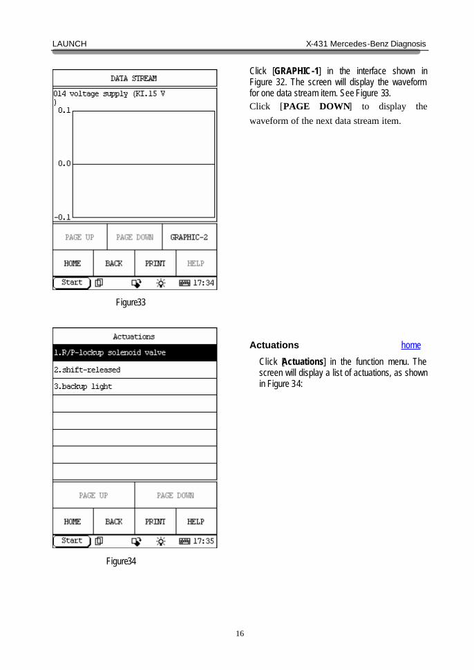
Click [GRAPHIC-1] in the interface shown in Figure 32. The screen will display the waveform for one data stream item. See Figure 33. Click [PAGE DOWN] to display the waveform of the next data stream item.
Actuations home
Click [Actuations] in the function menu. The screen will display a list of actuations, as shown in Figure 34:
LAUNCH X-431 Mercedes-Benz Diagnosis
17
Figure35
Figure36
Click [R/P-lock solenoid valve ] then the screen will display a list of actuations, as shown in Figure35: Click [Shift released] that in figure34 then the screen will display a list of actuations, as shown in Figure36:
LAUNCH X-431 Mercedes-Benz Diagnosis
18
Figure37
Figure38
Click [Shift released] that in figure34 then the screen will display a list of actuations, as shown in Figure37:
ESP SYSTEM home In ESP system following functions can be selected for running: ? Control unit version ? Read fault memory ? Clear fault memory ? Actual values ? Actuations Click corresponding item to perform the function test.
LAUNCH X-431 Mercedes-Benz Diagnosis
19
Figure39
Figure40
Control Unit Version home
Click [Control unit version] that in the function menu. The screen will display the information about the control unit version of the test system, as shown in Figure39:
Read Fault Memory home
Click [READ FAULT CODE] in the function menu. X-431 starts to scan the fault code. The screen will display the result after the scanning is finished. Figure 40 shows an example. Note: ? The first part of the information is the
fault code; the second part is description of the fault code; the third part is the status of the fault code (there may be no third part for some fault code).
? If there is no fault code in the tested system, the screen will display message “No fault present”.
? After the test result is displayed, click [PRINT] to print out the test result.
? Click [BACK] to return to the function menu.
LAUNCH X-431 Mercedes-Benz Diagnosis
20
Figure41
Figure42
Clear Fault Memory home
Click [Clear fault memory] that in the function menu. The screen will prompt the user to switch off the ignition, as shown in Figure41:
After the ignition is turned off, click [OK] to clear the fault memory. The screen will display the massage as shown in Figure42:
LAUNCH X-431 Mercedes-Benz Diagnosis
21
Figure43
Figure44
After the fault code is cleared, the screen will show the related message. Click [OK] to return to the function menu.
Read Data Stream home
Click [Actual values] that in the function menu. The screen will display the list of data streams, as shown in Figure 44: There is more than one page for the list. Click [PAGE UP] or [PAGE DOWN] to turn the page. Figure44 shows the first page.
LAUNCH X-431 Mercedes-Benz Diagnosis
22
Figure45
Figure46
Select the corresponding item the screen will display the real-time values.
Actuations home
Click [Actuations] in the function menu. The screen will display a list of actuations, as shown in Figure46:
LAUNCH X-431 Mercedes-Benz Diagnosis
23
Figure47
Figure48
Click [R/P-lock solenoid valve ] then the screen will display a list of actuations, as shown in Figure47:
ICM SYSTEM home In ICM system following functions can be selected for running: ? Control unit version ? Read fault memory ? Clear fault memory ? Actual values ? Actuations ? Control unit adaptations Click corresponding item to perform the function test.
LAUNCH X-431 Mercedes-Benz Diagnosis
24
Figure49
Figure50
Control Unit Version home
Click [Control unit version] that in the function menu. The screen will display the information about the control unit version of the test system, as shown in Figure49:
Read Fault Memory home
Click [READ FAULT MEMORY] in the function menu. X-431 starts to scan the fault code. The screen will display the result after the scanning is finished. Figure 50 shows an example. Note: ? The first part of the information is the
fault code; the second part is description of the fault code; the third part is the status of the fault code (there may be no third part for some fault code).
? If there is no fault code in the tested system, the screen will display message “No fault present”.
? After the test result is displayed, click [PRINT] to print out the test result.
Click [ok] to return to the function menu
LAUNCH X-431 Mercedes-Benz Diagnosis
25
Figure51
Figure52
Clear Fault Memory home
Click [Clear fault memory] that in the function menu. The screen will prompt the user to switch off the ignition, as shown in Figure51:
After the ignition is turned off, click [OK] to clear the fault memory. The screen will display the massage as shown in Figure52:
LAUNCH X-431 Mercedes-Benz Diagnosis
26
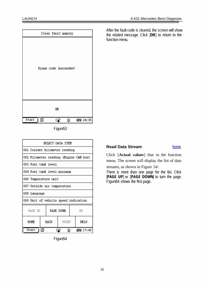
Figure53
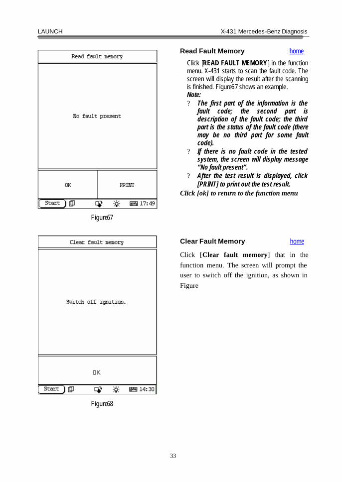
Figure54
After the fault code is cleared, the screen will show the related message. Click [OK] to return to the function menu.
Read Data Stream home
Click [Actual values] that in the function menu. The screen will display the list of data streams, as shown in Figure 54: There is more than one page for the list. Click [PAGE UP] or [PAGE DOWN] to turn the page. Figure54 shows the first page.
LAUNCH X-431 Mercedes-Benz Diagnosis
27
Figure55
Figure56
Select the corresponding item and click [ok] the screen will display the real-time values.
Actuations home
Click [Actuations] in the function menu. The screen will display a list of actuations, as shown in Figure56:
LAUNCH X-431 Mercedes-Benz Diagnosis
28
Figure57
Figure58
Click [Instrument cluster actuations] then the screen will display a list of actuations that can be performed, as shown in Figure57: Click [Display test images on LCD display] that in figure56 then the screen will display a list of actuations that can be performed, as shown in Figure58: [>]More function key
LAUNCH X-431 Mercedes-Benz Diagnosis
29
Figure58
Figure60
Click [Brightness of instrument lighting] that in figure56 then the screen will display a list of actuations that can be performed, as shown in Figure58: [>]Press the key can display more function keys
Control Unit Adaptations home
Warning! Do not perform this operation discretionarily; only the professional can do the control unit adaptations. Click [Control Unit Adaptations] in the function menu. The screen display will be as shown in Figure60:
LAUNCH X-431 Mercedes-Benz Diagnosis
30
Figure61
Figure62
Click [reading coding and transfer to the new control unit]. The screen display will be as shown in Figure61:
Turn off the ignition according to the tips on the screen and then click [OK]. The screen display will be as shown in Figure62:
LAUNCH X-431 Mercedes-Benz Diagnosis
31
Figure63
Figure64
After the ignition is turned on, click [OK]. X-431 starts the control unit adaptation. The screen display will be as shown in Figure63:
Note: ? After the ignition is turned on, click [OK]
to go on the operation. ? Click [CANCEL] to cancel the operation.
Click [Oil service]. The screen display will be as shown in Figure64:
LAUNCH X-431 Mercedes-Benz Diagnosis
32
Figure65
Figure66
AB SYSTEM home In AB system following functions can be selected for running: ? Control unit version ? Read fault memory ? Clear fault memory ? Actual values Click corresponding item to perform the function test.
Control Unit Version home
Click [Control unit version] that in the function menu. The screen will display the information about the control unit version of the test system, as shown in Figure66:
LAUNCH X-431 Mercedes-Benz Diagnosis
33
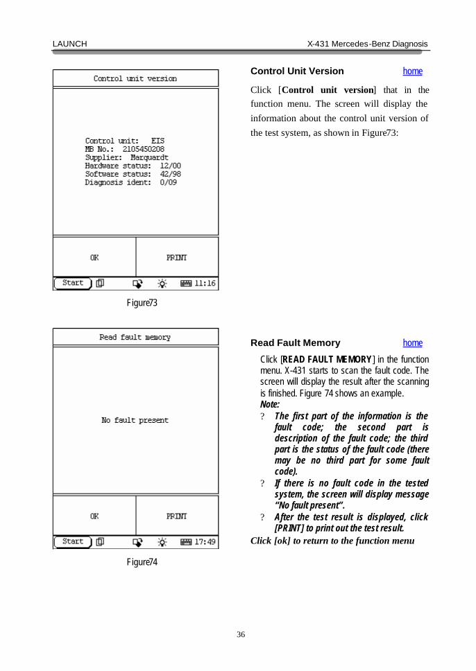
Figure67
Figure68
Read Fault Memory home
Click [READ FAULT MEMORY] in the function menu. X-431 starts to scan the fault code. The screen will display the result after the scanning is finished. Figure67 shows an example. Note: ? The first part of the information is the
fault code; the second part is description of the fault code; the third part is the status of the fault code (there may be no third part for some fault code).
? If there is no fault code in the tested system, the screen will display message “No fault present”.
? After the test result is displayed, click [PRINT] to print out the test result.
Click [ok] to return to the function menu
Clear Fault Memory home
Click [Clear fault memory] that in the function menu. The screen will prompt the user to switch off the ignition, as shown in Figure
LAUNCH X-431 Mercedes-Benz Diagnosis
34
Figure69
Figure70
After the ignition is turned off, click [OK] to clear the fault memory. The screen will display the massage as shown in Figure69: After the fault code is cleared, the screen will show the related message. Click [OK] to return to the function menu.
LAUNCH X-431 Mercedes-Benz Diagnosis
35
Figure71
Figure72
Read Data Stream home
Click [Actual values] that in the function menu. The screen will display the list of data streams, as shown in Figure 71: There is more than one page for the list. Click [PAGE UP] or [PAGE DOWN] to turn the page. Figure 71 shows the first page.
EIS SYSTEM home In EIS system following functions can be selected for running: ? Control unit version ? Read fault memory ? Clear fault memory ? Actual values ? Actuations ? Control unit adaptations Click corresponding item to perform the function test.
LAUNCH X-431 Mercedes-Benz Diagnosis
36
Figure73
Figure74
Control Unit Version home
Click [Control unit version] that in the function menu. The screen will display the information about the control unit version of the test system, as shown in Figure73:
Read Fault Memory home
Click [READ FAULT MEMORY] in the function menu. X-431 starts to scan the fault code. The screen will display the result after the scanning is finished. Figure 74 shows an example. Note: ? The first part of the information is the
fault code; the second part is description of the fault code; the third part is the status of the fault code (there may be no third part for some fault code).
? If there is no fault code in the tested system, the screen will display message “No fault present”.
? After the test result is displayed, click [PRINT] to print out the test result.
Click [ok] to return to the function menu
LAUNCH X-431 Mercedes-Benz Diagnosis
37
Figure75
Figure76
Clear Fault Memory home
Click [Clear fault memory] that in the function menu. The screen will prompt the user to switch off the ignition. After the ignition is turned off, click [OK] to clear the fault memory. The screen will display the massage as shown in Figure75: After the fault code is cleared, the screen will show the related message. Click [OK] to return to the function menu.
LAUNCH X-431 Mercedes-Benz Diagnosis
38
Figure77
Figure78
Read Data Stream home
Click [Actual values] that in the function menu. The screen will display the list of data streams, as shown in Figure 77: There is more than one page for the list. Click [PAGE UP] or [PAGE DOWN] to turn the page. Figure 77 shows the first page Select the corresponding item and click [ok] then the screen will display the real-time values.
LAUNCH X-431 Mercedes-Benz Diagnosis
39
Figure79
Figure80
Actuations home
Click [Actuations] in the function menu. The screen will display a list of actuations, as shown in Figure79:
Click [CAN interior] then the screen will display a list of actuations that can be performed, as shown in Figure80: Click [START] then start actuation test. Click [EXIT] then exit actuation test.
LAUNCH X-431 Mercedes-Benz Diagnosis
40
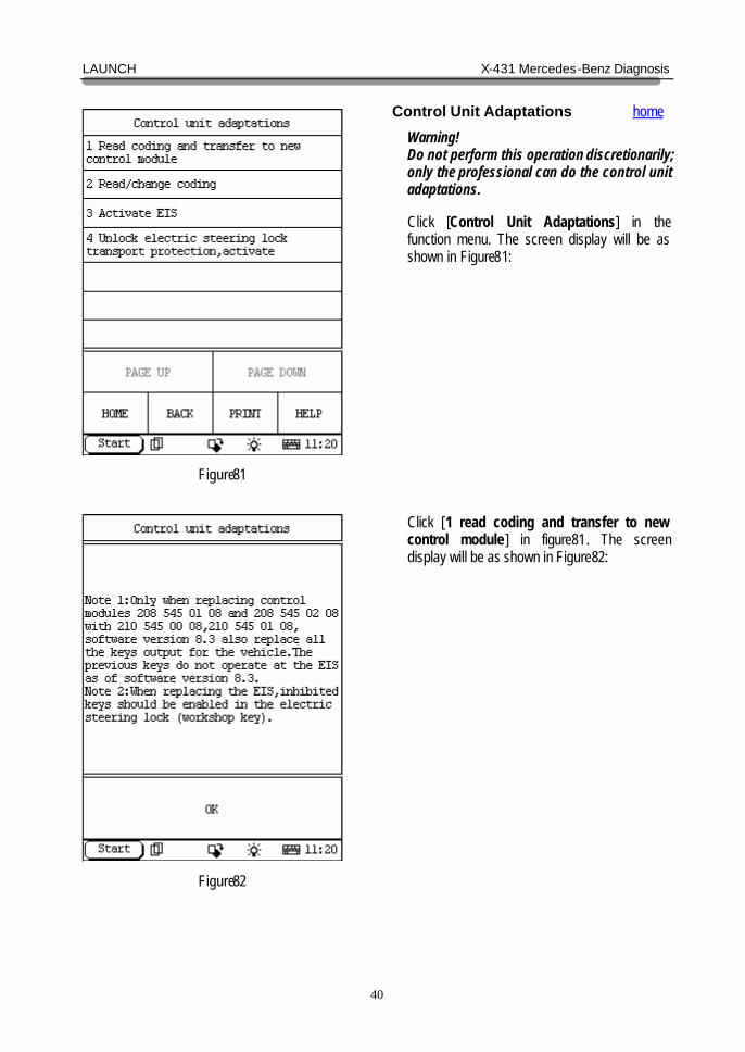
Figure81
Figure82
Control Unit Adaptations home
Warning! Do not perform this operation discretionarily; only the professional can do the control unit adaptations. Click [Control Unit Adaptations] in the function menu. The screen display will be as shown in Figure81:
Click [1 read coding and transfer to new control module] in figure81. The screen display will be as shown in Figure82:
LAUNCH X-431 Mercedes-Benz Diagnosis
41
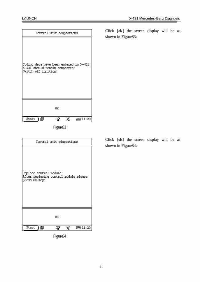
Figure83
Figure84
Click [ok] the screen display will be as shown in Figure83: Click [ok] the screen display will be as shown in Figure84:
LAUNCH X-431 Mercedes-Benz Diagnosis
42
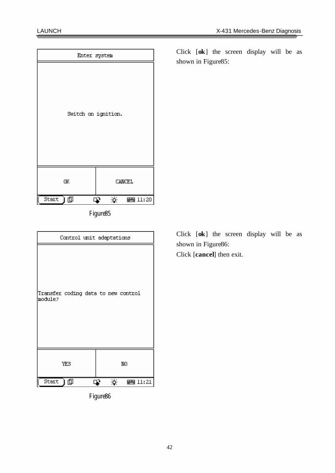
Figure85
Figure86
Click [ok] the screen display will be as shown in Figure85: Click [ok] the screen display will be as shown in Figure86: Click [cancel] then exit.
LAUNCH X-431 Mercedes-Benz Diagnosis
43
Figure87
Figure88
Click [yes] the screen display will be as shown in Figure87: Click [ok] the screen display will be as shown in Figure88:
LAUNCH X-431 Mercedes-Benz Diagnosis
44
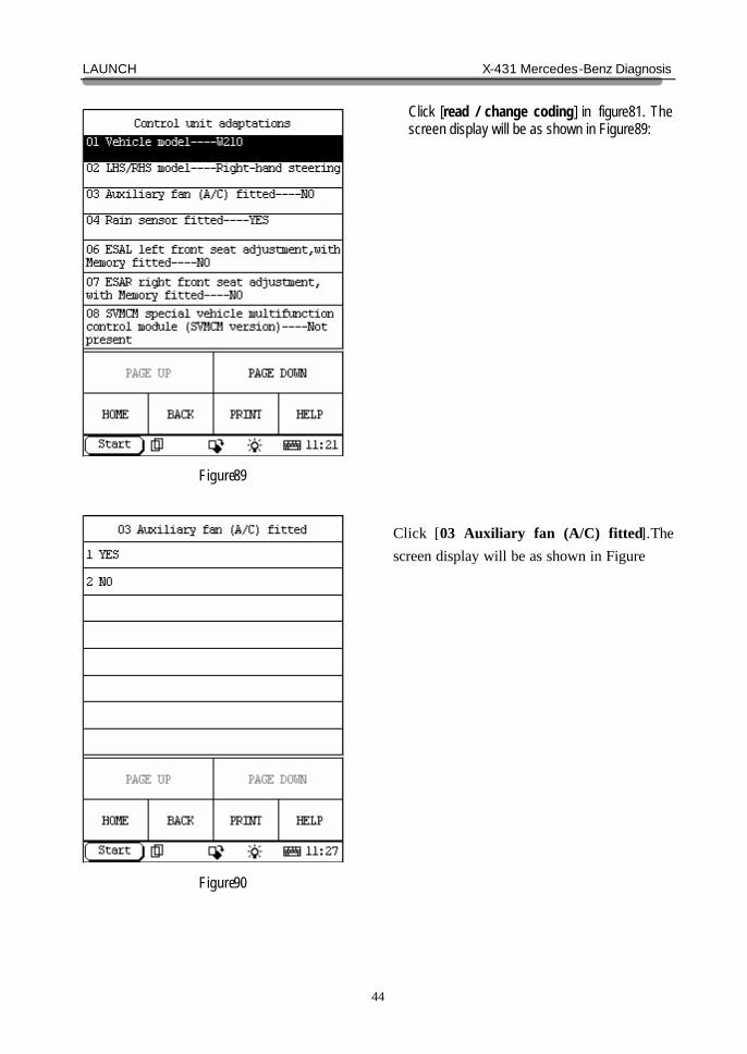
Figure89
Figure90
Click [read / change coding] in figure81. The screen display will be as shown in Figure89:
Click [03 Auxiliary fan (A/C) fitted].The screen display will be as shown in Figure
LAUNCH X-431 Mercedes-Benz Diagnosis
45
Figure91
Figure92
Click [Activate EIS] in figure81. The screen display will be as shown in Figure91: Click [OK] in figure91. The screen display will be as shown in Figure92:
LAUNCH X-431 Mercedes-Benz Diagnosis
46
Figure93
Figure94
Click [OK] in figure92. The screen display will be as shown in Figure: Click [OK] in figure93. The screen display will be as shown in Figure94:
LAUNCH X-431 Mercedes-Benz Diagnosis
47
Figure95
Figure96
Click [OK] in figure94. The screen display will be as show n in Figure: Click [OK] in figure95. The screen display will be as shown in Figure: Click [ok] will return.
LAUNCH X-431 Mercedes-Benz Diagnosis
48
Figure97
Figure98
Click [Unlock electric steering lock transport protection, activate] in figure81. The screen display will be as shown in Figure97: Click [ok] in figure97. The screen display will be as shown in Figure98: Click [yes] will carry out, click [no] then exit.
LAUNCH X-431 Mercedes-Benz Diagnosis
49
Figure99
Figure100
If can’t be carried out, the screen display will be as shown in Figure99: Click [OK] and return.
ETC SYSTEM home In ETC system following functions can be selected for running: ? Control unit version ? Read fault memory ? Clear fault memory ? Actual values ? Actuations ? Control unit adaptations Click corresponding item to perform the function test.
LAUNCH X-431 Mercedes-Benz Diagnosis
50
Figure101
Figure102
Control Unit Version
Click [Control unit version] that in the function menu. The screen will display the information about the control unit version of the test system, as shown in Figure101
Read Fault Memory home
Click [READ FAULT MEMORY] in the function menu. X-431 starts to scan the fault code. The screen will display the result after the scanning is finished. Figure102 shows an example. Note: ? The first part of the information is the
fault code; the second part is description of the fault code; the third part is the status of the fault code (there may be no third part for some fault code).
? If there is no fault code in the tested system, the screen will display message “No fault present”.
? After the test result is displayed, click [PRINT] to print out the test result.
Click [ok] to return to the function menu
LAUNCH X-431 Mercedes-Benz Diagnosis
51
Figure103
Figure104
Clear Fault Memory home
Click [Clear fault memory] that in the function menu. The screen will prompt the user to switch off the ignition. After the ignition is turned off, click [OK] to clear the fault memory. The screen will display the massage as shown in Figure103: After the fault code is cleared, the screen will show the related message. Click [OK] to return to the function menu.
LAUNCH X-431 Mercedes-Benz Diagnosis
52
Figure105
Figure106
Read Data Stream home
Click [Actual values] that in the function menu. The screen will display, as shown in Figure 105
Read Data Stream home
Click [OK] infigure105. The screen will display the list of data streams, as shown in Figure 106: There is more than one page for the list. Click [PAGE UP] or [PAGE DOWN] to turn the page. Figure106 shows the first page.
LAUNCH X-431 Mercedes-Benz Diagnosis
53
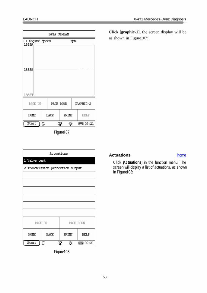
Figure107
Figure108
Click [graphic-1], the screen display will be as shown in Figure107:
Actuations home
Click [Actuations] in the function menu. The screen will display a list of actuations, as shown in Figure108:
LAUNCH X-431 Mercedes-Benz Diagnosis
54
Figure109
Figure110
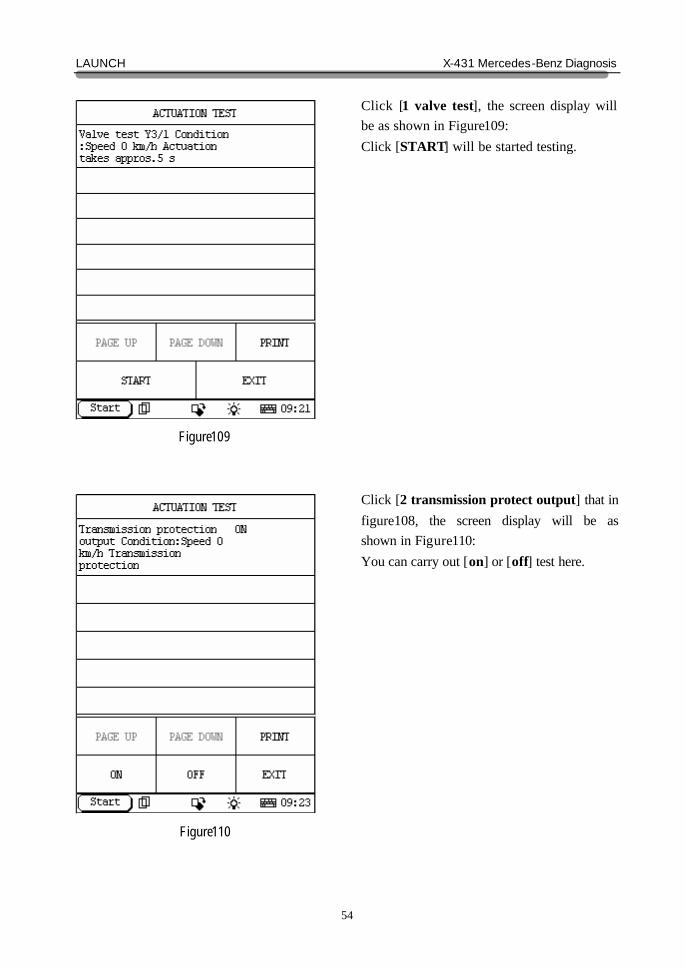
Click [1 valve test], the screen display will be as shown in Figure109: Click [START] will be started testing. Click [2 transmission protect output] that in figure108, the screen display will be as shown in Figure110: You can carry out [on] or [off] test here.
LAUNCH X-431 Mercedes-Benz Diagnosis
55
Figure111
Figure112
Control Unit Adaptations home
Warning! Do not perform this operation discretionarily; only the professional can do the control unit adaptations. Click [Control Unit Adaptations] in the function menu. The screen display will be as shown in Figure111:
Click [Initial startup], the screen display will be as shown in Figure112:
LAUNCH X-431 Mercedes-Benz Diagnosis
56
Figure113
Figure114
Click [ok], the screen display will be as shown in Figure113: Click [cancel] then exit. Click [ok], the screen display will be as shown in Figure114:
LAUNCH X-431 Mercedes-Benz Diagnosis
57
Figure115
Figure116
Click [ok], the screen display will be as shown in Figure115: Click [ok], the screen display will be as shown in Figure116:
LAUNCH X-431 Mercedes-Benz Diagnosis
58
Figure117
Figure118
Click [ok], the screen display will be as shown in Figure117: Click [cancel] then exit. Click [ok], the screen display will be as shown in Figure118: Click [cancel] then exit
LAUNCH X-431 Mercedes-Benz Diagnosis
59
Figure119
Figure120
Click [ok], the screen display will be as shown in Figure119: Click [ok] , the screen display will be as shown in Figure120:
LAUNCH X-431 Mercedes-Benz Diagnosis
60
Figure121
Figure122
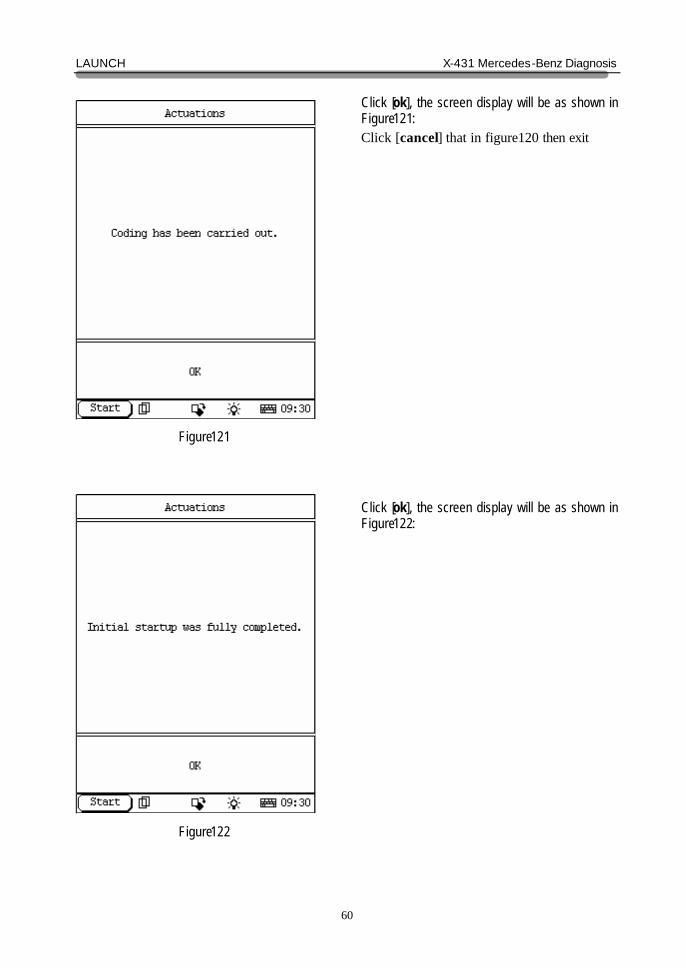
Click [ok], the screen display will be as shown in Figure121: Click [cancel] that in figure120 then exit Click [ok], the screen display will be as shown in Figure122:
LAUNCH X-431 Mercedes-Benz Diagnosis
61
Figure123
Figure124
Click [adaptation data] that in figure111 , the screen will display the referenced data as shown in Figure123: Click [resetting of adaptation data] that in figure111, the screen display will be as shown in Figure124: Click [cancel] then exit Click [ok] start to reset.
LAUNCH X-431 Mercedes-Benz Diagnosis
62
Figure125
Figure126
Click [ok] in here, complete resetting.
KG SYSTEM home In KG system following functions can be selected for running: ? Control unit version ? Read fault memory ? Clear fault memory ? Actuations ? Control unit adaptations Click corresponding item to perform the function test.
LAUNCH X-431 Mercedes-Benz Diagnosis
63
Figure127
Figure128
Control Unit Version home
Click [Control unit version] that in the function menu. The screen will display the information about the control unit version of the test system, as shown in Figure127
Read Fault Memory home
Click [READ FAULT MEMORY] in the function menu. X-431 starts to scan the fault code. The screen will display the result after the scanning is finished. Figure128 shows an example. Note: ? The first part of the information is the
fault code; the second part is description of the fault code; the third part is the status of the fault code (there may be no third part for some fault code).
? If there is no fault code in the tested system, the screen will display message “No fault present”.
? After the test result is displayed, click [PRINT] to print out the test result.
Click [ok] to return to the function menu
LAUNCH X-431 Mercedes-Benz Diagnosis
64
Figure129
Figure130
Clear Fault Memory home
Click [Clear fault memory] that in the function menu. The screen will prompt the user to switch off the ignition, as shown in Figure129: After the ignition is turned off, click [OK] to clear the fault memory. The screen will display the massage as shown in Figure130:
LAUNCH X-431 Mercedes-Benz Diagnosis
65
Figure131
Figure132
After the fault code is cleared, the screen will show the related message. Click [OK] to return to the function menu.
Actuations home
Click [Actuations] in the function menu. The screen will display a list of actuations, as shown in Figure132:
LAUNCH X-431 Mercedes-Benz Diagnosis
66
Figure133
Figure134
Click [activation of lift solenoids], the screen will display a list of actuations, as shown in Figure133: Click [1 L12], the screen display as show in the figure:
LAUNCH X-431 Mercedes-Benz Diagnosis
67
Figure135
Figure136
Click [ok], the screen display as show in the figure135: [F3] Reset voltage value of lift solenoid [F4] Actuation of lift solenoid Click [transmitter card and antenna test ] that in figure132, the screen will display a list of actuations, as shown in Figure136:
LAUNCH X-431 Mercedes-Benz Diagnosis
68
Figure137
Figure138
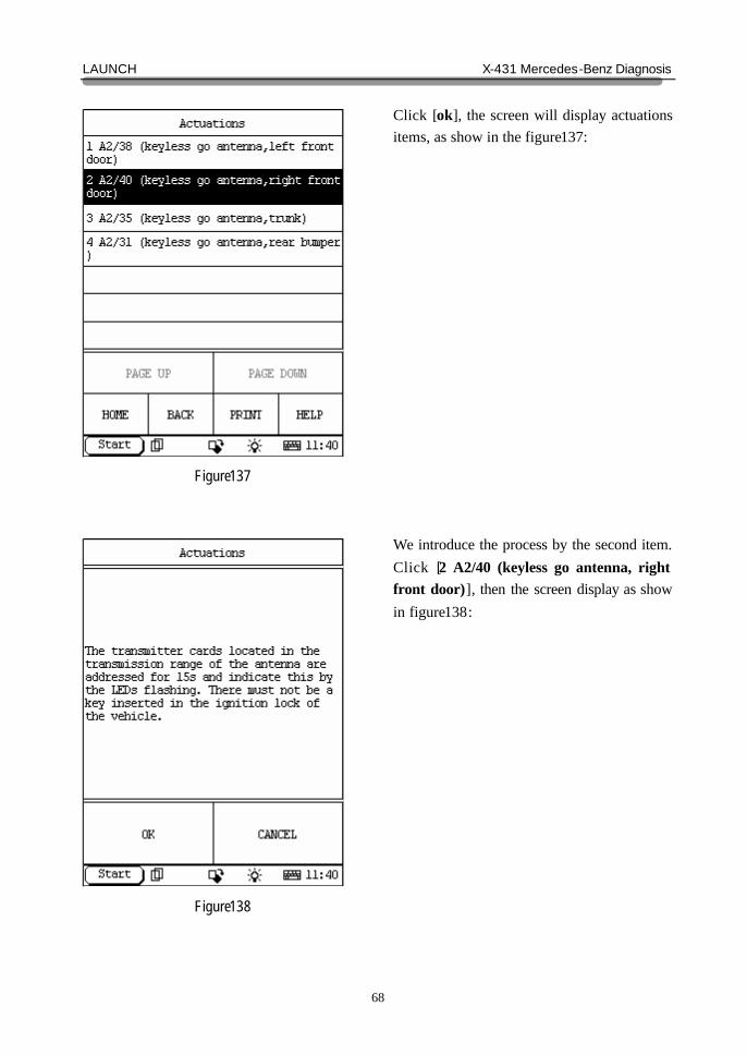
Click [ok], the screen will display actuations items, as show in the figure137: We introduce the process by the second item. Click [2 A2/40 (keyless go antenna, right front door)], then the screen display as show in figure138:
LAUNCH X-431 Mercedes-Benz Diagnosis
69
Figure139
Figure140
Click [ok] then the screen display as show in figure139: It may take minutes.
Control Unit Adaptations home
Warning! Do not perform this operation discretionarily; only the professional can do the control unit adaptations. Click [Control Unit Adaptations] in the function menu. The screen display will be as shown in Figure140:
LAUNCH X-431 Mercedes-Benz Diagnosis
70
Figure141
Figure142
Click [Initial startup] then the screen display as show in figure141: Click [control unit replacement] that in figure140 then the screen display as show in figure142:
LAUNCH X-431 Mercedes-Benz Diagnosis
71
Figure143
Figure144
Click [assign transmitter to key track ] then the screen display as show in figure143: We introduce the process by the first item. Click [300 Transmitter card 2 1for keyless go key track ], then the screen display as show in figure144:
LAUNCH X-431 Mercedes-Benz Diagnosis
72
Figure145
Figure146
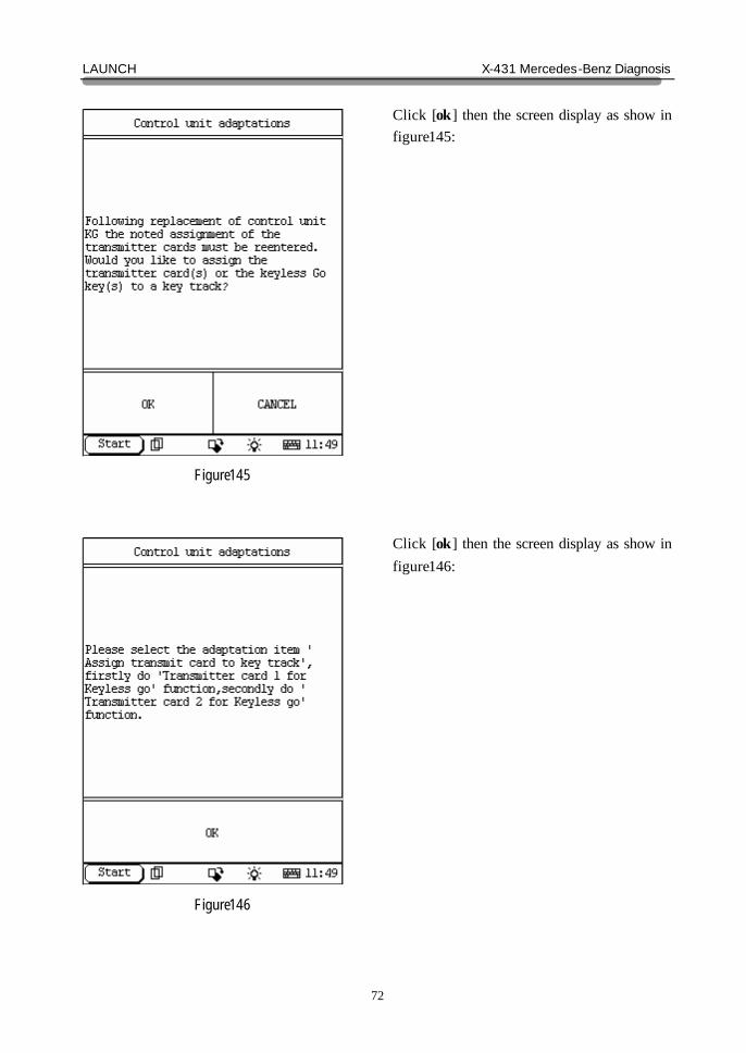
Click [ok] then the screen display as show in figure145: Click [ok] then the screen display as show in figure146:
LAUNCH X-431 Mercedes-Benz Diagnosis
73
Figure147
Figure148
Click [ok] then the screen display as show in figure147: Click [ok] then the screen display as show in figure148:
LAUNCH X-431 Mercedes-Benz Diagnosis
74
Figure149
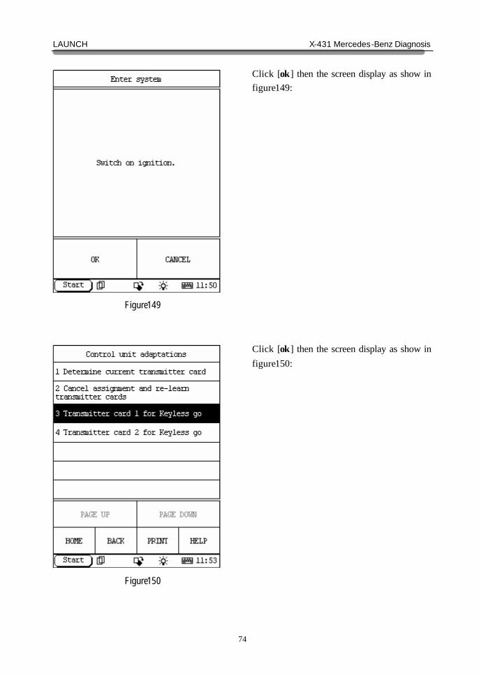
Figure150
Click [ok] then the screen display as show in figure149: Click [ok] then the screen display as show in figure150:
LAUNCH X-431 Mercedes-Benz Diagnosis
75
Figure151
Figure152
We introduce the process by the third item. Click [Transmitter card 1 for keyless go], then the screen display as show in figure151: Click [ok] then the screen display as show in figure152:
LAUNCH X-431 Mercedes-Benz Diagnosis
76
Figure153
Figure154
Click [ok] then the screen display as show in figure153: Click [ok] then the screen display as show in figure154:
LAUNCH X-431 Mercedes-Benz Diagnosis
77
Figure155
Figure156
Click [ok] then the screen display as show in figure155: Click [ok] then the screen display as show in figure156: You can carry out [F3] or [F4] in here.
LAUNCH X-431 Mercedes-Benz Diagnosis
78
Figure157
Figure158
We introduce the process by the F3 button. Click [F3], then the screen display as show in figure157: Click [ok] then the screen display as show in figure158:
LAUNCH X-431 Mercedes-Benz Diagnosis
79
Figure159
Figure160
Input the right key track and close the keyboard, click [ok], then the screen display as show in figure159: Click [ok] then the screen display as show in figure160:
LAUNCH X-431 Mercedes-Benz Diagnosis
80
Figure161
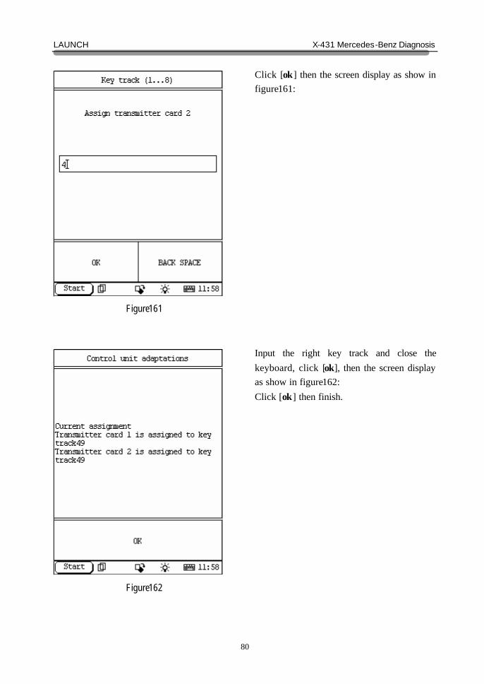
Figure162
Click [ok] then the screen display as show in figure161: Input the right key track and close the keyboard, click [ok], then the screen display as show in figure162: Click [ok] then finish.
LAUNCH X-431 Mercedes-Benz Diagnosis
81
Figure163
Figure164
EIS SYSTEM home In EIS system following functions can be selected for running: ? Control unit version ? Read fault memory ? Clear fault memory ? Actual values ? Actuations ? Control unit adaptations Click corresponding item to perform the function test.
Control Unit Version home
Click [Control unit version] that in the function menu. The screen will display the information about the control unit version of the test system, as shown in Figure164:
LAUNCH X-431 Mercedes-Benz Diagnosis
82
Figure165
Figure166
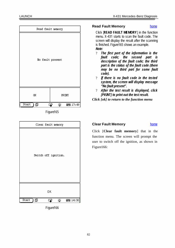
Read Fault Memory home
Click [READ FAULT MEMORY] in the function menu. X-431 starts to scan the fault code. The screen will display the result after the scanning is finished. Figure165 shows an example. Note: ? The first part of the information is the
fault code; the second part is description of the fault code; the third part is the status of the fault code (there may be no third part for some fault code).
? If there is no fault code in the tested system, the screen will display message “No fault present”.
? After the test result is displayed, click [PRINT] to print out the test result.
Click [ok] to return to the function menu
Clear Fault Memory home
Click [Clear fault memory] that in the function menu. The screen will prompt the user to switch off the ignition, as shown in Figure166:
LAUNCH X-431 Mercedes-Benz Diagnosis
83
Figure167
Figure168
After the ignition is turned off, click [OK] to clear the fault memory. The screen will display the massage as shown in Figure167: After the fault code is cleared, the screen will show the related message. Click [OK] to return to the function menu.
LAUNCH X-431 Mercedes-Benz Diagnosis
84
Figure169
Figure170
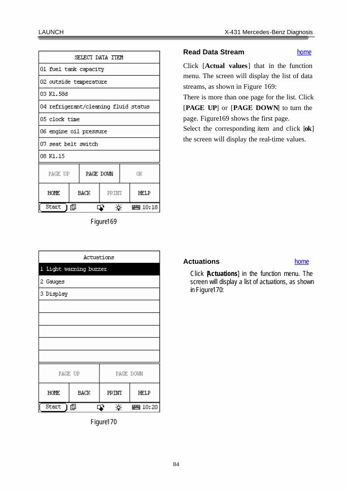
Read Data Stream home
Click [Actual values] that in the function menu. The screen will display the list of data streams, as shown in Figure 169: There is more than one page for the list. Click [PAGE UP] or [PAGE DOWN] to turn the page. Figure169 shows the first page. Select the corresponding item and click [ok] the screen will display the real-time values.
Actuations home
Click [Actuations] in the function menu. The screen will display a list of actuations, as shown in Figure170:
LAUNCH X-431 Mercedes-Benz Diagnosis
85
Figure171
Figure172
Click [Light warning buzzer] then the screen will display as shown in Figure171: Click [on] you can test the light warning buzzer. Click [gauges] that in figure170 then the screen will display as shown in Figure172 Click [on] you can test the gauges.
LAUNCH X-431 Mercedes-Benz Diagnosis
86
Figure173
Figure174
Click [Display] that in figure170 then the screen will display as shown in Figure173: Click [on] or [off] you can test the display.
Control Unit Adaptations home
Warning! Do not perform this operation discretionarily; only the professional can do the control unit adaptations. Click [Control Unit Adaptations] in the function menu. The screen display will be as shown in Figure174:
LAUNCH X-431 Mercedes-Benz Diagnosis
87
Figure175
Figure176
Click [ok] then the screen display as show in figure175: Click [1 Read coding and transfer to new module] then the screen display as show in figure176:
LAUNCH X-431 Mercedes-Benz Diagnosis
88
Figure177
Figure178
Click [ok] then the screen display as show in figure177: Click [ok] then the screen display as show in figure178: Click [yes], coding data will be transferred. Click [no] will return.
LAUNCH X-431 Mercedes-Benz Diagnosis
89
Figure179
Figure180
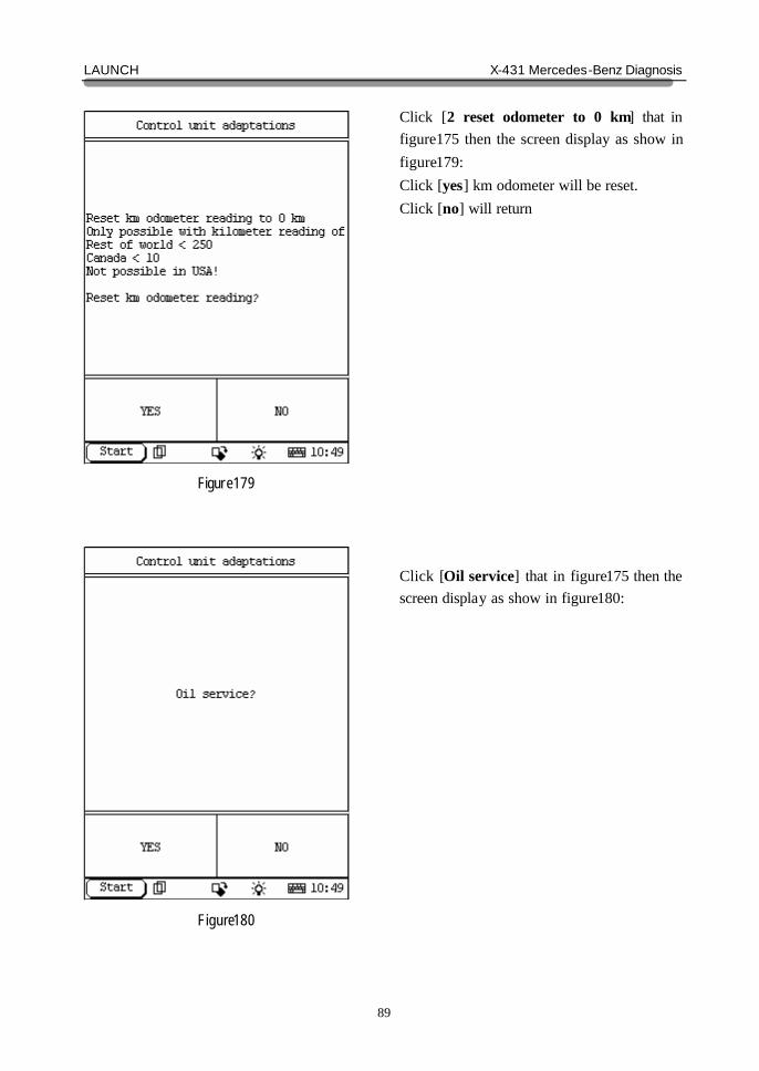
Click [2 reset odometer to 0 km] that in figure175 then the screen display as show in figure179: Click [yes] km odometer will be reset. Click [no] will return Click [Oil service] that in figure175 then the screen display as show in figure180:
LAUNCH X-431 Mercedes-Benz Diagnosis
90
Figure181
Figure182
Click [Mileage as read from odometer forward] then the screen display as show in figure181: Click [yes] then the screen display as show in figure182:
LAUNCH X-431 Mercedes-Benz Diagnosis
91
Figure183
Figure184
Input the right number then click [ok], the screen display as show in figure: Click [yes] completely.
AAM SYSTEM home In AAM system following functions can be selected for running: ? Control unit version ? Read fault memory ? Clear fault memory ? Control unit adaptations Click corresponding item to perform the function test.
LAUNCH X-431 Mercedes-Benz Diagnosis
92
Figure185
Figure186
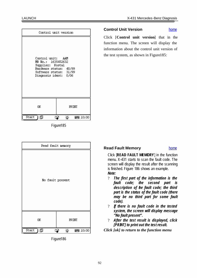
Control Unit Version home
Click [Control unit version] that in the function menu. The screen will display the information about the control unit version of the test system, as shown in Figure185:
Read Fault Memory home
Click [READ FAULT MEMORY] in the function menu. X-431 starts to scan the fault code. The screen will display the result after the scanning is finished. Figure 186 shows an example. Note: ? The first part of the information is the
fault code; the second part is description of the fault code; the third part is the status of the fault code (there may be no third part for some fault code).
? If there is no fault code in the tested system, the screen will display message “No fault present”.
? After the test result is displayed, click [PRINT] to print out the test result.
Click [ok] to return to the function menu
LAUNCH X-431 Mercedes-Benz Diagnosis
93
Figure187
Figure188
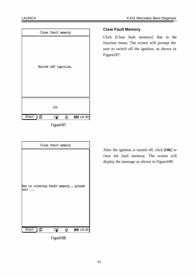
Clear Fault Memory
Click [Clear fault memory] that in the function menu. The screen will prompt the user to switch off the ignition, as shown in Figure187: After the ignition is turned off, click [OK] to clear the fault memory. The screen will display the massage as shown in Figure188:
LAUNCH X-431 Mercedes-Benz Diagnosis
94
Figure189
Figure190
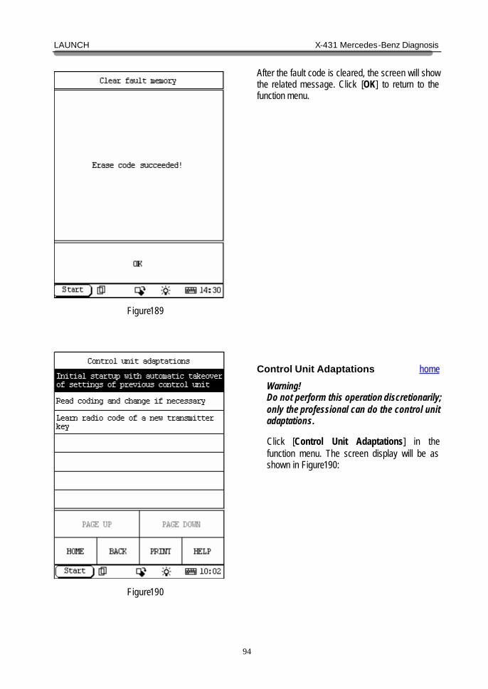
After the fault code is cleared, the screen will show the related message. Click [OK] to return to the function menu.
Control Unit Adaptations home
Warning! Do not perform this operation discretionarily; only the professional can do the control unit adaptations. Click [Control Unit Adaptations] in the function menu. The screen display will be as shown in Figure190:
LAUNCH X-431 Mercedes-Benz Diagnosis
95
Figure191
Figure192
Click [Initial startup with automatic takeover of settings of previous control unit] then the screen display as show in figure191: Click [yes] then the screen display as show in figure192:
LAUNCH X-431 Mercedes-Benz Diagnosis
96
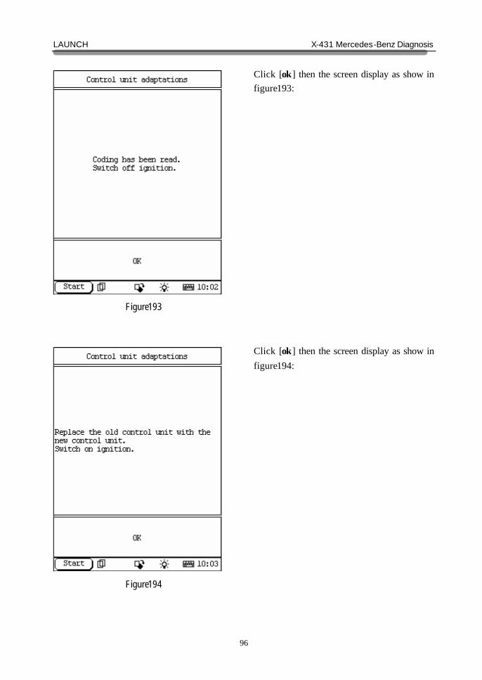
Figure193
Figure194
Click [ok] then the screen display as show in figure193: Click [ok] then the screen display as show in figure194:
LAUNCH X-431 Mercedes-Benz Diagnosis
97
Figure195
Figure196
Click [ok] then the screen display as show in figure195: Click [yes] then the screen display as show in figure196:
LAUNCH X-431 Mercedes-Benz Diagnosis
98
Figure197
Figure198
Click [ok] then the screen display as show in figure197: Click [ok] then the screen display as show in figure198:
LAUNCH X-431 Mercedes-Benz Diagnosis
99
Figure199
Figure200
Click [ok] then the screen display as show in figure199: Click [ok] then the screen display as show in figure200:
LAUNCH X-431 Mercedes-Benz Diagnosis
100
Figure201
Figure202
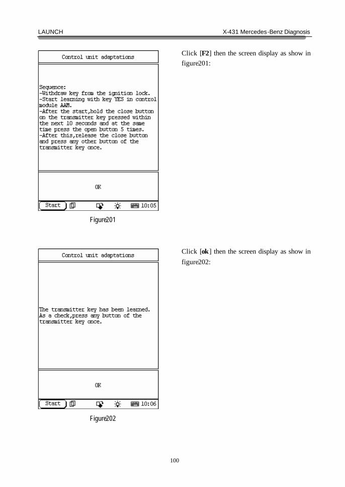
Click [F2] then the screen display as show in figure201: Click [ok] then the screen display as show in figure202:
LAUNCH X-431 Mercedes-Benz Diagnosis
101
Figure203
Figure204
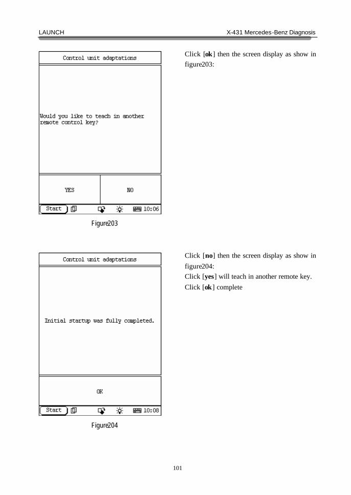
Click [ok] then the screen display as show in figure203: Click [no] then the screen display as show in figure204: Click [yes] will teach in another remote key. Click [ok] complete
LAUNCH X-431 Mercedes-Benz Diagnosis
102
Figure205
Figure206
Click [Read coding and change if necessary] that in figure190 then the screen display as show in figure205: Click [ok] then the screen display as show in figure206:
LAUNCH X-431 Mercedes-Benz Diagnosis
103
Figure207
Figure208
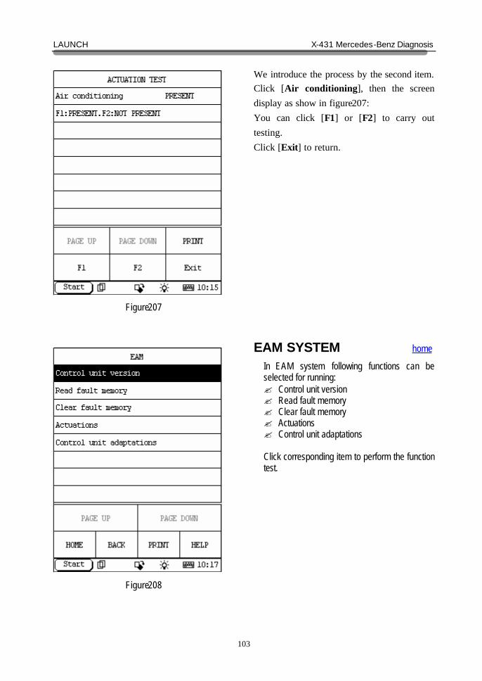
We introduce the process by the second item. Click [Air conditioning], then the screen display as show in figure207: You can click [F1] or [F2] to carry out testing. Click [Exit] to return.
EAM SYSTEM home In EAM system following functions can be selected for running: ? Control unit version ? Read fault memory ? Clear fault memory ? Actuations ? Control unit adaptations Click corresponding item to perform the function test.
LAUNCH X-431 Mercedes-Benz Diagnosis
104
Figure209
Figure210
Control Unit Version home
Click [Control unit version] that in the function menu. The screen will display the information about the control unit version of the test system, as shown in Figure209:
Read Fault Memory home
Click [READ FAULT MEMORY] in the function menu. X-431 starts to scan the fault code. The screen will display the result after the scanning is finished. Figure 210 shows an example. Note: ? The first part of the information is the
fault code; the second part is description of the fault code; the third part is the status of the fault code (there may be no third part for some fault code).
? If there is no fault code in the tested system, the screen will display message “No fault present”.
? After the test result is displayed, click [PRINT] to print out the test result.
Click [ok] to return to the function menu
LAUNCH X-431 Mercedes-Benz Diagnosis
105
Figure211
Figure212
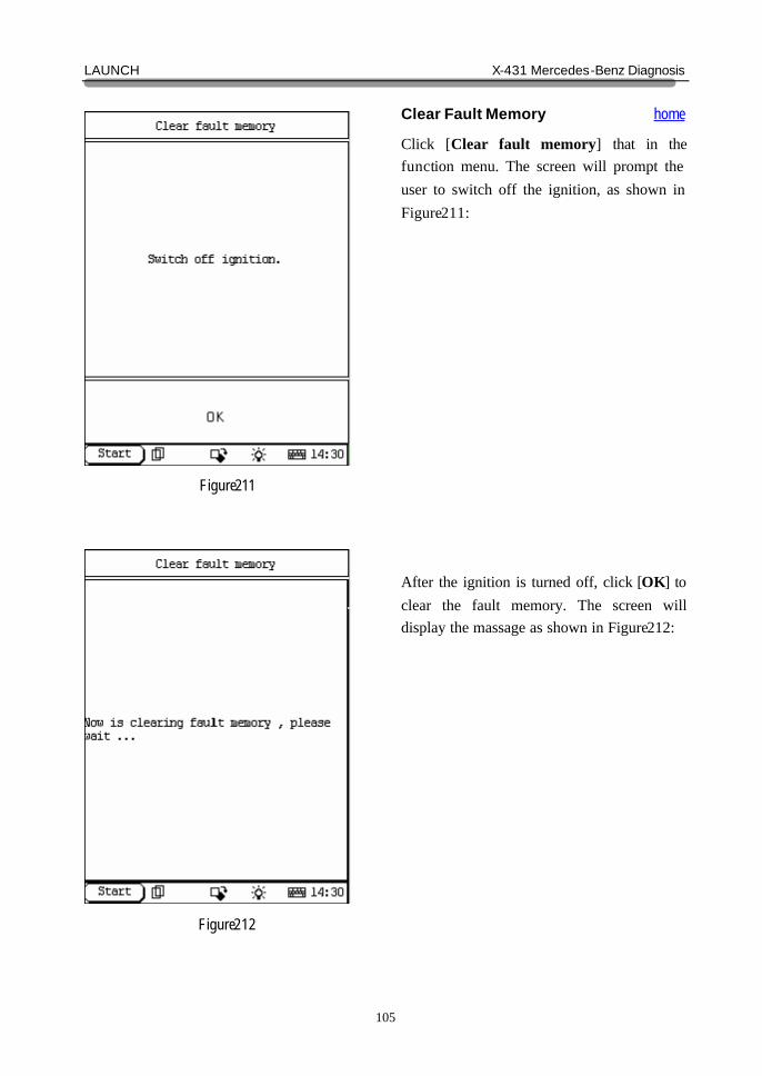
Clear Fault Memory home
Click [Clear fault memory] that in the function menu. The screen will prompt the user to switch off the ignition, as shown in Figure211: After the ignition is turned off, click [OK] to clear the fault memory. The screen will display the massage as shown in Figure212:
LAUNCH X-431 Mercedes-Benz Diagnosis
106
Figure213
Figure214
After the fault code is cleared, the screen will show the related message. Click [OK] to return to the function menu.
Actuations home
Click [Actuations] in the function menu. The screen will display a list of actuations, as shown in Figure214:
LAUNCH X-431 Mercedes-Benz Diagnosis
107
Figure215
Figure216
Select the actuations item, carry out testing according the hint the screen display. For the [automatic dimming mirror] example as show in figure215:
Control Unit Adaptations home
Warning! Do not perform this operation discretionarily; only the professional can do the control unit adaptations. Click [Control Unit Adaptations] in the function menu. The screen display will be as shown in Figure216:
LAUNCH X-431 Mercedes-Benz Diagnosis
108
Figure217
Figure218
Click [Initial startup with automatic takeover of settings of previous control unit] then the screen display as show in figure217: Click [yes] then the screen display as show in figure218:
LAUNCH X-431 Mercedes-Benz Diagnosis
109
Figure219
Figure220
Click [ok] then the screen display as show in figure219: Click [ok] then the screen display as show in figure220:
LAUNCH X-431 Mercedes-Benz Diagnosis
110
Figure221
Figure222
Click [yes] then the screen display as show in figure221: Click [no] then return. Click [yes] then the screen display as show in figure222: Click [cancel] will exit.
LAUNCH X-431 Mercedes-Benz Diagnosis
111
Figure223
Figure224
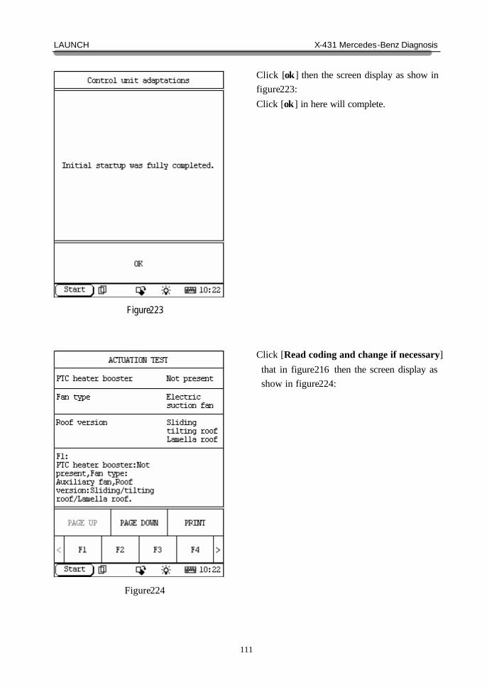
Click [ok] then the screen display as show in figure223: Click [ok] in here will complete. Click [Read coding and change if necessary] that in figure216 then the screen display as show in figure224:
LAUNCH X-431 Mercedes-Benz Diagnosis
112
Figure225
Figure226
Click [PAGE DOWN] to display more hint, carry out testing according the hint the screen display. As show in figure225:
D2B SYSTEM home In D2B system following functions can be selected for running: ? Control unit version ? Read fault memory ? Clear fault memory ? Control unit adaptations Click corresponding item to perform the function test.
LAUNCH X-431 Mercedes-Benz Diagnosis
113
Figure227
Figure228
Control Unit Version home
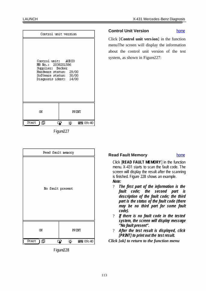
Click [Control unit vers ion] in the function menuThe screen will display the information about the control unit version of the test system, as shown in Figure227:
Read Fault Memory home
Click [READ FAULT MEMORY] in the function menu. X-431 starts to scan the fault code. The screen will display the result after the scanning is finished. Figure 228 shows an example. Note: ? The first part of the information is the
fault code; the second part is description of the fault code; the third part is the status of the fault code (there may be no third part for some fault code).
? If there is no fault code in the tested system, the screen will display message “No fault present”.
? After the test result is displayed, click [PRINT] to print out the test result.
Click [ok] to return to the function menu
LAUNCH X-431 Mercedes-Benz Diagnosis
114
Figure229
Figure230
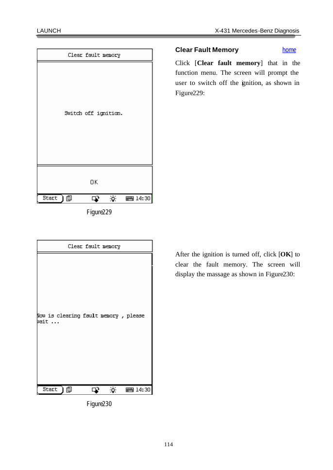
Clear Fault Memory home
Click [Clear fault memory] that in the function menu. The screen will prompt the user to switch off the ignition, as shown in Figure229: After the ignition is turned off, click [OK] to clear the fault memory. The screen will display the massage as shown in Figure230:
LAUNCH X-431 Mercedes-Benz Diagnosis
115
Figure231
Figure232
After the fault code is cleared, the screen will show the related message. Click [OK] to return to the function menu.
Control Unit Adaptations home
Warning! Do not perform this operation discretionarily; only the professional can do the control unit adaptations. Click [Control Unit Adaptations] in the function menu. The screen display will be as shown in Figure232:
LAUNCH X-431 Mercedes-Benz Diagnosis
116
Figure233
Figure234
Click [Activate radio code number] then the screen display as show in figure233: Click [ok] then the screen display as show in figure: Click [ok] in here to complete
LAUNCH X-431 Mercedes-Benz Diagnosis
117
Figure235
Figure236
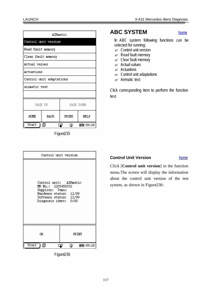
ABC SYSTEM home In ABC system following functions can be selected for running: ? Control unit version ? Read fault memory ? Clear fault memory ? Actual values ? Actuations ? Control unit adaptations ? Airmatic test
Click corresponding item to perform the function test
Control Unit Version home
Click [Control unit version] in the function menu.The screen will display the information about the control unit version of the test system, as shown in Figure236:
LAUNCH X-431 Mercedes-Benz Diagnosis
118
Figure237
Figure238
Read Fault Memory home
Click [READ FAULT MEMORY] in the function menu. X-431 starts to scan the fault code. The screen will display the result after the scanning is finished. Figure237 shows an example. Note: ? The first part of the information is the
fault code; the second part is description of the fault code; the third part is the status of the fault code (there may be no third part for some fault code).
? If there is no fault code in the tested system, the screen will display message “No fault present”.
? After the test result is displayed, click [PRINT] to print out the test result.
Click [ok] to return to the function menu
Clear Fault Memory home
Click [Clear fault memory] that in the function menu. The screen will prompt the user to switch off the ignition, as shown in Figure238:
LAUNCH X-431 Mercedes-Benz Diagnosis
119
Figure239
Figure240
After the ignition is turned off, click [OK] to clear the fault memory. The screen will display the massage as shown in Figure239:
After the fault code is cleared, the screen will show the related message. Click [OK] to return to the function menu.
LAUNCH X-431 Mercedes-Benz Diagnosis
120
Figure241
Figure242
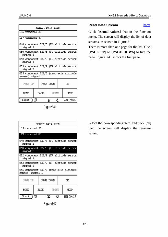
Read Data Stream home
Click [Actual values] that in the function menu. The screen will display the list of data streams, as shown in Figure 31 There is more than one page for the list. Click [PAGE UP] or [PAGE DOWN] to turn the page. Figure 241 shows the first page Select the corresponding item and click [ok] then the screen will display the real-time values.
LAUNCH X-431 Mercedes-Benz Diagnosis
121
Figure243
Figure244
Actuations home
Click [Actuations] in the function menu. The screen will display a list of actuations, as shown in Figure243:
Select the actuations item, for example [1.front ascend] then the screen display as show in figure: Click [START] then start testing. Click [EXIT] then return.
LAUNCH X-431 Mercedes-Benz Diagnosis
122
Figure245
Figure246
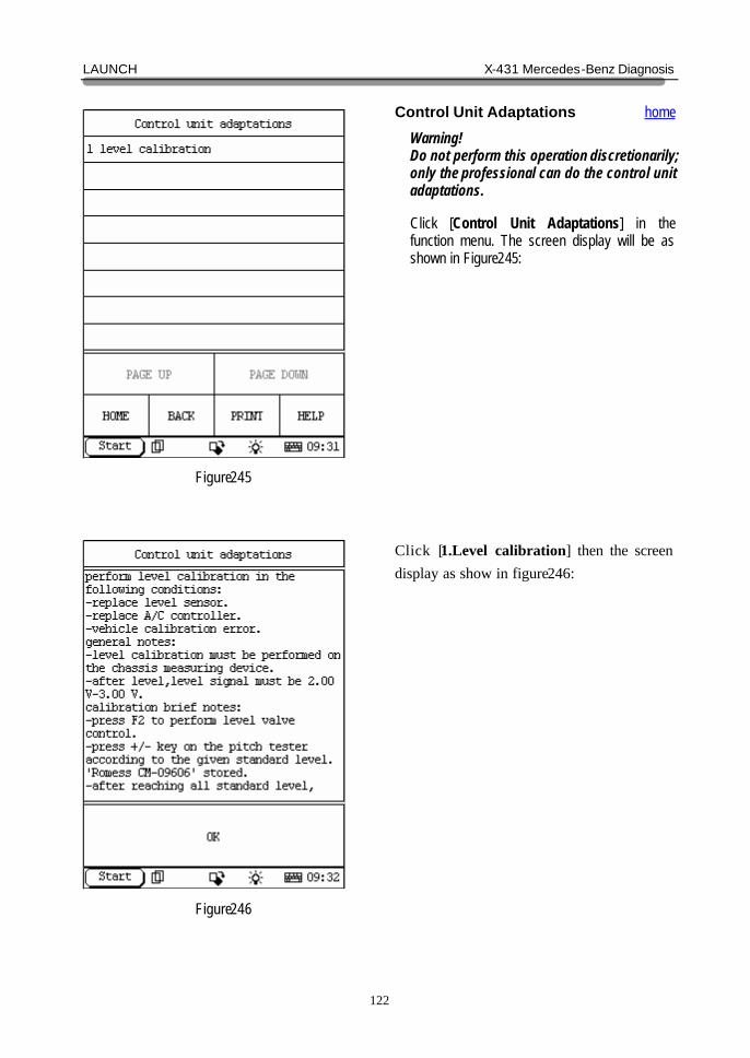
Control Unit Adaptations home
Warning! Do not perform this operation discretionarily; only the professional can do the control unit adaptations. Click [Control Unit Adaptations] in the function menu. The screen display will be as shown in Figure245:
Click [1.Level calibration] then the screen display as show in figure246:
LAUNCH X-431 Mercedes-Benz Diagnosis
123
Figure247
Figure248
Click [ok] then the screen display as show in figure247: Click [PADE DOWN] then the screen display as show in figure248: You can see more hint. Carry out testing according the hint the screen display.
LAUNCH X-431 Mercedes-Benz Diagnosis
124
Figure249
Figure250
For example, click [F2] then the screen display as show in figure249:
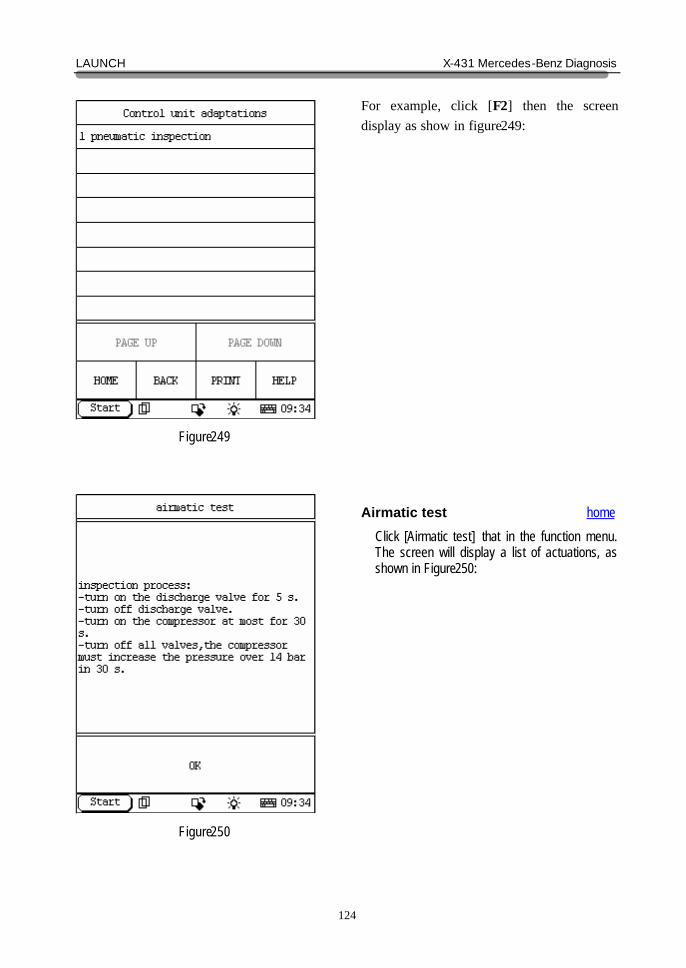
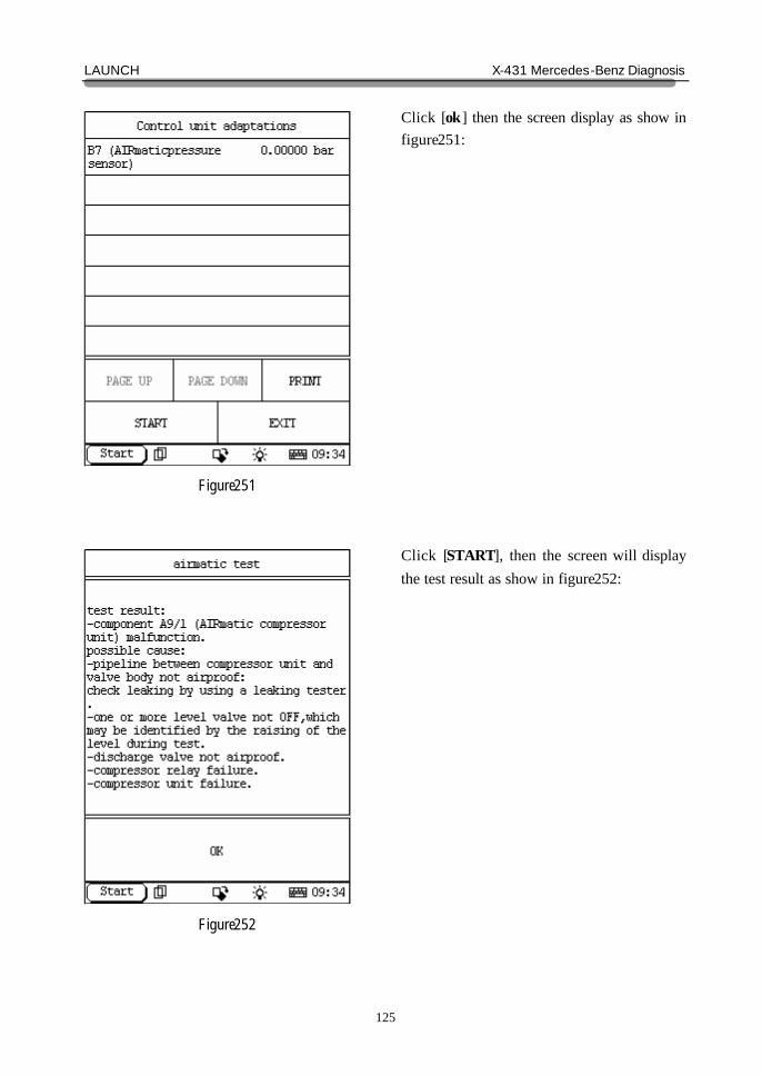
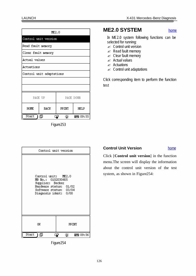
Airmatic test home
Click [Airmatic test] that in the function menu. The screen will display a list of actuations, as shown in Figure250:
LAUNCH X-431 Mercedes-Benz Diagnosis
125
Figure251
Figure252
Click [ok] then the screen display as show in figure251: Click [START], then the screen will display the test result as show in figure252:
LAUNCH X-431 Mercedes-Benz Diagnosis
126
Figure253
Figure254
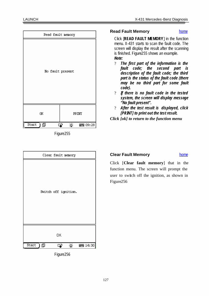
ME2.0 SYSTEM home In ME2.0 system following functions can be selected for running: ? Control unit version ? Read fault memory ? Clear fault memory ? Actual values ? Actuations ? Control unit adaptations
Click corresponding item to perform the function test
Control Unit Version home
Click [Control unit version] in the function menu.The screen will display the information about the control unit version of the test system, as shown in Figure254:
LAUNCH X-431 Mercedes-Benz Diagnosis
127
Figure255
Figure256
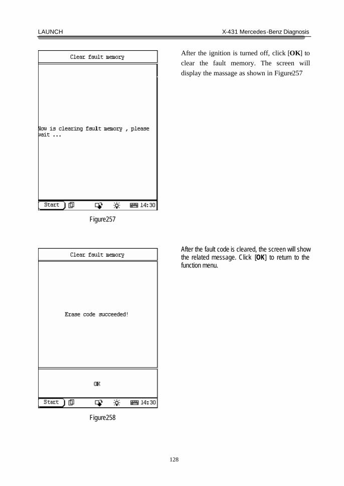
Read Fault Memory home
Click [READ FAULT MEMORY] in the function menu. X-431 starts to scan the fault code. The screen will display the result after the scanning is finished. Figure255 shows an example. Note: ? The first part of the information is the
fault code; the second part is description of the fault code; the third part is the status of the fault code (there may be no third part for some fault code).
? If there is no fault code in the tested system, the screen will display message “No fault present”.
? After the test result is displayed, click [PRINT] to print out the test result.
Click [ok] to return to the function menu
Clear Fault Memory home
Click [Clear fault memory] that in the function menu. The screen will prompt the user to switch off the ignition, as shown in Figure256:
LAUNCH X-431 Mercedes-Benz Diagnosis
128
Figure257
Figure258
After the ignition is turned off, click [OK] to clear the fault memory. The screen will display the massage as shown in Figure257:
After the fault code is cleared, the screen will show the related message. Click [OK] to return to the function menu.
LAUNCH X-431 Mercedes-Benz Diagnosis
129
Figure259
Figure260
Read Data Stream home
Click [Actual values] that in the function menu. The screen will display the list of data streams, as shown in Figure 31 There is more than one page for the list. Click [PAGE UP] or [PAGE DOWN] to turn the page. Figure 259 shows the first page Select the corresponding item.
LAUNCH X-431 Mercedes-Benz Diagnosis
130
Figure261
Figure262
Click [ok] then the screen will display the real-time values.
Actuations home
Click [Actuations] in the function menu. The screen will display as shown in Figure262:
LAUNCH X-431 Mercedes-Benz Diagnosis
131
Figure263
Figure264
Click [ok] then the screen display as show in figure263: Click [ok] then the screen will display a list of actuations as show in figure264:
LAUNCH X-431 Mercedes-Benz Diagnosis
132
Figure265
Figure266
Select the actuations item, for example [04 Throttle valves] then the screen display as show in figure265: Click [ok] then the screen will display a list of actuations as show in figure266: Click [OPEN] or [CLSD] start testing.
LAUNCH X-431 Mercedes-Benz Diagnosis
133
Figure267
Figure268
Control Unit Adaptations home
Warning! Do not perform this operation discretionarily; only the professional can do the control unit adaptations. Click [Control Unit Adaptations] in the function menu. The screen display will be as shown in Figure267:
Click [ok] then the screen display as show in figure268:
LAUNCH X-431 Mercedes-Benz Diagnosis
134
Figure269
Figure270
Click [1 Read or carry out coding] then the screen display as show in figure269: Click [YES] then the screen display as show in figure270:
LAUNCH X-431 Mercedes-Benz Diagnosis
135
Figure271
Figure272
Click [ok] then the screen display as show in figure271: Click [ok] then the screen display as show in figure272:
LAUNCH X-431 Mercedes-Benz Diagnosis
136
Figure273
Figure274
Click [ok] then the screen display as show in figure273: Click [ok] then the screen display as show in figure274:
LAUNCH X-431 Mercedes-Benz Diagnosis
137
Figure275
Figure276
Click [YES] then the screen will display corresponding hint Figure263 show a case. Click [OK] then return. Click [2 Erase coding] that in figure268 then the screen display as show in figure276:
LAUNCH X-431 Mercedes-Benz Diagnosis
138
Figure277
Figure278
Click [YES] then the screen display as show in figure277: Click [3 Idling speed selector lever P/N] that in figure268 then the screen display as show in figure278:
LAUNCH X-431 Mercedes-Benz Diagnosis
139
Figure279
Figure280
Click [OK] then the screen display as show in figure279: Click [OK] then the screen display as show in figure280:
LAUNCH X-431 Mercedes-Benz Diagnosis
140
Figure281
Figure282
Click [5 Self-adaptation] that in figure268 then the screen display as show in figure281: Click [OK] then the screen display as show in figure282:
LAUNCH X-431 Mercedes-Benz Diagnosis
141
Figure283
Figure284
Click [Original initialization] then the screen display as show in figure283: Click [YES] then the screen display as show in figure284:
LAUNCH X-431 Mercedes-Benz Diagnosis
142
Figure285
Figure286
Click [OK] then the screen display as show in figure285: Click [OK] then the screen display as show in figure286:
LAUNCH X-431 Mercedes-Benz Diagnosis
143
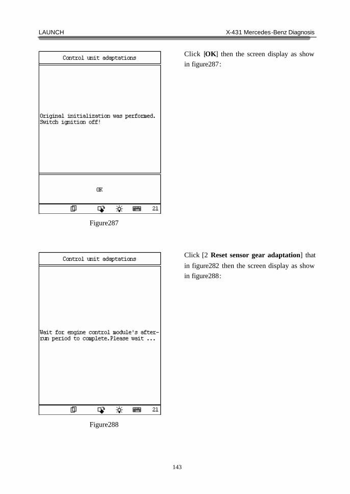
Figure287
Figure288
Click [OK] then the screen display as show in figure287: Click [2 Reset sensor gear adaptation] that in figure282 then the screen display as show in figure288:
LAUNCH X-431 Mercedes-Benz Diagnosis
144
Figure289
Figure290
after several seconds, the screen display as show in figure289: Click [OK] then the screen display as show in figure290:
LAUNCH X-431 Mercedes-Benz Diagnosis
145
Figure291
Figure292
Click [OK] then the screen display as show in figure291: Click [3 Adaptation data] that in figure282 then the screen display as show in figure292:
LAUNCH X-431 Mercedes-Benz Diagnosis
146
Figure293
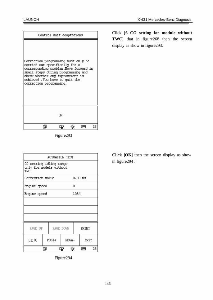
Figure294
Click [6 CO setting for module without TWC] that in figure268 then the screen display as show in figure293: Click [OK] then the screen display as show in figure294:
LAUNCH X-431 Mercedes-Benz Diagnosis
147
Figure295
Click [EXIT] then the screen display as show in figure295: Click [OK] will finish.