Departments of Petroleum and Mechanical Engineering Separation Technology Projects (TUSTP) JIP on Design and Performance of Compact Separators for Multiphase Production Systems 18 th Advisory Board Meeting May 20, 2003
Transcript
Departments of Petroleum and Mechanical Engineering
Separation Technology Projects(TUSTP)
JIP onDesign and Performance of
Compact Separators forMultiphase Production Systems
18th Advisory Board MeetingMay 20, 2003
TABLE OF CONTENTS
Page
Introductory Remarks (Shoham) 1-1
New DOE and NSF Proposals (Mohan) 2-1
DOE Project: Design and Performance of Multiphase Distribution Manifold (Bustamante) 3-1
DOE Project: StarCut Differential Dielectric Sensor–Experiments and Modeling (Xiang) 4-1
DOE Project: Horizontal Pipe Separator (HPS�) (Perez) 5-1
Foam Flow in GLCC� (Guzman) 6-1
DOE Project: Modeling Slug Dissipation in Helical Pipes (Di Matteo) 7-1
TU CoRE Project: Dispersion Characterization Rig (DCR) (Gomez) 8-1
Event Simulation and Diagnostics of GLCC Multiphase Metering System (Kumar) 9-1
Mechanistic Modeling and CFD Simulations of Oil-Water Dispersions
in Separation and Piping Components (Torres) 10-1
PhD Proposal: Intelligent Control of Compact Separation System (Sampath) 11-1
PhD Proposal: Interfacial Phenomena in Oil-Water Dispersions (Avila) 12-1
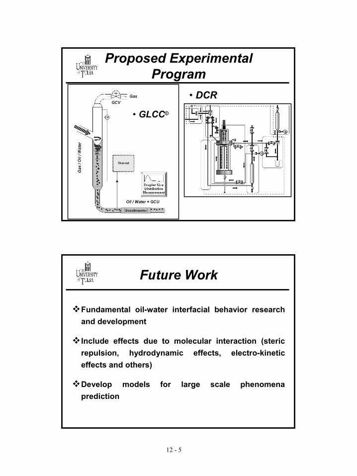
Evaluation of Oil-Water Flow through Different Piping Restrictions (Kuantaev) 13-1
APPENDICES
APPENDIX A: TUSTP Advisory Board Members
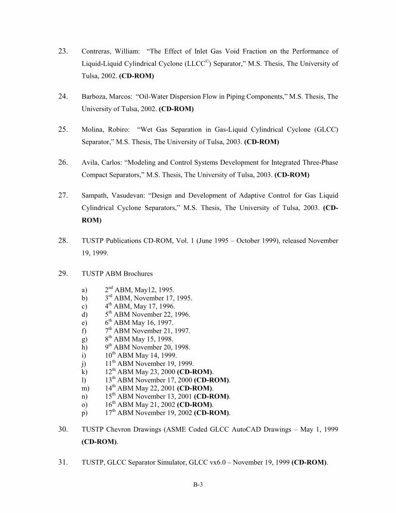
APPENDIX B: TUSTP Library
APPENDIX C: New DOE Proposal - Executive Summary
APPENDIX D: New NSF I/UCRC Proposal Summary
1 - 1
Departments of Petroleum and Mechanical Engineering
Separation Technology Projects(TUSTP)
JIP onDesign and Performance of
Compact Separators forMultiphase Production Systems
18th Advisory Board MeetingMay 19 and 20, 2003
Departments of Petroleum and Mechanical Engineering
Separation Technology Projects(TUSTP)
1 - 2
� Research Scope• oil/water/gas three-phase separation • suite of different compact separation units• compact separation systems• control strategies• flow conditioning• hydrodynamics of oil-water dispersion• dispersion and foam characterization
� Funding:• Additional DOE, NSF, TU-CoRE and OCAST
� Facilities:• Oil/water/gas state-of-the-art indoor facility• Gas/liquid outdoor facility • Dispersion Characterization Rig (DCR)• 12 different test sections
� Outdoor: Hydrodynamic GLCC�; Control GLCC�; Helical Pipe; Slug Damper
� Personnel Development:• 26 students graduated (6 PhD and 20 MS)• 2 visiting assistant professors/research associates• Currently: 11 graduate and 5 undergraduate
students• Consulting company established (MSI)
� Important Deliverables:• GLCC, LLHC, LLCC, and Slug Damper codes• “Sizing and performance predictions are at levels
unsurpassed by any other separation technology”� Technology Transfer and Field Applications:
• About 500 GLCC applications in the field. • GLCC has gone from “Technology of Last Resort”
to “Technology of First Choice” • Technology poised for exponential growth
� Academics:
• Total 46 papers, 23 in refereed journals
• GLCC introduced in undergraduate curriculum• Compact Separation Course will be offered in
Fall 2003 by Dr. Wang at graduate level
TUSTP
1 - 3
TUSTP Activities
� TUSTP Activities:
� Slug Damper vx 1.0 code released today
� GLCC vx7.6 code released today
� Two Emulsion Short Courses scheduled for industry:- Drs. Jean Louis Salager and Johan Sjoblom
� “Dispersion Characterization Rig” (DCR) ordered following funding approval from ChevronTexaco TU-CoRE
� GLCC skid from Humble being shipped to TUSTP
� NSF-I/UCRC (Pre-proposal) funded, DOE andNSF-I/UCRC (Full) proposals submitted
� Dr. R. Mohan on sabbatical in 2003; Received 2003 College of E&NS outstanding researcher award
� TUSTP received Best Paper award in the DeepwaterChallenge Session of the 5th International PetroleumConference and Exhibition (Petrotech, India, 2003)
� Drs. O. Shoham and R. Mohan visited Shell (Holland) in January 2003 for GLCC� workshop
� 12:00 Lunch
� 1:00 Business Meeting
� 3:30 Tour of Facilities
� 6:30 TUSTP Reception/Dinner
Agenda, 5/19/2003
1 - 4
� 8:00 Continental Breakfast
� 8:30 Introductory Remarks (Shoham)
� 8:55 New DOE and NSF Proposals (Mohan)
� 9:20 Multiphase Distribution Manifold (Bustamante)
� Develop improved individual components to ensure simple, compact, cost-effective, and high-efficient separation of clean streams of gas, oil, water and solids. Develop the second generation CMSS integrating these components.
� Adapt the developed compact separation systems for Floating Production Storage and Offloading (FPSO) systems and subsequently for subsea applications.
Fundamental CMSS Configuration Using Field Tested Components
LLHCGLCC
LLHC
Wet Gas Scrubber
CleanGas
Clean OilFor Transport
Three-Phase
Mixture
FWKOLLHC
Clean WaterFor Disposal
SSUSolids
2 - 3
Second Generation CMSS Configuration with New Components
GLCC
LLHC
Wet Gas Scrubber
CleanGas
Clean OilFor Transport
Three-Phase
Mixture
Clean WaterFor Disposal
SSUSolids
Ann. Film Extractor
LLCC
HPS
� Industry/University Cooperative Research Center
� Focus on Multiphase Transport Phenomena� 25 faculty: Engineering (Chemical,
Mechanical, Petroleum), Physics, Polymer Science, Applied Math
� $30k annual membership fee leverages more than $600K in annual research
� NSF contributes $150K annually ($50K per university)
� Univ. of Tulsa, Michigan State University, University of Akron
National Science FoundationI/UCRC
2 - 4
Mission Statement
� I/UCRC-MTP will support the combined research and education mission of the National Science Foundation in the area of CMTP by bringing together experimental, theoretical, and computational experts from industry and academia in order to
1) conduct pre-competitive leading edge research related to emerging and traditional technologies that involve multiphase phenomena
2) develop next generation MTP models3) develop next generation CMTP design tools and 4) develop innovative methods to effectively train
� Research emphasis is on pre-competitive technologies
� NSF will form the center for 5 years with a possible extension for another 5 years
2 - 5
Research Focus
� Research is conducted in 5 areas: Multiphase Fluids, Porous Media, Mixing and Reactions, Separations, and Turbulence
� Faculty, Graduate students and undergrad students work in multi-disciplinary teams
� IAB meets bi-annually to review and select projects that are funded
Multiphase Fluids
� Develop improved models and computational methods
� Predict microstructure of complex fluids in confined flows and free jets
� Composite materials with nanofibers and nanoparticles
� Strategies for manufacturing polymer matrix composites
2 - 6
Multiphase Porous Media
� Computational methods for fluid flow and heat transfer through porous media
� Development of high efficiency filters, gas phase coalescers, oil/water separators
� Evaluate natural and forced convective heat transfer in porous structures such as in fuel cells or in sediment around buried sub-sea pipelines
Multiphase Mixing and Reactions
�Computational methods to track motion of an interface between immiscible fluids
�Analysis of liquid jet breakup, mixing of oil and water, coalescence of liquid drops on fibers
�Analysis of stability of liquid/gas interfaces in molding, fuel sprays, interfacial reactions, and oil-water separations in hydrocyclone separators
2 - 7
Multiphase Separations
�Computational methods for predicting the separation of oil-water-gas mixtures
�Analysis of re-suspension of sand in oil-water-gas flows
�Evaluate sub-sea and surface oil-water-gas pipe and separator designs
�Evaluate the strategic placement and performance of sand separators
Multiphase Turbulence
� Methods to predict the mean field velocity and mean field pressure distributions
� Develop turbulence models for flows with strong streamline curvature
� Analysis of hydrocyclone separators, mixing of liquid and gases in furnace tubes, and liquid/gas sprays
2 - 8
Intellectual Property
� IP is owned by the universities� Members have 30 days to review papers for
proprietary reasons� All technologies are available to members for
internal use� Royalty free license granted to members sharing
in patent costs� If only one member wants license, member may
request exclusive royalty bearing license
Key Participants The University of Tulsa
University of Tulsa:
Dr. Ram S. Mohan, Mechanical EngineeringDr. Ovadia Shoham, Petroleum EngineeringDr. Luis Gomez, Petroleum EngineeringDr. Shoubo Wang, Petroleum EngineeringDr. Keith Wisecarver, Chemical EngineeringDr. Brenton McLaury, Mechanical EngineeringDr. Leslie Thompson, Petroleum Engineering
2 - 9
Key ParticipantsMSU and University of Akron
Michigan State University:Dr. Charles Petty, Chemical EngineeringDr. Andre Benard, Mechanical EngineeringDr. Farhad Jaberi, Mechanical EngineeringDr. A.Y. Lee, Material Science
University of Akron:Dr. George Chase, Chemical EngineeringDr. Ed Evans, Chemical EngineeringDr. G. W. Young, MathematicsDr. R. Ramsier, Physics
Target Industry Participants
AEA Technology (CFX) Ford Motor Company Bechtel General Motors CD-Adapco Los Alamos National LabCETCO HoneywellChevronTexaco NATCO Daimler-Chrysler PetrobrasDELPHI Timken Research Corp. DOE VisteoneSpin Technologies Williams InternationalExxonmobil FLUENT
2 - 10
See more information at websites
�NSF Operational Proposalwww.egr.msu.edu/mtp
�NSF CRCD Projectwww.vu.msu.edu/preview/eng-mtp
Letter of Intent
�Endorse forming the center�Endorse proposed research agenda,
indicate research has potential impact on industry
�State company intends to join the center �Signed by responsible authorized person�Contact Ram Mohan for more information
3 - 1
TUSTP 2003
By Angel Bustamante
May 20, 2003
DOE Project:Design and Performance of
Multiphase Distribution Manifold
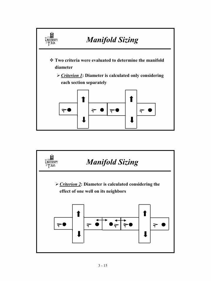
� Introduction
� Objectives
� Experimental Program
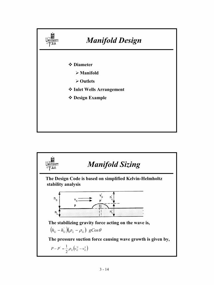
� Manifold Design
� Future work
Topics
3 - 2
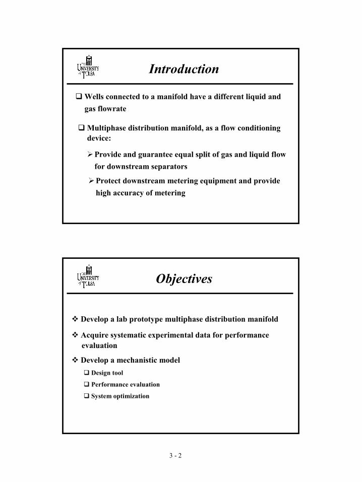
Introduction
� Wells connected to a manifold have a different liquid and gas flowrate
�Provide and guarantee equal split of gas and liquid flow for downstream separators
�Protect downstream metering equipment and provide high accuracy of metering
� Multiphase distribution manifold, as a flow conditioning device:
Objectives
� Develop a lab prototype multiphase distribution manifold
� Acquire systematic experimental data for performanceevaluation
� Develop a mechanistic model � Design tool
� Performance evaluation
� System optimization
3 - 3
Experimental Program
� Experimental Facility
� Test Matrix
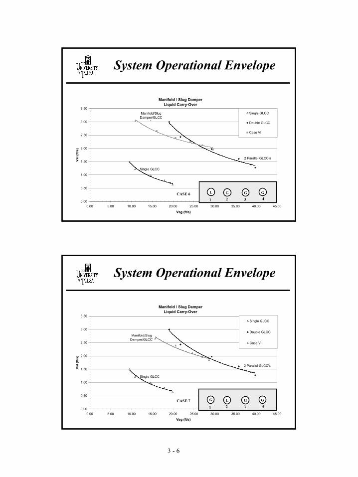
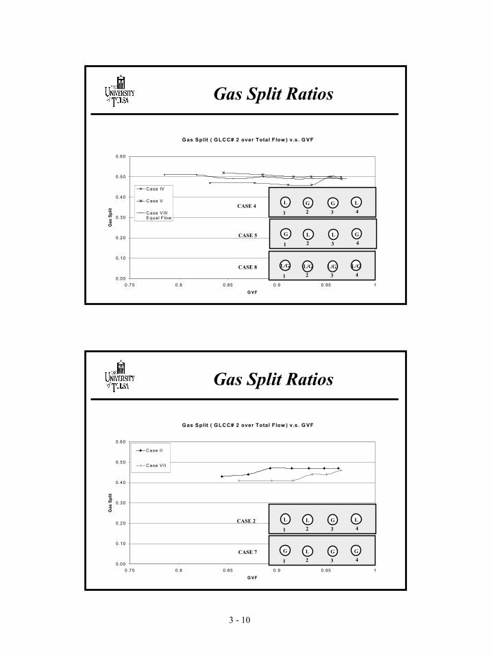
� Results
�System Operational Envelope
�Manifold Operational Envelope
�Liquid and Gas Split Ratios
�Manifold Resistance Coefficient (Kl)
�Transient Performance
Experimental Facility
Liquid Outletsto Micromotion
GLCC # 1
Gas Outlets
Vortex Meter
Vortex Meter
Distribution Manifold
Slug Damper
Rotameters
Liquid line
Gas line
GLCC # 2
3 - 4
Flow Configurations
1 2 3 4L GL LCASE 1
1 2 3 4
L LL GCASE 2
1 2 3 4L GL GCASE 3
1 2 3 4L LG GCASE 4
1 2 3 4G GL LCASE 5
1 2 3 4
L GG GCASE 6
1 2 3 4G GL GCASE 7
Test Matrix
Vsg: 10.5 fts/s to 30.5 ft/s, Vsl: 1.0 ft/s to 2.75 ft/s
v Study the behavior of oil-water mixtures in horizontal pipes
v Develop a mechanistic model that predicts separation efficiency for given fluids, geometry and flow rates
v Compare/refine model with data obtained in this study and from literature
v Study effects of using manifolds to install multiple separators in parallel
Objectives
v Objectives
v Physical phenomena in HPS
vModeling approach
v Experimental program
v Conclusions - Future Work
Topics
5 - 3
Zone 1 Zone 2
Zone 3
Zone 4
OilOil with Water dropletsPacked water droplets in oilPacked oil droplets in water
Water with Oil droplets
Water
Physical phenomena in HPS
Inlet Direction of flow Outlets
Oil-Water mixture enters HPS, with droplet distribution function of processes upstream. Some mixing can occur at inlet (Zone 1)Inside HPS the velocity decreases, turbulence decreases (laminar flow might be reached), settling and coalescence are promoted (Zone 2), layers begin to developUp to 6 layers can develop (Zone 3):- Pure Oil- Oil with water droplets- Packed water droplets in oil- Packed oil droplets in water- Water with oil droplets- Pure water
Eventually steady state is reached (Zone 4)
Physical phenomena in HPS
5 - 4
v Regimes of operation in HPS
v Laminar flow is desirable as it promotes segregationv Oil is more likely to flow to be in laminar flow conditions
due to higher viscosityv So, desirable flow regimes are:
- Laminar Oil Flow - Laminar Water Flow- Laminar Oil Flow - Turbulent Water Flow
v Study flow in HPS requires:- Steady state conditions: max segregation- Transient conditions: how long it will take
- Shoham-Taitel (1984, gas-liquid)- Elseth et al. (2000, VOF method)- Gao et al. (2003, VOF method)
1D mechanistic approach leads to simple solutions, so it will be used as an initial approach
Modeling approach
5 - 6
vProposed model:
v1- 1D stratified flow pattern model is applied for given fluids and flow rates. If flow is stable, flow characteristics are given by the model
v2- If flow is unstable, following procedure applies:- An amount of the more viscous phase is assumed to
flow to the less viscous phase- For this new flow rate, properties are calculated for
mixture, segregated flow is assumed, and stability is checked. Migration stops when stability is reached
- No convergence means non segregated flow
Modeling approach
vPreliminary resultsModel tested against experimental data (Shi et al. (2000)) v Test conditions:
- Oil properties: 3 cp, 800 kg/m3
- Water properties: 1 cp, 1100 kg/m3
- Pipe: 0.1 m ID, 18m long- Mixture velocity: 0.4 to 3 m/s- Water Cut: 0.2, 0.4, 0.6, 0.8
v Trallero (1995) model used, Sheltering Factor assumed 0v Increased interfacial friction factor as mixing and waves form
at the interface
Modeling approach
5 - 7
vResults: Pure oil and water layer thickness
Modeling approach
40% WC
00.10.20.30.40.50.60.70.80.9
1
0 0.5 1 1.5
Mixture Velocity m/s
hl/D
Experimental Oil-Mix level
Experimental Mix-Water Layer
Model Oil-Mix layer
Model Mix-WaterLayer
60% WC
00.10.20.30.40.50.60.70.80.9
1
0 0.5 1 1.5
Mixture velocity m/s
hl/D
Experimental Oil-Mix level
Experimental Mix-Water layer
Model Oil-MixLayer
Model Mix-WaterLayer
v Objectives
v Physical phenomena in HPS
vModeling approach
v Experimental program
v Conclusions - Future work
Topics
5 - 8
Test Section
Experimental program
v Calibration:
vLevel: Pipe centerline leveled in +-3/32” range from horizontal
vLevel sensors: For operating conditions, level meters are able to detect continuous interface with error of 3/32”
Experimental program
5 - 9
v Typical level meter signal at interface
Experimental program
Sensor 2 signal function of dimensionless height
0
0.10.20.3
0.40.5
0.60.70.8
0.91
0 1 2 3 4 5
Voltage
hl/
D
Test 1Test 2Test 3Test 4Top of sensorBottom of sensor
Sensor stem gap:
7/32”
vPitot / Isokinetic sampling probe
Previous works: - Kohr, Mendes-Tatsis and Hewitt (1996)- Vedapuri, Bessette and Jepson (1997)- Shi, Cai and Jepson (1999)- Cai, Gopal and Jepson (2000)
Experimental program
5 - 10
vPitot / Isokinetic sampling probe
vCharacteristics - ID= 3/16”- OD= 11/32”- Operating dP: 0 to 1” H2O, accuracy dP 0.15%- Range of operation:
. Min. velocity: 0.06 m/s (error 10% )
. Max. velocity : 0.7 m/s (error 0.073% )
Experimental program
v Photo of assembled probe:
Base
Pitot
Pressure outlets
Sampling outlet
Experimental program
5 - 11
v Pitot / Isokinetic sampling probe in place
Experimental program
v Pitot / Isokinetic sampling probe- Calibration results for single phase
Experimental program
150 lbs/min oil
00.050.1
0.150.2
0.250.3
0.350.4
0.45
0 0.5 1 1.5
Distance from centerline (inches)
Vel
ocity
(m
/s)
1.71875
1.46875
1.21875
0.96875
0.71875
0.46875
0.21875
0.03125
Theoretical
Distance from wall 200 lbs/min water
0
0.05
0.1
0.15
0.2
0.25
0.3
0 0.5 1 1.5
Distance from centerline (inches)
Vel
ocity
(m/s
)
1.75
1.5
1.25
1
0.75
0.5
0.25
0
Theoretical
Distance from wall
5 - 12
vPitot / Isokinetic sampling probe- Problems when measuring oil-water flow. After flushing
with oil, water flood pitot, capillarity causes oscillations in dP while flooding
- Improved with wider pressure taps. dP values will be taken at initial plateau, before flooding occurs.
Experimental program
Signal from dP, at 0.75" from bottom
0
1
2
3
4
5
6
0 20 40 60 80
Time (1/2 sec)
Vol
tage Test 3
Test 2Test 1
Plateau Flooding
v Calibration results: Effects of oil-water flowv Pitot filled with oil, mixture flowing Vsl=0.6 m/s, WC 60%
Experimental program
Velocity Profile: Vmix=0.6 m/s, WC 60%
00.1
0.20.30.40.50.60.70.80.9
1
0 0.2 0.4 0.6 0.8 1
Velocity (m/s)
hl/D Velocity Profile
5 - 13
v Objectives
v Physical Phenomena in HPS
vModeling approach
v Experimental program
v Conclusions/ Future Work
Topics
v Initial model for all flow conditions is proposed. Actual model underpredicts thickness of pure fluid zones
vModel requires higher interfacial shear stress when mixing layers are present
v Pitot measurements for low velocities are affected by capillarity in pitot pressure taps Measurement criterion was adapted for this condition
Conclusions/Future Work
5 - 14
vMeasurement of velocity profiles for experimental matrix
vMeasurement of hold up for experimental matrixv Hold up/Interfacial friction factor adjustment with
Experimental ResultsDissipation Length vs Initial Slug Length
Dh = 1.95 m
1
10
10 100 1000lSi/dp
l DIS
S (tu
rn)
Vm = 1, 1.05, 1.1 m/s
10.110.05 5.05
10.05.0
Total Dissipation Before Turn No.1
1.5
Vm = 5 to 10.1 m/sPartial Dissipation (PD)
Total Dissipation (TD)
Label points = Mixture Velocity (m/s)
7-9
Slide # 7-17
Experimental ResultsDissipation Length vs Initial Slug Length
Dh = 1.33 m
1
10
10 100 1000lSi/dp
l DIS
S (tu
rn)
Vm = 1, 1.05, 1.1 m/s
1.5
10.010.05
5.05 5.05.1
Total Dissipation (TD)
Total Dissipation Before Turn No.1
Vm = 5 to 10.1 m/s Partial Dissipation (PD)
Label points = Mixture Velocity ( m/s)
Slide # 7-18
Experimental ResultsDissipation Length vs Initial Slug Length
Dh = 0.74 m
1
10
10 100 1000lSi/dp
l DIS
S (tu
rn)
Vm = 1, 1.05, 1.1 m/s
1.5
10.0
10.05
5.05
5.0
10.110.5
Total Dissipation (TD)
Total Dissipation Before Turn No.1
Partial Dissipation (PD)
1.05
5.1
5.5
Label points = Mixture Velocity (m/s)
7-10
Slide # 7-19
� One-Dimensional Flow
� Initial Conditions: Stable Stratified Flow
� Not Normal Slug Flow
� Neglect Secondary Flow
� Neglect Radial Pressure Gradient
� Constant vSL and vSG
Mechanistic ModelAssumptions
Slide # 7-20
� Gravitational Force Mechanism:�Low Superficial Gas Velocities�Larger Helical Diameter�Larger Equivalent Dissipation Length
� Centrifugal Force Mechanism:�High Superficial Gas Velocities�Smaller Helical Diameter�Smaller Equivalent Dissipation Length
� Slug Front Stability Mechanism:�Low Slug Velocities
Mechanistic ModelDissipation Mechanisms
7-11
Slide # 7-21
Mechanistic ModelGeneral Approach
vF1
Approach:
� Slug Tracking: Track Front and Tail of Slug
lS
vT1
vT2vS
�
vF2
Slide # 7-22
Mechanistic ModelNomenclature
vF1Nomenclature:vT1,T2 : Velocity of the Slug Front/Tail InterfacesvS : Velocity of the Liquid SlugvF1,F2 : Velocity of the Film Ahead/Behind the SlugHF1,F2: Liquid Holdup in the corresponding FilmHS : Liquid Holdup in the Liquid Slug� : Angle of Inclination respect to horizontallS : Length of the Liquid Slug Body
� Process Hazard Analysis for GLCC System� Develop a Diagnostic System for Possible Hazard Events
� Simulate Various Problems Encountered in Field Operation (start up, shut down, hardware failure, severe slugging, system upset, etc.) for GLCC�
� Identify the Critical Issues
� Make Specific Recommendations
9-3
� LCV Failed at North Campus-TUSTP� LCV Failed at Minas LOSF Area-1� Level Control Failure Due to Improper
Installation/Selection of dp Transducer
Problems Reported
Diagnostics
� LCV Failure (TUSTP)
� Moisture in the Instrumentation Air Line
� Loss of Data
� LCV Failure (Minas)
� Don’t Know the Reason of LCV Failure
� Cause of Oil Relief to Environment (Control configuration)
� Level Control Failure
� Non-usage of Isolation Diaphragm for the dp Cell
9-4
� Answer is YES!!!!� We Should have Process Hazard Analysis for GLCC
System!
Can there be more Probable Events?
Process Hazard Analysis of GLCC
Hazard and Operability Study
What-If Check List
Preliminary hazard Analysis
Failure Modes and Effect Analysis
Human Reliability Analysis
Cause – Consequence Analysis
Fault Tree
Event Tree
PHA
9-5
Hazard and Operability Study-HazOps
Hazard and Operability Study-HazOps
9-6
� Nodes of the System� Liquid Control Valve� Gas Control Valve� Single Phase Meters� GLCC Upper & Lower Sections� Gas and Liquid Legs� Control System� Differential Pressure Sensor� Level Transducer
Identification of Sections of GLCC
� A consistent Strategy is considered for the risk criteria employed in a risk assessment, in order to minimize risk levels, as far as is reasonably possible
� Risk Levels Concerned� Risk to Personnel (safety)� Risk to Environment� Risk to the Public� Financial Risk
Risk Acceptance Criteria - PHA
9-7
Risk Matrix
33333IV
33221
III
32211
II
32111I
EDCBA
�Probability DefinitionsA - Possibility of Repeated
Incidents B - Possibility of Isolated IncidentsC - Possibility of Occurring
SometimeD - Not Likely to OccurE - Practically Impossible
� Consequence Definition(Personnel)I- Fatalities II – Serious Injury to PersonIII – Medical Treatment for
PersonnelVI - Minor impact on Personnel,
First aid only
Definition of Probability and Consequence
9-8
� Need for a Diagnostic System� Notification of the Specific Failure� Check if Sub System Working Fine� Safety
Diagnostics System for GLCC
Probable Events of Malfunctioning of Sub System
� LCV Failure� No Signal from LCV � Action of LCV is as Expected
� GCV Failure� No Signal from GCV� Action of GCV as Expected
� Pressure in Pneumatic Line is High/ Low� Level Shoot-Up in GLCC – Might Upset the Gas System if
Connected to the Gas Leg� No Signal from Controller and � Probable Failures Related to Sensors, Transducers
9-9
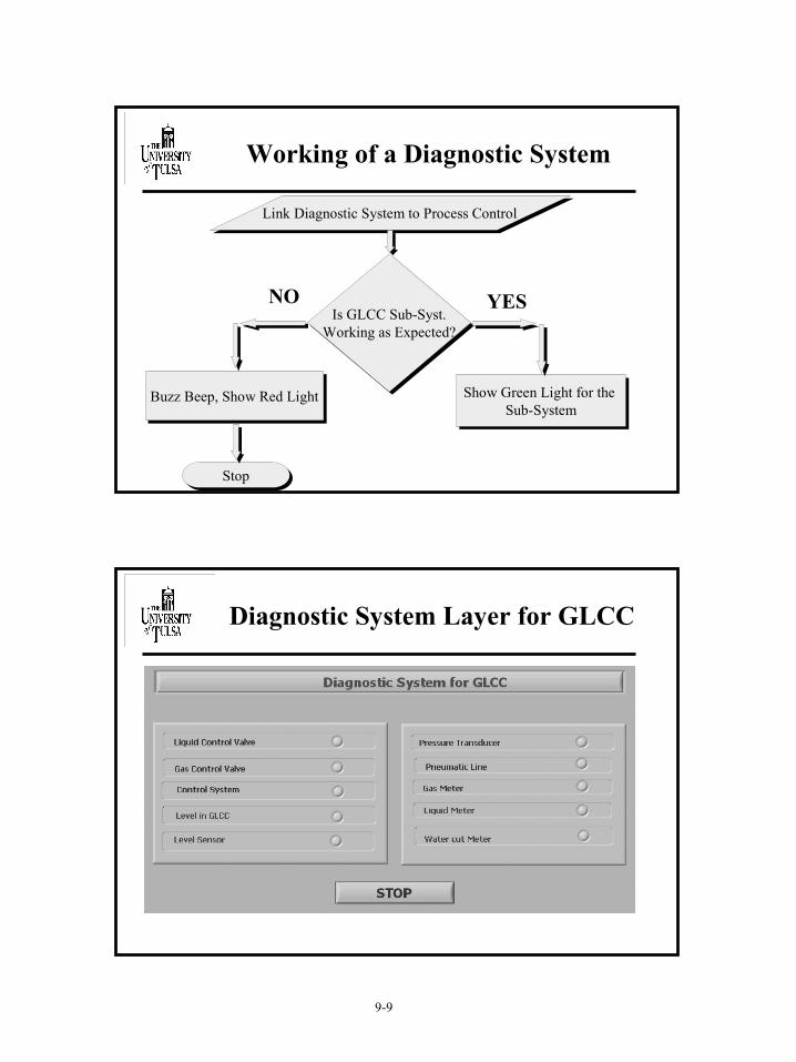
Working of a Diagnostic System
Link Diagnostic System to Process Control
Is GLCC Sub-Syst.Working as Expected?
Show Green Light for the Sub-System
Buzz Beep, Show Red Light
Stop
NO YES
Diagnostic System Layer for GLCC
9-10
Diagnostics of LCV
� Check for Signal from LCV� If signal not present – Buzz a Beep� If Signal Detected – Check if LCV Opens and Closes in the
Right Direction as per the Liquid Level in GLCC� If Yes! - Show Green Light on Diagnostic Board� If No! -Red Light, Buzz a Beep , Stop the System and
Display Related Error Message
View of a Diagnostic Board
�LCV Working Fine �LCV Malfunctioning
9-11
Lab View –Checks LCV
Event Simulation
� Simulate the Field Conditions on Lab View:� Start-up Conditions
� Shut-down Conditions
� Hardware Failure
� Combine Simulator with Diagnostic System
9-12
Start-up
� Simulate Start up Flow Conditions:� Flow Increases from Zero to a very high Quantity
� Nature of Behavior of Control Valves to this Variation of Flow in Short Time
� Nature of Change in Liquid Level in GLCC
� Response of Diagnostic System to Sudden Rise in Liquid Level in GLCC
Shut-Down
� Simulate Shut Down Flow Conditions:� Flow Decreases from a very high value to zero
� Nature of Behavior of Control Valves to this Variation of Flow in Short Time
9-13
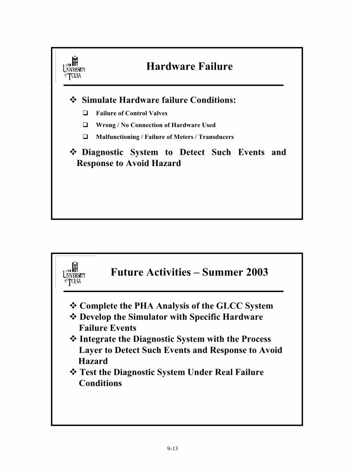
Hardware Failure
� Simulate Hardware failure Conditions:� Failure of Control Valves
� Wrong / No Connection of Hardware Used
� Malfunctioning / Failure of Meters / Transducers
� Diagnostic System to Detect Such Events and Response to Avoid Hazard
Future Activities – Summer 2003
� Complete the PHA Analysis of the GLCC System� Develop the Simulator with Specific Hardware
Failure Events� Integrate the Diagnostic System with the Process
Layer to Detect Such Events and Response to AvoidHazard
� Test the Diagnostic System Under Real FailureConditions
10 - 1
Mechanistic Modeling and CFD Simulations of Oil-Water Dispersions
in Separation Components
TUSTP 2003
byCarlos F. Torres
May 20, 2003
Background
Objectives
Particle Tracking Model
Preliminary Results
Universal Dispersion Model
Topics
10 - 2
Knowledge of particle motion and phase distribution will enhance performance evaluation of separation equipment
TUSTP has used the Eulerian-Lagrangian technique to design and analyze performance of separation devices such as GLCC, LLCC and LLHC
Existing models carry out simulations considering mainly the following forces acting on a particle: drag and buoyancy
Additionally, these models assume particle local equilibrium
Background
The general objectives of this study are to develop models capable of characterizing hydrodynamics of multiphase dispersion flow in separations and piping components
Initially, study focuses on dilute and dense dispersed flow
Develop a mechanistic model for calculating droplet motion, considering the different acting forces
Determine dispersed phase void fraction
Validate and extend the three way coupling approach proposed by Gomez 2001
Objectives
10 - 3
General approach
Simplified approach
Future improvements
Particle Tracking Model
Particle Tracking:General Approach
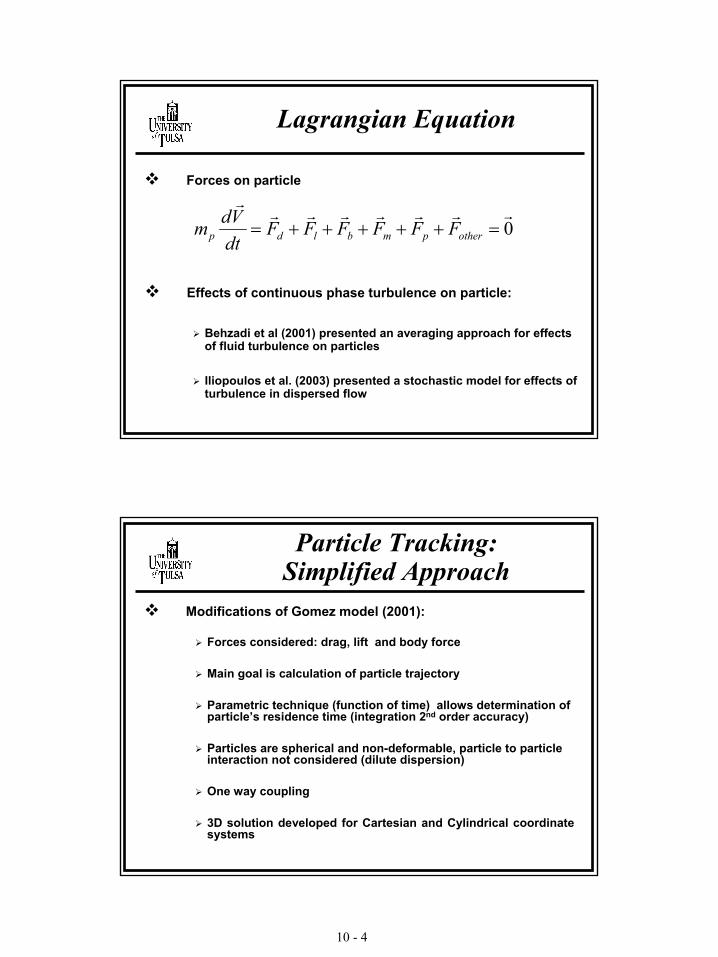
Gomez 2001 presented a new Eulerian – Lagrangian mechanistic model:
Local equilibrium assumed for dispersed phase
Forces used: drag, lift, body force, added mass and pressure gradient
Model is one way coupling between continuous and dispersed phase, considering variation of interfacial area
10 - 4
Lagrangian Equation
0rrrrrrr
r
=+++++= otherpmbldp FFFFFFdtVdm
Forces on particle
Effects of continuous phase turbulence on particle:
Behzadi et al (2001) presented an averaging approach for effects of fluid turbulence on particles
Iliopoulos et al. (2003) presented a stochastic model for effects of turbulence in dispersed flow
Particle Tracking:Simplified Approach
Modifications of Gomez model (2001):
Forces considered: drag, lift and body force
Main goal is calculation of particle trajectory
Parametric technique (function of time) allows determination ofparticle’s residence time (integration 2nd order accuracy)
Particles are spherical and non-deformable, particle to particle interaction not considered (dilute dispersion)
One way coupling
3D solution developed for Cartesian and Cylindrical coordinate systems
10 - 5
Modified Gomez Model
Particle Position
bld FFFrrrr
++=0
∫∫∫+
+
+
+
+
+ +=+=+=1ti
tizii
1ti
tiyii
1ti
tixii dtVzzdtVyydtVxx 111
Forces on Particle
Particle Tracking:Future Improvements
Extend model capability to include:
Added mass force
Pressure gradient force (hydrodynamic)
Fluid turbulent effects
Particle transients effect
Develop mechanistic model for estimation of void fraction using stochastic approach
Explore limits of dilute flow assumption, and extend to dense flow
10 - 6
Preliminary Results
Particle Tracking in Pipe Flow
Particle Tracking in Conventional Separators
Particle Tracking: Pipe Flow
Mixing Length Velocity Profile
0 0.2 0.4 0.6 0.8 10
0.1
0.2
0.3
0.4
0.5
0.6
0.7
0.8
0.9
1
Laufer, J. 1951, (Re = 40000)U+ Inner LayerU+ Outher Layer
Velocityat the inlet = 2 m/sat the interphase = 0.2 m/s
Diameterat the inlet = 0.1 mat the outlet = 0.1 m
Vesselliquid level = 1 m
Reynolds Numberat the inlet = 5666.7in the vessel = 5666.7
Fluent 12 Mar 2003 title
Particle Tracking:Conventional Separators
Particle Tracking: Conventional Separators
Particle Residence Time = 2.63 s
Particle Density = 2500 kg/m3
Particle Diameter = 500 micron
10 - 9
Particle Tracking: Conventional Separators
X
Y
0 1 2 3 40
0.5
1
1.5
2
2.5
Frame 001 12 Mar 2003 Particle Tracking
Particle Residence Time = 2.362 s
Particle Density = 2500 kg/m3
Particle Diameter = 500 micron
Universal Dispersion Model
Gomez Model (2001)
The Eulerian field is known (average velocities, turbulent kinetic energy and energy dissipation)
Solve Lagrangian field using the proposed equation, to calculate slip velocity within flow fieldSolve diffusion equation using slip velocity information, to predict void fraction distributionCalculate bubble or droplet diameter using Eulerian turbulent quantities and void fraction distributionRepeat non-linear process until convergence is reached
10 - 10
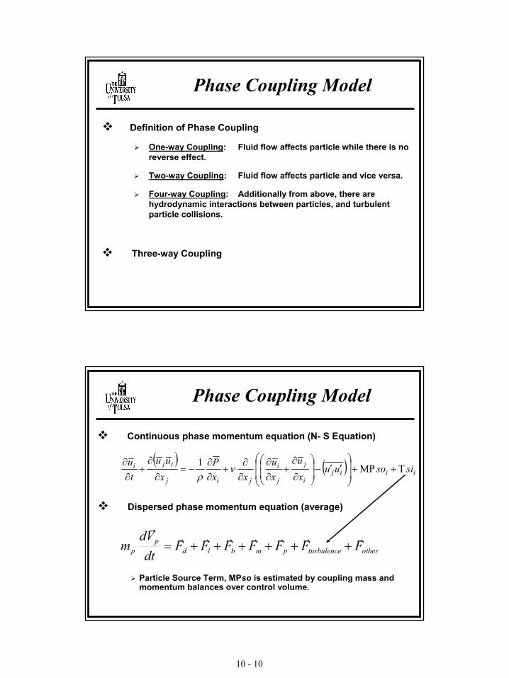
Phase Coupling Model
Definition of Phase Coupling
One-way Coupling: Fluid flow affects particle while there is no reverse effect.
Two-way Coupling: Fluid flow affects particle and vice versa.
Four-way Coupling: Additionally from above, there are hydrodynamic interactions between particles, and turbulent particle collisions.
Three-way Coupling
Phase Coupling Model
( ) ( ) iiiji
j
j
i
jij
iji sisouuxu
xu
xxP
xuu
tu
TMP1++
′′−
∂
∂+
∂∂
∂∂
+∂∂
−=∂
∂+
∂∂
νρ
Dispersed phase momentum equation (average)
Continuous phase momentum equation (N- S Equation)
otherturbulencepmbldp
p FFFFFFFdtVd
mrrrrrrr
r
++++++=
Particle Source Term, MPso is estimated by coupling mass and momentum balances over control volume.
10 - 11
Two-way Coupling: Solution Scheme
PSI – Cell technique, Crowe et al. (1977)
Huber &Sommerfelt (1997).
Air continuousPhase. θ = 0o, d = 80 mm,V = 24 m/s,
Dispersed phaseρd = 2500 kg/m3
dp = 40 micron
Model Potential
LLCCDispersion of Oil in Water
with Water Layer at the BottomVm = 0.6 m/s W.C = 67%
10 - 12
Questions
? ? ? ?
11-1
TUSTP 2003
byVasudevan Sampath
May 20, 2003
Intelligent Control of
Compact Separation System
OverviewObjectivesLiterature ReviewCompact Separation SystemReview of Control System DevelopmentFuzzy Logic SystemArtificial Neural Network SystemFuture Plans
11-2
ObjectivesConduct a detailed study on advanced control systems like fuzzy logic, neural network etc. and study their suitability for compact separation system.
Develop an intelligent control strategy for compact separation system and conduct dynamic simulation and experimental investigation on the developed strategy.
Literature Review
Control System Studies:Wang (2000) : Dynamic Simulation, Experimental Investigation and Control System Design of GLCC
Dorf & Bishop (1998): Modern Control SystemsGrimble (1994): Robust Industrial Control Friedland (1996): Advanced Control System Design
11-3
Fuzzy Logic and Neural Networks:McNeill and Thro (1994): Fuzzy LogicLeondes (1999): Fuzzy Theory Systems –Techniques and Applications Terano, Asai and Sugeno (1994): Applied Fuzzy SystemsPassino and Yurkovich (1998): Fuzzy ControlReznik (1997): Fuzzy Controllers
Literature Review
Compact Separation System 1
Clean
Water Rich
Oil Rich
GLLCC (3-phase)
Pipe Type Separator
GLCC (Scrubber)
LC
PC
LC
WCC
WCC FC
Pump
Clean OilOil
Water Rich
Oil Rich
GLLCC (3-phase)
Pipe Type Separator
GLCC (Scrubber)
ManifoldSlug Damper
LCLC
PCPCClean GasClean GasLCLC
WCCWCC
WCCWCC
Hydrocyclones
LLCCPRC
PRC
Hydrocyclones
LLCC
FCFC PRCPDC
PDC
PumpPump
Clean Water
LC-Level Control
PC-Pressure Control
WCC-Water cut Control
FC-Feed Control
PDC-Press. Diff. Control
11-4
Compact Separation System 2
PCPC
LCLC
Clean Gas
LCLC
Hydrocyclones
LLCCPRC
PRC
Hydrocyclones
LLCC
FCWC PRCPDC
PDC
PumpPump
WCCWCCGLCC (Scrubber) Pipe Type
Separator
Clean OilOil
ManifoldSlug Damper
GLCC
Liquid Stream
Gas Stream
Clean Water
LC-Level Control
PC-Pressure Control
WCC-Water cut Control
FC-Feed Control
PDC-Press. Diff. Control
No.
APPLICATION CLASSES
Pass
ive
Con
trol
Sys
tem
Liqu
id L
evel
Con
trol
with
LC
V O
nly
Liqu
id L
evel
Con
trol
with
GC
V O
nly
Hyb
rid L
CV
and
GC
V Le
vel C
ontr
ol
Pres
sure
Con
trol
with
GC
V
Liqu
id L
evel
Con
trol
with
LC
V an
d Pr
essu
re C
ontr
ol w
ith G
CV
Flow
Rat
e C
ontr
ol w
ith L
CV
and
GC
V
Pred
ictiv
e C
ontr
ol o
f GLC
C
usin
g Sl
ug D
etec
tion
GLC
C O
ptim
al a
nd A
dapt
ive
Con
trol
- M
ovin
g Se
t poi
nt
Wat
ercu
t Con
trol
Sys
tem
GVF
Con
trol
Sys
tem
Rob
ust C
ontr
ol W
ith
Gai
n Sc
hedu
ling
Mod
ern
Con
trol
- Fu
zzy
Logi
c C
ontr
ol
Inte
llige
nt C
ontr
ol -
Art
ifici
al N
eura
l Net
wor
k
Dow
nStr
eam
ON
/OFF
Pu
mp
Con
trol
GLC
C D
ual I
nlet
Con
trol
GLC
C V
aria
ble
Are
a In
let C
ontr
ol
1 Remote Powerless GLCC Operation X2 Remote GLCC Operation With Power X X X X X X X X X X X3 Well Testing (Recombined Flow) X X X X X X X X X X X X4 Bulk Separation (Separator Stand Alone) X X X X X X X X X X5 DownStream Surge Tank Control X X6 Separation of Wet Gas (raw Gas Lift) X X X X X X X X X X X
7Separation of Low-Medium GOR (Liquid Dominated) X X X X X X X X
8 Separator subjected to Severe Slugging X X X X X
9Integrated Separation systems - 2 Stage GLCCs X X X X X X X X
10 GLCC with Liquid Hydrocyclones X X X X X X X X X11 GLCC Upstream of pumps X X X X X X X X12 GLCC with Conventional Separators X X X X X X X X X X X13 Subsea Application X X X X X X X X X14 Downhole Applications X X X X X
15Non-Petroleum Application - Liquid Metering X X X X X
16Non-Petroleum Application - Gas Metering X X X X X X
17 FREE-WATER Knockout with LLCC X X X X X X X X X18 GLCC/LLCC Integrated System Control X X X X X X X X X X X X X X X19 GLCC for Environmental Applications X X X X X X
CONTROL STRATEGIES
11-5
Control System Development Stages
1st Stage: Frequency –response design methods for scalar systems by Nyquist, Bode
2nd Stage: The state-space approach to optimal control and filtering theory
3rd Stage: Multivariable systems by frequency-domain design methods (MIMO)
Adaptive Control – Estimates parameters and calculates the control accordingly. Involves online design computations, difficult to implement.
Robust Control – This allows for uncertainty in the design of a fixed controller, thus, producing a robust scheme, which is insensitive to parameter variations or disturbances. H∞ robust control philosophy provides optimal approach to improve robustness of a controlled system.
11-6
Limitations of Conventional Controllers
Plant non-linearity: Nonlinear models are computationally intensive and have complex stability problems.
Plant uncertainty: A plant does not have accurate models due to uncertainty and lack of perfect knowledge.
Uncertainty in measurements: Uncertain measurements do not necessarily have stochastic noise models.
Temporal behavior: Plants, Controllers, environments and their constraints vary with time. Time delays are difficult to model.
Fuzzy Logic Control
Crisp man Fuzzy man
How are you going to park a car ?
It’s eeeeassy……!
Just move slowly back and avoid any obstacles.
You have to switch to reverse, then push an accelerator for 3 minutes and 46 seconds and keep a speed of 15mph and move 5m back after that try………..
11-7
Benefits of Fuzzy Logic Controller
Can cover much wider range of operating conditions than PID and can operate with noise and disturbance.
Developing a fuzzy logic controller is cheaper than developing a model-based controller.
Fuzzy controllers are customizable. Since it is easier to understand and modify their rules.
Simultaneous use of large number of relatively simple processors, instead of using very powerful central processor.
Parallel computation enables short response times for tasks that involve real time simultaneous processing of several signals.
Each processor is an adaptable non linear device.
11-11
Neuro Fuzzy Systems
Neural Networks are good at recognizing patterns, not good at explaining how they reach that decision
Fuzzy logic are good at explaining their decision but they cannot automatically acquire the rules they use to make those decisions
Central hybrid system which can combine the benefits of both areused for intelligent systems
Complex domain like process control applications require such hybrid systems to perform the required tasks intelligently
In theory neural network and fuzzy systems are equivalent in that they are convertible, yet in practice each has its own advantages anddisadvantages
Applications
Fuzzy Logic and Neural Network applications to compact separation system:
Dedicated control system for each component, like GLCC or LLCC
Sensor fusion – improvement in reliability and robustness of sensors
Supervisory control – intelligent control system with diagnostics capabilities.
11-12
Future Plans
1. Develop dedicated control systems for each component using neural network or adaptive control system.
2. Develop sensor fusion modules using neural networks to improve the quality of measured signal.
3. Develop intelligent supervisory control system for overall control, monitoring and diagnostics of the process.
12 - 1
TUSTP 2003
Carlos Avila
May 20, 2003
DOE Project:
Interfacial Phenomena in Oil - Water Dispersions
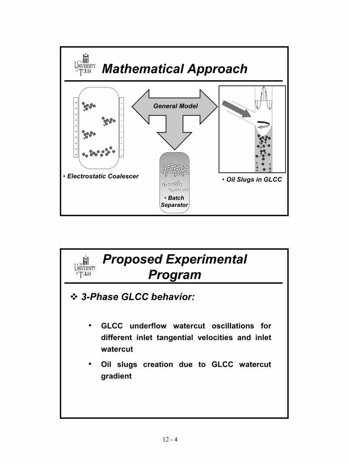
�Introduction�Objectives�Modeling Approach�Proposed Experimental Program�Future Work
Overview
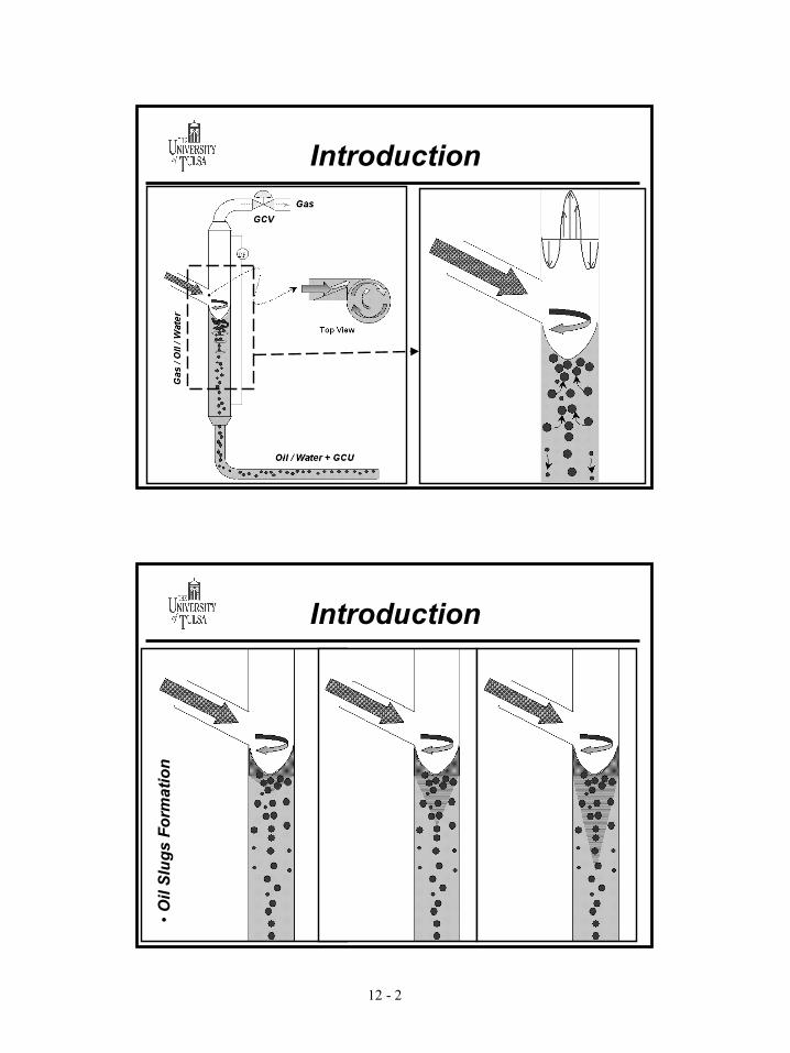
12 - 2
Introduction
Introduction
•Oil
Slug
s Fo
rmat
ion
12 - 3
Objectives
�Study fundamental oil-water interfacial phenomena (small-scale). Based on fundamental phenomena, develop models capable of predicting oil-water dispersion flow behavior (large-scale)
� Include studies on coalescence and break-up, segregation and droplet size distribution
�Validate developed models against current applications measurements
- Separation time less for flow through circular geometry as compared to rectangular geometry
- Pressure drop almost the same for both geometries
13-10
Conclusions
�Venturi
- Separation time less for venturi geometry as compared to rectangular channel
- Venturi exhibits less pressure drop than rectangular channel
Future Work
�More data needs to be acquired for higher pressure drop
�More studies needed to understand effect of different restriction geometries on droplet breakup/coalescence
�Improve instrumentations (Laser/Fiber Optic)
� Develop model for prediction of droplet size distribution through piping restrictions
APPENDIX A
TUSTP Advisory Board Members
A-1
TUSTP ADVISORY BOARD MEMBERS 2002/2003
Gene Kouba, Ph.D. Sr. Staff Research Scientist Advanced Production Tech. CHEVRONTEXACO Room 4107c 2811 Hayes Rd. Houston, TX 77082 Ph.: 281-596-2485 Fax: 281-596-2620 or 3009 e-mail: [email protected] www.chevrontexaco.com Jack Marrelli, Ph.D. Research Associate Production & Facility Optimization CHEVRONTEXACO Room #4141 2811 Hayes Road Houston, TX 77082-6696 Ph.: 281-596-2604 Fax: 281-596-2150 Cell: 713-826-9619 (7AM to 7PM) [email protected] www.chevrontexaco.com Ing. Horacio Gamboa Florez Jefe Tecnologias Complementarias Edelmira Afanador ECOPETROL Instituto Colombiano Del Petroleo Centro De Investigacion Y Desarrollo Autopista Bucaramanga Piedecuesta Km. 7, Santander A.A.4185 Bucaramanga, COLOMBIA Ph.: 011-57-76-445-420 x 7201 Fax: 011-57-76-445-444 Edelmira/Secretary: 011-57-76-740-226/264 e-mail: [email protected] e-mail: [email protected] www.ecopetrol.com.co
Joey Raskie Applications Specialist Coriolis Oil & Gas EMERSON PROCESS MANAGEMENT Micro Motion, Inc. 9720 Old Katy Road Houston, TX 77055 Ph.: 713-827-3356 Fax: 713-827-4360 [email protected] Denman Cloudt G. Joel Rodger, P.E. Manager of Metering Systems eProduction Solutions 10801 Hammerly, Suite 232 Houston, TX 77043 Ph.: 713-461-7995 Fax: 713-461-2675 Mobile: 832-755-2055 e-mail: [email protected][email protected] www.eproductionsolutions.com John Lievois Ph.D. P.E. eProduction Solutions, Inc. Ph.: 713-461-7995 Cell: 281-851-3603 Fax: 713-461-2675 e-mail: [email protected] Emil J. Klein Jim Bennett Gas and Facilities Division EXXONMOBIL UPSTREAM RESEARCH COMPANY P.O. Box 2189 Houston, TX 77252-2189 Ph.: 713-431-6233 (EK) Ph.: 713-431-7811 (JB) Fax: 713-431-6387 [email protected][email protected]
A-2
Ted Frankiewicz Vice President Liquid Process Solutions NATCO Group-US Brookhollow Central 111 2950 N. Loop West, 7th Floor Houston, TX 77092 Ph.: 713-685-8012 Fax: 713-975-9611 e-mail: [email protected] www.natcogroup.com/index2.html Mike Brown Senior Development Engineer Gary Sams Director, R&D NATCO-Group 10910 E. 55th Place Tulsa, OK 74146 Ph.: 918-660-7151 (GS) Ph.: 918-660-7152 (MB) Fax: 918-622-8058 e-mail: [email protected] e-mail: [email protected] www.natcogroup.com/index2.html A.K. Sah Deputy General Manager (P) Anand Gupta Superintending Engineer (P) Vineet Singhal Superintending Engineer (P) OIL AND NATURAL GAS CORPORATION LTD. (ONGC) IOGPT/ONGC ONGC Complex, Phase II Panvel, Raigad, Maharastra- 410221 INDIA Ph.: 91-(22) 7451148 (office) Fax: 91-(22) 7451690 e-mail: [email protected] e-mail: [email protected] e-mail: [email protected] www.ongcindia.com Jose Luis Trallero, Ph.D. E&P Technology Leader Dtto. Punta de Mata Exploration & Production PDVSA/INTEVEP Los Teques, Edo. Miranda Apdo 76343 Caracas 1070A
VENEZUELA Ph.: 011-58-2-908-6775 Fax: 011-58-2-908-7818 e-mail: [email protected] www.pdvsa.pdv.com Faustino Fuentes-Nucamendi, Ph.D. Gerencia de Sistemas de Produccion Subdireccion do Tecnologia y Desarrollo Profesional PEMEX EXPLORACION Y PRODUCCION Primer Piso, Edif. Piramide Av. Adolfo Ruiz Cortinez 1202 Villahermosa, Tabasco, 86030 MEXICO Ph.: 52-93-101-765 Fax: 52-93-10-18-89 e-mail: [email protected] Margarita Avila (Adm. Sec.) www.pemex.com Robert Smith, CEO SYSTEMS MEASUREMENT SERVICES (SMS) INC. 7000 Meany Ave. Bakersfield, CA 93308 Ph.: 661-589-7686 800-588-7686 Fax: 661-589-6883 e-mail:[email protected] www.systemsmeasurement.com Emile Leporcher TOTALFINAELF Centre de Recherche Jean Feger Avenue Larribau Pau, 64018 FRANCE e-mail: [email protected] Chris Roger TotalFinaElf Services, Inc. Research Center AtoFina 900 First Avenue King of Prussia, PA 19406 e-mail: [email protected] Contacts: [email protected][email protected]
A-3
[email protected][email protected][email protected][email protected] www.totalfinaelf.com/ho/en/index.html [email protected] Rick Todd Underbalanced Drilling Services, R&D WEATHERFORD INTERNATIONAL 11909 Spencer Road FM 529 Houston, TX 77041 Ph.: 713-983-5323 Fax: 713-983-5061 Mobile: 832-566-2576 Paul West Project Manager James L. Barnes Project Manager Rhonda Lindsey Senior Project Manager NETL/DOE Williams Center Tower One One West Third St., Suite 1400 Tulsa, OK 74103 Ph.: (PW) 918-699-2035 Ph.: (JB) 918-699-2076 Ph.: (RL) 918-699-2037 Fax: 918-699-2005 e-mail: [email protected] e-mail: [email protected] e-mail: [email protected]
A-4
TUSTP FACULTY AND STAFF Ovadia Shoham, Ph.D. Professor of Petroleum Engineering Director, TUSTP L109 KEH, The University of Tulsa 600 South College Avenue Tulsa, OK 74104-3189. USA Ph.: 918-631-3255 Fax: 918-631-2059 e-mail: [email protected] Ram S. Mohan, Ph.D. Associate Professor of Mechanical Engineering Associate Director, TUSTP L169 KEH, The University of Tulsa 600 South College Avenue Tulsa, OK 74104-3189. USA Ph.: 918- 631-2075 Fax: 918-631-2397 e-mail: [email protected] Luis Gomez, Ph.D. Visiting Assistant Professor Department of Petroleum Engineering Research Associate, TUSTP The University of Tulsa 600 South College Avenue Tulsa, OK 74104-3189. USA Ph.: 918- 631-2972 Fax: 918- 631-2059 e-mail: [email protected] Shoubo Wang, Ph.D. Visiting Assistant Professor Department of Petroleum Engineering Research Associate, TUSTP The University of Tulsa 600 South College Avenue Tulsa, OK 74104-3189. USA Ph.: 918-631-3041 Fax: 918-631-2059 e-mail: [email protected]
Judy Teal Administrative Assistant, TUSTP L111 KEH, The University of Tulsa 600 South College Avenue Tulsa, OK 74104-3189. USA Ph.: 918-631-2048 Fax: 918-631-2059 e-mail: [email protected]
A-5
PROSPECTIVE MEMBERS/FRIENDS K.T. Liu General Manager ACCUFLOW, INC. 3566 Dartmouth Lane Rowland Heights, CA 91748 Ph.: 562-691-5343 Fax: 562-691-5643 e-mail: [email protected] Jeffery P. Henning, M.S.(ChE) Project Manager, CFD Consulting Services AEA TECHNOLOGY 2000 Oxford Drive, Suite 610 Bethel Park, PA 15102 Ph.: 412-833-4820 Fax: 412-833-4580 e-mail: [email protected] www.aeat.com/cfx Shauna L. Wilson Senior Production Engineer Thermal Recovery Business Unit AEC OIL & GAS 3900, 421 – 7th Avenue S.W. Calgary, Alberta, Canada T2P 4K9 Ph.: 403-298-2855 Fax: 403-231-3697 Cell: 403-813-9525 e-mail: [email protected] www.aec.ca Michael O. Bridges Chief Engineer ANADARKO 1201 Lake Robbins drive The Woodlands, TX 77380 P.O. Box 1330, Houston, TX 77251-1330 Ph.: 832-636-3287 Fax: 832-636-8209 e-mail: [email protected] Andy Bennett BP Exploration, Deepwater Technology Unit, 1st Floor, Compass Point, 79-87 Kingston Road, Staines, Middlesex, TW18 1DY, UK Ph.: 44-1932-774816
Fax: 44-1932-774833 e-mail: [email protected] Donald D. Uphold, Ph.D. Senior Facilities Engineer, NFDT CALTEX PT Caltex Pacific Indonesia Minas 28885 Riau, Indonesia Ph.: (0761) 99-3155 Fax: (0761) 99-3440, 99-1226 e-mail: [email protected] Charles Britton Senior Staff Engineer CEESI Colorado Eng. Experiment Station, Inc. 54053 WCR 37 Nunn, CO 80648 Ph.: 970-897-2711 Fax: 970-897-2710 e-mail: cbritton@ceesi,com www.ceesi.com Robert (Bob) Chin President CDS SEPARATION TECHNOLOGIES 1500 S. Dairy Ashford, #441 Houston, TX 77077 Ph.: 281-589-8325 Fax: 281-589-8393 Cell: 281-788-6948 e-mail: [email protected] www.cds-separation.com Joe W. Westmoreland CHEVRONTEXACO Energy Research and Technology Co. Safety Engineer 4800 Fournace Place, Room 320L BOB Bellaire, TX 77401 Ph.: 713-432-6528 Cell: 832-794-0427 Fax: 713-432-2234 [email protected]
A-6
Mike Choi Senior Staff Engineer Infrastructure Structure Technology CONOCO, INC. Dubai, 2092 Post Office Box 2197 Houston, TX 77252-2197 Ph.: 281-293-1207 Fax: 281-293-2158 e-mail: [email protected] Paul Gillis, Research Leader Fluid Mechanics and Mixing Group DOW CHEMICALS 2301 N. Brazosport Blvd, B-1225 Freeport, TX 77541 Ph.: 409-238-1384 Fax: 409-238-0401 e-mail: [email protected] Bambang N. Gyat Director ENERKON ENGINEERS AND CONSTRUCTORS PT. Erraenersi Konstruksindo Ciladak Apartment, Ground Floor JL. T.B. Simatupang, Jakarta 12430 Ph.: 62-21-750 4963 Ext 105-115 Fax: 62-21-765 4984 e-mail: [email protected] Martin Tallett Principal ENSYS YOCUM INC. P.O. Box 2320 Flemington, NJ 08822 Ph.: 908-788-7332 Fax: 908-782-3768 e-mail: [email protected] Barbara Hutchings, Director Ahmad H. Haidari Strategic Partnerships FLUENT INC. 10 Cavendish Court Lebanon, NH 03766 Ph.: 603-643-2600 x 312 Fax: 603- 643-3967 e-mail: [email protected] (Barbara) e-mail: [email protected] (Ahmad) www.fluent.com
Daniel R. Sweet Director Business Development South THE FOXBORO COMPANY P.O. Box 597 Cypress, TX 77410 Ph.: 281-655-4999 Fax: 281-655-7109 Cell: 281-684-7557 e-mail: [email protected] www.foxboro.com Robbie Lansagan The Foxboro Company Ph.: 281-599-7832 832-794-3430 Miguel Gazzaneo Invensys Process Systems, Inc. THE FOXBORO COMPANY 10707 Haddington Dr. Houston, TX 77043 Ph.: 713-722-5371 Fax: 713-722-5753 e-mail: [email protected] Ferhat Metin Erdal Engineering Specialist/Project Engineer INTEC ENGINEERING, INC. 15600 JFK Boulevard Ninth Floor Houston, TX 77032 Ph.: 281- 925-2435 Fax: 281-925-2379 e-mail: [email protected] www.intec-hou.com Mark Hoyack Vice President, Industrial Division KREBS ENGINEERS 5505 West Gillette Road Tucson, AZ 85743 Ph.: 520-744-8200 Fax: 520-744-8300 e-mail: [email protected] Hank Rawlins, P.E. Technology Manager Jo Jernsletten Ove F. Jahnsen KVAERNER PROCESS SYSTEMS US 7909 Parkwood Circle Drive
A-7
6th Floor Houston, TX 77036 Ph.: 713- 271-7086 (HR) Ph.: 713- 369-5344 (JJ) Fax: 713- 271-7091 (HR) Fax: 713- 685-5838 (JJ) e-mail: [email protected] e-mail: [email protected] e-mail: [email protected] Chip Letton, Ph.D. Principal LETTON HALL GROUP 5822 Tanglewood Park Houston, TX 77057 Ph.: 713- 974-7328 e-mail: [email protected] Charles A. Petty Professor MICHIGAN STATE UNIVERSITY Chemical Engineering Department East Lansing, MI 48824-1326 Ph.: 517-353-5486 Fax: 517- 432-1105 e-mail: [email protected] Bob Curcio Executive Vice President of Technology NATCO Brookhollow Central III 2950 North Loop West Houston, TX 77092 Ph.: 713- 685-8014 Fax: 713- 683-6768 e-mail: [email protected] Kevin Juniel NATCO-Group Brookhollow III, Suite 700 2950 N. Loop West Houston, TX 77092 Ph.: 713- 685-8041 Fax: 713- 683-6768 e-mail: [email protected] Andrew Hall National Engineering Laboratory (NEL) East Kilbride Glasgow G75 0QU United Kingdom
Ph.: 44 - 1355 272541 Fax: 44 - 1355 272290 e-mail: [email protected] Bill Bowers President PEAK PROCESS INC. 25351 Borough Park Drive The Woodlands, TX 77380 Ph.: 281- 364-8804 Fax: 281- 364-7590 e-mail: [email protected] Ken Fewel Vice President - Research and Technology Services PEERLESS MANUFACTURING COMPANY Research and Technology Services Post Office Box 540667 Dallas, Texas 75354 Street address: 2819 Walnut Hill Lane Dallas, TX 75229 Ph.: 214- 353-5545 Fax: 214- 351-0914 e-mail: [email protected] James Chen Technology Director PETRECO INTERNATIONAL INC. 14990 Yorktown Plaza Drive Houston, TX 77040 Ph.: 713- 934-4266 Fax: 713- 934-4102 e-mail: [email protected] Alexandre M. Freitas PETROBRAS Cenpes/Diplot/Seprot Cidade Universitaria, Q-7 Rio de Janeiro, RJ 21949-900 BRAZIL Ph.: 55-21-865-6555 Fax: 55-21-865-6796 e-mail: [email protected] Parviz Mehdizadeh, Ph.D. Consultant PRODUCTION TECHNOLOGY INC. 14225 N. 99th Street Scottsdale, AZ 85260
A-8
Ph.: 480- 661-4076 Fax: 480- 661-7512 e-mail: [email protected] Ali H. Dorgu General Supervisor SAUDI ARAMCO Tech. Development Division E& P Facilities & Technology Dept. P.O.Box 1320 Dhahran, 31311 Saudi Arabia Ph.: (966) 3-874-7420 Fax: (966) 3-873-4652 e-mail: [email protected] Rajkumar Mathiravedu Product Engineer-REDA SCHLUMBERGER 509 W. Hensley P.O. Box 1181 Bartlesville, OK 74005 Ph.: 918- 661-2917 Fax: 918- 661-2885 e-mail: [email protected] Bertrand Theuveny Business Development Manager SCHLUMBERGER c/o 3Phase Measurement AS, POB 174 Sandsli N-5862 Bergen, Norway Ph.: 47- 55 52 64 20 Cell: 47- 907 79 432 e-mail: [email protected] Gérard Ségéral Scientific Advisor SCHLUMBERGER 1, rue Becquerel 92140 Clamart, France Ph.: (33) 1 45 37 21 79 Fax: (33) 1 45 37 23 27 e-mail: [email protected] Tom Chen, Ph.D. Systems Development Shell Int'l Exploration & Production Inc. 200 N. Dairy Ashford Houston, TX 77079, USA Tel: 281 544 4089 Fax: 281 544 2740
e-mail: [email protected] Keith Oxley SHELL WESTERN E&P INC. 701 Poydras St New Orleans, LA 70139-6001 Ph.: 504-728-6161 main number Ph.: 504-728-4429 Fax: 504-728-0239 e-mail: [email protected] James F. Langer, P.E. Staff Chemical Engineer SHELL GLOBAL SOLUTIONS Process Engineering Team Westhollow Technology Center 3333 Highway 6 South Room:WTC E-2210 Houston, Texas 77082 Ph.: 281-544-7726 Fax: 253-736-9373 Cell: 713-539-5191 [email protected] Yehuda Taitel Dept. of Fluid Mechanics and Heat Transfer Faculty of Engineering TEL AVIV UNIVERSITY Ramat Aviv, Tel Aviv 69978 ISRAEL Ph.: 972-3-640-8220 972-3-640-8930 Fax: 972-3-642-9540 e-mail: [email protected] George G. Chase Professor THE UNIVERSITY OF AKRON Department of Chemical Engineering Microscale Physiochemical Eng. Center Akron, OH 44325-3906 Ph.: 330-972-7943 Fax: 330-972-5856 e-mail: [email protected]
A-9
Randy Crawford TRU-TEC SERVICES 11005 West Fairmont Parkway La Porte, TX 77572-1005 Ph.: 281-471 8715
800-288 8970 e-mail: [email protected] William Mixon TRU-TEC SERVICES 8181 GSRI Road Baton Rouge, LA 70820 Ph.: 225-761 0621 e-mail: [email protected] Frank Kenyery Director, Graduate School of Mech. Eng. Universidad Simon Bolivar USB P.O. Box: 89000 Laboratorio de Conversión de Engergia Mecánica, Caracas 1080, Venezuela Ph.: 58-2 906 41 34/906 41 35 Fax: 58-2 906 41 32 e-mail: [email protected] Dr. Manuel Avila Professor of Mechanical Engineering Universidad de Los Andes ULA Facultad de Ingeniería Avenida Don Tulio Mérida, Estado Mérida 5101. VENEZUELA Ph.: 58 074 402948 Fax: 58 074 402806 e-mail: [email protected] Joe Clemens Dave Hopgood UNOCAL CORPORATION Technology & Operations Support 14141 Southwest Freeway Sugar Land, TX 77478-3435 Ph.: (JK) 281- 287-5229 Ph.: (DH) 281-287-5226 Fax: (JK) 281-287-7335 Fax: (DH) 281-287-5389 e-mail: [email protected] e-mail: [email protected]
Grant Young VORTEX FLUID SYSTEMS, INC. 6324 S. 69th E. Place Tulsa, OK 74133 Ph.: 918- 492-1688 Fax: 918- 492-1688(same as above) Cell: 918- 810-7798 e-mail: [email protected] Jim Roncace WESTINGHOUSE ELECTRO- MECHANICAL DIVISION 1000 Cheswick Avenue Cheswick, PA 15024-1300 Ph.: 724-275-5727 Fax: 724-275-5100 e-mail: [email protected]
APPENDIX B
TUSTP Library
B-1
TUSTP
REFERENCE LIST
TUSTP Dissertations, Theses and Reports – May 13, 2003
This proposal:1. May be subjected to external review2. Is valid for a period of six (6) months from the submission date3. Has not been submitted to any other Federal, State, local agency or other party.4. Does not contain proprietary information.
Principal Investigator DateRam Mohan, Associate ProfessorDepartment of Mechanical Engineering
Authorized Officer DateAllen R. Soltow, Executive DirectorResearch, Sponsored Programs and Governmental Relations
UNSOLICITED PROPOSAL SUBMITTED TO THE DEPARTMENT OF ENERGY BY:
Cover Page
1
TABLE OF CONTENTS
page
EXECUTIVE SUMMARY 4
1. INTRODUCTION 7
2. LITERATURE SURVEY AND BACKGROUND 11
2.1 Compact Separators for Multiphase Flow 11
2.2 Control System Studies 13
2.3 CFD Simulations and Bubble Trajectories 14
2.4 Swirling Flow Field 16
2.5 Droplet Size Distribution 16
2.6 Floating Production Storage and Offloading (FPSO) Systems 17
2.7 Subsea Operations 18 3. OBJECTIVES 21
4. SUMMARY OF COMPLETED DOE PROJECT 23
4.1 Oil-Water-Gas State-of-the Art Flow Loop 24
4.2 GLCC Development 27
4.3 LLCC Development 30
4.4 GLLCC Development 34
4.5 LLHC Study 37
4.6 High Pressure Testing 43
4.7 Control Strategies Development 45
4.8 Mechanistic Models and Design Procedures for GLCC, LLCC,
GLLCC and LLHC 48
4.9 Technology Transfer and Resulted Field Applications 51
5. COMPACT SEPARATION TECHNOLOGY RESEARCH AT TUSTP 54
5.1 TUSTP Accomplishments 60
6. SIGNIFICANCE AND POTENTIAL OF PROPOSED PROJECT 65
6.1 Industrial Application 65
6.2 Uniqueness of TUSTP Research Capabilities 65
2
6.3 Cost Savings for the Industry 67
6.4 Environmental and Safety Considerations 68
6.5 Support DOE Missions 69
7. SCOPE OF WORK 71
7.1 Phase I (October 2002 – September 2004) 71
7.1.1 Development of Horizontal Pipe Separator (HPS) 71
7.1.2 Development of Slug Damper (SD) 75
7.1.3 Development of Helical Pipe Separator (HP) 77
7.1.4 Design of Slug Generator (SG) 80
7.2 Phase II (October 2004 – September 2006) 82
7.2.1 Experimental Program 82
7.2.2 Data Acquisition 84
7.2.3 CFD Simulations and Mechanistic Modeling 85
7.3 Phase III (October 2006 – September 2008) 86
7.3.1 Control Strategies Development 86
7.3.2 Universal Model Development 86
7.3.3 High Pressure Testing 86
7.3.4 Design Criteria and Design Guidelines Development 86
7.3.5 Design Code Simulators and CMSS Field Prototype 87
8. SCHEDULE OF WORK 88
8.1 Phase I Tasks 89
8.2 Phase II Tasks 89
8.3 Phase III Tasks 90
8.4 Deliverables 91
9. TECHNOLOGY TRANSFER AND TECHNOLOGY DEPLOYMENT 93
10.BUDGET AND PERSONNEL 95
10.1 Current Support 95
10.2 Budget 96
10.3 Research Personnel 105
3
11. REFERENCES 108
APPENDIX I - LETTERS OF SUPPORT FROM INDUSTRY
APPENDIX II - LETTER OF SUPPORT - THE UNIVERSITY OF TULSA
APPENDIX III - LETTER OF SUPPORT – COLORADO ENGINEERING
EXPERIMENT STATION (CEESI)
APPENDIX IV - ASSURANCES AND CERTIFICATION
APPENDIX V - LIST OF M.S. THESIS AND Ph.D. DISSERTATION OF TUSTP
APPENDIX VI - LIST OF TUSTP PUBLICATIONS
4
EXECUTIVE SUMMARY
The petroleum industry has relied in the past mainly on conventional vessel-type separators, which are bulky, heavy and expensive, to process wellhead production of oil-water-gas flow. Economic and operational pressures continue to force the petroleum industry to seek less expensive and more efficient separation alternatives in the form of compact separators. The compact dimensions, smaller footprint and lower weight of compact separators have a potential for cost savings to the industry, especially in offshore and subsea applications. Also, compact separators reduce the inventory of hydrocarbons significantly, which is critical for environmental and safety considerations.
There has been considerable progress, during the past five years, in the research conducted in this area at the Tulsa University Separation Technology Projects (TUSTP) for two-phase and three-phase separation. Most of the R&D at TUSTP in the past 5 years has been carried out through a DOE grant (Mohan and Shoham, 1997). Several compact separator components have been studied, developed and are currently implemented in the field. These include the Gas-Liquid-Cylindrical Cyclone (GLCC�1), the Liquid-Liquid Cylindrical Cyclone (LLCC�2), Gas-Liquid-Liquid-Cylindrical Cyclone (GLLCC�3) and Liquid-Liquid Hydrocyclones (LLHC). Appropriate control strategies have been developed for proper operation of the GLCC� and LLCC� and testing of these devices at high pressure and real crude conditions is ongoing.
The significance of the conducted research of the completed DOE project has been highly appreciated by the industry, as shown by their continuing support to the consortium. TUSTP research team provides expertise in several essential areas, such as multiphase flow measurement and instrumentation, mathematical modeling, fluid mechanics, computational fluid dynamics, process control and high-pressure field applications. Due to the much-needed interdisciplinary nature of the research team, currently no other industry/university research consortium exists in the area of compact multiphase separation technology.
Over 300 GLCC’s that have already been installed and put to use in the field have successfully demonstrated the pronounced impact compact separators are having on the petroleum industry. However, up to date only individual compact separation components have been studied and implemented. Although these individual components have been proven to be successful for bulk separation, they cannot guarantee complete separation of the phases, delivering clean streams of gas, oil and water. To accomplish this final goal, a compact separation system needs to be developed, integrating the individual compact separation components into a system. The developed system should ensure simple, cost-effective, and efficient separation of clean streams of gas, oil, water and solids. This is the gap the proposed study intends to fill.
Goals of the Proposed DOE Project: The current proposal aims at an extension of the above-completed DOE project for an additional period of six years (2002 to 2008). Even though the already developed individual compact separation components have been proven to
1 GLCC� - Gas-Liquid Cylindrical Cyclone - Copyright, The University of Tulsa, 1994 2 LLCC� - Liquid-Liquid Cylindrical Cyclone - Copyright, The University of Tulsa, 1998 3 GLLCC� - Gas-Liquid-Liquid Cylindrical Cyclone - Copyright, The University of Tulsa, 2000
5
be successful for bulk separation, they cannot guarantee complete phase separation delivering clean streams of gas, oil and water. The overall objective of the proposed six-year project is the development of compact multiphase separation systems (CMSS�4) for onshore and offshore applications (including Floating Production Storage and Offloading, FPSO, systems) integrating the already developed and to be developed individual components. These systems will ensure simple, compact, cost-effective, and high-efficient separation of clean streams of gas, oil, water and solids. FPSO systems have been in use in Europe (Atlantic Frontier and North Sea). Recently they are becoming more popular in the Gulf of Mexico due the safety considerations related to the frequent occurrence of hurricanes. However, the challenges with FPSOs are problems in structural integrity due to frequent slushing and 2-5 degree oscillation, and resulting occurrence of foam. The developed compact multiphase separation systems will also be adaptable for subsea applications.
The initial phase of the project (Phase I - 2002 - 2004) will focus on the development of additional individual compact separation components, such as the horizontal pipe separator (HPS), for obtaining clean oil stream from oil-water mixture, flow conditioning components, such as the helical pipe (HP) and slug damper (SD), for dissipating slugs upstream of the compact separators and solid separation unit (SSU). Expansion of the existing TUSTP three-phase flow loop, which will enable testing of integrated CMSSs at higher pressures (up to 200 psia), with upstream slug train generator (SG), will be designed.
The second phase of the project (Phase II - 2004 - 2006) will include the construction of the proposed expansion of the existing flow loop to enable high pressure testing, up to 200 psia. Experimental investigation of the integrated CMSS for different configurations will be carried out in order to evaluate the performance of the individual separation components, integrated in the CMSS, and the total system performance. Also, appropriate CFD simulations will be carried out and dedicated mechanistic models for the CMSS will be developed, utilizing the already developed models for the individual components. Control system studies will be initiated during this phase.
In the final phase of the project (Phase III - 2006 - 2008) dedicated control strategies will be studied and developed for the CMSS. Also, a universal model for prediction of droplet size distribution, in the individual subsystem components and the integrated system, will be developed. High Pressure testing (up to 1000 psia) under real crude conditions will be conducted at available suitable experimental loops (Colorado Engineering Experimentation Station – CEESI) to evaluate the reliability of the integrated compact separation system and improve the design model, prior to implementation in the field. Software simulators will be developed for the proposed CMSSs, to be used by the industry as design tools. The final product of the project will be a design of a CMSS prototype tested for high-pressure real crude conditions and ready for field deployment.
The proposed fundamental CMSS configuration is presented in the figure below. It includes a GLCC for initial gas-liquid separation. The separated gas stream flows into gas scrubber consisting of a standard mist extractor to ensure dry gas stream for downstream use. The liquid phase off the GLCC liquid leg is sent to a Free-Water-Knock-Out (FWKO) LLHC to extract free water from the oil-water mixture. The oil-rich stream from the FWKO LLHC 4 CMSS� - Compact Multiphase Separation Systems - Copyright, The University of Tulsa, 2002
6
will flow into a standard LLHC that will produce a clean oil stream. The water stream from the FWKO and the standard LLHC will flow into a water polishing LLHC for final cleaning of the water stream. The oil extracted from the water-polishing unit will be combined with the oil stream of the standard LLHC for transport to downstream facilities. The GLCC will be augmented for sand separation with a Solid Separation Unit (SSU). Suitable control systems are a crucial component of this CMSS train and will be developed as part of this project.
After the above-mentioned fundamental CMSS configuration is developed and tested, possible alternative components, developed as part of this study, will be integrated into the CMSS train. The alternative components will be more economical and also better perform, than the standard devices available today, which are used in the fundamental CMSS configuration. These alternative components include LLCC to replace the FWKO LLHC, HPS to replace the standard LLHC, a wet gas GLCC to replace or augment the mist extractor. It is important to note that, in principle, it is not necessary to replace all the components of the fundamental CMSS configuration for a given application, rather one of the components can be substituted, based on the application need. Another alternative is using a GLLCC instead of the GLCC for pre-separation of the oil-water mixture.
We believe that the qualifications of the key research personnel, the on going TUSTP research consortium, available test facilities and infrastructure, and university support, provide a unique opportunity to make this project a success. These essential ingredients will ensure the development of the state-of-the-art technology in compact separation technology for the 21st century.
LLHCG L C C
LLHC
Wet Gas Scrubber
Clean Gas
Clean Oil For
Transport Three Phase
Mixture
FWKOLLHC
Clean Water For Disposal
SSU Solids
Fig. 1. Fundamental CMSS� Configuration Using Field Tested Components
APPENDIX D
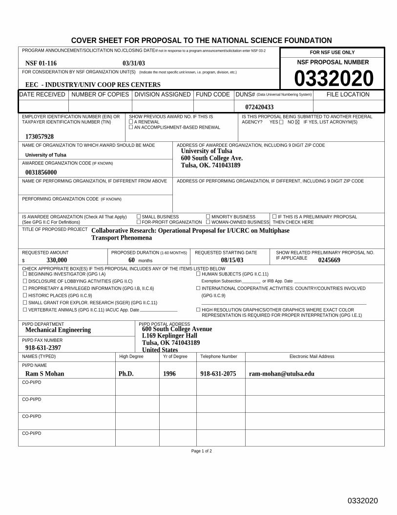
New NSF I/UCRC Proposal Summary
COVER SHEET FOR PROPOSAL TO THE NATIONAL SCIENCE FOUNDATIONFOR NSF USE ONLY
NSF PROPOSAL NUMBER
DATE RECEIVED NUMBER OF COPIES DIVISION ASSIGNED FUND CODE DUNS# (Data Universal Numbering System) FILE LOCATION
FOR CONSIDERATION BY NSF ORGANIZATION UNIT(S) (Indicate the most specific unit known, i.e. program, division, etc.)
PROGRAM ANNOUNCEMENT/SOLICITATION NO./CLOSING DATE/if not in response to a program announcement/solicitation enter NSF 03-2
EMPLOYER IDENTIFICATION NUMBER (EIN) ORTAXPAYER IDENTIFICATION NUMBER (TIN)
SHOW PREVIOUS AWARD NO. IF THIS ISA RENEWALAN ACCOMPLISHMENT-BASED RENEWAL
IS THIS PROPOSAL BEING SUBMITTED TO ANOTHER FEDERALAGENCY? YES NO IF YES, LIST ACRONYM(S)
NAME OF ORGANIZATION TO WHICH AWARD SHOULD BE MADE ADDRESS OF AWARDEE ORGANIZATION, INCLUDING 9 DIGIT ZIP CODE
AWARDEE ORGANIZATION CODE (IF KNOWN)
IS AWARDEE ORGANIZATION (Check All That Apply) SMALL BUSINESS MINORITY BUSINESS IF THIS IS A PRELIMINARY PROPOSAL(See GPG II.C For Definitions) FOR-PROFIT ORGANIZATION WOMAN-OWNED BUSINESS THEN CHECK HERE
NAME OF PERFORMING ORGANIZATION, IF DIFFERENT FROM ABOVE ADDRESS OF PERFORMING ORGANIZATION, IF DIFFERENT, INCLUDING 9 DIGIT ZIP CODE
PERFORMING ORGANIZATION CODE (IF KNOWN)
TITLE OF PROPOSED PROJECT
REQUESTED AMOUNT
$
PROPOSED DURATION (1-60 MONTHS)
months
REQUESTED STARTING DATE SHOW RELATED PRELIMINARY PROPOSAL NO.IF APPLICABLE
CHECK APPROPRIATE BOX(ES) IF THIS PROPOSAL INCLUDES ANY OF THE ITEMS LISTED BELOWBEGINNING INVESTIGATOR (GPG I.A)
DISCLOSURE OF LOBBYING ACTIVITIES (GPG II.C)
PROPRIETARY & PRIVILEGED INFORMATION (GPG I.B, II.C.6)
HISTORIC PLACES (GPG II.C.9)
SMALL GRANT FOR EXPLOR. RESEARCH (SGER) (GPG II.C.11)
VERTEBRATE ANIMALS (GPG II.C.11) IACUC App. Date
HUMAN SUBJECTS (GPG II.C.11)Exemption Subsection or IRB App. Date
INTERNATIONAL COOPERATIVE ACTIVITIES: COUNTRY/COUNTRIES INVOLVED
(GPG II.C.9)
HIGH RESOLUTION GRAPHICS/OTHER GRAPHICS WHERE EXACT COLORREPRESENTATION IS REQUIRED FOR PROPER INTERPRETATION (GPG I.E.1)
PI/PD DEPARTMENT PI/PD POSTAL ADDRESS
PI/PD FAX NUMBER
NAMES (TYPED) High Degree Yr of Degree Telephone Number Electronic Mail Address
PI/PD NAME
CO-PI/PD
CO-PI/PD
CO-PI/PD
CO-PI/PD
Page 1 of 2
0332020EEC - INDUSTRY/UNIV COOP RES CENTERS
NSF 01-116 03/31/03
173057928
University of Tulsa
0031856000
University of Tulsa600 South College Ave.Tulsa, OK. 741043189
Collaborative Research: Operational Proposal for I/UCRC on Multiphase Transport Phenomena
330,000 60 08/15/03 0245669
Mechanical Engineering
918-631-2397
600 South College AvenueL169 Keplinger HallTulsa, OK 741043189United States
Certification for Authorized Organizational Representative or Individual Applicant:By signing and submitting this proposal, the individual applicant or the authorized official of the applicant institution is: (1) certifying thatstatements made herein are true and complete to the best of his/her knowledge; and (2) agreeing to accept the obligation to comply with NSFaward terms and conditions if an award is made as a result of this application. Further, the applicant is hereby providing certificationsregarding debarment and suspension, drug-free workplace, and lobbying activities (see below), as set forth in GrantProposal Guide (GPG), NSF 03-2. Willful provision of false information in this application and its supporting documents or in reports requiredunder an ensuing award is a criminal offense (U. S. Code, Title 18, Section 1001). In addition, if the applicant institution employs more than fifty persons, the authorized official of the applicant institution is certifying that the institution has implemented a written and enforced conflict of interest policy that is consistent with the provisions of Grant Policy Manual Section 510; that to the bestof his/her knowledge, all financial disclosures required by that conflict of interest policy have been made; and that all identified conflicts of interest will havebeen satisfactorily managed, reduced or eliminated prior to the institution’s expenditure of any funds under the award, in accordance with theinstitution’s conflict of interest policy. Conflicts which cannot be satisfactorily managed, reduced or eliminated must be disclosed to NSF.
Drug Free Work Place Certification By electronically signing the NSF Proposal Cover Sheet, the Authorized Organizational Representative or Individual Applicant is providing the Drug Free Work Place Certification contained in Appendix A of the Grant Proposal Guide.
Debarment and Suspension Certification (If answer "yes", please provide explanation.)
Is the organization or its principals presently debarred, suspended, proposed for debarment, declared ineligible, or voluntarily excluded from covered transactions by any Federal department or agency? Yes No
By electronically signing the NSF Proposal Cover Sheet, the Authorized Organizational Representative or Individual Applicant is providing the Debarment and Suspension Certification contained in Appendix B of the Grant Proposal Guide.
Certification Regarding LobbyingThis certification is required for an award of a Federal contract, grant, or cooperative agreement exceeding $100,000 and for an award of a Federal loan ora commitment providing for the United States to insure or guarantee a loan exceeding $150,000.
Certification for Contracts, Grants, Loans and Cooperative AgreementsThe undersigned certifies, to the best of his or her knowledge and belief, that:
(1) No federal appropriated funds have been paid or will be paid, by or on behalf of the undersigned, to any person for influencing or attempting to influencean officer or employee of any agency, a Member of Congress, an officer or employee of Congress, or an employee of a Member of Congress in connectionwith the awarding of any federal contract, the making of any Federal grant, the making of any Federal loan, the entering into of any cooperative agreement,and the extension, continuation, renewal, amendment, or modification of any Federal contract, grant, loan, or cooperative agreement.
(2) If any funds other than Federal appropriated funds have been paid or will be paid to any person for influencing or attempting to influence an officer oremployee of any agency, a Member of Congress, an officer or employee of Congress, or an employee of a Member of Congress in connection with thisFederal contract, grant, loan, or cooperative agreement, the undersigned shall complete and submit Standard Form-LLL, ‘‘Disclosure of Lobbying Activities,’’ in accordance with its instructions.
(3) The undersigned shall require that the language of this certification be included in the award documents for all subawards at all tiers includingsubcontracts, subgrants, and contracts under grants, loans, and cooperative agreements and that all subrecipients shall certify and disclose accordingly.
This certification is a material representation of fact upon which reliance was placed when this transaction was made or entered into. Submission of thiscertification is a prerequisite for making or entering into this transaction imposed by section 1352, Title 31, U.S. Code. Any person who fails to file therequired certification shall be subject to a civil penalty of not less than $10,000 and not more than $100,000 for each such failure.
AUTHORIZED ORGANIZATIONAL REPRESENTATIVE SIGNATURE DATE
NAME
TELEPHONE NUMBER ELECTRONIC MAIL ADDRESS FAX NUMBER
*SUBMISSION OF SOCIAL SECURITY NUMBERS IS VOLUNTARY AND WILL NOT AFFECT THE ORGANIZATION’S ELIGIBILITY FOR AN AWARD. HOWEVER, THEY ARE ANINTEGRAL PART OF THE INFORMATION SYSTEM AND ASSIST IN PROCESSING THE PROPOSAL. SSN SOLICITED UNDER NSF ACT OF 1950, AS AMENDED.
Page 2 of 2
0332020
COVER SHEET FOR PROPOSAL TO THE NATIONAL SCIENCE FOUNDATIONFOR NSF USE ONLY
NSF PROPOSAL NUMBER
DATE RECEIVED NUMBER OF COPIES DIVISION ASSIGNED FUND CODE DUNS# (Data Universal Numbering System) FILE LOCATION
FOR CONSIDERATION BY NSF ORGANIZATION UNIT(S) (Indicate the most specific unit known, i.e. program, division, etc.)
PROGRAM ANNOUNCEMENT/SOLICITATION NO./CLOSING DATE/if not in response to a program announcement/solicitation enter NSF 03-2
EMPLOYER IDENTIFICATION NUMBER (EIN) ORTAXPAYER IDENTIFICATION NUMBER (TIN)
SHOW PREVIOUS AWARD NO. IF THIS ISA RENEWALAN ACCOMPLISHMENT-BASED RENEWAL
IS THIS PROPOSAL BEING SUBMITTED TO ANOTHER FEDERALAGENCY? YES NO IF YES, LIST ACRONYM(S)
NAME OF ORGANIZATION TO WHICH AWARD SHOULD BE MADE ADDRESS OF AWARDEE ORGANIZATION, INCLUDING 9 DIGIT ZIP CODE
AWARDEE ORGANIZATION CODE (IF KNOWN)
IS AWARDEE ORGANIZATION (Check All That Apply) SMALL BUSINESS MINORITY BUSINESS IF THIS IS A PRELIMINARY PROPOSAL(See GPG II.C For Definitions) FOR-PROFIT ORGANIZATION WOMAN-OWNED BUSINESS THEN CHECK HERE
NAME OF PERFORMING ORGANIZATION, IF DIFFERENT FROM ABOVE ADDRESS OF PERFORMING ORGANIZATION, IF DIFFERENT, INCLUDING 9 DIGIT ZIP CODE
PERFORMING ORGANIZATION CODE (IF KNOWN)
TITLE OF PROPOSED PROJECT
REQUESTED AMOUNT
$
PROPOSED DURATION (1-60 MONTHS)
months
REQUESTED STARTING DATE SHOW RELATED PRELIMINARY PROPOSAL NO.IF APPLICABLE
CHECK APPROPRIATE BOX(ES) IF THIS PROPOSAL INCLUDES ANY OF THE ITEMS LISTED BELOWBEGINNING INVESTIGATOR (GPG I.A)
DISCLOSURE OF LOBBYING ACTIVITIES (GPG II.C)
PROPRIETARY & PRIVILEGED INFORMATION (GPG I.B, II.C.6)
HISTORIC PLACES (GPG II.C.9)
SMALL GRANT FOR EXPLOR. RESEARCH (SGER) (GPG II.C.11)
VERTEBRATE ANIMALS (GPG II.C.11) IACUC App. Date
HUMAN SUBJECTS (GPG II.C.11)Exemption Subsection or IRB App. Date
INTERNATIONAL COOPERATIVE ACTIVITIES: COUNTRY/COUNTRIES INVOLVED
(GPG II.C.9)
HIGH RESOLUTION GRAPHICS/OTHER GRAPHICS WHERE EXACT COLORREPRESENTATION IS REQUIRED FOR PROPER INTERPRETATION (GPG I.E.1)
PI/PD DEPARTMENT PI/PD POSTAL ADDRESS
PI/PD FAX NUMBER
NAMES (TYPED) High Degree Yr of Degree Telephone Number Electronic Mail Address
PI/PD NAME
CO-PI/PD
CO-PI/PD
CO-PI/PD
CO-PI/PD
Page 1 of 2
0331977EEC - INDUSTRY/UNIV COOP RES CENTERS
NSF 01-116 03/31/03
386005984
Michigan State University
0022905000
Michigan State UniversityContracts & Grants DepartmentEast Lansing, MI. 488241046
Collaborative Research: Operating Proposal for I/UCRC on Multiphase Transport Phenomena
430,000 60 08/15/03 0245644
Chemical Engineering
517-432-1105
South Shaw Lane and Red Cedar Road2527 Engineering BuildingEast Lansing, MI 488241226United States
Certification for Authorized Organizational Representative or Individual Applicant:By signing and submitting this proposal, the individual applicant or the authorized official of the applicant institution is: (1) certifying thatstatements made herein are true and complete to the best of his/her knowledge; and (2) agreeing to accept the obligation to comply with NSFaward terms and conditions if an award is made as a result of this application. Further, the applicant is hereby providing certificationsregarding debarment and suspension, drug-free workplace, and lobbying activities (see below), as set forth in GrantProposal Guide (GPG), NSF 03-2. Willful provision of false information in this application and its supporting documents or in reports requiredunder an ensuing award is a criminal offense (U. S. Code, Title 18, Section 1001). In addition, if the applicant institution employs more than fifty persons, the authorized official of the applicant institution is certifying that the institution has implemented a written and enforced conflict of interest policy that is consistent with the provisions of Grant Policy Manual Section 510; that to the bestof his/her knowledge, all financial disclosures required by that conflict of interest policy have been made; and that all identified conflicts of interest will havebeen satisfactorily managed, reduced or eliminated prior to the institution’s expenditure of any funds under the award, in accordance with theinstitution’s conflict of interest policy. Conflicts which cannot be satisfactorily managed, reduced or eliminated must be disclosed to NSF.
Drug Free Work Place Certification By electronically signing the NSF Proposal Cover Sheet, the Authorized Organizational Representative or Individual Applicant is providing the Drug Free Work Place Certification contained in Appendix A of the Grant Proposal Guide.
Debarment and Suspension Certification (If answer "yes", please provide explanation.)
Is the organization or its principals presently debarred, suspended, proposed for debarment, declared ineligible, or voluntarily excluded from covered transactions by any Federal department or agency? Yes No
By electronically signing the NSF Proposal Cover Sheet, the Authorized Organizational Representative or Individual Applicant is providing the Debarment and Suspension Certification contained in Appendix B of the Grant Proposal Guide.
Certification Regarding LobbyingThis certification is required for an award of a Federal contract, grant, or cooperative agreement exceeding $100,000 and for an award of a Federal loan ora commitment providing for the United States to insure or guarantee a loan exceeding $150,000.
Certification for Contracts, Grants, Loans and Cooperative AgreementsThe undersigned certifies, to the best of his or her knowledge and belief, that:
(1) No federal appropriated funds have been paid or will be paid, by or on behalf of the undersigned, to any person for influencing or attempting to influencean officer or employee of any agency, a Member of Congress, an officer or employee of Congress, or an employee of a Member of Congress in connectionwith the awarding of any federal contract, the making of any Federal grant, the making of any Federal loan, the entering into of any cooperative agreement,and the extension, continuation, renewal, amendment, or modification of any Federal contract, grant, loan, or cooperative agreement.
(2) If any funds other than Federal appropriated funds have been paid or will be paid to any person for influencing or attempting to influence an officer oremployee of any agency, a Member of Congress, an officer or employee of Congress, or an employee of a Member of Congress in connection with thisFederal contract, grant, loan, or cooperative agreement, the undersigned shall complete and submit Standard Form-LLL, ‘‘Disclosure of Lobbying Activities,’’ in accordance with its instructions.
(3) The undersigned shall require that the language of this certification be included in the award documents for all subawards at all tiers includingsubcontracts, subgrants, and contracts under grants, loans, and cooperative agreements and that all subrecipients shall certify and disclose accordingly.
This certification is a material representation of fact upon which reliance was placed when this transaction was made or entered into. Submission of thiscertification is a prerequisite for making or entering into this transaction imposed by section 1352, Title 31, U.S. Code. Any person who fails to file therequired certification shall be subject to a civil penalty of not less than $10,000 and not more than $100,000 for each such failure.
AUTHORIZED ORGANIZATIONAL REPRESENTATIVE SIGNATURE DATE
NAME
TELEPHONE NUMBER ELECTRONIC MAIL ADDRESS FAX NUMBER
*SUBMISSION OF SOCIAL SECURITY NUMBERS IS VOLUNTARY AND WILL NOT AFFECT THE ORGANIZATION’S ELIGIBILITY FOR AN AWARD. HOWEVER, THEY ARE ANINTEGRAL PART OF THE INFORMATION SYSTEM AND ASSIST IN PROCESSING THE PROPOSAL. SSN SOLICITED UNDER NSF ACT OF 1950, AS AMENDED.
Page 2 of 2
Craig E ONeill Mar 31 2003 2:41PMElectronic Signature
COVER SHEET FOR PROPOSAL TO THE NATIONAL SCIENCE FOUNDATIONFOR NSF USE ONLY
NSF PROPOSAL NUMBER
DATE RECEIVED NUMBER OF COPIES DIVISION ASSIGNED FUND CODE DUNS# (Data Universal Numbering System) FILE LOCATION
FOR CONSIDERATION BY NSF ORGANIZATION UNIT(S) (Indicate the most specific unit known, i.e. program, division, etc.)
PROGRAM ANNOUNCEMENT/SOLICITATION NO./CLOSING DATE/if not in response to a program announcement/solicitation enter NSF 03-2
EMPLOYER IDENTIFICATION NUMBER (EIN) ORTAXPAYER IDENTIFICATION NUMBER (TIN)
SHOW PREVIOUS AWARD NO. IF THIS ISA RENEWALAN ACCOMPLISHMENT-BASED RENEWAL
IS THIS PROPOSAL BEING SUBMITTED TO ANOTHER FEDERALAGENCY? YES NO IF YES, LIST ACRONYM(S)
NAME OF ORGANIZATION TO WHICH AWARD SHOULD BE MADE ADDRESS OF AWARDEE ORGANIZATION, INCLUDING 9 DIGIT ZIP CODE
AWARDEE ORGANIZATION CODE (IF KNOWN)
IS AWARDEE ORGANIZATION (Check All That Apply) SMALL BUSINESS MINORITY BUSINESS IF THIS IS A PRELIMINARY PROPOSAL(See GPG II.C For Definitions) FOR-PROFIT ORGANIZATION WOMAN-OWNED BUSINESS THEN CHECK HERE
NAME OF PERFORMING ORGANIZATION, IF DIFFERENT FROM ABOVE ADDRESS OF PERFORMING ORGANIZATION, IF DIFFERENT, INCLUDING 9 DIGIT ZIP CODE
PERFORMING ORGANIZATION CODE (IF KNOWN)
TITLE OF PROPOSED PROJECT
REQUESTED AMOUNT
$
PROPOSED DURATION (1-60 MONTHS)
months
REQUESTED STARTING DATE SHOW RELATED PRELIMINARY PROPOSAL NO.IF APPLICABLE
CHECK APPROPRIATE BOX(ES) IF THIS PROPOSAL INCLUDES ANY OF THE ITEMS LISTED BELOWBEGINNING INVESTIGATOR (GPG I.A)
DISCLOSURE OF LOBBYING ACTIVITIES (GPG II.C)
PROPRIETARY & PRIVILEGED INFORMATION (GPG I.B, II.C.6)
HISTORIC PLACES (GPG II.C.9)
SMALL GRANT FOR EXPLOR. RESEARCH (SGER) (GPG II.C.11)
VERTEBRATE ANIMALS (GPG II.C.11) IACUC App. Date
HUMAN SUBJECTS (GPG II.C.11)Exemption Subsection or IRB App. Date
INTERNATIONAL COOPERATIVE ACTIVITIES: COUNTRY/COUNTRIES INVOLVED
(GPG II.C.9)
HIGH RESOLUTION GRAPHICS/OTHER GRAPHICS WHERE EXACT COLORREPRESENTATION IS REQUIRED FOR PROPER INTERPRETATION (GPG I.E.1)
PI/PD DEPARTMENT PI/PD POSTAL ADDRESS
PI/PD FAX NUMBER
NAMES (TYPED) High Degree Yr of Degree Telephone Number Electronic Mail Address
PI/PD NAME
CO-PI/PD
CO-PI/PD
CO-PI/PD
CO-PI/PD
Page 1 of 2
0331989EEC - INDUSTRY/UNIV COOP RES CENTERS
NSF 01-116 03/31/03
346002924
University of Akron
0031237000
University of Akron302 East Buchtel AvenueAkron, OH. 443250001
Collaborative Research: Operational Proposal for I/UCRC on Multiphase Transport Phenomena
Certification for Authorized Organizational Representative or Individual Applicant:By signing and submitting this proposal, the individual applicant or the authorized official of the applicant institution is: (1) certifying thatstatements made herein are true and complete to the best of his/her knowledge; and (2) agreeing to accept the obligation to comply with NSFaward terms and conditions if an award is made as a result of this application. Further, the applicant is hereby providing certificationsregarding debarment and suspension, drug-free workplace, and lobbying activities (see below), as set forth in GrantProposal Guide (GPG), NSF 03-2. Willful provision of false information in this application and its supporting documents or in reports requiredunder an ensuing award is a criminal offense (U. S. Code, Title 18, Section 1001). In addition, if the applicant institution employs more than fifty persons, the authorized official of the applicant institution is certifying that the institution has implemented a written and enforced conflict of interest policy that is consistent with the provisions of Grant Policy Manual Section 510; that to the bestof his/her knowledge, all financial disclosures required by that conflict of interest policy have been made; and that all identified conflicts of interest will havebeen satisfactorily managed, reduced or eliminated prior to the institution’s expenditure of any funds under the award, in accordance with theinstitution’s conflict of interest policy. Conflicts which cannot be satisfactorily managed, reduced or eliminated must be disclosed to NSF.
Drug Free Work Place Certification By electronically signing the NSF Proposal Cover Sheet, the Authorized Organizational Representative or Individual Applicant is providing the Drug Free Work Place Certification contained in Appendix A of the Grant Proposal Guide.
Debarment and Suspension Certification (If answer "yes", please provide explanation.)
Is the organization or its principals presently debarred, suspended, proposed for debarment, declared ineligible, or voluntarily excluded from covered transactions by any Federal department or agency? Yes No
By electronically signing the NSF Proposal Cover Sheet, the Authorized Organizational Representative or Individual Applicant is providing the Debarment and Suspension Certification contained in Appendix B of the Grant Proposal Guide.
Certification Regarding LobbyingThis certification is required for an award of a Federal contract, grant, or cooperative agreement exceeding $100,000 and for an award of a Federal loan ora commitment providing for the United States to insure or guarantee a loan exceeding $150,000.
Certification for Contracts, Grants, Loans and Cooperative AgreementsThe undersigned certifies, to the best of his or her knowledge and belief, that:
(1) No federal appropriated funds have been paid or will be paid, by or on behalf of the undersigned, to any person for influencing or attempting to influencean officer or employee of any agency, a Member of Congress, an officer or employee of Congress, or an employee of a Member of Congress in connectionwith the awarding of any federal contract, the making of any Federal grant, the making of any Federal loan, the entering into of any cooperative agreement,and the extension, continuation, renewal, amendment, or modification of any Federal contract, grant, loan, or cooperative agreement.
(2) If any funds other than Federal appropriated funds have been paid or will be paid to any person for influencing or attempting to influence an officer oremployee of any agency, a Member of Congress, an officer or employee of Congress, or an employee of a Member of Congress in connection with thisFederal contract, grant, loan, or cooperative agreement, the undersigned shall complete and submit Standard Form-LLL, ‘‘Disclosure of Lobbying Activities,’’ in accordance with its instructions.
(3) The undersigned shall require that the language of this certification be included in the award documents for all subawards at all tiers includingsubcontracts, subgrants, and contracts under grants, loans, and cooperative agreements and that all subrecipients shall certify and disclose accordingly.
This certification is a material representation of fact upon which reliance was placed when this transaction was made or entered into. Submission of thiscertification is a prerequisite for making or entering into this transaction imposed by section 1352, Title 31, U.S. Code. Any person who fails to file therequired certification shall be subject to a civil penalty of not less than $10,000 and not more than $100,000 for each such failure.
AUTHORIZED ORGANIZATIONAL REPRESENTATIVE SIGNATURE DATE
NAME
TELEPHONE NUMBER ELECTRONIC MAIL ADDRESS FAX NUMBER
*SUBMISSION OF SOCIAL SECURITY NUMBERS IS VOLUNTARY AND WILL NOT AFFECT THE ORGANIZATION’S ELIGIBILITY FOR AN AWARD. HOWEVER, THEY ARE ANINTEGRAL PART OF THE INFORMATION SYSTEM AND ASSIST IN PROCESSING THE PROPOSAL. SSN SOLICITED UNDER NSF ACT OF 1950, AS AMENDED.
Page 2 of 2
Gerald M Parker Mar 31 2003 3:21PMElectronic Signature
National Science Foundation Industry/University Cooperative Research Center on Multiphase Transport Phenomena
Michigan State University The University of Akron, The University of Tulsa
A. 1
Section A. Project Summary
Computational multiphase transport phenomena (CMTP) is a frontier area of engineering research that broadly impacts many traditional and emerging technologies. Unfortunately, current multiphase transport models have not kept up with the rapid advancements in computational technologies. In response to this situation and the need for more efficient engineering design methods, a group of faculty at Michigan State University, The University of Akron, and The University of Tulsa has organized a pre-competitive, multiuniversity, multidisciplinary NSF Industry/University Cooperative Research Center (NSF I/UCRC) in the area of Multiphase Transport Phenomena (MTP).
Center research will focus on the further development, evaluation, and deployment of
next generation multiphase models for turbulent and non-turbulent flows as well as computational methods for rapid design and analysis of processes and equipment for a wide range of applications encountered in, but not limited to, the automotive, chemical, and petrochemical industries. Problem-oriented research related to 1) multiphase fluids, 2) multiphase phenomena in porous media, 3) multiphase mixing and reactions, 4) multiphase separations, and 5) multiphase turbulence will be addressed during the formative years of the Center. NSF funds will be used to promote long-term synergistic partnerships among industrial members and academic research groups at the three universities. Specific problem-oriented research projects will be identified in collaboration with industrial members of the Center.
Intellectual Merit of the Proposed Activity The academic research groups at the three
universities have significant complementary expertise and interest in the discovery and use of next generation multiphase transport phenomena models. The new Center will focus on the further development and validation of MTP models and computational methods motivated by problem-oriented research such as advanced filtration processes based on nanoscale fibers, multiphase separation processes related to the production of oil and gas in remote locations (subsea, downhole, and offshore), advanced fuel sprays and coking furnaces, fuel cells, and manufacturing processes involving complex fluids such as particulate suspensions, foams, emulsions, and multiphase polymeric fluids.
Broader Impacts of the Proposed Activity Industrial internships for pre-doctoral and
post-doctoral students will be an essential element of the training and technology transfer missions of NSF I/UCRC-MTP. Moreover, undergraduate and graduate student training in the use of current commercial CMTP codes will use case study problems proposed by industrial members. Akron, MSU, and Tulsa recently developed this approach as a summer workshop and Internet course on MTP under the NSF CRCD program. Thus, early training of students in the new Center will catalyze the integration of research and education as well as technology transfer in multiphase transport phenomena by bringing together experimental, theoretical, and computational experts from industry and academia.
0331977
TABLE OF CONTENTSFor font size and page formatting specifications, see GPG section II.C.
Section Total No. of Page No.*Pages in Section (Optional)*
Cover Sheet for Proposal to the National Science Foundation
A Project Summary (not to exceed 1 page)
B Table of Contents
C Project Description (Including Results from Prior
NSF Support) (not to exceed 15 pages) (Exceed only if allowed by aspecific program announcement/solicitation or if approved inadvance by the appropriate NSF Assistant Director or designee)
D References Cited
E Biographical Sketches (Not to exceed 2 pages each)
F Budget (Plus up to 3 pages of budget justification)
G Current and Pending Support
H Facilities, Equipment and Other Resources
I Special Information/Supplementary Documentation
J Appendix (List below. )
(Include only if allowed by a specific program announcement/solicitation or if approved in advance by the appropriate NSFAssistant Director or designee)
Appendix Items:
*Proposers may select any numbering mechanism for the proposal. The entire proposal however, must be paginated.Complete both columns only if the proposal is numbered consecutively.
1
1
29
6
60
13
6
3
16
0331977
TABLE OF CONTENTSFor font size and page formatting specifications, see GPG section II.C.
Section Total No. of Page No.*Pages in Section (Optional)*
Cover Sheet for Proposal to the National Science Foundation
A Project Summary (not to exceed 1 page)
B Table of Contents
C Project Description (Including Results from Prior
NSF Support) (not to exceed 15 pages) (Exceed only if allowed by aspecific program announcement/solicitation or if approved inadvance by the appropriate NSF Assistant Director or designee)
D References Cited
E Biographical Sketches (Not to exceed 2 pages each)
F Budget (Plus up to 3 pages of budget justification)
G Current and Pending Support
H Facilities, Equipment and Other Resources
I Special Information/Supplementary Documentation
J Appendix (List below. )
(Include only if allowed by a specific program announcement/solicitation or if approved in advance by the appropriate NSFAssistant Director or designee)
Appendix Items:
*Proposers may select any numbering mechanism for the proposal. The entire proposal however, must be paginated.Complete both columns only if the proposal is numbered consecutively.
1
0
1
6
1
3
16
0331989
TABLE OF CONTENTSFor font size and page formatting specifications, see GPG section II.C.
Section Total No. of Page No.*Pages in Section (Optional)*
Cover Sheet for Proposal to the National Science Foundation
A Project Summary (not to exceed 1 page)
B Table of Contents
C Project Description (Including Results from Prior
NSF Support) (not to exceed 15 pages) (Exceed only if allowed by aspecific program announcement/solicitation or if approved inadvance by the appropriate NSF Assistant Director or designee)
D References Cited
E Biographical Sketches (Not to exceed 2 pages each)
F Budget (Plus up to 3 pages of budget justification)
G Current and Pending Support
H Facilities, Equipment and Other Resources
I Special Information/Supplementary Documentation
J Appendix (List below. )
(Include only if allowed by a specific program announcement/solicitation or if approved in advance by the appropriate NSFAssistant Director or designee)
Appendix Items:
*Proposers may select any numbering mechanism for the proposal. The entire proposal however, must be paginated.Complete both columns only if the proposal is numbered consecutively.
1
0
1
6
1
3
16
0332020
National Science Foundation Industry/University Cooperative Research Center onMultiphase Transport Phenomena
Michigan State UniversityThe University of Akron, The University of Tulsa
- C.1 -
Section C. Project Description
C.1 Executive Summary
Rationale for a Center on Multiphase Transport Phenomena
Computational multiphase transport phenomena (CMTP) is a frontier area ofengineering research that broadly impacts many traditional and emerging technologies inthe automotive (transportation), biochemical, chemical, food, medical, mining,petrochemical, and pharmaceutical industries. In a Vision 2020 report several years ago,leaders from the chemical process industries identified computational technologies as oneof five critical areas for research and education in North America (see Technology Vision2020: The U.S. Chemical Industry, ACS, 1996). Other countries, like Japan, have alsoidentified multiphase transport phenomena as an area of strategic importance for futuretechnology development (Kolev, 2002).
Although significant progress has been made in understanding and implementingCMTP over the past ten years, the impact of CMTP on engineering design remainsisolated within specific disciplines and within different industrial sectors. Furthermore,current research on CMTP in academia is widely dispersed over many universities andinteractions among departments within the same university are rare. It is noteworthy thata Delphi Forecast on Modeling and Simulation Applications for the Automotive Industry(see OSAT, 1998) concluded that “current simulation codes are not sufficientlyconfigured and integrated to allow useful design work". According to this report, one ofthe most negative attributes of current transport phenomena computational design tools isthe time required to develop a simulation. This is not unique to the automotiveindustries, but also reflects the current situation in the chemical process industries(Thompson, 2002).
Vision Statement
In response to the above situation, Michigan State University, The University ofAkron, and The University of Tulsa has formed a multi-university, multi-disciplinaryIndustry/University Cooperative Research Center (I/UCRC) in the area of MultiphaseTransport Phenomena (MTP) under the auspices of the National Science Foundation.The new Center will provide a forum for industry/university cooperative research on thefurther development of next generation multiphase transport models and innovativecomputational design methods. Over the next ten years, I/UCRC-MTP intends to becomeone of the leading industry/university research groups in the area of multiphase transportphenomena.
0331977
National Science Foundation Industry/University Cooperative Research Center onMultiphase Transport Phenomena
Michigan State UniversityThe University of Akron, The University of Tulsa
- C.2 -
Mission Statement
I/UCRC-MTP will support the combined research and education mission of theNational Science Foundation in the area of CMTP by bringing together experimental,theoretical, and computational experts from industry and academia in order to 1) conductpre-competitive leading edge research related to emerging and traditional technologiesthat involve multiphase phenomena; 2) develop next generation MTP models; 3) developnext generation CMTP design tools; and, 4) develop innovative methods to effectivelytrain students and engineers in the use of CMTP tools.
Research Focus
Specific problem-oriented research topics will include challenge problems relatedto 1) multiphase fluids, 2) multiphase phenomena in porous media, 3) multiphase mixingand reactions, 4) multiphase separations, and 5) multiphase turbulence. Research duringthe formative stages of the center will address theoretical and computational barrierproblems in the above areas with a strong emphasis on transport phenomena in fluid/fluidand solid/fluid systems.
The Multiphase Fluids Group will develop improved models and computationalmethods for predicting the microstructure of complex fluids in confined flows and freejets. The results will support the development of advanced composite materials reinforcedby nanoscale fibers and particles (clays). The goal is to develop computational toolscapable of evaluating innovative strategies for manufacturing multiphase compositematerials.
The Porous Media Group aims to develop improved models and computationalmethods for quantifying multiphase flows and heat transfer through natural and syntheticporous media. The results will support the further development of high efficiency filtersfor diesel exhaust, soot removal from engine oils, gas phase coalescers, and oil/waterseparators. In addition, improved computational tools will be used to evaluate naturalconvection heat transfer processes within fuel cells and near subsea pipelines.
The Multiphase Mixing and Reactions Group will develop improved computationalmethods for tracking the motion of an interface between two immiscible fluids. Theresults will support the analysis of multiphase processes such as liquid jet breakup,environmental mixing of oil and water, coalescence of liquid droplets on fibers, thestability of liquid/gas interfaces encountered in liquid molding, fuel sprays, interfacialreactions, and fluid/fluid separations in hydrocyclones.
0331977
National Science Foundation Industry/University Cooperative Research Center onMultiphase Transport Phenomena
Michigan State UniversityThe University of Akron, The University of Tulsa
- C.3 -
The Multiphase Separations Group will develop computational methods forpredicting the separation of oil-water-gas and re-suspension of sand in oil-water-gasflows. The results will support the evaluation of subsea and surface oil-water-gas pipelineand separator designs and the strategic placement and performance of sand separators.
The Multiphase Turbulence Group will focus on developing methods to predict themean field velocity and the mean field pressure distributions for multiphase flows withstrong streamline curvature. Research results will support the analysis of hydrocycloneseparators, mixing of liquid and gases in furnace tubes, and liquid/gas sprays.
Benefits to Industry
The I/UCRC-MTP membership fee is $30,000 per year for the first five years.Other members, the Three Universities, and the National Science Foundation willleverage this investment. With fifteen members, the Center budget for the first year willbe $732,500. As the Center grows to thirty members, the annual membership fee will beleveraged by an annual budget of $1,355,000.
All members will sign the same Membership Agreement and will be equallyrepresented on the Industrial Advisory Board. Members will participate in strategicdecisions of the Center including the selection and evaluation of research projects. Allindustrial participants will have non-exclusive rights to the entire I/UCRC-MTP researchportfolio. In addition, each I/UCRC-MTP industrial member will have an opportunity toactively participate in I/UCRC-MTP research and education programs.
Most significantly, members will also have an opportunity to propose case studyproblems and/or specific research problems and topics. The case study problems will beused to train I/UCRC-MTP students on the use of current computational technologies.Postdoctoral students will develop simulations and/or experimental results in support ofthe case studies. These results will provide a baseline for identifying the need for newdevelopments and precompetitive research.
Technology transfer between the faculty/student research teams and industrialmembers will be promoted by the following infrastructure: 1) pre-doctoral and post-doctoral industrial internships; 2) the direct involvement of the industrial advisor on theresearch team; 3) the use of commercially available software to disseminate high impactresults; 4) web based submission of quarterly and annual reports; and, 5) biannualresearch retreats on different campuses.
0331977
National Science Foundation Industry/University Cooperative Research Center onMultiphase Transport Phenomena
Michigan State UniversityThe University of Akron, The University of Tulsa
- C.4 -
C.2 I/UCRC Program
The NSF Industry/University Cooperative Research Center (I/UCRC) program,which began twenty-three years ago, is one of the most successful programs in the UnitedStates (see Gray and Walters, 1998). The recently formed multi-university I/UCRC onMultiphase Transport Phenomena (MTP) at MSU complements more than fifty I/UCRCCenters currently operating throughout North America. Michigan State University is theLead University for I/UCRC-MTP. Affiliated universities include The University ofAkron and The University of Tulsa. Other universities will be invited to participate as theneed for additional research expertise arises.
Membership Agreement and Annual Fees
During the first Industrial Advisory Board Meeting, the non-academic memberswill approve bylaws that will be used to run the Center. The bylaws will become part ofthe Membership Agreement, which is contained in Section I.3 of this proposal. TheMembership Agreement closely follows the standard I/UCRC model agreement and hasalready been reviewed (and approved) by the National Science Foundation and the threeparticipating Universities. The Membership Agreement addresses intellectual propertyrights, publication delay policy, and other relevant issues. All members pay the sameannual fee of $30,000 for the first five years. Tables in Section F of this proposalillustrate how the membership fee will be leveraged with NSF funds and University fundsto support Center research and Center operations.
National Science Foundation Support
The National Science Foundation will support the operation of I/UCRC-MTP byproviding an annual grant of $50,000 to each university with five to nine members; eachuniversity with ten or more members will receive $70,000 per year. NSF funds will beused to operate the Center and to promote long-term synergistic industry/academicresearch partnerships. The Lead University (MSU) will receive an additional $10,000 foreach affiliated university to partially cover the additional costs of managing the Center.After the fifth year, NSF funding will gradually decline to zero. After the tenth year,I/UCRC-MTP will operate independently of the National Science Foundation.
Institutional Support: Faculty Resources
Twenty-seven faculty participants representing seven disciplines (ChemicalEngineering, Electrical Engineering, Material Science, Applied Mathematics, MechanicalEngineering, Petroleum Engineering, and Polymer Science) support the research andeducational goals of I/UCRC-MTP. The research interests and expertise of the faculty aresummarized in Section E.
0331977
National Science Foundation Industry/University Cooperative Research Center onMultiphase Transport Phenomena
Michigan State UniversityThe University of Akron, The University of Tulsa
- C.5 -
The faculty will make significant in kind contributions to the Center by recruitingand mentoring graduate students. The National Science Foundation offers manyopportunities for I/UCRC-MTP research teams to apply for supplemental funding tosupport precompetitive problem-oriented research projects, to support women graduatestudents, minority graduate students, and undergraduate students. Individual I/UCRC-MTP funded projects will be enhanced significantly by faculty members takingadvantage of these opportunities.
Institutional Support: Cost Share
The participating universities will partially support the ongoing costs associatedwith the research and operation of the Center by providing a cost share equivalent to 25%of the total membership fees. University certification letters for this support weresubmitted in the September 2002 Planning Proposal and are reproduced in Section I.1 ofthis operational proposal.
Institutional Support: Commitment to Center Growth
During the first year of operation, each university will have five or more sponsorsthat will pay an annual membership fee of $30,000 each. With a total of fifteen sponsors,the first year operating budget will be $732,500, which leverages an individualmembership fee by more than a factor of 24:1. The total budget for the first year includesmembership fees at $450,000 (~ 62% of total), university cost share at $112,500 (~15%of total), and NSF funds at $170,000 (~ 23% of total). This level of funding will partiallysupport four graduate students at each university for a total of twelve students in the firstyear of operation.
The Center will grow over the first three years by adding five or more newmembers per year. Funding from the National Science Foundation will increase as newmembers are added. With thirty members, the total annual budget for the Center will be$1,355,000, which leverages an individual membership fee of $30,000 by more than afactor of 45:1. The total annual budget for a 30-member Center will include membershipfees of $900,000 (~ 66% of the total), university cost share at $225,000 (~ 17% of thetotal), and a NSF grant of $230,000 per year (~ 17%). This level of funding will supporteight graduate students at each university for a total of twenty-four I/UCRC-MTPgraduate students.
Institutional Support: Research Facilities
The computational and experimental facilities at the three universities provide aunique opportunity for research (and education) in the area of multiphase transportphenomena. A brief description of available resources is given in Section H. Graduatestudents and faculty will also have limited access to state-of-the-art facilities at industrialsites and National Laboratories (see letters-of-intent in Section I.4). Table E.1 in SectionE summarizes the experimental, theoretical, and computational expertise of the faculty.
0331977
National Science Foundation Industry/University Cooperative Research Center onMultiphase Transport Phenomena
Michigan State UniversityThe University of Akron, The University of Tulsa
- C.6 -
Benefits to Industry
The I/UCRC-MTP membership fee is $30,000 per year for the first five years.Other members, the Three Universities, and the National Science Foundation willleverage this investment. With fifteen members, the Center budget for the first year willbe $732,500. As the Center grows to thirty members, the annual membership fee will beleveraged by an annual budget of $1,355,000.
All members will sign the same Membership Agreement (see Section I.3) and willbe equally represented on the Industrial Advisory Board. Members will participate instrategic decisions of the Center including the selection and evaluation of researchprojects. All members will have non-exclusive rights to the entire I/UCRC-MTP researchportfolio. In addition, each I/UCRC-MTP industrial member will have an opportunity toactively participate in I/UCRC-MTP research and education programs.
Most significantly, members will also have an opportunity to propose case studyproblems and/or specific research problems and topics. The case study problems will beused to train I/UCRC-MTP students on the use of current computational technologies.Postdoctoral students will develop simulations and/or experimental results in support ofthe case studies. These results will provide a baseline for identifying the need for newdevelopments and precompetitive research. Section C.6 of this proposal summarizes theresults of a recent NSF curriculum development project on multiphase transportphenomena based on industrial case study examples. The new Center will adopt thisparadigm to train new students on the use of commercial computational multiphasetransport phenomena codes.
Technology transfer between the faculty/student research teams and industrialmembers will be promoted by the following infrastructure: 1) pre-doctoral and post-doctoral industrial internships; 2) the direct involvement of the industrial advisor on theresearch team; 3) the use of commercially available software to disseminate high impactresults; 4) web based submission of quarterly and annual reports; and, 5) biannualresearch retreats on different campuses.
In summary, I/UCRC-MTP members will receive multiple benefits including• Participation in the strategic planning of I/UCRC-MTP.
• Opportunity to propose specific research and/or training problems.
• Selection of precompetitive research projects.
• A 24:1 leverage of annual membership fees ($30,000) in the first year for a 15-member Center.
• A 45:1 leverage of annual membership fees ($30,000) in Years 2-5 with a 30-member Center.
• Non-exclusive rights to the entire I/UCRC-MTP research portfolio.
• Sponsorship of postdoctoral research associates and/or graduate students as industrial interns.
• Technology transfer assurance as described above.
0331977
National Science Foundation Industry/University Cooperative Research Center onMultiphase Transport Phenomena
Michigan State UniversityThe University of Akron, The University of Tulsa
- C.7 -
C.3 Organizational Structure
Center Director, Co-Director, and Site Directors
The Director of the Center will be responsible for all Center activities and willreport directly to the Dean of Engineering at MSU as well as to the NSF ProgramManager and the Industrial Advisory Board. The Co-Director will be responsible for theresearch portfolio of the Center. The Director and Co-Director will work with the SiteDirectors and the Industrial Advisory Board on strategic planning related to the Centerand on recruiting new members. The Site Directors will be responsible for activities atthe individual universities.
Industrial Advisory Board
Although individual members join I/UCRC-MTP through one of the three affiliateduniversities, there is only one industrial advisory board (IAB) for the Center. Members ofIAB will 1) assist the faculty in identifying precompetitive generic research topics inmultiphase transport phenomena, 2) recommend research projects for funding, 3) assist inidentifying appropriate industrial internship opportunities for graduate students andpostdoctoral students, 4) assist the Center Director and Co-Director in identifying newI/UCRC-MTP members, 5) review the research and educational accomplishments of theCenter.
The Industrial Advisory Board will meet twice a year to review research results andto discuss the strategic plans for the Center. These meeting will occur at the participatinguniversities on a rotating basis. The IAB review meetings will coincide with the biannualI/UCRC-MTP research retreats.
External Evaluator
A Center Evaluator will work with the faculty and the Industrial Advisory Board toassess recruitment and retention strategies, training goals, and the compatibility ofmultidisciplinary cooperative research goals and Ph.D. dissertation goals. An assessmentprocedure will determine (1) whether the objectives are realized as program outcomes;(2) whether the objectives are appropriate; and, (3) how the program may be improved.The following performance measures will be employed: 1) membership satisfaction; 2)number of peer-reviewed journal publications, conference proceedings, andpresentations; 3) retention of Ph.D. students; 4) enrollment and impact of I/UCRC-MTPworkshops on students; and, 5) outcomes and utility of industrial case study problems inproviding focus for research.
University Policy Committee
The Associate Dean of Research and Graduate Studies in the College ofEngineering at MSU and the Dean of the Graduate School at MSU will form a multi-
0331977
National Science Foundation Industry/University Cooperative Research Center onMultiphase Transport Phenomena
Michigan State UniversityThe University of Akron, The University of Tulsa
- C.8 -
university administrative oversight committee to provide an annual review of academicstandards, recruitment strategies, retention issues, and funding issues related to theCenter. The Center Director and the Center Co-Director will serve on this committee.
Academic Advisory Committee
The Director of the Center will appoint faculty to serve on a multiuniversityAcademic Advisory Committee that will 1) set standards for student participation, 2)monitor student progress towards a degree, 3) set goals for recruiting students (especiallyminority and women), 4) promote the multidisciplinary nature of the research program,and 5) help students in organizing industrial internships. The five members of the FacultyLeadership Team will all serve on the Academic Advisory Committee.
C.4 Management Plan
Faculty Leadership Team
The center leadership team includes André Bénard, Charles Petty, and Tom Shih atMichigan State University, George Chase at The University of Akron, and Ram Mohan atThe University of Tulsa. This group has been collaborating together for more than threeyears on projects related to multiphase transport phenomena (see Section C.6). They havecollaborated with one another during the planning phase of forming the Center, whichincluded two industry/academic workshops at Michigan State University on September
0331977
National Science Foundation Industry/University Cooperative Research Center onMultiphase Transport Phenomena
Michigan State UniversityThe University of Akron, The University of Tulsa
- C.9 -
10, 2002 and February 19, 2003. A summary of each workshop is presented in SectionI.2. The leadership team is committed to the formation and the successful operation ofI/UCRC-MTP. A brief biographical sketch of each leader is given in Section E. Theleaders have made the following commitments to manage I/UCRC-MTP.
André Bénard, Associate Professor of Mechanical Engineering at Michigan StateUniversity, will serve as Co-Director of the Center and Group Leader of the I/UCRC-MTP focus area on multiphase fluids. As Center Co-Director, Professor Bénard will haveoversight responsibilities related to Center research at all three universities and willcoordinate research project assignments in cooperation with the Center Director, theResearch Foci Leaders, and the Industrial Advisory Board.
George Chase, Professor of Chemical Engineering and former Director of theMicroscale Physicochemical Engineering Center at The University of Akron, will serveas the Akron Site Director and the Group Leader for the I/UCRC-MTP focus area onmultiphase phenomena in porous media. Professor Chase will be responsible for 1)organizing and coordinating the I/UCRC-MTP biannual meetings with the other SiteDirectors, 2) recruiting new members to join the Center through Akron, 3) providingliaison between I/UCRC-MTP and the members that join the Center through Akron, and4) working with the academic departments and faculty to recruit graduate students forI/UCRC-MTP at Akron. As the NSF Principal Investigator at Akron, Professor Chasewill also be responsible for all center-related activities at Akron and will report to theDirector of the Center at MSU, to the Dean of the College of Engineering at Akron, andto the National Science Foundation.
Ram Mohan, Associate Professor of Mechanical Engineering and AssociateDirector of Tulsa University Separation Technology Projects, will serve as the Tulsa SiteDirector and Group Leader for the I/UCRC-MTP focus area on multiphase separations.Professor Mohan will be responsible for 1) organizing and coordinating the I/UCRC-MTP biannual meetings with the other Site Directors, 2) recruiting new members to jointhe Center through Tulsa, 3) providing liaison between I/UCRC-MTP and the membersthat join the Center through Tulsa, and 4) working with the academic departments andfaculty to recruit graduate students for I/UCRC-MTP at Tulsa. As the NSF PrincipalInvestigator at Tulsa, Professor Mohan will also be responsible for all center-relatedactivities at Tulsa and will report to the Director of the Center at MSU, to the Dean of theCollege of Engineering at Tulsa, and to the National Science Foundation.
0331977
National Science Foundation Industry/University Cooperative Research Center onMultiphase Transport Phenomena
Michigan State UniversityThe University of Akron, The University of Tulsa
- C.10 -
Charles Petty, Professor of Chemical Engineering and Director of the MultiphaseFlow Facility (MFF) at Michigan State University, will serve as the Center Director andas the Group Leader for the I/UCRC-MTP focus area on multiphase turbulence. AsCenter Director, Professor Petty will be responsible for all Center activities and willprovide liaison between the Center and the College of Engineering at MSU, the NationalScience Foundation, the Industrial Advisory Board, and the three Site Directors. Incooperation with the three Site Directors and the Center Co-Director, Professor Petty willbe responsible for ongoing industrial relations and recruitment of new Center Members.
Tom Shih, Professor of Mechanical Engineering and Director of the MultiphysicsComputational Research Laboratory (MCRL) at Michigan State University, will serve asthe MSU Site Director and Group Leader for the I/UCRC-MTP focus area on multiphasemixing and reactions. Professor Shih will be responsible for 1) organizing andcoordinating the I/UCRC-MTP biannual meetings with the other Site Directors, 2)recruiting new members to join the Center through MSU, 3) providing liaison betweenI/UCRC-MTP and the members that join the Center through MSU, and 4) working withthe academic departments and faculty to recruit graduate students for I/UCRC-MTP atMSU.
Administrative Support Staff
The Multiphase Flow Facility (MFF) in Chemical Engineering and theMultiphysics Computational Research Laboratory (MCRL) in Mechanical Engineeringwill provide administrative space for Center operations. A part time PostdoctoralAssociate and/or an Administrative Assistant will facilitate the daily technicalmanagement and technology transfer functions associated with the MSU Site. Anaccountant in the College of Engineering will provide liaison between the Center and theContract and Grant Administration Office at MSU.
The Microscale Physicochemical Engineering Center will provide a focal point forI/UCRC-MTP activities at Akron. A part time Postdoctoral Associate and/or anAdministrative Assistant will facilitate the daily technical management and technologytransfer functions associated with the Akron Site. An accountant in the College ofEngineering will provide liaison between the Center and the Contract and GrantAdministration Office at Akron.
University Separation Technology Projects will provide a focal point for I/UCRC-MTP activities at Tulsa. A part time Postdoctoral Associate and/or an AdministrativeAssistant will facilitate the daily technical management and technology transfer functionsassociated with the Tulsa Site. An accountant in the College of Engineering will provideliaison between the Center and the Contract and Grant Administrative Office at Tulsa.
0331977
National Science Foundation Industry/University Cooperative Research Center onMultiphase Transport Phenomena
Michigan State UniversityThe University of Akron, The University of Tulsa
- C.11 -
Technology Transfer
Technology transfer between the faculty/student research teams and industrialmembers will be promoted by the following infrastructure: 1) pre-doctoral and post-doctoral industrial internships; 2) the direct involvement of the industrial advisor on theresearch team; 3) the use of commercially available software to disseminate high impactresults; 4) web based submission of quarterly and annual reports; and, 5) biannualresearch retreats on different campuses.
Student Recruitment and Plan for Diversity
The IUCRC-MTP recruiting plan will be coordinated with individual academicdepartments. I/UCRC-MTP faculty participants will recruit graduate students through theregular departmental recruiting structure. The academic departments will administerstudent and faculty appointments in I/UCRC-MTP. The two academic co-advisors on thestudents research committee will serve as liaison between the Center and theDepartmental Graduate Committees.
Michigan State University has several innovative and tested programs to recruit andretain underrepresented students. Professor Percy Pierre at MSU, who is nationallyrecognized for his programs on recruiting, mentoring, and retaining minority and womengraduate students in engineering, has agreed to assist the faculty in attracting minoritydoctoral students to the I/UCRC-MTP program. These students will participate in theretention activities associated with the MSU/Sloan Engineering Program. New studentswill attend a specially designed orientation program for doctoral students as well asparticipate in weekly meetings with other minority students. Similar programs at Akronand Tulsa will be coordinated with the MSU program.
The three NSF Principal Investigators (Chase, Mohan, and Petty) will submitannual supplemental proposals to NSF and other appropriate organizations to enhance theparticipation of minority students and women in the Center.
Graduate Student Training
Each MTP graduate student will have two academic mentors and, if available, oneindustrial mentor. The two faculty mentors are responsible for advising the student onuniversity and departmental policies. During the first year in the program, an I/UCRC-MTP graduate student will participate in a CFD design group with a focus on anindustrial challenge problem as well as complete an Internet course on multiphasetransport phenomena (see Section C.6 below). In the second year, the student willcomplete an industrial internship. All I/UCRC-MTP graduate students will write a Masterof Science thesis and/or a Ph.D. dissertation.
0331977
National Science Foundation Industry/University Cooperative Research Center onMultiphase Transport Phenomena
Michigan State UniversityThe University of Akron, The University of Tulsa
- C.12 -
C.5 Financial Plan
The major source of funds for the Center will be membership fees ($30,000 peryear per member) from industry and other organizations The Universities will provide acost share equal to 25% of the membership fee and the National Science Foundation willprovide a grant to each University to partially fund the operation of the Center. Memberswill join the Center through one of the affiliated universities. I/UCRC-MTP will becomefully operational once each University has received a commitment from five or moreorganizations. The sources of funds for the first year are as follows: 1) membership feesfrom fifteen Members for a total of $450,000; 2) university cost share at $112,500; and3) a National Science Foundation grant of $170,000. Tables in Section F illustrate howCenter funds will be used to support Center research and operations in the first year aswell as in Years 2-5.
An I/UCRC-MTP research project will usually require two or more industrialsponsors to participate fully in Center activities. Therefore, multiple membership feeswill be used to support an individual project (∼ $47,000 per project). A proposedprocedure for selecting individual projects is briefly described in Section C.7 below.
During the first year of operation, twelve full-time (20 hours per week) graduatestudents and three part-time (20%) postdoctoral associates will be funded by the Center.The Center intends to recruit additional sponsors (federal government, state government,foundations, and other companies) to increase the membership fees to $900,000 (seeSection F for five-year budget). With this level of support, the center would have anannual budget of $1,355,000 and would partially fund the research of twenty-fourgraduate students in the area of multiphase transport phenomena.
C.6 Previous NSF Support Closely Related to this Proposal
NSF/ECC-9980325: November 1999-March 2003, Combined Research and CurriculumDevelopment on Multiphase Transport PhenomenaPrincipal Investigator:Charles A. PettyNSF Program Manager:Mary F. PoatsUniversity Participants:Michigan State University, The University of Akron, and The University of TulsaFaculty Participants:M. J. Amey (College of Education, MSU), A. Bénard (ME, MSU), G. G. Chase (ChE, Akron), E. A. Evans(ChE, Akron), K. Jayaraman (ChE, MSU), R. S. Mohan (ME, Tulsa), S. M. Parks (ChE, MSU), C. A. Petty(ChE, MSU), O. Shoham (PE, Tulsa), S. A. Shirazi (ME, Tulsa), K. D. Wisecarver (ChE, Tulsa), M.Zhuang (ME, Tulsa)Undergraduate Student Participants:Katharine Baker (ChE, MSU), Christina Berger (ChE, MSU), Dina Eldein (ChE, MSU), Floyd. Hammond(PE, Tulsa), Troy Hendricks (ChE, MSU), Nick Lynn (ME, MSU), Steve Leibrandt (ME, MSU), Luwi
0331977
National Science Foundation Industry/University Cooperative Research Center onMultiphase Transport Phenomena
Michigan State UniversityThe University of Akron, The University of Tulsa
- C.13 -
Oluwole (ChE, MSU), Carl Rose (ChE, MSU), S. Jose Severino (PE, Tulsa), Stephanie Teich-McGoldrick(ChE, MSU), Chad Trainer (PE, Tulsa), Sara Vermillion (ChE, Akron), William Wehbe (ME, MSU), AndyYoder (Che, MSU),Graduate Student Participants:Luis Gomez (PE, Tulsa), YoChan Kim (ChE, MSU), Figen Lacin (ME, MSU), Hongmin Li (ME, Akron),Dilip Mandal (ME, MSU), Brian Raber (ChE, Akron)Industrial Participants:AEA Technology Engineering Software Inc., Bechtel Technology and Consulting, ChevronTexaco, TheDow Chemical Company, DuPont Central Research & Development, Eastman Chemical Company,ExxonMobile Production Company, Fluent Incorporated, Krebs Engineers, Pharmacia, The Procter &Gamble Company, and The Trane Company.
Summary of CRCD-MTP
This curriculum development project on multiphase transport phenomenacombined the research experiences of nine research laboratories at The University ofAkron, Michigan State University, and the University of Tulsa. The objective of theproject was to develop a new curriculum for teaching students multiphase computationalfluid dynamics for advanced design. The CRCD-MTP teaching paradigm will be adoptedby I/UCRC-MTP as a means to rapidly introduce students to research in the area ofmultiphase transport phenomena.
The impact of multiphase flow research on solving practical engineering problemsis an integral part of the CRCD-MTP learning experience. Industrial participants in theproject provide specific design problems related to emerging or traditional technologies.Students are taught the fundamentals of computational fluid dynamics (CFD) during aone-week workshop. This is followed by an Internet course on multiphase transportphenomena. The students work in teams on CFD design problems with a faculty andindustrial mentor. The salient results of this NSF/CRCD project were recently presentedas part of the NSF Showcase at the 2002 ASEE Annual Conference & Exposition inMontreal, Canada (June 16-19) and at ICEE-2002, the International Conference onEngineering Education in Manchester, UK (August 18-22).
Need for a Multiphase Transport Phenomena Curriculum
Multiphase transport phenomena research is of industrial and national importance.Advances in oil and gas production, composite material processing, bioremediation ofsoils, plastic recycling, modern biotechnology reactors and separators, high-performancefiltration devices, nuclear fuel reprocessing, and efficient automotive fuel utilizationrepresent a few disparate engineering problems that rely on a basic fundamentalunderstanding of multiphase transport phenomena.
This curriculum development focused on the need to bridge an educational gapbetween undergraduate training in transport phenomena of single-phase fluids asexemplified by Bird et al. (2002) and transport phenomena of multiphase fluids (see, forexample, Gidaspow, 1994; Drew and Passman, 1999; and Kolev, 2002). Moreover, a
0331977
National Science Foundation Industry/University Cooperative Research Center onMultiphase Transport Phenomena
Michigan State UniversityThe University of Akron, The University of Tulsa
- C.14 -
significant gap is developing on the use of conventional transport phenomena principlesand computational fluid dynamic tools in the area of single-phase and multiphaseturbulent flows (Crow et al., 1996; Pope, 2000). CFD has opened the possibilities ofanalyzing in the classroom flows in complex geometries unimagined ten to twenty yearsago. However, students (and faculty) need further training to effectively use modern CFDcodes and to understand how CFD results can be used as an innovative process designand diagnostic tool.
Goals of CRCD-MTP
The overall goal of the NSF CRCD-MTP project was to develop and implement amultiphase transport phenomena course across professional disciplines. The structure ofthe curriculum addresses the following eight educational needs for advancedundergraduate students, beginning graduate students, and industrial postgraduatestudents: 1) training in fundamentals of multiphase transport phenomena; 2) training inthe development of multiphase model formulation, interpretation, and experimentalvalidation; 3) training in the fundamentals of numerical methods that support currentstate-of-the-art commercial CFD codes; 4) training in the implementation of CFD codes;5) training in the use of CFD codes for non-turbulent flows of single phase fluids; 6)training in the use of CFD codes for turbulent flows of single phase fluids; 7) training inthe application of multiphase CFD codes; and, 8) training in the integration of CFD toolsinto the design process.
Organization of the CRCD-MTP Training Program
CRCD-MTP CFD Bootcamp The CFD bootcamp was conducted at MSU for aweek in August 2000, June 2001, and June 2002. Approximately twenty undergraduateand graduate students participated each year. The students reviewed key ideas associatedwith single-phase transport phenomena, conducted practical hands-on experimentsrelated to single phase and multiphase materials and learned to use a commercial CFDcode (i.e., CFX during the first year; Fluent during the second and third years).
Each student was a member of a CFD design team. Each team met with anindustrial mentor to discuss a CFD case study of interest to the industrial participant (seeTable C.3 above). The teams completed a case study design during the summer andpresented the results of their work at professional meetings.
Internet Course on Multiphase Transport Phenomena An Internet coursecomplements the CFD design experience by offering the following topical lectures:Intraphase and Interphase Transport Phenomena; Transport Phenomena in MultiphaseFluids; Computational Fluid Dynamics; Gas/Liquid, Solid/Liquid, and Liquid/LiquidFlows; Transport Phenomena in Porous Media; and, CFD Case Study Examples. Apreview of the CRCD-MTP program is located at www.vu.msu.edu/preview/eng-mtp.
National Science Foundation Industry/University Cooperative Research Center onMultiphase Transport Phenomena
Michigan State UniversityThe University of Akron, The University of Tulsa
- C.15 -
Computational Fluid Dynamics Case Studies CRCD-MTP student teamscompleted six industrial CFD case studies. Table C.3 below identifies the titles of theprojects and the participants.
Table C.3 CFD Design Projects and ParticipantsTeam A: Numerical Simulation of a Solid/Fluid Suspension in an Enclosed TankTeam B: Numerical Simulation of Flow within a HVAC HeaderTeam C: Numerical Simulation of a Bubble ColumnTeam D: CFD Study of Water/Oil Dispersions in a Distribution ManifoldTeam E: Influence of Cone Angle and Capacity on Hydrocyclone SeparatorsTeam F: CFD Simulation of a Pulsed-Jet Mixer
Team CompanyHost University
IndustrialAdvisor
AcademicAdvisor
GraduateStudent Mentor
UndergraduateStudent
A PharmaciaMSU Mark Widman Steve Parks
Charles Petty YoChan KimC. BergerC. Rose
A. Yoder
BThe TraneCompany
MSURay Rite André Bénard
Mei ZhuangFigan Lacin
Dilip MandalD. El-deinN. Lynn
C Eastman ChemicalAkron Kevin Fontenot George Chase
Edward EvansBrian RaberHongmin Li
K. BakerT. HendricksS. Vermillion
D Chevron-TexacoTulsa Gene Kouba Ram Mohan
Ovadia Shoham Luis GomezF. HammondS. LeibrandtJ. Severino
E Krebs EngineersMSU Tim Olson Steven Parks
Charles PettyL. OluwoleW. Wehbe
F BechtelMSU
BrigetteRosendall
Charles PettySteve Parks
D. EldeinS. T-McGoldrick
C. Trainer
0331977
National Science Foundation Industry/University Cooperative Research Center onMultiphase Transport Phenomena
Michigan State UniversityThe University of Akron, The University of Tulsa
- C.16 -
C.7 Research Plan
Background and Premise
Multiphase fluids occur ubiquitously in engineering applications and involvedispersed two-phase flows such as fiber suspensions, emulsions, and foams. Modelingand simulating these systems challenge current physical understanding and currentcomputational resources. Indeed, multiphase flows are often unstable and involve large-scale secondary motions, and buoyancy effects. Secondary flows can significantlyinfluence multiphase mixing, multiphase separation, interfacial mass and heat transfer,and multiphase reactions. Unfortunately, current multiphase models for mass, energy, andmomentum transport often invoke ad hoc (and untested) assumptions that misrepresentthe influence of important physical phenomena on space-time scales encountered in MTPproblems. This situation significantly limits the use of advanced computational methodsfor innovative engineering design and research.
Significant gains are anticipated by sharing knowledge and methodologies in thismultidisciplinary Center, which will examine automotive and transportation inspiredapplications along side chemical and petrochemical inspired applications. For example, inorder to bridge nanoscale, microscale, mesoscale, and macroscale phenomena, currentMTP models use ensemble, volume, and/or time averaging techniques that require anidentification of specific space-time scales that control chemical kinetics, interfacialtransport processes, and turbulent mixing. These models are often discipline specific,even though they share common features.
Bénard (1996) and Bénard and Diaz (1998) have noted that the effort required tosimulate the flow within a complex domain can be so significant that it may take lesstime to study the key ideas experimentally. However, given the potential benefits ofsimulations in engineering design and optimization, the foregoing situation suggests thatthere is a need for a comprehensive re-evaluation of the modeling process, especially inthe area of computational multiphase transport phenomena (CMTP). This has justbecome possible through recent complementary developments in transport models andmesh generation techniques as well as advances in computer technology.
Clearly, additional research and training are needed for CMTP technology tobecome a widespread engineering design tool. I/UCRC-MTP research will address bothof these needs by improving the accuracy of the physical models currently available, andby improving the numerical methods used for simulations. Therefore, the Center willaddress precompetitive problems related to the further development of
• next generation multiphase transport models and their experimental validation,and
• novel computational methods for rapid analysis of multiphase processes
0331977
National Science Foundation Industry/University Cooperative Research Center onMultiphase Transport Phenomena
Michigan State UniversityThe University of Akron, The University of Tulsa
- C.17 -
Research Foci
I/UCRC-MTP research projects will examine problems related to the following fivefocus areas: 1) multiphase fluids, 2) multiphase phenomena in porous media, 3)multiphase mixing and reactions, 4) multiphase separations, and 5) multiphaseturbulence. Research during the formative stages of the center will address theoreticaland computational barrier problems with a strong emphasis on transport phenomena influid/fluid and solid/fluid systems. Precompetitive research topics were identified bycompany representatives at the I/UCRC-MTP planning meetings on September 10,2002and on February 19-20, 2003 (see Section I.2 for a summary of the planning meetings).
Identification and Selection of Research Projects -- Member Participation
Although individual members join the Center through one of the three affiliateduniversities, there is only one industrial advisory board (IAB). All members willparticipate in the selection and evaluation of research projects. Most significantly, IABmembers will also have an opportunity to propose specific problem-oriented researchtopics and precompetitive research areas of interest.
During the first few months of operation, a portfolio of relevant research topics willbe compiled based on the interest of IAB members and the five focus groups. Theseresearch topics will be posted on the Center web site and will form the basis forcollaborative projects. Each focus group will develop a set of proposals consistent withthe goals of their group (see below), the interest of members, and the mission of theCenter. IAB members will review the faculty research proposals prior to the I/UCRC-MTP research meeting. At the meeting, faculty/student teams will discuss their proposalswith IAB members.
All I/UCRC-MTP research projects will be developed by students and supervisedby faculty. Each project will require two or more industrial sponsors. Members of IABwill develop bylaws that will identify procedures for selecting projects. Members willhave an opportunity to fund one or more projects at different universities or at the sameuniversity. Problem-oriented research projects are often broad enough in scope thatcomplementary expertise and knowledge from all three universities will be needed toaddress relevant research issues. Significant resources for research are available toI/UCRC-MTP members in terms of faculty (see Section E) and state-of-the-art researchtechnologies (see Section H).
An example research problem from each of the research focus areas is describedbelow. This description stems, in part, from discussions with potential I/UCRC-MTPmembers that attended planning meetings either on September 10,2002 or February 19,2003. Section I.2 summarizes the results of these earlier planning meetings.
0331977
National Science Foundation Industry/University Cooperative Research Center onMultiphase Transport Phenomena
Michigan State UniversityThe University of Akron, The University of Tulsa
- C.18 -
C.7.1. Focus Area 1: Multiphase FluidsAndré Bénard, Group Leader
Faculty Resources:A. Bénard (MSU), G. Chase (Akron), E. Evans (Akron), K. Jayaraman (MSU),C. Lira (MSU), J. Lloyd (MSU), A. Lee (MSU), M. Mackay (MSU),C. Petty (MSU), D. Reneker (Akron), and G.Young (Akron)
The Multiphase Fluids Group will develop improved theoretical models andcomputational methods for predicting the microstructure of complex fluids in confinedflows and free jets. The results will support the development and use of advancedmaterials reinforced, for example, by nanoscale fibers and particles (clays). The goal ofthis group is to develop computational tools capable of evaluating innovative strategiesfor manufacturing multiphase composite materials.
Example Project: Die Design for Multiphase FluidsBackground
Manufacturing processes involving multiphase materials such as suspensions,immiscible polymers, or liquid crystalline polymers often result in parts withmicrostructures that are strongly coupled with the processing flow fields. Consequently,controlling the microstructure of the final composite can be achieved indirectly by flowcontrol. One possible approach is to extrude the multiphase fluid through a speciallydesigned die (see for example Goettler. and Lambright, 1977a, 1977b; Doshi, 1986). Thedesign procedure however is often tedious and time consuming since numerous dies mustoften be designed before the desired microstructure is obtained. The goal of this project isto develop a computational approach that can identify promising die designs for testing.
Predicting the orientation of the microstructure for complex fluids however is still asignificant challenge for engineers and scientists. While some successes have beenreported in the literature, especially for fiber suspensions, there is still a need forimproved models applied in complex flows. Tucker and Huynh (2001) very recentlyreported on the need for improving the accuracy of predictions in molds with short flow-lengths (i.e. thickness/length < 50). Although the origin of the discrepancies betweenpredictions and observations is not easy to pinpoint, the source of the problem could bethe closure model for the orientation tetradic, or the constitutive equation expressing thecoupling between the flow field and the microstructure.
The ability to predict changes in the microstructure of complex fluids duringprocessing will have an important impact on next generation processing strategies forpolymer and polymer-matrix composites. Such an approach may yield new fundamentalresults on the influence of complex flow patterns on the microstructure of liquidcrystalline polymers and other complex fluids.
0331977
National Science Foundation Industry/University Cooperative Research Center onMultiphase Transport Phenomena
Michigan State UniversityThe University of Akron, The University of Tulsa
- C.19 -
A. Benard and C. Petty have been involved with the problem of flow-inducedalignment of particles for nearly five years. The explicit representation used in the closuremodel developed at MSU complements the implicit closure models of Cintra and Tucker(1995) and Dupret et al. (1997). A few articles and patents have been published on semi-empirical design of extrusion dies (Goettler. and Lambright, 1977a, 1977b; Doshi, 1986),as well as processing methods to induce orientation of the microstructure (e.g. Baird andSukhadia, 1993; Handlos and Baird, 1995), none however involved numerical studies.
Predicting the response of suspensions to various flow fields encountered duringprocessing is often based on a moment equation of the average orientation dyadic. Aclosure model that relates the fourth order orientation tensor to the second orderorientation tensor was recently developed at MSU (Petty et al., 1999). This new algebraicclosure model retains all six contraction and symmetry properties of the exact fourthorder tensor. This new closure model allows understanding of the complex phenomenaassociated with the processing of short-fiber composites and the behavior of complexfluids such as liquid crystalline polymers.
This research aims to combine recent developments in numerical methods with newpredictive models for the microstructure of complex fluids in order to simulate extrusionprocesses in a novel way. The computational costs associated with such simulations canbe enormous due to the prohibitively large number of unknowns. Recent availability ofinexpensive parallel computers, large memories and fast chips however make thisproblem tractable.
Questions regarding the prediction and control of the microstructure of productsmade from multiphase materials are numerous (Guell and Papathanasiou, 1997). Specificproblem areas include:
• The formulation of realizable closure models to predict the behavior ofsuspensions or immiscible polymer blends during processing;
• Understanding the flow behavior of complex fluids during processing and theinstabilities associated with a processing methodology; and,
• Validation of multiphase averaging theories through detailed simulations andexperimental measurements at the microscale level.
Proposed Research
The MSU group has already developed and validated a closure model for the fourthorder orientation tensor. A two-dimensional finite element code that implements the newtheory for flow-induced alignment of particles is already available. With this software,the influence of geometrical on changes in the fluid microstructure (suspensions, liquidcrystalline polymers, bubbles, etc) can be ascertained. The software however must bedeveloped further to study flows in axisymmetric geometries and complex three-dimensional domains, which are important for industrial applications. Therefore, duringthe initial stages of this project, a finite element code will be developed to predict three-
0331977
National Science Foundation Industry/University Cooperative Research Center onMultiphase Transport Phenomena
Michigan State UniversityThe University of Akron, The University of Tulsa
- C.20 -
dimensional flow-induced orientation of a dispersed phase in complex geometries with anemphasis on the relationship between die geometry and the resulting microstructure forextruded profiles.
Research Methods
The finite element model will use the fictitious domain method to reduce themeshing requirements and reduce the design cycle time. Such methods use a regular grid,thus obviating the need for a boundary matching mesh, and the boundary conditions onthe surfaces are preserved by converting the surface integral into volume integrals usingmeasure theory concepts. Although the formulation of a successful fictitious domainapproximation is challenging, the strategy should nevertheless succeed for extrusionapplications inasmuch as successful fictitious domain strategies have already beendeveloped for a class of problems in heat conduction, elasticity, and flow (see, esp.,Astrakhantsev,1978; Diaz and DeRose, 1998; and Bertrand et al., 1997, Li and Bénard,2003). Particularly relevant to this work are the results presented by Glowinski andcolleagues (Glowinski et al., 1998, 1993).
Novelty of the Proposed Research, Anticipated Results, and Benefits
No systemic studies of using the die geometry to control flow and microstructurehave been presented in the literature. Such studies may yield novel geometrical designsthat will favor the orientation of the particles for a given application as discussed inGoettler and Lambright (1977a, 1977b), Doshi (1986), Baird and Sukhadia (1993) andHandlos and Baird (1995). Guidelines on the design of dies may also evolve from thiswork.
The fabrication of multiphase materials such as composites or alloys is a difficultproblem that involves complex transport phenomena. Significant advances have beenmade in manufacturing these materials, but there is still a need to understand relevanttransport phenomena during the processing stage (Advani, 1994; Wang, 1997). Importantproblems that affect the microstructure evolution of multiphase materials duringprocessing will be studied.
The materials considered will be polymer blends, polymer composites and metalalloys. Such materials, despite their differences, still follow the same fundamentalgoverning principles for mass, heat and momentum transfer. One must, however, stilldevelop specific closure models and determine the relative importance of variousphenomena to accurately describe the processing of such materials and predict theresulting microstructure.
0331977
National Science Foundation Industry/University Cooperative Research Center onMultiphase Transport Phenomena
Michigan State UniversityThe University of Akron, The University of Tulsa
- C.21 -
C.7.2. Focus Area 2: Multiphase Transport Phenomena in Porous MediaGeorge Chase, Group Leader
Faculty Resources:A. Bénard (MSU), G. Chase (Akron), S. Hariharan (Akron),K. Jayaraman (MSU), C. Lira (MSU), D. Raneker (Akron), C. Petty (MSU),T. Shih (MSU), L. Thompson (Tulsa), and G. Young (Akron)
The Porous Media Group aims to develop improved models and computationalmethods for quantifying multiphase flows and heat transfer through natural and syntheticporous media. The results will support the further development of high efficiency filtersfor diesel exhaust, soot removal from engine oils, gas phase coalescers, oil/waterseparators, and oil & gas reservoir simulations. In addition, the improved computationaltools will be used to evaluate natural convection heat transfer processes within fuel cellsand around partially buried pipelines on the ocean floor.
Example Project: Models for Coalescence Filter MediaBackground
Filter media are widely employed in the chemical, petrochemical, andtransportation industries to separate a dispersed phase from a continuous fluid phase.Important applications include soot removal from engine oils, air cleaners, demisters, andliquid/liquid separators. The performance of coalescence filters is directly linked to theability of the medium to promote drop coalescence and subsequently drain the liquidphase (Moazed 2002; Mathavan 1992). While droplet coalescence and drainage areconceptually simple phenomena, they are difficult to predict due to complex interfacialphysicochemical phenomena such as capillary forces, interfacial chemistry (wetting,surfactants), and the local filter microstructure.
A major challenge in understanding the performance of coalescence filtertechnology relates to unsteady-state behavior during shutdown and startup. Mostcoalescence models available in the literature assume steady-state conditions and auniform saturation of the drop phase across the medium. Current approaches also assumeaverage properties across the medium. The following four stages characterize thecoalescence process from onset to steady state.
1) The initial startup stage where the filter medium is empty of drops and the localsaturation is near zero.
2) The loading stage where the local saturation increases sufficiently to cause ameasurable change in the local void space for the continuous phase yet lowenough to prevent the captured droplets from migrating.
3) The unsteady coalescence stage where the captured droplets locally migratethrough the filter.
0331977
National Science Foundation Industry/University Cooperative Research Center onMultiphase Transport Phenomena
Michigan State UniversityThe University of Akron, The University of Tulsa
- C.22 -
4) A steady coalescence stage where the droplet coalescence and migration resultin a constant outlet stream.
An analysis of the four transient stages requires a means to predict the space-timevariation of the local saturation within the coalescing filter. Predicting the local spatialvariation of saturation requires a model for droplet capture, coalescence, and drainage.Sherony et al., (1978) describe a capillary conduction model and a collision model formigration of droplets through fibrous media. The models result in a continuum scalecorrelation for predicting drop motion. Reynor and David (1999) developed continuumand macroscopic models that account for evaporation. Mesoscale or sub-scale models areneeded to link microscopic phenomena to the local characteristics of the filter media suchas fiber orientation, fiber size, and fiber spacing.
Proposed Research
Professor Reneker and his colleagues at The University of Akron have developed anew class of nanoscale and microscale organic fibers and fiber coatings. One objective ofthis research is to explore the efficacy of using coated fibers as a coalescence medium forhigh-temperature and low-pressure drop applications. The specific goal of this project isto develop a validated computational model for the transient stage of a coalescence filter.The theory and computational methodology will be applicable to a wide class of filtermedia.
The overall coalescence efficiency of the fiber bed will be evaluated. The effects offlow rates and depths of fiber bed on coalescence efficiency will also be studied. Thepurpose of this research will also be to evaluate the applicability of the well-knownCarman-Kozeny filtration equation and the Sherony-Kintner coalescence model on filterbeds of various scales (from micro-size fibers down to nanoscale fibers) and to improveon these models with the development of mesoscale (or sub-scales) models that accountfor various microscopic phenomena.
Research Methods
The model system considered at first will be air loaded with oil droplets. A modelaccounting for the local fiber orientation, drag of drops on fibers, wetability of the dropson the fibers, drag of fluid on the drops, gravity, and drop size has been already beendeveloped for the startup stage and has been solved analytically. A numerical model hasbeen developed for the loading stage. The remaining two stages will requiredevelopment of appropriate constitutive sub-scale models to model the capture,coalescence, and migration of drops in 2D or 3D flows. The Sherony and Kintnercoalescence model will be modified to include these phenomena.
Layered filters will be used in experiments so that the media can be separated andthe saturation of the layers can individually be measured. The measured saturationprofiles will be compared with the model results.
0331977
National Science Foundation Industry/University Cooperative Research Center onMultiphase Transport Phenomena
Michigan State UniversityThe University of Akron, The University of Tulsa
- C.23 -
Novelty of the Proposed Research, Anticipated Results, and Benefits
The proposed research involves very detailed modeling of the physical processesencountered in coalescence filters. No such detailed modeling has been used yet toaccount for the transient phenomena occurring in coalescence filters. Research at Akronis the first of its kind to predict the startup performance of coalescing filters (the startupand loading stages). Experiments will verify the model predictions of the saturationspatial variation.
C.7.3. Focus Area 3: Multiphase Mixing and ReactionsTom I-P Shih, Group Leader
Faculty Resources:A. Bénard (MSU), G. Chase (Akron), F. Jaberi (MSU), E. Evans (Akron),K. Jayaraman (MSU), C. Lira (MSU), N. Mueller (MSU), B. McLaury (Tulsa),R. Mohan (Tulsa), C. Petty (MSU), R. Ramsier (Akron), T. Shih (MSU),H. Schock (MSU), Z. Wang (MSU), I. Wichman (MSU), K. Wisecarver (Tulsa),R. Worden (MSU), G. Young (Akron), and M. Zhuang (MSU)
The Multiphase Mixing and Reactions Group will develop improvedcomputational methods for tracking the motion of an interface between two immisciblephases. The results will support the analysis of multiphase processes such as liquid jetbreakup, environmental mixing of oil and water, coalescence of liquid droplets on fibers,the stability of liquid/gas interfaces encountered in liquid molding, fuel sprays, interfacialreactions, crystallization, hydrate and wax formation in oil-gas-water pipelines, and fluid-fluid separators.
Example Project: Simulation of Interfacial Motion with a Level-Set MethodOn Adaptive Cartesian Grids
Background
Physical phenomena involving the motion of interfaces separating two or morephases are abundant in industry and nature. One may, for example, be interested insimulating very large problems such as the flow of oil out of a broken pipeline or simplystudy the rise of a single buoyant bubble. To tackle such problems, various numericaltechniques have been proposed to track the interface separating two or more phases (seefor example Harlow and Welch, 1965; Unverdi and Tryggvason, 1992; Esmaeeli et al.,1996, and Torres and Brackbill, 2000). The so-called level-set method (Osher, et al.,1988) is a relatively recent technique designed to capture the interface motion by solvingthe evolution equation of a signed distance function.
The level-set method was shown to be very promising for tracking the interfacesbetween two or three different incompressible fluids (Sussman, et al., 1994). A keyadvantage of the method is the ease with which it can handle complex topologicalchanges of the interface. The method however in its current use has the drawback of
0331977
National Science Foundation Industry/University Cooperative Research Center onMultiphase Transport Phenomena
Michigan State UniversityThe University of Akron, The University of Tulsa
- C.24 -
exhibiting unphysical loss of mass for coarse grids. Although this problem may bepartially alleviated by modifying slightly, at each time step, the interface location untilmass is globally conserved, such a procedure is expensive computationally and still doesnot ensure local mass conservation. To mitigate this problem, it is proposed to use anadaptive Cartesian grid method that will refine the mesh near the interface location. Thistechnique has been used at MSU (Wang, et al., 2002) for the simulation of turbulent flowproblems and for flows in complex geometries.
Proposed Research
This project aims to further develop the level-set method for multi-scale interfacialproblems through the use of unstructured anisotropic adaptive Cartesian grids. Theresearch will focus on developing efficient, robust and scalar algorithms to handle free-surface flow problems with disparate space and time scales, such as those occurring inoil-water separation problem, and liquid jet breaking and merging.
The following three tasks will be addressed in this project: 1) The development ofa multi-scale anisotropic grid generator and adaptor that responds to the location andcurvature of the interface; 2) The development of a parallel level-set flow solversupporting the anisotropic adaptive Cartesian grids, and various data structures includingtree-based and list-based data structures; 3) Validate the efficacy of the grid adaptor andflow solver by simulating a free-surface problems involving disparate length and timescales.
Research Methods
The level set method can already handle complex interfacial topological changeswithout any special treatment. The main contribution of the present project is to furtherdevelop this method on unstructured adaptive Cartesian grids. Interface and solutionbased grid adaptations will be developed to dramatically improve the accuracy andefficiency of the level-set method for diverse time and length scales. This computationaltool will be verified and demonstrated for oil-water separation problems.
Novelty of the Proposed Research, Anticipated Results and Benefits
•••• The extension of the level-set method to anisotropic adaptive Cartesian grids;•••• The use of interface and physics-based grid adaptations to dramatically improve
the solution accuracy and efficiency of the computations;•••• The tool will immediately expand the spectrum of interfacial flow problems
that can be addressed, and will dramatically improve the solution accuracy andefficiency for multi-scale problems.
0331977
National Science Foundation Industry/University Cooperative Research Center onMultiphase Transport Phenomena
Michigan State UniversityThe University of Akron, The University of Tulsa
- C.25 -
C.7.4. Focus Area 4: Multiphase SeparationsRam Mohan, Group Leader
Faculty Resources:G. Chase (Akron), C. Lira (MSU), C. Petty (MSU), R. Mohan (Tulsa),N. Mueller (MSU), O. Shoham (Tulsa), and M. Worden (MSU)
The Multiphase Separations Group will develop computational methods forpredicting the separation of three phase fluids (i.e., oil-water-gas) and re-suspension ofsolids in three phase fluids. The results will support the evaluation of subsea and surfaceoil-water-gas pipelines, separator designs, and the strategic placement and performanceof sand separators.
Example Project: Sand Separation in Multiphase Flow Production Pipelines
Background
Sand management programs in the petroleum industry are currently focused on sanddetection in a sand-oil-water-gas mixture. They deal with identification of the number ofphases present and the interphase and intra-phase interaction. Doan and Ali (2000)recently developed an empirical correlation with twenty-nine parameters and sixdimensionless groups for the flow of a dilute sand-oil suspension in a horizontal well.These studies have focused on solid-liquid mixture at low flow rates. Doron and Barnea(1993, 1996) developed a three-layer physical model for horizontal pipes to determine thelimit deposit velocity
Proper characterization of different hydrodynamic processes will not only help buildand refine existing predictive tools, but also help optimize the chemical treatment andseparation processes. The processes of dispersions, emulsions, foams, and suspensionsassociated with sand management and separation will present a lot of special challengesto remote operations that will be resolved with the results of this project.
Sand sedimentation in multiphase oil-water-gas mixtures under transient and steadyconditions is still an unresolved problem. Also, sand bed compaction, binding with thefluid media, and re-fluidization of sand in pipelines. Fear of sticking a pig in sanddeposits too often prevents the petroleum industry from pigging the line, which can costproduction reduction and may shorten the life of the pipeline. In the past, the industryhas utilized de-sanding hydrocyclones. However, no criteria have developed for locating,sizing, and operating the cyclones. It is still debatable whether to locate the de-sanderupstream or downstream of a de-gasser. Solids stabilized emulsions create chemicaltreating problems for the industry, especially in remote operations.
0331977
National Science Foundation Industry/University Cooperative Research Center onMultiphase Transport Phenomena
Michigan State UniversityThe University of Akron, The University of Tulsa
- C.26 -
Proposed Research
The goal of this project is to develop a means to separate sand in multiphaseproduction lines. The following tasks will support this goal:
•••• Predict the hydrodynamic flow behavior of sand particles in multiphasepipelines, including prediction of sedimentation, re-fluidization, bed formation,compaction and sweeping efficiency.
•••• Predict the hydrodynamic flow behavior of sand particles in de-sandinghydrocyclones.
Research Methods
A state-of-the-art multiphase model for interpenetrating continua will be used toevaluate the fate of sand particles in multiphase pipelines and separators (see, esp,Manninen et al., 1996; Ivanov et al., 1999). A discrete particle method will also beemployed to understand the relationship between in situ sedimentation and operatingconditions. Previously developed mechanistic models and experimental results developedby the Tulsa Separations Group will be used to validate the approach.
Novelty of the Proposed Research, Anticipated Results and Benefits
The proposed study will provide a design tool for sand management and separation.The research will support a comprehensive approach to sand management and separationthat includes detection and characterization of dispersions, emulsions, foams, andsuspensions. Specific deliverables of the proposed study include:
•••• Computational results of sand flow in pipes;
•••• Computational results related to sand separation in hydrocyclones;
•••• Experimental validation of the above multiphase simulations using datareported in the literature and previous performance expectations based onmechanistic models for limiting cases (i.e., two-phase solid/fluid flows);
•••• A design code to be used by industry for sand management in pipelines andseparation of sand in hydrocyclones.
0331977
National Science Foundation Industry/University Cooperative Research Center onMultiphase Transport Phenomena
Michigan State UniversityThe University of Akron, The University of Tulsa
- C.27 -
C.7.5. Focus Area 5: Multiphase TurbulenceCharles Petty, Group Leader
Faculty Resources:A. Bénard (MSU), F. Jaberi (MSU), A. Naguib (MSU), B. McLaury (Tulsa),C. Petty (MSU), H. Schock (MSU), T. Shih (MSU), O. Shoham (Tulsa),Z. Wang (MSU), K. Wisecarver (Tulsa)
The Multiphase Turbulence Group will focus on developing methods to predictthe mean field velocity and the mean field pressure distributions for multiphase flowswith strong streamline curvature. Research results will support the analysis ofhydrocyclone separators, mixing of liquid and gases in furnace tubes, and liquid/gassprays.
Example Project: Turbulence Closure for Interpenetrating Continua
Background
Turbulent flows with strong streamline curvature occur in many engineering andnatural situations. Examples include swirling flows in hydrocyclone separators, flowsthrough curved pipes, swirling fuel sprays, turbine mixers, jet-pulsed mixers,impingement mixing of reactants in resin transfer molding, and flows around bluffbodies. An important challenge problem in all of these examples is to predict the meanvelocity field, u< > , the mean pressure field, p< > , and the spatial variation of thecomponents of the Reynolds stress, u 'u '−ρ < > for single-phase fluids and formultiphase fluids.
For constant density Newtonian fluids, the mean velocity and mean pressure fieldsare governed by the single-phase Reynolds Averaged Navier-Stokes (RANS-) equationand the continuity equation:
National Science Foundation Industry/University Cooperative Research Center onMultiphase Transport Phenomena
Michigan State UniversityThe University of Akron, The University of Tulsa
- C.28 -
In the above equation, eµ is the "eddy" viscosity and S< > is the mean strain rate,
T1S [ u ( u ) ]2
< > ≡ ∇ < > + ∇ < > . (C.4)
The mixture model for interpenetrating continua also uses the Boussinesq model to relatethe turbulent stress and the mean strain rate (see Mannheim et al., 1996; Drew andPassman, 1999; Gidaspow, 1994).
An attractive feature of Eq.(C.3) is the property that the production of turbulenceenergy is positive provided the "eddy" viscosity is positive:
u 'u ' : S 2 S : S 0e−ρ < > < > = µ < > < > ≥ . (C.5)
Although Eq.(C.3) satisfies Ineq. (C.5) and may be computationally convenient, it has thefollowing undesirable features (see Parks et al., 1998):
1) For statistically stationary, fully-developed channel flows (or pipe flows), theEq.(C.3) predicts that the turbulent energy is equally distributed over all thecomponents of the fluctuating velocity. This well-known isotropic prediction forsimple shear flows does not agree with longstanding experimental observations.
2) For some flows, Eq. (C.3) is unrealizable inasmuch as it predicts the existence ofnegative eigenvalues for u 'u '< > . This is an unphysical (and unacceptable)property for a closure model.
3) Eq.(C.3) is indifferent to an arbitrary time-dependent orthogonal transformation.This result is contrary to direct numerical simulations (DNS) and large eddysimulations (LES) in non-inertial frames.
Although non-linear counterparts of Eq.(C.3) have been proposed to account for theanisotropic nature of turbulence in simple shear flows (see Pope, 2000), these anisotropicalgebraic models still show the undesirable features listed as 2) and 3) above. Thus,Eq.(C.3) clearly misrepresents the underlying mechanisms associated with the intraphaseexchange of mean momentum and, thereby, does not provide a basis for turbulencemodeling of multiphase flows.
Recent research at MSU (see Parks et al., 1998) has discovered a new class ofalgebraic closures for the Reynolds stress for single-phase fluids that accounts for 1) theanisotropic distribution of turbulent kinetic energy among the three components of thefluctuating velocity for single-phase simple shear flows, 2) the realizability of theReynolds stress, and 3) the influence of frame rotation on the Reynolds stress. Theobjective of this research is 1) to validate this theory experimentally and 2) to extend theapproach to multiphase flows by developing an algebraic turbulence closure for the
0331977
National Science Foundation Industry/University Cooperative Research Center onMultiphase Transport Phenomena
Michigan State UniversityThe University of Akron, The University of Tulsa
- C.29 -
Reynolds stress appropriate for a two-phase mixture model based on the ideas ofinterpenetrating continua.
Proposed Research
I/UCRC-MTP research will extend the algebraic aniotropic prestress closure forsingle-phase turbulent flows to two-phase turbulent flows. The new theory will be used topredict the mean velocity field, the mean pressure field, and the components of theReynolds stress in industrial process equipment such as hydrocyclone separators, jet-pulsed mixers, and multiphase sprays. Simulations will be implemented using Fluent andother readily available user software. The ability of the new theory to predict the localanisotropy of the turbulent kinetic energy in flows with streamline curvature will bevalidated experimentally for fully developed turbulent flows between two concentriccylinders. The new theory will be used as a microscale anisotropic subgrid model forlarge eddy simulations as well as a mesoscale anisotropic model for the Reynolds stressin the RANS-equation.
Research Methods
Particle Image Velocimetry (PIV) and Laser Doppler Anemometry (LDA) will beused to validate the new single-phase and two-phase closure models for the Reynoldsstress. An optically homogeneous solid-liquid dispersion will be used as a model fluid.Rotational concentric cylinders will be used to develop the turbulent flow at large Taylornumbers. The components of the Reynolds stress will be measured by using LDA andPIV.
The mean field velocity, the mean field pressure, and the Reynolds stress for fullydeveloped rotational turbulent flow will be calculated using the new closure models(single-phase and two-phase) by using established computational codes for the RANS-equation and the transport equations for the turbulent kinetic energy and the turbulentdissipation.
Novelty of the Proposed Research, Anticipated Results, and Benefits
An algebraic, realizable closure for the Reynolds Average Navier-Stokes (RANS-)equation that predicts the essential anisotropic structure of turbulent flows in inertial andnon-inertial frames would have a significant impact on engineering design and evaluationof separation processes, mixing processes, and many other engineering applications. Asuccessful extension of the new theory to multiphase turbulence using the mixture modelof interpenetrating continua would provide a design tool currently unavailable (seeIvanov et al., 1999; Manninen et al., 1996; Pope, 2000).
0331977
National Science Foundation Industry/University Cooperative Research Center onMultiphase Transport Phenomena
Michigan State UniversityThe University of Akron, The University of Tulsa
-D. 1 -
Section D. References
Advani, S.G., 1994, Editor, Flow and Rheology in Polymer Composites Manufacturing,Composite Materials Series, 10, Elsevier.
Akbari, P., Müller, N., 2003 “Gas Dynamic Design Analyses of Charging Zone forReverse-Flow Pressure Wave Superchargers”, ASME Spring Technical Conference,Salzburg, Austria, May 2003.
Albring, P., 1998, “Grundlagenuntersuchungen energierationeller Kreisprozesse mitWasser als Kältemittel und Erprobung einer Versuchs-Großanlage (Fundamentalinvestigations of energy efficient cycles with water as a refrigerant and test of a full-size test unit)”, Abschlußbericht zum BMBF-Forschungsvorhaben 0326921A.
American Chemical Society (ACS), 1996, The American Institute of ChemicalEngineers, The Chemical Manufacturers Association, The Council for ChemicalResearch, The Synthetic Organic Chemical Manufacturers Association, published bythe American Chemical Society, , “Technology Vision 2020: The US ChemicalIndustry”, Washington DC.
Albring P., 1994, “Turbo-compressor impeller for coolant”, United States Patent No.5,464,325.
Baird, D.G. and Sukhadia, A.M., 1993, Mixing process for generating in-situ reinforcedthermoplastics, US Patent 5,225,488.
Benard, A., 1996, Personal conversations, Saturn/GM Plant, Spring Hill, TN.Benard, A. and A. R. Diaz, 1998, Personal conversation with Dr S.G. Gupte, Lear
Corporation, Southfield, MI .Bird, R.B., W. E. Stewart, and E. N. Lightfoot, 2002, Transport Phenomena, Second
Edition, John Wiley & Sons, New York.Bognitzki, M., H. Hou, M. Ishaque, T. Frese, M. Hellwig, C. Schwarte, A. Schaper, J.H.
Wendorff and A. Greiner, 2000, "Polymer, metal, and hybrid nano- and mesotubes bycoating degradable polymer template fibers," Adv. Mater. 12, 637.
Bradley, D., 1965, The Hydrocyclone, Pergamon Press, New York, NY.Brown, R. C. , 2993, Air Filtration, Pergamon, Oxford.Caruso, R.A., J.H. Schattka, and A. Greiner, 2001, "Titanium dioxide tubes from sol-gel
coating of electrospun polymer fibers," Adv. Mater. 13, 1577.Chase, G.G. , Beniwal, V., and Venkataraman, C. , 2000, "Measurement of Uni-Axial
Fiber Angle in Non-Woven Fibrous Media," Chem. Eng. Sci. 55 (12), 2151-2160.Chen, J.H.. D.S.H. Wong, C.S.Tan, R. Subramanian, C.T. Lira, M. Orth, 1997,
“Adsorption and Desorption of Carbon Dioxide onto and from Activated Carbon atHigh Pressures”, Ind. Eng. Chem. Res., 36:7, 2808-2815.
0331977
National Science Foundation Industry/University Cooperative Research Center onMultiphase Transport Phenomena
Michigan State UniversityThe University of Akron, The University of Tulsa
-D. 2 -
Chun, I. , D. H. Reneker, X.. Fang, H. Fong, J. Deitzel, N. B. Tan, and K. Kearns, 1998,"Carbon Nanofibers from Polyacrylonitrile and Mesophase Pitch", Proceedings of the43rd International SAMPE Symposium, Anaheim, California, May 31-June 4.Published in, Journal of Advanced Materials, Vol. 31, 1999, pages 36-39.
Cintra, J.S. and Tucker, C.L. III, 1995, Orthotropic Closure Approximations for Flow-Induced Fiber Orientation, J. Rheology, 39, 1095-1122.
Colucci, P.J., Jaberi, F.A., P. Givi and Pope, S.B., 1998, ``Filtered Density Function forLarge Eddy Simulation of Turbulent Reacting Flows,'' Physics of Fluids, 10(2), 499-515.
Cornils, B. and W.A. Herrmann, 1996, Applied Homogeneous Catalysis withOrganometallic Compounds, Volume 1, VCH, New York.
Crowe, C.T., Troutt, T.R., Chung, J.N., 1996, “Numerical Models for Two-PhaseTurbulent Flows,'' Ann. Rev. Fluid Mech., 18, 11-43.
Doan, Q and Farouq Ali, 2000, “Flow of Oil and sand in a Horizontal Well”, Journal ofCanadian Petroleum Technology, 37 (10), 39-45.
Doron, P. & Barnea, D., 1996, “Flow Pattern Maps for Solid-Liquid Flow in Pipes, Int. J.Multiphase Flow, 22 (2), 279-283.
Doron, P. and Barnea, D., 1993, “A three-layer Model for Solid-Liquid Flow inHorizontal Pipes”, International Journal of Multiphase Flow, 19, 1029-1043.
Gomez, L.E., Mohan, R.S., Shoham, O., Marreli, J. and Kouba, G.E., 2000, “EnhancedMechanistic Model and Field Application Design of Gas-Liquid Cylindrical CycloneSeparator,” SPE Journal, June 2000, 190-198.
0331977
National Science Foundation Industry/University Cooperative Research Center onMultiphase Transport Phenomena
Michigan State UniversityThe University of Akron, The University of Tulsa
-D. 3 -
Goettler, L.A. and Lambright, A.J., 1977a, Process for controlling orientation ofdiscontinuous fiber in a fiber-reinforced product. US Patent 4,056,591.
Goettler, L.A. and Lambright, A.J., 1977b, Hose reinforced with discontinuous fibersoriented in the radial direction formed by extrusion, US Patent 4,057,610.
Graham, K. , Ouyang, M. , Raether,, T., Grafe, T. , McDonald, B. , Knauf, P. , 2002,“Polymeric Nanofibers in Air Filtration Applications,” American Filtration &Separations Society 15th Annual Conference, Galveston, TX, April.
Guell, D.C. and T. Papathanasiou, 1997, Flow-Induced Alignment in CompositeMaterials, Woodhead Publishing Limited, Cambridge.
Hajra,, M.G., Mehta, K. and Chase, G.G. , 2002, “Humidity, Temperature, and PolymerNanofibers on Drop Coalescence in Glass Fiber Media,” Separation and PurificationJournal, submitted July.
Handlos, A.A. and Baird, D.G., 1995, Processing and associated properties of in-situcomposites based on thermotropic liquid crystalline polymers and thermoplastics,Rev. Macromol. Chem. Phys., C35, 183, 1995.
Harlow, F.H. and Welch, J.E., 1965, Numerical calculation of time-dependent viscousincompressible flow of fluid with free surface, Phys. Fluids, 8, 2182.
Hornung, U., 1997, Homogenization of Porous Media, Interdisciplinary AppliedMathematics Series, Vol. 6, Springer, New York.
Ivanov, V., F. Sarasola, S. Vasquez, 1999, “Multiphase Mixture Model Applied toCyclone Separators and Bubble Columns”, symposium on Chemical Systems WithIndustrial Applications- Volume 1, ASME.
Jaberi, F.A., P.J. Colucci, S. James, P. Givi and S.B. Pope, 1999, ``Filtered Mass DensityFunction for Large Eddy Simulation of Turbulent Reacting Flows,'' Journal of FluidMechanics, Vol. 401, pp. 85-121.
Jaberi, F.A., F. Mashayek, C.K. Madnia, D.B. Taulbee and P. Givi, 2002, ``Advances inAnalytical Description of Turbulent Reacting Flows,'' Chapter 9 in Advances inChemical Propulsion, pp. 149-164, Editor: G.D. Roy, CRC Press LLC, Boca Raton,FL.
Jaberi, F.A., and Mashayek, F., 2000, ``Temperature Decay in Two-Phase TurbulentFlows,'' International Journal of Heat and Mass Transfer, 43, 993-1005.
Jaberi, F.A., Colucci, P.J., James, S., Givi, P., and Pope, S.B., 1999, ``Filtered MassDensity Function for Large Eddy Simulation of Turbulent Reacting Flows,'' Journalof Fluid Mechanics, 401, 85-121.
Jaberi, F.A., 1998, ``Temperature Fluctuations in Particle-Laden HomogeneousTurbulent Flows,'' International Journal of Heat and Mass Transfer, 41, 4081-4093.
James, S. and Jaberi, F.A., 2000, ``Large Scale Simulations of Nonpremixed Methane JetFlames,'' Combustion and Flame, 123, 456-487.
Jaroszczyk, T., Fallon, S.L. , and Pardue, B.A. , 2002, “Analysis of Engine Air CleanerEfficiency for Different Size Dust Distributions,” American Filtration & SeparationsSociety 15th Annual Conference, Galveston, TX, April.
0331977
National Science Foundation Industry/University Cooperative Research Center onMultiphase Transport Phenomena
Michigan State UniversityThe University of Akron, The University of Tulsa
-D. 4 -
Kuo, K.K., 1986, ``Principles of Combustion,'' John Wiley and Sons, New York, NY.Levitan, M. M., 2002, “Application of Flow Water Injection/Falloff Tests for Reservoir
Appraisal: New Analytical Solution Method for Two-Phase Variable rate Problems”,paper SPE 77532, SPE ATCE, San Antonio, TX, 29 September – 2 October 2002.
Liang, P. and Ungewitter, U., 1992, “Multi-Phase Simulations of Coaxial InjectorCombustion”, AIAA paper 92-0345.
Liu, W., M. Graham, E.A. Evans, D.H. Reneker, 2002, "Poly(meta-phenyleneisophthalamide) Nanofibers:Coating and Post Processing," J MATER RES 17: (12)3206-3212.
Mathavan, G.N., and Viraraghavan, T., 1992, Coalescence filtration of an oil-in-wateremulsion in a peat bed, Water Research, 26, 91-98.
Manninen, M., V. Taivassalo, and S. Kallio, 1996, “On the mixture model for multiphaseflow”, Technical Research Center of Finland, VTT Publications 288, 67 pages.
Mashayek, F., Jaberi, F.A., 1999, ``Particle Dispersion in Forced Isotropic Low MachNumber Turbulence,'' International Journal of Heat and Mass Transfer, 42, 2823-2836.
Mashayek, F., Jaberi, F.A., Miller, R.S, and Givi, P., 1997, ``Dispersion andPolydispersity of Liquid Drops in Stationary Isotropic Turbulence,'' InternationalJournal of Multiphase Flow, 23(2), 337-355.
Mathiravedu, R., Wang, S., Mohan, R.S., Shoham, O. & Marrelli, J.D., 2002,“Performance and Control of Liquid-Liquid Cylindrical Cyclone Separators,”ETCE2002/MANU-29103, proceedings of ASME Engineering TechnologyConference on Energy, Houston, TX, Feb. 4-6.
Moazed, H., and Viraraghavan, T., 2002, Coalescence/filtration of an oil-in-wateremulsion in a granular organo-clay/anthracite mixture bed, Water Air and SoilPollution, 138, (1-4), 253-270.
Movafaghian, S., Jaua-Marturet, J.J., Mohan, R., Shoham, O. and Kouba, G., 2000, “TheEffects of Geometry, Fluid Properties and Pressure on the Hydrodynamics of Gas-Liquid Cylindrical Cyclone Separators,” International Journal of Multiphase Flow, 6(6), 999-1018
Müller N., 2001, “Design of compressor impellers for water as a refrigerant”, ASHRAETransaction 107, 214-222.
OSAT, Office for the Study of Automotive Transportation 1998, “Automotive Modelingand Simulation: Forecast of the Global Automotive Industry”, p. 178, University ofMichigan, Ann Arbor, MI.
Osher, S. and Sethian, J.A., 1988,“Fronts Propagating with Curvature Dependent Speed:Algorithms Based on Hamilton-Jacobi Formulation”, Journal of ComputationalPhysics, pp. 12-49.
0331977
National Science Foundation Industry/University Cooperative Research Center onMultiphase Transport Phenomena
Michigan State UniversityThe University of Akron, The University of Tulsa
-D. 5 -
Parks, S.M., K. Weisfennig, and C.A. Petty, 1998, An Algebraic Preclosure Theory forthe Reynolds Stress, Phys. Fluids, 10(3), 645-653.
Petty, C. A., S. M. Parks, 2001, paper 11b, "The Influence of Hydrocyclone Geometry onSeparation Performance, 2001 AIChE Meeting, Reno, NV, November 5-9.
Petty, C.A., S. M. Parks, and S. M. Shao, 1999, “Flow Induced Alignment of Fibers”, inProceedings of 12th International Conference on Composite Materials,ICCM12/TCA, Paris, July 5-9.
Petty, C.A., Ali, S.K., and J.F. Foss, 1995, “The Further Development of a NovelHydrocyclone for Liquid/Liquid Separation”, Final Report, HydrocycloneDevelopment Consortium, College of Engineering, Michigan State University.
Pope, S.B, 1985, ``PDF Methods for Turbulent Reacting Flows,'' Prog. Energy Combust.Sci., 11, 119-192.
Pope, S. B., 2000, Turbulent Flows, Cambridge University Press, Cambridge, UK.Raynor, P.C.; L. David, 1999, “Evaporation of accumulated multicomponent liquids from
fibrous filters,” Ann. Occup. Hyg. 43(3), 181-192.Reneker, D. H., I. Chun, D. Ertley, 2002, “Process and Apparatus for the Production of
Nanofibers”, United States Patent No. US 6,382,526 B1, Issued: May 7, 2002,Assignee: The University of Akron
Roy, G. D., 1998, Propulsion Combustion: Fuels to Emissions,'' Washington, D.C.,Taylor & Francis.
Severino, J.G., Gomez, L.E., Mohan, R.S. and Leibrandt, S., 2002, “Performance of aLarge Tank Separator: Fluid Flow Phenomena and Droplet Size Distribution alongthe Spreader System,” ETCE2002/MANU-29107, Presented at the ASMEEngineering Technology Conference on Energy, Houston, TX, Feb. 4-5, 2002.
Sherony, D.F., R.C. Kointner, and D.T. Wasan, 1978, "Coalescence of SecondaryEmulsions in Fibrous Beds," in Surface and Colloid Science, ed. E. Matijevic, pp 99-159, Plenum, New York.
Skogestad, S., Gundersen, T., Johnsen, O., 1986, “Compositional Simulation of aRefinery Coker Furnace - an Industrial Example of Two-Phase Flow with ChemicalReaction”, Modeling, Identification and Control, 7 (1), 25-44.
Shokoohi, F. and Elrod, H.G., 1987, “Numerical Investigation of The Disintegration ofLiquid Jets”, Journal of Computational Physics, Vol. 71, pp 324-342.
Soule, A.D., C.A. Smith, X.N. Yang, C.T. Lira, 2001, "Adsorption Modeling with theESD Equation of State", Langmuir, 17(10), 2950-2957.
Sprague, D.E., Roy, K., 1990, “Statistical Determination of the Performance and CokingRate of Fired Heaters”, Chemical Engineering Progress, 86 (Aug.), 14-20
Subramanian, R., H. Pyada, C.T. Lira, 1995, "An Engineering Model for PhysicalAdsorption of Gases, and Clustering in Supercritical Fluids", Ind. Eng. Chem. Res.,34, 3830.
Sussman, M., Smereka, P. and Osher, S., 1994, A Level Set Approach for ComputingSolutions to Incomoressible Two-Phase Flow, J. Comput. Phys. 114, 146-159.
0331977
National Science Foundation Industry/University Cooperative Research Center onMultiphase Transport Phenomena
Michigan State UniversityThe University of Akron, The University of Tulsa
-D. 6 -
Thompson, T.B., 2002, “Multiphase Fluid Dynamics Research Consortium, Cooperatingfor Success!”, Industrial Symposium held at Michigan State University, EastLansing, MI, September 10th.
Torres, D.J. and Brackbill, J.U., 2000, The point-set method: front-tracking withoutconnectivity, J. Comput. Phys., 165, 620-644.
Unverdi, S.O. and Tryggvason, G., 1992, A front tracking method for viscous,incompressible, multifluid flows, J. Comput. Phys, 100, 25.
U.S. Department of Energy (DOE), Office of Industrial Technologies, 1999, “ChemicalIndustry of the Future: Technology Roadmap for Computational Fluid Dynamics”,Washington DC.
Veil, J.A., Langhus, B.G., and S. Belieu, 1999, “Feasibility Evaluation of DownholeOil/Water Separator (DOWS) Technology”, Report prepared for the U.S. Departmentof Energy under contract W-13-109-Eng-38, January 1999.
Wang, Z.J. and Chen, R.F., 2002, “Anisotropic Solution-Adaptive Viscous CartesianGrid Method for Turbulent Flow Simulation,” AIAA Journal, 40, 1969-1978.
Wang, Z.J. and Chen, R.F., "Anisotropic Cartesian Grid Method for Viscous TurbulentFlow," AIAA Paper No. 2000-0395, 2000.
Wang, S., Gomez, L.E., Mohan, R.S., Shoham, O., and Kouba G.E., 2001, “GLCCCompact Separators for Wet-Gas Applications,” ETCE2001-17137, Proceedings ofASME Engineering Technology Conference on Energy, Houston, TX, Feb. 5-7.
Willis, M.S., I. Tosun, W. Choo, G.G. Chase, and F. Desai, 1991, "A DispersedMultiphase Theory and its Application to Filtration," in Advances in Porous Media,Volume 1, M.Y. Corapcioglu ed., Elsevier, Amsterdam.
Xiao, J.Z., Zhang, Y.Z., Wang, L.Z., Ni, H.J., 2000, “Study on Correlative Methods forDescribing Coking Rate in Furnace Tubes”, Petroleum Science and Technology, 18(3-4), 305-318.
Zeybek, M., Ramakrishnan, T.S., Al-Otaibi, S. S. and Kuchuk, F.J., 2001, “EstimatingFlow Properties Using Pressure and Flowline Water-Cut data from Dual PackerFormation tester Interval tests and Openhole Array Resistivity Measurements”, paperSPE 71568, SPE ATCE, New Orleans, La.
0331977
National Science Foundation Industry/University Cooperative Research Center onMultiphase Transport Phenomena
Michigan State UniversityThe University of Akron, The University of Tulsa
E.1
Section E. Biographical Information
F.1 Faculty Participants and Areas of Expert Knowledge
Faculty Department Expert Knowledge
A. BénardAssociate Professor Mechanical materials processing
computational methodsF. A. Jaberi
Associate Professor Mechanical turbulencecomputational fluid dynamics
K. JayaramanProfessor Chemical polymer processing
rheologyA. Y. Lee
Associate ProfessorMaterialsScience
materials processingrheology of complex fluids
C. T. LiraAssociate Professor Chemical multiphase thermodynamics
multiphase reactorsJ. R. LloydProfessor Mechanical fire and combustion, turbomachinery,
electromagnetic fluids
M. E. MichaelProfessor Chemical polymer rheology
surface propertiesN. Mueller
Assistant Professor Mechanical turbomachinery, compressorsmultiphase systems, HVAC
A. NaguibAssistant Professor Mechanical experimental fluid dynamics
C. A. PettyProfessor Chemical multiphase separations