Table Contents Page i Table of Contents 4. Mechanical Systems .............................................................................................................. 1 4.1 Overview: Serving Non-Process Spaces......................................................................... 1 4.1.1 HVAC Energy Use ................................................................................................... 2 4.1.2 Mandatory Measures ............................................................................................... 3 4.1.3 Prescriptive and Performance Compliance Approaches .......................................... 3 4.2 Equipment Requirements ............................................................................................... 4 4.2.1 Mechanical Equipment Subject to the Mandatory Requirements: ............................ 5 4.2.2 Equipment Efficiency ............................................................................................... 6 4.2.3 Equipment not covered by the Appliance Efficiency Regulations. .......................... 19 4.2.4 Controls for Heat Pumps with Supplementary Electric Resistance Heaters ........... 19 4.2.5 Thermostats........................................................................................................... 19 4.2.6 Furnace Standby Loss Controls ............................................................................. 20 4.2.7 Open and Closed Circuit Cooling Towers .............................................................. 20 4.2.8 Pilot Lights ............................................................................................................. 21 4.2.9 Commercial Boilers................................................................................................ 23 4.3 Ventilation Requirements .............................................................................................. 25 4.3.1 Natural Ventilation ................................................................................................. 26 4.3.2 Mechanical Ventilation ........................................................................................... 27 4.3.3 Direct Air Transfer.................................................................................................. 33 4.3.4 Distribution of Outdoor Air to Zonal Units ............................................................... 34 4.3.5 Ventilation System Operation and Controls............................................................ 34 4.3.6 Pre-Occupancy Purge ........................................................................................... 41 4.3.7 Demand Controlled and Occupant Sensor Ventilation Control Devices ................. 43 4.3.8 Fan Cycling............................................................................................................ 50 4.3.9 Variable Air Volume (VAV) Changeover Systems .................................................. 50 4.3.10 Adjustment of Ventilation Rate ............................................................................... 50 4.3.11 Miscellaneous Dampers......................................................................................... 51 4.3.12 Acceptance Requirements ..................................................................................... 51 4.4 Pipe and Duct Distribution Systems .............................................................................. 53 4.4.1 Mandatory Measures ............................................................................................. 53 4.4.2 Prescriptive Requirements ..................................................................................... 59 4.4.3 Acceptance Requirements ..................................................................................... 62 2013 Nonresidential Compliance Manual January 2014
Transcript
Table Contents Page i
Table of Contents 4. Mechanical Systems .............................................................................................................. 1
4.7 Water Heating Requirements ...................................................................................... 105
4.7.1 Service Water Systems Mandatory Requirements ............................................... 107
4.7.2 Mandatory Requirements Applicable to High-Rise Residential and Hotel/Motel ... 110
4.7.3 Prescriptive Requirements – Only applicable to High-Rise Residential and Hotel/Motel ........................................................................................................................ 112
4.7.4 Pool and Spa Heating Systems ........................................................................... 115
4.11.4 MCH-2-E Air System Requirements (Dry) ............................................................ 139
2013 Nonresidential Compliance Manual January 2014
Table Contents Page iii
4.11.5 MCH-2-E Water Side System Requirements (Wet) .............................................. 141
4.11.6 MCH-2-E Service Hot Water & Pool Requirements (SWH) .................................. 142
4.11.7 MCH-3-E: Mechanical Ventilation and Reheat ..................................................... 142
4.11.8 MCH-7-E: Fan Power Consumption ..................................................................... 144
4.11.9 NRCC-PLB-01-E: Certification of Compliance – Water Heating System General Information ......................................................................................................................... 145
4.11.10 NRCI-PLB-01-E: Water Heating System General Information .......................... 147
4.11.11 NRCI-PLB-02-E: High Rise Residential, Hotel/Motel Single Dwelling Unit Hot Water Systems Distribution ................................................................................................ 148
4.11.12 NRCI-PLB-03-E: High Rise Residential, Hotel/Motel Central Hot Water Systems Distribution ......................................................................................................................... 150
4.11.13 NRCI-PLB-04-E: Nonresidential Single Dwelling Unit Hot Water Systems Distribution ......................................................................................................................... 152
4.11.14 NRCI-PLB-05-E: Nonresidential Central Hot Water Systems Distribution Water Heating System ................................................................................................................. 152
2013 Nonresidential Compliance Manual January 2014
Table Contents Page iv
This page intentionally
left blank.
2013 Nonresidential Compliance Manual January 2014
Mechanical Systems – Overview: Serving Non-Process Spaces Page 4-1
4. Mechanical Systems
4.1 Overview: Serving Non-Process Spaces The objective of the Building Energy Efficiency Standards (Standards) requirements for mechanical systems is to reduce energy consumption while maintaining occupant comfort. These goals are achieved by:
1. Maximizing equipment efficiency, both at design conditions and during part load operation
2. Minimizing distribution losses of heating and cooling energy
3. Optimizing system control to minimize unnecessary operation and simultaneous use of heating and cooling energy
The Standards also recognize the importance of indoor air quality for occupant comfort and health. To this end, the Standards incorporate requirements for outdoor air ventilation that must be met during all operating conditions.
This chapter summarizes the requirements for space conditioning, ventilating, and service water heating systems for non-process loads in nonresidential buildings. Chapter 10 covers process buildings and process spaces in non-residential buildings. The chapter is organized as follows:
1. Section 4.1 provides an overview of compliance approaches including the mandatory measure, the prescriptive approach, and the performance approach.
2. Section 4.2 addresses the requirements for HVAC and service water heating equipment efficiency and equipment mounted controls.
3. Section 4.3 includes mechanical ventilation, natural ventilation and demand controlled ventilation.
4. Section 4.4 covers construction and insulation of ducts and pipes, and duct sealing to reduce leakage.
5. Section 4.5 covers control requirements for HVAC systems including zone controls, and controls to limit reheating and recooling.
6. Section 4.6 covers the remaining requirements for HVAC systems; including sizing and equipment selection, load calculations, economizers, electric resistance heating limitation, limitation on air-cooled chillers, fan power consumption and fan and pump flow controls.
7. Section 4.7 covers the remaining requirements for service water heating.
8. Section 4.8 covers the performance method of compliance.
2013 Nonresidential Compliance Manual January 2014
Mechanical Systems – Overview: Serving Non-Process Spaces Page 4-2
9. Section 4.9 covers compliance requirements for additions and alterations.
10. Section 4.10 covers the glossary, reference, and definitions.
11. Section 4.11 describes the mechanical plan check documents, which includes information that must be included in the building plans and specifications to show compliance with the Standards, including a presentation and discussion of the mechanical compliance forms.
Acceptance requirements apply at all times to the systems covered regardless of the path of compliance (for example, an air side economizer, if provided, will always be tested whether the system complied with the prescriptive or performance compliance approach). Chapter 12 describes mandated acceptance test requirements, which are summarized at the end of each section. The full acceptance requirements are in §120.5 of the Standards and in 2013 Nonresidential Appendix NA7.
4.1.1 HVAC Energy Use Mechanical systems and lighting systems are the largest consumers of energy in nonresidential buildings. The proportion of space-conditioning energy consumed by various mechanical components varies according to system design and climate. For most buildings in non-mountainous California climates, fans and cooling equipment are the largest components of HVAC energy use. Space heating energy is usually less than fans and cooling, followed by service water heating.
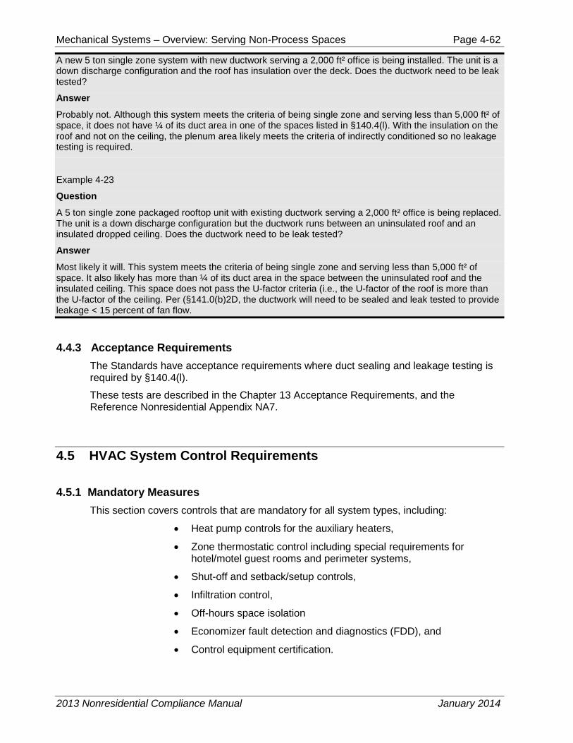
Fans 10%
Cooling 16%
Heating 2%
Indoor 33%
Office 2%
Outdoor 6%
Cooking 1%
Refrigeration 7%
Water 1%
Miscellaneous 22%
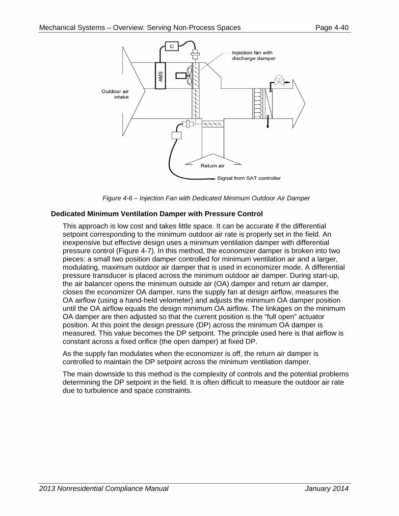
Figure 4-1 – Typical Nonresidential Building Electricity Use
Heating, cooling and ventilation account for about 28% of commercial building electricity use in California. Source IEQ RFP, December 2002, California Energy Commission No. 500-02-501.
2013 Nonresidential Compliance Manual January 2014
Mechanical Systems – Overview: Serving Non-Process Spaces Page 4-3
4.1.2 Mandatory Measures Mandatory measures §110.0-110.5 and §120.0-120.5 apply to all nonresidential buildings, whether the designer chooses the prescriptive or performance approach to compliance. Mandatory measures will be discussed further in the chapter and include:
1. Equipment certification and equipment efficiency §110.1 and §110.2.
2. Service water heating systems and equipment §110.3.
3. Spa and pool heating systems and equipment §110.4
4. Restrictions on pilot lights for natural gas appliances and equipment §110.5.
5. Ventilation requirements §120.1 including:
a. Natural ventilation
b. Mechanical ventilation, and
c. Demand controlled or occupant sensor controlled ventilation
6. Control requirements §120.2 including:
a. Zoning
b. Thermostats including Occupant Controlled Smart Thermostats (OCST)
c. Shut-off controls
d. Supply/Exhaust Damper Controls
e. Night setback/setup,
f. Area isolation
g. Demand shed controls, and
h. Automatic fault detection and diagnostics for air-side economizers.
7. Pipe insulation §120.3.
8. Duct construction and insulation §120.4.
9. Acceptance tests §120.5 and 2013 Nonresidential Appendix NA7.
4.1.3 Prescriptive and Performance Compliance Approaches After the mandatory measures are met, the Standards allow mechanical system compliance to be demonstrated through prescriptive or performance requirements.
A. Prescriptive Requirements Prescriptive measures cover items that can be used to qualify components and systems on an individual basis and are contained in §140.4. Prescriptive measures provide the basis of energy use for the Standards: You can comply with them directly in the prescriptive approach or provide an alternate design that meets a prescriptive Time Dependent Valuation (TDV) target in the performance approach. Prescriptive measures include:
1. Load calculations, sizing, system type and equipment selection §140.4(a) and (b).
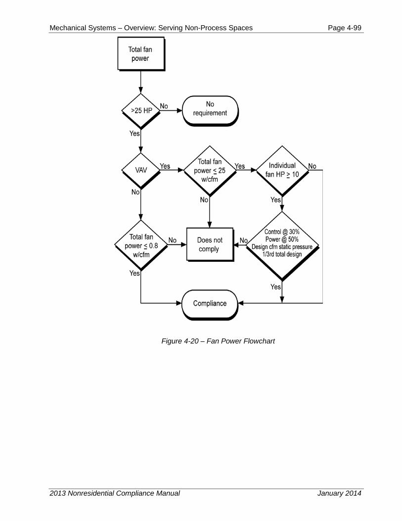
2. Fan power consumption §140.4(c).
2013 Nonresidential Compliance Manual January 2014
Mechanical Systems – Overview: Serving Non-Process Spaces Page 4-4
3. Controls to reduce reheating, recooling and mixing of conditioned air streams; §140.4(d).
4. Economizers §140.4(e).
5. Supply temperature reset §140.4(f).
6. Restrictions on electric-resistance heating §140.4(g).
7. Fan speed controls for heat rejection equipment §140.4(h).
8. Limitation on centrifugal fan cooling towers §140.4(h).
9. Minimum chiller efficiency §140.4(i)
10. Limitation on air-cooled chillers §140.4(j).
11. Hydronic system design §140.4(k).
12. Duct sealing §140.4(l).
13. Supply fan control §140.4(m)
B. Performance Approach The Performance Approach §140.1 allows the designer to trade off energy use in different building systems. This approach provides greater design flexibility but requires extra effort to perform: a computer simulation of the building must be developed to show compliance. In this approach the design team must still meet all of the mandatory measures but they do not have to meet specific prescriptive measures. Performance approach trade-offs can be across all of the disciplines (mechanical, lighting, envelope, and Covered Processes). The performance approach creates two models: 1) a base-case building energy model which meets all of the mandatory and prescriptive requirements; and 2) a proposed building energy model that reflects the proposed building design. The design complies if the proposed design model has a lower TDV value than the base-case model. The performance approach requires the use of an Energy Commission-certified compliance software program, and may only be used to model the performance of mechanical systems that are covered under the building permit application (see Section 4.8 and Chapter 11 for more detail).
4.2 Equipment Requirements With the exception of chillers as described in Section 4.2.2 below, all of the equipment efficiency requirements are mandatory measures.
The mandatory requirements for mechanical equipment must be included in the system design, whether compliance is shown by the prescriptive or the performance approach. These features have been shown to be cost effective over a wide range of building types and mechanical systems.
It is worth noting that most mandatory features for equipment efficiency are requirements for the manufacturer. It is the responsibility of the designer, however, to specify products in the building design that meet these requirements. Manufacturers of central air conditioners and heat pumps, room A/C, package terminal A/C, package terminal heat pumps, spot air conditioners, computer room air conditioners, central fan-type furnaces, gas space heaters, boilers, pool heaters and water heaters are regulated through the Title 20 Appliance Efficiency Regulations. Manufacturers must certify to the Energy
2013 Nonresidential Compliance Manual January 2014
Mechanical Systems – Overview: Serving Non-Process Spaces Page 4-5
Commission that their equipment meets or exceeds minimum standards. The Energy Commission maintains a database which lists the certified equipment and can be found at:
Additionally, manufacturers of low leakage air-handling units must certify to the Energy Commission that the air-handler unit meets the specifications in Reference Joint Appendix JA9.
4.2.1 Mechanical equipment subject to the mandatory requirements must:
A. Be certified by the manufacturer as complying with the efficiency requirements as prescribed in Sections:
§110.1 Mandatory Requirements for Appliances
§110.2 Mandatory Requirements for Space Conditioning Equipment
(a) Efficiency
(d) Gas- and Oil-Fired Furnace Standby Loss Controls
(f) Low Leakage Air-Handling Units
§110.3 Mandatory Requirements for Service Water Heating Systems and Equipment
(a) Certification by Manufactures, and
(b) Efficiency
§110.4 Mandatory Requirements for Pool and Spa Systems and Equipment
(a) Certification by Manufactures
§110.5 Natural Gas Central Furnaces, Cooking Equipment, and Pool and Spa Heaters: Pilot Lights Prohibited
B. Be specified and installed in accordance with Sections:
§110.2 Mandatory Requirements for Space Conditioning Equipment
(b) Controls for Heat Pumps with Supplementary Electric Resistance Heaters
(c) Thermostats
(e) Open and Closed Circuit Cooling Towers (blowdown control)
§110.3 Mandatory Requirements for Service Water Heating Systems and Equipment
(c) Installation
§120.1 Requirements for Ventilation
§120.2 Required Controls for Space Conditioning Systems including Occupant Controlled Smart Thermostats (OCST)
§120.3 Requirements for Pipe Insulation
§120.4 Requirements for Air Distribution Ducts and Plenums
§120.5 Required Nonresidential Mechanical System Acceptance
2013 Nonresidential Compliance Manual January 2014
Mechanical Systems – Overview: Serving Non-Process Spaces Page 4-6
4.2.2 Equipment Efficiency §110.2(a)
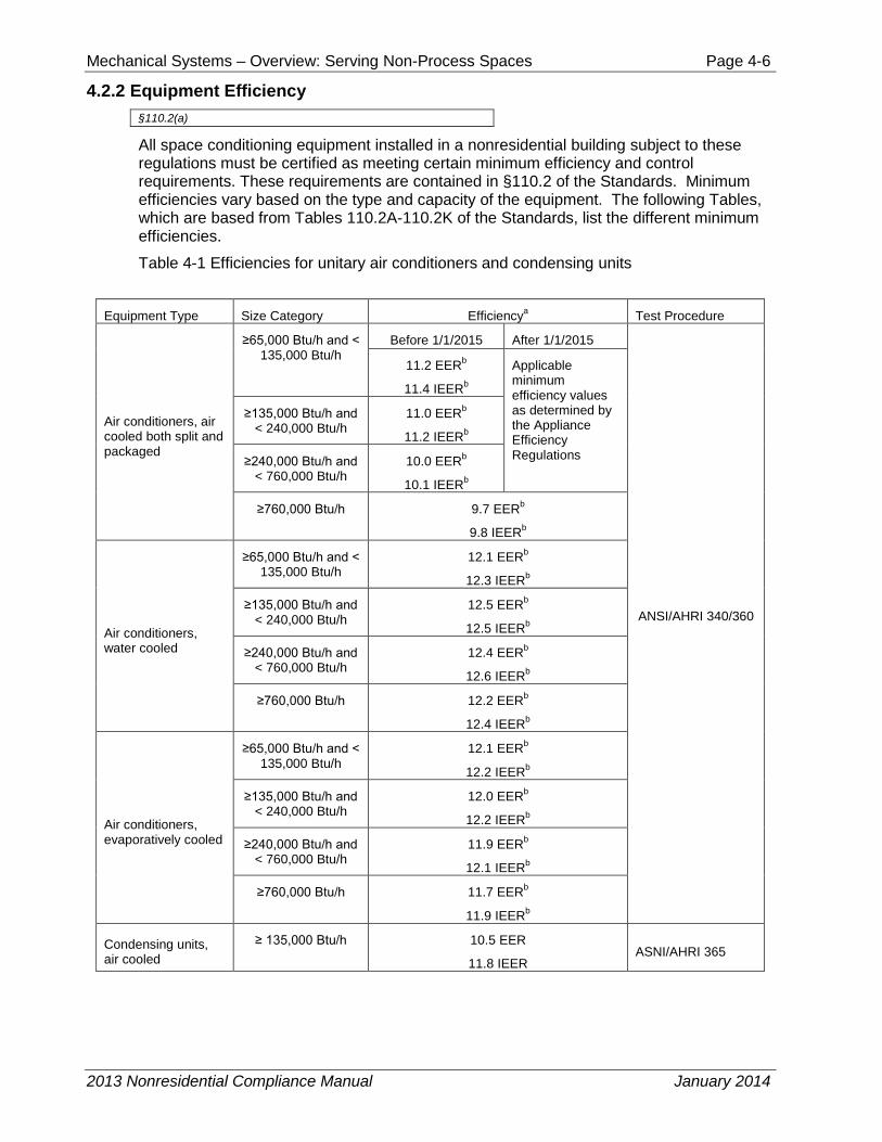
All space conditioning equipment installed in a nonresidential building subject to these regulations must be certified as meeting certain minimum efficiency and control requirements. These requirements are contained in §110.2 of the Standards. Minimum efficiencies vary based on the type and capacity of the equipment. The following Tables, which are based from Tables 110.2A-110.2K of the Standards, list the different minimum efficiencies.
Table 4-1 Efficiencies for unitary air conditioners and condensing units
Equipment Type Size Category Efficiencya Test Procedure
Air conditioners, air cooled both split and packaged
≥65,000 Btu/h and < 135,000 Btu/h
Before 1/1/2015 After 1/1/2015
ANSI/AHRI 340/360
11.2 EERb
11.4 IEERb
Applicable minimum efficiency values as determined by the Appliance Efficiency Regulations
≥135,000 Btu/h and < 240,000 Btu/h
11.0 EERb
11.2 IEERb
≥240,000 Btu/h and < 760,000 Btu/h
10.0 EERb
10.1 IEERb
≥760,000 Btu/h 9.7 EERb
9.8 IEERb
Air conditioners, water cooled
≥65,000 Btu/h and < 135,000 Btu/h
12.1 EERb
12.3 IEERb
≥135,000 Btu/h and < 240,000 Btu/h
12.5 EERb
12.5 IEERb
≥240,000 Btu/h and < 760,000 Btu/h
12.4 EERb
12.6 IEERb
≥760,000 Btu/h 12.2 EERb
12.4 IEERb
Air conditioners, evaporatively cooled
≥65,000 Btu/h and < 135,000 Btu/h
12.1 EERb
12.2 IEERb
≥135,000 Btu/h and < 240,000 Btu/h
12.0 EERb
12.2 IEERb
≥240,000 Btu/h and < 760,000 Btu/h
11.9 EERb
12.1 IEERb
≥760,000 Btu/h 11.7 EERb
11.9 IEERb
Condensing units, air cooled
≥ 135,000 Btu/h 10.5 EER
11.8 IEER ASNI/AHRI 365
2013 Nonresidential Compliance Manual January 2014
Mechanical Systems – Overview: Serving Non-Process Spaces Page 4-7
(Cont.) Table 4-1 Efficiencies for unitary air conditioners and condensing units Equipment Type Size Category Efficiencya Test Procedure
Condensing units, water cooled
≥ 135,000 Btu/h 13.5 EER
14.0 IEER
Condensing units, Evaporatively cooled
≥ 135,000 Btu/h 13.5 EER
14.0 IEER aIEERs are only applicable to equipment with capacity control as per ANSI/AHRI 340/360 TEST PROCEDURES bDeduct 0.2 from the required EERs and IEERs for units with a heating section other than electric resistance heat
Table 4-2 Unitary and Applied Heat Pumps
Equipment Type Size Category Subcategory or
Rating Condition Efficiencya Test Procedure
Air Cooled (cooling mode)
≥65,000 Btu/h and < 135,000 Btu/h
Split system and single package
11.0 EERb
11.2 IEERb
ANSI/AHRI 340/360
≥135,000 Btu/h and < 240,000 Btu/h
10.6 EERb
10.7 IEERb
≥240,000 Btu/h 9.5 EERb
9.6 IEERb
Water source (cooling mode)
≥65,000 Btu/h and < 135,000 Btu/h
860F entering water
12.0 EER
Groundwater source (cooling mode)
< 135,000 Btu/h 590F entering water
16.2 EER
Ground source (cooling mode)
< 135,000 Btu/h 770F entering water
13.4 EER
Water source water-to-water (cooling)
< 135,000 Btu/h 770F entering water
10.0 EER
Groundwater source water-to-water
< 135,000 Btu/h 590F entering water
16.3 EER
Ground source brint-to-water (cooling mode)
< 135,000 Btu/h 770F entering water
12.1 EER
Air Cooled (Heating Mode) Split system and single package
≥65,000 Btu/h and < 135,000 Btu/h (cooling capacity)
470F db/430F wb outdoor air
3.3 COP
170F db/150F wb outdoor air
2.25 COP
≥135,000 Btu/h (cooling capacity)
470F db/430F wb outdoor air
3.2 COP
170F db/150F wb outdoor air
2.05 COP
2013 Nonresidential Compliance Manual January 2014
Mechanical Systems – Overview: Serving Non-Process Spaces Page 4-8
Equipment Type Size Category Subcategory or
Rating Condition Efficiencya Test Procedure
Water source (heating mode)
< 135,000 Btu/h (cooling capacity)
680F entering water 4.2 COP ISO-13256-1
Groundwater source (heating mode)
< 135,000 Btu/h (cooling capacity)
500F entering water 3.6 COP ISO-13256-1
Ground source (heating mode)
< 135,000 Btu/h (cooling capacity)
320F entering water 3.1 COP ISO-13256-1
Water source water-to-water (heating mode)
< 135,000 Btu/h (cooling capacity)
680F entering water 3.7 COP ISO-13256-2
Groundwater source water-to-water (heating mode)
< 135,000 Btu/h (cooling capacity)
500F entering water 3.1 COP ISO-13256-2
Ground source brine-to-water (heating mode)
< 135,000 Btu/h (cooling capacity)
320F entering water 2.5 COP ISO-13256-2
aIEERs are applicable to equipment as per ANSI/AHRI 340/360 test procedures. bDeduct 0.2 from the required EERs and IEERs for units with a heating section other than electric resistance heat
Table 4-3 Air Cooled Gas Engine Heat Pumps
Equipment Type Size Category Subcategory or
Rating Condition Efficiency Test Procedurea
Air-cooled gas-engine heat pump
(cooling mode) All Capacities 950F db Outdoor
air 0.60 COP ANSI Z21.40.4A
Air-cooled gas-engine heat pump (Heating mode)
All Capacities 470F db/430F wb Outdoor air 0.720 COP ANSI Z21.40.4A
aApplicable test procedure and reference year are provided under the definitions
2013 Nonresidential Compliance Manual January 2014
Mechanical Systems – Overview: Serving Non-Process Spaces Page 4-9
Table 4-4 Water Chilling Packages Minimum Efficiency
Equipment Type Size Category Path A
Efficiency a,b Path B
Efficiency a,b Test Procedure
Air Cooled, with condenser
Electrically Operated
< 150 tons ≥ 9.562 EER
≥ 12.5 IPLV NA
AHRI 550/590
≥ 150 tons ≥ 9.562 EER
≥ 12.75 IPLV NA
Air Cooled, without condenser
Electrically Operated
All Capacities Air-cooled chillers without condensers must be rated with matching condensers and comply with the air-cooled chiller efficiency requirements.
Water Cooled, Electrically Operated, Reciprocating
All Capacities Reciprocating units must comply with the water-cooled positive displacement efficiency requirements.
Water Cooled, Electrically Operated Positive Displacement
< 75 tons ≤ 0.780 kW/ton
≤ 0.630 IPLV
≤ 0.800 kW/ton
≤ 0.600 IPLV
≥ 75 tons and < 150 tons
≤ 0.775 kW/ton
≤ 0.615 IPLV
≤ 0.790 kW/ton
≤ 0.586 IPLV
≥ 150 tons and < 300 tons
≤ 0.680 kW/ton
≤ 0.580 IPLV
≤ 0.718 kW/ton
≤ 0.540 IPLV
≥ 300 tons ≤ 0.620 kW/ton
≤ 0.540 IPLV
≤ 0.639 kW/ton
≤ 0.490 IPLV
Water Cooled, Electrically Operated, Centrifugal
< 150 tons ≤ 0.634 kW/ton
≤ 0.596 IPLV
≤ 0.639 kW/ton
≤ 0.450 IPLV
≥ 150 tons and < 300 tons
≤ 0.634 kW/ton
≤ 0.596 IPLV
≤ 0.639 kW/ton
≤ 0.450 IPLV
≥ 300 tons and < 600 tons
≤ 0.576 kW/ton
≤ 0.549 IPLV
≤ 0.600 kW/ton
≤ 0.400 IPLV
≥ 600 tons ≤ 0.570 kW/ton
≤ 0.539 IPLV
≤ 0.590 kW/ton
≤ 0.400 IPLV
2013 Nonresidential Compliance Manual January 2014
Mechanical Systems – Overview: Serving Non-Process Spaces Page 4-10
(Cont.) Table 4-4 Water Chilling Packages Minimum Efficiency
Equipment Type Size Category Path A
Efficiency a,b Path B
Efficiency a,b Test Procedure
Air Cooled Absorption, Single Effect
All Capacities ≥ 0.60 COP NA
ANSI/AHRI 560
Water Cooled Absorption, Single Effect
All Capacities ≥ 0.70 COP NA
Absorption Double Effect, Indirect-Fired
All Capacities ≥ 1.00 COP
≥ 1.05 IPLV NA
Absorption Double Effect, Direct-Fired
All Capacities ≥ 1.00 COP
≥ 1.00 IPLV NA
Water Cooled Gas Engine Driven Chiller
All Capacities ≥ 1.20 COP
≥ 2.00 IPLV NA ANSI Z21.40.4A
a No requirements for:
• Centrifugal chillers with design leaving evaporator temperature < 360F; or • Positive displacement chillers with designed leaving fluid temperatures ≤ 320F; or • Absorption chillers with design leaving fluid temperature < 400F
b Must meet the minimum requirements of Path A or Path B. However, both the full load (COP) and IPLV must be met to fulfill the requirements of the applicable Path.
Table 4-5 Packaged Terminal Air Conditioners and Heat Pumps
Equipment Type Size Category
(Input)
Subcategory or Rating
Condition
Efficiency Test
Procedurec Before 10/08/2012
After 10/08/2012
PTAC (cooling mode) newly constructed or newly conditioned or additions
All Capacities 950F db Outdoor air
12.5-(0.213 x Cap/1000)a x EER
13.8-(0.300 x Cap/1000)a x EER
ANSI/AHRI/CSA 310/380
PTAC (cooling mode) Replacementsb
All Capacities 950F db Outdoor air
10.9-(0.213 x Cap/1000)a x EER
10.9-(0.213 x Cap/1000)a x EER
PTHP (cooling mode) Newly constructed or newly conditioned or additions
All Capacities 950F db Outdoor air
12.3-(0.213 x Cap/1000)a x EER
14.0-(0.300 x Cap/1000)a x EER
PTHP (Cooling mode) Replacementsb
All Capacities 950F db Outdoor air
10.8-(0.213 x Cap/1000)a x EER
10.8-(0.213 x Cap/1000)a x EER
2013 Nonresidential Compliance Manual January 2014
Mechanical Systems – Overview: Serving Non-Process Spaces Page 4-11
(Cont.) Table 4-5 Packaged Terminal Air Conditioners and Heat Pumps
Equipment Type Size Category
(Input)
Subcategory or Rating
Condition Efficiency Equipment
Type Size Category
(Input)
PTHP (Heating mode) Newly constructed or newly conditioned or additions
All Capacities 3.2-(0.026 x Cap/1000)a x COP
3.7-(0.052 x Cap/1000)a x COP
PTHP (Heating mode) Replacementsb
All Capacities 2.9-(0.026 x Cap/1000)a x COP
2.9-(0.026 x Cap/1000)a x COP
SPVAC (Cooling mode)
< 65,000 Btu/h
950F db/750F wb Outdoor air 9.0 EER 9.0 EER
ANSI/AHRI 390
≥ 65,000 Btu/h and < 135,000 Btu/h
950F db/750F wb Outdoor air 8.9 EER 9.0 EER
≥ 135,000 Btu/h and < 240,000 Btu/h
950F db/750F wb Outdoor air 8.6 EER 9.0 EER
SPVHP (Cooling mode)
< 65,000 Btu/h
950F db/750F wb Outdoor air 9.0 EER 9.0 EER
≥ 65,000 Btu/h and < 135,000 Btu/h
950F db/750F wb Outdoor air 8.9 EER 9.0 EER
≥ 135,000 Btu/h and < 240,000 Btu/h
950F db/750F wb Outdoor air 8.6 EER 9.0 EER
SPVHP (Heating mode)
< 65,000 Btu/h
470F db/430F wb Outdoor air 3.0 COP 3.0 COP
≥ 65,000 Btu/h and < 135,000 Btu/h
470F db/430F wb Outdoor air 3.0 COP 3.0 COP
≥ 135,000 Btu/h and < 240,000 Btu/h
470F db/430F wb Outdoor air 2.9 COP 2.9 COP
aCap means the rated cooling capacity of the product in Btu/h. If the unit’s capacity is less than 7000 Btu/h, use 7000 Btu/h in the calculation. If the unit’s capacity is greater than 15,000 Btu/h, use 15,000 Btu/h in the calculation. bReplacement units must be factory labeled as follows: “Manufactured for replacement applications only; not to be installed in newly constructed buildings.” Replacement efficiencies apply only to units with existing sleeves less than 16 inches high or less than 42 inch wide and having a cross-sectional area less than 670 sq. in. cApplicable test procedure and reference year are provided under the definitions
2013 Nonresidential Compliance Manual January 2014
Mechanical Systems – Overview: Serving Non-Process Spaces Page 4-12
Table 4-6 Heat Transfer Equipment Equipment Type Subcategory Minimum Efficiencya Test Procedureb
Liquid-to-liquid heat exchangers
Plate type NR ANSI/AHRI 400
aNR = no requirement b Applicable test procedure and reference year are provided under the definitions
Table 4-7 Performance Requirements for Heat Rejection Equipment
Equipment Type
Total System Heat Rejection
Capacity at Rated Conditions
Subcategory or Rating Condition
Performance Required, a, b, c, d Test Proceduree
Propeller or axial fan Open-circuit cooling towers
All
950F entering water
850F leaving water
750F entering air wb
≥ 42.1 gpm/hp CTI ATC-105 and CTI STD-201
Centrifugal fan open-circuit cooling towers
All
950F entering water
850F leaving water
750F entering air wb
≥ 20.0 gpm/hp CTI ATC-105 and CTI STD-201CTI
ATC
Propeller or axial fan closed-circuit cooling towers
All
1020F entering water
900F leaving water
750F entering air wb
≥ 14.0 gpm/hp CTI ATC-105S and CTI STD-201CTI ATC
Centrifugal fan closed-circuit cooling towers
All
1020F entering water
900F leaving water
750F entering air wb
≥ 7.0 gpm/hp CTI ATC-105S and CTI STD-201CTI ATC
Air cooled condensers All
1250F condensing temperature R22 test fluid
1900F entering gas temperature
150F subcooling
950F entering db
≥ 176,000 Btu/h∙hp ANSI/AHRI 460
2013 Nonresidential Compliance Manual January 2014
Mechanical Systems – Overview: Serving Non-Process Spaces Page 4-13
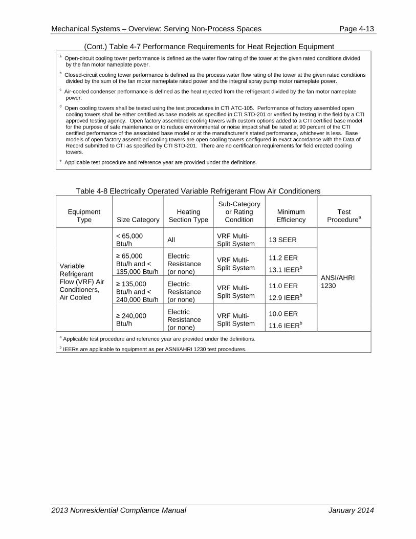
(Cont.) Table 4-7 Performance Requirements for Heat Rejection Equipment a Open-circuit cooling tower performance is defined as the water flow rating of the tower at the given rated conditions divided
by the fan motor nameplate power. b Closed-circuit cooling tower performance is defined as the process water flow rating of the tower at the given rated conditions
divided by the sum of the fan motor nameplate rated power and the integral spray pump motor nameplate power. c Air-cooled condenser performance is defined as the heat rejected from the refrigerant divided by the fan motor nameplate
power. d Open cooling towers shall be tested using the test procedures in CTI ATC-105. Performance of factory assembled open
cooling towers shall be either certified as base models as specified in CTI STD-201 or verified by testing in the field by a CTI approved testing agency. Open factory assembled cooling towers with custom options added to a CTI certified base model for the purpose of safe maintenance or to reduce environmental or noise impact shall be rated at 90 percent of the CTI certified performance of the associated base model or at the manufacturer’s stated performance, whichever is less. Base models of open factory assembled cooling towers are open cooling towers configured in exact accordance with the Data of Record submitted to CTI as specified by CTI STD-201. There are no certification requirements for field erected cooling towers.
e Applicable test procedure and reference year are provided under the definitions.
Table 4-8 Electrically Operated Variable Refrigerant Flow Air Conditioners
Equipment Type Size Category
Heating Section Type
Sub-Category or Rating Condition
Minimum Efficiency
Test Procedurea
Variable Refrigerant Flow (VRF) Air Conditioners, Air Cooled
< 65,000 Btu/h All VRF Multi-
Split System 13 SEER
ANSI/AHRI 1230
≥ 65,000 Btu/h and < 135,000 Btu/h
Electric Resistance (or none)
VRF Multi-Split System
11.2 EER
13.1 IEERb
≥ 135,000 Btu/h and < 240,000 Btu/h
Electric Resistance (or none)
VRF Multi-Split System
11.0 EER
12.9 IEERb
≥ 240,000 Btu/h
Electric Resistance (or none)
VRF Multi-Split System
10.0 EER
11.6 IEERb a Applicable test procedure and reference year are provided under the definitions. b IEERs are applicable to equipment as per ASNI/AHRI 1230 test procedures.
2013 Nonresidential Compliance Manual January 2014
Mechanical Systems – Overview: Serving Non-Process Spaces Page 4-14
Table 4-9 Electrically Operated VRF Air to Air and Applied Heat Pumps
Equipment Type Size Category
Heating Section Type
Sub-Category or Rating Condition
Minimum Efficiency
Test Procedureb
VRF Air Cooled, (cooling mode)
< 65,000 Btu/h
All VRF multi-split Systema 13 SEER AHRI 1230
≥ 65,000 Btu/h and < 135,000 Btu/h
Electric Resistance (or none)
VRF multi-split Systema
11.0 EER
12.9 IEERc
≥ 135,000 Btu/h and < 240,000
Electric Resistance (or none)
VRF multi-split Systema
10.6 EER
12.3 IEERc
≥ 240,000 Electric Resistance (or none)
VRF multi-split Systema
9.5 EER
11.0 IEERc
VRF Water source (cooling mode)
< 65,000 Btu/h
All VRF multi-split Systema
860F entering water
12.0 EER
AHRI 1230
≥ 65,000 Btu/h and < 135,000 Btu/h
All VRF multi-split Systema
860F entering water
12.0 EER
≥ 135,000 Btu/h
All VRF multi-split systema
860F entering water
10.0 EER
VRF Groundwater source (cooling mode)
≥ 135,000 Btu/h
All VRF multi-split systema
590F entering water
16.2 EER
AHRI 1230 ≥ 135,000 Btu/h
All VRF multi-split systema
590F entering water
13.8 EER
VRF Ground source (cooling mode)
≥ 135,000 Btu/h
All VRF multi-split systema
770F entering water
13.4 EER
AHRI 1230 ≥ 135,000 Btu/h
All VRF multi-split systema
770F entering water
11.0 EER
2013 Nonresidential Compliance Manual January 2014
Mechanical Systems – Overview: Serving Non-Process Spaces Page 4-15
(Cont.) Table 4-9 Electrically Operated VRF Air to Air and Applied Heat Pumps VRF Air cooled (heating mode)
< 65,000 Btu/h (cooling capacity)
VRF multi-split system 7.7 HSPF
AHRI 1230
≥ 65,000 Btu/h and < 135,000 Btu/h (cooling capacity)
VRF multi-split system
470F db/ 430F wb outdoor air
3.3 COP
VRF multi-split system
170F db/ 150F wb outdoor air
2.25 COP
≥ 135,000 Btu/h (cooling capacity)
VRF multi-split system
470F db/ 430F wb outdoor air
3.2 COP
VRF multi-split system
170F db/ 150F wb outdoor air
2.05 COP
VRF Water source (heating mode)
< 135,000 Btu/h (cooling capacity)
VRF multi-split system 680F entering water
4.2 COP
AHRI 1230 ≥ 135,000 Btu/h (cooling capacity)
VRF multi-split system 680F entering water
3.9 COP
VRF Groundwater source
< 135,000 Btu/h (cooling capacity)
VRF multi-split system 500F entering water
3.6 COP
AHRI 1230 ≥ 135,000 Btu/h (cooling capacity)
VRF multi-split system 500F entering water
3.3 COP
VRF Ground source (heating mode)
< 135,000 Btu/h (cooling capacity)
VRF multi-split system 320F entering water
3.1 COP
AHRI 1230 ≥ 135,000 Btu/h (cooling capacity)
VRF multi-split system 320F entering water
2.8 COP
a Deduct 0.2 from the required EERs and IEERs for VRF multi-split system units with a heating recovery section.
b Applicable test procedure and reference year are provided under the definitions.
c IEERs are applicable to equipment as per ANSI/AHRI 1230 test procedures.
2013 Nonresidential Compliance Manual January 2014
Mechanical Systems – Overview: Serving Non-Process Spaces Page 4-16
Table 4-10 Warm-Air Furnaces and Combination Warm-Air Furnaces/Air-Conditioning Units, Warm-Air Duct Furnaces, and Unit Heaters
Equipment Type Size Category
(Input) Subcategory or
Rating Condition Minimum Efficiency Test Procedurea
Warm-Air Furnace, Gas-Fired < 225,000 Btu/h Maximum
Capacitiyb 78% AFUE or
80% Et
DOE 10 CFR Part 430 or Section 2.39, Thermal Efficiency, ANSI Z21.47
≥ 225,00 Btu/h Maximum Capacitiyb 80% Et
Section 2.39, Thermal Efficiency, ANSI Z21.47
Warm-Air Furnace, Oil-Fired < 225,000 Btu/h Maximum
Capacitiyb 78% AFUE or
80% Et
DOE 10 CFR Part 430 or Section 42, Combustion, UL 727
≥ 225,000 Btu/h Maximum Capacitiyb 80% Et
Section 42, Combustion, UL 727
Warm-Air Duct Furnaces, Gas-Fired
All Capacities Maximum Capacitiyb 80% Ec
Section 2.10, Efficiency, ANSI Z83.8
Warm-Air Unit Heaters, Gas-Fired
All Capacities Maximum Capacitiyb 80% Ec
Section 2.10, Efficiency, ANSI Z83.8
Warm-Air Unit Heaters, Oil-Fired All Capacities Maximum
Capacitiyb 80% Ec Section 40, Combustion, UL 731
a Applicable test procedure and reference year are provided under the definitions.
b Compliance of multiple firing rate units shall be at maximum firing rate.
Et = thermal efficiency, units must also include an interrupted or intermittent ignition device (IID), have jacket losses not exceeding 0.75 percent of the input rating, and have either power venting or a flue damper. A vent damper is an acceptable alternative to a flue damper for those furnaces where combustion air is drawn from the conditioned space.
Ec = combustion efficiency (100% less flue losses). See test procedure for detailed discussion.
1. As of August 8, 2008, according to the Energy Policy Act of 2005, units must also include interrupted or intermittent ignition device (IID) and have either power venting or an automatic flue damper.
2. Combustion units not covered by NAECA (3-phase power or cooling capacity greater than or equal to 19 kW) may comply with either rating.
2013 Nonresidential Compliance Manual January 2014
Mechanical Systems – Overview: Serving Non-Process Spaces Page 4-17
Table 4-11 Gas and Oil Fired Boilers
Equipment Type Sub Category Size Category
(Input) Minimum
Efficiencyb,c Test Procedurea
Boiler, hot water
Gas Fired
< 300,000 Btu/h 80% AFUE DOE 10 CFR Part 430
≥ 300,000 Btu/h and < 2,500,000
Btu/hd 80% Et DOE 10 CFR Part
431
≥ 2,500,000 Btu/he 82% Et
Oil Fired
< 300,000 Btu/h 80% AFUE DOE 10 CFR Part 430
≥ 300,000 Btu/h and < 2,500,000
Btu/hd 80% Et
DOE 10 CFR Part 431
≥ 2,500,000 Btu/he 82% Et
Boiler, steam
Gas Fired < 300,000 Btu/h 75% AFUE DOE 10 CFR Part 430
Gas Fired – all, except natural draft
≥ 300,000 Btu/h and < 2,500,000
Btu/hd 79% Et
DOE 10 CFR Part 431
≥ 2,500,000 Btu/he 79% Et
DOE 10 CFR Part 431
Gas Fired, natural draft
≥ 300,000 Btu/h and < 2,500,000
Btu/hd 77% Et
DOE 10 CFR Part 431
≥ 2,500,000 Btu/he 77% Et
DOE 10 CFR Part 431
< 300,000 Btu/h 80% AFUE DOE 10 CFR Part 430
≥ 300,000 Btu/h and < 2,500,000
Btu/hd 81% Et
DOE 10 CFR Part 431
≥ 2,500,000 Btu/he 81% Et
DOE 10 CFR Part 431
a Applicable test procedure and reference year are provided under the definitions.
b Ec = combustion efficiency (100% less flue losses). See reference document for detail information
c Et = thermal efficiency. See test procedure for detailed information.
d Maximum capacity – minimum and maximum ratings as provided for and allowed by the unit’s controls.
e Included oil-fired (residual).
2013 Nonresidential Compliance Manual January 2014
Mechanical Systems – Overview: Serving Non-Process Spaces Page 4-18
In the above tables, where more than one efficiency standard or test method is listed, the requirements of both shall apply. For example, unitary air-cooled air conditioners have an EER requirement for full-load operation and an IEER for part-load operation. The air conditioner must have both a rated EER and IEER equal to or higher than that specified in the Standards at the specified Air-Conditioning, Heating, and Refrigeration Institute (AHRI) standard rating conditions Similarly, where equipment can serve more than one function, such as both heating and cooling, or space heating and water heating, it must comply with the efficiency standards applicable to each function.
Where a requirement is for equipment rated at its “maximum rated capacity” or “minimum rated capacity,” the capacity shall be as provided for and allowed by the controls during steady state operation. For example, a boiler with high/low firing must meet the efficiency requirements when operating at both its maximum capacity and minimum capacity.
Exceptions exist to the listed minimum efficiency for specific equipment, the first being water-cooled centrifugal water-chilling packages that are not designed for operation at ANSI/AHRI Standard 550/590 test conditions of 44°F leaving chilled water temperature and 85°F entering condenser water temperature with 3 gallons per minute per ton condenser water flow shall have a minimum maximum full load COP kW/ton and NPLV ratings adjusted using the following equation:
• Adjusted maximum full-load kW/ton rating = full load (kW/ton) rating from Table 110.2D/Kadj
• Adjusted maximum NPLV rating (kW/ton) = IPLV ( kW/ton) rating from Table 110.2D/Kadj
Where:
Kadj = (A) x ( B)
A = (0.00000014592 x (LIFT)4) – (0.0000346496 x (LIFT)3 )+ (0.00314196 x (LIFT)2) – (0.147199 x *(LIFT)) + 3.9302
LIFT = LvgCond – LvgEvap (°F)
LvgCond = Full-load leaving condenser fluid temperature (°F)
LvgEvap = Full-load leaving evaporator fluid temperature (°F)
B = (0.0015 x LvgEvap) + 0.934
The adjusted full-load and NPLV values are only applicable for centrifugal chillers meeting all of the following full-load design ranges:
• Maximum Leaving Condenser Fluid Temperature: 115°F
• LIFT ≥ 20°F and ≤ 80°F
Centrifugal chillers designed to operate outside of these ranges are not covered by this exception and therefore have no minimum efficiency requirements.
The other exception is for positive displacement (air- and water-cooled) chillers with a leaving evaporator fluid temperature higher than 32°F, shall show compliance with Table 4-3 when tested or certified with water at standard rating conditions, per the referenced test procedure.
2013 Nonresidential Compliance Manual January 2014
Mechanical Systems – Overview: Serving Non-Process Spaces Page 4-19
4.2.3 Equipment not covered by the Appliance Efficiency Regulations is regulated by §110.2 and §110.3. To comply, equipment specified in the plans and specifications must meet the minimum standards mandated in that section. Manufacturers of equipment not regulated by the Appliance Efficiency Regulations are not required to certify their equipment to the Energy Commission; it is the responsibility of the designer and contractor to specify and install equipment that complies.
To verify certification, use one of the following options:
A. The Energy Commission’s website includes listings of energy efficient appliances for several appliance types. The website address is: https://cacertappliances.energy.ca.gov/Pages/ApplianceSearch.aspx. The Energy Commission’s Hotline staff can provide further assistance 1-800-772-3300 or (916) 654-5106 if not found on the website.
B. The complete appliance database can be downloaded. This requires spreadsheet programs compatible with Microsoft EXCEL. To use the data, a user must download the database file (or files), download a brand file and a manufacturer file and then decompress the files. Next, the user will need to download a description file that provides details on what is contained in each of the data fields. With these files, and using database software, the data can be sorted and manipulated.
C. The Air Conditioning, Heating and Refrigeration Institute (AHRI) Directory of Certified Products can be used to verify certification of air-conditioning equipment. This is available on their website at www.ahrinet.org.
4.2.4 Controls for Heat Pumps with Supplementary Electric Resistance Heaters §110.2(b)
The Standards discourages the use of electric resistance heating when an alternative method of heating is available. In the case of a heat pump, these systems may contain electric resistance heat strips which act as a supplemental heating source. If this system is to be used then controls must be put in place that limits the use of the electric resistance to not operate when the heating load can be satisfied with the heat pump alone. This includes the requirement that the thermostat must be able to provide step up controls that will incrementally adjust the indoor temperature setting so that the heat pump can gradually raise the temperature until the final desired indoor temperature is reached. Also, the controls must set a “cut-on” temperature for compressor heating which is higher than the “cut-on” temperature for electric resistance heating, and the “cut-off temperature for compression heating is higher than the “cut-off” temperature for electric resistance heating.
Several exceptions exist for this requirement; if the electric resistance heating is for defrost, star-ups and follows the room thermostat set points (or another control mechanism designed to preclude the unnecessary operation) or the heat pump is a room air-conditioner heat pump.
4.2.5 Thermostats §110.2(c) and §120.2(b)4
When a central energy management control system is not included in the design of the HVAC system, then a thermostat with setback capabilities must be installed. This
2013 Nonresidential Compliance Manual January 2014
Mechanical Systems – Overview: Serving Non-Process Spaces Page 4-20
requirement applies to all unitary heating or cooling systems, which includes heat pumps, to have a thermostat that is capable of at least 4 set points in a 24 hour period. In the case of a heat pump the control requirements of section 4.24 must also be met. In addition, per §120.2(b)4, all unitary single zone, air conditioners, heat pumps, and furnaces, the thermostat must comply with the requirements of Reference Joint Appendix JA5, also known as the Occupant Controlled Smart Thermostats, which are capable of receiving demand response signals in the event of grid congestion and shortages during high electrical demand periods.
There are two exceptions to 120.2(b)4 Occupant Controlled Smart Thermostats:
1. Systems serving zones that must have constant temperatures to protect a process or product (e.g. a laser laboratory or a museum).
2. The following HVAC systems do not need to comply with the setback thermostat requirement: a. Gravity gas wall heaters, b. Gravity floor heaters, c. Gravity room heaters, d. Non-central electric heaters, e. Fireplaces or decorative gas appliance, f. Wood stoves, g. Room air conditioners, h. Room heat pumps
4.2.6 Furnace Standby Loss Controls §110.2(d)
Forced air gas- and oil-fired furnaces with input ratings ≥225,000 Btu/h are required to have controls and designs that limit their standby losses:
A. They must have either an intermittent ignition or interrupted device (IID). Standing pilot lights are not allowed.
B. They must have either power venting or a flue damper. A vent damper is an acceptable alternative to a flue damper for furnaces where combustion air is drawn from the conditioned space.
Any furnace with an input rating ≥225,000 Btu/h that is not located within the conditioned space must have jacket losses not exceeding 0.75 percent of the input rating. This includes electric furnaces as well as fuel-fired units.
4.2.7 Open and Closed Circuit Cooling Towers §110.2 (e)
All open and closed circuit cooling towers with rated capacity of 150 tons or greater must have a control system that maximizes the cycles of concentration based on the water quality conditions based on either conductivity or flow. If the controls system is conductivity based then the system must automate bleed and chemical feed based on conductivity. The installation criteria for the conductivity controllers must be in accordance with the manufacturer’s specifications in order to maximize accuracy. If the control system if flow based, then the system must be automated in proportion to metered makeup volume, metered bleed volume, recirculating pump run time or bleed time.
2013 Nonresidential Compliance Manual January 2014
Mechanical Systems – Overview: Serving Non-Process Spaces Page 4-21
The makeup water line must be equipped with an analog flow meter that is either wired or wireless and an overflow alarm to prevent overflow of the sump in the event of water valve failure. The alarm system may send an audible signal or an alert through an EMCS (energy management control system).
Drift eliminators are of a louvered or comb like design that is installed at the top of the cooling tower to capture water particles that become entrained in the air stream. These drift eliminators are now required to achieve drift reduction to 0.002 percent of the circulated water volume for counter-flow towers and 0.005 percent for cross-flow towers.
Additionally, maximum achievable cycles of concentration must be documented based on local water supply (which is reported annually by the local utility) and Langelier Saturation Index (LSI) of 2.5 or less. A calculator that is approved by the Energy Commission must be used in this process and the compliance form must be reviewed and approved by the Professional Engineer (P.E.) of record.
4.2.8 Pilot Lights §110.5
Pilot lights are prohibited in:
C. Fan type central furnaces. This includes all space-conditioning equipment that distributes gas-heated air through duct work §110.5(a). This prohibition does not apply to radiant heaters, unit heaters, boilers or other equipment that does not use a fan to distribute heated air.
D. Household cooking appliances, unless the appliance does not have an electrical connection, and the pilot consumes less than 150 Btu/h §110.5(b).
E. Pool and spa heaters §110.5(c)(d).
Example 4-1
Question
If a 15 ton (180kBtuh) air-cooled packaged AC unit with a gas furnace rated at 260,000 Btu/h maximum heating capacity has an EER of 10.9, an IEER of 11.2 and a heating thermal efficiency of 78 percent, does it comply?
Answer
No. The cooling side complies because both the EER and IEER exceed the requirements of Table 4-1 (11.0-0.2=10.8 EER and 11.2-0.2=11.0 IEER for a 15 ton unit). The EER and IEER in this table are for units with electric heat. Footnote b reduces the required EER and IEER by 0.2 for units with heating sections other than electric resistance heat. With gas heat, an EER of 10.9 (>10.8) and an IEER of 11.2 (>11.0), this unit complies. Note that the 0.2 deduction provided in Tables 4-1 and 4-2 compensate for the higher fan power required to move air over the heat exchangers for fuel-fired heaters.
From Table 110.2-J, the heating efficiency must be at least 80 percent thermal efficiency. This unit has a 78percent thermal efficiency (<80%); therefore the unit does not comply.
2013 Nonresidential Compliance Manual January 2014
Mechanical Systems – Overview: Serving Non-Process Spaces Page 4-22
Example 4-2
Question
A 500,000 Btu/h gas-fired boiler with high/low firing has a full load combustion efficiency of 82 percent, 78 percent thermal efficiency and a low-fire combustion efficiency of 80 percent. Does the unit comply?
Answer
No. Per Table 110.2-K, the thermal efficiency must be greater than 80percent. This boiler’s thermal efficiency is 78percent (<80%) so it doesn’t comply.
Example 4-3
Question
A 300 ton centrifugal chiller is designed to operate at 44°F chilled water supply, 90°F condenser water return and 3 gpm/ton condenser water flow. What is the maximum allowable full load kW/ton and NPLV?
Answer
As the chiller is centrifugal and is designed to operate at a condition different from AHRI Standard 550/590 standard rating conditions, the appropriate efficiencies can be calculated using the Kadj equations in
§110.2(a). From Table 110.2-D (Equipment Type:Water Cooled, Electrically Operated, Centrifugal; Size Category: ≥ 300 tons and < 600 tons) this chiller at AHRI rating conditions has a maximum full load efficiency of 0.576 kW/ton and a maximum IPLV of 0.549 kW/ton for Path A and a maximum full load efficiency of 0.600 kW/ton and a maximum IPLV of 0.400 kW/ton for Path B.
The Kadj is calculated as follows:
LIFT = LvgCond – LvgEvap = 90F-44F = 46F
A = (0.00000014592 x (46)4) – (0.0000346496 x (46)3 )+ (0.00314196 x (46)2) – (0.147199 x *(46)) + 3.9302=1.08813
B = (0.0015 x 44) + 0.934 = 1.000
Kadj=A x B=1.08813
For compliance with Path A, the maximum Full load kW/ton = 0.576 / 1.08813 = 0.529 kW/ton and the maximum NPLV= 0.549 / 1.08813 = 0.505 kW/ton
For compliance with Path B the maximum Full load kW/ton = 0.600 / 1.08813 = 0.551 kW/ton and the maximum NPLV= 0.400 / 1.08813 = 0.388 kW/ton
To meet the mandatory measures §110.2 the chiller can comply with either the Path A or Path B requirement (footnote b in Table 110.2-D). To meet the prescriptive requirement §140.4(i) the chiller would have to meet or exceed the Path B requirement.
Example 4-4
Question
A 300 ton water cooled chiller with a screw compressor that serves a thermal energy storage system is designed to operate at 34°F chilled water supply, 82°F condenser water supply and 94°F condenser water return, does it have a minimum efficiency requirement and if so, what is the maximum full load kW/ton and NPLV?
Answer
As the chiller is positive displacement (screw and scroll compressors are positive displacement) and is designed to operate at a chilled water temperature above 32°F it does have a minimum efficiency requirement per Exception 2 to 110.2(a). From Table 110.2-D (Equipment Type: Water Cooled, Electrically Operated, Positive Displacement; Size Category: ≥ 300 tons) this chiller at AHRI rating conditions has a maximum full load efficiency of 0.620 kW/ton and a maximum IPLV of 0.540 kW/ton for Path A and a maximum full load efficiency of 0.639 kW/ton and a maximum IPLV of 0.490 kW/ton for Path B.
2013 Nonresidential Compliance Manual January 2014
Mechanical Systems – Overview: Serving Non-Process Spaces Page 4-23
The Kadj is calculated as follows:
LIFT = LvgCond – LvgEvap = 94F-34F = 60F A = (0.00000014592 x (60)4) – (0.0000346496 x (60)3 )+ (0.00314196 x (60)2) – (0.147199 x *(60)) + 3.9302=0.81613 B = (0.0015 x 34) + 0.934 = 0.98500 Kadj=A x B=0.80388 For compliance with Path A, the maximum Full load kW/ton = 0.620 / 0.80388 = 0.771 kW/ton and the maximum NPLV= 0.540 / 0.80388 = 0.672 kW/ton.For compliance with Path B the maximum Full load kW/ton = 0.639 / 0.80388 = 0.795 kW/ton and the maximum NPLV= 0.490 / 0.80388 = 0.610 kW/ton. To meet the mandatory measures §110.2 the chiller can comply with either the Path A or Path B requirement (footnote b in Table 110.2-D). To meet the prescriptive requirement §140.4(i) the chiller would have to meet or exceed the Path B requirement. Example 4-5
Question
Are all cooling towers required to be certified by CTI?
Answer No. Per footnote d in Standards Table 110.2-G, field-erected cooling towers are not required to be certified. Factory-assembled towers must either be CTI-certified or have their performance verified in a field test (using ATC 105) by a CTI-approved testing agency. Furthermore only base models need to be tested; options in the air-stream, like access platforms or sound traps, will derate the tower capacity by 90 percent of the capacity of the base model or the manufacturer’s stated performance, whichever is less.
Example 4-6
Question
Are there any mandatory requirements for a water-to-water plate-and-frame heat exchanger?
Answer
Yes, Table 110.2-F requires that it be rated per ANSI/AHRI 400. This standard ensures the accuracy of the ratings provided by the manufacturer.
4.2.9 Commercial Boilers §120.9
A commercial boiler is a type of boiler with a capacity (rated maximum input) of 300,000 Btu per hour (Btu/h) or more and serving a space heating or water heating load in a commercial building.
1. Combustion air positive shut-off shall be provided on all newly installed commercial boilers as follows:
A. All boilers with an input capacity of 2.5 MMBtu/h (2,500,000 Btu/h) and above, in which the boiler is designed to operate with a non-positive vent static pressure. This is sometimes referred to as natural draft or atmospheric boilers. Forced draft boilers, which rely on a fan to provide the appropriate amount of air into the combustion chamber, are exempt from this requirement.
B. All boilers where one stack serves two or more boilers with a total combined input capacity per stack of 2.5 MMBtu/h (2,500,000 Btu/h). This requirement applies to natural draft and forced draft boilers.
Combustion air positive shut-off is a means of restricting air flow through a boiler combustion chamber during standby periods, used to reduce standby heat loss. A
2013 Nonresidential Compliance Manual January 2014
Mechanical Systems – Overview: Serving Non-Process Spaces Page 4-24
flue damper and a vent damper are two examples of combustion air positive shut-off devices.
Installed dampers can be interlocked with the gas valve so that the damper closes and inhibits air flow through the heat transfer surfaces when the burner has cycled off, thus reducing standby losses. Natural draft boilers receive the most benefit from draft dampers because they have less resistance to airflow than forced draft boilers. Forced draft boilers rely on the driving force of the fan to push the combustion gases through an air path that has relatively higher resistance to flow than in a natural draft boiler. Positive shut-off on a forced draft boiler is most important on systems with a tall stack height or multiple boiler systems sharing a common stack.
2. Boiler combustion air fans with motors 10 horsepower or larger shall meet one of the following for newly installed boilers:
The fan motor shall be driven by a variable speed drive, or
The fan motor shall include controls that limit the fan motor demand to no more than 30 percent of the total design wattage at 50 percent of design air volume. Electricity savings result from run time at part-load conditions. As the boiler firing rate decreases, the combustion air fan speed can be decreased.
3. Newly installed boilers with an input capacity of 5 MMBtu/h (5,000,000 Btu/h) and greater shall maintain excess (stack-gas) oxygen concentrations at less than or equal to 5.0 percent by volume on a dry basis over firing rates of 20 percent to 100 percent. Combustion air volume shall be controlled with respect to firing rate or measured flue gas oxygen concentration. Use of a common gas and combustion air control linkage or jack shaft is prohibited. Boilers with steady state full-load thermal efficiency 85 percent or higher are exempt from this requirement.
One way to meet this requirement is with parallel position control. Boilers mix air with fuel (usually natural gas although sometimes diesel or oil) to supply oxygen during combustion. Stoichiometric combustion is the ideal air/fuel ratio where the mixing proportion is correct, the fuel is completely burned, and the oxygen is entirely consumed. Boilers operate most efficiently when the combustion air flow rate is slightly higher than the stoichiometric air-fuel ratio. However, common practice almost always relies on excess air to insure complete combustion, avoid unburned fuel and potential explosion, and prevent soot and smoke in the exhaust. Excess air has a penalty, which is increased stack heat loss and reduced combustion efficiency.
Parallel positioning controls optimize the combustion excess air to improve the combustion efficiency of the boiler. It includes individual servo motors allowing the fuel supply valve and the combustion air damper to operate independently of each other. This system relies on preset fuel mapping (i.e., a pre-programmed combustion curve) to establish proper air damper positions (as a function of the fuel valve position) throughout the full range of burner fire rate. Developing the combustion curve is a manual process, performed in the field with a flue-gas analyzer in the exhaust stack, determining the air damper positions as a function of
2013 Nonresidential Compliance Manual January 2014
Mechanical Systems – Overview: Serving Non-Process Spaces Page 4-25
the firing rate/fuel valve position. Depending on type of burner, a more consistent level of excess oxygen can be achieved with parallel position compared to single-point positioning control, since the combustion curve is developed at multiple points (firing rates), typically 10 to 25 points. Parallel positioning controls allow excess air to remain relatively low throughout a burner’s firing range. Maintaining low excess air levels at all firing rates provides significant fuel and cost savings while still maintaining a safe margin of excess air to insure complete combustion.
4.3 Ventilation Requirements §120.1
All of the ventilation requirements are mandatory measures. Some measures require acceptance testing, which is addressed in Section 4.3.12.
Within a building, all enclosed spaces that are normally used by humans must be continuously ventilated during occupied hours with outdoor air, using either natural or mechanical ventilation §120.1(a)1. An exception is provided to §120.1(a)1 for refrigerated warehouses or other buildings or spaces that are not normally used for human occupancy or work.
The standards allow for ventilation to use transfer air as long as it doesn’t have any “unusual sources of indoor air contaminants” and “the outdoor air that is supplied to all spaces combined, is sufficient to meet the requirements of Section 120.1(b)2 for each space individually ( see exception to §120.1(b)2). Good practice dictates that sources of contaminants be isolated and controlled with local exhaust. The designation and treatment of such spaces is subject to the designer’s discretion. Spaces needing special consideration include:
• Commercial and coin-operated dry cleaners • Bars and cocktail lounges • Smoking lounges and other designated smoking areas • Beauty and barbershops • Auto repair workshops • Print shops, graphic arts studios and other spaces where solvents are used in
a process • Copy rooms, laser printer rooms or other rooms where it is expected that
equipment may generate heavy concentrations of ozone or other contaminants • Blueprint machines
“Spaces normally used by humans” refers to spaces where people can be reasonably expected to remain for an extended period of time. Spaces where occupancy will be brief and intermittent, and that do not have any unusual sources of air contaminants, do not need to be directly ventilated. For example:
• A closet does not need to be ventilated, provided it is not normally occupied. • A storeroom that is only infrequently or briefly occupied does not require
ventilation. However, a storeroom that can be expected to be occupied for extended periods for clean-up or inventory must be ventilated, preferably with systems controlled by a local switch so that the ventilation system operates only when the space is occupied.
2013 Nonresidential Compliance Manual January 2014
Mechanical Systems – Overview: Serving Non-Process Spaces Page 4-26
“Continuously ventilated during occupied hours” implies that the design ventilation must be provided throughout the entire occupied period. This means that VAV systems must provide the code-required ventilation over their full range of operating supply airflow. Some means of dynamically controlling the minimum ventilation air must be provided.
4.3.1 Natural Ventilation §120.1(b)1
Natural outdoor ventilation may be provided for spaces where all normally occupied areas of the space are within a specific distance from an operable wall or roof opening through which outdoor air can flow. This distance is 20 ft. for most spaces and 25 ft. for hotel/motel guestrooms and high-rise residential spaces. The sum of the operable open areas must total at least 5 percent of the floor area of each space that is naturally ventilated. The openings must also be readily accessible to the occupants of the space at all times.
Airflow through the openings must come directly from the outdoors; air may not flow through any intermediate spaces such as other occupied spaces, unconditioned spaces, corridors, or atriums. High windows or operable skylights need to have a control mechanism accessible from the floor.
Example 4-7
Question
What is the window area required to ventilate a 30 ft. x 32 ft. classroom?
Answer
In order for all points to be within 20 ft. of an opening, windows must be distributed and run at least along two of the opposite walls. The area of the openings must be:
(32 ft. x 30 ft.) x 5 percent = 48 ft²
The actual window area must be at least 96 ft² if only half the window can be open at a time.
Calculations must be based on free area, taking into account framing and bug screens; the actual window area is approximately 100 ft² without bug screens and 110 ft² with bug screens.
Example 0-8
Question
Naturally ventilated classrooms are located on either side of a doubly-loaded corridor and transoms are provided between the classrooms and corridor. Can the corridor be naturally ventilated through the classrooms?
Answer
No. The corridor cannot be naturally ventilated through the classrooms and transom openings. The Standards require that naturally ventilated spaces have direct access to properly-sized openings to the outdoors. The corridor would require mechanical ventilation using either supply or exhaust fans.
2013 Nonresidential Compliance Manual January 2014
Mechanical Systems – Overview: Serving Non-Process Spaces Page 4-27
4.3.2 Mechanical Ventilation §120.1(b)2 and (d)
Mechanical outdoor ventilation must be provided for all spaces normally occupied that are not naturally ventilated. The Standards require that a space conditioning system provide outdoor air equal to or exceeding the ventilation rates required for each of the spaces that it serves. At the space, the required ventilation can be provided either directly through supply air or indirectly through transfer of air from the plenum or an adjacent space. The required minimum ventilation airflow at the space can be provided by an equal quantity of supply or transfer air. At the air-handling unit, the minimum outside air must be the sum of the ventilation requirements of each of the spaces that it serves. The designer may specify higher outside air ventilation rates based on the owner’s preference or specific ventilation needs associated with the space. However, specifying more ventilation air than the minimum allowable ventilation rates increases energy consumption and electrical peak demand and increases the costs of operating the HVAC equipment. Thus the designer should have a compelling reason to specify higher design minimum outside air rates than the calculated minimum outside air requirements in the Standards.
In the 2013 revision to the Standards the minimum OSA provided is required to be within 10 percent of the calculated minimum for both VAV and constant volume units.
A. In summary:
1. Ventilation compliance at the space is satisfied by providing supply and/or transfer air (exception to §120.1(b)2).
2. Ventilation compliance at the unit is satisfied by providing, at minimum, the outdoor air that represents the sum of the ventilation requirements at each space that it serves.
B. For each space requiring mechanical ventilation the ventilation rates must be the greater of either:
1. The conditioned floor area of the space, multiplied by the applicable minimum ventilation rate from the Standards in Table 120.1-A (2). This provides dilution for the building-borne contaminants like off-gassing of paints and carpets.
High-rise residential Ventilation Rates Specified by the CBC and CMC Hotel guest rooms (less than 500 ft²) 30 cfm/guest room Hotel guest rooms (500 ft² or greater) 0.15 Retail stores 0.20 All Others 0.15
2013 Nonresidential Compliance Manual January 2014
Mechanical Systems – Overview: Serving Non-Process Spaces Page 4-28
2. 15 cfm per person, multiplied by the expected number of occupants. For spaces with fixed seating (such as a theater or auditorium), the expected number of occupants is the number of fixed seats. For spaces without fixed seating, the expected number of occupants is assumed to be no less than one-half that determined for egress purposes in the California Building Code (CBC). The Standards specify the minimum outdoor ventilation rate to which the system must be designed. If desired, the designer may, with documentation, elect to provide more ventilation air. For example, the design outdoor ventilation rate may be determined using the procedures described in ASHRAE 62, provided the resulting outdoor air quantities are no less than required by the Standards.
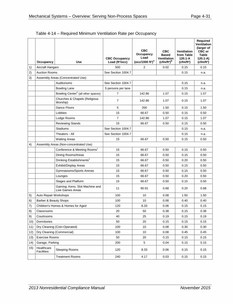
Table 4-13 shows the typical maximum occupant loads for various building uses (upon which minimum ventilation calculations are based). This provides dilution for the occupant-borne contaminants (or bio effluents) like body odor and germs.
Table 4-14 summarizes the combination of these two rates for typical spaces.
As previously stated, each space-conditioning system must provide outdoor ventilation air as follows.
1. For a space-conditioning system serving a single space, the required system outdoor airflow is equal to the design outdoor ventilation rate of the space.
2. For a space-conditioning system serving multiple spaces, the required outdoor air quantity delivered by the space-conditioning system must be not less than the sum of the required outdoor ventilation rate to each space. The Standards do not require that each space actually receive its calculated outdoor air quantity (§120.1(b)2 Exception). Instead, the actual supply to any given space may be any combination of recirculated air, outdoor air, or air transferred directly from other spaces, provided:
a. The total amount of outdoor air delivered by the space-conditioning system(s) to all spaces is at least as large as the sum of the space design quantities
b. Each space always receives a supply airflow, including recirculated air and/or transfer air, no less than the calculated outdoor ventilation rate
c. When using transfer air, none of the spaces from which air is transferred has any unusual sources of contaminants
2013 Nonresidential Compliance Manual November 2015
Mechanical Systems – Overview: Serving Non-Process Spaces Page 4-29
Table 4-13 – CBC Occupant Densities (ft² /person) Source Table 1004.1.2 of the California Building Code
Bowling lanes (including 15 feet of approach) 5 person per lane
Business areas 100 gross
Courtrooms – other than fixed seating areas 40 net
Day care 35 net
Dormitories 50 gross
Educational
Classroom area 20 net
Shops and other vocational room areas 50 net
Exercise rooms 50 gross
H-5 Fabrication and manufacturing areas 200 gross
Industrial areas 100 gross
Institutional areas
Inpatient treatment areas 240 gross
Outpatient areas 100 gross
Sleeping areas 120 gross
Kitchens, commercial 200 gross
Library
Reading rooms 50 net
Stack area 100 gross
Locker Rooms 50 gross
Mercantile
Area on other floors 60 gross
Basement and grade floor areas 30 gross
Storage, stock, shipping areas 300 gross
Parking garages 200 gross
2013 Nonresidential Compliance Manual November 2015
Mechanical Systems – Overview: Serving Non-Process Spaces Page 4-30
Residential 200 gross
Skating rinks, swimming pools
Rink and pool 50 gross
Decks 15 gross
Stages and platforms 15 net
Warehouses 500 gross
C. Where: Floor Area, Gross. The floor area within the inside perimeter of the exterior walls of the building under consideration, exclusive of vent shafts and courts, without deduction for corridors, stairways, closets, the thickness of interior walls, columns or other features. The floor area of a building, or portion thereof, not provided with surrounding exterior walls shall be the usable area under the horizontal projection of the roof or floor above. The gross floor area shall not include shafts with no openings or interior courts.
Floor Area, Net. The actual occupied area not including unoccupied accessory areas such as corridors, stairways, toilet rooms, mechanical rooms and closets.
2013 Nonresidential Compliance Manual November 2015
Mechanical Systems – Overview: Serving Non-Process Spaces Page 4-31
Table 4-14 – Required Minimum Ventilation Rate per Occupancy
Occupancy Use CBC Occupancy
Load (ft²/occ)
CBC Occupancy
Load (occ/1000 ft²)A
CBC Based
Ventilation (cfm/ft²)B
Ventilation from Table
120.1-A (cfm/ft²)
Required Ventilation (larger of CBC or Table
120.1-A) (cfm/ft²)
1) Aircraft Hangars 500 2 0.02 0.15 0.15
2) Auction Rooms See Section 1004.7 0.15 n.a.
3) Assembly Areas (Concentrated Use)
Auditoriums See Section 1004.7 0.15 n.a.
Bowling Lane 5 persons per lane 0.15 n.a.
Bowling Center5 (all other spaces) 7 142.86 1.07 0.15 1.07
30) All Others -- Including Unknown, Corridors, Restrooms, & Support Areas Commercial & Industrial Work
100 10 0.08 0.15 0.15
Footnotes: Equations: 1. Includes Convention & Civic Meeting Areas. 2. Bars, Cocktail & Smoking Lounges, Casinos. 3. Guestrooms less than 500 ft² use 30 cfm/guestroom. 4. High-rise Residential - for habitable areas not ventilated
with Natural Ventilation, cfm=(0.06 cfm/ft² + 5 cfm/occ). Default occupancy for dwelling units shall be two persons for studio and one-bedroom units, with one additional person for each additional bedroom.
5. Bowling centers, allow 5 persons for each lane including 15 feet of approach.
A. CBC Occupancy Load Equation:
𝑁𝑢𝑚𝑏𝑒𝑟 𝑜𝑓 𝑜𝑐𝑐𝑢𝑝𝑎𝑛𝑡𝑠 1000𝑓𝑡2⁄ =1000
𝑓𝑡2 𝑜𝑐𝑐𝑢𝑝𝑎𝑛𝑡⁄
B. CBC Based Ventilation Equation:
𝑐𝑓𝑚 𝑓𝑡2⁄ = 15 𝑐𝑓𝑚 × �𝑂𝑐𝑐𝑢𝑝𝑎𝑛𝑡𝑠 1000 𝑓𝑡2⁄
2 �
1000
2013 Nonresidential Compliance Manual November 2015
Mechanical Systems – Overview: Serving Non-Process Spaces Page 4-33
Example 4-9
Question
Ventilation for a two-room building:
Consider a building with two spaces, each having an area of 1,000 ft². One space is used for general administrative functions, and the other is used for classroom training. It is estimated that the office will contain 7 people, and the classroom will contain 50 (fixed seating). What are the required outdoor ventilation rates?
Answer
1. For the office area, the design outdoor ventilation air is the larger of:
7 people x 15 cfm/person = 105 cfm; or
1,000 ft² x 0.15 cfm/ft² = 150 cfm
For this space, the design ventilation rate is 150 cfm.
2. For the classroom, the design outdoor ventilation air is the larger of:
50 people x 15 cfm/person = 750 cfm; or
1,000 ft² x 0.15 cfm/ft² = 150 cfm
For this space the design ventilation rate is 750 cfm.
Assume the total supply air necessary to satisfy cooling loads is 1,000 cfm for the office and 1,500 cfm for the classroom. If each space is served by a separate system, then the required outdoor ventilation rate of each system is 150 cfm and 750 cfm, respectively. This corresponds to a 15 percent outside air (OA) fraction in the office HVAC unit, and 50 percent in the classroom unit.
If both spaces are served by a central system, then the total supply will be (1,000 + 1,500) cfm = 2500 cfm. The required outdoor ventilation rate is (150 + 750) = 900 cfm total. The actual outdoor air ventilation rate for each space is:
Office OA = 900 cfm x (1,000 cfm / 2,500 cfm) = 360 cfm
Classroom OA = 900 cfm x (1,500 cfm / 2,500 cfm) = 540 cfm
While this simplistic analysis suggests that the actual OA cfm to the classroom is less than design (540 cfm vs. 750 cfm), the analysis does not take credit for the dilution effect of the air recirculated from the office. The office is over-ventilated (360 cfm vs. 150 cfm) so the concentration of pollutants in the office return air is low enough that it can be used, along with the 540 cfm of outdoor air, to dilute pollutants in the classroom. The Standards allow this design provided that the system always delivers at least 750 cfm to the classroom (including transfer or recirculated air), and that any transfer air is free of unusual contaminants.
4.3.3 Direct Air Transfer The Standards allow air to be directly transferred from other spaces in order to meet a part of the ventilation supply to a space, provided the total outdoor quantity required by all spaces served by the building’s ventilation system is supplied by the mechanical systems. This method can be used for any space, but is particularly applicable to conference rooms, toilet rooms, and other rooms that have high ventilation requirements. Transfer air must be free from any unusual contaminants, and as such should not be taken directly from rooms where such sources of contaminants are anticipated. It is typically taken from the return plenum or directly from an adjacent space.
2013 Nonresidential Compliance Manual January 2014
Mechanical Systems – Overview: Serving Non-Process Spaces Page 4-34
Air may be transferred using any method that ensures a positive airflow. Examples include dedicated transfer fans, exhaust fans and fan-powered VAV boxes. A system having a ducted return may be balanced so that air naturally transfers into the space. Exhaust fans serving the space may discharge directly outdoors, or into a return plenum. Transfer systems should be designed to minimize recirculation of transfer air back into the space; duct work should be arranged to separate the transfer air intake and return points.
When each space in a two-space building is served by a separate constant volume system, the calculation and application of ventilation rate is straightforward, and each space will always receive its design outdoor air quantity. However, a central system serving both spaces does not deliver the design outdoor air quantity to each space. Instead, one space receives more than its allotted share, and the other less. This is because the training room has a higher design outdoor ventilation rate and/or a lower cooling load relative to the other space.
4.3.4 Distribution of Outdoor Air to Zonal Units §120.1(d)
When a return plenum is used to distribute outside air to a zonal heating or cooling unit, the outside air supply must be connected either:
Within 5 ft. of the unit; or
Within 15 ft. of the unit, with the air directed substantially toward the unit, and with a discharge velocity of at least 500 ft. per minute.
Water source heat pumps and fan coils are the most common application of this configuration. The unit fans should be controlled to run continuously during occupancy in order for the ventilation air to be circulated to the occupied space.
A central space-conditioning system(s) augmented by a few zonal units for spot conditioning may use transfer air from spaces served by the central system. A direct source of outdoor air is not required for each zonal unit. Similarly, transfer air may be used in buildings having central interior space-conditioning systems with outdoor air, and zonal units on the perimeter (without outdoor air).
While not required, the Standards recommend that sources of unusual contaminants be controlled through the use of containment systems that capture the contaminants and discharge them directly outdoors. Such systems may include exhaust hoods, fume hoods, small space exhausts and differential pressure control between spaces. The designer is advised to consult ASHRAE standards or other publications for guidance in this subject.
4.3.5 Ventilation System Operation and Controls §120.1(c)
Outdoor Ventilation Air and VAV Systems Except for systems employing Energy Commission-certified demand controlled ventilation (DCV) devices or space occupancy sensors, the Standards require that the minimum rate of outdoor air calculated per §120.1(b)2 be provided to each space at all times when the space is normally occupied §120.1(c)1. For spaces served by variable air volume (VAV) systems, this means that the minimum supply setting of each VAV box should be no less than the design outdoor ventilation rate calculated for the space, unless transfer air is
2013 Nonresidential Compliance Manual January 2014
Mechanical Systems – Overview: Serving Non-Process Spaces Page 4-35
used. If transfer air is used, the minimum box position, plus the transfer air, must meet the minimum ventilation rate. If transfer air is not used, the box must be controlled so that the minimum required airflow is maintained at all times (unless demand controlled ventilation or occupant sensor are employed).
The design outdoor ventilation rate at the system level must always be maintained when the space is occupied, even when the fan has modulated to its minimum capacity §120.1(c)1. Section 4.3.12 describes mandated acceptance test requirements for outside air ventilation in VAV air handling systems. In these tests, the minimum outside air in VAV systems will be measured both at full flow and with all boxes at minimum position.
Figure 4-2 shows a typical VAV system. In standard practice, the testing and balancing (TAB) contractor sets the minimum position setting for the outdoor air damper during construction. It is set under the conditions of design airflow for the system, and remains in the same position throughout the full range of system operation. Does this meet code? The answer is no. As the system airflow drops, so will the pressure in the mixed air plenum. A fixed position on the minimum outdoor air damper will produce a varying outdoor airflow. As depicted in Figure 4-2, this effect will be approximately linear (in other words, outdoor air airflow will drop directly in proportion to the supply airflow).
The following paragraphs present several methods used to dynamically control the minimum outdoor air in VAV systems, which are described in detail below.
Regardless of how the minimum ventilation is controlled, care should be taken to reduce the amount of outdoor air provided when the system is operating during the weekend or after hours with only a fraction of the zones active. §120.2(g) requires provision of “isolation zones” of 25,000 ft² or less. This can be provided by having the VAV boxes return to fully closed when their associated zone is in unoccupied mode. When a space or group of spaces is returned to occupied mode (e.g. through off-hour scheduling or a janitor’s override), only the boxes serving those zones need to be active. During this partial occupancy the ventilation air can be reduced to the requirements of those zones that are active. If all zones are of the same occupancy type (e.g. private offices), simply assign a floor area to each isolation zone and prorate the minimum ventilation area by the ratio of the sum of the floor areas presently active divided by the sum of all the floor areas served by the HVAC system.
Figure 4-2– VAV Reheat System with a Fixed Minimum Outdoor Air Damper Setpoint
2013 Nonresidential Compliance Manual January 2014
Mechanical Systems – Overview: Serving Non-Process Spaces Page 4-36
Fixed Minimum Damper Setpoint This method does not comply with the Standards; the airflow at a fixed minimum damper position will vary with the pressure in the mixed air plenum (see Figure 4-2Error! Reference source not found.). It is explicitly prohibited in 120.1(e)2.
Dual Minimum Setpoint Design This method complies with the Standards. An inexpensive enhancement to the fixed damper setpoint design is the dual minimum setpoint design, commonly used on some packaged AC units. The minimum damper position is set proportionally based on fan speed or airflow between a setpoint determined when the fan is at full speed (or airflow) and minimum speed (or airflow). This method complies with the letter of the Standards but is not accurate over the entire range of airflow rates and when there are wind or stack effect pressure fluctuations. But with DDC, this design has very low costs.
Energy Balance Method The energy balance method (Figure 4-3) uses temperature sensors in the outside, as well as return and mixed air plenums to determine the percentage of outdoor air in the supply air stream. The outdoor airflow is then calculated using the equations shown in Figure 4-3. This method requires an airflow monitoring station on the supply fan.
While technically feasible, it may be difficult to meet the outside air acceptance requirements with this approach because:
1. It is difficult to accurately measure the mixed air temperature, which is critical to the success of this strategy. Even with an averaging type bulb, most mixing plenums have some stratification or horizontal separation between the outside and mixed airstreams.1
2. Even with the best installation, high accuracy sensors, and field calibration of the sensors, the equation for percent outdoor air will become inaccurate as the return air temperature approaches the outdoor air temperature. When they are equal, this equation predicts an infinite percentage outdoor air.
3. The accuracy of the airflow monitoring station is likely to be low at low supply airflows.
4. The denominator of the calculation amplifies sensor inaccuracy as the return air temperature approaches the outdoor air temperature.
1 This was the subject of ASHRAE Research Project 1045-RP, “Verifying Mixed Air Damper Temperature and Air Mixing Characteristics.” Unless the return is over the outdoor air there are significant problems with stratification or airstream separation in mixing plenums.
2013 Nonresidential Compliance Manual January 2014
Mechanical Systems – Overview: Serving Non-Process Spaces Page 4-37
Figure 4-3 – Energy Balance Method of Controlling Minimum Outdoor Air
Return Fan Tracking This method is also technically feasible, but will likely not meet the acceptance requirements because the cumulative error of the two airflow measurements can be large, particularly at low supply/return airflow rates. It only works theoretically when the minimum outdoor air rate equals the rate of air required to maintain building pressurization (the difference between supply air and return air rates). Return fan tracking (Figure 4-4) uses airflow monitoring stations on both the supply and return fans. The theory behind this is that the difference between the supply and return fans has to be made up by outdoor air, and controlling the flow of return air forces more ventilation into the building. Several problems occur with this method:
1. The relative accuracy of airflow monitoring stations is poor, particularly at low airflows;
2. The cost of airflow monitoring stations;
3. It will cause building pressurization problems unless the ventilation air is equal to the desired building exfiltration plus the building exhaust.
ASHRAE research has also demonstrated that in some cases this arrangement can cause outdoor air to be drawn into the system through the exhaust dampers due to negative pressures at the return fan discharge.
2013 Nonresidential Compliance Manual January 2014
Mechanical Systems – Overview: Serving Non-Process Spaces Page 4-38
Figure 4-4 – Return Fan Tracking
Airflow Measurement of the Entire Outdoor Air Inlet Again, this method is technically feasible but will likely not meet the acceptance requirements depending on the airflow measurement technology. Most airflow sensors will not be accurate to a 5 to 15 percent turndown (the normal commercial ventilation range). Controlling the outdoor air damper by direct measurement with an airflow monitoring station (Figure 4-5Figure 4-) can be an unreliable method. Its success relies on the turndown accuracy of the airflow monitoring station. Depending on the loads in a building, the ventilation airflow can be between 5 and 15 percent of the design airflow. If the outdoor airflow sensor is sized for the design flow for the airside economizer, this method has to have an airflow monitoring station that can turn down to the minimum ventilation flow (between 5 and 15 percent). Of the different types available, only a hot-wire anemometer array is likely to have this low-flow accuracy while traditional pitot arrays will not. One advantage of this approach is that it provides outdoor airflow readings under all operating conditions, not just when on minimum outdoor air. For highest accuracy, provide a damper and outdoor air sensor for the minimum ventilation air that is separate from the economizer outdoor air intake.
2013 Nonresidential Compliance Manual January 2014
Mechanical Systems – Overview: Serving Non-Process Spaces Page 4-39
Figure 4-5 – Airflow Measurement of 100% Outdoor Air
Injection Fan Method This method complies with the Standards, but it is expensive and may require additional space. Note that an airflow sensor and damper are required since fan airflow rate will vary as mixed air plenum pressure varies. The injection fan method (Figure 4-6) uses a separate outdoor air inlet and fan sized for the minimum ventilation airflow. This inlet contains an airflow monitoring station, and a fan with capacity control (e.g., discharge damper; VFD), which is modulated as required to achieve the desired ventilation rate. The discharge damper is recommended since a damper must be provided anyway to shut off the intake when the AHU is off, and also to prevent excess outdoor air intake when the mixed air plenum is very negative under peak conditions. (The fan is operating against a negative differential pressure and thus cannot stop flow just by slowing or stopping the fan.) This method works, but the cost is high and often requires additional space for the injection fan assembly.
2013 Nonresidential Compliance Manual January 2014
Mechanical Systems – Overview: Serving Non-Process Spaces Page 4-40
Figure 4-6 – Injection Fan with Dedicated Minimum Outdoor Air Damper
Dedicated Minimum Ventilation Damper with Pressure Control This approach is low cost and takes little space. It can be accurate if the differential setpoint corresponding to the minimum outdoor air rate is properly set in the field. An inexpensive but effective design uses a minimum ventilation damper with differential pressure control (Figure 4-7). In this method, the economizer damper is broken into two pieces: a small two position damper controlled for minimum ventilation air and a larger, modulating, maximum outdoor air damper that is used in economizer mode. A differential pressure transducer is placed across the minimum outdoor air damper. During start-up, the air balancer opens the minimum outside air (OA) damper and return air damper, closes the economizer OA damper, runs the supply fan at design airflow, measures the OA airflow (using a hand-held velometer) and adjusts the minimum OA damper position until the OA airflow equals the design minimum OA airflow. The linkages on the minimum OA damper are then adjusted so that the current position is the “full open” actuator position. At this point the design pressure (DP) across the minimum OA damper is measured. This value becomes the DP setpoint. The principle used here is that airflow is constant across a fixed orifice (the open damper) at fixed DP.
As the supply fan modulates when the economizer is off, the return air damper is controlled to maintain the DP setpoint across the minimum ventilation damper.
The main downside to this method is the complexity of controls and the potential problems determining the DP setpoint in the field. It is often difficult to measure the outdoor air rate due to turbulence and space constraints.
2013 Nonresidential Compliance Manual January 2014
Mechanical Systems – Overview: Serving Non-Process Spaces Page 4-41
Figure 4-7 – Minimum Outdoor Air Damper with Pressure Control
Example 4-10
Question
Minimum VAV cfm:
If the minimum required ventilation rate for a space is 150 cfm, what is the minimum allowed airflow for its VAV box when the design percentage of outdoor air in the supply is 20 percent?
Answer
The minimum allowed airflow may be as low as 150 cfm provided that enough outdoor air is supplied to all spaces combined to meet the requirements of §120.1(b)2 for each space individually.
4.3.6 Pre-Occupancy Purge §120.1(c)2
Since many indoor air pollutants are out-gassed from the building materials and furnishings, the Standards require that buildings having a scheduled operation be purged before occupancy §120.1(c)2. Immediately prior to occupancy, outdoor ventilation must be provided in an amount equal to the lesser of:
1. The minimum required ventilation rate for 1 hour; or
2. 3 complete air changes.
Either criteria can be used to comply with the Standards. Three complete air changes means an amount of ventilation air equal to 3 times the volume of the occupied space. This air may be introduced at any rate provided for and allowed by the system, so that the actual purge period may be less than an hour.
A pre-occupancy purge is not required for buildings or spaces that are not occupied on a scheduled basis, such as storage rooms. Also, a purge is not required for spaces provided with natural ventilation.
2013 Nonresidential Compliance Manual January 2014
Mechanical Systems – Overview: Serving Non-Process Spaces Page 4-42
Where pre-occupancy purge is required, it does not have to be coincident with morning warm-up (or cool-down). The simplest means to integrate the two controls is to simply schedule the system to be occupied one hour prior to the actual time of anticipated occupancy. This allows the optimal start, warm-up or pull-down routines to bring the spaces up to (or down to) desired temperatures before opening the outdoor air damper for ventilation. This will reduce the required system heating capacity and ensure that the spaces will be at the desired temperatures and fully purged at the start of occupancy.
Figure 4-8 – Pre-Occupancy Purge Flowchart
Example 4-11
Question
Purge Period:
What is the length of time required to purge a space 10 ft. high with an outdoor ventilation rate of 1.5 cfm/ft²?
Answer
For 3 air changes, each ft² of space must be provided with:
OA volume = 3 x 10 = 30 cf/ft²
At a rate of 1.5 cfm/ft², the time required is:
Time = 30 cf/ft² / 1.5 cfm/ft² = 20 minutes
Example 4-12
Question
Purge with Natural Ventilation:
2013 Nonresidential Compliance Manual January 2014
Mechanical Systems – Overview: Serving Non-Process Spaces Page 4-43
In a building with natural ventilation, do the windows need to be left open all night to accomplish a building purge?
Answer
No. A building purge is required only for buildings with mechanical ventilation systems.
Example 4-13
Question
Purge with Occupancy Timer:
How is a purge accomplished in a building without a regularly scheduled occupancy whose system operation is controlled by an occupancy sensor?
Answer
There is no purge requirement for this building. Note that occupancy sensors and manual timers can only be used to control ventilation systems in buildings that are intermittently occupied without a predictable schedule.
4.3.7 Demand Controlled Ventilation and Occupant Sensor Ventilation Control Devices §120.1(c)3 to 5
Demand controlled ventilation (DCV) systems reduce the amount of ventilation supply air in response to a measured level of carbon dioxide (CO2) in the breathing zone. The Standards only permit CO2 sensors for the purpose of meeting this requirement; VOC and so-called “IAQ” sensors are not approved as alternative devices to meet this requirement. The Standards only permit DCV systems to vary the ventilation component that corresponds to occupant bioeffluents (this is basis for the 15 cfm/person portion of the ventilation requirement). The purpose of CO2 sensors is to track occupancy in a space; however, there are many factors that must be considered when designing a DCV system. There is often a lag time in the detection of occupancy through the build-up of CO2. This lag time may be increased by any factors that affect mixing, such as short circuiting of supply air or inadequate air circulation, as well as sensor placement and sensor accuracy. Build-up of odors, bioeffluents, and other health concerns may also lag changes in occupancy; therefore, the designers must be careful to specify CO2 based DCV systems that are designed to provide adequate ventilation to the space by ensuring proper mixing, avoiding short circuiting, and proper placement and calibration of the sensors.
The Standards requires the use of DVC systems for spaces with all of the following characteristics:
1. Served by single zone units with any controls or multiple zone systems with Direct Digital Controls (DDC) to the zone level, and
2. Has a design occupancy of 40 ft²/person or smaller (for areas without fixed seating where the design density for egress purposes in the CBC is 40 ft²/person or smaller), and
3. Has an air economizer
2013 Nonresidential Compliance Manual January 2014
Mechanical Systems – Overview: Serving Non-Process Spaces Page 4-44
There are five exceptions to this requirement:
1. The following spaces are permitted to use DCV but are not required to: classrooms, call centers, office spaces served by multiple zone systems that are continuously occupied during normal business hours with occupant density greater than 25 people per 1000 ft² per §120.1(b)2B (Table 4-13 and Table 4-14 above), healthcare facilities and medical buildings, and public areas of social services buildings.
2. Where the space exhaust is greater than the required ventilation rate minus 0.2 cfm/ft².
3. DCV devices are not allowed in the following spaces: Spaces that have processes or operations that generate dusts, fumes, mists, vapors, or gases and are not provided with local exhaust ventilation, such as indoor operation of internal combustion engines or areas designated for unvented food service preparation, or beauty salons.
4. Spaces with an area of less than 150 ft², or a design occupancy of less than 10 people per §120.1(b)2B (Table 4-13 and Table 4-14 above).
5. Spaces less than 1500 ft² that comply with §120.1(c)5 - Occupant Sensor Ventilation Control Devices.
The spaces listed in Exception 1 are exempted either due to concerns about equipment maintenance practices (schools and public buildings) or concerns about high levels of pathogens (social service buildings, medical buildings, healthcare facilities and to some extent classrooms). The second exception relates to the fact that spaces with high exhaust requirements won’t be able to provide sufficient turndown to justify the cost of the DCV controls. An example of this is a restaurant seating area where the seating area air is used as make-up air for the kitchen hood exhaust. The third exception recognizes that some spaces may need additional ventilation due to contaminants that are not occupant borne. It addresses spaces like theater stages where theatrical fog may be used or movie theater lobbies where unvented popcorn machines may be emitting odors and vapors into the space in either case justifying the need for higher ventilation rates. DCV devices shall not be installed in spaces included in Exception 3. The fourth exception recognizes the fact that DCV devices may not be cost effective in small spaces such as a 15 ft x 10 ft conference room or spaces with only a few occupants at design conditions. The fifth exception allows an occupant sensor to reduce the amount of ventilation supply air in a vacant room.
Although not required, the Standards permit design professionals to apply DCV on any intermittently occupied spaces served by either single-zone or multiple-zone equipment. §120.1(b)2 requires a minimum of 15 CFM of outdoor air per person times the expected number of occupants; however, it must be noted that these are minimum ventilation levels and the designers may specify higher ventilation levels if there are health related concerns that warrant higher ventilation rates.
CO2 based DCV is based on two principles:
1. Several studies (Berg-Munch et al. 1986, Cain et al. 1983, Fanger 1983 and 1988, Iwashita et al. 1990, Rasmussen et al. 1985) concluded that about 15 cfm of outdoor air ventilation per person will control human body odor such that roughly
2013 Nonresidential Compliance Manual January 2014
Mechanical Systems – Overview: Serving Non-Process Spaces Page 4-45
80 percent of unadapted persons (visitors) will find the odor to be at an acceptable level. These studies are the basis of the 15 cfm/person rate required by these Standards and most building codes. This ventilation rate can be roughly equated to CO2 concentration using the following steady-state equation.
Where V is the ventilation rate per person, is the CO2 generation rate per person, Cin,ss is the steady-state value of the indoor CO2 concentration, and Cout is the outdoor concentration. At the rate of CO2 generated by adults at typical activity levels in offices, 15 cfm/person equates to a differential CO2 concentration (indoor minus outdoor) of approximately 700 ppm.
2. The same level of odor acceptability was found to occur at 700 ppm differential CO2 concentration even for spaces that were not at equilibrium (Berg-Munch et al. 1986, Fanger 1983, Rasmussen et al. 1985), and the correlation was not strongly dependent on the level of physical activity. This suggests that while CO2 concentration may not track the number of occupants when spaces are not at steady-state, it does track the concentration of bioeffluents that determine people’s perception of air quality. It also suggests that odorous bioeffluents are generated at approximately the same rate as CO2.
Hence as activity level and bioeffluent generation rate increases (in the equation above), the rate of outdoor air required to provide acceptable air quality (V) increases proportionally, resulting in the same differential CO2 concentration.
Note that CO2 concentration only tracks indoor contaminants that are generated by occupants themselves and, to a lesser extent, their activities. It will not track other pollutants, particularly volatile organic compounds (VOCs) that off-gas from furnishings and building materials. Hence, where permitted or required by the Standards, demand controlled ventilation systems cannot reduce the outdoor air ventilation rate below the floor rate listed in Standards Table 120.1-A (typically 0.15 cfm/ft²) during normally occupied times.
DCV systems save energy if the occupancy varies significantly over time. Hence they are most cost effective when applied to densely occupied spaces like auditoriums, conference rooms, lounges or theaters. Because DCV systems must maintain the floor ventilation rate listed in Standards Table 120.1-A, they will not be applicable to sparsely occupied buildings such as offices where the floor rate always exceeds the minimum rate required by the occupants (see Table 4-14).
Where DCV is employed (whether mandated or not) the controls must meet all of the following requirements:
1. Sensors must be provided in each room served by the system that has a design occupancy of 40 ft²/person or less, with no less than one sensor per 10,000 ft² of floor space. When a zone or a space is served by more than one sensor, signal from any sensor indicating that CO2 is near or at the setpoint within a space, must trigger an increase in ventilation to the space. This requirement ensures that the space is adequately ventilated in case a sensor malfunctions. Design professional should ensure that sensors are placed throughout a large space, so that all areas are monitored by a sensor.
( )V N
C Cin ss out
=−
,
N
2013 Nonresidential Compliance Manual January 2014
Mechanical Systems – Overview: Serving Non-Process Spaces Page 4-46
2. The CO2 sensors must be located in the breathing zone (between 3 and 6 ft. above the floor or at the anticipated height of the occupant’s head). Sensors in return air ducts are not allowed since they can result in under-ventilation due to CO2 measurement error caused by short-circuiting of supply air into return grilles and leakage of outdoor air (or return air from other spaces) into return air ducts.
3. The ventilation must be maintained that will result in a concentration of CO2 at or below 600 ppm above the ambient level. The ambient levels can either be assumed to be 400 ppm or dynamically measured by a sensor that is installed within four feet of the outdoor air intake. At 400 ppm outside CO2 concentration, the resulting DCV CO2 setpoint would be 1000 ppm. (Note that a 600 ppm differential is less than the 700 ppm that corresponds to the 15 cfm/person ventilation rate. This provides a margin of safety against sensor error, and because 1000 ppm CO2 is a commonly recognized guideline value and referenced in earlier versions of ASHRAE Standard 62.)
4. Regardless of the CO2 sensor’s reading, the system is not required to provide more than the minimum ventilation rate required by §120.1(b). This prevents a faulty sensor reading from causing a system to provide more than the code required ventilation for system without DCV control. This high limit can be implemented in the controls.
5. The system shall always provide a minimum ventilation of the sum of the Standards Table 120.1-A values for all rooms with DCV and §120.1(b)2 (Table 4-13 of this manual) for all other spaces served by the system. This is a low limit setting that must be implemented in the controls.
6. The CO2 sensors must be factory-certified to have an accuracy within plus or minus 75 ppm at 600 and 1000 ppm concentration when measured at sea level and 25°C (77°F), factory calibrated or calibrated at start-up, and certified by the manufacturer to require calibration no more frequently than once every 5 years. A number of manufacturers have “self-calibrating” sensors now that either adjust to ambient levels during unoccupied times or adjust to the decrease in sensor bulb output through use of dual sources or dual sensors. For all systems, the manufacturers of sensors must provide a document to installers that their sensors meet these requirements. The installer must make this certification information available to the builder, building inspectors and, if specific sensors are specified on the plans, to plan checkers.
7. When a sensor failure is detected, the system must provide a signal to reset the system to provide the minimum quantity of outside air levels required by §120.1(b)2 to the zone(s) serviced by the sensor at all times that the zone is occupied. This requirement ensures that the space is adequately ventilated in case a sensor malfunctions. A sensor that provides a high CO2 signal on sensor failure will comply with this requirement.
8. For systems that are equipped with DDC to the zone level, the CO2 sensor(s) reading for each zone must be displayed continuously, and recorded. The energy management control system (EMCS) may be used to display and record the sensors’ readings. The display(s) must be readily available to maintenance staff so they can monitor the systems performance.
2013 Nonresidential Compliance Manual January 2014
Mechanical Systems – Overview: Serving Non-Process Spaces Page 4-47
New in the 2013 version of the Standards is the use of occupant sensor ventilation control devices §120.1(c)5. These are mandated for multipurpose rooms less than 1000 ft2 ; classrooms over 750 ft2; and conference, convention, auditorium and meeting center rooms greater than 750 ft2 that do not have processes or operations that generate dusts, fumes, vapors or gasses(by reference to §120.2(e)3). They are also an alternate method of compliance for spaces mandated to have DCV that are less than 1,500 ft2 (Exception 5 to 120.1(c)3).
There are a few spaces where it appears that both DCV and occupant sensor ventilation controls are mandated (e.g. auditoriums greater than 750 ft2). Exception 1 to §120.1(c)5 exempts occupant sensor ventilation controls if DCV is implemented as required by §120.1(c)4.
Where occupant sensor ventilation control devices are employed (whether mandated or not) the controls must meet all of the following requirements:
A. Sensors must meet the requirements of §110.9(b)4 and shall have suitable coverage to detect occupants in the entire space.
B. Sensors that are used for lighting can be used for ventilation as well as long as the ventilation system is controlled directly from the occupant sensor and is not subject to lighting overrides.
C. If a terminal unit serves several enclosed spaces, each space shall have its own occupant sensor and all sensors must indicate lack of occupancy before the zone airflow is cut off.
D. The occupant sensor override shall be disabled during preoccupancy purge (i.e. the terminal unit and central ventilation shall be active regardless of occupant status).
E. Supply fans on systems with all zones provided with occupant sensor ventilation control devices can cycle off if all zones are vacant provided that minimum ventilation to all zones is provided as follows:
F. For spaces with a design occupant density greater than or equal to 25 people per 1000 ft² (40 square foot or less per person); 25 percent of the rate listed in Table 120.1-A: Minimum Ventilation Rates.
To implement the last provision the supply fan on the unit serving the zones would have to cycle on for at least 15 minutes of every hour with the outside air damper at or above minimum position.
Section 4.3.12 describes mandated acceptance test requirements for DCV and occupant sensor ventilation control systems.
Fan cycling per §120.1(c)5E
While §120.1(c)1 requires that ventilation be continuous during normally occupied hours when the space is usually occupied, Exception No. 2 allows the ventilation to be disrupted for not more than 30 minutes at a time. In this case the ventilation rate during the time the system is ventilating must be increased so the average rate over the hour is equal to the required rate.
It’s important to review any related ventilation and fan cycling requirements in Title 8, which is the Division of Occupational Safety and Health (Cal/OSHA) regulations. Section
2013 Nonresidential Compliance Manual January 2014
Mechanical Systems – Overview: Serving Non-Process Spaces Page 4-48
5142 specifies the operational requirements related to HVAC minimum ventilation. It states:
Operation:
1. The HVAC system shall be maintained and operated to provide at least the quantity of outdoor air required by the State Building Standards Code, Title 24, Part 2, California Administrative Code, in effect at the time the building permit was issued.
2. The HVAC system shall be operated continuously during working hours except:
A. During scheduled maintenance and emergency repairs;
B. During periods not exceeding a total of 90 hours per calendar year when a serving electric utility by contractual arrangement requests its customers to decrease electrical power demand; or
C. During periods for which the employer can demonstrate that the quantity of outdoor air supplied by non-mechanical means meets the outdoor air supply rate required by (a)(1) of this Section. The employer must have available a record of calculations and/or measurements substantiating that the required outdoor air supply rate is satisfied by infiltration and/or by a non-mechanically driven outdoor air supply system.
Title 8 Section 5142(a)(1) refers to Title 24, Part 2 (the California Building Code) for the minimum ventilation requirements. Section 1203 in the California Building Code specifies the ventilation requirements, but simply refers to the California Mechanical Code, which is Title 24, Part 4.
Chapter 4 in the California Mechanical Code specifies the ventilation requirements. Section 402.3 states, “The system shall operate so that all rooms and spaces are continuously provided with the required ventilation rate while occupied.” Section 403.5.1 states, “Ventilation systems shall be designed to be capable of providing the required ventilation rates in the breathing zone whenever the zones served by the system are occupied, including all full and part-load conditions.” The required ventilation rates are thus not required whenever the zones are unoccupied. This section affirms that ventilation fans may be turned off during unoccupied periods. In addition, Section 403.6 states, “The system shall be permitted to be designed to vary the design outdoor air intake flow or the space or zone airflow as operating conditions change.” This provides further validation to fan cycling as operating conditions change between occupied and unoccupied. A vacant zone has no workers present and is thus not subject to working hour’s requirements until the zone is actually occupied by a worker. Finally, Table 4-1 in Title 24, Part 4, states; “Ventilation air supply requirements for occupancies regulated by the California Energy Commission are found in the California Energy Code.” Thus, it refers to Title 24, Part 6 as the authority on ventilation.
Title 8 Section 5142(a)(2) states, “The HVAC system shall be operated continuously during working hours.” This regulation does not indicate that the airflow, cooling, or heating needs to be continuous. If the HVAC system is designed to maintain average ventilation with a fan cycling algorithm, and is active in that mode, providing average ventilation air as required during working hours, it is considered to be operating continuously per its mode and sequence. During unoccupied periods, the HVAC system is turned off except for setback and it no longer operates continuously. During the occupied period, occupant sensors or CO2 sensors in the space provide continuous monitoring and the sequence is operating, cycling the fan and dampers as needed to maintain the ventilation during the occupied period. The HVAC system is operating with
2013 Nonresidential Compliance Manual January 2014
Mechanical Systems – Overview: Serving Non-Process Spaces Page 4-49
the purpose of providing ventilation, heating, and cooling continuously during the working hours. The heater, air conditioner, fans, and dampers all cycle on and off subject to their system controls to meet the requirements during the working hours.
Exceptions A, B, and C to Title 8 Section 5142(a)(2) all refer to a complete system shutdown where the required ventilation is not maintained.
Example 4-14
Question
Does a single zone air-handling unit serving a 2,000 ft² auditorium with fixed seating for 240 people require demand controlled ventilation?
Answer
Yes if it has an air-side economizer. There are three tests for the requirement.
The first test is whether the design occupancy is 40 ft²/person or less. This space has 2,000 ft²/240 people or 8.3 ft² /person.
The second test is that the unit is single zone
The third is that it has an air-side economizer.
A single CO2 sensor could be used for this space provided it is certified by the manufacturer to cover 2,000 ft² of space. The sensor must be placed directly in the space.
Example 4-15
Question
If two separate units are used to condition the auditorium in the previous example, is demand controlled ventilation required?
Answer
Yes, if they each meet the three tests.
Example 4-16
Question
The 2,000 ft2 auditorium in the previous examples appears to require both demand controlled ventilation per §120.1(c)3 and occupant sensor ventilation control devices per §120.1(c)5? Is this the case?
Answer
No, Exception 1 to §120.1(c)5 exempts occupant sensor ventilation controls if implemented as required by §120.1(c)4. Only demand controlled ventilation is required.
Example 4-17
Question
If a central AHU supplies five zones of office space (with a design occupant density of 100 ft²/person and two zones with conference rooms (with a design occupant density of 35 ft²/person) is it required to have demand controlled ventilation and if so, on which zones?
Answer
2013 Nonresidential Compliance Manual January 2014
Mechanical Systems – Overview: Serving Non-Process Spaces Page 4-50
If the AHU has DDC controls to the zone and an airside economizer it is required to have DCV controls in both of the conference room zones.
The minimum OSA will be set for 0.15 cfm/ft² times the total area of all seven zones (the office and conference room zones) and the maximum required OSA does not need to exceed the sum of 0.15 cfm/ft² for the 5 office zones plus 15 cfm per person for the two conference rooms.
4.3.8 Fan Cycling While §120.1(c)1 requires that ventilation be continuous during normally occupied hours, Exception No. 2 allows the ventilation to be disrupted for not more than 30 minutes at a time. In this case the ventilation rate during the time the system is ventilating must be increased so the average rate over the hour is equal to the required rate.
This restriction limits the duty cycling of fans by energy management systems to not more than 30 minutes at a time. In addition, when a space-conditioning system that also provides ventilation is controlled by a thermostat incorporating a fan “On/Auto” switch, the switch should be set to the “On” position. Otherwise, during mild conditions, the fan may be off the majority of the time.
4.3.9 Variable Air Volume (VAV) Changeover Systems Some VAV systems provide conditioned supply air, either heated or cooled, through a single set of ducting. These systems are called VAV changeover systems or, perhaps more commonly, variable volume and temperature (VVT™) systems, named after a control system distributed by Carrier Corp. In the event that heating is needed in some spaces at the same time that cooling is needed in others, the system must alternate between supplying heated and cooled air. When the supply air is heated, for example, the spaces requiring cooling are isolated (cut off) by the VAV dampers and must wait until the system switches back to cooling mode. In the meantime, they are generally not supplied with ventilation air.
Systems of this type may not meet the ventilation requirements if improperly applied. Where changeover systems span multiple orientations the designer must make control provisions to ensure that no zone is shut off for more than 30 at a time and that ventilation rates are increased during the remaining time to compensate. Alternatively, minimum damper position or airflow setpoints can be set for each zone to maintain supply air rates, but this can result in temperature control problems since warm air will be supplied to spaces that require cooling, and vice versa. Changeover systems that are applied to a common building orientation (e.g., all east or all interior) are generally the most successful since zones will usually have similar loads, allowing minimum airflow rates to be maintained without causing temperature control problems.
4.3.10 Adjustment of Ventilation Rate §120.1(b) specifies the minimum required outdoor ventilation rate, but does not restrict the maximum. However, if the designer elects to have the space-conditioning system operate at a ventilation rate higher than the rate required by the Standards, then the Standards require that the space-conditioning system must be adjustable so that in the future the ventilation rate can be reduced to the amount required by the Standards or the rate required for make-up of exhaust systems that are required for a process, for control of odors, or for the removal of contaminants within the space §120.1(e).
2013 Nonresidential Compliance Manual January 2014
Mechanical Systems – Overview: Serving Non-Process Spaces Page 4-51
In other words, a system can be designed to supply higher than minimum outside air volumes provided dampers or fan speed can be adjusted to allow no more than the minimum volume if, at a later time, someone decides it is desirable. The Standards preclude a system designed for 100 percent outdoor air, with no provision for any return air, unless the supply air quantity can be adjusted to be equal to the designed minimum outdoor air volume. The intent is to prevent systems from being designed that will permanently over-ventilate spaces.
4.3.11 Miscellaneous Dampers §120.2(f)
Dampers should not be installed on combustion air intakes, or where prohibited by other provisions of law §120.2(f) Exception Nos. 3 & 4. If the designer elects to install dampers on shaft vents to help control stack-induced infiltration, the damper should be motorized and controlled to open in accordance with applicable fire codes.
4.3.12 Acceptance Requirements §120.5
The Standards have acceptance test requirements for:
• Ventilation quantities at design airflow for constant volume systems §120.5(a)1 and NA7.5.1.2.
• Ventilation quantities at design and minimum airflow for VAV systems §120.5(a)1 and NA7.5.1.1.
• Ventilation system time controls §120.5(a)2 and NA7.5.2.
• Demand controlled ventilation systems §120.5(a)5 and NA7.5.5.
These test requirements are described in Chapter 12 and the Reference Nonresidential Appendix NA7.5. They are described in brief in the following paragraphs.
Example 4-18
Question
Maintenance of Ventilation System:
In addition to these commissioning requirements for the ventilation system, are there any periodic requirements for inspection?
Answer
The Standards do not contain any such requirements since they apply to the design and commissioning of buildings, not to its later operation. However, Section 5142 of the General Industry Safety Orders, Title 8, California Safety Code (1987): Mechanically Driven Heating, Ventilating and Air Conditioning (HVAC) Systems to Provide Minimum Building Ventilation, states the following:
(b) Operation and Maintenance
(1) The HVAC system shall be inspected at least annually, and problems found during these inspections shall be corrected within a reasonable time.
2013 Nonresidential Compliance Manual January 2014
Mechanical Systems – Overview: Serving Non-Process Spaces Page 4-52
(2) Inspections and maintenance of the HVAC systems shall be documented in writing. The employer shall record the name of the individual(s) inspecting and/or maintaining the system, the date of the inspection and/or maintenance, and the specific findings and actions taken. The employer shall ensure that such records are retained for at least five years.
(3) The employer shall make all records required by this section available for examination and copying, within 48 hours of a request, to any authorized representative of the Division (as defined in Section 3207 of Title 8), to any employee of the employer affected by this section, and to any designated representative of said employee of the employer affected by this Section.
Ventilation Airflow NA7.5.1
Ventilation airflow has to be certified to be measured within 10 percent of the design airflow quantities at two points of operation: full design supply airflow (all systems) and (for VAV systems) at airflow with all VAV boxes at or near minimum position. If airflow monitoring stations are provided, they can be used for these measurements.
Ventilation System Time Controls and Preoccupancy Purge NA7.5.2
Programming for preoccupancy purge and HVAC schedules are checked and certified as part of the acceptance requirements. The sequences are also required to be identified by specification section paragraph number (or drawing sheet number) in the compliance forms.
Demand Controlled Ventilation System NA7.5.5
Demand controlled ventilation systems are checked for compliance with sensor location, calibration (either factory certificate or field validation) and tested for system response with both a high signal (produced by a certified calibration test gas applied to the sensor) and low signal (by increasing the setpoint above the ambient level). A certificate of acceptance must be provided to the enforcement agency that the demand control ventilation system meets the Acceptance Requirements for Code Compliance. The certificate of acceptance must include certification from the manufacturers of sensor devices that they will meet the requirements of §120.1(c)4F and that they will provide a signal that indicates the CO2 level in the range required by §120.1(c)4, certification from the controls manufacturer that they respond to the type of signal that the installed sensors supply and that they can be calibrated to the CO2 levels specified in §120.1(c)4, and that the CO2 sensors have an accuracy of within plus or minus 75 ppm at 600 and 1,000 ppm concentrations, and require calibration no more frequently than once every 5 years.
2013 Nonresidential Compliance Manual January 2014
Mechanical Systems – Overview: Serving Non-Process Spaces Page 4-53
4.4 Pipe and Duct Distribution Systems
4.4.1 Mandatory Measures
A. Requirements for Pipe Insulation §120.3
Standards Table 120.3-A
Most piping conveying either mechanically heated or chilled fluids for space conditioning or service water heating must be insulated in accordance with §120.3. The required thickness of piping insulation depends on the temperature of the fluid passing through the pipe, the pipe diameter, the function of the pipe within the system, and the insulation’s thermal conductivity.
Standards Table 120.3-A specifies the requirements in terms of inches of insulation with a conductivity within a specific range. These conductivities are typical for fiberglass or foam pipe insulation. In this table, runouts are defined as being less than 2 inches in diameter, less than 12 ft long, and connected to fixtures or individual terminal units. Piping within fan coil units and within other heating or cooling equipment may be considered runouts for the purposes of determining the required pipe insulation.
Piping that does not require insulation includes the following:
1. Factory installed piping within space-conditioning equipment certified under §110.1 or §110.2. Nationally recognized certification programs that are accepted by the Energy Commission for certifying efficiencies of appliances and equipment are considered to meet the requirements for this exception.
2. Piping that conveys fluid with a design operating temperature range between 60°F and 105°F, such as cooling tower piping or piping in water loop heat pump systems.
3. Piping that serves process loads, gas piping, cold domestic water piping, condensate drains, roof drains, vents or waste piping.
Note: Designers may specify exempt piping conveying cold fluids to be insulated in order to control condensation on the surface of the pipe. Examples may include cold domestic water piping, condensate drains and roof drains. In these cases, the insulation R-value is specified by the designer and is not subject to these regulations.
4. Where the heat gain or heat loss, to or from piping without insulation, will not increase building source energy use. For example, piping connecting fin-tube radiators within the same space would be exempt, as would liquid piping in a split system air conditioning unit.
This exception would not exempt piping in solar systems. Solar systems typically have backup devices that will operate more frequently if piping losses are not minimized.
5. Piping that penetrates framing members shall not be required to have pipe insulation for the distance of the framing penetration. Metal piping that penetrates metal framing shall use grommets, plugs, wrapping or other insulating material to assure that no contact is made with the metal framing.
Conductivities and thicknesses listed in Standards Table 120.3-A are typical for fiberglass and foam. When insulating materials are used that have conductivities different from those
2013 Nonresidential Compliance Manual January 2014
Mechanical Systems – Overview: Serving Non-Process Spaces Page 4-54
listed here for the applicable fluid range, such as calcium silicate, Standards Equation 120.3-A (Equation 4-1 below) may be used to calculate the required insulation thickness.
When a pipe carries cold fluids, condensation of water vapor within the insulation material may impair the effectiveness of the insulation, particularly for applications in very humid environments or for fluid temperatures below 40°F. Examples include refrigerant suction piping and low-temperature Thermal Energy Storage (TES) systems. In these cases, manufacturers should be consulted and consideration given to low permeability vapor barriers, or closed-cell foams.
The Standards also require that exposed pipe insulation be protected from damage by moisture, UV and physical abrasion including but not limited to the following:
1. Insulation exposed to weather shall be suitable for outdoor service; e.g., protected by aluminum, sheet metal, painted canvas, or plastic cover. Cellular foam insulation shall be protected as above or painted with a coating that is water retardant and provides shielding from solar radiation that can cause degradation of the material. Insulation must be protected by an external covering unless the insulation has been approved for exterior use using a recognized federal test procedure.
2. Insulation covering chilled water piping and refrigerant suction piping located outside the conditioned space shall include a vapor retardant located outside the insulation (unless the insulation is inherently vapor retardant), all penetrations and joints of which shall be sealed.
If the conductivity of the proposed insulation does not fall into the conductivity range listed in Standards Table 120.3-A, the minimum thickness must be adjusted using the following equation:
Equation 4-1–Insulation Thickness
T = PR[(1 + t/PR)K/k – 1]
Where:
T = Minimum insulation thickness for material with conductivity K, inches.
PR = Pipe actual outside radius, inches.
t = Insulation thickness, inches (from Standards Table 120.3-A for conductivity k).
K = Conductivity of alternate material at the mean rating temperature indicated in Standards Table 120.3-A for the applicable fluid temperature range, in Btu-in./(h-ft² -°F).
k = The lower value of the conductivity range listed in Standards Table 120.3-A for the applicable fluid temperature, Btu-in/(h-ft² -°F).
2013 Nonresidential Compliance Manual January 2014
Mechanical Systems – Overview: Serving Non-Process Spaces Page 4-55
Space heating and service water heating systems (steam, steam condensate and hot water); Service water-heating systems (recirculating sections, all piping in electric trace tape systems, and the first 8 feet of piping from the storage tank for non-recirculating systems)
Above 350 0.32-0.34 250 4.5 5.0 5.0 5.0 5.0
251-350 0.29-0.32 200 3.0 4.0 4.5 4.5 4.5
201-250 0.27-0.30 150 2.5 2.5 2.5 3.0 3.0
141-200 0.25-0.29 125 1.5 1.5 2.0 2.0 2.0
105-140 0.22-0.28 100 1.0 1.5 1.5 1.5 1.5
Space cooling systems (chilled water, refrigerant and brine)
40-60 0.21-0.27 75 0.5 0.5 1.0 1.0 1.0
Below 40 0.20-0.26 50 1.0 1.5 1.5 1.5 1.5
Example 4-19
Question
What is the required thickness for calcium silicate insulation on a 4 inches diameter pipe carrying a 300°F fluid?
Answer
From Table 120.3-A in the Standards, the required insulation thickness is 4.5 inches for a 4 inches pipe in the range of 251-350°F.
The lower of the range for mean conductivity at this temperature is listed as 0.29 (Btu-in.)/(h-ft²-°F). From manufacturer’s data, it is determined that the conductivity of calcium silicate at 300°F is 0.45 Btu-in./(h-ft²-°F). The required thickness from equation 120.3-A is therefore:
T = PR[(1 + t/PR)K/k – 1]
T = 4[(1 + 4.5/4)(0. 45/0.31)– 1]
T = 8.9 inches
When insulation is not available in the exact thickness calculated, the installed thickness should be the next larger available size.
B. Requirements for Air Distribution System Ducts and Plenums §120.4
Poorly sealed or poorly insulated duct work can cause substantial losses of air volume and energy. All air distribution system ducts and plenums, including building cavities, mechanical closets, air handler boxes and support platforms used as ducts or plenums, are required to be installed, sealed, and insulated in accordance with the California
2013 Nonresidential Compliance Manual January 2014
Mechanical Systems – Overview: Serving Non-Process Spaces Page 4-56
Mechanical Code (CMC) Sections 601, 602, 603, 604, 605 and ANSI/SMACNA-006-2006 HVAC Duct Construction Standards Metal and Flexible 3rd Edition.
C. Installation and Insulation §120.4(a)
Portions of supply-air and return-air ducts ductwork conveying heated or cooled air located in one or more of the following spaces shall be insulated to a minimum installed level of R-8:
1. Outdoors, or
2. In a space between the roof and an insulated ceiling; or
3. In a space directly under a roof with fixed vents or openings to the outside or unconditioned spaces; or
4. In an unconditioned crawlspace; or
5. In other unconditioned spaces.
D. Portions of supply-air ducts ductwork that are not in one of these spaces shall be insulated to a minimum installed level of R-4.2 (or any higher level required by CMC Section 605) or be enclosed in directly conditioned space. CMC insulation requirements are reproduced in Table 4-16. The following are also required:
1. Mechanically fasten connections between metal ducts and the inner core of flexible ducts.
2. Joint and Seal openings with mastic, tape, aerosol sealant or other duct closure system that meets the applicable requirements of UL 181, UL 181A, UL 181B or UL 723 (aerosol sealant).
All joints must be made airtight as specified by §120.4.
Seal with mastic, tape, aerosol sealant, or other duct-closure system that meets the applicable requirements of UL 181, UL 181A, UL 181B, or UL 723. Duct systems shall not use cloth-back, rubber adhesive duct tape regardless of UL designation, unless it is installed in combination with mastic and clamps.
The Energy Commission has approved three cloth-backed duct tapes with special butyl or synthetic adhesives rather than rubber adhesive to seal flex duct to fittings. These tapes are:
1. Polyken 558CA or Nashua 558CA, manufactured by Berry Plastics, Tapes and Coatings Division; and
2. Shurtape PC 858CA, manufactured by Shurtape Technologies, Inc.
These tapes passed Lawrence Berkeley National Laboratory (LBNL) tests comparable to those that cloth-back rubber-adhesive duct tapes failed (the LBNL test procedure has been adopted by the American Society of Testing and Materials as ASTM E2342-03). These tapes are allowed to be used to seal flex duct to fittings without being in combination with mastic. These tapes cannot be used to seal other duct system joints, such as the attachment of fittings to plenums and junction boxes. These tapes have on their backing the phrase "CEC Approved," and a drawing of a fitting to plenum joint in a red circle with a slash through it (the international symbol of prohibition) to illustrate where they are not allowed to be used, and installation instructions in their packing boxes that
2013 Nonresidential Compliance Manual January 2014
Mechanical Systems – Overview: Serving Non-Process Spaces Page 4-57
explain how to install them on duct core to fittings and a statement that the tapes cannot be used to seal fitting to plenum and junction box joints.
3. When mastic or tape is used to seal openings greater than 1/4 in., a combination of mastic and mesh or mastic and tape must be used.
E. Factory-Fabricated Duct Systems §120.4(b)1
Factory-fabricated duct systems must meet the following requirements:
1. All factory-fabricated duct systems shall comply with UL 181 for ducts and closure systems, including collars, connections and splices, and be labeled as complying with UL181. UL181 testing may be performed by UL laboratories or a laboratory approved by the Executive Director.
2. Pressure-sensitive tapes, heat-activated tapes, and mastics used in the manufacture of rigid fiberglass ducts comply with UL 181 and UL181A.
3. Pressure-sensitive tapes and mastics used with flexible ducts comply with UL181 and UL181B.
4. Joints and seams of duct systems and their components shall not be sealed with cloth back rubber adhesive duct tapes unless such tape is used in combination with mastic and drawbands.
F. Field-Fabricated Duct Systems §120.4(b)2 Field-fabricated duct systems must meet the following requirements:
1. Factory-made rigid fiberglass and flexible ducts for field-fabricated duct systems comply with UL 181. Pressure-sensitive tapes, mastics, aerosol sealants or other closure systems shall meet applicable requirements of UL 181, UL 181A and UL 181B.
2. Mastic Sealants and Mesh:
a. Sealants comply with the applicable requirements of UL 181, UL 181A, and UL 181B, and shall be non-toxic and water resistant.
b. Sealants for interior applications shall pass ASTM Tests C 731(extrudability after aging) and D 2202 (slump test on vertical surfaces), incorporated herein by reference.
c. Sealants for exterior applications shall pass ASTM Tests C 731, C 732 (artificial weathering test) and D 2202, incorporated herein by reference.
d. Sealants and meshes shall be rated for exterior use.
3. Pressure-sensitive tapes shall comply with the applicable requirements of UL 181, UL 181A and UL 181B.
4. Draw bands used with flexible duct shall:
a. Be either stainless-steel worm-drive hose clamps or UV-resistant nylon duct ties.
b. Have a minimum tensile strength rating of 150 lbs.
c. Be tightened as recommended by the manufacturer with an adjustable tensioning tool.
5. Aerosol-Sealant Closures.
2013 Nonresidential Compliance Manual January 2014
Mechanical Systems – Overview: Serving Non-Process Spaces Page 4-58
6. Joints and seams of duct systems and their components shall not exceed
a. Aerosol sealants meet applicable requirements of UL 723 and must be applied according to manufacturer specifications.
b. Tapes or mastics used in combination with aerosol sealing shall meet the requirements of this section.
7. Joints and seams of duct systems and their components shall not be sealed with cloth back rubber adhesive duct tapes unless such tape is used in combination with mastic and draw bands.
G. Duct Insulation R-Values §120.4(c), 120.4(d) & 120.4(e) Since 2001, the Standards have included the following requirements for the labeling, measurement and rating of duct insulation:
1. Insulation R-values shall be based on the insulation only and not include air-films or the R-values of other components of the duct system.
2. Insulation R-values shall be tested C-values at 75°F mean temperature at the installed thickness, in accordance with ASTM C 518 or ASTM C 177.
3. The installed thickness of duct insulation for purpose of compliance shall be the nominal thickness for duct board, duct liner, factory made flexible air ducts and factory-made rigid ducts. For factory-made flexible air ducts, the installed thickness shall be determined by dividing the difference between the actual outside diameter and nominal inside diameter by two.
4. The installed thickness of duct insulation for purpose of compliance shall be 75 percent of its nominal thickness for duct wrap.
5. Insulated flexible air ducts must bear labels no further than 3 ft. apart that state the installed R-value (as determined per the requirements of the Standards).
A typical duct wrap, nominal 1-1/2 inches and 0.75 pcf will have an installed rating of R-4.2 with 25 percent compression.
H. Protection of Duct Insulation §120.4(f)
I. The Standards require that exposed duct insulation be protected from damage by moisture, UV and physical abrasion including but not limited to the following:
1. Insulation exposed to weather shall be suitable for outdoor service; e.g., protected by aluminum, sheet metal, painted canvas, or plastic cover. Insulation must be protected by an external covering unless the insulation has been approved for exterior use using a recognized federal test procedure.
2. Cellular foam insulation shall be protected as above or painted with a coating that is water retardant and provides shielding from solar radiation that can cause degradation of the material
Example 4-20
Question
What are the sealing requirements in a VAV system having a static pressure setpoint of 1.25 inches w.g. and a plenum return?
2013 Nonresidential Compliance Manual January 2014
Mechanical Systems – Overview: Serving Non-Process Spaces Page 4-59
Answer
All duct work located within the return plenum must be sealed in accordance with the California Mechanical Code (CMC) Sections 601, 602, 603, 604, 605 and ANSI/SMACNA-006-2006 HVAC Duct Construction Standards Metal and Flexible 3rd Edition (refer to §120.4). Pressure-sensitive tape, heat-seal tape and mastic may be used, if it meets the applicable requirement of UL 181, 181A, 181B, to seal joints and seams which are mechanically fastened per the CMC.
Table 4-16 – Duct Insulation Requirements
DUCT LOCATION1
INSULATION R-VALUE
MECHANICALLY COOLED
HEATING ZONE
INSULATION R-VALUE
HEATING ONLY
On roof on exterior building 6.3 <4,500 DD 2.1 < 8,000 DD 4.2
Attics, garages, and crawl spaces 2.1 <4,500 DD 2.1
<8,000 DD 4.2
In walks2 and within floor to ceiling spaces2
2.1 <4,500 DD 2.1
<8,000 DD 4.2
Within the conditioned space or in basements: return ducts in air plenums None Required
None Required
Cement slab or within ground None Required
None Required
1Vapor barriers shall be installed on supply ducts in spaces vented to the outside in geographic areas where the average July, August and September mean dew point temperature exceeds 60 degrees Fahrenheit. 2 Insulation may be omitted on that portion of a duct which is located within a wall or a floor to ceiling space where:
a. Both sides of the space are exposed to conditioned air. b. The space is not ventilated. c. The spaces is not used as a return plenum. d. The space is not exposed to unconditioned air.
Ceiling which form plenums need not be insulated Note: Where ducts are used for both heating and cooling, the minimum insulation shall be as required for the most restrictive condition. Source: Uniform Mechanical Code §605
4.4.2 Prescriptive Requirements
A. Duct Leakage §140.4(l) Each of these prescriptive requirements, as applicable, must be met. If one or more applicable requirements cannot be met, the performance method may be used as explained in Chapter 11.
Ducts on small single zone systems with portions of the ductwork either outdoors or in uninsulated or vented ceiling spaces are required to be sealed and leak tested as specified in Reference Nonresidential Appendix NA1. This will generally only apply to small commercial projects that are one or two stories with packaged single zone units or split systems. Duct leakage testing only applies when all of the following are true:
1. The system is constant volume.
2013 Nonresidential Compliance Manual January 2014
Mechanical Systems – Overview: Serving Non-Process Spaces Page 4-60
2. It serves occupiable space.
3. It serves less than 5,000 ft² of conditioned floor area
4. 25 percent or more of the duct surface area is located in the outdoors, unconditioned space, a ventilated attic, in a crawl space or where the U-factor of the roof is greater than the U-factor of the ceiling, or the roof does not meet the requirements of §140.3(a)1B.
Where duct sealing and leakage testing is required, the ducts must be tested by a HERS certified agency to demonstrate a leakage rate of no more than 6 percent of the nominal supply fan flow.
§141.0(b)2D requires that duct sealing apply to new ducts on existing systems AND existing ducts on existing systems that are being either repaired or replaced. Where an entirely new duct system is being installed, and meets the criteria previously described it must meet or exceed the leakage rate of no more than 6 percent of fan flow.
B. New or replacement duct systems If the ducts are entirely new or the duct replacement consists of ≥75 percent new duct material the entire system has to be tested as if these were new ducts utilizing the procedures in Reference Nonresidential Appendix Section NA2.1.4.2.1.
If the new ducts are an extension of an existing duct system (less than 75percent new duct area) the combined system (new and existing ducts) must meet:
1. A leakage rate equal to or less than 15 percent of supply fan flow utilizing the procedures in Reference Nonresidential Appendix Section NA2.1.4.2.1 (§141.0(b)2Diia), or
2. If it is not possible to comply with §141.0(b)2Diia, All accessible leaks shall be sealed and verified through a visual inspection by a certified HERS rater utilizing the procedures in Reference Nonresidential Appendix Section NA2.1.4.2.2.
There is an exception for ducts that are connected to existing ducts with asbestos insulation or sealant.
These requirements also apply to cases where existing HVAC equipment is either repaired or replaced. With exceptions for ducts that are insulated or sealed with asbestos and an existing duct system that has previously been leakage tested by a certified California HERS rater see http://www.energy.ca.gov/HERS/.
One can avoid sealing the ducts by insulating the roof and sealing the attic vents as part of a larger remodel, thereby creating a conditioned space within which the ducts are located, and no longer meets the criteria of §140.4(l).
C. Duct Leakage Testing For Multiple Duct Systems With Common Return Ducts
If there are two or more duct systems in a building that are tied together at a common return duct, then each duct system should be tested separately, including the shared portion of the return duct system in each test. Under this scenario, the portions of the second duct system that is not being tested must be completely isolated from the portions of the ducts that are being tested, so the leakage from second duct system does not affect the leakage rate from the side that is being tested.
2013 Nonresidential Compliance Manual January 2014
Mechanical Systems – Overview: Serving Non-Process Spaces Page 4-61
The diagram below represents the systems that are attached to a shared return boot or remote return plenum. In this case, the point in the return system that needs to be blocked off is readily accessible through the return grille.
The “duct leakage averaging” where both system are tested together as though it is one large system and divide by the combined tonnage to get the target leakage may not be used as it allows a duct system with more the 6% leakage to pass if the combined system’s leakage is 6% or less.
Figure 4-1 – Example of Two Duct Systems with a Common Return
Example 4-21
Question
A new 20 ton single zone system with new ductwork serving an auditorium is being installed. Approximately ½ of its ductwork on the roof. Does it need to be leak tested?
Answer
Probably not; although this system meets the criteria of being single zone and having more than ¼ of the duct surface area on the roof, the unit probably serves more than 5,000 ft² of space. Most 15 and 20 ton units will serve spaces that are significantly larger than 5,000 ft². If the space is 5,000 ft² or less the ducts do need to be leak tested per §140.4(l).
Example 4-22
Question
2013 Nonresidential Compliance Manual January 2014
Mechanical Systems – Overview: Serving Non-Process Spaces Page 4-62
A new 5 ton single zone system with new ductwork serving a 2,000 ft² office is being installed. The unit is a down discharge configuration and the roof has insulation over the deck. Does the ductwork need to be leak tested?
Answer
Probably not. Although this system meets the criteria of being single zone and serving less than 5,000 ft² of space, it does not have ¼ of its duct area in one of the spaces listed in §140.4(l). With the insulation on the roof and not on the ceiling, the plenum area likely meets the criteria of indirectly conditioned so no leakage testing is required.
Example 4-23
Question
A 5 ton single zone packaged rooftop unit with existing ductwork serving a 2,000 ft² office is being replaced. The unit is a down discharge configuration but the ductwork runs between an uninsulated roof and an insulated dropped ceiling. Does the ductwork need to be leak tested?
Answer
Most likely it will. This system meets the criteria of being single zone and serving less than 5,000 ft² of space. It also likely has more than ¼ of its duct area in the space between the uninsulated roof and the insulated ceiling. This space does not pass the U-factor criteria (i.e., the U-factor of the roof is more than the U-factor of the ceiling. Per (§141.0(b)2D, the ductwork will need to be sealed and leak tested to provide leakage < 15 percent of fan flow.
4.4.3 Acceptance Requirements The Standards have acceptance requirements where duct sealing and leakage testing is required by §140.4(l).
These tests are described in the Chapter 13 Acceptance Requirements, and the Reference Nonresidential Appendix NA7.
4.5 HVAC System Control Requirements
4.5.1 Mandatory Measures This section covers controls that are mandatory for all system types, including:
• Heat pump controls for the auxiliary heaters,
• Zone thermostatic control including special requirements for hotel/motel guest rooms and perimeter systems,
• Shut-off and setback/setup controls,
• Infiltration control,
• Off-hours space isolation
• Economizer fault detection and diagnostics (FDD), and
• Control equipment certification.
2013 Nonresidential Compliance Manual January 2014
Mechanical Systems – Overview: Serving Non-Process Spaces Page 4-63
A. Heat Pump Controls §110.2(b) and §120.2(d)
Heat pumps with electric resistance supplemental heaters must have controls that limit the operation of the supplemental heater to defrost and as a second stage of heating when the heat pump alone cannot satisfy the load. The most effective solution is to specify an electronic thermostat designed specifically for use with heat pumps. This “anticipatory” thermostat can detect if the heat pump is raising the space temperature during warm-up fast enough to warrant locking out the auxiliary electric resistance heater.
This requirement can also be met using conventional electronic controls with a two-stage thermostat and an outdoor lockout thermostat wired in series with the auxiliary heater. The outdoor thermostat must be set to a temperature where the heat pump capacity is sufficient to warm up the space in a reasonable time (e.g., above 40°F). This conventional control system is depicted schematically in Figure 4-10 below. Also, as described in the following Sections, heat pump thermostats must also meet the Occupant Controlled Smart Thermostat (OCST) requirements of Reference Joint Appendix JA5.
Figure 4-10 – Heat Pump Auxiliary Heat Control, Two-Stage and Outdoor Air Thermostats
B. Zone Thermostatic Controls §120.2(a), (b) and (c)
Thermostatic controls must be provided for each space-conditioning zone or dwelling unit to control the supply of heating and cooling energy within that zone §120.2(a). The controls must have the following characteristics:
1. When used to control heating, the thermostatic control must be adjustable down to 55°F or lower.
2. When used to control cooling, the thermostatic control must be adjustable up to 85°F or higher.
3. When used to control both heating and cooling, the thermostatic control must be adjustable from 55°F to 85°F and also provide a temperature range or dead band of at least 5°F. When the space temperature is within the dead band, heating and cooling energy must be shut off or reduced to a minimum. A dead band is not required if the
2013 Nonresidential Compliance Manual January 2014
Mechanical Systems – Overview: Serving Non-Process Spaces Page 4-64
thermostat requires a manual changeover between the heating and cooling modes Exception to §120.2(b)3.
4. For all unitary single zone, air conditioners, heat pumps, and furnaces, §110.2(c) that all thermostats (including residential and nonresidential thermostats) shall have setback capabilities with a minimum of four separate setpoints per 24 hour period; in additions, for nonresidential buildings, §120.2(b)4 requires that thermostatic controls, must comply with the requirements of Reference Joint Appendix JA5 . This thermostat is also known as the Occupant Controlled Smart Thermostat (OCST), which is capable of responding to demand response signals in the event of grid congestion and shortages during high electrical demand periods.
5. System with DDC to the zone §110.2(c) are also required to have automatic demand shed controls as described later in this section.
The setpoint may be adjustable either locally or remotely, by continuous adjustment or by selection of sensors.
Figure 4-11 – Proportional Control Zone Thermostat
Example 4-24
Question
Can an energy management system be used to control the space temperatures?
Answer
Yes, provided the space temperature set points can be adjusted, either locally or remotely. This section sets requirements for “thermostatic controls” which need not be a single device like a thermostat; the control system can be a broader system like a direct digital control (DDC) system. Note that some DDC systems employ a single cooling set point and a fixed or adjustable dead band. These systems comply if the dead band is adjustable or fixed at 5°F or greater.
Thermostats with adjustable set points and dead band capability are not required for zones that must have constant temperatures to prevent the degradation of materials, an
2013 Nonresidential Compliance Manual January 2014
Mechanical Systems – Overview: Serving Non-Process Spaces Page 4-65
exempt process, or plants or animals Exception 1 to §120.2(b)4. Included in this category are manufacturing facilities, hospital patient rooms, museums, etc. This does not include computer rooms as the ASHRAE guidelines for data centers and telecom equipment provide a wide range of acceptable temperatures at the inlet to the equipment.
Chapter 13 describes mandated acceptance test requirements for thermostat control for packaged HVAC systems.
C. Hotel/Motel Guest Rooms and High-Rise Residential Dwellings Thermostats §120.2(c)
The Standards require that thermostats in hotel and motel guest rooms have:
1. Numeric temperature set points in °F, and
2. Set point stops that prevent the thermostat from being adjusted outside the normal comfort range (± 5oF). These stops must be concealed so that they are accessible only to authorized personnel, and
3. For all unitary single zone, air conditioners, heat pumps, and furnaces, §110.2(c) that all thermostats (including residential and nonresidential thermostats) shall have setback capabilities with a minimum of four separate set points per 24 hour period; in additions, for nonresidential buildings, §120.2(b)4 requires that thermostatic controls, must comply with the requirements of Reference Joint Appendix JA5 . This thermostat is also known as the Occupant Controlled Smart Thermostat (OCST), which is capable of responding to demand response signals in the event of grid congestion and shortages during high electrical demand periods.
The Standards effectively prohibit thermostats having ‘warmer/cooler’ or other labels with no temperature markings in this type of occupancy §120.2(c).
D. Perimeter Systems Thermostats Supplemental perimeter heating or cooling systems are sometimes used to augment a space-conditioning system serving both interior and perimeter zones. This is allowed by §120.2(a) Exception, provided controls are incorporated to prevent the two systems from conflicting with each other. If that were the case, then the Standards require that:
1. The perimeter system must be designed solely to offset envelope heat losses or gains; and
2. The perimeter system must have at least one thermostatic control for each building orientation of 50 ft. or more; and
3. The perimeter system is controlled by at least one thermostat located in one of the zones served by the system.
The intent is that all major exposures be controlled by their own thermostat, and that the thermostat be located within the conditioned perimeter zone. Other temperature controls, such as outdoor temperature reset or solar compensated outdoor reset, do not meet these requirements of the Standards.
2013 Nonresidential Compliance Manual January 2014
Mechanical Systems – Overview: Serving Non-Process Spaces Page 4-66
Example 4-25
Question
What is the perimeter zoning required for the building shown here?
Answer
The southeast and northwest exposures must each have at least one perimeter system control zone, since they are more than 50 ft. in length. The southwest exposure and the serrated east exposure do not face one direction for more than 50 continuous ft. in length. They are therefore “minor” exposures and need not be served by separate perimeter system zones, but may be served from either of the adjacent zones.
Example 4-26
Question
Pneumatic thermostats are proposed to be used for zone control. However, the model specified cannot be adjusted to meet the range required by §120.2(a) to (c). How can this system comply?
Answer
§120.2(a) to (c) applies to “thermostatic controls” which can be a system of thermostats or control devices, not necessarily a single device. In this case, the requirement could be met by using multiple thermostats. The pneumatic thermostats could be used for zone control during occupied hours and need only have a range consistent with occupied temperatures (e.g. 68°F to 78°F), while two additional electric thermostats could be provided, one for setback control (adjustable down to 55°F) and one for set-up (adjustable up to 85°F). These auxiliary thermostats would be wired to temporarily override the system to maintain the setback/setup setpoints during off-hours.
E. Shut-off and Temperature Setup/Setback §120.2(e)
For specific occupancies and conditions, each space-conditioning system must be provided with controls that can automatically shut off the equipment during unoccupied hours. The control device can be either:
1. An automatic time switch device must have the same characteristics that lighting devices must have, as described in §110.9. This can be accomplished with a 7-day programmable thermostat with backup capabilities that prevents the device’s schedule for at least 7 days, and time and date for at least 72 hours if the power is lost.
2. A manual override accessible to the occupants must be included in the control system design either as a part of the control device, or as a separate override control. This override shall allow the system to operate up to four hours during normally unoccupied periods.
2013 Nonresidential Compliance Manual January 2014
Mechanical Systems – Overview: Serving Non-Process Spaces Page 4-67
3. An occupancy sensor. Since a building ventilation purge is required prior to normal occupancy §120.1(c)2, an occupancy sensor may be used to control the availability of heating and cooling, but should not be used to control the outdoor ventilation system.
4. When an automatic time switch is used to control ventilation while occupancy sensors are used simultaneously to control heating and cooling, the controls should be interlocked so that ventilation is provided during off-hours operation.
5. Where ventilation is provided by operable openings (see discussion on natural ventilation in Section 4.3.1 above) an occupant sensor can be used without interlock.
6. A 4-hour timer that can be manually operated to start the system. As with occupancy sensors, the same restrictions apply to controlling outdoor air ventilation systems.
F. When shut down, the controls shall automatically restart the system to maintain: 1. A setback heating thermostat setpoint, if the system provides mechanical heating.
Thermostat setback controls are not required in nonresidential buildings in areas where the Winter Median of Extremes outdoor air temperature is greater than 32°F §120.2(e)2A and Exception.
2. A setup cooling thermostat setpoint, if the system provides mechanical cooling. Thermostat setup controls are not required in nonresidential buildings in areas where the Summer Design Dry Bulb 0.5 percent temperature is less than 100°F §120.2(e)2B and Exception.
G. Occupant Sensor Ventilation Coil and Setback: §120.2(e)3 and 120.1(c)5
Multipurpose room less than 1,000 ft2, classrooms greater than 750 ft2, conference, convention, auditorium and meeting center rooms greater than 750 ft2 that do not have processes or operations that generate dusts, fumes, vapors or gasses shall be equipped with occupant sensor(s) to accomplish the following when occupants are not present:
1. Slightly widen the thermal deadband: automatically setup the operating cooling temperature set point by 2°F or more and setback the operating heating temperature set point by 2˚F or more; and
2. Automatically reset the minimum required ventilation rate with an occupant sensor ventilation control device according to §120.1(c)5: Occupant Sensor Ventilation Control Devices.
This scenario requires an additional control sequence for built-up VAV systems or a thermostat that can accept an occupancy sensor input and has three scheduling modes (occupied, standby, and unoccupied) for packaged equipment. A thermostat with three scheduling modes works as follows. The unoccupied period is scheduled as usual for the normal unoccupied period, e.g. nighttime. The occupied period is scheduled as usual for the normal occupied period, e.g. daytime. When the morning warm-up occurs, the thermostat’s occupied schedule is used to establish the heating/cooling temperature setpoints. Upon completion of the morning warm-up, the standby setpoint schedule on the thermostat is enabled. This schedule remains in effect until occupancy is sensed (then enabling the occupied setpoint schedule) or until the normally scheduled unoccupied period occurs. After the period of occupancy ends, e.g. a conference room is vacated, and when the time delay expires as programmed into the occupancy sensor, the standby setpoint schedule on the thermostat is enabled.
2013 Nonresidential Compliance Manual January 2014
Mechanical Systems – Overview: Serving Non-Process Spaces Page 4-68
The following chart shows an example of how the three scheduling modes might be programmed for a cooling setup of 4oF and a heating setback of 4oF.
Example Thermostat Setpoints for Three Modes
Cooling, °F Heating, °F
Occupied 73 70
Standby 77 66
Unoccupied 78 60
H. Hotel/Motel Guest Room Controls: §120.2(e)4
Hotel and motel guest rooms shall have captive card key controls, occupancy sensing controls, or automatic controls such that, no longer than 30 minutes after the guest room has been vacated, setpoints are setup at least +5°F (+3°C) in cooling mode and set-down at least -5°F (-3°C) in heating mode.
Example 4-27
Question
Can occupancy sensors be used in an office to shut off the VAV boxes during periods the spaces are unoccupied?
Answer
Yes, only if the ventilation is provided through operable openings. With a mechanical ventilation design the occupancy sensor could be used to reduce the VAV box airflow to the minimum allowed for ventilation. It should not shut the airflow off completely, because §120.1(c) requires that ventilation be supplied to each space at all times when the space is usually occupied.
Example 4-28
Question
Must a 48,000 ft² building with 35 fan coil units have 35 time switches?
Answer
No. More than one space-conditioning system may be grouped on a single time switch, subject to the area limitations required by the isolation requirements (see Isolation). In this case, the building would need two isolation zones, each no larger than 25,000 ft², and each having its own time switch.
Example 4-29
Question
Can a thermostat with setpoints determined by sensors (such as a bi-metal sensor encased in a bulb) be used to accomplish a night setback?
Answer
Yes. The thermostat must have two heating sensors, one each for the occupied and unoccupied temperatures. The controls must allow the setback sensor to override the system shutdown.
2013 Nonresidential Compliance Manual January 2014
Mechanical Systems – Overview: Serving Non-Process Spaces Page 4-69
Figure 4-12 – Shut-Off and Setback Controls Flowchart
These provisions are required by the Standards to reduce the likelihood that shut-off controls will be circumvented to cause equipment to operate continuously during unoccupied hours.
2013 Nonresidential Compliance Manual January 2014
Mechanical Systems – Overview: Serving Non-Process Spaces Page 4-70
I. Exceptions for automatic shut-off §120.2(e)1, setback and setup §120.2(e)2 and occupant sensor setback §120.2(e)3 are not required as indicted where:
1. It can be demonstrated to the satisfaction of the enforcement agency that the system serves an area that must operate continuously Exception to §120.2(e)1, 2 and 3
2. It can be demonstrated to the satisfaction of the enforcement agency that shutdown, setback, and setup will not result in a decrease in overall building source energy use §120.2(e)1, 2 and 3
3. Systems have a full load demand less than 2 kW, or 6,826 Btu/h, if they have a readily accessible manual shut-off switch Exception to §120.2(e)1, 2 and 3. Included is the energy consumed within all associated space-conditioning systems including compressors, as well as the energy consumed by any boilers or chillers that are part of the system.
4. Systems serve hotel/motel guest rooms, if they have a readily accessible manual shut-off switch Exception to §120.2(e) 1 and 2.
5. The mechanical system serves retail stores and associated malls, restaurants, grocery stores, churches, or theaters equipped with a 7-day programmable timer Exception to §120.2(e) 1.
Example 4-30
Question
If a building has a system comprised of 30 fan coil units, each with a 300-watt fan, a 500,000 Btu/h boiler, and a 30-ton chiller, can an automatic time switch be used to control only the boiler and chiller (fan coils operate continuously)?
Answer
No. The 2 kW criteria applies to the system as a whole, and is not applied to each component independently. While each fan coil only draws 300 W, they are served by a boiler and chiller that draw much more. The consumption for the system is well in excess of 2 kW.
Assuming the units serve a total area of less than 25,000 ft² (see Isolation), one time switch may control the entire system.
J. Infiltration Control §120.2(f)
Outdoor air supply and exhaust equipment must incorporate dampers that automatically close when fans shut down. The dampers may either be motorized, or of the gravity type.
Damper control is not required where it can be demonstrated to the satisfaction of the enforcement agency that the space-conditioning system must operate continuously §120.2(f) Exception No. 1. Nor is damper control required on gravity ventilators or other non-electrical equipment, provided that readily accessible manual controls are incorporated §120.2(f) Exception No. 2.
Damper control is also not required at combustion air intakes and shaft vents, or where prohibited by other provisions of law §120.2(f) Exceptions No. 3 and 4. If the designer elects to install dampers or shaft vents to help control stack-induced infiltration, the damper should be motorized and controlled to open in a fire in accordance with applicable fire codes.
2013 Nonresidential Compliance Manual January 2014
Mechanical Systems – Overview: Serving Non-Process Spaces Page 4-71
K. Isolation Area Controls §120.2(g)
Large space-conditioning systems serving multiple zones may waste considerable quantities of energy by conditioning all zones when only a few zones are occupied. Typically, this occurs during evenings or weekends when only a few people are working. When the total area served by a system exceeds 25,000 ft², the Standards require that the system be designed, installed and controlled with area isolation devices to minimize energy consumption during these times. The requirements are:
1. The building shall be divided into isolation areas, the area of each not exceeding 25,000 ft². An isolation area may consist of one or more zones.
2. An isolation area cannot include spaces on different floors.
3. Each isolation area shall be provided with isolations devices such as valves or dampers that allow the supply of heating or cooling to be setback or shut off independently of other isolation areas.
4. Each isolation area shall be controlled with an automatic time switch, occupancy sensor, or manual timer. The requirements for these shut-off devices are the same as described previously in §120.2(e)1. As discussed previously for occupancy sensors, a building purge must be incorporated into the control sequences for normally occupied spaces, so occupancy sensors and manual timers are best limited to use in those areas that are intermittently occupied.
Any zones requiring continuous operation do not have to be included in an isolation area.
Example 4-31
Question
How many isolation zones does a 55,000-ft² building require?
Answer
At least three. Each isolation zone may not exceed 25,000-ft².
L. Isolation of Zonal Systems Small zonal type systems such as water loop heat pumps or fan coils may be grouped on automatic time switch devices, with control interlocks that start the central plant equipment whenever any isolation area is occupied. The isolation requirements apply to equipment supplying heating and cooling only; central ventilation systems serving zonal type systems do not require these devices.
M. Isolation of Central Air Systems Figure 4-13 below depicts four methods of area isolation with a central variable air volume system:
1. On the lowest floor, programmable DDC boxes can be switched on a separate time schedule for each zone or blocks of zones. When unoccupied, the boxes can be programmed to have zero minimum volume setpoints and unoccupied setback/setup setpoints. Note this form of isolation can be used for sections of a single floor distribution system.
2. On the second floor, normally closed pneumatic or electric VAV boxes are used to isolate zones or groups of zones. In this scheme the control source (pneumatic air or
2013 Nonresidential Compliance Manual January 2014
Mechanical Systems – Overview: Serving Non-Process Spaces Page 4-72
control power) for each group is switched on a separate control signal from an individual time schedule. Again this form of isolation can be used for sections of a single floor distribution system.
3. On the third floor isolation is achieved by inserting a single motorized damper on the trunk of the distribution ductwork. With the code requirement for fire/smoke dampers (see next bullet) this method is somewhat obsolete. When applied this method can only control a single trunk duct as a whole. Care must be taken to integrate the motorized damper controls into the fire/life safety system.
4. On the top floor a combination fire smoke damper is controlled to provide the isolation. Again this control can only be used on a single trunk duct as a whole. Fire/smoke dampers required by code can be used for isolation at virtually no cost provided that they are wired so that the fire life-safety controls take precedence over off-hour controls. (Local fire officials generally allow this dual usage of smoke dampers since it increases the likelihood that the dampers will be in good working order in the event of a fire.) Note that no isolation devices are required on the return.
Figure 4-13 – Isolation Methods for a Central VAV System
Example 4-32
Question
Does each isolation area require a ventilation purge?
Answer
Yes. Consider each isolation area as if it were a separate air handling system, each with its own time schedule, setback and setup control, etc.
N. Turndown of Central Equipment Where isolation areas are provided it is critical that the designer design the central systems (fans, pumps, boilers and chillers) to have sufficient stages of capacity or turndown controls to operate stably as required to serve the smallest isolation area on the
2013 Nonresidential Compliance Manual January 2014
Mechanical Systems – Overview: Serving Non-Process Spaces Page 4-73
system. Failure to do so may cause fans to operate in surge, excessive equipment cycling and loss of temperature control. Schemes include:
1. Application of demand based supply pressure reset for VAV fan systems. This will generally keep variable speed driven fans out of surge and can provide 10:1 turndown.
2. Use of pony chillers, an additional small chiller to be used at partial load conditions, or unevenly split capacities in chilled water plants. This may be required anyway to serve 24/7 loads.
3. Unevenly split boiler plants.
O. Automatic Demand Shed Controls §120.2(h)
HVAC systems with DDC to the zone level must be programmed to allow centralized demand shed for non-critical zones as follows:
1. The controls shall have a capability to remotely setup the operating cooling temperature set points by four degrees or more in all non-critical zones on signal from a centralized contact or software point within an Energy Management Control System (EMCS).
2. The controls shall be capable of remotely set down the operating heating temperature set points by four degrees or more in all non-critical zones on signal from a centralized contact or software point within an EMCS.
3. The controls shall have capabilities to remotely reset the temperatures in all non-critical zones to original operating levels on signal from a centralized contact or software point within an EMCS.
4. The controls shall be programmed to provide an adjustable rate of change for the temperature setup and reset.
5. The controls shall have the following features:
a. Disabled. Disabled by authorized facility operators; and
b. Manual control. Manual control by authorized facility operators to allow adjustment of heating and cooling set points globally from a single point in the EMCS; and
c. Automatic Demand Shed Control. Upon receipt of a demand response signal, the space-conditioning systems shall conduct a centralized demand shed, as specified in 120.2(h)1 and 120.2(h)2, for non-critical zones during the demand response period.
The Standard defines a critical zone as a zone serving a process where reset of the zone temperature set point during a demand shed event might disrupt the process, including but not limited to data centers, telecom/private branch exchange (PBX) rooms, and laboratories.
To comply with this requirement, each non-critical zone temperature control loop will need a switch that adds in an offset on the cooling temperature set point on call from a central demand shed signal. A rate of change limiter can either be built into the zone control or into the functional block for the central offset value. The central demand shed signal can be activated either through a global software point or a hardwired digital contact.
This requirement is enhanced with an acceptance test to ensure that the system was programmed as required.
2013 Nonresidential Compliance Manual January 2014
Mechanical Systems – Overview: Serving Non-Process Spaces Page 4-74
P. Economizer Fault Detection and Diagnostics §120.2(i)
Economizer Fault Detection and Diagnostics (FDD) is a mandatory requirement for all newly installed air-cooled unitary direct-expansion units, with mechanical cooling capacity at AHRI conditions of greater than or equal to 54,000 Btu/hr, and equipped with an economizer.
Where required, the FDD system shall meet the requirements of 120.2(i)2 through 120.2(i)9, as described below. Air-cooled unitary direct expansion units include packaged, split-systems, heat pumps, and variable refrigerant flow (VRF), where the VRF capacity is defined by that of the condensing unit.
1. The following temperature sensors shall be permanently installed to monitor system operation: outside air, supply air, and return air; and
2. Temperature sensors shall have an accuracy of ±2°F over the range of 40°F to 80°F; and
3. Refrigerant pressure sensors, if used, shall have an accuracy of ±3 percent of full scale; and
4. The controller shall have the capability of displaying the value of each sensor; and
5. The controller shall provide system status by indicating the following conditions:
a. Free cooling available
b. Economizer enabled
c. Compressor enabled
d. Heating enabled
e. Mixed air low limit cycle active
6. The unit controller shall manually initiate each operating mode so that the operation of compressors, economizers, fans, and heating system can be independently tested and verified; and
7. Faults shall be reported to a fault management application accessible by day-to-day operating or service personnel, or annunciated locally on zone thermostats; and
8. The FDD system shall detect the following faults:
a. Air temperature sensor failure/fault. This failure mode is a malfunctioning air temperature sensor, such as the outside air, discharge air, or return air temperature sensor. This could include mis-calibration, complete failure either through damage to the sensor or its wiring, or failure due to disconnected wiring.
b. Not economizing when it should. In this case, the economizer should be enabled, but for some reason it’s not providing free cooling. This leads to an unnecessary increase in mechanical cooling energy. Two examples are the economizer high limit set point is too low, say 55˚F, or the economizer is stuck closed.
c. Economizing when it should not. This is opposite to the previous case of not economizing when it should. In this case, conditions are such that the economizer should be at minimum ventilation position but for some reason it is open beyond the correct position. This leads to an unnecessary increase in
2013 Nonresidential Compliance Manual January 2014
Mechanical Systems – Overview: Serving Non-Process Spaces Page 4-75
heating and cooling energy. Two examples are the economizer high limit set point is too high, say 82˚F, or the economizer is stuck open.
d. Damper not modulating. This issue represents a stuck, disconnected, or otherwise inoperable damper that does not modulate open and closed. It is a combination of the previous two faults: not economizing when it should, and economizing when it should not.
e. Excess outdoor air. This failure mode is the economizer provides an excessive level of ventilation, usually much higher than is needed for design minimum ventilation. It causes an energy penalty during periods when the economizer should not be enabled, that is, during cooling mode when outdoor conditions are higher than the economizer high limit set point. During heating mode, excess outdoor air will increase heating energy.
9. The FDD system shall be certified to the Energy Commission as meeting these requirements 120.2(i)1 through 120.2(i)8 in accordance with Section 100(h): Certification Requirements for Manufactured Equipment, Products, and Devices. That is, the FDD system shall be certified by the manufacturer in a declaration, executed under penalty of perjury under the laws of the State of California, that all the information provided pursuant to the certification is true, complete, accurate and in compliance with all applicable provisions of Part 6.
Q. Control Equipment Certification §110.9(b)
Where used in HVAC systems, occupancy sensors must meet the requirements of §110.9(b)4. These requirements are described in Chapter 5.
Automatic time switches must meet the requirements of §110.9(b)1. These also are described in Chapter 5. When used solely for mechanical controls they are not required to be certified by the Energy Commission. Most standard programmable thermostats and DDC system comply with these requirements. Time controls for HVAC systems must have a readily accessible manual override that can provide up to 4 hours of off-hour control.
CO2 sensors used in DCV systems used to require certification to and approval by the California Energy Commission. This has been replaced by certification by the manufacture §120.1(c)4F and the acceptance requirements described in Section 0 Ventilation Requirements.
4.5.2 Prescriptive Requirements
A. Space Conditioning Zone Controls §140.4(d)
Each space-conditioning zone shall have controls that prevent:
1. Reheating of air that has been previously cooled by mechanical cooling equipment or an economizer.
2. Recooling of air that has been previously heated. This does not apply to air returned from heated spaces.
2013 Nonresidential Compliance Manual January 2014
Mechanical Systems – Overview: Serving Non-Process Spaces Page 4-76
3. Simultaneous heating and cooling in the same zone, such as mixing or simultaneous supply of air that has been previously mechanically heated and air that has been previously cooled, either by cooling equipment or by economizer systems.
B. These requirements do not apply to zones having: 1. VAV controls, as discussed in the following section.
2. Special pressurization relationships or cross contamination control needs. Laboratories are an example of spaces that might fall in this category.
3. Site-recovered or site-solar energy providing at least 75 percent of the energy for reheating, or providing warm air in mixing systems.
4. Specific humidity requirements to satisfy exempt process needs. Computer rooms are explicitly not covered by this exception.
C. VAV Zone Controls §140.4(d) Exception No. 1
To save fan and reheat energy while providing adequate comfort and ventilation, zones served by variable air-volume systems that are designed and controlled to reduce, to a minimum, the volume of reheated, re-cooled, or mixed air are allowed only if the controls meet the following requirements:
1. For each zone with direct digital controls (DDC):
a. The volume of primary air that is reheated, re-cooled, or mixed air supply shall not exceed the larger of:
i. 50 percent of the peak primary airflow; or
ii. The design zone outdoor airflow rate per §120.1.
b. The volume of primary air in the dead band shall not exceed the larger of:
i. 20 percent of the peak primary airflow; or
ii. The design zone outdoor airflow rate per §120.1.
c. The first stage of heating consists of modulating the zone supply air temperature set point up to a maximum set point no higher than 95ºF while the airflow is maintained at the dead band flow rate
d. The second stage of heating consists of modulating the airflow rate from the dead band flow rate up to the heating maximum flow rate.
2. For each zone without DDC, the volume of primary air that is reheated, re-cooled, or mixed air supply shall not exceed the larger of the following:
a. 30 percent of the peak primary airflow; or
b. The design zone outdoor airflow rate per §120.1.
For systems with DDC to the zone level the controls must be able to support two different maximums: one each for heating and cooling. This control is depicted in Figure 4-14 below. In cooling, this control scheme is similar to a traditional VAV reheat box control. The difference is what occurs in the dead band between heating and cooling and in the heating mode. With traditional VAV control logic, the minimum airflow rate is typically set to the largest rate allowed by code. This airflow rate is supplied to the space in the dead band and heating modes. With the "dual maximum" logic, the minimum rate is the
2013 Nonresidential Compliance Manual January 2014
Mechanical Systems – Overview: Serving Non-Process Spaces Page 4-77
lowest allowed by code (e.g. the minimum ventilation rate) or the minimum rate the controls system can be set to (which is a function of the VAV box velocity pressure sensor amplification factor and the accuracy of the controller to convert the velocity pressure into a digital signal). As the heating demand increases, the dual maximum control first resets the discharge air temperature (typically from the design cold deck temperature up to 85 or 90°F) as a first stage of heating then, if more heat is required, it increases airflow rate up to a “heating” maximum airflow set point, which is the same value as what traditional control logic uses as the minimum airflow set point. Using this control can save significant fan, reheat and cooling energy while maintaining better ventilation effectiveness as the discharge heating air is controlled to a temperature that will minimize stratification.
This control requires a discharge air sensor and may require a programmable VAV box controller. The discharge air sensor is very useful for diagnosing control and heating system problems even if they are not actively used for control.
Figure 4-14 – Dual-Maximum VAV Box Control Diagram
For systems without DDC to the zone (such as electric or pneumatic thermostats), the airflow that is reheated is limited to a maximum of the larger either 30 percent of the peak primary airflow or the minimum airflow required to ventilate the space.
Example 4-33
Question
What are the limitations on VAV box minimum airflow set point for a 1,000 ft² office having a design supply of 1,100 cfm and 8 people?
Answer
For a zone with pneumatic thermostats, the minimum cfm cannot exceed the larger of:
a. 1,100 cfm x 30 percent = 330 cfm; or
b. The minimum ventilation rate which is the larger of
1) 1,000 ft² x 0.15 cfm/ft² = 150 cfm; and
2) 8 people x 15 cfm/person = 120 cfm
2013 Nonresidential Compliance Manual January 2014
Mechanical Systems – Overview: Serving Non-Process Spaces Page 4-78
Thus the minimum airflow set point can be no larger than 330 cfm.
For a zone with DDC to the zone, the minimum cfm in the dead band cannot exceed the larger of:
a. 1,100 cfm x 20 percent = 220 cfm; or
b. The minimum ventilation rate which is the larger of
1) 1,000 ft² x 0.15 cfm/ft² = 150 cfm; and
2) 8 people x 15 cfm/person = 120 cfm
Thus the minimum airflow set point in the dead band can be no larger than 220 cfm. And this can rise to 1100 cfm X 50 percent or 550 cfm at peak heating.
For either control system, based on ventilation requirements, the lowest minimum airflow set point must be at least 150 cfm, or transfer air must be provided in this amount.
D. Economizers §140.4(e)
An economizer must be fully integrated and must be provided for each individual cooling fan system that has a total mechanical cooling capacity over 54,000 Btu/h. The economizer may be either:
1. An air economizer capable of modulating outside air and return air dampers to supply 100 percent of the design supply air quantity as outside air; or
2. A water economizer capable of providing 100 percent of the expected system cooling load at outside air temperatures of 50°F dry-bulb and 45°F wet-bulb and below.
Depicted below in Figure 4-15 is a schematic of an air-side economizer. All air-side economizers have modulating dampers on the return and outdoor air streams. To maintain acceptable building pressure, systems with airside economizer must have provisions to relieve or exhaust air from the building. In Figure 4-16, three common forms of building pressure control are depicted: Option 1 barometric relief, Option 2 a relief fan generally controlled by building static pressure, and Option 3 a return fan often controlled by tracking the supply.
Figure 4-16 depicts an integrated air-side economizer control sequence. On first call for cooling the outdoor air damper is modulated from minimum position to 100 percent outdoor air. As more cooling is required, the damper remains at 100 percent outdoor air as the cooling coil is sequenced on.
Graphics of water-side economizers are presented in Section 0 Glossary/Reference at the end of this chapter.
2013 Nonresidential Compliance Manual January 2014
Mechanical Systems – Overview: Serving Non-Process Spaces Page 4-79
Figure 4-15 – Air-Side Economizer Schematic
Figure 4-16– Typical Air-Side Economizer Control Sequencing
E. Economizers are not required where:
1. Outside air filtration and treatment for the reduction and treatment of unusual outdoor contaminants make compliance infeasible..
2. Increased overall building TDV energy use results. This may occur where economizers adversely impact other systems, such as humidification, dehumidification or supermarket refrigeration systems.
3. Systems serving high-rise residential living quarters and hotel/motel guest rooms. Note that these buildings typically have systems smaller than 2,500 cfm, and also have provisions for natural ventilation.
2013 Nonresidential Compliance Manual January 2014
Mechanical Systems – Overview: Serving Non-Process Spaces Page 4-80
4. If cooling capacity is less than or equal to 54,000 Btu/h
5. Where cooling systems have the cooling efficiency that meets or exceeds the cooling efficiency improvement requirements in Table 4-17
6. Fan systems primarily serving computer room(s). See Section 140.9 (a) for computer room economizer requirements.
If an economizer is required, it must be designed and equipped with controls that do not increase the building heating energy use during normal operation. This prohibits the application of single-fan dual-duct systems and traditional multizone systems using the Prescriptive Approach of compliance (see Figure 4-18). With these systems the operation of the economizer to pre-cool the air entering the cold deck also precools the air entering the hot deck and thereby increases the heating energy. An exception allows these systems when at least 75 percent of the annual heating is provided by site-recovered or site-solar energy §140.4(e)2A.
The economizer controls must also be fully integrated into the cooling system controls so that the economizer can provide partial cooling even when mechanical cooling is required to meet the remainder of the load §140.4(e)2B. On packaged units with stand-alone economizers, a two-stage thermostat is necessary to meet this requirement.
The requirement that economizers be designed for concurrent operation is not met by some popular water economizer systems, such as those that use the chilled water system to convey evaporatively-cooled condenser water for “free” cooling. Such systems can provide 100 percent of the cooling load, but when the point is reached where condenser water temperatures cannot be sufficiently cooled by evaporation; the system controls throw the entire load to the mechanical chillers. Because this design cannot allow simultaneous economizer and refrigeration system operation, it does not meet the requirements of this section. An integrated water-side economizer which uses condenser water to precool the CHWR before it reaches the chillers (typically using a plate-and-frame heat exchanger) can meet this integrated operation requirement.
2013 Nonresidential Compliance Manual January 2014
Mechanical Systems – Overview: Serving Non-Process Spaces Page 4-81
Table 4-17 – Standards Table 140.4-A Economizer Trade-Off Table For Cooling Systems Climate Zone Efficiency
If a unit is rated with an IPLV, IEER or SEER, then to eliminate the required air or water economizer, the applicable minimum cooling efficiency of the HVAC unit must be increased by the percentage shown. If the HVAC unit is only rated with a full load metric, such as EER or COP cooling, then that metric must be increased by the percentage shown.
F. Air-Side Economizer High Limit Switches If an economizer is required by Section 140.4(e)1, and an air economizer is used to meet the requirement, the air side economizer is required to have high-limit shut-off controls that comply with Table 140.4-B of the Standards. This table has four columns:
1. The first column identifies the high limit control category. There are three categories allowed in this prescriptive requirement: Fixed Dry Bulb; Differential Dry Bulb; and Fixed Enthalpy + Fixed Dry Bulb.
2. The second column represents the California climate zone. “All” indicates that this control type complies in every California climate.
3. The third and fourth columns present the high-limit control set points required.
The 2013 Standards eliminated the use of Fixed Enthalpy, Differential Enthalpy and Electronic Enthalpy controls. Research on the accuracy and stability of enthalpy controls led to their elimination (with the exception of use when combined with a fixed dry-bulb sensor). The enthalpy based controls can be employed if the project uses the performance approach however the performance model will show a penalty due to the inaccuracy of the enthalpy sensors.
2013 Nonresidential Compliance Manual January 2014
Mechanical Systems – Overview: Serving Non-Process Spaces Page 4-82
Table 4-18 – Standards Table 140.4-B Air Economizer High Limit Shut Off Control Requirements
Device Typea Climate Zones
Required High Limit (Economizer Off When): Equationb Description
Fixed Dry Bulb
1, 3, 5, 11-16 TOA > 75°F Outdoor air temperature exceeds 75°F 2, 4, 10 TOA > 73°F Outdoor air temperature exceeds 73°F 6, 8, 9 TOA > 71°F Outdoor air temperature exceeds 71°F
7 TOA > 69°F Outdoor air temperature exceeds 69°F
Differential Dry Bulb
1, 3, 5, 11-16 TOA > TRA°F Outdoor air temperature exceeds return air temperature
2, 4, 10 TOA > TRA-2°F Outdoor air temperature exceeds return air temperature minus 2°F
6, 8, 9 TOA > TRA-4°F Outdoor air temperature exceeds return air temperature minus 4°F
7 TOA > TRA-6°F Outdoor air temperature exceeds return air temperature minus 6°F
Fixed Enthalpyc + Fixed Drybulb All hOA > 28 Btu/lbc or TOA >
75°F
Outdoor air enthalpy exceeds 28 Btu/lb of dry airc or
Outdoor air temperature exceeds 75°F
a Only the high limit control devices listed are allowed to be used and at the set points listed. Others such as Dew Point, Fixed Enthalpy, Electronic Enthalpy, and Differential Enthalpy Controls, may not be used in any climate zone for compliance with Section 140.4(e)1. unless approval for use is provided by the Energy Commission Executive Director b Devices with selectable (rather than adjustable) set points shall be capable of being set to within 2°F and 2 Btu/lb of the set point listed. c At altitudes substantially different than sea level, the Fixed Enthalpy limit value shall be set to the enthalpy value at 75°F and 50 percent relative humidity. As an example, at approximately 6,000 foot elevation, the fixed enthalpy limit is approximately 30.7 Btu/lb.
G. Air Economizer Construction (§140.4(e)4) If an economizer is required by Section 140.4(e)1, and an air economizer is used to meet the requirement, then the air economizer, and all return air dampers on any individual exanm that has a total mechanical cooling capacity over 45,000 Btu/hr, shall have the following features:
1. The requirement for a 5-year factory warranty for the economizer assembly
2. Certification by the manufacturer that the that the economizer assembly, including but not limited to outdoor air damper, return air damper, drive linkage, and actuator, have been tested and are able to open and close against the rated airflow and pressure of the system after 60,000 damper opening and closing cycles
3. Economizer outside air and return dampers shall be certified in accordance with AMCA Standard 500 to have a maximum leakage rate of 10 cfm/sf at 1.0 in. w.g.
4. If the high-limit control uses either a fixed dry-bulb, or fixed enthalpy control, the control shall have an adjustable set point.
5. Economizer sensors shall be calibrated within the following accuracies.
a. Dry bulb and wet bulb temperatures accurate to ±2°F over the range of 40°F to 80°F.
b. Enthalpy accurate to ±3 Btu/lb over the range of 20 Btu/lb to 36 Btu/lb.
2013 Nonresidential Compliance Manual January 2014
Mechanical Systems – Overview: Serving Non-Process Spaces Page 4-83
c. Relative Humidity (RH) accurate to ± 5 percent over the range of 20 percent to 80 percent RH
4. Data of sensors used for control of the economizer shall be plotted on a sensor performance curve.
5. Sensors used for the high limit control shall be located to prevent false readings, e.g. including but not limited to being properly shielded from direct sunlight.
6. Relief air systems shall be capable of providing 100 percent outside air without over-pressurizing the building.
H. Air Economizer Compressor Unloading (§140.4(e)5 New to the 2013 Standards are requirements for minimum compressor unloading for DX units with air-side economizers:
1. Unit controls shall have mechanical capacity controls interlocked with economizer controls such that the economizer is at 100 percent open position when mechanical cooling is on and does not begin to close until the leaving air temperature is less than 45°F.
2. Direct Expansion (DX) units that control the capacity of the mechanical cooling directly based on occupied space temperature shall have a minimum of 2 stages of mechanical cooling capacity, per the following effective dates:
a. ≥ 75,000 Btu/hr – Effective 1/1/2014
b. ≥ 65,000 Btu/hr – Effective 1/1/2016
3. DX units not within the scope of Section 140.4(e)5.B, such as those that control space temperature by modulating the airflow to the space, shall (i) comply with the requirements in Table 140.4-C, and (ii) shall have controls that do not false load the mechanical cooling system by limiting or disabling the economizer or by any other means, such as hot gas bypass, except at the lowest stage of mechanical cooling capacity.
Table 4-19 – Standards Table 140.4-C Direct Expansion (DX) Unit Requirements For Cooling Stages And Compressor Displacement
Cooling Capacity Minimum Number of
Mechanical Cooling Stages Minimum Compressor
Displacement
≥65,000 Btu/h and
< 240,000 Btu/h 3 stages ≤ 35% full load
≥ 240,000 Btu/h 4 stages ≤ 25% full load
Chapter 13, Acceptance Requirements, describe mandated acceptance test requirements for economizers.
To reduce the time required to perform the economizer acceptance test, factory calibration and a calibration certificate of economizer control sensors (outdoor air temperature, return air temperature, etc.)
2013 Nonresidential Compliance Manual January 2014
Mechanical Systems – Overview: Serving Non-Process Spaces Page 4-84
Figure 4-17 – Economizer Flowchart
2013 Nonresidential Compliance Manual January 2014
Mechanical Systems – Overview: Serving Non-Process Spaces Page 4-85
Figure 4-18– Single-Fan Dual-Duct System
Example 4-34
Question
If my design conditions are 94°Fdb/82°Fwb can I use my design cooling loads to size a water-side economizer?
Answer
No. The design cooling load calculations must be rerun with the outdoor air temperature set to 50°Fdb/45°Fwb. The specified tower, as well as cooling coils and other devices, must be checked to determine if it has adequate capacity at this lower load and wet-bulb condition.
Example 4-35
Question
Will a strainer cycle water-side economizer meet the prescriptive economizer requirements? (Refer to Figure 4-26.)
Answer
No. It cannot be integrated to cool simultaneously with the chillers.
Example 4-36
Question
Does a 12 ton packaged AC unit in climate zone 10 need an economizer?
Answer
Yes. However that requirement can be waived per Exception 4 to §140.4(e)1 if the AC unit’s efficiency is greater than or equal to an EER of 14.3. Refer to Standards Table 140.4-A.
2013 Nonresidential Compliance Manual November 2015
Mechanical Systems – Overview: Serving Non-Process Spaces Page 4-86
I. VAV Supply Fan Controls §140.4(c)2 and §140.4(m)
Both single and multiple zone systems are required to have VAV supply based on Standard Table 140.4-D. This table has four columns: cooling system type (chilled water or DX); Fan motor size (used for chilled water systems); Cooling Size (used for DX systems); and effective date. As of the effective date chilled water units with a total supply fan horsepower greater than the fan motor size limit are required to be VAV. Similarly for DX systems as of the effective date units with a nominal rated cooling capacity greater than the threshold cooling capacity limit are required to be VAV. The VAV requirements for supply fans are as follows:
1. Single zone systems (where the fans are controlled directly by the space thermostat) shall have a minimum of 2 stages of fan speed with no more than 66 percent speed when operating on stage 1 while drawing no more than 40 percent full fan power when running at 66 percent speed.
2. All systems with air-side economizers to satisfy 140.4(e) regardless of size or date are required to have a minimum of 2 speeds of fan control during economizer operation.
3. Multiple zone systems shall limit the fan motor demand to no more than 30 percent of design wattage at 50 percent design air volume.
Variable speed drives can be used to meet any of these three requirements.
Actual fan part load performance, available from the fan manufacturer, should be used to test for compliance with item 3 above. Figure 4-18 shows typical performance curves for different types of fans. As can be seen, both air foil fans and backward inclined fans using either discharge dampers or inlet vanes consume more than 30 percent power at 50 percent flow when static pressure set point is one-third of total design static pressure using certified manufacturer’s test data. These fans will not normally comply with these requirements unless a variable speed drive is used.
VAV fan systems that don’t have DDC to the zone level are required to have the static pressure sensor located in a position such that the control setpoint is ≤1/3 of the design static pressure of the fan. For systems without static pressure reset the further the sensor is from the fan the more energy will be saved. For systems with multiple duct branches in the distribution you must provide separate sensors in each branch and control the fan to satisfy the sensor with the greatest demand. When locating sensors, care should be taken to have at least one sensor between the fan and all operable dampers (e.g. at the bottom of a supply shaft riser before the floor fire/smoke damper) to prevent loss of fan static pressure control.
For systems with DDC to the zone level the sensor(s) may be anywhere in the distribution system and the duct static pressure setpoint must be reset by the zone demand. Typically this is done by one of the following methods:
1. Controlling so that the most open VAV box damper is 95 percent open.
2. Using a “trim and respond” algorithm to continually reduce the pressure until one or
more zones indicate that they are unable to maintain airflow rate setpoints.
3. Other methods that dynamically reduce duct static pressure setpoint as low as possible while maintaining adequate pressure at the VAV box zone(s) of greatest demand.
2013 Nonresidential Compliance Manual January 2014
Mechanical Systems – Overview: Serving Non-Process Spaces Page 4-87
Reset of supply pressure by demand not only saves energy but it also protects fans from operation in surge at low loads. Chapter 13, Acceptance Requirements, describes mandated acceptance test requirements for VAV system fan control.
A. Air foil or backward inclined centrifugal fan with discharge dampers B. Air foil centrifugal fan with inlet vanes C. Forward curved centrifugal fan with discharge dampers or riding curve D. Forward curved centrifugal fan with inlet vanes E. Vane-axial fan with variable pitch blades F. Any fan with variable speed drive (mechanical drives will be slightly less efficient)
Figure 4-18 – VAV Fan Performance Curve
Table 4-20 – Standards Table 140.4-D Effective Dates For Fan Control Systems
Cooling System Type Fan Motor Size Cooling Capacity Effective Date
DX Cooling any
≥ 110,000 Btu/hr 1/1/2012
≥ 75,000 Btu/hr 1/1/2014
≥ 65,000 Btu/hr 1/1/2016
Chilled Water and Evaporative
≥ 5 HP any 1/1/2010
≥ 1 HP any 1/1/2014
≥ 1/4 HP any 1/1/2016
J. Supply-Air Temperature Reset Control §140.4(f)
Mechanical space-conditioning systems supplying heated or cooled air to multiple zones must include controls that automatically reset the supply-air temperature in response to representative building loads, or to outdoor air temperature. The controls must be capable of resetting the supply-air temperature by at least 25 percent of the difference between the design supply-air temperature and the design room air temperature.
For example, if the design supply temperature is 55°F and the design room temperature is 75°F, then the difference is 20°F, and 25 percent is 5°F. Therefore, the controls must be capable of resetting the supply temperature from 55°F to 60°F.
Air distribution zones that are likely to have constant loads, such as interior zones, shall have airflow rates designed to meet the load at the fully reset temperature. Otherwise, these zones may prevent the controls from fully resetting the temperature, or will unnecessarily limit the hours when the reset can be used.
100
60
80
40
20
0 20 40 60 80 100
Perc
ent D
esig
n K
W
Percent Design CFM
FE
DC
B
A
2013 Nonresidential Compliance Manual January 2014
Mechanical Systems – Overview: Serving Non-Process Spaces Page 4-88
Supply air reset is required for VAV reheat systems even if they have VSD fan controls. The recommended control sequence is to lead with supply temperature setpoint reset in cool weather where reheat might dominate the equation and to keep the chillers off as long as possible, then return to a fixed low setpoint in warmer weather when the chillers are likely to be on. During reset, employ a demand-based control that uses the warmest supply air temperature that satisfies all of the zones in cooling.
This sequence is described as follows: during occupied mode, the setpoint is reset from T-min (53°F) when the outdoor air temperature is 70°F and above, proportionally up to T-max when the outdoor air temperature is 65°F and below. T-max shall range from 55°F to 65°F and shall be the output of a slow reverse-acting proportional-integral (PI) loop that maintains the cooling loop of the zone served by the system with the highest cooling loop at a setpoint of 90 percent. See Figure 4-19.
Supply temperature reset is also required for constant volume systems with reheat justified on the basis of special zone pressurization relationships or cross-contamination control needs.
Supply-air temperature reset is not required when:
1. The zone(s) must have specific humidity levels required to meet exempt process needs. Computer rooms cannot use this exception; or
2. Where it can be demonstrated to the satisfaction of the enforcement agency that supply air reset would increase overall building energy use; or
3. The space-conditioning zone has controls that prevent reheating and recooling and simultaneously provide heating and cooling to the same zone; or
4. 75 percent of the energy for reheating is from site-recovered or site solar energy source; or
5. The zone has a peak supply air quantity of 300 cfm or less.
Figure 4-19 – Energy Efficient Supply Air Temperature Reset Control for VAV Systems Recommended Supply Air Temperature Reset Method
55 65
55
70
60
75
65
Outdoor Air Temperature
Supp
ly Ai
r Tem
pera
ture
Set
poin
t
Tmin = 53F
SAT reset by demandwithin this range
2013 Nonresidential Compliance Manual January 2014
Mechanical Systems – Overview: Serving Non-Process Spaces Page 4-89
K. Heat Rejection Fan Control §140.4(h)
When the fans on cooling towers, closed-circuit fluid coolers, air-cooled condensers and evaporative condensers are powered by a fan motor or 7.5 hp or larger, the system must be capable of operating at 2/3 of full speed or less and have controls that automatically change the fan speed to control the leaving fluid temperature or condensing temperature or pressure of the heat rejection device. Fan speed control are exempt when:
1. Fans powered by motors smaller than 7.5 hp.
2. Heat rejection devices included as an integral part of the equipment listed in the Standards Tables 110.2-A through 110.2-I. This includes unitary air-conditioners, unitary heat pumps, packaged chillers and packaged terminal heat pumps.
3. Condenser fans serving multiple refrigerant circuits or flooded condensers.
4. Up to 1/3 of the fans on a condenser or tower with multiple fans where the lead fans comply with the speed control requirement.
Where applicable, 2-speed motors, pony motors or variable speed drives can be used to comply with this requirement.
Example 4-37
Question
A chilled water plant has a three-cell tower with 10 hp motors on each cell. Are speed controls required?
Answer
Yes. At minimum the designer must provide 2-speed motors, pony motors or variable speed drives on two
of the three fans for this tower.
L. Design of Hydronic Systems for Variable Flow §140.4(k)1
Hot water and chilled water systems are required to be designed for variable flow. Variable flow is provided by using 2-way control valves. The Energy Standards only require that flow is reduced to the greater of 50 percent design flow (or less) or the minimum flow required by the equipment manufacturer for operation of the central plant equipment. There are two exceptions for this requirement:
1. Systems that include no more than three control valves, and
2. Systems having a total pump system power less than or equal to 1.5 hp
It is not necessary for each individual pump to meet the variable flow requirement of §140.4(k)1; these requirements can be met by varying the total flow for the entire pumping system in the plant. Strategies that can be used to meet these requirements include but are not limited to variable frequency drives on pumps and staging of the pumps.
It should be noted that the primary loop on a primary/secondary or primary/secondary/tertiary system could be designed for constant flow even if the secondary or tertiary loop serves more than 3 control valves. This is allowed because the
2013 Nonresidential Compliance Manual January 2014
Mechanical Systems – Overview: Serving Non-Process Spaces Page 4-90
primary loop does not directly serve any coil control valves. However the secondary (and tertiary loops) of these systems must be designed for variable flow if they have 4 or more control valves.
The flow limitations are provided for primary-only variable flow chilled water systems where a minimum flow is typically required to keep a chiller on-line. In these systems minimum flow can be provided with either a bypass with a control valve or some 3-way valves to ensure minimum flow at all times. The system with a bypass valve is more efficient as it only provides bypass when absolutely required to keep the plant on line.
For hot water systems application of slant-tube or bent tube boilers will provide the greatest flow turndown. Typically copper fin tube boilers require a higher minimum flow.
Example 4-38
Question
In my plant, I am trying to meet the variable flow requirements of §140.4(k)1. Must each individual pump meet these requirements for the plant to comply with the Standards?
Answer
No, individual pumps do not need to meet the variable flow requirements of this section. As long as the entire plant meets the variable flow requirements, the plant is in compliance. For example, the larger pumps may be equipped with variable frequency drives or the pumps can be staged in a way that can meet these requirements.
M. Isolation for Chillers and Boilers §140.4(k)2 and3
Plants with multiple chillers or boilers are required to provide either isolation valves or dedicated pumps and check valves to ensure that flow will only go through the chillers or boilers that are staged on. Chillers that are piped-in series for the purpose of increased temperature differential shall be considered as one chiller.
N. Chilled and Hot Water Reset §140.4(k)4
Similar to the requirements for supply air temperature reset, chilled and hot water systems that have a design capacity > 500,000 Btu/h are required to provide controls to reset the hot or cold water temperature setpoints as a function of building loads or the outdoor air temperature. This reset can be achieved either using a direct indication of demand (usually cooling or heating valve position) or an indirect indication of demand (typically outdoor air temperature). On systems with DDC controls reset using valve position is recommended.
There is an exception to this requirement for hydronic systems that are designed for variable flow complying with §140.4(k)1.
O. Isolation Valves for Water-Loop Heat Pump Systems §140.4(k)5
Water circulation systems serving water-cooled air conditioner and hydronic heat pump systems that have a design circulation pump brake horsepower >5 bhp are required to be provided with 2-way isolation valves that close whenever the compressor is off. These
2013 Nonresidential Compliance Manual January 2014
Mechanical Systems – Overview: Serving Non-Process Spaces Page 4-91
systems are also required to be provided with the variable speed drives and pressure controls described in the following section.
Although this is not required on central tenant condenser water systems (for water-cooled AC units and HPs) it is a good idea to provide the 2-way isolation valves on these systems as well. In addition to providing pump energy savings, these 2-way valves can double as head-pressure control valves to allow aggressive condenser water reset for energy savings in chilled water plants that are also cooled by the towers.
P. VSDs for Pumps Serving Variable Flow Systems §140.4(k)6
Variable Flow Controls - Pumps on variable flow systems that have a design circulation pump brake horsepower > 5 bhp are required to have either variable speed drives or a different control that will result in pump motor demand of no more than 30 percent of design wattage at 50 percent of design water flow.
Pressure Sensor Location and Setpoint
1. For systems without direct digital control of individual coils reporting to the central control panel, differential pressure must be measured at the most remote heat exchanger or the heat exchanger requiring the most pressure. This includes chilled water systems, condenser water systems serving water-cooled air conditioning (AC) loads and water-loop heat pump systems.
2. For systems with direct digital control of individual coils with a central control panel, the static pressure set point must be reset based on the valve requiring the most pressure and the setpoint shall be no less than 80 percent open. The pressure sensor(s) may be mounted anywhere.
Exceptions are provided for hot-water systems and condenser water systems that only serve water-cooled chillers. The hot water systems are exempted because the heat from the added pumping energy of the pump riding the curve provides a beneficial heat that reduces the boiler use. This reduces the benefit from the reduced pumping energy.
Q. Hydronic Heat Pump (WLHP) Controls §140.4(k)7
Hydronic heat pumps connected to a common heat pump water loop with central devices for heat rejection and heat addition must have controls that are capable of providing a heat pump water supply temperature dead band of at least 20°F between initiation of heat rejection and heat addition by the central devices. Exceptions are provided where a system loop temperature optimization controller is used to determine the most efficient operating temperature based on real-time conditions of demand and capacity, dead bands of less than 20°F shall be allowed.
4.5.3 Acceptance Requirements
A. There are a number of acceptance requirements related to control systems. These include:
1. Automatic time switch control devices.
2. Constant volume package unit.
2013 Nonresidential Compliance Manual January 2014
Mechanical Systems – Overview: Serving Non-Process Spaces Page 4-92
3. Air-side economizers.
4. VAV supply fan controls.
5. Hydronic system controls.
These tests are described in Chapter 13, Acceptance Requirements, as well as the Reference Nonresidential Appendix NA7.
4.6 HVAC System Requirements There are no acceptance tests for these requirements.
4.6.1 Mandatory Requirements
A. Water Conservation Measures for Cooling Towers §110.2(e)
§110.2 (e) establishes mandatory requirements for the efficient use of water in the operation of open (direct) and closed (indirect) cooling towers. The building standard applies to the new construction and retrofit of commercial, industrial and institutional cooling towers with a rated capacity of 150 tons or greater. For these towers all of the following are required:
1. The towers shall be equipped with either conductivity or flow-based controls to control cycles of concentration based on local water quality conditions. The controls shall automate system bleed and chemical feed based on conductivity, or in proportion to metered makeup volume, metered bleed volume, recirculating pump run time, or bleed time. Where employed, conductivity controllers shall be installed in accordance with manufacturer’s specifications.
2. Design documents have to document maximum achievable cycles of concentration based on local water supply as reported by the local water supplier, and using a calculator approved by the Energy Commission. The calculator shall determine maximum cycles based on a Langelier Saturation Index (LSI) of 2.5 or less.
3. The towers shall be equipped with a flow meter with an analog output for flow. This can be connected to the water treatment control system using either a hardwired connection or gateway.
4. The towers shall be equipped with an overflow alarm to prevent overflow of the sump in case of makeup water valve failure. This requires either a water level sensor or a moisture detector in the overflow drain. The alarm contact should be connected to the building Energy Management Control System to initiate an EMCS alarm to alert the operators.
5. The towers shall be equipped with drift eliminators that achieve a maximum rated drift of 0.002 percent of the circulated water volume for counter-flow towers and 0.005 percent for cross-flow towers.
As water is evaporated off the tower, the concentration of dissolved solids like calcium carbonate and silica will increase. The pH of the water will also change. With high levels of silica or dissolved solids you will get deposits on the tower fill or clogging in the tower nozzles which will reduce the tower's heat rejection capacity. High pH is a concern for
2013 Nonresidential Compliance Manual January 2014
Mechanical Systems – Overview: Serving Non-Process Spaces Page 4-93
metal tower basins and structural members. As the thresholds of these contaminants of concern are approached the automated controls should bleed some of the concentrated water out and dilute it with make-up water. The bleed can be controlled by measurement of make-up water flow (an indirect measurement of water drift and evaporation) or through conductivity (a measurement of the dissolved solids). The term "cycles of concentration" is the metric of how concentrated the contaminants are at the controlled level. The right value depends on the characteristics of the supply water, the rate of tower drift, the weather characteristics, and the load on the tower. Good practice is to maintain the following levels:
1. Silica levels should be maintained at ≤ 150 ppm
2. The Langelier Saturation Index should be maintained at ≤ 2.5 (see explanation of LSI below)
3. pH in new cooling towers using galvanized metal should be maintained at ≤ 8.3 until metal is passivated, which occurs after 3-6 months of operation
To meet compliance, an Energy Commission-approved calculator (NRCC-MCH-06-E) allows the building owner to enter makeup water quality parameters including conductivity, alkalinity, calcium hardness, magnesium hardness, and silica. These values are available from the local water supplier in the most recent annual Consumer Confidence Report or Water Quality Report. These reports are generally posted on the water supplier’s website, or by contacting the local water supplier by telephone. Many water districts have multiple sources of water which often are changed seasonally. For example many water districts use a reservoir in the winter and spring then switch to well water in the summer and fall. Each supply will typically have different characteristics so the water treatment and control cycles of concentration should be seasonally shifted as well.
After entering the required water quality data, the user must also enter skin temperature; the default value of 110 degrees Fahrenheit is acceptable. Lastly, target tower cycles of concentration is entered into the calculator. The calculator calculates the Langelier Saturation Index (LSI) based on the cycles of concentration entered by the user. The maximum value of the LSI is 2.5; therefore, the user should enter the highest cycles of concentration value in 0.10 units that results in a calculated LSI not to exceed 2.5. The resulting cycles of concentration is considered by the Commission to be the Maximum Achievable Cycles of Concentration and must be recorded on the mechanical compliance form (NRCC-MCH-06-E), to which a copy of the Consumer Confidence Report or Water Quality Report must be attached. The Professional Engineer of Record must sign the compliance form (NRCC-MCH-06-E) attesting to the calculated maximum cycles of concentration.
Example 4-39
Question
What is the Langelier Saturation Index (LSI)?
Answer
The Langelier Saturation Index (LSI) predicts scaling. The LSI indicates whether water will precipitate, dissolve, or be in equilibrium with calcium carbonate, and is a function of hardness, alkalinity, conductivity, pH and temperature. LSI is expressed as the difference between the actual system pH and the saturation pH.
2013 Nonresidential Compliance Manual January 2014
Mechanical Systems – Overview: Serving Non-Process Spaces Page 4-94
Example 4-40
Question
Where can I find data for makeup water quality?
Answer
Water agencies are required to make their annual water quality data available to the public. Water quality data is generally organized into an annual Consumer Confidence Report or Water Quality Report, which can often be found posted on the water agency’s website by searching for the key words “water quality”. Since many water districts have more than one water supply ask for a report for each source
Example 4-41
Question
What if all, or some, of the water quality data is not provided in the Consumer Confidence Report or Water Quality Report?
Answer
Some data may be available by calling the local water agency’s Water Quality Division. For example, agencies are not required to test for and report alkalinity; however, they often do test for it and will provide data over the phone or in an email. You can also check with water treatment firms that are doing business in the area. They often have test data that they will share. Finally you can hire a water treatment firm to take samples of the water to test.
B. Low Leakage Air Handling Unit (AHU) §110.2(f), §140.1 and §150.1(b)
The standard provides a compliance credit for low leakage AHUs. To achieve this credit you must meet the qualifications in Reference Joint Appendix JA9 and verify installation in accordance with the procedures specified in Reference Residential Appendix RA3.1.4.3.9. In order for an AHU to qualify as low leakage the AHU manufacturer must certify to the Energy Commission that the AHU complies with AHRAE Standard 193. Once installed the AHU and distribution system is pressurized and the leakage measured according to the testing methods in RA 3.1.4.3.1. The credit is achieved by specifying the leakage amount in the approved compliance software which would use the inputted amount of duct leakage rather than use the default duct leakage rates that are based on either new or altered ducts.
4.6.2 Prescriptive Requirements
C. Sizing and Equipment Selection §140.4(a)
The Standards require that mechanical heating and cooling equipment (including electric heaters and boilers) to be the smallest size available, within the available options of the desired equipment line that meets the design heating and cooling loads of the building or spaces being served. Depending on the equipment, oversizing can be either a penalty or benefit to energy usage. For vapor compression equipment, gross oversizing can drastically increase the energy usage and in some cases cause premature failure from short cycling of compressors. Boilers and water-heaters generally suffer lower efficiencies and higher standby losses if they are oversized. On the other hand, cooling towers, cooling coils, and variable speed driven cooling tower fans can actually improve in
2013 Nonresidential Compliance Manual January 2014
Mechanical Systems – Overview: Serving Non-Process Spaces Page 4-95
efficiency if oversized. Oversized distribution ductwork and piping can reduce system pressure losses and reduce fan and pump energy.
When equipment is offered in size increments, such that one size is too small and the next is too large, the larger size may be selected.
Packaged HVAC equipment may serve a space having substantially different heating and cooling loads. The unit size should be selected on the larger of the loads, based on either capacity or airflow. The capacity for the other load should be selected as required to meet the load, or if very small, should be the smallest capacity available in the selected unit. For example, packaged air-conditioning units with gas heat are usually sized on the basis of cooling loads. The furnace is sized on the basis of airflow, and is almost always larger than the design heating load.
Equipment may be oversized provided one or more of the following conditions are met:
1. It can be demonstrated to the satisfaction of the enforcing agency that oversizing will not increase building source energy use; or
2. Oversizing is the result of standby equipment that will operate only when the primary equipment is not operating. Controls must be provided that prevent the standby equipment from operating simultaneously with the primary equipment; or
3. Multiple units of the same equipment type are used, each having a capacity less than the design load, but in combination having a capacity greater than the design load. Controls must be provided to sequence or otherwise optimally control the operation of each unit based on load.
D. Load Calculations §140.4(b)
For the purposes of sizing HVAC equipment, the designer shall use all of the following criteria for load calculations:
1. The heating and cooling system design loads must be calculated in accordance with the procedures described in the ASHRAE Handbook, Fundamentals Volume, Chapter 30, Table 1. Other load calculation methods, e.g. ACCA, SMACNA, etc., are acceptable provided that the method is ASHRAE-based. When submitting load calculations of this type, the designer must accompany the load calculations with a written affidavit certifying that the method used is ASHRAE-based. If the designer is unclear as to whether or not the calculation method is ASHRAE-based, the vendor or organization providing the calculation method should be contacted to verify that the method is derived from ASHRAE.
2. Indoor design conditions of temperature and relative humidity for general comfort applications are not explicitly defined. Designers are allowed to use any temperature conditions within the “comfort envelope” defined by ANSI/ASHRAE 55-1992 or Chapter 8 of the ASHRAE Handbook, Fundamentals Volume. Winter humidification or summer dehumidification is not required.
3. Outdoor design conditions shall be selected from Reference Joint Appendix JA2, which is based on data from the ASHRAE Climatic Data for Region X, for the following design conditions:
a. Heating design temperatures shall be no lower than the temperature listed in the Heating Winter Median of Extremes value.
b. Cooling design temperatures shall be no greater than the 0.5 percent Cooling Dry Bulb and Mean Coincident Wet Bulb values.
2013 Nonresidential Compliance Manual January 2014
Mechanical Systems – Overview: Serving Non-Process Spaces Page 4-96
c. Cooling design temperatures for cooling towers shall be no greater than the 0.5 percent cooling design wet bulb values.
4. Outdoor Air Ventilation loads must be calculated using the ventilation rates required in §120.1. At minimum, the ventilation rate will be 15 cfm/person or 0.15 cfm/ft², whichever is greater.
5. Envelope heating and cooling loads must be calculated using envelope characteristics including square footage, thermal conductance, solar heat gain coefficient or shading coefficient and air leakage, consistent with the proposed design.
6. Lighting loads shall be based on actual design lighting levels or power densities consistent with §140.6.
7. People sensible and latent gains must be based on the expected occupant density of the building and occupant activities as determined under §120.1(b)2B. If ventilation requirements are based on a cfm/person basis, then people loads must be based on the same number of people as ventilation. Sensible and latent gains must be selected for the expected activities as listed in 2005 ASHRAE Handbook, Fundamentals Volume, Chapter 30, Table 1.
8. Loads caused by a process shall be based on actual information (not speculative) on the intended use of the building.
9. Miscellaneous equipment loads include such things as duct losses, process loads and infiltration and shall be calculated using design data compiled from one or more of the following sources:
a. Actual information based on the intended use of the building; or
b. Published data from manufacturer’s technical publications or from technical societies, such as the ASHRAE Handbook, HVAC Applications Volume; or
c. Other data based on the designer’s experience of expected loads and occupancy patterns.
10. Internal heat gains may be ignored for heating load calculations.
11. A safety factor of up to 10 percent may be applied to design loads to account for unexpected loads or changes in space usage.
12. Other loads such as warm-up or cool-down shall be calculated using one of the following methods:
a. A method using principles based on the heat capacity of the building and its contents, the degree of setback, and desired recovery time; or
b. The steady state design loads may be increased by no more than 30 percent for heating and 10 percent for cooling. The steady state load may include a safety factor of up to 10 percent as discussed above in Item 11.
13. The combination of safety factor and other loads allows design cooling loads to be increased by up to 21 percent (1.10 safety x 1.10 other), and heating loads by up to 43 percent (1.10 safety x 1.30 other).
Example 4-41
Question
2013 Nonresidential Compliance Manual January 2014
Mechanical Systems – Overview: Serving Non-Process Spaces Page 4-97
Do the sizing requirements restrict the size of duct work, coils, filter banks, etc. in a built-up system?
Answer
No. The intent of the Standards is to limit the size of equipment, which if oversized will consume more energy on an annual basis. Coils with larger face areas will usually have lower pressure drops than otherwise, and may also allow the chilled water temperature to be higher, both of which may result in a decrease in energy usage. Larger filter banks will also usually save energy. Larger duct work will have lower static pressure losses, which may save energy, depending on the duct’s location, length, and degree of insulation.
Oversizing fans, on the other hand, may or may not improve energy performance. An oversized airfoil fan with inlet vanes will not usually save energy, as the part load characteristics of this device are poor. But the same fan with a variable frequency drive may save energy. Controls are also an important part of any system design.
The relationship between various energy consuming components may be complex, and is left to the designer’s professional judgment. Note however, that when components are oversized, it must be demonstrated to the satisfaction of the enforcement agency that energy usage will not increase.
E. Fan Power Consumption §140.4(c)
Maximum fan power is regulated in individual fan systems where the total power of the supply (including fan-powered terminal units), return and exhaust fans within the fan system exceed 25 hp at design conditions (see Section 4.7 for definitions). A system consists of only the components that must function together to deliver air to a given area; fans that can operate independently of each other comprise separate systems. Included are all fans associated with moving air from a given space-conditioning system to the conditioned spaces and back to the source, or to exhaust it to the outdoors.
The 25 hp total criteria apply to:
1. All supply and return fans within the space-conditioning system that operate at peak load conditions.
2. All exhaust fans at the system level that operate at peak load conditions. Exhaust fans associated with economizers are not counted, provided they do not operate at peak conditions.
3. Fan-powered VAV boxes, if these fans run during the cooling peak. This is always the case for fans in series type boxes. Fans in parallel boxes may be ignored if they are controlled to operate only when zone heating is required, and are normally off during the cooling peak.
4. Elevator equipment room exhausts, or other exhausts that draw air from a conditioned space, through an otherwise unconditioned space, to the outdoors.
The criteria are applied individually to each space-conditioning system. In buildings having multiple space-conditioning systems, the criteria apply only to the systems having fans whose total demand exceeds 25 hp.
Not included are fans not directly associated with moving conditioned air to or from the space-conditioning system, or fans associated with a process within the building.
For the purposes of the 25 hp criteria, horsepower is the brake horsepower as listed by the manufacturer for the design conditions, plus any losses associated with the drive, including belt losses or variable frequency drive losses. If the brake horsepower is not known, then the nameplate horsepower should be used.
2013 Nonresidential Compliance Manual January 2014
Mechanical Systems – Overview: Serving Non-Process Spaces Page 4-98
If drive losses are not known, the designer may assume that direct drive efficiencies are 1.0, and belt drives are 0.97. Variable speed drive efficiency should be taken from the manufacturer’s literature; if it includes a belt drive, it should be multiplied by 0.97.
Total fan horsepower need not include the additional power demand caused solely by air treatment or filtering systems with final pressure drops of more than 1 inch water gauge (w.g.). It is assumed that conventional systems may have filter pressure drops as high as 1 inch w.g.; therefore only the horsepower associated with the portion of the pressure drop exceeding 1 in., or fan system power caused solely by process loads, may be excluded.
For buildings whose systems exceed the 25 hp criteria, the total space-conditioning system power requirements are:
1. Constant volume fan systems. The total fan power index at design conditions of each fan system with total horsepower over 25 hp shall not exceed 0.8 W/cfm of supply air.
2. Variable air volume (VAV) systems. The total fan power index at design conditions of each fan system with total horsepower over 25 hp shall not exceed 1.25 W/cfm of supply air; and
3. Air-treatment or filtering systems. For systems with air-treatment or filtering systems, calculate the adjusted fan power index using Standards Equation 140.4-A:
Equation 0-2 – (Standards Equation 140.4-A) Adjusted Total Fan Power Index
AdjustmentFan Index Power Fan Index Power Fan Adjusted ×=
f
a
SP)(SP 11 t AdjustmenFan −−
=
WHERE:
SPa = Air pressure drop across the air-treatment or filtering system.
SPf = Total pressure drop across the fan.
The total system power demand is based on brake horsepower at design static and cfm, and includes drive losses and motor efficiency. If the motor efficiency is not known, values from Reference Nonresidential Appendix NA3 may be used.
2013 Nonresidential Compliance Manual January 2014
Mechanical Systems – Overview: Serving Non-Process Spaces Page 4-99
Figure 4-20 – Fan Power Flowchart
2013 Nonresidential Compliance Manual January 2014
Mechanical Systems – Overview: Serving Non-Process Spaces Page 4-100
Example 4-42
Question
In the system depicted below, which fans are included in the fan power criteria?
Answer
The fans included are those that operate during the design cooling load. These include the supply fan, the return fan, the series fan-powered VAV box(es), the general exhaust fan, and conference room exhaust fans other than those that are manually controlled. The parallel fan-powered VAV box(es) are not included as those fans only operate during a call for zone heating.
Example 4-43
Question
If a building has five zones with 15,000 cfm air handlers that are served by a common central plant, and each air handler has a 15 hp supply fan, does the 25 hp limit apply?
Answer
No. Each air handler, while served by a common central plant, is a separate fan system. Since the demand of each air handler is only 15 hp, the 25 hp criteria does not apply.
Example 4-44
Question
The space-conditioning system in a laboratory has a 30 percent filter with a design pressure drop at change out of 0.5 inch w.g., and an 80 percent filter with a design pressure drop of 1.2 inch w.g. The design total static pressure of the fan is 5.0 inch w.g. What percentage of the power may be excluded from the W/cfm calculation?
Answer
The total filter drop at change out (final pressure drop) is 0.5 inch + 1.2 inch = 1.7 inch w.g. The amount that may be excluded is 1.7 inch - 1.0 inch = 0.7 inch w.g. The percentage of the horsepower that may be excluded is 0.7 inch /5.0 inch = 14 percent
2013 Nonresidential Compliance Manual January 2014
Mechanical Systems – Overview: Serving Non-Process Spaces Page 4-101
If the supply fan requires 45 BHP, the adjusted horsepower of the supply fan in the W/cfm calculation is
45 BHP x (1 – 14 percent) = 38.7 BHP
The horsepower of any associated return or exhaust fan is not adjusted by this factor, as the filters have no impact on these fans.
Example 4-45
Question
What is the maximum allowed power consumption for the fans in a VAV bypass system?
Answer
A VAV bypass, while variable volume at the zone level, is constant volume at the fan level. If the total fan power demand of this system exceeds 25 hp, then the fan power may not exceed 0.8 W/cfm.
Example 4-46
Question
What is the power consumption of a 20,000 cfm VAV system having an 18 bhp supply fan, a 5 bhp return fan, a 3 bhp economizer relief fan, a 2 hp outside air ventilation fan and a 1 hp toilet exhaust fan? Note that the exhaust and outside air ventilation fans are direct drive and listed in hp not bhp. The supply and return fans are controlled with variable frequency drives having an efficiency of 96 percent.
Answer
The economizer fan is excluded provided it does not run at the time of the cooling peak.
Power consumption is then based on the supply; return, outdoor and toilet exhaust fans. The ventilation fan is direct drive so its efficiency is 1. The supply and return fans have default drive efficiencies of 0.97. From Tables NA3-1 and NA3-2 from Reference Nonresidential Appendix NA3, the assumed efficiencies of the motors are 91.7 percent and 87.5 percent for a 25 and 7.5 hp 4-pole motor respectively. Fan power demand in units of horsepower must first be calculated to determine whether the requirements apply:
a. 18 bhp / (0.97 x 0.917 x 0.96) = 21.1 hp
b. 5 bhp / (0.97 x 0.875 x 0.96) = 6.1 hp
Total power consumption, adjusted for efficiencies, is calculated as:
21.1 hp + 6.1 hp + 2 hp + 1 hp = 30.2 hp
Since this is larger than 25 hp, the limitations apply. W/cfm is calculated as:
30.2 hp x 746 W/cfm/20,000 cfm = 1.13 W/cfm
The system complies because power consumption is below 1.25 W/cfm. Note that, while this system has variable frequency drives, they are only required by the Standards for the 18 bhp fan since each other fan is less than 10 hp.
F. Fractional HVAC Motors for Fans §140.4(c)4
HVAC fan motors that are less than1 hp or less and 1/12 hp or greater shall be electronically-commutated motors or shall have a minimum motor efficiency of 70 percent when rated in accordance with NEMA Standard MG 1-2006 at full load rating conditions. These motors shall also have the means to adjust motor speed for either balancing or remote control. Belt-driven fans may use sheave adjustments for airflow balancing in lieu of a varying motor speed.
2013 Nonresidential Compliance Manual January 2014
Mechanical Systems – Overview: Serving Non-Process Spaces Page 4-102
This requirement can be met with either electronically commutated motors or brushless DC motors. These motors have higher efficiency than PSC motors and inherently have speed control that can be used for VAV operation or balancing.
This requirement includes fan-powered terminal units, fan-coil units, exhaust fans, transfer fans, and supply fans. There are two exceptions to this requirement:
1. Motors in fan-coil units and terminal units that operate only when providing heating to the space served. This includes parallel style fan-powered VAV boxes and heating only fan-coils.
2. Motors that are part of space conditioning equiment certified under §110.1 or §110.2. This includes supply fans, condenser fans, ventilation fans for boilers and other fans that are part of equipment that is rated as a whole.
G. Electric-Resistance Heating §140.4(g), §141.0
The Standards strongly discourage the use of electric-resistance space heat. Electric-resistance space heat is not allowed in the prescriptive approach except where:
1. Site-recovered or site-solar energy provides at least 60 percent of the annual heating energy requirements; or
2. A heat pump is supplemented by an electric-resistance heating system, and the heating capacity of the heat pump is more than 75 percent of the design heating load at the design outdoor temperature, determined in accordance with the Standards; or
3. The total capacity of all electric-resistance heating systems serving the entire building is less than 10 percent of the total design output capacity of all heating equipment serving the entire building; or
4. The total capacity of all electric-resistance heating systems serving the building, excluding those that supplement a heat pump, is no more than 3 kW; or
5. An electric-resistance heating system serves an entire building that:
a. Is not a high-rise residential or hotel/motel building; and
b. Has a conditioned floor area no greater than 5,000 ft²; and
c. Has no mechanical cooling; and
d. Is in an area where natural gas is not currently available and an extension of a natural gas system is impractical, as determined by the natural gas utility.
6. In alterations where the existing mechanical systems use electric reheat (when adding variable air volume boxes) added capacity cannot exceed 20 percent of the existing installed electric capacity, under any one permit application.
7. In an addition where the existing variable air volume system with electric reheat is being expanded the added capacity cannot exceed 50 percent of the existing installed electric reheat capacity under any one permit.
The Standards in effect allow a small amount of electric-resistance heat to be used for local space heating or reheating (provided reheat is in accordance with these regulations).
2013 Nonresidential Compliance Manual January 2014
Mechanical Systems – Overview: Serving Non-Process Spaces Page 4-103
Example 4-47
Question
If a heat pump is used to condition a building having a design heating load of 100,000 Btu/h at 35°F, what are the sizing requirements for the compressor and heating coils?
Answer
The compressor must be sized to provide at least 75 percent of the heating load at the design heating conditions, or 75,000 Btu/h at 35°F. The Standards do not address the size of the resistance heating coils. Normally, they will be sized based on heating requirements during defrost.
H. Cooling Tower Flow Turndown §140.4(h)3
The Standards require that open cooling towers with multiple condenser water pumps be designed so that all cells can be run in parallel with the larger of
1. The flow that is produced by the smallest pump, or
2. 50 percent of the design flow for the cell.
Note that in a large plant at low load operation you would typically run less than all of the cells at once. This is allowed in the Standards.
Cooling towers are very efficient at unloading (the fan energy drops off as the cube of the airflow). It is always more efficient to run the water through as many cells as possible; 2 fans at 1/2 speed use less than 1/3 of the energy of 1 fan at full speed for the same load. Unfortunately there is a limitation with flow on towers, the flow must be sufficient to provide full coverage of the fill. If the nozzles don’t fully wet the fill, air will go through the dry spots providing no cooling benefit and cause the water at the edge of the dry spot to flash evaporate depositing dissolved solids on the fill.
Luckily the cooling tower manufacturers do offer low-flow nozzles (and weirs on basin type towers) to provide better flow turndown. This typically only costs $100 to $150 per tower cell. As it can eliminate the need for a tower isolation control point this provides energy savings at a reduced first cost.
Example 4-42
Question
If a large central plant has five equally sized chillers and five equally sized cooling tower cells do all of the cooling tower cells need to operate when only one chiller is on-line?
Answer
No you would probably only run three cells with one chiller. The cooling tower cells must be designed to run at 33 percent of their nominal design flow. With two to five chillers running you would run all of the cells of cooling tower. With only one chiller running you would run three cells. In each case you would need to keep the tower flow above the minimum that it was designed for.
I. Centrifugal Fan Limitation §140.4(h)4
Open cooling towers with a combined rated capacity of 900 gpm and greater at 95°F condenser water return, 85°F condenser water supply and 75°F outdoor wet-bulb temperature are prohibited to use centrifugal fans. The 95°F condenser water return, 85°F
2013 Nonresidential Compliance Manual January 2014
Mechanical Systems – Overview: Serving Non-Process Spaces Page 4-104
condenser water supply and 75°F outdoor wet-bulb temperature are test conditions for determining the rated flow capacity in gpm. Centrifugal fans use approximately twice the energy as propeller fans for the same duty. There are a couple of exceptions to this requirement.
1. Cooling towers that are ducted (inlet or discharge) or have an external sound trap that requires external static pressure capability.
2. Cooling towers that meet the energy efficiency requirement for propeller fan towers in §110.2, Standards Table 110.2-G.
Centrifugal fans may be used on closed circuit fluid coolers.
As with all prescriptive requirements centrifugal fan cooling towers may be used when complying with the performance method. The budget building will be modeled using propeller towers.
J. Chiller Efficiency §140.4(i)
In Table 110.2-D there are two sets of efficiency for almost every size and type of chiller. Path A representing fixed speed compressors and Path B representing variable speed compressors. For each path there are two efficiency requirements: a full load efficiency and an integrated part-load efficiency. Path A typically has a higher full load efficiency and a lower part-load efficiency than Path B. In all of the California climates the cooling load varies enough to justify the added cost for a Path B chiller. This is a prescriptive requirement so Path B is used in the base case model in the Performance method.
There are a number of exceptions provided to this requirement:
1. Chillers with an electrical service of > 600V. This is due to the fact that the cost of VSDs is much higher on medium voltage service.
2. Chillers attached to a heat recovery system with a design heat recovery capacity >40 percent of the chiller's design cooling capacity. Heat recovery typically requires operation at higher lifts and compressor speeds.
3. Chillers used to charge thermal energy storage (TES) systems with a charging temperature of <40°F. This again requires a high lift operation for chillers
4. In a building with more than 3 chillers only 3 are required to meet the Path B efficiencies.
K. Limitation on Air Cooled Chillers §140.4(j) and §141.0
New central cooling plants and cooling plant expansions will be limited on the use of air-cooled chillers. For both the limit is 300 tons per plant.
In the studies provided to support this requirement, air cooled chillers always provided a higher life-cycle cost than water cooled chillers even accounting for the water and chemical treatment costs.
There are a few exceptions to this requirement:
1. Where the water quality at the building site fails to meet manufacturer’s specifications for the use of water-cooled chillers.
2013 Nonresidential Compliance Manual January 2014
Mechanical Systems – Overview: Serving Non-Process Spaces Page 4-105
2. Chillers that are used to charge thermal energy storage (TES) system with a design temperature of less than 40°F.
3. Air cooled chillers with minimum efficiencies approved by the Energy Commission pursuant to §10-109(d).
The first exception recognizes that some parts of the state have exceptionally high quantities of dissolved solids that could foul systems or cause excessive chemical treatment or blow down.
The second exception addresses the fact that air-cooled chillers can operate very efficiently at low ambient air temperatures. Since TES systems operate for long hours at night, these systems may be as efficient as a water-cooled plant. Note that the chiller must be provided with head pressure controls to achieve these savings.
The third exception was provided in the event that an exceptionally high efficiency air cooled chiller was developed. None of the high-efficiency air-cooled chillers currently evaluated are as efficient as a water-cooled systems using the lowest chiller efficiency allowed by §110.2.
4.7 Water Heating Requirements §140.5
All of the requirements for service hot water that apply to nonresidential occupancies are mandatory measures. There are additional requirements for high-rise residential, hotels and motels which must also comply with the Residential Standards §150.1(c)8 which are described below, as well as in the Residential Compliance Manual.
There are no acceptance requirements for water heating systems or equipment, however, high-rise residential, hotels and motel water heating systems must meet the distribution system eligibility criteria for that portion of the system that is applicable.
2013 Nonresidential Compliance Manual January 2014
Mechanical Systems – Overview: Serving Non-Process Spaces Page 4-106
Figure 4-21 – Service Water Heating Flowchart
2013 Nonresidential Compliance Manual January 2014
Mechanical Systems – Overview: Serving Non-Process Spaces Page 4-107
4.7.1 Service Water Systems Mandatory Requirements
L. Efficiency and Control §110.3(a)
Any service water heating equipment must have integral automatic temperature controls that allow the temperature to be adjusted from the lowest to the highest allowed temperature settings for the intended use as listed in Table 2, Chapter 49 of the ASHRAE Handbook, HVAC Applications Volume.
Service water heaters installed in residential occupancies need not meet the temperature control requirement of §110.3(a)1.
M. Multiple Temperature Usage §110.3(c)1
On systems that have a total capacity greater than 167,000 Btu/h, outlets requiring higher than service water temperatures as listed in the ASHRAE Handbook, HVAC Applications Volume shall have separate remote heaters, heat exchangers, or boosters to supply the outlet with the higher temperature. This requires the primary water heating system to supply water at the lowest temperature required by any of the demands served for service water heating. All other demands requiring higher temperatures should be served by separate systems, or by boosters that raise the temperature of the primary supply.
N. Controls for Hot Water Distribution Systems §110.3(c)2
Service hot water systems with a circulating pump or with electrical heat trace shall include a control capable of automatically turning off the system when hot water is not required. Such controls include automatic time switches, interlocks with HVAC time switches, occupancy sensors, and other controls that accomplish the intended purpose.
O. Public Lavatories §110.3(c)3
Lavatories in public restrooms must have controls that limit the water supply temperature to 110°F. Where a service water heater supplies only restrooms, the heater thermostat may be set to no greater than 110°F to satisfy this requirement; otherwise controls such as automatic mixing valves must be installed.
P. Storage Tank Insulation §110.3(c)4
Unfired water heater storage tanks and backup tanks for solar water heating systems must have:
1. External insulation with an installed R-value of at least R-12; or
2. Internal and external insulation with a combined R-value of at least R-16; or
3. The heat loss of the tank based on an 80 degree F water-air temperature difference shall be less than 6.5 Btu per hour per ft². This corresponds to an effective resistance of R-12.3.
2013 Nonresidential Compliance Manual January 2014
Mechanical Systems – Overview: Serving Non-Process Spaces Page 4-108
Q. Service Water Heaters in State Buildings §110.3(c)6
High-rise residential buildings constructed by the State of California shall have solar water heating systems. The solar system shall be sized and designed to provide at least 60 percent of the energy needed for service water heating from site solar energy or recovered energy. There is an exception when buildings for which the state architect determines that service water heating is economically or physical infeasible. See the Compliance Options section below for more information about solar water heating systems.
R. Pipe Insulation Thickness §120.3
There are updated pipe insulation thickness requirements applicable to nonresidential water heating pipes. For pipes with conductivity ranges within those specified in Table 120.3-A of the Standard, the nominal pipe diameters grouping ranges are changed, as well as the thickness of insulation required for each pipe diameter range. The table is repeated below for ease of reference:
FLUID TEMPERATURE
RANGE (°F)
CONDUCTIVITY RANGE
(in Btu-inch per hour per
square foot per °F)
INSULATION MEAN RATING
TEMPERATURE (°F)
NOMINAL PIPE DIAMETER (in inches) 1 and less
1 to <1.5
1.5 to < 4
4 to < 8
8 and larger
INSULATION THICKNESS REQUIRED (in inches)
Space heating, Hot Water systems (steam, steam condensate and hot water) and Service Water Heating Systems (recirculating sections, all piping in electric trace tape systems, and the first 8 feet of piping from the storage tank for nonrecirculatingnon-recirculating systems)
Space cooling systems (chilled water, refrigerant and brine) 40-60 0.21-0.27 75 0.5 0.5 1.0 1.0 1.0
Below 40 0.20-0.26 50 1.0 1.5 1.5 1.5 1.5
S. Systems with Recirculation Loops Service water systems that have central recirculation distribution must include all of the following mandatory features. The intent of these measure is to optimize performance and allow for lower cost of maintenance. These requirements are applicable to nonresidential occupancies as well as high-rise residential and hotel/motel systems.
2013 Nonresidential Compliance Manual January 2014
Mechanical Systems – Overview: Serving Non-Process Spaces Page 4-109
Air Release Valves §110.3(c)5A
The constant supply of new water and the operation of pump create the possibility of the pumps cavitation due to air in the water. Cavitation is the formation of bubbles in the low pressure liquid on the suction side of the pump. The cavities or bubbles will collapse when they pass into the higher regions of pressure, causing noise, and vibration, which may lead to damage to many of the components. In addition there is a loss in capacity and the pump can no longer build the same head (pressure). Ultimately this impacts the pumps’ efficiency and life expectancy.
Cavitation shall be minimized by either the installation of an air release valve or mounting the pump vertically. The air release valve must be located no more than 4 ft from the inlet of the pump. The air release valve must be mounted on a vertical riser with a length of at least 12 inches.
Backflow Prevention §110.3(c)5B
Temperature and pressure differences in the water throughout a recirculation system can create potentials for backflows. This can result in cooler water from the bottom of the water heater tank and water near the end of the recirculation loop flowing backwards towards the hot water load and reducing the delivered water temperature..
To prevent this from occurring, the Standards require that a check valve or similar device be located between the recirculation pump and the water heating equipment.
Equipment for Pump Priming/Pump Isolation Valves §110.3(c)5C&D
A large number of systems are allowed to operate until complete failure simply because of the difficulty of repair or servicing. Repair labor costs can be reduced significantly by planning ahead and designing for easy pump replacement when the pump fails. Provision for pump priming and pump isolation valves help reduces maintenance costs.
To meet the pump priming equipment requirement, a hose bib must be installed between the pump and the water heater. In addition, an isolation valve shall be installed between the hose bib and the water heating equipment. This configuration will allow the flow from the water heater to be shut off, allowing the hose bib to be used for bleeding air out of the pump after pump replacement.
The requirement for the pump isolation valves will allow replacement of the pump without draining a large portion of the system. The isolation valves shall be installed on both sides of the pump. These valves may be part of the flange that attaches the pump to the pipe. One of the isolation valves may be the same isolation valve as in item C.
Connection of Recirculation Lines §110.3(c)5E
Manufacturer’s specifications should always be followed to assure optimal performance of the system. The cold water piping and the recirculation loop piping should never be connected to the hot water storage tank drain port.
2013 Nonresidential Compliance Manual January 2014
Mechanical Systems – Overview: Serving Non-Process Spaces Page 4-110
Backflow Prevention in Cold Water Supply §110.3(c)5F
The dynamic between the water in the heater and the cold water supply are similar to those in the recirculation loop. Thermosyphoning can occur on this side of this loop just as it does on the recirculation side of the system. To prevent this, the Standards require a check valve to be installed on the cold water supply line. The valve should be located between the hot water system and the next closest tee on the cold water supply line. Note that the system shall comply with the expansion tank requirements as described in the California Plumbing Code Section 608.3.
4.7.2 Mandatory Requirements Applicable to High-Rise Residential and Hotel/Motel In addition to the mandatory requirements listed above, there are mandatory requirements that will apply to water heating systems for hotels, motels and high-rise residential buildings only. All of these requirements are tied to the mandatory requirements in §150.0 for residential occupancies. Depending on weather the water heating system has a central system or uses individual water heaters will change weather the mandatory features that are listed above apply.
T. Storage tank Insulation requirements §150(j)1
For buildings that use individual water heaters or instantaneous water heaters for each unit with a supplemental storage tank R-12 insulation must be installed if the water heaters efficiency is equal to the federal minimum standard. For unfired supplemental tanks R-12 must be installed if the internal insulation of the unfired tank is less than R-16.
U. Water piping insulation thickness and conductivity §150(j)2
All domestic hot water system piping conditions listed below, whether buried or unburied, must be insulated and the insulation thickness shall be selected based on the conductivity range in Table 120.3-A and the insulation level shall be selected from the fluid temperature range based on the thickness requirements in TABLE 120.3-A
Cold water supply
Checkvalve
Checkvalve
Hosebib
Isolation valves
Automaticair release
valve
To D
wellin
g Un
its
Min12”
Max 4 ft
Drain valve(not recirculationreturn)
2013 Nonresidential Compliance Manual January 2014
Mechanical Systems – Overview: Serving Non-Process Spaces Page 4-111
The first five feet of pipe of hot and cold water from the storage tank must be insulated. In the case of a building with a central distribution system this requirement means that the cold supply line to the central water heater would have to be insulated. For building with central recirculation systems the hot water supply to each unit must be insulated to meet this requirement and the kitchen piping insulation requirement.
Any pipe in the distribution system that is ¾ inch or larger must be insulated. This includes pipe in the central distribution system and in the distribution system serving the individual units.
Any piping that is associated with a recirculation loop must be insulated. If the domestic hot water heater system serving the dwelling unit uses any type of recirculation insulation of the entire length of the distribution loop would be required. Insulation would also be required in the case of a dwelling unit with a combined hydronic system that uses any portion of the domestic hot water loop to circulate Insulation would not be required on the branches or twig serving the point of use.
All hot water pipe from the water heater or source of hot water for each dwelling unit to the kitchen must be insulated.
All underground hot water piping, all piping from the water heater to kitchen sinks and dishwashers and all non-recirculating hot water piping of 3/4" diameter or greater are mandatory measure as specified in §150.0(j).
In addition, all piping below grade must be installed in a waterproof and non-crushable casing or sleeve that allows for installation, removal and replacement of the enclosed pipe and insulation. The internal cross-section or diameter of the casing or sleeve shall be large enough to allow for insulation of the hot water piping. Piping below grade that serves any island sinks or other island fixtures or appliances may be insulated with 1/2 inch wall thickness insulation.
Note that there are exceptions. Pipe insulation may be omitted where hot water distribution piping is buried within attic, crawlspace or wall insulation, as described below: In attics and crawlspaces the insulation shall completely surround the pipe with at least 1 inch of insulation and the pipe shall be completely covered with at least 4 inches of insulation further away from the conditioned space. In walls, the insulation must completely surround the pipe with at least 1 inch of insulation. If burial within the insulation does not meet these specifications, then this exception does not apply, and the section of pipe not meeting the specifications must be insulated.
• The last segment of piping that penetrates walls and delivers hot water to the sink, appliance does not require insulation.
• Piping that penetrates framing members shall not be required to have pipe insulation for the distance of the framing penetration. Piping that penetrates metal framing shall use grommets, plugs, wrapping or other insulating material to assure that no contact is made with the metal framing. Insulation shall butt securely against all framing members.
• Piping below grade that serves any island sinks or other island fixtures or appliances may be insulated with 1/2 inch wall thickness insulation.
2013 Nonresidential Compliance Manual January 2014
Mechanical Systems – Overview: Serving Non-Process Spaces Page 4-112
4.4.3 Prescriptive Requirements – Only applicable to High-Rise Residential and Hotel/Motel For water heating recirculation systems for high-rise residential and hotel/motel buildings, the code actually references back to the Residential Prescriptive requirements. The following paragraphs recap these requirements.
A. Solar Water Heating 150.1(c)8Ciii
Solar water heating is prescriptively required for water heating systems serving multiple dwelling units, whether it is a motel/hotel or high-rise multifamily building. The minimum SSF is dependent on the climate zone: 0.20 for CZ 1 through 9, and 0.35 for CZ 10 through 16. The regulations does not limit the solar water heating equipment or system type, as long as they are SRCC certified and meet the orientation, tilt and shading requirement specified in RA 4.4. Installation of a solar water heating system exempts multifamily buildings from needing to set aside solar zone for future solar PV installation (§110.10(b)1B). The following paragraphs offer some high-level design considerations for multifamily building solar water heating systems.
A high-priority factor for solar water heating system design is component sizing. Proper sizing of solar collectors and solar tank ensures that the system take full advantage of the sun’s energy while avoiding the problem of overheating. While the issue of freeze protection has been widely explored (development of various solar water heating system types is a reflection of this evolution), the issue of overheating is often not considered as seriously as it should be, especially for climate conditions with relatively high solar insolation level such as California. This is especially critical for multifamily-sized systems, due to load variability.
To be conservative, the highest SSF requirement called for by the 2013 Title 24 at 35%. Stakeholders further suggested that industry standard sizing for an active system is 1.5 ft2 collector area per gallon capacity for solar tank. For more detailed guidance and best practices, there are many publicly available industry design guidelines. Two such resources developed by/in association with government agencies are Building America Best Practices Series: Solar Thermal and Photovoltaic Systems2 , and California Solar Initiative – Thermal: Program Handbook3.Because of the new solar water heating requirement and prevalence of recirculation hot water systems in multifamily buildings, it is essential to re-iterate the importance of proper integration between the hot water recirculation system and the solar water heating system. Industry stakeholders recommended the recirculation hot water return to be connected back to the system downstream of the solar storage tank. This eliminates the unnecessary wasted energy used to heat up water routed back from the recirculation loop that may have been sitting in the solar water tank if no draw has occurred over a prolonged period of time.
Another design consideration is the layout and placement of collectors and solar tank. The idea here, similar to the discussions on recirculation system design in Section 5.3.3, is to minimize the length of plumbing, thus reducing pipe surface areas susceptible to heat loss and piping materials needed. This calls for the shortest feasible distance between the collectors themselves; furthermore, since solar tanks are typically plumbed in series with,
2013 Nonresidential Compliance Manual January 2014
Mechanical Systems – Overview: Serving Non-Process Spaces Page 4-113
just upstream of the conventional/auxiliary water heating equipment, the distance between collectors and solar tank should also be as short as practically possible.
B. Dual Recirculation Loop Design 150.1(c)8Cii
A dual-loop design is illustrated in Figure 4-22. In a dual-loop design, each loop serves half of the dwelling units. According to plumbing code requirements, the pipe diameters can be downsized compared to a loop serving all dwelling units. The total pipe surface area is effectively reduced, even though total pipe length is about the same as that of a single-loop design. For appropriate pipe sizing guidelines, please refer to the Universal Plumbing Code.
Figure 4-22-Example of a Dual-Loop Recirculation System
Figure 4-22 provides an example of how to implement duel-loop design in a low-rise multi-family building with a simple layout. In this example, the water heating equipment is located in the middle of top floor with each recirculation loop serve exactly half of the building. The recirculation loops are located in the middle floor to minimize branch pipe length to each dwelling units. The figure also illustrates how the solar water heating system and demand control are integrated.
For buildings with complicated layouts, how to create and locate recirculation loops heavily depends on building geometry. In general, the system should be designed to have each loop serving the equal number of dwelling units in order to minimize pipe sizes. For systems serving buildings with distinct sections, e.g. two wings in an “L” shaped building, it is better to dedicate a separate recirculation loop to each of the section. Very large buildings and buildings with more than two sections should consider using separate central water heating systems for each section or part of the building with each water heating systems having dual-loop designs. In all case, simple routing of recirculation loops should be used to keep recirculation pipes as short as possible. Figure 4-23 provides dual-loop recirculation system designs in buildings of complicated shapes.
2013 Nonresidential Compliance Manual January 2014
Mechanical Systems – Overview: Serving Non-Process Spaces Page 4-114
Figure 4-23 Examples of dual-loop recirculation system designs in buildings of complicated shapes
Location of water heating equipment in the building also needs to be carefully considered to properly implement the dual-loop design. The goal is to keep overall pipe length as short as possible, as an example, for building in regular shapes, locating the water heating
2013 Nonresidential Compliance Manual January 2014
Mechanical Systems – Overview: Serving Non-Process Spaces Page 4-115
equipment at the center of the building footprint rather than at one end of the building help to minimize the pipe length needed to connect the water heating equipment to the two loops. If a water heating system serves several distinct building sections, the water heating equipment would preferably nest in between these sections.
With the new prescriptive solar water heating requirement this cycle, it is especially important to consider the integration between the hot water recirculation system and the solar water heating system. Based on feedbacks from industry stakeholders, most solar water heating systems are only configured as a pre-heater of the primary gas water heating equipment. In other words, recirculation hot water returns are usually plumbed back to the gas water heating storage tanks, not directly into the solar tank. This means recirculation loop designs should be mostly based on the building layout and are relatively independent of the solar water heating system. On the other hand, gas water heating equipment and solar tank should be located closed to each other to avoid heat loss from pipes connecting the two systems. The preferred configuration is to place both the gas water heating equipment and solar tank on the top floor near the solar collector so that the total system pipe length can be reduced. As noted before, minimizing pipe length help reduced DHW system energy use as well as system plumbing cost.
C. Demand Recirculation Control The prescriptive requirement for DHW systems serving multiple dwelling units requires the installation of a demand recirculation control to minimize pump operation. Please note that they are different from the demand control used in single dwelling units. Demand controls for central recirculation systems are based on hot water demand and recirculation return temperatures. The temperature sensor should be installed at the last branch pipe along the recirculation loop.
Any system not meeting these prescriptive requirements must instead meet the Standard Design Building energy budget or must follow the performance compliance method for the building as a whole.
4.7.4 Pool and Spa Heating Systems §110.4
A. Pool and spa heating systems must be certified by the manufacturer and listed by the Energy Commission as having:
1. An efficiency that complies with the Appliance Efficiency Regulations; and
2. An on-off switch mounted on the outside of the heater in a readily accessible location that allows the heater to be shut-off without adjusting the thermostat setting; and
3. A permanent, easily readable, and weatherproof plate or card that gives instructions for the energy efficient operation of the pool or spa, and for the proper care of the pool or spa water when a cover is used; and
4. No electric resistance heating. The only exceptions are:
a. Listed packaged units with fully insulated enclosures and tight fitting covers that are insulated to at least R-6. Listed package units are defined in the National Electric Code and are typically sold as self-contained, UL Listed spas; or
2013 Nonresidential Compliance Manual January 2014
Mechanical Systems – Overview: Serving Non-Process Spaces Page 4-116
b. Pools or spas deriving at least 60 percent of the annual heating energy from site solar energy or recovered energy.
B. If a pool or spa does not currently use solar heating collectors for heating of the water, piping must be installed to accommodate any future installation. Contractors can choose 3 options to allow for the future addition of solar heating equipment:
1. Leave at least 36 inches of pipe between the filter and heater to allow for the future addition of solar heating equipment.
2. Plumb separate suction and return lines to the pool dedicated to future solar heating.
3. Install built-up or built-in connections for future piping to solar water heating. An example of a built-in connection could be a capped off tee fitting between the filter and heater.
C. Pool and spa heating systems with gas or electric heaters for outdoor use must use a pool cover. The pool cover must be fitted and installed during the final inspection.
D. All pool systems must be installed with the following:
1. Directional inlets must be provided for all pools that adequately mix the pool water.
2. A time switch or similar control mechanism shall be provided for pools to control the operation of the circulation control system, to allow the pump to be set or programmed to run in the off-peak demand period, and for the minimum time necessary to maintain the water in the condition required by applicable public health standards.
§110.5
Pool and spa heaters are not allowed to have pilot lights.
4.8 Performance Approach Under the performance approach, the energy use of the building is modeled using a compliance software program approved by the California Energy Commission. This section presents some basic details on the modeling of building mechanical systems. Program users and those checking for enforcement should consult the most current version of the user’s manuals and associated compliance supplements for specific instructions on the operation of the program. All compliance software programs, however, are required to have the same basic modeling capabilities.
More information on how to model the mechanical systems and components are included in Chapter 9, Performance Approach, and in the program vendor’s compliance supplement.
The compliance rules used by the computer methods in generating the energy budget and compliance credits are detailed in the Nonresidential Alternative Calculation Methods (ACM) Approval Manual and are based on features required for prescriptive compliance.
There are minimum modeling capabilities required for programs that are used for the performance approach. All certified programs are tested for conformance with the requirements of the Nonresidential ACM. The designer has to use an approved program to show compliance.
2013 Nonresidential Compliance Manual January 2014
Mechanical Systems – Overview: Serving Non-Process Spaces Page 4-117
Compliance is shown by running two models: a baser-case budget building that nominally just meets the mandatory and prescriptive requirements and a proposed building that represents the actual building's proposed envelope, lighting and mechanical systems. To create a level playing field the base case and proposed designs are compared using the same assumptions of occupancy, proscribed climatic conditions and operating schedules. The results are compared using standardized time of use rates, or Time Dependent Valuations (TDV) of energy cost.
The proposed building complies if it's annual TDV is less than or equal to that of the budget building. Reference Joint Appendix JA3 describes the derivation of the TDV energy multipliers.
It is important to note that compliance in the Performance Approach is across all building systems. The design team can use more glass than with the prescriptive approach and comply by making a more efficient HVAC system. Energy can be traded off between prescriptive requirements in Envelope, HVAC, Indoor Lighting and Covered Processes.
The ACM defines the modeling rules for developing the base-case model of the building and mechanical systems. The base-case HVAC system(s) are based on the proposed HVAC system(s) according to the following specific characteristics:
• Proposed space-conditioning system type
• Heating Source
• Cooling Source
• Occupancy type
• Size of building
The following are some examples of how to get credit in the Performance Approach from HVAC systems:
• Use of high efficiency equipment that exceeds the minimum requirements of §110.1 and §110.2.
• Application of economizers where they are not required. • Oversizing of heat exchangers for water-side economizers to exceed the
minimum prescriptive requirement. • Oversizing ducts and pipes to reduce fan and pump energy. • Providing demand based controls for reset of supply temperature and pressure
for air and water systems. • Use of heat recovery for space or water heating. • Use of thermal energy storage systems or building mass to move cooling off
peak. • Reduce reheating and recooling.
4.9 Additions and Alterations
4.9.1 Overview This section addresses how the Standards apply to mechanical systems for additions and alterations to existing buildings.
2013 Nonresidential Compliance Manual January 2014
Mechanical Systems – Overview: Serving Non-Process Spaces Page 4-118
A. Application of the Standards to existing buildings is often more difficult than for new buildings because of the wide variety of conditions that can be experienced in the field. In understanding the requirements, two general principles apply:
1. Existing systems or equipment are not required to meet the Standards.
2. New systems and equipment are required to meet both the mandatory measures and the prescriptive requirements or the performance requirements as modeled in conjunction with the envelope and lighting design.
When heating, cooling or service water heating are provided for an alteration or addition by expanding an existing system, in general, that existing system need not comply with the mandatory measures or prescriptive requirements. However, any altered component must meet all applicable mandatory measures and prescriptive.
B. Relocation of Equipment When existing heating, cooling, or service water heating systems or components are moved within a building, the existing systems or components need not comply with mandatory measures nor with the prescriptive or performance compliance requirements.
Performance approach may also be used to demonstrate compliance for alterations. Refer to Chapter 11, Performance Approach, for more details.
4.9.2 Mandatory Measures – Additions and Alterations New mechanical equipment or systems in additions and/or alterations must comply with the mandatory measures as listed below. Additional information on these requirements is provided in earlier sections of this Chapter.
Mandatory Measure Application to Additions and Alterations
§110.1 – Mandatory Requirements for Appliances (see Section 2)
The California Appliance Efficiency Regulations apply to small to medium sized heating equipment, cooling equipment and water heaters. These requirements are enforced for all equipment sold in California and therefore apply to all equipment used in additions or alterations.
§110.2 – Mandatory Requirements for Space-Conditioning Equipment (see Section 2)
This section sets minimum efficiency requirements for equipment not covered by §110.1. Any equipment used in additions or alterations must meet these efficiency requirements.
§110.3 – Mandatory Requirements for Service Water-Heating Systems and Equipment (see Section 2)
This section sets minimum efficiency and control requirements for water heating equipment. It also sets requirements for recirculating hot water distribution systems. All new equipment installed in additions and/or alterations shall meet the requirements. The recirculation loop requirements of §110.3(c)5 apply when water heating equipment and/or plumbing is changed.
§110.4 – Mandatory Requirements for Pool and Spa Heating Systems and Equipment (see Section 110.4).
The pool requirements of §110.4 do not apply for maintenance or repairs of existing pool heating or filtration systems.
2013 Nonresidential Compliance Manual January 2014
Mechanical Systems – Overview: Serving Non-Process Spaces Page 4-119
§110.5 – Natural Gas Central Furnaces, Cooking Equipment, and Pool and Spa Heaters: Pilot Lights Prohibited (see Section 2)
Any new gas appliances installed in additions or alterations shall not have a standing pilot light, unless one of the exceptions in §110.5 is satisfied.
§120.1 – Requirements for Ventilation (see Section 0)
Systems dedicated to additions or alterations shall meet the outside air ventilation requirements, and in this case, no modifications are needed for the existing system, even if it does not comply. When existing systems are extending to serve additions or when occupancy changes in an existing building (such as the conversion of office space to a large conference room), the outside air settings at the existing air handler may need to be modified and in some cases, new controls may be necessary.
§120.2 – Required Controls for Space-Conditioning Systems (see Section 0)
§120.2(a) requires a thermostat for any new zones in additions or new zones created in an alteration. §120.2(b) requires that new thermostats required by §120.2(a) meet the minimum requirements. §120.2(c) applies to hotel/motel guest rooms only when the system level controls are replaced; replacement of individual thermostats are considered a repair. However, §120.2(c) applies to all new thermostats in high rise residential, including replacements. §120.2(d) requires that new heat pumps used in either alterations or additions have controls to limit the use of electric resistance heat, per §110.2(b). This applies to any new heat pump installed in conjunction with an addition and/or alteration. §120.2(e) requires that new systems in alterations and additions have scheduling and setback controls. §120.2(f) requires that outside air dampers automatically close when the fan is not operating. This applies when a new system or air handling unit is replaced in conjunction with an addition or alteration. §120.2(g) requires that areas served by large systems be divided into isolation areas so that heating, cooling and/or the supply of air can be provided to just the isolation areas that need it and other isolation areas can be shut off. This applies to additions larger than 25,000 ft² and to the replacement of existing systems when the total area served is greater than 25,000 ft². §120.2(h) requires that direct digital controls (DDC) that operate at the zone level be programmed to enable non-critical loads to be shed during electricity emergencies. This requirement applies to additions and/or alterations anytime DDC are installed that operate at the zone level. §120.2(i) requires a Fault Detection and Diagnostic System (FDD) for all new air-cooled unitary direct expansion units (including packaged, split system, heat pumps, and variable refrigerant flow (VRF) where the VRF capacity is defined by that of the condensing unit) used in either additions or alterations equipped with an economizer and mechanical cooling capacity at AHRI conditions equal to or greater than 54,000 Btu/hr in accordance with subsections 120.2(i)2 through 120.2(i)9.
§120.3 – Requirements for Pipe Insulation (see Section 0)
The pipe insulation requirements apply to any new piping installed in additions or alterations.
§120.4 – Requirements for Air Distribution System Ducts and Plenums
The duct insulation, construction and sealing requirements apply to any new ductwork installed in additions or alterations.
§120.5 – Required Nonresidential Mechanical System Acceptance
Acceptance requirements are triggered for systems or equipment installed in additions and alterations in the same way they are for new buildings or systems.
2013 Nonresidential Compliance Manual January 2014
Mechanical Systems – Overview: Serving Non-Process Spaces Page 4-120
4.9.4 Requirements for Additions
A. Prescriptive Approach All new additions must comply with the following prescriptive requirements:
1. §140.4 – Prescriptive Requirements for Space Conditioning Systems
2. §140.5 – Prescriptive Requirements for Service Water-Heating Systems
For more detailed information about the prescriptive requirements, refer to following sections of this chapter:
1. 4.5.2 HVAC Controls
2. 4.6.2 HVAC System Requirements
B. Performance Approach The performance approach may also be used to demonstrate compliance for new additions. When using the performance approach for additions §141.0(a)2B defines the characteristics of the standard design building.
Refer to Chapter 11, Performance Approach, for more details.
C. Acceptance Tests Acceptance tests must be conducted on the new equipment or systems when installed in new additions.
For more detail, see Chapter 13, Acceptance Requirements
4.9.3 Requirements for Alterations
A. Prescriptive Requirements – New or Replacement Equipment New space conditioning systems or components other than space conditioning ducts must meet applicable prescriptive requirements of §140.4.
Minor equipment maintenance such as replacement of filters or belts does not trigger the prescriptive requirements. Equipment replacement such as the installation of a new air handler or cooling tower would be subject to the prescriptive requirements of §140.4. Another example is if an existing VAV system is expanded to serve additional zones, the new VAV boxes are subject to zone controls of §140.4(d). Details on prescriptive requirements may be found in other sections of this chapter.
Replacements of electric resistance space heaters for high rise residential apartments are also exempt from §140.4 requirements. Replacements of electric heat or electric resistance space heaters are allowed where natural gas is not available.
For alterations there are special rules for
1. New or Replacement Space Conditioning Systems or Components in §141.0(b)2C, and
2. Altered Duct Sytems in §141.0(b)2D
3. Altered Space –Conditioning Systems in §141.0(b)2E
4. Service water heating has to meet all of §140.5 with the exception of the solar water heating requirements (§141.0(b)2L)
2013 Nonresidential Compliance Manual January 2014
Mechanical Systems – Overview: Serving Non-Process Spaces Page 4-121
B. Prescriptive Requirements – Air Distribution Ducts (§141.0(b)2D) When new or replacement space-conditioning ducts are installed to serve an existing building, the new ducts shall meet the requirements of §120.4 (insulation levels, sealing materials and methods, etc.). Details on duct requirements of §120.4 can be found in Section 4.4 of this manual.
If the ducts are part of a single zone constant volume system serving less than 5,000 ft² and more than 25 percent of the ducts are outdoors or in unconditioned area including attic spaces and above insulated ceilings the criteria of §140.4(l)1, 2, and 3, the duct system shall be sealed and tested for air leakage by the contractor. In most nonresidential buildings this requirement will not apply because the roof is insulated so that almost all of the duct length is running through directly or indirectly conditioned space.
If the ducts are in unconditioned space and have to be sealed, they must also be tested to leak no greater than 6 percent if the entire duct system is new or less than 15 percent if the duct system is added to a pre-existing duct system. The description of the test method can be found in Section 2.1.4.2 of Reference Nonresidential Appendix NA2. The air distribution acceptance test associated with this can be found in Reference Nonresidential Appendix NA7. This and all acceptance tests are described in Chapter 13 of this manual.
If the new ducts form an entirely new duct system directly connected to an existing or new air handler, the measured duct leakage shall be less than 6 percent of fan flow; or
If the new ducts are an extension of an existing duct system, the combined new and existing duct system shall meet one of the following requirements:
1. The measured duct leakage shall be less than 15 percent of fan flow; or
2. If it is not possible to meet the duct sealing requirements of §141.0(b)2Dii, all accessible leaks shall be sealed and verified through a visual inspection and smoke test performed by a certified HERS rater utilizing the methods specified in Reference Nonresidential Appendix NA 2.1.4.2.2.
Exception to §141.0(b)2Dii: Existing duct systems that are extended, which are constructed, insulated or sealed with asbestos are exempt from the requirements of §141.0(b)2Dii.
Once the ducts have been sealed and tested to leak less than the above amounts, a HERS rater will be contacted by the contractor to validate the accuracy of the duct sealing measurement on a sample of the systems repaired as described in Reference Nonresidential Appendix NA1.
C. Prescriptive Requirements – Space-Conditioning Systems Alterations (§141.0(b)2E) Similar requirements apply to ducts upon replacement of small (serving less than 5,000 ft²) constant volume HVAC units or their components (including replacement of the air handler, outdoor condensing unit of a split system air conditioner or heat pump, or cooling or heating coil). Again the duct sealing requirements are for those systems where over 25 percent of the duct area is outdoors or in unconditioned areas including attic spaces and above insulated ceilings.
One can avoid sealing the ducts by insulating the roof and sealing the attic vents as part of a larger remodel, thereby creating a conditioned space within which the ducts are located, and no longer meets the criteria of §140.4(l).
2013 Nonresidential Compliance Manual January 2014
Mechanical Systems – Overview: Serving Non-Process Spaces Page 4-122
When a space conditioning system is altered by the installation or replacement of space conditioning equipment (including replacement of the air handler, outdoor condensing unit of a split system air conditioner or heat pump, or cooling or heating coil), the duct system that is connected to the new or replaced space conditioning equipment, if the duct system meets the criteria of §140.4(l)1, 2, and 3, shall be sealed, as confirmed through field verification and diagnostic testing in accordance with procedures for duct sealing of existing duct systems as specified in the Reference Nonresidential Appendix NA1, to one of the requirements of §141.0(b)2D; and the system shall include a setback thermostat that meets requirements of Reference Joint Appendix JA5.
Exception 1 to 141.0(b)2E: Buildings altered so that the duct system no longer meets the criteria of §140.4(l)1, 2, and 3.
Ducts would no longer have to be sealed if the roof deck was insulated and attic ventilation openings sealed.
Exception 2 to §141.0(b)2E: Duct systems that are documented to have been previously sealed as confirmed through field verification and diagnostic testing in accordance with procedures in Reference Nonresidential Appendix NA2.
Exception 3 to §141.0(b)2E: Existing duct systems constructed, insulated or sealed with asbestos.
Per §141(b)2Ei, for all altered unitary single zone, air conditioners, heat pumps, and furnaces where the existing thermostat does not comply with Reference Joint Appendix JA5, the existing thermostat must be replaced with a thermostat that complies with Reference Joint Appendix JA5. All newly installed space-conditioning systems requiring a thermostat shall be equipped with a thermostat that complies with Reference Joint Appendix JA5. A JA5 compliant is also known as the Occupant Controlled Smart Thermostat (OSCT), which is capable of responding to demand response signals in the event of grid congestion and shortages during high electrical demand periods.
D. Performance Approach When using the performance approach for alterations, see §141.0(b)3.
E. Acceptance Tests Acceptance tests must be conducted on the new equipment or systems when installed in new additions:
For more detail, see Chapter 13, Acceptance Requirements.
Example 4-43
Question
A maintenance contractor comes twice a year to change the filters and check out the rooftop packaged equipment that serves our office. Do the Standards apply to this type of work?
Answer
In general, the Standards do not apply to general maintenance such as replacing filters, belts or other components; however if the rooftop unit wears out and needs to be replaced, then the new unit would have to meet the equipment efficiency requirements of §110.2 as well as the mandatory requirements of §120.1-§120.4 and the prescriptive requirements of §140.4.
2013 Nonresidential Compliance Manual January 2014
Mechanical Systems – Overview: Serving Non-Process Spaces Page 4-123
Example 4-44
Question
Our building is being renovated and the old heating system is being entirely removed and replaced with a new system that provides both heating and cooling. How do the Standards apply?
Answer
All of the requirements of the Standards apply in the same way they would if the system were in a new building.
Example 4-45
Question
A 10,000 ft² addition is being added to a 25,000 ft² building. The addition has its own rooftop HVAC system. The system serving the existing building is not being modified. How do the Standards apply?
Answer
The addition is treated as a separate building and all the requirements of the Standards apply to the addition. None of the requirements apply to the existing system or existing building since it is not being modified.
Example 4-46
Question
A 3,000 ft² addition is being added to a 50,000 ft² office. The existing packaged variable air volume (PVAV) system has unused capacity and will be used to serve the addition as well as the existing building. This system has direct digital controls at the zone level and an air side economizer.
Ductwork will be extended from an existing trunk line and two additional VAV boxes will be installed with hot water reheat. Piping for reheat will be extended from existing branch lines. How do the Standards apply?
Answer
The general rule is that the Standards apply to new construction and not to existing systems that are not being modified. In this case, the Standards would not apply to the existing PVAV. However, the ductwork serving the addition would have to be sealed and insulated according to the requirements of §120.4, the hot water piping would have to be insulated according to the requirements of §120.3, The new thermostats would have to meet the requirements of 120.2 (a), (b), and (h), ventilation would have to be provided per §120.1, fractional fan motors in the new space would have to comply with §140.4(c)4, and the new VAV boxes would have to meet the requirements of 140.4(d).
Example 4-47
Question
In the previous example (3,000 ft² addition is added to a 50,000 ft² office), how do the outside air ventilation requirements of §120.1 apply?
Answer
The outside air ventilation rates specified in §120.1 apply at the air handler. When existing air handlers are extended to serve additional space, it is necessary to reconfigure the air handler to assure that the outside air requirements of §120.1 are satisfied for all the spaces served. In addition, the acceptance requirements for outside air ventilation are also triggered (see Chapter 13). It would be necessary to evaluate the occupancies both in the addition and the existing building to determine the minimum outside air needed to meet the requirements of §120.1. The existing air handler would have to be controlled to assure that the minimum outside air is delivered to the spaces served by the air handler for all positions of the VAV boxes. (See Section 4.3 of this Manual for details on how this is achieved. Additional controls may need to be installed at the air handler to meet this requirement.)
2013 Nonresidential Compliance Manual January 2014
Mechanical Systems – Overview: Serving Non-Process Spaces Page 4-124
Example 4-48
Question
In the previous example, the 3,000 ft² addition contains a large 400 ft² conference room. What additional requirements are triggered in this instance?
Answer
In this case, the demand control requirements of §140.4(c) would apply to the conference room, since it has an occupant density greater than 25 persons per 1,000 ft² and the PVAV system serving the building has an air side economizer and direct digital controls (DDC) at the zone level. If the existing system did not have an outside air economizer or if it did not have DDC controls at the zone level, then the demand control requirements would not apply. A separate sensor would need to be provided in the conference room to meet this requirement. The programming on the OSA damper would have to be modified to increase OSA if the zone ventilation wasn't satisfied.
Example 4-49
Question
An existing building has floor-by-floor VAV systems with no air side economizers. The VAV boxes also have electric reheat. Outside air is ducted to the air handlers on each floor which is adequate to meet the ventilation requirements of §120.1, but not large enough to bring in 100 percent outside air which would be needed for economizer operation. A tenant space encompassing the whole floor is being renovated and new ductwork and new VAV boxes are being installed. Does the economizer requirement of §140.4(e) apply? Does the restriction on electric resistance heat of §140.4(g) apply?
Answer
Since the air handler is not being replaced, the economizer requirement of §140.4(e) does not apply. If in the future the air handler were to be replaced, the economizer requirement would need to be satisfied; however for systems such as this a water side economizer is often installed instead of an air side economizer. The electric resistance restriction of §140.4(g) does however apply, unless the Exception 2 to §149(a) applies. This exception permits electric resistance to be used for the additional VAV boxes as long as the total capacity of the electric resistance system does not increase by more than 150 percent.
Example 4-50
Question
In the previous example, the building owner has decided to replace the air handler on the floor where the tenant space is being renovated because the new tenant has electronic equipment that creates more heat than can be removed by the existing system. In this case, does the economizer requirement of §140.4(e) apply?
Answer
In this case, the economizer requirement does apply. The designer would have a choice of using an air-side economizer or a water-side economizer. The air side economizer option would likely require additional or new ductwork to bring in the necessary volume of outside air. The feasibility of a water economizer will depend on the configuration of the building. Often a cooling tower is on the roof and chillers are in the basement with chilled water and condenser water lines running in a common shaft. In this case, it may be possible to tap into the condenser water lines and install a water economizer, however, pressure controls would need to be installed at the take offs at each floor and at the chiller.
Example 4-51
Question
400 tons of capacity is being added to an existing 800 ton chilled water plant. The existing plant is air cooled (two 400 ton air cooled chillers). Can the new chillers also be air cooled?
2013 Nonresidential Compliance Manual January 2014
Mechanical Systems – Overview: Serving Non-Process Spaces Page 4-125
Answer
No. The requirements of §140.4(j) apply in this case and a maximum of 300 tons of air-cooled chillers has been reached (and exceeded) at this plant. The remainder has to be water cooled. They would not have to retrofit the plant to replace either of the existing air-cooled chillers with water cooled. If one of the existing air-cooled chillers failed in the future they would have to replace it with a water-cooled chiller. If both air-cooled chillers failed they could only provide 300 tons of air cooled capacity.
4.10 Glossary/Reference Terms used in this chapter are defined in Reference Joint Appendix JA1. Definitions that appear below either expand on the definition in Reference Joint Appendix JA1 or are terms that are not included in that appendix, but are included here as an aid in understanding the sections that follow.
4.10.1 Definitions of Efficiency §110.1 and §110.2 mandate minimum efficiency requirements that regulated appliances and other equipment must meet. The following describes the various measurements of efficiency used in the Standards.
The purpose of space-conditioning and water-heating equipment is to convert energy from one form to another, and to regulate the flow of that energy. Efficiency is a measure of how effectively the energy is converted or regulated. It is expressed as the ratio:
Equation 4-3
Input
OutputEfficiency =
The units of measure in which the input and output energy are expressed may be either the same or different, and vary according to the type of equipment. The Standards use several different measures of efficiency.
A. Combustion Efficiency is defined in the Appliance Efficiency Regulations as follows:
1. Combustion efficiency of a space heater means a measure of the percentage of heat from the combustion of gas or oil that is transferred to the space being heated or lost as jacket loss, as determined using the applicable test method in Section 1604(e).
B. Boiler means a space heater that is a self-contained appliance for supplying steam or hot water primarily intended for space-heating. Boiler does not include hot water supply boilers.
Where boilers used for space heating are considered to be a form of space heater.
Thermal efficiency is used as the efficiency measurement for gas and oil boilers with rated input greater than or equal to 300,000 Btu/hr. It is a measure of the percent of energy
2013 Nonresidential Compliance Manual November 2015
Mechanical Systems – Overview: Serving Non-Process Spaces Page 4-126
transfer from the fuel to the heat exchanger (HX). Input and output energy are expressed in the same units so that the result has non-dimensional units:
Note: Combustion efficiency does not include losses from the boiler jacket. It is strictly a measure of the energy transferred from the products of combustion.
C. Fan Power Index is the hourly power consumption of the fan system per unit of air moved per minute (W/cfm).
D. Thermal Efficiency is defined in the Appliance Efficiency Regulations as a measure of the percentage of heat from the combustion of gas, which is transferred to the space or water being heated as measured under test conditions specified. The definitions from the Appliance Efficiency Regulations are:
1. Thermal Efficiency of a space heater means a measure of the percentage of heat from the combustion of gas or oil that is transferred to the space being heated, or in the case of a boiler, to the hot water or steam, as determined using the applicable test methods in Section 1604(e).
2. Thermal Efficiency of a water heater means a measure of the percentage of heat from the combustion of gas or oil that is transferred to the water, as determined using the applicable test method in Section 1604(f).
3. Thermal Efficiency of a pool heater means a measure of the percentage of heat from the input that is transferred to the water, as determined using the applicable test method in Section 1604(g).
Equation 4-3
l Input)(Total Fue
to Medium)ansferred (Energy Tr Efficiency% Thermal =
4.10.2 Definitions of Spaces and Systems The concepts of spaces, zones, and space-conditioning systems are discussed in this subsection.
A. Fan System is a fan or collection of fans that are used in the scope of the Prescriptive requirement for fan-power limitations §140.4(c). §140.4(c) defines fan-systems as all fans in the system that are required to operate at design conditions in order to supply air from the heating or cooling source to the conditioned space, and to return it back to the source or to exhaust it to the outdoors. For cooling systems this includes supply fans, return fans, relief fans, fan coils, series-style fan powered boxes, parallel-style fan powered boxes and exhaust fans. For systems without cooling this includes supply fans, return fans, relief fans, fan coils, series-style fan powered boxes, parallel-style fan powered boxes and exhaust fans.
2013 Nonresidential Compliance Manual January 2014
Mechanical Systems – Overview: Serving Non-Process Spaces Page 4-127
Parallel-style fan-powered boxes are often not included in a terminal unit where there is no need for heating as the fans are only needed for heating.
B. Space is not formally defined in the Standards, but is considered to be an area that is physically separated from other areas by walls or other barriers. From a mechanical perspective, the barriers act to inhibit the free exchange of air with other spaces. The term “space” may be used interchangeably with “room.”
C. Zone, Space Conditioning is a space or group of spaces within a building with sufficiently similar comfort conditioning requirements so that comfort conditions, as specified in §140.4(b)3, as applicable, can be maintained throughout the zone by a single controlling device. It is the designer’s responsibility to determine the zoning; in most cases each building exposure will consist of at least one zone. Interior spaces that are not affected by outside weather conditions usually can be treated as a single zone.
A building will generally have more than one zone. For example, a facility having 10 spaces with similar conditioning that are heated and cooled by a single space-conditioning unit using one thermostat is one zone. However, if a second thermostat and control damper, or an additional mechanical system, is added to separately control the temperature within any of the 10 spaces, then the building has two zones.
D. The term Space-Conditioning System is used to define the scope of Standards requirements. It is a catch-all term for mechanical equipment and distribution systems that provide either collectively or individually- heating, ventilating, or cooling within or associated with conditioned spaces in a building. HVAC equipment is considered part of a space-conditioning system if it does not exclusively serve a process within the building. Space conditioning systems include general and toilet exhaust systems.
Space-conditioning systems may encompass a single HVAC unit and distribution system (such as a package HVAC unit) or include equipment that services multiple HVAC units (such as a central outdoor air supply system, chilled water plant equipment or central hot water system).
4.10.3 Types of Air
A. Exhaust Air is air being removed from any space or piece of equipment and conveyed directly to the atmosphere by means of openings or ducts. The exhaust may serve specific areas, such as toilet rooms, or may be for a general building relief, such as an economizer.
B. Make-up Air is air provided to replace air being exhausted.
C. Mixed Air is a combination of supply air from multiple air streams. The term mixed air is used in the Standards in an exception to the prescriptive requirement for space conditioning zone controls §140.4(d). In this manual the term mixed air is also used to describe a combination of outdoor and return air in the mixing plenum of an air handling unit.
2013 Nonresidential Compliance Manual January 2014
Mechanical Systems – Overview: Serving Non-Process Spaces Page 4-128
D. Outdoor Air is air taken from outdoors and not previously circulated in the building. For the purposes of ventilation, outdoor air is used to flush out pollutants produced by the building materials, occupants and processes. To ensure that all spaces are adequately ventilated with outdoor air, the Standards require that each space be adequately ventilated (See Section 4.3).
E. Return Air is air from the conditioned area that is returned to the conditioning equipment either for reconditioning or exhaust. The air may return to the system through a series of ducts, or through plenums and airshafts.
F. Supply Air is air being conveyed to a conditioned area through ducts or plenums from a space-conditioning system. Depending on space requirements, the supply may be heated, cooled, or neutral.
G. Transfer Air is air that is transferred directly from either one space to another or from a return plenum to a space. Transfer air is a way of meeting the ventilation requirements at the space level and is an acceptable method of ventilation per §120.1. It works by transferring air with a low level of pollutants from an over ventilated space) to a space with a higher level of pollutants (See Section 4.3).
4.10.4 Air Delivery Systems Space-conditioning systems can be grouped according to how the airflow is regulated as follows:
A. Constant Volume System is a space-conditioning system that delivers a fixed amount of air to each space. The volume of air is set during the system commissioning.
B. Variable Air Volume (VAV) System is a space conditioning system that maintains comfort levels by varying the volume of conditioned air to the zones served. This system delivers conditioned air to one or more zones. There are two styles of VAV systems, single-duct VAV where mechanically cooled air is typically supplied and reheated through a duct mounted coil, and dual-duct VAV systems where heated and cooled streams of air are blended at the zone level. In single-duct VAV systems the duct serving each zone is provided with a motorized damper that is modulated by a signal from the zone thermostat. The thermostat also controls the reheat coil. In dual-duct VAV systems the ducts serving each zone are provided with motorized dampers that blend the supply air based on a signal from the zone thermostat.
C. Pressure Dependent VAV Box has an air damper whose position is controlled directly by the zone thermostat. The actual airflow at any given damper position is a function of the air static pressure within the duct. Because airflow is not measured, this type of box cannot precisely control the airflow at any given moment: a pressure dependent box will vary in output as other boxes on the system modulate to control their zones.
D. Pressure Independent VAV Box has an air damper whose position is controlled on the basis of measured airflow. The setpoint of the airflow controller is, in turn, reset by a zone thermostat. A maximum and minimum airflow is set in the controller, and the box modulates between the two according to room temperature.
4.10.5 Return Plenums Return Air Plenum is an plenum is an air compartment or chamber including uninhabited crawl spaces, areas above a ceiling or below a floor, including air spaces below raised floors of computer/data processing centers, or attic spaces, to which one or more ducts
2013 Nonresidential Compliance Manual January 2014
Mechanical Systems – Overview: Serving Non-Process Spaces Page 4-129
are connected and which forms part of either the supply air, return air or exhaust air system, other than the occupied space being conditioned. The return air temperature is usually within a few degrees of space temperature.
4.10.6 Zone Reheat, Recool and Air Mixing When a space-conditioning system supplies air to one or more zones, different zones may be at different temperatures because of varying loads. Temperature regulation is normally accomplished by varying the conditioned air supply (variable volume), by varying the temperature of the air delivered, or by a combination of supply and temperature control. With multiple zone systems, the ventilation requirements or damper control limitations may cause the cold air supply to be higher than the zone load, this air is tempered through reheat or mixing with warmer supply air to satisfy the actual zone load. §140.4(c) limits the amount of energy used to simultaneously heat and cool the same zone as a basis of zone temperature control.
A. Zone Reheat is the heating of air that has been previously cooled by cooling equipment or systems or an economizer. A heating device, usually a hot water coil, is placed in the zone supply duct and is controlled via a zone thermostat. Electric reheat is sometimes used, but is severely restricted by the Standards.
B. Zone Recool is the cooling of air that has been previously heated by space conditioning equipment or systems serving the same building. A chilled water or refrigerant coil is usually placed in the zone supply duct and is controlled via a zone thermostat. Re-cooling is less common than reheating.
C. Zone Air Mixing occurs when more than one stream of conditioned air is combined to serve a zone. This can occur at the HVAC system (e.g. multizone), in the ductwork (e.g. dual-duct system) or at the zone level (such as a zone served by a central cooling system and baseboard heating). In some multizone and dual duct systems an unconditioned supply is used to temper either the heating or cooling air through mixing. §140.4(c) only applies to systems that mix heated and cooled air.
4.10.7 Economizers
A. Air Economizer is a ducting arrangement and automatic control system that allows a cooling supply fan system to supply outside air to reduce or eliminate the need for mechanical cooling.
When the compliance path chosen for meeting the Standards requires an economizer, the economizer must be integrated into the system so that it is capable of satisfying part of the cooling load while the rest of the load is satisfied by the refrigeration equipment. The Standards also require that all new economizers meet the Acceptance Requirements for Code Compliance before a final occupancy permit may be granted. The operation of an integrated air economizer is diagrammed in Figure 4-23. When outdoor air is sufficiently cold, the economizer satisfies all cooling demands on its own. As the outdoor temperature (or enthalpy) rises, or as system cooling load increases, a point may be reached where the economizer is no longer able to satisfy the entire cooling load. At this point the economizer is supplemented by mechanical refrigeration, and both operate concurrently. Once the outside drybulb temperature (for temperature controlled economizer) or enthalpy (for enthalpy economizers) exceeds that of the return air or a predetermined high limit, the outside air intake is reduced to the minimum required, and cooling is satisfied by mechanical refrigeration only. Nonintegrated economizers cannot be used to meet the economizer requirements of the prescriptive
2013 Nonresidential Compliance Manual January 2014
Mechanical Systems – Overview: Serving Non-Process Spaces Page 4-130
compliance approach. In nonintegrated economizer systems, the economizer may be interlocked with the refrigeration system to prevent both from operating simultaneously. The operation of a nonintegrated air economizer is diagrammed in Figure 4-24. Nonintegrated economizers can only be used if they comply through the performance approach.
Figure 4-24 – Integrated Air Economizer
30 10040 50 60 70 80 90
CoolingHeating
Heat
ing/
Cool
ing
Ener
gy No Heatingor Cooling
Outside Air Temperature
Perc
ent O
utsi
de A
ir
0%
Min.
100%
Supply AirTemperature
30 10040 50 60 70 80 90
CoolingHeating
Hea
ting/
Coo
ling
Ener
gy No Heatingor Cooling
ConcurrentOperation
Outside Air Temperature
Perc
ent O
utsi
de A
ir
0%
Min.
100%
Return AirTemperature
2013 Nonresidential Compliance Manual January 2014
Mechanical Systems – Overview: Serving Non-Process Spaces Page 4-131
Figure 4-25 – Nonintegrated Air Economizer
B. Water Economizer is a system by which the supply air of a cooling system is cooled directly or indirectly by evaporation of water, or other appropriate fluid, in order to reduce or eliminate the need for mechanical cooling. As with an air economizer, a water economizer must be integrated into the system so that the economizer can supply a portion of the cooling concurrently with the refrigeration system.
There are three common types of water-side economizers:
1. Strainer-cycle or chiller-bypass water economizer. This system, depicted in Figure 4-26 below, does not meet the prescriptive requirement as it cannot operate in parallel with the chiller. This system is applied to equipment with chilled water coils.
2. Water-precooling economizer. This system depicted in Figure 4-27 and Figure 4-28 below does meet the prescriptive requirement if properly sized. This system is applied to equipment with chilled water coils.
3. Air-precooling water economizer. This system depicted in Figure 4-29 below also meets the prescriptive requirement if properly sized. The air-precooling water economizer is appropriate for water-source heat pumps and other water-cooled HVAC units.
To comply with the prescriptive requirements, the cooling tower serving a water-side economizer must be sized for 100 percent of the anticipated cooling load at the off-design outdoor-air condition of 50°F dry bulb/45°F wet bulb. This requires rerunning the cooling loads at this revised design condition and checking the selected tower to ensure that it has adequate capacity.
2013 Nonresidential Compliance Manual January 2014
Mechanical Systems – Overview: Serving Non-Process Spaces Page 4-132
Figure 4-26 – “Strainer-Cycle” Water Economizer This system does not meet the prescriptive requirement as it cannot operate in parallel with the chiller
2013 Nonresidential Compliance Manual January 2014
Mechanical Systems – Overview: Serving Non-Process Spaces Page 4-133
Figure 4-27 – Water-Precooling Water Economizer with Three-Way Valves
Figure 4-28 – Water-Precooling Water Economizer with Two-Way Valves
2013 Nonresidential Compliance Manual January 2014
Mechanical Systems – Overview: Serving Non-Process Spaces Page 4-134
Figure 4-29 – Air-Precooling Water Economizer
4.10.8 Unusual Sources of Contaminants §120.1 address ventilation requirements for buildings and uses the term of “unusual sources of contamination.” In this context, such contaminants are considered to be chemicals, materials, processes or equipment that produce pollutants which are considered harmful to humans, and are not typically found in most building spaces. Examples may include some cleaning products, blueprint machines, heavy concentrations of cigarette smoke and chemicals used in various processes.
The designation of such spaces is left to the designer’s discretion, and may include considerations of toxicity, concentration and duration of exposure. For example, while photocopiers and laser printers are known to emit ozone, scattered throughout a large space it may not be of concern. A heavy concentration of such machines in a small space may merit special treatment (See Section 4.3).
4.10.9 Demand Controlled Ventilation Demand controlled ventilation is required for use on systems that have an outdoor air economizer, and serve a space with a design occupant density, or maximum occupant load factor for egress purposes in the CBC, greater than or equal to 25 people per 1000 ft² (40 ft2/ person) §120.1(c)3. Demand controlled ventilation is also allowed as an exception
2013 Nonresidential Compliance Manual January 2014
Mechanical Systems – Overview: Serving Non-Process Spaces Page 4-135
in the ventilation requirements for intermittently occupied systems §120.1(c)1, §120.1(c)3 and §120.1(c)4. It is a concept in which the amount of outdoor air used to purge one or more offending pollutants from a building is a function of the measured level of the pollutant(s).
§120.1 allows for demand controlled ventilation devices that employ a carbon dioxide (CO2) sensor. Carbon dioxide sensors measure the level of carbon dioxide, which is used as a proxy for the amount of pollutant dilution in densely occupied spaces. CO2 sensors have been on the market for many years and are available with integrated self-calibration devices that maintain a maximum guaranteed signal drift over a 5-year period. ASHRAE Standard 62 provides some guidelines on the application of demand controlled ventilation.
Demand controlled ventilation is available at either the system level (used to reset the minimum position on the outside air damper) and at the zone level (used to reset the minimum airflow to the zone). The zone level devices are sometimes integrated into the zone thermostat.
Occupant sensor ventilation control devises are required in multipurpose rooms less than 1000 ft2, classrooms greater than 750 ft2 and conference, convention, auditorium, and meeting center rooms greater than 750 ft2 that do not generate dust, fumes, vapors, or gasses §120.1(c)5 and §120.2(e)3. Occupant sensor control devises are used to setup the operating cooling temperature, setback the operating heating temperature, and set minimum ventilation rate levels during unoccupied periods. Spaces with an area of less than 1,500 ft2 are exempt from the demand control ventilation requirements specified in §120.1(c)3 if employing occupant sensor ventilation control devices in accordance with §120.1(c)5
4.10.10 Intermittently Occupied Spaces The demand controlled ventilation devices discussed here are allowed and/or required only in spaces that are intermittently occupied. An intermittently occupied space is considered to be an area that is infrequently or irregularly occupied by people. Examples include auction rooms, movie theaters, auditoriums, gaming rooms, bars, restaurants, conference rooms and other assembly areas. Because the Standards requires base ventilation requirement in office spaces that are very close to the actual required ventilation rate at 15 cfm per person, these controls may not save significant amounts of energy for these low-density applications. However, even in office applications, some building owners may install CO2 sensors as a way to monitor ventilation conditions and alert to possible malfunctions in building air delivery systems.
4.11 Mechanical Plan Check Documents At the time a building permit application is submitted to the enforcement agency, the applicant also submits plans and energy compliance documentation. This section describes the forms and recommended procedures documenting compliance with the mechanical requirements of the Standards. It does not describe the details of the requirements; these are presented in Section 2. The following discussion is addressed to the designer preparing construction documents and compliance documentation, and to the enforcement agency plan checkers who are examining those documents for compliance with the Standards.
2013 Nonresidential Compliance Manual January 2014
Mechanical Systems – Overview: Serving Non-Process Spaces Page 4-136
4.11.1 Field Inspection Checklist New for the compliance forms is the Field Inspection Energy Checklist. Prescriptively the Documentation Author is responsible for filling out the Field Inspection Energy Checklist. For the Performance Approach the fields will be automatically filled. A copy shall be made available to the Field Inspector during different stage inspection.
The Field Inspection Energy Checklist is designed to help Field Inspectors look at specifics features that are critical to envelope compliance. These features should match the building plans as indicated on the Mechanical Field Inspection Energy Checklist or NRCC-MCH-01-E. The Field Inspector must verify after the installation of each measure (e.g. HVAC Systems). The Field Inspector in addition must collect a signed MECH-INST (Installation Certificate) from the installer.
In the case of the Field Inspection Energy Checklist does not match exactly the building plans or the MECH-INST form, the field inspector must verify the features are meeting the minimum efficiency or better and if so no further compliance is required from the Architect or responsible party. In the case the features do not meet the efficiencies (worse) the field inspector shall require recompliance with the actual installed features.
A. HVAC SYSTEM Details The Field Inspector need check the Pass or Fail check boxes only after the measures have been verified. If the Special Feature is checked, the enforcement agency should pay special attention to the items specified in the checklist. The local enforcement agency determines the adequacy of the justification, and may reject a building or design that otherwise complies based on the adequacy of the special justification and documentation. See MECH-2C Pages 1-2-3 of 3.
B. Special Features Inspection Checklist The local enforcement agency should pay special attention to the items specified in this checklist. These items require special written justification and documentation, and special verification. The local enforcement agency determines the adequacy of the justification, and may reject a building or design that otherwise complies based on the adequacy of the special justification and documentation submitted. See MECH-1C Pages 2-3 of 3.
C. Discrepancies If any of the Fail boxes are checked off, the field inspector shall indicate appropriate action of correction(s). See Field Inspection Energy Checklist on Page 2 of MECH-1C.
The use of each form is briefly described below and then complete instructions for each form are presented in the following subsections. The information and format of these forms may be included in the equipment schedule:
NRCC-MCH-01-E: Certificate of Compliance This form is required for every job, and it is required to part on the plans.
NRCC-MCH-02-E: Air, Water Side, and Service Hot Water & Pool System Requirements This form summarizes the major components of the heating and cooling systems, and service hot water and pool systems, and documents the location on the plans and in the specifications where the details about the requirements appear.
NRCC-MCH-03-E: Mechanical Ventilation and Reheat
2013 Nonresidential Compliance Manual January 2014
Mechanical Systems – Overview: Serving Non-Process Spaces Page 4-137
This form documents the calculations used as the basis for the outdoor air ventilation rates. For VAV systems, it is also used to show compliance with the reduced airflow rates necessary before reheating, re-cooling or mixing of conditioned airstreams.
NRCC-MCH-07-E: Fan Power Consumption This form is used, following the prescriptive approach, to calculate total system fan power consumption for fan systems exceeding 25 brake horsepower. The “total system” includes supply, exhaust and return fans used for space conditioning.
NRCC-PLB-01-E: Certificate of Compliance – Water Heating System General Information
This form is required for every job, and it is required to part on the plans.
NRCI-PLB-01-E: Water Heating System
This installation form is used for all hot water system
NRCI-PLB-02-E: High Rise Residential, Hotel/Motel Single Dwelling Unit Hot Water Systems Distribution
This installation form is used when individual water heating system is installed in each dwelling units in High Rise Residential, Hotel/Motel
NRCI-PLB-03-E: High Rise Residential, Hotel/Motel Central Hot Water Systems Distribution
This installation form is used when central water heating system is installed that service multiple dwelling units in High Rise Residential, Hotel/Motel
NRCI-PLB-04-E: Nonresidential Single Dwelling Unit Hot Water Systems Distribution
This installation form is used when individual water heating system is installed in each dwelling units in High Rise Residential, Hotel/Motel
NRCI-PLB-05-E: Nonresidential Central Hot Water Systems Distribution Water Heating System
This installation form is used when central water heating system is installed that service multiple dwelling units in High Rise Residential, Hotel/Motel
4.11.2 NRCC-MCH-01-E: Certificate of Compliance NRCC-MCH-01-E is the primary mechanical form. The purpose of the form is to provide compliance information in a form useful to the enforcement agency’s field inspectors.
This form should be included on the plans, usually near the front of the mechanical drawings. A copy of these forms should also be submitted to the enforcement agency along with the rest of the compliance submittal at the time of building permit application. With enforcement agency approval, the applicant may use alternative formats of these forms (rather than the Energy Commission’s forms), provided the information is the same and in similar format.
2013 Nonresidential Compliance Manual January 2014
Mechanical Systems – Overview: Serving Non-Process Spaces Page 4-138
A. Project Description PROJECT NAME is the title of the project, as shown on the plans and known to the enforcement agency.
DATE is the last revision date of the plans. If the plans are revised after this date, it may be necessary to re-submit the compliance documentation to reflect the altered design. Note that it is the enforcement agency’s discretion whether or not to require new compliance documentation.
B. Documentation Author’s Declaration Statement The CERTIFICATE OF COMPLIANCE is signed by both the Documentation Author and the Principal Mechanical Designer who is responsible for preparation of the plans of building. This latter person is also responsible for the energy compliance documentation, even if the actual work is delegated to a different person acting as Documentation Author. It is necessary that the compliance documentation be consistent with the plans.
DOCUMENTATION AUTHOR is the person who prepared the energy compliance documentation and who signs the Declaration Statement. The person’s telephone number is given to facilitate response to any questions that arise. A Documentation Author may have additional certifications such as an Energy Analyst or a Certified Energy Plans Examiner certification number. Enter number in the EA# or CEPE# box.
C. Declaration Statement of Principle Mechanical Designer The Declaration Statement is signed by the person responsible for preparation of the plans for the building and the documentation author. This principal designer is also responsible for the energy compliance documentation, even if the actual work is delegated to someone else (the Documentation Author as described above). It is necessary that the compliance documentation be consistent with the plans. The Business and Professions Code governs who is qualified to prepare plans and therefore to sign this statement. See Section 2.2.2 Permit Application for applicable text from the Business and Professions Code.
D. Compliance Forms and Worksheets The checkboxes list all applicable compliance forms or worksheets included with the compliance documentation submitted to the enforcement agency.
E. Acceptance Requirements The Designer is required to list all system and identify the applicable acceptance testing required. The Designer should think about who will be conducting the tests and list this person in the section titled “Test Performed By” if applicable. Those who are allowed to conduct the tests are the installing contractor, design professional or an agent selected by the owner. Note that a single system may require multiple acceptance tests, depending on the type of system.
4.11.3 NRCC-MCH-02-E Overview
A. Mechanical Mandatory and Prescriptive Measures The mandatory measures and prescriptive measures must be incorporated into the construction documents. Left column, NRCC-MCH-02E (Parts 1, 2, and 3) list the
2013 Nonresidential Compliance Manual January 2014
Mechanical Systems – Overview: Serving Non-Process Spaces Page 4-139
measures and the section numbers in the Building Efficiency Standards where the requirements for those measures are specified. The columns labeled Indicate Page Reference on Plans or Schedule are for designating the specific sheet on the plans or specification section(s) where the measures used to comply with the Standards are documented. As noted below the table, a reference to specifications must include both a specification section and paragraph number. The remaining cells in this form are organized with a separate column for each system (or groups of similar systems). In each column, the documentation author shall identify where each of the required measures are specified on the plans or in the project specifications. Where a measure is not applicable to the specific system, the letters “NA” (for not applicable) are placed in the cell. Groups of similar systems can be entered in a single column where appropriate.
In the plans or specifications where the specific details of compliance are shown, the designer may use whatever format is most appropriate for specifying the required measures. This will generally take one of several forms:
1. The material is incorporated into an equipment schedule on the mechanical plans. This includes items like equipment efficiencies, capacities (desired equipment size and calculated required capacity) and some features like air-side economizers.
2. The material appears on the plans in a general notes block. Examples of these are the “mandatory measures block” that was used in the project.
3. The material is incorporated into the specifications. For most control measures this will be in the sequences of operations under the controls specification section. For equipment features like tower flow turndown or heat pump thermostats this will typically be in either the equipment schedules or the specification sections for the specific piece of equipment. Where specifications are used, the documentation must be specific enough to point the code official to the page (or specific paragraph) where the feature is specified.
The information on this form may be incorporated into the plans or on a spreadsheet.
4.11.4 NRCC-MCH-02-E Air System Requirements (Dry)
A. Item or System Tags At the start of each column identify each air-side unit or groups of similar units using the Items or System Tag(s) from the plans or specifications.
B. Mandatory Measures For each item below, identify the plan or specification section where the required feature is specified.
1. HEATING EQUIPMENT EFFICIENCY – This is the minimum code-mandated heating equipment efficiency found in §110.1 or §110.2(a). Where appropriate, both full- and part-load efficiency must be identified.
2. COOLING EQUIPMENT EFFICIENCY – This is the minimum code-mandated cooling equipment efficiency found in §110.1 or §110.2(a). Note both the full- and part-load efficiencies must be identified.
3. HEAT PUMP THERMOSTAT – Heat pump systems indicate the controls that minimize the use of electric resistance heat as required by §110.2(b), §110.2(c). The electric resistance heat can only be used for defrost and as a second stage of heating.
2013 Nonresidential Compliance Manual January 2014
Mechanical Systems – Overview: Serving Non-Process Spaces Page 4-140
4. FURNACE CONTROLS – The specified plan sheet must indicate the furnace control requirements of §110.2(d) (IID and power venting or flue damper for furnaces ≥ 225 MBH input rating) and §110.5(a) (ignition by other than a pilot light).
5. NATURAL VENTILATION – The specifications for operable openings, their control (if appropriate) and location found in §120.1(b). Note this will likely cross reference architectural plans.
6. MINIMUM VENTILATION – The specification for minimum OSA at both the central and zone levels in compliance with §120.1(b).
7. DEMAND CONTROL VENTILATION – If demand control ventilation systems are either required or provided per §120.1(c)4, identify the specifications for the CO2 sensors and controls.
8. Occupant Sensor CONTROL – Identify the control specifications for preoccupancy purge per §120.1(c)5 and scheduling control per §120.2(e)3 for each system. This item should be in the control sequences or in the specification for a time clock or programmable thermostat.
9. Shutoff and Reset CONTROL – If shutoff or reset controls are required per §120.2(e), identify the specifications for these off hour controls. This item should be in the control sequences.
10. OUTDOOR DAMPER CONTROL – Identify the specifications for automatic or barometric dampers on OSA and exhaust openings as specified in §120.2(f).
11. ISOLATION ZONES – Identify the specifications for isolation zone controls that are required by §120.2(g) for units serving multiple floors or areas in excess of 25,000 ft². This item should be in the control sequences.
12. Automatic Demand Shed Controls – Identify the specifications for automatic demand shed controls that are required by §120.2(h).
13. Economizer FDD – Identify the specifications for economizer FDD that are required by §120.2(i).
14. DUCT INSULATION – Identify the specifications for duct insulation greater than or equal to the requirements of §120.4.
C. Prescriptive Measures 1. CALCULATED COOLING/HEATING CAPACITY – Confirm that the cooling/heating
equipment is sized in conformance with §140.4 (a & b). 2. FAN CONTROL – For VAV systems, identify the specifications for fan volume
control per §140.4(c). For constant volume systems, enter “NA” in these cells. For VAV fan systems over 10 hp, the modulation must be one of the following:
Variable pitch vanes.
Variable frequency drive or variable-speed drive.
Other; A specification for a device that has a 70 percent power reduction at 50 percent airflow with a design pressure setpoint of 1/3 of the fan total static pressure.
3. SIMULTANEOUS HEAT/COOL – Indicate the controls or sequences that stage the heating and cooling or for VAV systems reduces the supply before turning on the zone heating. §140.4(d)
4. ECONOMIZER – Indicate the specification for an air or water economizer that meets the requirements of §140.4 (e). The specification must include details of the high limit switch for airside economizers. If an economizer is not required, indicate by entering “NA.”
5. HEAT AND COOL SUPPLY RESET – Indicate the specification for supply temperature reset controls per §140.4(f). This will typically be a sequence of
2013 Nonresidential Compliance Manual January 2014
Mechanical Systems – Overview: Serving Non-Process Spaces Page 4-141
operation. This control is required for systems that reheat, re-cool, or mix conditioned air streams.
6. ELECTRIC RESISTANCE HEATING – Indicate which of the five exceptions to §140.4(g) applies to the project. For more information, see Section G.
7. DUCT SEALING – Indicate the specification for duct leakage testing where required by §140.4(l). Note this only applies to small single units with either horizontal discharge or ducts in un-insulated spaces.
4.11.5 NRCC-MCH-02-E Water Side System Requirements (Wet)
A. Item or System Tags At the start of each column identify each chiller, tower, boiler, and hydronic loop (or groups of similar units) using the system tag(s) from the plans or specifications.
B. Mandatory Measures 1. EFFICIENCY – This is the minimum code-mandated heating or cooling equipment
efficiency as specified in §110.1. Where appropriate both full- and part-load efficiency must be identified. This is typically identified in the equipment schedules.
2. HEAT REJECTIONS SYSTEM - Applies to heat rejection equipment used in comfort cooling systems such as air cooled condensers, open cooling towers, closed-circuit cooling towers and evaporative condensers. §110.1, §140.4 (i)
3. PIPE INSULATION – Identify the specifications for pipe insulation greater than or equal to the requirements of §120.3.
C. Prescriptive Measures 1. TOWER FAN CONTROLS – For cooling towers identify the specifications for fan
volume control per §140.4(h)2, §140.4(h)5. Each fan motor 7.5 hp and larger must have a variable speed drive, pony motor or two-speed motor for no less than 2/3rds of the tower cells.
2. TOWER FLOW CONTROLS – For cooling towers identify the specifications for tower flow control per §140.4(h)3. Each tower cell must turn down to 50 percent or the capacity of the smallest pump whichever is larger.
3. Centrifugal Fan Cooling Towers – Identify the specification for centrifugal fan cooling towers per §140.4(h)4.
4. Air-Cooled Chiller Limitation – Identify the specifications for air-cooled chillers per §140.4(j).
5. VARIABLE FLOW SYSTEM DESIGN – Identify the specifications for two way valves on chilled and hot water systems with more than 3 control valves per §140.4(k). This is often shown on the chilled or hot water piping schematic or riser diagram. It is also sometimes identified in the coil schedules.
6. CHILLER AND BOILER ISOLATION – Identify the specifications for actuated isolation of chiller and boilers in a plant with multiple pieces of equipment and headered pumps per §140.4(k). Note this requirement is inherently met by chillers and boilers with dedicated pumps. This is often shown on the chilled or hot water piping schematic.
7. CHW AND HHW RESET CONTROLS – Indicate the specification for supply water temperature reset controls per §140.4(k). This will typically be a sequence of operation.
2013 Nonresidential Compliance Manual January 2014
Mechanical Systems – Overview: Serving Non-Process Spaces Page 4-142
8. WLHP ISOLATION VALVES – Indicate the specification for water loop heat pump isolation valves to meet the requirements of §140.4(k).
9. VSD ON CHW & CW PUMPS > 5HP – Indicate the specification for variable speed drives on variable flow systems with greater than five horsepower as indicated in §140.4(k).
10. DP Sensor LOCATION – Indicate the specification for the placement of the pump pressure sensor to meet the requirements of §140.4(k).
4.11.6 NRCC-MCH-02-E Service Hot Water & Pool Requirements (SWH)
A. Item or System Tags At the start of each column identify each service hot water, pool heating, and spa heating system (or groups of similar units) using the system tag(s) from the plans or specifications.
B. Mandatory Measures 1. WATER HEATER EFFICIENCY – This is the minimum code-mandated water
heating equipment efficiency and standby losses per §110.1, §110.3(b), §110.4(a). Where appropriate both full- and part-load efficiency must be identified. This is typically identified in the equipment schedules.
2. PILOT LIGHT Restriction – Indicate the specifications for ignition by other than a continuous burning pilot lights as required by §110.5.
3. INSTALLATION – Per §110.3(c), §110.4(b) indicate the specifications for:
• At least 36 inches of pipe between the filter and the heater to allow for the future addition of solar heating equipment
• A cover for outdoor pools or outdoor spas
• Directional inlets and off-peak demand time switches for pools
• Pools or spas deriving at least 60 percent of the annual heating energy from site solar energy or recovered energy are accepted from the requirement for covers. Where public health standards require on-peak operations, directional inlets and time switches are not required
• PIPE INSULATION – Identify the specifications for pipe insulation greater than or equal to the requirements of §120.3
4.11.7 NRCC-MCH-03-E: Mechanical Ventilation and Reheat This form is used to document the design outdoor ventilation rate for each space, and the total amount of outdoor air that will be provided by the space-conditioning or ventilating system. For VAV systems, this form also documents the reduced CFM to which each VAV box must control before allowing reheat.
One copy of this form should be provided for each mechanical system. Additional copies may be required for systems with a large number of spaces or zones. In lieu of this form, the required outdoor ventilation rates and airflows may be shown on the plans or the calculations can be presented in a spreadsheet.
Note that, in all of the calculations that compare a supply quantity to the REQ’D V.A. quantity, the actual percentage of outdoor air in the supply is ignored.
2013 Nonresidential Compliance Manual January 2014
Mechanical Systems – Overview: Serving Non-Process Spaces Page 4-143
Areas in buildings for which natural ventilation is used should be clearly designated. Specifications must require that building operating instructions include explanations of the natural ventilation system.
C. Ventilation Calculations ACTUAL DESIGN INFORMATION:
1. COLUMN A – ZONE/SYSTEM is the system or zone identifier as shown on the plans.
2. COLUMN B - DESIGN PRIMARY COOLING AIRFLOW (CFM) the largest amount primary air supplied by the terminal unit when it’s operating in the cooling mode.
3. COLUMN C - DESIGN PRIMARY DEADBAND AIRFLOW (CFM) smallest amount of primary air supplied by the terminal unit in the deadband mode.
4. COLUMN D - DESIGN PRIMARY HEATING AIRFLOW (CFM) largest amount of primary air supplied by the terminal unit when it’s operating in heating mode.
5. COLUMN E - CONTROL TYPE DDC (Y/N) the terminal unit can be controlled with DDC controls, or non-DDC controls. Each control category has different reheat limitations.
6. COLUMN F - TRANSER AIRFLOW (CFM) transfer air must be provided where Required Ventilation Airflow (Column M) is greater than the Design Primary Deadband Airflow (Column C).
AREA BASIS:
Outdoor air calculations are documented in COLUMNS G, H and I. If a space is naturally ventilated, it should be noted here and the rest of the calculations (Columns B-I and N) skipped.
1. COLUMN G – CONDITION AREA (SF) is the area in ft² for the SPACE, ZONE, or SYSTEM identified in COLUMN A.
2. COLUMN H – CFM PER SF is the minimum allowed outdoor ventilation rate as specified in Standards Table 120.1-A for the type of use listed.
3. COLUMN I – MIN CFM BY AREA is the minimum ventilation rate calculated by multiplying the CONDITION AREA in COLUMN B by the CFM PER SQUARE FEET in COLUMN C.
OCCUPANCY BASIS outdoor air calculations are calculated in COLUMNS J, K and L.
1. COLUMN J – NUMBER OF PEOPLE is determined using one of the methods described in Section 0.
2. COLUMN K – CFM PER PERSON is determined using one of the methods described in Section 0. Note this is generally 15 CFM/person.
3. COLUMN L – MIN CFM BY OCCUPANT is the NUMBER OF PEOPLE multiplied by CFM PER PERSON.
4. COLUMN M – REQ’D V.A is the larger of the outdoor ventilation rates calculated on an AREA BASIS or OCCUPANCY BASIS (COLUMN I or L).
5. COLUMN N – This column identifies whether or not the Design Primary Deadband Airflow complies or not. It compares the value in column M to the value in column C and column F.
REHEAT LIMITATION VAV Reheated Primary Air CFM, in COLUMNS O through Q.
1. COLUMN O, PERCENTAGE BASED DESIGN PRIMARY COOLING AIR – Design Primary Cooling Airflow * 0.50 for DDC, Design Primary Cooling Airflow * 0.30 for Non-DDC. If the Design Primary Cooling Airflow is less than 300 cfm, then this is not applicable.
2013 Nonresidential Compliance Manual January 2014
Mechanical Systems – Overview: Serving Non-Process Spaces Page 4-144
2. COLUMN P – MAXIMUM REHEAT CFM Maximum of Column M and Column O. If the Design Primary Cooling Airflow is 300 cfm or less, then this is not applicable. –COLUMN Q – This column identifies whether or not the Design Primary Reheat Airflow at the zone level, complies or not. It compares the value in column P to the value in column D.
DEADBAND LIMITATION VAV Deadband Primary Air CFM, in columns R through T,
1. COLUMN R - Design Primary Cooling Airflow * 0.20 for DDC. Not applicable for Non-DDC zones or zones where Design Primary Cooling Airflow is 300 cfm or less.
2. COLUMN S – Maximum of Column M and Colum R. Not applicable is the Design Primary Cooling Airlfow is 300 cfm or less.
3. COLUMN T – This column identifies whether or not the Design Primary Deadband Airflow at the zone level, complies or not. It compares the value in column S to the value in column C.
4.11.8 NRCC-MCH-07-E: Fan Power Consumption
A. Fan Power Consumption This form is used to document the calculations used in sizing equipment and demonstrating compliance with the fan power requirements when using the prescriptive approach. The PROJECT NAME and DATE should be entered at the top of the form. See §140.4(c).
Note: Provide one copy of this worksheet for each fan system with a total fan system horsepower greater than 25 hp for Constant Volume Fan Systems or Variable Air Volume (VAV) Systems when using the Prescriptive Approach.
This section is used to show how the fans associated with the space-conditioning system complies with the maximum fan power requirements. All supply, return, exhaust, and space exhaust fans – such as toilet exhausts – in the space-conditioning system that operate during the peak design period must be listed. Included are supply/return/exhaust fans in packaged equipment. Economizer relief fans that do not operate at peak are excluded. Also excluded are all fans that are manually switched and all fans that are not directly associated with moving conditioned air to/from the space-conditioning system, such as condenser fans and cooling tower fans.
If the total horsepower of all fans in the system is less than 25 hp, then this should be noted in the FAN DESCRIPTION column and the rest of this section left blank. If the total system horsepower is not obvious, such as when a VAV System has many fan-powered boxes, then this section must be completed.
VAV fans and Constant Volume fans should be summarized on separate forms.
• COLUMN A – FAN DESCRIPTION lists the equipment tag or other name associated with each fan.
• COLUMN B – DESIGN BRAKE HORSEPOWER lists the brake horsepower, excluding drive losses, as determined from manufacturer’s data.
For dual-fan, dual-duct systems, the heating fan horsepower may be the (reduced) horsepower at the time of the cooling peak. If unknown, it may be assumed to be 35 percent of design. If this fan will be shut down during the cooling peak, enter 0 in COLUMN B.
2013 Nonresidential Compliance Manual January 2014
Mechanical Systems – Overview: Serving Non-Process Spaces Page 4-145
If the system has fan-powered VAV boxes, the VAV box power must be included if these fans run during the cooling peak (i.e. series style boxes). The power of all boxes may be summed and listed on a single line. If the manufacturer lists power consumption in watts, then the wattage sum may be entered directly in COLUMN F. Horsepower must still be entered in COLUMN B if the designer intends to show that total system has less than 25 hp.
• COLUMNS C & D – EFFICIENCY lists the efficiency of the MOTOR and DRIVE. The default for a direct drive is 1.0; belt drive is 0.97. If a variable-speed or variable-frequency drive is used, the drive efficiency should be multiplied by that device’s efficiency.
• COLUMN E - NUMBER OF FANS lists the number of identical fans included in this line.
• COLUMN F - PEAK WATTS is calculated as:
((BHP x Number of Fans x 746 W/HP) / (Motor Efficiency, Em x Drive Efficiency, Ed) where BHP (COLUMN B) is the design brake horsepower as described above, Em (COLUMN C) and Ed (COLUMN D) are the efficiency of the motor and the drive, respectively.
Totals and Adjustments
• TOTALS FANS SYSTEMS POWER is the sum of all PEAK WATTS from (COLUMN F). Enter sum in provided box at the right.
• SUPPLY DESIGN AIRFLOW (CFM) Enter sum in provided box at the right (under COLUMN F) to identify the design airflow of the system.
• TOTAL FAN SYSTEM POWER INDEX, W/CFM is calculated by dividing the total PEAK WATTS (COLUMN F) by the total CFM. To comply, total space-conditioning system power demands must not exceed 0.8 W/CFM for constant volume systems, or 1.25 W/CFM for VAV systems. See §140.4(c)
If filter pressure drop is greater than 1 inch W. C. Enter filter air pressure drop. SPa on line 4 and total pressure drop across the fan SPf on Line 5, otherwise leave blank and go to Line 7. See §140.4(c)3.
• SPa is the air pressure drop across the air treatment or filtering system.
• SPf is the total pressure drop across the fan.
• FAN ADJUSTMENT is the adjusted fan power index = 1-(SPa – 1)/ SPf.
• ADJUSTED FAN POWER INDEX is the total fan systems power index multiplied with the fan adjustment (Line 3 x Line 6). Note: TOTAL FAN SYSTEM POWER INDEX or ADJUSTED FAN POWER INDEX must not exceed 0.8 W/CFM, for Constant Volume systems or 1.25 W/CFM for VAV systems).
Enter notes to enforcement agency in the Notes column.
4.11.9 NRCC-PLB-01-E: Certification of Compliance – Water Heating System General Information
A. General Information/System Information
1. Water Heating System Name: Enter a name for the system. If there is a plumbing plan for the system, the tag name may be given on the plans (e.g. WH-1).
2013 Nonresidential Compliance Manual January 2014
Mechanical Systems – Overview: Serving Non-Process Spaces Page 4-146
2. Water Heating System Configuration: Enter either Single Dwelling Unit or Central. In the case of multi-family a multi-family building with individual water heaters should be listed as single dwelling unit.
3. Water Heating System Type: Enter Domestic Hot Water, Combined Hydronic, or Hydronic.
4. Building Type: Enter High Rise, Hotel/Motel or Nonresidential 5. Number of Water Heaters : Enter the total number of water heaters in the system 6. Central DHW Distribution Type: Based on the system being installed, pick from
one of the following – Multiple Dwelling Units - Recirculation Temperature Modulation Control; Multiple Dwelling Units - Recirculation Continuous Monitoring Systems; Multiple Dwelling Units - Demand Recirculation; Other
7. Dwelling DHW Distribution Type: Based on the system being installed, pick from one of the following - Standard Distribution System (STD), Pipe Insulation Credit (PIC), Central Parallel Piping (PP), Recirculation non demand controls (R-ND), Demand Recirculation – Manual Control (R-DRmc), Demand Recirculation – Sensor Control (RDRsc)
B. Water Heater Information 1. Water Heater Type: Imported . Includes Small Storage (Gas, Electric), Large
Storage (Gas Electric) Heat Pump Water Heater, Boiler, Instantaneous Large (Gas and Electric) and Instantaneous Small ( Gas and Electric).
2. Fuel Type: Imported value, defining if water heater uses gas, propane, or electricity as a fuel type.
3. Enter the manufacture name: From installed equipment. 4. Enter Model Number: From AHRI database, CEC appliance efficiency database or
manufacture product data sheets. 5. Number of Identical Water Heaters: From Certificate of Compliance. 6. Installed Water Heater System Efficiency: From AHRI database, CEC appliance
efficiency database or manufacture product data sheets. 7. Required Minimum Water Heater System Efficiency: Based on water heater type
use minimal efficiency assigned by Appliance Regulations. 8. Total Standby or Standby: From AHRI database, CEC appliance efficiency
database or manufacture product data sheets. 9. Rated Input: From AHRI database, CEC appliance efficiency database or
manufacture product data sheets 10. Pilot Energy: From AHRI database, CEC appliance efficiency database or
manufacture product data sheets. 11. Water Heater Tank Storage Tank Volume: From AHRI database, CEC appliance
efficiency database or manufacture product data sheets. 12. Exterior Insulation on Water Heater: Value from Certificate of Compliance should
match label on insulation blanket. 13. Volume of Supplemental Storage: Form Certificate of Compliance should match
value on tank or manufacturer data. 14. Internal Insulation on Supplemental Storage: From Certificate of Compliance
should match value on tank or manufacturer data.
2013 Nonresidential Compliance Manual January 2014
Mechanical Systems – Overview: Serving Non-Process Spaces Page 4-147
15. External Insulation on Supplemental Storage Tanks: From Certificate of Compliance should match label on insulation blanket.
4.11.10 NRCI-PLB-01-E: Water Heating System General Information
A. General Information/System Information 1. Water Heating System Name: Imported from the CERTIFICATE OF
COMPLIANCE form. If there is a plumbing plan for the system, the tag name may be given on the plans (e.g. WH-1).
2. Water Heating System Configuration: Imported from the CERTIFICATE OF COMPLIANCE. Choices are Single Dwelling Unit or Central. In the case of multi-family a multi-family building with individual water heaters should be listed as single dwelling unit.
3. Water Heating System Type: Imported from the CERTIFICATE OF COMPLIANCE form listed as Domestic Hot Water, Combined Hydronic, or Hydronic.
4. Building Type: Enter High Rise, Hotel/Motel or Nonresidential 5. Number of Water Heaters : Imported from the CERTIFICATE OF COMPLIANCE
form. 6. Central DHW Distribution Type: Imported from the CERTIFICATE OF
COMPLIANCE. 7. Dwelling DHW Distribution Type: Imported from the CERTIFICATE OF
COMPLIANCE form. B. Water Heater Information
1. Water Heater Type: Imported. Includes Small Storage (Gas, Electric), Large Storage (Gas Electric) Heat Pump Water Heater, Boiler, Instantaneous Large (Gas and Electric) and Instantaneous Small ( Gas and Electric).
2. Fuel Type: Imported value, defining if water heater uses gas, propane, or electricity as a fuel type.
3. Enter the manufacture name: From installed equipment. 4. Enter Model Number: From AHRI database, CEC appliance efficiency database or
manufacture product data sheets. 5. Number of Identical Water Heaters: From Certificate of Compliance. 6. Installed Water Heater System Efficiency: From AHRI database, CEC appliance
efficiency database or manufacture product data sheets. 7. Required Minimum Water Heater System Efficiency: Based on water heater type
use minimal efficiency assigned by Appliance Regulations. 8. Total Standby or Standby: From AHRI database, CEC appliance efficiency
database or manufacture product data sheets. 9. Rated Input: From AHRI database, CEC appliance efficiency database or
manufacture product data sheets 10. Pilot Energy: From AHRI database, CEC appliance efficiency database or
manufacture product data sheets.
2013 Nonresidential Compliance Manual January 2014
Mechanical Systems – Overview: Serving Non-Process Spaces Page 4-148
11. Water Heater Tank Storage Tank Volume: From AHRI database, CEC appliance efficiency database or manufacture product data sheets.
12. Exterior Insulation on Water Heater: Value from Certificate of Compliance should match label on insulation blanket.
13. Volume of Supplemental Storage: Form Certificate of Compliance should match value on tank or manufacturer data.
14. Internal Insulation on Supplemental Storage: From Certificate of Compliance should match value on tank or manufacturer data.
15. External Insulation on Supplemental Storage Tanks: From Certificate of Compliance should match label on insulation blanket.
4.11.11 NRCI-PLB-02-E: High Rise Residential, Hotel/Motel Single Dwelling Unit Hot Water Systems Distribution
A. DHW DISTRIBUTION SYSTEM 1. Water Heating System Name: From Certificate of Compliance 2. Distribute type: Based on the system being installed, pick from one of the following
- Standard Distribution System (STD), Pipe Insulation Credit (PIC), Central Parallel Piping (PP), Recirculation non demand controls (R-ND), Demand Recirculation – Manual Control (R-DRmc), Demand Recirculation – Sensor Control (RDRsc)
B. MANDATORY MEASURES FOR ALL DOMESTIC HOT WATER DISTRIBUTION
SYSTEMS Ensure all mandatory requirements are met. Based on the type of distribution system that
was installed; the following requirements must be met:
C. (STD)-Standard Distribution System (trunk and branch systems only) 1. The Standard Distribution System design requires that hot water distribution piping
meets the requirements of Proper Installation of Pipe Insulation R4.4.1
D. (PIC)- Pipe Insulation Credit (For trunk and branch Hot Water system) 1. All piping in the hot water distribution system must be insulated from the water heater to
each fixture or appliance. Insulation shall be installed in accordance with the provisions of Proper Installation of Pipe Insulation R4.4.1.
E. (R-ND)- Recirculation non demand controls
All recirculation controls with the exception of demand recirculation control systems fall under this category. More than one circulation loop may be installed. Each loop shall have its own pump and controls. The active control shall be either: timer, temperature, or time and temperature. Timers shall be set to less than 24 hours. The temperature sensor shall be connected to the piping and to the controls for the pump.
F. (RDRmc)-Demand Recirculation – Manual Control
2013 Nonresidential Compliance Manual January 2014
Mechanical Systems – Overview: Serving Non-Process Spaces Page 4-149
Demand controlled recirculation systems shall operate “on-demand”, meaning that pump operation shall be initiated shortly prior to the hot water draw. The controls shall operate on the principal of shutting off the pump with a sensed rise in pipe temperature (Delta-T). For this measure a manual switch is used to activate the pump.
1. More than one circulation loop may be installed. Each loop shall have its own pump and controls.
2. Manual controls shall be located in the kitchen, bathrooms, and any hot water use location that is at least 20 feet (measured along the hot water piping) from the water heater.
3. Manual controlled systems may be activated by wired or wireless mechanisms, Manual controls shall have standby power of 1 watt or less.
4. Pump and demand control placement meets one of the following criteria. • When a dedicated return line has been installed the pump, demand
controls and thermo-sensor are installed at the end of the supply portion of the recirculation loop (typically under a sink); or
• The pump and demand controls are installed on the return line near the water heater and the thermo sensor is installed in an accessible location as close to the end of the supply portion of the recirculation loop as possible (typically under a sink), or
• When the cold water line is used as the return, the pump, demand controls and thermo-sensor is installed in an accessible location at the end of supply portion of the hot water distribution line (typically under a sink).
5. Insulation is not required on the cold water line when it is used as the return. 6. Demand controls shall be able to shut off the pump in accordance with these three
methods: • After the pump has been activated, the controls shall allow the pump to
operate until the water temperature at the thermo-sensor rises not more than 10ºF ( 5.6 ºC ) above the initial temperature of the water in the pipe, or
• The controls shall not allow the pump to operate when the temperature in the pipe exceeds 102ºF (38.9 ºC).
• The controls shall limit pump operation to a maximum of 5 minutes following any activation. This is provided in the event that the normal means of shutting off the pump have failed.
G. (RDRsc)-Demand Recirculation – Sensor Control
Demand controlled recirculation systems shall operate “on-demand”, meaning that pump operation shall be initiated shortly prior to the hot water draw. The controls shall operate on the principal of shutting off the pump with a sensed rise in pipe temperature (Delta-T). For this measure a sensor control is used to activate the pump rather than a manual control.
1. More than one circulation loop may be installed. Each loop shall have its own pump and controls.
2. Sensor controls shall be located in the kitchen, bathrooms, and any hot water use location that is at least 20 feet (measured along the hot water piping) from the water heater.
2013 Nonresidential Compliance Manual January 2014
Mechanical Systems – Overview: Serving Non-Process Spaces Page 4-150
3. Sensor controlled systems may be activated by wired or wireless mechanisms, including motion sensors, door switches and flow switches. Sensors controls shall have standby power of 1 watt or less.
4. Pump and demand control placement meets one of the following criteria. • When a dedicated return line has been installed the pump, demand
controls and thermo-sensor are installed at the end of the supply portion of the recirculation loop (typically under a sink); or
• The pump and demand controls are installed on the return line near the water heater and the thermosensor is installed in an accessible location as close to the end of the supply portion of the recirculation loop as possible (typically under a sink),
• When the cold water line is used as the return, the pump, demand controls and thermo-sensor is installed in an accessible location at the end of supply portion of the hot water distribution line (typically under a sink).
5. Insulation is not required on the cold water line when it is used as the return. 6. Demand controls shall be able to shut off the pump in accordance with these three
methods: • After the pump has been activated, the controls shall allow the pump to
operate until the water temperature at the thermo-sensor rises not more than 10ºF ( 5.6 ºC ) above the initial temperature of the water in the pipe, or
• The controls shall not allow the pump to operate when the temperature in the pipe exceeds 102ºF (38.9 ºC).
• The controls shall limit pump operation to a maximum of 5 minutes following any activation. This is provided in the event that the normal means of shutting off the pump have failed.
4.11.12 NRCI-PLB-03-E: High Rise Residential, Hotel/Motel Central Hot Water Systems Distribution
A. DHW DISTRIBUTION SYSTEM Water Heating System Name: From Certificate of Compliance Distribution type: Based on the system being installed, pick from one of the following: Multiple Dwelling Units: Recirculation Temperature Modulation Control; Multiple Dwelling Units; Recirculation Continuous Monitoring Systems; Multiple Dwelling Units: Demand Recirculation; Other
B. MANDATORY MEASURES FOR ALL DOMESTIC HOT WATER DISTRIBUTION SYSTEMS
Ensure all mandatory requirements are met. Based on the type of distribution system that was installed; the following requirements must be met:
1. Multiple Dwelling Units: Recirculation Temperature Modulation Control
A recirculation temperature modulation control shall reduce the hot water supply temperature when hot water demand is determined to be low by the control system. The control system may use a fixed control schedule or dynamic control
2013 Nonresidential Compliance Manual January 2014
Mechanical Systems – Overview: Serving Non-Process Spaces Page 4-151
schedules based measurements of hot water demand. The daily hot water supply temperature reduction, which is defined as the sum of temperature reduction by the control in each hour within a 24-hour period, shall be more than 50 degrees Fahrenheit to qualify for the energy savings credit. Qualifying equipment shall be listed with the Commission.
Recirculation systems shall also meet the requirements of §110.3.
2. Multiple Dwelling Units: Recirculation Continuous Monitoring Systems
Systems that qualify as a recirculation continuous monitoring systems for domestic hot water systems serving multiple dwelling units shall record no less frequently than hourly measurements of key system operation parameters, including hot water supply temperatures, hot water return temperatures, and status of gas valve relays of water heating equipment. The continuous monitoring system shall automatically alert building operators of abnormalities identified from monitoring results. Qualifying equipment or services shall be listed with the Commission.
Recirculation systems shall also meet the requirements of §110.3.
3. Multiple Dwelling Units: Demand Recirculation
Demand controlled recirculation systems shall operate “on-demand”, meaning that pump operation shall be initiated shortly prior to, or by a hot water draw. The controls shall operate on the principal of shutting off the pump with a sensed rise in pipe temperature (Delta-T). For this measure sensor or manual controls may be used to activate the pump(s).
Manual or sensor shall be installed and if powered, has standby power of 1 watt or less. Controls may be located in individual units or on the loop. Controls may be activated by wired or wireless mechanisms, including buttons, motion sensors, door switches and flow switches.
4. Pump and control placement shall meet one of the following criteria: a. When a dedicated return line has been installed the pump, controls and
thermo-sensor are installed at the end of the supply portion of the recirculation loop; or
b. The pump and controls are installed on the dedicated return line near the water heater and the thermo-sensor is installed in an accessible location as close to the end of the supply portion of the recirculation loop as possible, or
c. When the cold water line is used as the return, the pump, demand controls and thermosensor shall be installed in an accessible location at the end of supply portion of the hot water distribution line (typically under a sink). Insulation is not required on the cold water line when it is used as the return.
5. Demand controls shall be able to shut off the pump in accordance with these three methods: a. After the pump has been activated, the controls shall allow the pump to operate
until the water temperature at the thermo-sensor rises not more than 10ºF ( 5.6 ºC ) above the initial temperature of the water in the pipe, or
b. The controls shall not allow the pump to operate when the temperature in the pipe exceeds 102ºF (38.9 ºC).
c. The controls shall limit pump operation to a maximum of 10 minutes following any activation. This is provided in the event that the normal means of shutting off the pump have failed.
Recirculation systems shall also meet the requirements of §110.3.
2013 Nonresidential Compliance Manual January 2014
Mechanical Systems – Overview: Serving Non-Process Spaces Page 4-152
C. Other
This is for system that does not fit into any of the above category. All mandatory measures must still be met.
4.11.13 NRCI-PLB-04-E: Nonresidential Single Dwelling Unit Hot Water Systems Distribution
A. DHW DISTRIBUTION SYSTEM 1. Water Heating System Name: From Certificate of Compliance
B. MANDATORY MEASURES FOR ALL DOMESTIC HOT WATER DISTRIBUTION
SYSTEMS 1. Ensure all mandatory requirements are met.
4.11.14 NRCI-PLB-05-E: Nonresidential Central Hot Water Systems Distribution Water Heating System
A. DHW DISTRIBUTION SYSTEM 1. Water Heating System Name: From Certificate of Compliance
B. MANDATORY MEASURES FOR ALL DOMESTIC HOT WATER DISTRIBUTION
SYSTEMS
Ensure all mandatory requirements are met.
4.11.15 Mechanical Inspection The mechanical building inspection process for energy compliance is carried out along with the other building inspections performed by the enforcement agency. The inspector relies upon the plans and upon the NRCC-MCH-01-E Certificate of Compliance form printed on the plans (See Section 0).
4.11.16 Acceptance Requirements Acceptance requirements can effectively improve code compliance and help determine whether mechanical equipment meets operational goals and whether it should be adjusted to increase efficiency and effectiveness.
Acceptance tests are described in detail in Chapter 13.
A. Process The process for meeting the acceptance requirements includes:
1. Document plans showing thermostat and sensor locations, control devices, control sequences and notes,
2. Review the installation, perform acceptance tests and document results, and 3. Document the operating and maintenance information, complete installation
certificate and indicate test results on the Certificate of Acceptance, and submit the Certificate to the enforcement agency prior to receiving a final occupancy permit.
2013 Nonresidential Compliance Manual January 2014
Mechanical Systems – Overview: Serving Non-Process Spaces Page 4-153
B. Administration The administrative requirements contained in the Standards require the mechanical plans and specifications to contain:
1. Requirements for acceptance testing for mechanical systems and equipment shown in Table 4-21. Table 4-21 – Mechanical Acceptance Tests
Variable Air Volume Systems
Constant Volume Systems
Package Systems
Air Distribution Systems
Economizers
Demand Control Ventilation Systems
Ventilation Systems
Variable Frequency Drive Fan Systems
Hydronic Control Systems
Hydronic Pump Isolation Controls and Devices
Supply Water Reset Controls
Water Loop Heat Pump Control
Variable Frequency Drive Pump Systems
2. Requirement that within 90 days of receiving a final occupancy permit, record drawings be provided to the building owners,
3. Requirement that operating and maintenance information be provided to the building owner, and
4. Requirement for the issuance of installation certificates for mechanical equipment.
For example, the plans and specifications would require an economizer. A construction inspection would verify the economizer is installed and properly wired. Acceptance tests would verify economizer operation and that the relief air system is properly functioning. Owners’ manuals and maintenance information would be prepared for delivery to the building owner. Finally, record drawing information, including economizer controller set points, must be submitted to the building owner within 90 days of the issuance of a final occupancy permit.
C. Plan Review Although acceptance testing does not require that the construction team perform any plan review, they should review the construction drawings and specifications to understand the scope of the acceptance tests and raise critical issues that might affect the success of the acceptance tests prior to starting construction. Any construction issues associated with the mechanical system should be forwarded to the design team so that necessary modifications can be made prior to equipment procurement and installation.
2013 Nonresidential Compliance Manual January 2014
Mechanical Systems – Overview: Serving Non-Process Spaces Page 4-154
D. Testing The construction inspection is the first step in performing the acceptance tests. In general, this inspection should identify:
1. Mechanical equipment and devices are properly located, identified, calibrated and set points and schedules established.
2. Documentation is available to identify settings and programs for each device, and
3. For air distribution systems, this may include select tests to verify acceptable leakage rates while access is available.
Testing is to be performed on the following devices:
• Variable air volume systems
• Constant volume systems
• Package systems
• Air distribution systems
• Economizers
• Demand control ventilation systems
• Variable frequency drive fan systems
• Hydronic control systems
• Hydronic pump isolation controls and devices
• Supply water reset controls
• Water loop heat pump control
• Variable frequency drive pump systems
• System programming
• Time clocks
Chapter 13 contains information on how to complete the acceptance forms. Example test procedures are also available in Chapter 13.
E. Roles and Responsibilities The installing contractor, engineer of record or owners agent shall be responsible for documenting the results of the acceptance test requirement procedures including paper and electronic copies of all measurement and monitoring results. They shall be responsible for performing data analysis, calculation of performance indices and crosschecking results with the requirements of the Standards. They shall be responsible for issuing a Certificate of Acceptance. Enforcement agencies shall not release a final Certificate of Occupancy until a Certificate of Acceptance is submitted that demonstrates that the specified systems and equipment have been shown to be performing in accordance with the Standards. The installing contractor, engineer of record or owners agent upon completion of undertaking all required acceptance requirement procedures shall record their State of California Contractor’s License number or their State of California Professional Registration License Number on each Certificate of Acceptance that they issue.
2013 Nonresidential Compliance Manual January 2014
Mechanical Systems – Overview: Serving Non-Process Spaces Page 4-155
F. Contract Changes The acceptance testing process may require the design team to be involved in project construction inspection and testing. Although acceptance test procedures do not require that a contractor be involved with a constructability review during design-phase, this task may be included on individual projects per the owner’s request. Therefore, design professionals and contractors should review the contract provided by the owner to make sure it covers the scope of the acceptance testing procedures as well as any additional tasks.
2013 Nonresidential Compliance Manual January 2014