Project Description Draft Environmental Impact Report TOC2-1 Table of Contents 2 Project Description .........................................................................................................................1 2.2 Lead Agency ........................................................................................................................2 2.3 Project Applicant .................................................................................................................2 2.4 Property Owner ..................................................................................................................2 2.5 Project Location ..................................................................................................................2 2.6 Existing Site Characteristics ................................................................................................6 2.6.1 Existing Land Use ................................................................................................6 2.6.2 Surrounding Land Uses .......................................................................................6 2.7 Project Background .............................................................................................................7 2.8 Project Objectives ...............................................................................................................7 2.9 Project Facilities ..................................................................................................................8 2.9.1 Photovoltaic Modules and Support Structures ..................................................8 2.9.2 Inverters and Transformers ................................................................................9 2.9.3 Project Substations and Gen-Tie Transmission Lines .......................................11 2.9.4 PG&E Transmission Line ...................................................................................13 2.9.5 Other Infrastructure .........................................................................................13 2.9.6 Solar Facility Site Safety and Security ...............................................................15 2.9.7 Site Buffers and Respect for Nearby Agricultural Operations ..........................16 2.10 Water Requirements and Waste Generation ...................................................................16 2.10.1 Water and Wastewater ....................................................................................16 2.10.2 Solid Waste .......................................................................................................17 2.11 Construction......................................................................................................................18 2.11.1 Solar Facility Phase 1: Site Preparation ............................................................18 2.11.2 Solar Facility Phase 2: Photovoltaic Module System ........................................19 2.11.3 Solar Facility Phase 3: Inverters, Transformers, Substation and Electrical Collector System ...............................................................................................20 2.11.4 Construction Site Restoration and Revegetation .............................................20 2.11.5 Construction Schedule and Workforce.............................................................21 2.11.6 Construction Access, Equipment, and Traffic ...................................................22 2.11.7 Construction Personnel Training ......................................................................25 2.12 Operation and Maintenance .............................................................................................26 2.12.1 Operation and Maintenance Workforce ..........................................................26 2.12.2 Automated Facility Control and Monitoring System ........................................27 2.12.3 Site Maintenance ..............................................................................................27 2.12.4 Operation Equipment .......................................................................................27 2.12.5 Fire Suppression and Safety Training ...............................................................28 2.13 Decommissioning and Site Reclamation ...........................................................................28 2.13.1 Decommissioning of Equipment .......................................................................28 2.13.2 Site Reclamation ...............................................................................................28 2.14 Other Required Permits and Commitments .....................................................................29
2.6.1 Existing Land Use ................................................................................................ 6 2.6.2 Surrounding Land Uses ....................................................................................... 6
2.9.1 Photovoltaic Modules and Support Structures .................................................. 8 2.9.2 Inverters and Transformers ................................................................................ 9 2.9.3 Project Substations and Gen-Tie Transmission Lines .......................................11 2.9.4 PG&E Transmission Line ...................................................................................13 2.9.5 Other Infrastructure .........................................................................................13 2.9.6 Solar Facility Site Safety and Security ...............................................................15 2.9.7 Site Buffers and Respect for Nearby Agricultural Operations ..........................16
2.10 Water Requirements and Waste Generation ...................................................................16 2.10.1 Water and Wastewater ....................................................................................16 2.10.2 Solid Waste .......................................................................................................17
2.11 Construction ......................................................................................................................18 2.11.1 Solar Facility Phase 1: Site Preparation ............................................................18 2.11.2 Solar Facility Phase 2: Photovoltaic Module System ........................................19 2.11.3 Solar Facility Phase 3: Inverters, Transformers, Substation and Electrical
Collector System ...............................................................................................20 2.11.4 Construction Site Restoration and Revegetation .............................................20 2.11.5 Construction Schedule and Workforce .............................................................21 2.11.6 Construction Access, Equipment, and Traffic ...................................................22 2.11.7 Construction Personnel Training ......................................................................25
2.12 Operation and Maintenance .............................................................................................26 2.12.1 Operation and Maintenance Workforce ..........................................................26 2.12.2 Automated Facility Control and Monitoring System ........................................27 2.12.3 Site Maintenance ..............................................................................................27 2.12.4 Operation Equipment .......................................................................................27 2.12.5 Fire Suppression and Safety Training ...............................................................28
2.13 Decommissioning and Site Reclamation ...........................................................................28 2.13.1 Decommissioning of Equipment .......................................................................28 2.13.2 Site Reclamation ...............................................................................................28
2.14 Other Required Permits and Commitments .....................................................................29
County of Fresno
Scarlet Solar Energy Project
TOC2-2
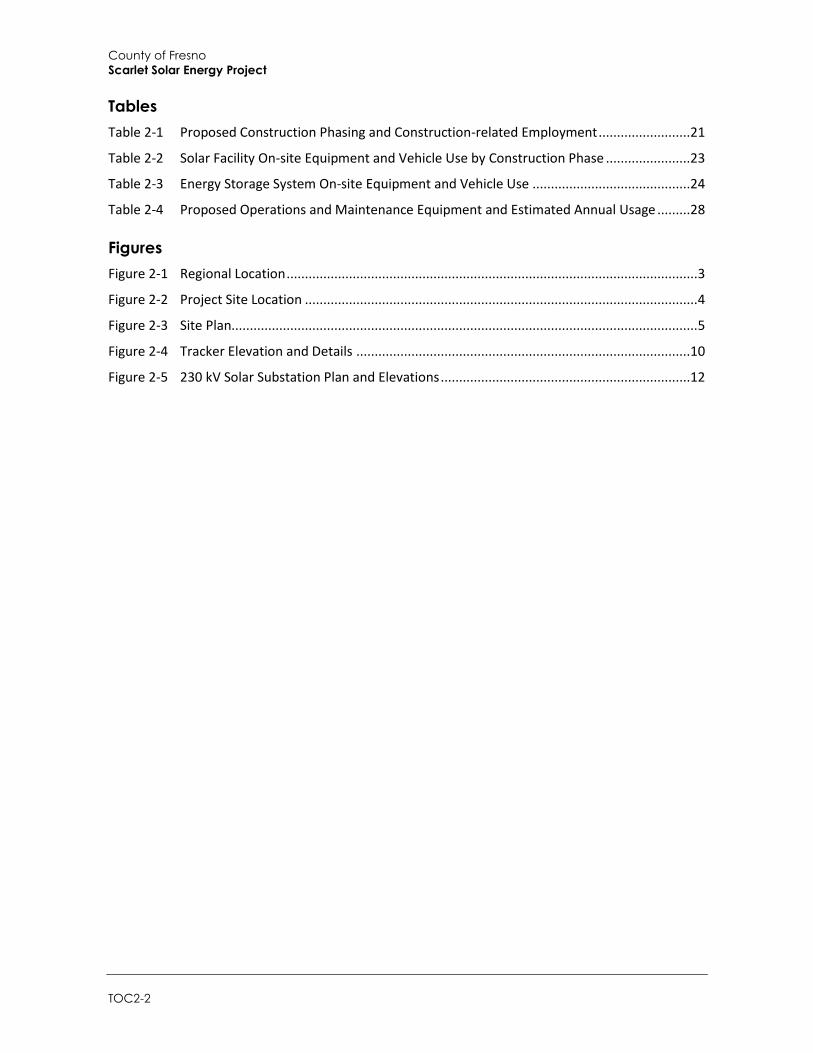
Tables
Table 2-1 Proposed Construction Phasing and Construction-related Employment .........................21
Table 2-2 Solar Facility On-site Equipment and Vehicle Use by Construction Phase .......................23
Table 2-3 Energy Storage System On-site Equipment and Vehicle Use ...........................................24
Table 2-4 Proposed Operations and Maintenance Equipment and Estimated Annual Usage .........28
Figure 2-2 Project Site Location ........................................................................................................... 4
Figure 2-3 Site Plan............................................................................................................................... 5
Figure 2-4 Tracker Elevation and Details ...........................................................................................10
Figure 2-5 230 kV Solar Substation Plan and Elevations ....................................................................12
Project Description
Draft Environmental Impact Report 2-1
2 Project Description
This section describes the proposed project, including the project applicant, the project site and surrounding land uses, major project characteristics, project objectives, and discretionary actions needed for approval.
2.1 Project Overview
The Scarlet Solar Energy Project is proposed by RE Scarlet LLC (Applicant), a wholly owned subsidiary of Recurrent Energy (RE) LLC. The Applicant has applied to the Fresno County Department of Public Works and Planning (the County) for an Unclassified Conditional Use Permit (UCUP) to construct, operate, maintain, and decommission a solar photovoltaic (PV) electricity generating and energy storage facility and associated infrastructure to be known as the Scarlet Solar Energy Project (Project). The Project would generate a total of up to 400 megawatts of alternating current (MWac) at the point of electrical grid interconnection on approximately 4,089 acres in unincorporated western Fresno County. The Project would provide solar power to utility customers by interconnecting to the regional electricity grid at Pacific Gas and Electric Company’s (PG&E) existing Tranquillity Switching Station located just west of the Project site.
The Project would operate year-round to generate solar electricity during daylight hours, and would store and dispatch power at the energy storage system during both daylight and non-daylight hours. The Project is anticipated to be constructed in continuous phases, with the first phase beginning in mid-2020. The exact timing of the last phase is dependent on opportunities in the solar market, but it is currently anticipated to be online as early as late 2021.
Components of the Project would include:
Groups of solar arrays (arrays include PV modules and steel support structures, electrical inverters, transformers, cabling, and other infrastructure)
Two electrical substations
The Project switchyard, including one high-voltage 230-kV utility switchyard, a 140-foot radio tower for telecommunications, and two 150-foot dead-end structures
Approximately 3.1 miles of 230 kV generator intertie (gen-tie) transmission line (from the substations and the Project 230-kV switchyard) to connect to PG&E’s Tranquillity Switching Station
Approximately 2,000 feet of PG&E 230 kV transmission line to connect the Scarlet Solar Project 230 kV gen-tie line to PG&E’s Tranquillity Switching Station
A 400 MW energy storage system, consisting of battery or flywheel enclosures and electrical cabling
Other necessary infrastructure, including one permanent operation and maintenance (O&M) building, a septic system and leach field, a supervisory control and data acquisition (SCADA)
County of Fresno
Scarlet Solar Energy Project
2-2
system, a meteorological data system, buried conduit for electrical wires, overhead collector lines, on-site access roads, a shared busbar1, and wildlife-friendly security fencing.
2.2 Lead Agency
County of Fresno Department of Public Works and Planning 2220 Tulare Street, 6th Floor Fresno, California 96721 Contact: Christina Monfette (559) 600-4245
2.3 Project Applicant
RE Scarlet LLC 353 Sacramento Street San Francisco, California 94111 Contact: Christy Herron
2.4 Property Owner
Westlands Water District 3130 North Fresno Street Fresno, California 93703-6056
2.5 Project Location
The Project site is located in unincorporated Fresno County, approximately 4.2 miles west-southwest of the community of Tranquillity and approximately 10 miles east of Interstate 5 (I-5). The Project site is located northeast of and adjacent to the Tranquillity Solar Generating Facility, which is currently under construction. The Project site would encompass up to 28 parcels2 generally located south of West South Avenue, north of West Dinuba Avenue, east of State Route 33 (SR 33; South Derrick Avenue), and west of South San Mateo Avenue. Figure 2-1 and Figure 2-2 show the location of the Project site on a regional and local scale, respectively. The Project site would be arranged as shown in the preliminary site plan (Figure 2-3). As shown on Figure 2-2 and Figure 2-3, approximately 76 acres of federally owned land are surrounded by the Project site but are not proposed as part of the Project.3
1 A busbar is a system of electrical conductors in a generating or receiving station on which power is concentrated for distribution to several electrical circuits. 2 The project would be constructed on any or all of assessor parcels 028-07-134, 028-07-139, 028-07-140, 028-07-141, 028-07-143, 028-07-144, 028-07-145, 028-07-147, 028-07-148, 028-07-149, 028-08-166, 028-11-101, 028-11-102, 028-11-104, 028-11-106, 028-11-107, 028-11-109, 028-11-110, 028-11-112, 028-11-113, 028-11-114, 028-11-115, 028-11-116, 028-11-117, 028-11-119, 028-11-120, 028-12-061, 028-12-062. 3 The project site excludes assessor parcels 028-12-033, 028-12-035, 028-12-037, and 028-12-039.
Project Description
Draft Environmental Impact Report 2-3
Figure 2-1 Regional Location
County of Fresno
Scarlet Solar Energy Project
2-4
Figure 2-2 Project Site Location
Project Description
Draft Environmental Impact Report 2-5
Figure 2-3 Site Plan
County of Fresno
Scarlet Solar Energy Project
2-6
2.6 Existing Site Characteristics
2.6.1 Existing Land Use
The Project site is designated as Exclusive Agriculture in the Fresno County General Plan (2000) and is zoned AE20 (Exclusive Agriculture, 20-acre minimum required). The property is currently owned by Westlands Water District (WWD).4
The existing land use of the Project site is primarily dry-farmed agriculture that has been intermittently irrigated. For the past 10 years, the Project site intermittently has been in low-yield agricultural production (tilled, seeded, and harvested for winter wheat); intermittently irrigated (drip or sprinkler) and harvested for alfalfa seed or other crops; or disked twice a year and left fallow. The site is subject to high levels of selenium and a water table that does not provide for sufficient drainage for most commercially irrigated crops. Furthermore, the entire Project site is part of Westlands Water District settlements that require a non-irrigation covenant upon transfer of ownership. For the portion of the Project site that is cultivated without the benefit of irrigation, the productivity of these crops depends entirely on rainfall. When the unirrigated crops fail to mature to harvest, the land is grazed as rangeland grasses. There are no Williamson Act contracts binding any of the parcels.5
Two existing PG&E transmission lines are located on the north side of Dinuba Avenue, along the southern portion of the Project site (Figure 2-3). There also are existing PG&E utility lines within the site. These would remain in place with an easement granted to PG&E for access.
Approximately 76 acres of federally owned land are surrounded by the Project site but are not proposed as part of the Project. This land would not be contained within the Project security fence, and the existing legal access would be retained. It is anticipated that the existing use of this land for occasional dry farming followed by periods of fallow use would continue if the Project is approved. This parcel is not subject to a Williamson Act contract.
Roadways surrounding the Solar Facility site comprise of West Dinuba Avenue and State Route 33 (West Derrick Avenue), both of which are paved, as well as South San Mateo Avenue and West South Avenue, which are dirt. These roads range between 15-feet and 50-feet in width and provide a buffer between the Project site and the parcels to the north, west, south, and east.
2.6.2 Surrounding Land Uses
Existing land uses surrounding the Project site consist of agriculture, solar development, and two rural residences. Non-irrigated agricultural land surrounds the Project site to the north, east, and west. These lands are owned mostly by Westlands Water District, which keeps them in various states of low-value agricultural production. The Tranquillity Solar Generating Facility, which is under development, and two rural residences also borders the Project site to the south. The Adams East Solar Facility is located approximately 0.4 mile northwest of the project site.
4 The Westlands Water District acquired this property as part of the following settlements: (1) the September 3, 2002 settlement agreement reached among the United States, Westlands Water District, and others in the Sumner Peck Ranch et al. v. Bureau of Reclamation et al. lawsuit; (2) the Britz settlement (a separate action executed on September 3, 2002); and (3) the 2002 settlement agreement reached in the Sagouspe et al. v. Westlands Water District et al. lawsuit. 5 The Williamson Act (also known as the California Land Conservation Act of 1965) enables local governments to enter into contracts with private landowners for the purpose of restricting specific parcels of land to agricultural or related open space use. The contracted land is then restricted to agricultural and compatible uses through a rolling-term, 10 year contract between the private land owner and the local government.
Project Description
Draft Environmental Impact Report 2-7
2.7 Project Background
The California Renewable Portfolio Standard (RPS) legislation enacted in 2002 (Senate Bill 1078) and accelerated in 2006 required retail sellers of electricity to obtain 20 percent of their supply of electricity from renewable energy sources, such as solar, by 2010. Subsequent recommendations advocated a goal of 33 percent by 2020, which Governor Arnold Schwarzenegger set as a statewide goal when he signed Executive Order S-14-08. The following year, Executive Order S-21-09 directed the California Air Resources Board, under its Assembly Bill 32 authority, to enact regulations to achieve the goal of 33 percent renewables by 2020 (California Energy Commission 2014). The 33 percent goal was enacted into law by Governor Brown on April 13, 2011 with his signing of Senate Bill 2X. The California Public Utilities Commission states that the state’s investor-owned utilities (including PG&E, Southern California Edison, and San Diego Gas & Electric) collectively served 22.7 percent of their 2013 retail electricity sales with renewable energy sources, and that they have all exceeded the contractual requirements for reaching 33 percent by 2020 (California Public Utility Commission [CPUC] 2016). To set a higher goal, on October 7, 2015, Governor Brown signed Senate Bill 350, known as the Clean Energy and Pollution Reduction Act of 2015, which increased California’s RPS to 50 percent by 2030.
Power generated by the Project would be delivered directly via the California Independent System Operator (CAISO) electrical transmission system pursuant to the terms of one or several power purchase agreements.
2.8 Project Objectives
The Applicant has identified the following objectives for the Project:
Establish a solar photovoltaic power-generating facility of a sufficient size and configuration to produce up to 400 MWac of electricity at the Point of Interconnection in a cost competitive manner.
Develop sites in close proximity to transmission infrastructure in order to minimize environmental impacts.
Interconnect directly to the CAISO high-voltage electrical transmission system (grid).
Use proven and established PV technology that is efficient, low maintenance, and recyclable.
Assist California utilities in meeting their obligations under California’s Renewable Portfolio Standard (RPS) Program, including 33 percent of retail sales from renewable sources by the end of 2019 and 50 percent by the end of 2030.
Assist California utilities in meeting their obligations under the CPUC’s Energy Storage Framework and Design Program, including procurement targets of 1,325 MWs by 2020, by providing up to 400 MW of storage capacity.
Facilitate grid integration of intermittent and variable PV generation and minimize line losses associated with off-site storage by collocating battery storage at the PV facility site.
Assist California in meeting the greenhouse gas (GHG) emissions reduction goals by 2020 and 2030 as required by the California Global Warming Solutions Act (Assembly Bill 32 and Senate Bill 32).
County of Fresno
Scarlet Solar Energy Project
2-8
2.9 Project Facilities
The Project would comprise a new Solar Facility that includes solar PV modules (or modules), support structures, electrical inverters, and intermediate voltage transformers. The Solar Facility would include two substations which would receive consolidated intermediate voltage cables from the collector system and step the voltage up to 230 kV via high voltage transformers located in the individual PV substation or shared facilities (Figure 2-3). Each substation area would include an electrical control building. Other necessary infrastructure would include one permanent operation and maintenance building, a supervisory control and data acquisition (SCADA) system, up to 400 MW of on-site battery storage, meteorological data system, telecommunications infrastructure, access roads, and security fencing. The proposed substations would tie into PG&E‘s high-voltage 230 kV Tranquillity Switching Station, which would connect to PG&E’s two existing 230 kV transmission lines located directly adjacent to the Switching Station. The components of the proposed facility are discussed below.
2.9.1 Photovoltaic Modules and Support Structures
The Solar Facility would include an estimated 2 million to 6 million solar modules, although the precise module count would depend on the technology ultimately selected. The ultimate decision for the module types and racking systems described herein would depend on market conditions and environmental factors, including the recycling potential of the modules at the end of their useful lives.
Types of modules that may be installed include thin-film modules (including cadmium telluride [CdTe or “cad tel”] and copper indium gallium diselenide [CIGS] technologies), crystalline silicon modules, or any other commercially available PV technology. Solar thermal technology is not being considered. Module mounting systems that may be installed include either fixed-tilt or tracking technology, depending on the PV modules ultimately selected. Multiple types of modules and racking systems may be installed across the site.
The PV modules would be manufactured at an offsite location and transported to the solar facility site. Modules would be arranged in strings with a maximum height of 12 feet. Module faces would be minimally reflective, dark in color, and highly absorptive of light.
Modules would be arranged on the site in solar arrays. For single-axis tracking systems, the length of each row of modules would be approximately 350 feet along the north/south axis. For fixed-tilt systems, a row consists of multiple tables (4 modules high by 10 modules wide, depending on design), each table approximately 65 feet along the east/west axis, with 1 foot spacing between each table. Spacing between each row would be a minimum of 4 feet. The solar module array would generate electricity directly from sunlight, collect it to a single point at one of the Project substations, and interconnect it to PG&E’s transmission and distribution system.
Structures supporting the PV modules would consist of steel piles (e.g., cylindrical pipes, H-beams, or similar), which would be driven into the soil using pneumatic techniques, such as a hydraulic rock hammer attachment on the boom of a rubber-tired backhoe excavator. The piles typically would be spaced 10 feet apart. For a single-axis tracking system, piles typically would be installed to a reveal height of approximately 4 feet above grade, while for a fixed-tilt system the reveal height would vary based on the racking configuration specified in the final design. For single-axis tracking systems, following pile installation the associated motors, torque tubes, and drivelines (if applicable) would be placed and secured. Some designs allow for PV modules to be secured directly to the torque
Project Description
Draft Environmental Impact Report 2-9
tubes using appropriate module clamps. For some single-axis tracking systems, and for all fixed-tilt systems, a galvanized metal racking system, which secures the PV modules to the installed foundations, would then be field-assembled and attached according to the manufacturer’s guidelines.
Fixed-tilt arrays would be oriented along an east-west axis with modules facing generally south. Tracking arrays would be oriented along a north-south axis with modules tracking east to west to follow the movement of the sun. The total height of the module system measured from ground surface would be up to 12 feet. Figure 2-4 shows an elevation drawing of the solar modules and tracking system. For fixed-tilt systems, the modules would be fixed at an approximate 20- to 60-degree angle or as otherwise determined necessary during final Project design.
Where excavations are required, the majority of proposed construction activities would be limited to less than 6 feet in depth, however, some excavations, such as those undertaken for the installation of collector poles and dead-end structures (see 2.9.2 for details), may reach depths of 20 feet or more.
Per Fresno County policy, the solar modules would be setback a minimum of 50 feet from the property line and neighboring agricultural operations along SR 33 (South Derrick Avenue), South Monterey and South Stanislaus Avenue to the west; West South Avenue and West Manning Avenue to the north; South San Mateo Avenue and South Oil City Avenue to the east; and West Dinuba Avenue to the south.
2.9.2 Inverters and Transformers
The Solar Facility would be designed and laid out in approximately 2 MW increments which would include an inverter equipment area measuring approximately 40 feet by 25 feet. However, the final increment sizes ultimately would depend on available technology and market conditions. Each 2 MW increment would include an inverter-transformer station constructed on a concrete pad or steel skid, and centrally located within the PV arrays. Each inverter-transformer station would contain up to four inverters, a transformer, a battery enclosure, and a switchboard approximately 8 to 11 feet high. If required based on site meteorological conditions, an inverter shade structure would be installed at each pad. The shade structure would consist of wood or metal supports and a durable outdoor material shade structure (metal, vinyl, or similar). The shade structure would extend up to 10 feet above the top of the inverter pad.
Modules would be electrically connected into module strings using wiring secured to the module racking system. Underground cables, either rated for direct bury or installed in PVC conduit, would be installed to convey the direct current (DC) electricity from the modules via combiner boxes located throughout the PV arrays, to inverters to convert the DC to alternating current (AC). The output voltage of the inverters would be stepped up to the collection system voltage via transformers located in close proximity to the inverters shown in the diagram in Figure 2-4. The 34.5 kV level collection cables would either be buried underground or installed overhead on wood poles up to 70 feet tall. Some of the wood poles could be located at the outside edge of the property line, but a majority of these poles are expected to be located interior to the site. Between 300 and 500 wood poles located at 250-foot intervals could be installed across the entire Solar Facility site. The typical height of the poles would be approximately 50 to 60 feet, with diameters varying from 12 to 14 inches.
County of Fresno
Scarlet Solar Energy Project
2-10
Figure 2-4 Tracker Elevation and Details
Source: Recurrent Energy 2017
Project Description
Draft Environmental Impact Report 2-11
2.9.3 Project Substations and Gen-Tie Transmission Lines
The two substations would transform voltage from 34.5 kV to 230 kV. The area of each substation and associated equipment would be approximately 30,000 square feet (150 feet by 200 feet). Figure 2-3 shows the substation locations. Each substation would collect consolidated intermediate voltage cables from the PV collector system.
Structural components in each substation area would include:
Power transformers (approximately 25 feet by 40 feet, and 25 feet high)
Footings for power transformers
Pre-fabricated control buildings (each approximately 23 feet by 15 feet, and 12 feet high) to enclose the protection and control equipment, including relays and low voltage switchgear
Footings (up to 12 feet deep) for the control enclosure structure
Metering stand and capacitor bank(s)
Circuit breakers and air disconnect switches
A telecommunications tower up to 65 feet in height
One microwave tower adjacent to the control building comprising a monopole structure up to 50 feet in height mounted with an antenna up to 5 feet in diameter
Dead-end structure(s) to connect Project substation(s) to the PG&E Tranquility Switching Station
Two equipment storage containers measuring 40 feet by 8 feet by 9 feet each also would be located at each substation area
The substation areas would be graded and compacted to an approximately level grade. Concrete pads would be constructed on site as foundations for substation equipment, and the remaining area would be graveled to a maximum depth of approximately 6 inches. Because each of the substation transformers would contain mineral oil (see Section 2.10.2), the substations would be designed to accommodate an accidental spill of transformer fluid by the use of containment‐style mounting. Each substation would be surrounded by an up-to 8-foot high chain link fence topped with one foot of barbed wire. Each of the dead-end structures would require foundations excavated to a depth of 20 feet or more. Diagrams showing the substation plan, elevation, dead end structure elevation, and control enclosure elevations are provided in Figure 2-5.
Electrical transformers, switchgear, and related substation facilities would be designed and constructed to transform medium-voltage power from the Project’s delivery system to the 230-kV gen-tie transmission lines (carried on either a single set of double-circuit structures or two sets of single-circuit transmission structures) connecting the Project site to the PG&E Switching Station via a new segment of transmission line (see Section 2.9.4). The gen-tie structures would include tubular steel poles and H-frame structures with foundations excavated to a depth of 20 feet or more. The overhead gen‐tie line would be up to approximately 3.1 miles long and consist of up to 30 structures. The structures would be up to 150 feet tall, although most would likely be up to 110 feet.
Other electrical upgrades within the CAISO system could be triggered in part by the proposed Project in combination with other projects in the CAISO queue. In particular, it is anticipated that lower voltage power lines could require reconductoring. Reconductoring is the process of replacing a lower-capacity conductor on existing power poles. Reconductoring associated with the project would not require new ground disturbance and would typically be completed during daylight hours over the course of 6 weeks or less by a crew of line working personnel.
County of Fresno
Scarlet Solar Energy Project
2-12
Figure 2-5 230 kV Solar Substation Plan and Elevations
Source: Recurrent Energy 2017
Project Description
Draft Environmental Impact Report 2-13
2.9.4 PG&E Transmission Line
To interconnect the Scarlet Solar Project 230 kV gen-tie line (see Section 2.9.3) to the PG&E Switching Station, PG&E would construct a new 230 kV transmission line that would extend from the Tranquillity Switching Station to a point located just east of the Tranquillity Solar Project boundary. The PG&E transmission line would include up to 2,000 feet of 230-kV conductor strung on up to 15 new or existing poles that would be up to 150 feet high.
2.9.5 Other Infrastructure
2.9.5.1 Operation and Maintenance Building
An operation and maintenance (O&M) building to accommodate 8 permanent operation and maintenance staff would be required for the Project. The Applicant may use an existing home/trailer that is located southeast of the intersection of West Dinuba Avenue and SR 33, and is already in use by the Applicant for the Tranquillity Solar Project. If a new O&M building is constructed, it would be approximately 2,000 square feet in size (approximately 40 feet by 50 feet by 15 feet at its tallest point) and located within the Project site near the main substation. The O&M building would include permanent plumbing and restroom facilities for use by the staff, including an underground septic system and leach field. Personnel temporarily on-site to perform periodic module washing (up to 4 times per year) would be provided with portable restrooms on the Project site, as well as bottled water for drinking and hand washing. The O&M building would be constructed on concrete foundations.
2.9.5.2 Septic System and Leach Field
A septic system and leach field would be installed adjacent to the O&M building to support the restroom facilities and sewage needs of the 8 permanent staff working 8 hours per day at the O&M building during operation.
Wastewater from the building would be discharged into the septic tank for minimum detention period of 24 hours where most of the solids would be removed (see Section 2.10.1). The 1,000-gallon septic tank would then discharge effluent to approximately 420 feet of disposal trench consisting of seven 60-foot long trenches. The trenches would be approximately 3 feet wide, 4.5 feet deep, with 3 feet of drain rock below the drain line (equivalent to 7 square feet of absorption area per linear foot trench). The leach field would also have a 100 percent expansion area in the event that additional percolation area is necessary.
2.9.5.3 Supervisory Control and Data Acquisition System
The facility would be designed with a comprehensive SCADA system to allow remote monitoring of facility operation and/or remote control of critical components. The fiber optic or other cabling required for the monitoring system typically would be installed in buried conduit, leading to a SCADA system cabinet centrally located within the Project site or a series of appropriately located SCADA system cabinets constructed within the O&M buildings. The dimensions of each cabinet would be approximately 20 feet by 8 feet by 9 feet high. External telecommunications connections to the SCADA system cabinets could be provided through wireless or hard wired connections to locally available commercial service providers.
County of Fresno
Scarlet Solar Energy Project
2-14
2.9.5.4 Storage System
Storage systems can assist grid operators in more effectively integrating intermittent renewable resources into the statewide grid and can assist utilities in their efforts to meet energy storage goals mandated by the CPUC. The Project could include, at the Applicant’s option, a battery or flywheel storage system capable of storing up to 400 MW of electricity. If provided, the storage system would consist of battery or flywheel banks housed in electrical enclosures and buried electrical conduit. The battery system would either be concentrated near the Project substations or dispersed throughout the Solar Facility site. Electrical enclosures measuring 40 feet by 8 feet by 8.5 feet high would be installed on concrete foundations designed for secondary containment. The Project could use any commercially available battery technology, including but not limited to lithium iron, lead acid, sodium sulfur and sodium or nickel hydride. Battery systems are operationally silent, and flywheel systems have a noise rating of 45 dBA.
2.9.5.5 Meteorological Data Collection System
The Solar Facility would include a meteorological (met) data collection system. Each met station would have multiple weather sensors: a pyranometer for measuring solar irradiance, a thermometer to measure air temperature, a barometric pressure sensor, and wind sensors to measure speed and direction. The 4-foot horizontal cross-arm of each met system would include the pyranometer mounted on the left hand side and the two wind sensors installed on a vertical mast to the right. The temperature sensor would be mounted inside the solar shield behind the main mast. Each sensor would be connected by cable to a data logger inside the enclosure.
2.9.5.6 Telecommunications Facilities
The Solar Facility’s SCADA system would interconnect to this fiber optic network at PG&E’s Tranquillity Switching Station, and no additional disturbance associated with telecommunications is anticipated.
2.9.5.7 Access Roads
The main access to the Project site would be provided from West Manning Avenue to South Monterey Avenue with multiple points of ingress/egress for emergency access. Public access and vehicle use of West Manning Avenue (paved) and unpaved roadways6 in the Project area would not be affected by the Project. In addition, there is a California Department of Transportation (Caltrans) future right-of-way adjacent to SR 33 (South Derrick Avenue), which would be avoided by the Project. The Project modules and electrical infrastructure would be set back from the existing SR 33 highway by a minimum of 50 feet plus additional clearance for any deed restrictions and the future right-of-way.
The Solar Facility on-site roadway system would include a perimeter road, access roads, and internal roads. The perimeter road and main access roads would be approximately 20 to 30 feet wide and constructed to be consistent with facility maintenance requirements and Fresno County Fire Department standards. These roads would be surfaced with gravel, compacted dirt, or another commercially available surface and would provide a fire buffer, accommodate Project O&M activities such as cleaning of solar modules, and facilitate on-site circulation for emergency vehicles.
6 It should be noted that these unpaved roads are private roads that are not maintained by the County.
Project Description
Draft Environmental Impact Report 2-15
Internal roads would have permeable surfaces and be approximately 12 to 20 feet in width or as otherwise required by Fresno County Fire Department standards. They would be treated to create a durable, dustless surface for use during construction and operation. This would likely involve surfacing with gravel, compacted native soil, or a dust palliative and would not involve lime treatment. Temporary driveway aprons to points of ingress/egress during construction, such as along West Manning Avenue to South Monterey Avenue, may be up to 80 feet wide to accommodate construction traffic; however, permanent driveway aprons would be built according to Fresno County Improvement Standards. During decommissioning of the facility, it is anticipated that the same access roads would be used for removal of the facility components.
2.9.6 Solar Facility Site Safety and Security
2.9.6.1 Controlled Access
Multiple points of ingress/egress would be accessed via locked gates located at multiple points along the perimeter fence from West Manning Avenue.
2.9.6.2 Fencing
The boundary of the Project site would be secured by up to 8-foot-high chain-link perimeter fences, topped with three-strand barbed wire. The fence design would be either traditional or “wildlife friendly,” i.e., the bottom of the fence would be 5 inches above ground, on average, as measured from the top of the ground to the lowest point of the bottom of the fence. This design would allow wildlife to move freely into and out of the Project site. Public access rights on roadways through the Project area would not be affected by the type of project fencing. Existing public vehicle use of West Manning Avenue and other private unpaved roadways would continue through the Solar Facility.
2.9.6.3 Lighting
Motion sensitive, directional security lights would be installed to provide adequate illumination around the substation areas, each inverter cluster, at gates, and along perimeter fencing. All lighting would be shielded and directed downward to minimize the potential for glare or spillover onto adjacent properties. All lighting also would conform to applicable Fresno County rules and regulations for outdoor lighting.
2.9.6.4 Other Security Measures
Off-site security personnel could be dispatched during nighttime hours or could be on-site, depending on security risks and operating needs. Infrared security cameras, motion detectors, and/or other similar technology would be installed to allow for monitoring of the site through review of live footage 24 hours per day, 7 days per week. Such cameras or other equipment would be placed along the perimeter of the facility and/or at the inverters.
2.9.6.5 Signage
During all phases of the Project, signage for safety and identification would be posted around the perimeter of the Project site. No large billboard or signage for advertisement is proposed. All signage would conform to Fresno County signage requirements.
County of Fresno
Scarlet Solar Energy Project
2-16
2.9.7 Site Buffers and Respect for Nearby Agricultural Operations
The Project proposes to maintain a buffer between the site and neighboring agricultural operations:
Per Fresno County Public Works and Planning guidelines, the Scarlet Solar Project will achieve a minimum 50-foot buffer to adjacent properties by excluding structural improvements and equipment (excluding fencing) from within 50 feet of the outside boundary of the Scarlet Solar Project.
An up to 8-foot chain-link galvanized metal fence topped with standard three-strand barbed wire will surround the Project.
Internal perimeter roads a minimum of 20 feet wide will be installed along the outside edges of the Site between the fence and the solar modules.
The modules produce minimal glare. The system operates quietly and does not use any fluids or emit any odors. Given the modules’ sensitivity to dust and dust’s resulting impact on power production, the site will be managed to minimize dust and prevent weed growth. As described in Section 2.14, weeds and pests will be continuously managed such that the Project does not harbor or serve as a source of pests for neighboring farms. Rodent populations represent a risk to system performance given the potential for chewing wires, as such the Project site will be actively monitored and if rodents are found, remedial actions will be taken.
2.10 Water Requirements and Waste Generation
2.10.1 Water and Wastewater
2.10.1.1 Water
During the construction phase, if grading and grubbing is required at the project site, it is anticipated that a total of up to 360 acre-feet7 of water would be used for dust suppression (including truck wheel washing) and other purposes (Recurrent Energy 2018). If grading and grubbing is not required at the Project site, water needs would be less.
During the operation and maintenance phase (which would last up to 40 years), water would be required for module washing and maintenance and for the O&M building restroom facilities. The Solar Facility would require the use of approximately 20 acre-feet annually for module washing and other uses, equivalent to 0.05 acre-feet (or 16,250 gallons) per MW annually. Of this, approximately 1.5 acre-feet of non-potable water would be used by employees on-site for washing or rinsing equipment, hand washing, and other non-toilet uses. Approximately 1.47 acre-feet would be used for washing the modules up to four times a year (up to 3.7 acre-feet of water per washing period). The remaining estimated water would be used to support on-site sheep (if grazing is used for weed control) and other miscellaneous needs (Recurrent Energy 2018).
The Project site does not receive any surface water from Westlands Water District (WWD). The entire Project site is part of two Westlands Water District settlements that require a non-irrigation covenant to be recorded upon transfer of ownership. During construction, water would be obtained from an existing well on the neighboring Tranquillity Solar Generating Station project site or another
7 One acre-foot of water equals 325,851 gallons – approximately the amount needed to cover an acre (roughly a football field) of ground one foot deep.
Project Description
Draft Environmental Impact Report 2-17
location, and/or would be trucked to the site. Water used for module washing during operation would be obtained either from this same well or trucked in from an off-site local water purveyor.
During construction, restroom facilities would be provided by portable units to be serviced by licensed providers. Potable water, for drinking and hand washing, would be brought to the site by construction employees or by a bottled water service provider.
During operation, potable water would be supplied to the O&M building by a licensed provider.
2.10.1.2 Wastewater
A septic system and leach field would be installed adjacent to the O&M building to support the restroom facilities and sewage needs of the 8 permanent staff (8 hours per day) at the O&M building during operation. Personnel on-site to perform module washing (up to 4 times per year) would be provided with portable restrooms serviced by a licensed provider. Anticipated peak flow is 600 gallons into the leach field per day during Project operation (or 0.67 acre-feet per year) (Recurrent Energy 2018). No surface discharges are proposed, other than natural stormwater runoff. A Waste Discharge Permit would not be required from the Regional Water Quality Control Board (RWQCB) because the Project would not exceed 2,500 gallons per day of sewage. The septic system would be required to be permitted by the Fresno County Department of Public Works and Planning. The septic system and leach field testing procedures and design would meet all applicable specifications and regulations.
2.10.2 Solid Waste
Construction and decommissioning of the Project would involve the use of hazardous materials, such as fuels and greases to fuel and service construction equipment. Such substances may be stored in temporary aboveground storage tanks or sheds located on the Project site. The fuels stored on-site would be in a locked container within a fenced and secure temporary staging area (see Section 2.11.1). If the quantities stored are estimated to be in excess of 1,3208 gallons, storage would be undertaken in compliance with the Spill Prevention, Control, and Countermeasure (SPCC) Rule and a Hazardous Materials Business Plan, which would be developed prior to construction for submission to the Fresno County Division of Environmental Health. Trucks and construction vehicles would be serviced from off-site facilities. The use, storage, transport, and disposal of hazardous materials used in construction of the facility would be carried out in accordance with federal, state, and county regulations. No extremely hazardous substances (i.e., those governed pursuant to Title 40, Part 335 of the Code of Federal Regulations) are anticipated to be produced, used, stored, transported, or disposed of as a result of project construction. Material Safety Data Sheets for all applicable materials present on-site would be made readily available to on-site personnel.
Construction materials would be sorted on-site throughout construction and transported to appropriate waste management facilities. Recyclable materials would be separated from non-recyclable items and stored until they could be transported to a designated recycling facility. It is anticipated that at least 20 percent of construction waste would be recyclable, and 50 percent of those materials would be recycled (Recurrent Energy 2018). Wooden construction waste (such as wood from wood pallets) would be sold, recycled, or chipped and spread on the Project site for
8 Effective January 1, 2008 the Certified Unified Program Agencies (CUPAs) are vested with the responsibility and authority to implement the Aboveground Petroleum Storage Act (APSA). Owners or operators of aboveground petroleum storage tanks are required to file a storage statement and implement spill prevention measures according to the Aboveground Petroleum Storage Act of 1990. Facilities with a single tank or cumulative aboveground storage capacities of 1,320 gallons or greater of petroleum are covered by this law.
County of Fresno
Scarlet Solar Energy Project
2-18
weed control as appropriate. Other compostable materials, such as vegetation, might also be composted off-site. Non-hazardous construction materials that cannot be reused or recycled would likely be disposed of at municipal county landfills. Hazardous waste and electrical waste would not be placed in a landfill, but rather would be transported to a hazardous waste handling facility (e.g., electronic-waste recycling). All contractors and workers would be educated about waste sorting, appropriate recycling storage areas, and how to reduce landfill waste.
Operation and maintenance activities would produce negligible volumes of solid and liquid wastes and are not expected to require hazardous materials or to generate hazardous waste. The transformers proposed to be located at the Project substations would use biodegradable seed oil, which is not a hazardous material. Oil disposal would occur in accordance with applicable regulations. PV modules and the inverters would not produce any waste during operation.
2.11 Construction
2.11.1 Solar Facility Phase 1: Site Preparation
2.11.1.1 Staging and Other Temporary Work Areas
A staging/refueling area would be located at or near the primary access point to the project. Assuming continuous construction, one main staging area would be located near West Manning Avenue at the western end of the site. Preparation of laydown areas would include grubbing, clearing, grading, and compaction. The staging and laydown areas would be used for material and equipment storage, reporting location for workers, parking area for vehicles and equipment, and the ultimate location of the O&M building. Laydown areas would encompass up to 10 acres and would be secured with an 8-foot fence. Temporary power would be provided via mobile generators or local distribution lines.
2.11.1.2 Access Roads
The Project’s on-site roadway system would include a perimeter road, access roads, and internal roads, which are described in Section 2.9.4. Perimeter and site access roads would have 95 percent relative compacted subgrade, and four inches of gravel or equivalent. Internal site roads would have permeable surfaces (4-inch gravel) and be approximately 15 to 20 feet in width. Roads would be treated to create a durable, dust-minimizing surface for use during construction and operation. This would likely involve surfacing with gravel, compacted native soil, or a dust palliative and would not involve lime treatment. Temporary driveway aprons to points of ingress/egress during construction may be up to 80 feet wide to accommodate construction traffic; however, permanent driveway aprons would be built according to Fresno County Improvement Standards. Road construction would proceed as follows: the ground would be grubbed (cleared of vegetation), scarified (loosened up), moisture conditioned, compacted, and graded with a crown in the center.
2.11.1.3 Security Fencing
As described in Section 2.9.6, Project fencing would include perimeter fencing. Fencing would be chain-link galvanized metal, up to 8 feet in height. Perimeter fencing could be topped with standard three-strand barbed wire. Fence posts would be spaced approximately 10 feet apart, drilled and grouted or driven pneumatically into the soil profile up to an estimated 5 feet deep.
Project Description
Draft Environmental Impact Report 2-19
2.11.1.4 Construction-related Grading and Vegetation
Management
As necessary for equipment access, the site would be grubbed and scarified. As the site is nearly flat and has been historically graded/tilled, Project-related grading would be minimal and occur only as necessary to level dips and hills. The site cut and fill would be approximately balanced, or minimal import/export would be necessary. During site preparation, an average of 35 acres in various portions of the site would be disturbed daily at any given time. During Phase 2 (Section 2.11.2), an average of 25 acres would undergo installation at any one time, with an estimated maximum active disturbance area of up to 90 acres when Phase 1 and 2 overlap.
2.11.1.5 Erosion and Sediment Control and Pollution Prevention
As the construction of the Project would result in disturbance of an area greater than 1 acre, the Applicant would be required to enroll under the State Construction General Permit, for the National Pollution Discharge Elimination System program. To enroll under this permit, the applicant would prepare a single or multiple Stormwater Pollution Prevention Plans (SWPPP), which would be based on the final engineering design.
The SWPPP would be prepared by a qualified engineer or erosion control specialist, and would be implemented before construction. The SWPPP would be designed to reduce potential impacts related to erosion and surface water quality during construction activities and throughout the life of the Project. It would include Project information and best management practices (BMPs). The BMPs would include dewatering procedures, stormwater runoff quality control measures, concrete waste management, watering for dust control, and construction of perimeter silt fences, as needed.
The SWPPP would be submitted to the RWQCB and Fresno County prior to issuance of any building or grading permits.
2.11.2 Solar Facility Phase 2: Photovoltaic Module System
2.11.2.1 Standard Installation, Array Assembly, and Racking
The structure supporting the PV module arrays would consist of steel piles (e.g., cylindrical pipes, H-beams, or similar), which would be driven into the soil using pneumatic techniques, similar to a hydraulic rock hammer attachment on the boom of a rubber-tired backhoe excavator. The piles typically are spaced 10 feet apart. For a single-axis tracking system, piles typically would be installed to a reveal height of approximately 4 feet above grade, while for a fixed-tilt system the reveal height would vary based on the racking configuration specified in the final design. For single-axis tracking systems, following pile installation the associated motors, torque tubes, and drivelines (if applicable) would be placed and secured. Some designs allow for PV modules to be secured directly to the torque tubes using appropriate module clamps. For some single-axis tracking systems and for all fixed-tilt systems, a galvanized metal racking system, which secures the PV modules to the installed foundations, would then be field-assembled and attached according to the manufacturer’s guidelines.
County of Fresno
Scarlet Solar Energy Project
2-20
2.11.3 Solar Facility Phase 3: Inverters, Transformers, Substation
and Electrical Collector System
Underground cables to connect module strings would be installed using ordinary trenching techniques, which typically include a rubber-tired backhoe excavator or trencher. Wire depths would be in accordance with local, State, and Federal requirements, and would likely be buried at a minimum of 18 inches below grade, by excavating a trench approximately 3 to 6 feet wide to accommodate the conduits or direct buried cables. After excavation, cable rated for direct burial or cables installed inside a polyvinyl chloride (PVC) conduit would be installed in the trench, and, the excavated soil would likely be used to fill the trench and lightly compressed. All cabling excavations would be to a maximum depth of 10 feet.
All electrical inverters and the transformer would be placed on concrete foundation structures or steel skids. In lieu of steel skids or pre-cast concrete foundations, foundations for the transformer and inverter locations would be formed with plywood, and reinforced with structural rebar. Commissioning of equipment would include testing, calibration of equipment, and troubleshooting. The substation equipment, inverters, collector system, and PV array systems would be tested prior to commencement of commercial operations. Upon completion of successful testing, the equipment would be energized.
The substation areas would be excavated for the transformer equipment and control building foundation and oil containment area. The site area for the substations would be graded and compacted to an approximately level grade. Foundations for the substation would be formed with plywood and reinforced with structural rebar. Concrete pads would be constructed as foundations for substation equipment, and the remaining area would be graveled. Concrete for foundations would be brought on-site from a batching plant in Fresno County.
In addition to the Solar PV Facility, the 400 MW energy storage system, including battery or flywheel enclosures and electrical cabling, would be installed at the Project site, concurrently with Phase 3 or at a later date. The system would be largely assembled offsite and transported to the Project site for installation.
2.11.4 Construction Site Restoration and Revegetation
Following the completion of major construction, the Project site would be re-seeded/re-vegetated with low-growing plant species appropriate for maintaining soil quality and controlling weed growth to reduce fire hazards. Vegetation would be selected based on growth habit (lower growing cover would be preferred) and suitability for the area. Site restoration activities would include:
On-site repurposing or removal of all vegetative material from grubbing, clearing, and pruning;
Removal of all trash and construction debris;
Removal of temporary construction fencing marking the perimeter of sensitive areas (washes, set- aside areas, cultural area); and
Removal of all construction equipment and any supplies and materials that were not consumed on-site.
Following the completion of site restoration maintenance activities, the construction staging areas would be restored to their original condition by the planting of appropriate species.
Project Description
Draft Environmental Impact Report 2-21
2.11.5 Construction Schedule and Workforce
Construction equipment would operate between the hours of 7:00 a.m. and 7:00 p.m. Monday through Friday for up to a maximum of 8 hours per piece of equipment, daily. Weekend construction work is not expected to be required, but may occur on occasion, depending on schedule considerations. All construction work, including any weekend work, would be required to comply with the Fresno County noise ordinance.
Construction of the Solar Facility would commence as early as mid-2020, and the last phase would be expected to be complete as early as late 2021 depending on opportunities in the solar market. Total duration of continuous construction would be approximately 18 months. The Applicant is committed to establishing a point of sale, purchasing a majority of equipment and materials, and hiring locally in connection with the Project. The anticipated construction processes, schedule, and workforce are described in this section.
Agricultural activities are expected to continue during the project construction phase on portions of the Project site not being actively disturbed by construction activities.
Assuming continuous construction, phasing would be as follows:
Phase 1, Site Preparation, would extend for approximately 16 weeks, or 80 working days.
Phase 2, PV Module System Installation (foundations, tracker racks, and modules), would extend for a duration of approximately 56 weeks, or 282 working days, and would overlap Phase 1 by approximately 14 weeks.
Phase 3, Installation of Inverters, Substations, and Connection, would extend for a duration of 24 weeks, or 121 working days, and overlap Phase 2 by about 16 weeks. The proposed energy storage system may be installed concurrently with Phase 3 or at a later date.
Table 2-1 shows the average and maximum number of workers required for construction of the solar facility and energy storage component, as well as the length of each phase. The total number of construction workers at any given time would range between 132 and 678, with the peak number of workers (678) on-site during February and March of 2018. The exact timing of installation of the energy storage component is unknown, but it may overlap with construction of the final phase of the solar facility. The majority of the labor force is expected to be from Fresno and the surrounding communities with a maximum round-trip commute of up to 80 miles (Recurrent Energy 2018).
Table 2-1 Proposed Construction Phasing and Construction-related Employment
Construction Element Construction Phase
Average Number of Workers
Maximum Number of Workers
Length of Phase (work days)
Solar Facility
Site Preparation 309 412 81
Photovoltaic Module System Installation 576 678 282
Inverters, Substation, & Connection 105 140 121
Energy Storage System
Site Preparation 74 98 22
Foundation, Structures, and DC1 63 84 174
Inverters, Substation and AC 54 71 146
1 DC employees include electricians installing battery racks and modules; not running equipment.
County of Fresno
Scarlet Solar Energy Project
2-22
2.11.6 Construction Access, Equipment, and Traffic
All materials for the Project’s construction would be delivered by truck. The majority of truck traffic would occur on designated truck routes and major streets. Flatbed trailers and trucks would be used to transport construction equipment and construction materials to the site. Project components would be assembled on-site. Traffic resulting from construction activities would be temporary and could occur along area roadways as workers and materials are transported to and from the Project site. Materials deliveries during construction would travel up to 115 miles one-way from source to the Project site. Quantities for construction equipment and traffic represent the conservative assumption of construction of the entire project (400 MWac at the Point of Interconnection) simultaneously; should fewer units be constructed these quantities would be reduced. The exact timing of installation of the energy storage system is unknown, but it is conservatively assumed that it may overlap with construction of the final phase of the solar facility.
2.11.6.1 Solar Facility
The anticipated maximum number of vehicle trips per day for each construction phase of the solar facility is as follows9:
Phase 1: Site Preparation
An average of 232 daily worker round trips with an average travel distance of up to 80 miles to and from the project site from the City of Fresno area (assuming 25% of workers carpool to the Project site).
Approximately 8,564 total trips (4,282 round trips) by water tankers of 10,000 gallons each. Each roundtrip would be less than 10 miles total (5 miles each way).
Phase 2: PV Module System/Installation
An average of 432 daily worker round trips with an average travel distance of up to 80 miles to and from the Project site from the City of Fresno area (assuming 25% of workers carpool to the Project site).
Approximately 4,282 total trips (2,141 round trips) by water tankers of 10,000 gallons each. Each roundtrip would be less than 10 miles total (5 miles each way).
Phase 3: Inverter, Transformer, Substation and Electrical System Installation
An average of 79 average daily worker round trips with an average travel distance of up to 80 miles to the Project site from the City of Fresno area (assuming 25% of workers carpool to the Project site).
Approximately 4,282 total trips (2,141 round trips) by water tankers of 10,000 gallons each. Each roundtrip would be less than 10 miles total (5 miles each way).
Equipment and vehicles to be used for the construction of the Solar PV Facility are identified in Table 2-2.
9 Source: Recurrent Energy, Construction Estimating Division, 2018.
Project Description
Draft Environmental Impact Report 2-23
Table 2-2 Solar Facility On-site Equipment and Vehicle Use by Construction Phase
On-site Equipment1 Estimated Usage
Units Hours/Day Total Days Per Unit
Phase 1: Site Preparation
Pickup 12 4 78
Bulldozers 82 7 80
Water Trucks 49 4 80
Graders 2 7 64
Flatbeds 23 4 72
Skid Steers 2 7 12
Front End Loaders 4 7 32
Roller Compactor 6 7 70
Backhoes 4 7 1
Instrument 12 7 78
Gravel Trucks 127 4 80
Phase 2: Photovoltaic Array Installation
Water Trucks 5 4 280
Flatbeds 62 4 282
Skid Steers 10 7 140
Trenchers 12 4 105
Phase 3: Installation Of Inverters, Substations, and Connection
Skid Steer 2 7 62
Pile Drivers 2 7 62
Trenchers 8 4 95
Backhoes 2 7 121
Cranes 6 4 91
Aerial Lifts 8 4 78
Concrete Trucks 21 4 1
1 Off-site truck trips are discussed in Section 2.11.6.1.
2.11.6.2 Energy Storage System
The anticipated maximum number of vehicle trips per day for each construction phase of the energy storage system is as follows10:
Phase 1: Site Preparation
An average of 56 daily worker round trips with an average travel distance of up to 80 miles to and from the project site from the City of Fresno area (assuming 25% of workers carpool to the Project site).
Approximately 3,167 total trips (1,584 round trips) by water tankers of 10,000 gallons each. Each roundtrip would be less than 10 miles total (5 miles each way).
10 Source: Recurrent Energy, Construction Estimating Division, 2018.
County of Fresno
Scarlet Solar Energy Project
2-24
Phase 2: Foundations, Structures and DC Electrical System Installation
An average of 48 daily worker round trips with an average travel distance of up to 80 miles to and from the Project site from the City of Fresno area (assuming 25% of workers carpool to the Project site).
Approximately 1,584 total trips (792 round trips) by water tankers of 10,000 gallons each. Each roundtrip would be less than 10 miles total (5 miles each way).
Phase 3: Inverter, Substation and AC Electrical System Installation
An average of 41 average daily worker round trips with an average travel distance of up to 80 miles to and from the Project site from the City of Fresno area (assuming 25% of workers carpool to the Project site).
Approximately 1,584 total trips (792 round trips) by water tankers of 10,000 gallons each. Each roundtrip would be less than 10 miles total (5 miles each way).
Table 2-3 shows equipment and vehicles to be used for the construction of the energy storage system.
Table 2-3 Energy Storage System On-site Equipment and Vehicle Use
On-site Equipment Estimated Usage
Units Hours/Day Total Days Per Unit
Phase 1: Site Preparation
Pickup 8 4 22
Bulldozers 16 7 22
Water Trucks 14 4 22
Graders 6 7 21
Flatbeds 3 4 18
Skid Steers 1 7 12
Front End Loaders 5 7 20
Roller Compactor 5 7 20
Instrument 8 7 22
Gravel Trucks 161 4 22
Phase 2: Foundations, Structures and DC Electrical System Installation
Pickup 3 4 102
Water Trucks 3 4 102
Skid Steers 3 7 102
Trenchers 2 4 74
Crane 3 4 170
Phase 3: Inverter, Substation and AC Electrical System Installation
Skid Steer 2 7 64
Pile Drivers 2 7 64
Trenchers 7 4 146
Backhoes 3 7 47
Cranes 3 4 121
Aerial Lifts 2 4 70
Concrete Trucks 3 4 1
Project Description
Draft Environmental Impact Report 2-25
2.11.7 Construction Personnel Training
2.11.7.1 Biological Resources
Prior to construction, a qualified biologist would be retained by the Applicant to conduct environmental awareness training for Project personnel. Such training would communicate information related to the protection of sensitive biological resources that might be present at the Project site, and would include:
A description of species of concern and associated habitats.
The general provisions of applicable environmental regulations and the need to adhere to the provisions of the regulations.
General measures being implemented to conserve the species of concern as they relate to the Project.
The training would include a discussion of the defined access routes to the Project site and Project site boundaries within which Project activities must be accomplished. Construction employees would strictly limit their activities, vehicles, equipment, and construction materials to the Project footprint and designated staging areas and routes of travel. The construction areas would be the minimal area necessary to complete the Project and would be specified in the construction plans. Construction areas would be demarcated on-site, and employees would be instructed to limit activities to these areas.
2.11.7.2 Fire Suppression and Safety Training
The Applicant would coordinate with the California Office of the State Fire Marshall and the Fresno County Fire Department to provide training for personnel to safely interrupt electrical power in the event of emergency incidents requiring fire suppression or rescue activities.
To minimize fire risk, combustible vegetation or agricultural products on and around the Project site boundary would be actively managed by the Project owner or its affiliates. Combustible vegetation would either be limited in height or removed. In addition, fire breaks—in the form of 20-foot-wide roads—would be constructed around the Project boundary.
The Applicant would coordinate with the Fresno County Fire District in the development of a Fire Prevention and Emergency Action Plan for the site to address potential exposure to fire and other hazards in the Project site. The plan would include at least the following provisions:
Fire Prevention Training. The Applicant would provide training for fire personnel in the safe interruption of electrical power for emergency incidents requiring fire suppression or rescue activities.
Emergency Action Training. The Applicant would train all construction and operation and maintenance personnel in:
Evacuation routes from the Project site to safe areas, in the event of fire or other natural hazards.
Coordination with local fire department, sheriff department, and emergency medical services.
Safety measures in accordance with the California Occupational Safety and Health Administration (Cal/OSHA) regulations and guidance for construction, which would be
County of Fresno
Scarlet Solar Energy Project
2-26
reviewed by all Project construction staff prior to starting work. Safety measures would include those that address potential electrical incidents and fire hazards.
Fire Prevention Measures. The Applicant would implement the following measures during Project construction and operation:
All applicable Fresno County improvement standards would be followed, to ensure accessibility and ground clearance of emergency vehicles (e.g., fire engines).
Vegetation would be maintained to reduce potential fire hazards at the Project site.
Smoking would be prohibited at the Project site, except within designated areas.
Work crews would be required to park vehicles away from flammable vegetation such as dry grass and brush. At the end of each workday, heavy equipment would be required to be parked over mineral soil, asphalt, or concrete, where available, to reduce the risk of fire.
Fire-suppression equipment (e.g., fire extinguishers) would be made available on the Project site at all times. All heavy equipment would be required to include mechanisms for fire suppression, including spark arresters or turbo-charging (which eliminates sparks in exhaust) and fire extinguishers.
2.12 Operation and Maintenance
Upon commissioning, the Project would enter the operation phase. The solar modules at the site would operate during daylight 7 days per week, 365 days per year.
Operational activities at the Project site would include:
Solar module washing
Vegetation, weed, and pest management
Security
Responding to automated electronic alerts based on monitored data, including actual versus expected tolerances for system output and other key performance metrics
Communicating with customers, transmission system operators, and other entities involved in facility operations
2.12.1 Operation and Maintenance Workforce
Up to 8 permanent staff could be on the site at any one time for ongoing facility maintenance and repairs. On intermittent occasions, up to 25 workers could be required on-site if repairs or replacement of equipment were needed in addition to module washing. A record of inspections would be kept on-site. The duration of scheduled maintenance activities would vary in accordance with the required task, but could involve up to 40 workers full-time for up to 2 weeks up to four times per year for module washing, and a similar number and duration for workers regularly visiting the site for routine maintenance activities. The maximum number of staff on-site at any time would be 48 (40 temporary staff and 8 permanent staff). The personnel and time required for emergency maintenance would vary in accordance with the necessary response.
The majority of the operational labor force is expected to be from Fresno and the surrounding communities with a maximum anticipated commute of 40 miles one way.
Project Description
Draft Environmental Impact Report 2-27
2.12.2 Automated Facility Control and Monitoring System
The facility would be designed with a comprehensive SCADA system to allow remote monitoring of facility operation and/or remote control of critical components. Infrared security cameras, motion detectors, and/or other similar technology also would be installed to allow for monitoring of the site through review of live footage 24 hours per day, 7 days per week.
Facility operators would have a maintenance program that would include an industry standard SCADA. The operators would be on call to respond to alerts generated by the monitoring equipment at the Project site, and would analyze collected data on an ongoing basis to schedule maintenance. The operators or their representatives would continually monitor facility outputs and performance against forecast production to identify equipment failure or abnormalities. Attributes that would be monitored include:
Energy generated for comparison with expected generation.
Inverter registers for inverter failures, and inverter voltage and current flow for comparison with expected flows.
Combiner output current for combiner and re-combiner failures, and comparison with expected current.
Weather, including horizontal and plane-of-array irradiance, ambient air temperature, wind speed and direction, and back-of-module temperature for: scheduling output to the transmission system operator, comparison with forecasts, and calculation of expected generation and expected currents.
2.12.3 Site Maintenance
The Project site maintenance program would be largely conducted on-site during daytime hours. Equipment repairs could take place in the early morning or evening when the plant would be producing the least amount of energy. Key program elements would include maintenance activities originating from the on-site operation and maintenance facilities and/or a regional operations and maintenance facility located within Fresno County, and on-site maintenance as required to clear weeds for ground-mount systems.
Maintenance typically would include module repairs; module washing; maintenance of transformers, inverters, and other electrical equipment as needed; maintenance of the oil/water separator system; and road and fence repairs. Visual inspections of the transformers and the oil/water separator system would be conducted monthly. Pest and weed management also would be performed in accordance with the Pest and Weed Management Plan. On-site vegetation would be managed to ensure access to all areas of the site and to screen Project elements as needed.
Solar modules would be washed as needed (up to four times each year) using light utility vehicles with tow-behind water trailers, as needed, to maintain optimal electricity production. No chemical cleaners would be used for module washing.
2.12.4 Operation Equipment
Equipment to be used during operation and maintenance of the Project is identified in Table 2-4. Quantities for equipment and traffic represent the conservative assumption of operation of the entire 400 MWac at the Point of Interconnection simultaneously; should fewer units be constructed these quantities would be reduced proportionate to the number of MW actually in operation.
County of Fresno
Scarlet Solar Energy Project
2-28
Table 2-4 Proposed Operations and Maintenance Equipment and Estimated Annual
Usage
On-site Equipment Estimated Usage
Units Hours/Day Days/Week Total Days
All-Terrain Vehicles (ATVs) 4 4 5 5
Kubota Tractors 4 8 5 100
Honda Portable Generators 4 8 5 60
Portable Water Trailers with Pump 10 8 5 80
Units Miles/Round Trip Round Trips/Day Total Days
Ford F150s (Routine O&M) 8 30 1 130
Ford F150s (Water Wash Trucks) 15 40 1 80
2.12.5 Fire Suppression and Safety Training
The fire suppression and safety training that would occur during the operations and maintenance phase of the Project would be similar to that described for the construction phase. It would occur annually and for every new employee.
2.13 Decommissioning and Site Reclamation
2.13.1 Decommissioning of Equipment
The Solar Facility is anticipated to have an operating life of up to 40 years. After this period, the facility would be either repowered or decommissioned. Repowering after the operating life is not anticipated at this time; however, if repowering were to be pursued, it would require the owner to obtain all required permit approvals. Project decommissioning would occur in accordance with the expiration of UCUP and would involve the removal of all above-grade facilities, buried electrical conduit, and all concrete foundations in accordance with a Reclamation Plan. Utility-owned infrastructure would not be removed at the time the Solar Facility is decommissioned. In the event that a structure breaks off 4 feet or more beneath the ground surface, the remaining section would be left in place. If the structure breaks off in the upper 4-foot portion of soil, it would be excavated and removed. Equipment would be repurposed off-site, recycled, or disposed of in a landfill as appropriate. Decommissioning would involve the use of heavy equipment and personnel similar to that used for construction.
For the entire Project site, decommissioning activities are expected to require approximately 3,000 truck trips, a workforce of approximately 100 workers, and would take up to 24 months. Decommissioning may occur simultaneously or individually as the power blocks go offline. Appropriate hazardous materials control and erosion control measures would be used throughout the decommissioning process. It is anticipated that such controls would be substantially similar to those implemented during construction.
2.13.2 Site Reclamation
A Reclamation Plan containing details regarding site reclamation and decommissioning will be submitted by the applicant to Fresno County. All road and other areas compacted during original construction or by equipment used for decommissioning would be tilled in a manner adequate to
Project Description
Draft Environmental Impact Report 2-29
restore the sub-grade material to the proper density and depth consistent with adjacent properties. Low areas would be filled with clean, compatible sub-grade material. After proper sub-grade depth is established, locally-sourced (from the City of Fresno or other location within 40 miles of the Project site) topsoil would be placed to a depth and density consistent with adjacent properties. Locally-sourced compost would be applied to the topsoil, and the entire site would be tilled to further loosen the soil and blend in the compost. An appropriate seed mixture would be broadcast or drilled across the site, and a weed-free mulch would be applied to stabilize the soil and retain moisture for seedling germination and establishment.
2.14 Other Required Permits and Commitments
The Project requires the certification of this EIR and the following approvals from Fresno County.
Unclassified Conditional Use Permit – The Project would require an Unclassified Conditional Use Permit (UCUP) from Fresno County to allow for use of the Project site for a Solar Facility.
Parcel Map – The Project may result in the modification of the existing parcels to create new parcels. This is anticipated to be addressed by Fresno County via a Parcel Map Waiver and would not require an amendment to the County’s General Plan. The Applicant would prepare a parcel map application or lot line adjustment request and submit to the Fresno County Public Works and Planning Department for the creation of these parcel(s).
Building and Grading Permits – Fresno County Building and Grading Permits would be required for the erection, demolition, or conversion of any building or structure. Such permits are ministerial and would be secured prior to the commencement of construction.
Pest and Weed Management Plan – A Pest and Weed Management Plan detailing methods of exotic weed, rodent, nuisance arthropod, and vector control during operation and after decommissioning of the Project has been prepared by the applicant and will be submitted to the County. Among other things, the plan would include vegetation management to discourage the harboring of rodents on-site and prevent impacts on surrounding agricultural operations. The growth of on-site vegetation would be controlled either by periodic mowing, herbicide use, or sheep grazing, as appropriate. All herbicides would be applied by (or under the oversight of) an applicator licensed to apply pesticides in California. Herbicides would be applied in accordance with the label instructions only for their intended use. Applicators would wear all required personal protective equipment.
In addition, the following discretionary approvals from other agencies may be required for the project:
California Regional Water Quality Control Board – A National Pollutant Discharge Elimination System (NPDES) Construction Storm Water Permit would be required for the Project. Construction activities disturbing one acre or more of land are subject to the permitting requirements of the NPDES General Permit for Discharges of Storm Water Runoff Associated with Construction Activity (Construction General Permit) and must apply for Construction General Permit coverage.
California Department of Transportation (Caltrans) – An Oversize/Overweight permit and Traffic Control Plan would be required for the transportation of substation transformers.
State of California, Department of Fish and Wildlife – Authorization to take State-listed species subject to the California Endangered Species Act may be required.
County of Fresno
Scarlet Solar Energy Project
2-30
U.S. Fish and Wildlife Service – A Section 7 Endangered Species Act incidental take statement authorization for take of federally listed species may be required.