7. Supported third party sensor products ........................................ 14
8. Repeater notes ............................................................................. 15 8.1 Power requirements .................................................................... 15 8.2 Product Specification ................................................................... 15 8.3 RSSI indicator (calibrated from serial number 7925 to current) ...... 19 8.4 Radio coverage survey ................................................................. 20 8.5 Preparing the transmitter and repeater for the survey .................. 22 8.6 Carrying out the survey ............................................................... 22
10. Windows issues............................................................................ 25
2
11. FAQs ............................................................................................ 26 11.1 What is the best way to contact a logger remotely using GSM?.. 26 11.2 What are Darca's System Requirements? ..................................... 27 11.3 Why can't I establish a connection to the Squirrel from Darca?.... 27 11.4 I have problem establishing a connection with a logger
attached to a GSM modem. ........................................................ 27 11.5 I have problems with connection reliability when using
Darca with an instrument attached to a GSM modem. ............... 28 11.6 How does the logger store data from pulse transmitters? ........... 28 11.7 The Tx interval on GenII transmitters resets to 5 seconds ............ 28
12. Contacting a logger via GSM ....................................................... 29
15. Thermocouple isolation and interference issues........................... 41
16. Configuring the logger using the buttons ................................... 42
17. Setting up transmitters from the RX250AL ................................... 43
3
17.1 Initial Setup .................................................................................. 43 17.2 Connecting transmitters to the RX250AL ..................................... 43 17.3 Setting the logging and transmission Interval .............................. 44 17.4 TX Battery and Reliability .............................................................. 45 17.5 Deleting Transmitters .................................................................. 46 17.6 Calibration ................................................................................... 47
18. The functions of the RX250AL datalogger ................................... 50 18.1 LOG ............................................................................................ 50 18.2 METER......................................................................................... 50 18.3 TIME / date.................................................................................. 50 18.4 START time / date ........................................................................ 50 18.5 INT log / sample (logging/sampling interval) ................................ 50 18.6 OUTPUT ...................................................................................... 50 18.7 MODE ......................................................................................... 50 18.8 CHANNEL SETUP ........................................................................ 50 18.9 STAT (status and other functions) ................................................ 50
19. How to start logging using the operating buttons ...................... 52 19.1 Set time/date ............................................................................... 52 19.2 Select logging interval .................................................................. 52 19.3 Start logging ................................................................................ 53 19.4 Stop logging ................................................................................ 54
20. More about the functions of the datalogger ............................... 55 20.1 The LOG function ........................................................................ 55 20.2 The METER function .................................................................... 56 20.3 The TIME and date function ........................................................ 57 20.4 The delayed START function ........................................................ 58 20.5 The INT function (logging/sampling interval) ................................ 59 20.6 The OUTPUT function ................................................................. 59 20.7 The MODE function .................................................................... 60 20.8 The CHANNEL SETUP function .................................................... 60 20.9 Alarms ......................................................................................... 62 20.10 The STAT function ....................................................................... 63
26. Safety and operating conditions .................................................. 73 26.1 Operator safety ........................................................................... 73 26.2 Operating conditions................................................................... 73 26.3 Protection against memory loss ................................................... 73 26.4 Changing batteries in the RX250AL ............................................. 73 26.5 Resetting the datalogger ............................................................. 73 26.6 Changing the fuse ....................................................................... 74
27. System operation and maintenance ............................................. 75 27.1 RX250AL LED Indicators .............................................................. 75 27.2 Transmitter LED Indicator (top panel) .......................................... 75 27.3 RX250AL Power Supply ................................................................ 76 27.4 Changing memory on the RX250AL ............................................ 77 27.5 Transmitter Battery Pack .............................................................. 78 27.6 Improving Reception.................................................................... 78 27.7 Locating the Transmitters ............................................................ 78
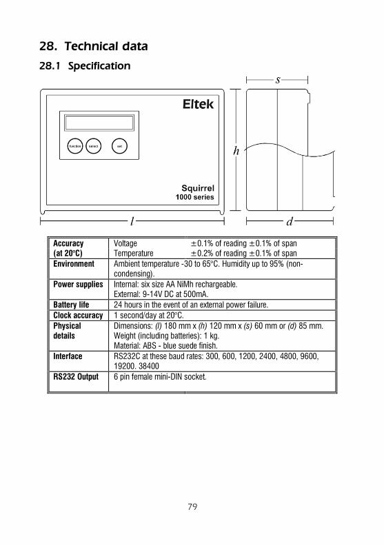
28. Technical data .............................................................................. 79 28.1 Specification ................................................................................ 79
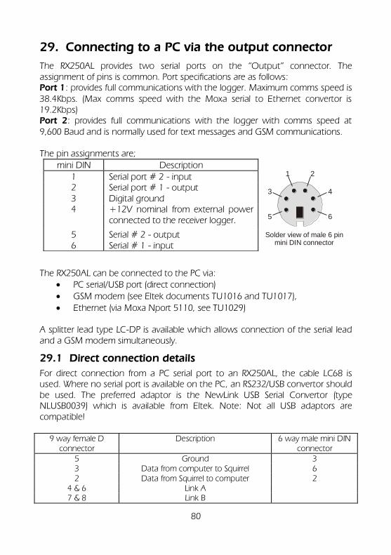
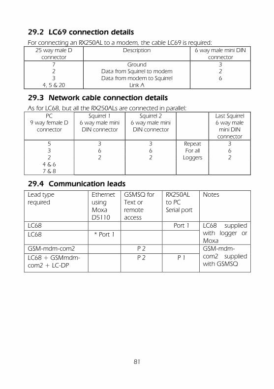
29. Connecting to a PC via the output connector.............................. 80 29.1 Direct connection details ............................................................. 80 29.2 LC69 connection details .............................................................. 81 29.3 Network cable connection details ............................................... 81 29.4 Communication leads ................................................................. 81
Declaration of Conformity ................................................................... 82 Manufacturer ......................................................................................... 82 Description of Equipment ...................................................................... 82 Applied Standards .................................................................................. 82
5
1. Introduction
This manual is for users who have purchased an Eltek GenII system comprising Eltek standard transmitters, standard repeater(s) and an RX250AL receiver/logger together with the Darca Plus or Darca Heritage software (hereon referred to as ‘Darca’). It assumes that the application is satisfied using this standard equipment and that a survey has been conducted to ensure that the radio range covers the site in question within the required margin of safety of performance. It assumes that the Darca software will be used to configure the RX250AL and transmitters and that the RX Config software will be used to set up repeaters if required. A section is included to explain how to configure the RX250AL from the button panel – especially useful in the field or if a PC is not available. (Further detail is available elsewhere – provide reference!) Quick survey methodology is included. Eltek has made all user instructions, manuals, data sheets and technical notes available on their website at www.eltekdataloggers.co.uk/support.html. Details of specific links are provided where applicable and any relevant information is also reprinted in this manual to assist the user. For clarity, some GenII products are not included in this manual. Such products include: RX250 variants, SC250 Secure data logger, RC250 variants and special transmitters (generally user specific). A section is included for standard accessories, identifications and use. A limited number of standard readily available probes and sensors are covered. 12-09-16
6
2. Principles of operation
2.1 Appropriate applications
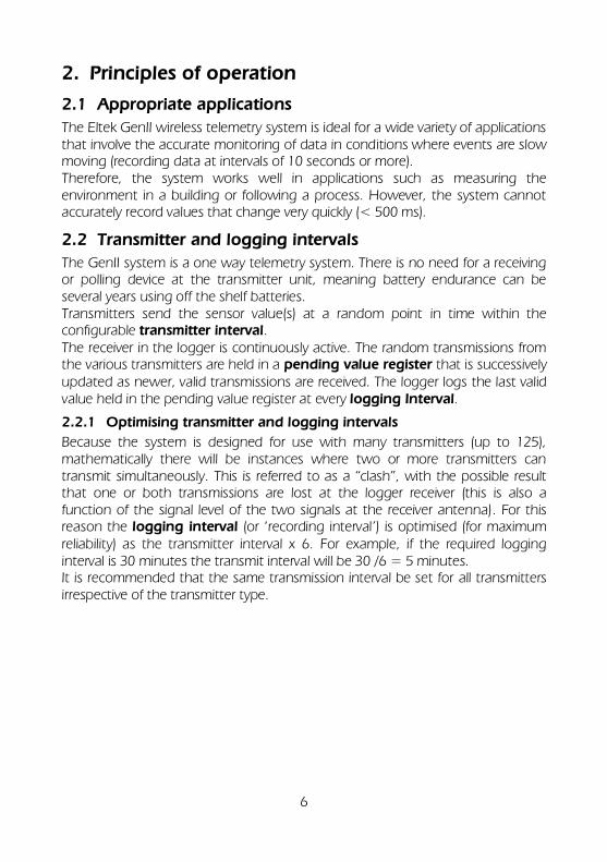
The Eltek GenII wireless telemetry system is ideal for a wide variety of applications that involve the accurate monitoring of data in conditions where events are slow moving (recording data at intervals of 10 seconds or more). Therefore, the system works well in applications such as measuring the environment in a building or following a process. However, the system cannot accurately record values that change very quickly (< 500 ms).
2.2 Transmitter and logging intervals
The GenII system is a one way telemetry system. There is no need for a receiving or polling device at the transmitter unit, meaning battery endurance can be several years using off the shelf batteries. Transmitters send the sensor value(s) at a random point in time within the configurable transmitter interval. The receiver in the logger is continuously active. The random transmissions from the various transmitters are held in a pending value register that is successively updated as newer, valid transmissions are received. The logger logs the last valid value held in the pending value register at every logging Interval.
2.2.1 Optimising transmitter and logging intervals
Because the system is designed for use with many transmitters (up to 125), mathematically there will be instances where two or more transmitters can transmit simultaneously. This is referred to as a “clash”, with the possible result that one or both transmissions are lost at the logger receiver (this is also a function of the signal level of the two signals at the receiver antenna). For this reason the logging interval (or ‘recording interval’) is optimised (for maximum reliability) as the transmitter interval x 6. For example, if the required logging interval is 30 minutes the transmit interval will be 30 /6 = 5 minutes. It is recommended that the same transmission interval be set for all transmitters irrespective of the transmitter type.
7
The following diagram illustrates the effect of a signal clash on the stored data:
Transmitter 1
Tx 1
Tx 2
Tx 3
p1
p1
p1
p2
p2
p2 p3
p3
p3
p4
p4
p4
p5
p5
p5
p6
p6
p6
p1
p1
p1
p2
p2
p2
p3
p4
p4
p4
p5
p5
p5
p6
clash
clash
Receiver / Logger
pending value register
Transmitter 2
Transmitter 3
p1 = packet 1
Tran
smit
ters
Transmit interval
Logging interval
p6
p5
p5
loggeddata
Note that for pulse transmitters the transmitted value is an accumulated count value, so if a transmission is lost the next valid transmission will include the pulses counted over the period including the ‘lost’ value.
2.2.2 Special cases
When designing a system, the number of transmitters (if high) and the logging interval must both be taken into account with respect to accepting some data loss over a period (week/months). Eltek can provide optimisation detail if required. Transmitter battery life must also be taken into consideration: if a short logging interval is required, using the 1:6 ratio may mean that the frequency of transmissions reduces transmitter battery life below an acceptable level. Again, Eltek can provide optimisation detail in these circumstances.
2.2.3 The sample interval
A further configurable interval, the sample interval, is provided on the logger. This is the rate at which the logger interrogates the pending value register for an alarm condition. Note that alarm conditions are set in the logger, not in the transmitter. For users who do not require the alarm feature the default sample interval should be the logging interval / 2. For users who need to be aware of alarm conditions promptly, the sample interval can be set to a minimum of 10 seconds (values less than 10 seconds can be used but please refer to Eltek for advice). For users who need to be aware of alarm conditions but can accept a delay between the condition and the notification, the sample interval can be set anywhere between the transmitter interval / 6 and 10 seconds.
8
3. Care and disposal of product
Care and Maintenance Please treat the all components with care. Do not expose the transmitter to any harsh environment where extremes of temperature, humidity or dust can be experienced. The transmitter must not be used in any hazardous rated environment. Do not disassemble the transmitter for any other reason than configuration or battery replacement. Some transmitter types do have a replaceable fuse should the battery be reverse connected. Do not expose the transmitter to water, rain or spillage. It is not waterproof. For operation in these environments a secondary waterproof enclosure is required and can be supplied by Eltek Do not abuse the transmitter by dropping, knocking or violent shaking. Rough handling could damage the transmitter. Do not operate the transmitter close to a receiving device – ensure there is a separation of 20cm. The transmitter power output is below the directive for devices used in a medical or hospital environment. For further details contact Eltek. Disposing of the product This electronic product is subject to the EU directive 2002/96/EC for Waste Electrical and Electronic Equipment (WEEE). As such it must not be disposed at a municipal waste collection point. Please refer to your local regulations for direction on how to dispose of this product in an environmentally responsible manner.
9
4. Note about RF performance
4.1.1 Improving Reception
Radio waves travel best in open unobstructed spaces. Aerials work best high up in open spaces. Unfortunately, it is rarely possible to have both of these criteria met! but these two statements should be kept in mind when installing the radio system. This will lead to the best performance of the system that can be obtained in a given situation. Note that metal objects and thick walls significantly attenuate radio signals. Reinforced concrete is a real signal killer as it can act like a metal screen. If a nearby source of interference contains frequency components in the band of the system, then the receiver will obviously be desensitised. This is especially true if the interference is stronger than the signal from a distant transmitter. Typical sources of interference are mobile phones, walkie-talkie type radios, Tetra police communication systems, computer equipment (especially older equipment) and anything with a radio transmitter in it, e.g. the components of a wireless security system.
4.1.2 Locating the Transmitters
For best range place the transmitter as high up as possible. Keep away from damp or metal clad walls, metal objects, cabling, pipes, etc. Also bear in mind that the fewer obstacles in the path to the receiver will give the greater range and reliability of the system.
4.1.3 Locating the RX250
The RX250AL is a single unit that combines both receiver and data logger. Locate the RX250AL central to the transmitters and clear of sources of radio interference. See 14.3.3 Improving reception above. Where range is not a problem the built in antenna supplied should be used and provides a very compact installation. Range can be very significantly improved using the optional LW-ANT/sma dipole antenna. This should be mounted as high as possible and away from sources of interference.
10
5. Accessories
5.1 Probes and sensors
Eltek RH and T detachable probe with 3m lead. (For longer lead refer to Eltek)
RHT10E
Leak sensing cable with 15m inactive section and 4m active section (other combinations POA) for GC60F
LC-Leak15/4
5.2 Antenna
Lightweight indoor/outdoor dipole antenna with 5m lead, SMA plug and mounting hardware
LW-ANT/SMA
5m coaxial antenna extension lead SMA to SMA ANT-EXT/SMA5m
¼ antenna on magnetic base with 1.8m lead UHF Flexi/Mag/sma
5.3 Modems
GSM Modem kit comprising modem, logger cable and external antenna on 2m lead
GSMSQ
GSM Modem kit for PC comprising modem, logger cable, AC power supply and antenna
GSMPC
GSM modem kits will be despatched preconfigured for UK and Euro markets, For other areas contact Eltek.
5.4 Ethernet
Moxa-D5110 Ethernet convertor with connecting cable and AC power supply
Moxa-D311
5.5 Wall bracket
Tamper-resistant wall bracket for all GenII product except the receiver logger.
WBG
2 piece wall bracket for receiver logger WBO
5.6 Leads
Serial to USB convertor lead RS232/USB
2M LC68 lead extender RS232/2M
5.7 Alarm
On-site audible and visual alarm for use with receiver loggers equipped with Alarm options.
OSA2
11
5.8 Connectors
Mini thermocouple connector type T (brown) MiniT
Mini thermocouple connector type K (green) MiniK
5.9 Weatherproof enclosure
Rugged outdoor (IP65) enclosure with built-in cradle for most transmitter types. specify transmitter type and accessories required with order - if in doubt contact Eltek
OD1 series
5.10 AC Transducer
AC100/240 transducer - provides an isolated contact closure when powered. Use with GD24 or GD34
EL-CC
5.11 Power supply
100-250VAC to 12VDC 15W power supply. Specify mains plug type with order (UK/Euro/US)
MP12U
100-250VAC to 12VDC 5.4W power supply (white). Specify mains plug type with order (UK/Euro)
MP12U5W
100-250VAC to 9VDC 5W supply (white). Specify mains plug type with order (UK/Euro)
MP9U5W
DIN rail mounting AC to 12VDC power supply for GD90A DRA18-12
Wire-in 24/12V to 9V regulator 24REG9
"Wired socket" is the mini Phoenix with cage screw terminals or equivalent with strain relief
12
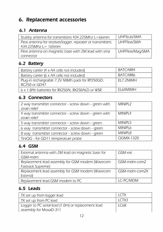
6. Replacement accessories
6.1 Antenna
Stubby antenna for transmitters 434.225Mhz L=66mm UHFStub/SMA
Flexi antenna for receiver/logger, repeater or transmitters 434.225Mhz L= 165mm
UHFFlexi/SMA
Flexi antenna on magnetic base with 2M lead with sma connector
UHFFlexi/Mag/SMA
6.2 Battery
Battery carrier (4 x AA cells not included) BATCARR4
Battery carrier (6 x AA cells not included) BATCARR6
Plug-in rechargeable 7.2V MiMh pack for RP250GD, RC250 or GD47
EL7.2NIMH
6 x 1.8Ah batteries for RX250Al, RX250ALD or WSR EL6XMIMH
6.3 Connectors
2 way transmitter connector - screw down - green with strain relief
MINIPL2
4 way transmitter connector - screw down - green with strain relief
MINIPL4
5 way transmitter connector - screw down - green MINIPL5
6 way transmitter connector - screw down - green MINIPL6
8 way transmitter connector - screw down - green MINIPL8
TiniQG - for GD11 temperature probe QGMX-1320
6.4 GSM
External antenna with 2M lead on magnetic base for GSM-mdm
GSM-ext
Replacement lead assembly for GSM modem (Wavecom Fastrack Supreme)
GSM-mdm-com2
Replacement lead assembly for GSM modem (Wavecom Extend)
GSM-mdm-com2X
Replacement lead GSM modem to PC LC-PC/MDM
6.5 Leads
TX set up from logger lead LCTX
TX set up from PC lead LCTX3
Logger to PC serial lead (1.0m) or replacement lead assembly for MoxaD-311
LC68
13
Splitter lead, allows access to both serial ports LCDP
6.6 TMET
IP65 outdoor enclosure with pole mount bracket for use with TMET only
WBT
Pole mounting bracket Skye or Kipp and Zonen pyranometers
PyrBkt
6.7 Power supply
DIN rail mounting AC to 12VDC power supply (For GD40A)
DRA18-12
14
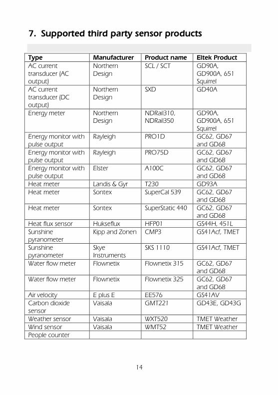
7. Supported third party sensor products
Type Manufacturer Product name Eltek Product AC current transducer (AC output)
Northern Design
SCL / SCT GD90A, GD900A, 651 Squirrel
AC current transducer (DC output)
Northern Design
SXD GD40A
Energy meter Northern Design
NDRail310, NDRail350
GD90A, GD900A, 651 Squirrel
Energy monitor with pulse output
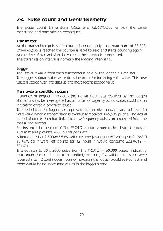
Rayleigh PRO1D GC62, GD67 and GD68
Energy monitor with pulse output
Rayleigh PRO75D GC62, GD67 and GD68
Energy monitor with pulse output
Elster A100C GC62, GD67 and GD68
Heat meter Landis & Gyr T230 GD93A
Heat meter Sontex SuperCal 539 GC62, GD67 and GD68
Heat meter Sontex SuperStatic 440 GC62, GD67 and GD68
The RP250GD repeater is a self-contained mains operated data packet (GenII protocol only) repeater. The RP250GDS repeater additionally includes a built-in switchable loudspeaker for survey applications. RP250GD Repeater features: An LCD to view activity and status of transmitters in operation Received Signal Strength Indication (RSSi) of incoming transmitter data
(chevron bar) Using the RepConf, Repeater Configuration software you can: Authorise transmitters you want to be repeated Compensate for systems requiring multiple repeaters Conduct a radio survey
8.1 Power requirements
The repeater requires permanent AC mains connection. Use only the AC power supply provided. When powered the red LED on the top of the unit will flash. Built-in Ni-Mh batteries provide up to 3 days standby in the event of power failure. A fully discharged battery is normally charged in 72 hours.
When you first receive the RP250GD the display will read OFF The display will switch to working mode when the MP12U power supply is
connected or by activating the concealed switch if the batteries are suitably charged.
If you remove the MP12U power supply the unit will stay in working mode until the internal rechargeable batteries are exhausted. The display will then
read OFF. The repeater can be turned off by removing the MP12U power supply and activating the concealed switch under the small hole on the back of the unit using an unfurled paper clip or narrow screwdriver. The red LED will stop flashing
and the display will read OFF.
8.2 Product Specification
AC supply: 100 to 250V AC (Use only Eltek power supply type MP12U)
DC input: 12.5VDC Maximum current <70mA Battery endurance: typically 72 hours Freq. UHF (Europe): default is 434.225Mhz (other frequencies available – refer
to Eltek)
16
Freq. US: default is 914.5Mhz (other frequencies available – refer to Eltek)
Rx sensitivity: -117dbm (one chevron on signal strength bar) Tx RF power: 10mW Antenna connection: SMA socket Antenna - standard: ¼ wave whip (shipped with product) Antenna - alternative: Indoor/outdoor dipole, lead length 5M standard,
accessory from Eltek Ltd type LW-ANT/sma. The maximum recommended lead length is 10M.
Transmitter spec: to European spec EN300-200 Temperature Range: -10 to +55ºC Humidity: 95% non-condensing Environment: Indoor use only IP40. A secondary enclosure must be
used for outdoor use Connectors DC supply: 2.1mm concentric jack (male) Comms (serial): 3.5mm stereo jack (applicable up to serial number 8480)
– use with lead type LCTX3 6 pin mini din (applicable to serial number 8481 to
current) – use with lead type LC68 For the latest detailed RP250GD information see the document TU1007 – RP250GD user instructions (available online).
17
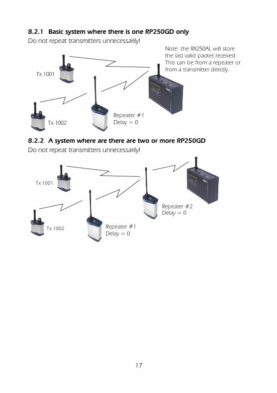
8.2.1 Basic system where there is one RP250GD only
Do not repeat transmitters unnecessarily! Note: the RX250AL will store the last valid packet received. This can be from a repeater or from a transmitter directly.
Repeater #1Delay = 0Tx 1002
Tx 1001
8.2.2 A system where are there are two or more RP250GD
Do not repeat transmitters unnecessarily!
Repeater #1Delay = 0
Tx 1002
Tx 1001
Repeater #2Delay = 0
18
8.2.3 For a system where multiple (tandem and radial pattern) RP250GD used:
Do not repeat transmitters unnecessarily!
Tx 1001
Tx 1002*
Tx 1003
Tx 1004
Repeater #2Delay = 0
Repeater #3Delay = 1
Repeater #1Delay = 0
Tip: Make a proposed system schematic as this will assist set up for the
various repeaters in the system. *TX1002 could be roving (mobile) around an area of coverage e.g
monitoring a pallet on a fork lift truck, such that Repeater 2 or Repeater 3 would repeat its transmission.
19
8.3 RSSI indicator (calibrated from serial number 7925 to current)
The 16 chevrons indicate the following Received Signal Strength Indication:
-
118 -116
-10
9
-10
6
-10
2
-10
0
-97
-94
-91
-88
-87
-84
-82
-79
-77
-73 dbm
At Risk Usable Ideal At Risk: Insufficient margin of safety to guarantee year-on-year performance Usable: Signal with a margin of safety to compensate for year on year changes
in the environment that could affect range i.e temperature and battery condition.
Ideal: Signal should be ideal at all times. (recommended for high system
reliability)
20
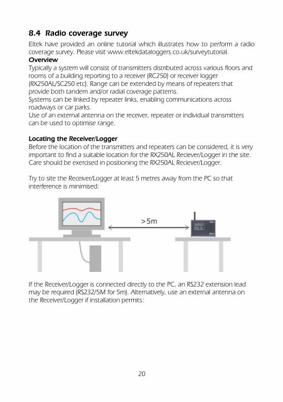
8.4 Radio coverage survey
Eltek have provided an online tutorial which illustrates how to perform a radio coverage survey. Please visit www.eltekdataloggers.co.uk/surveytutorial. Overview Typically a system will consist of transmitters distributed across various floors and rooms of a building reporting to a receiver (RC250) or receiver logger (RX250AL/SC250 etc). Range can be extended by means of repeaters that provide both tandem and/or radial coverage patterns. Systems can be linked by repeater links, enabling communications across roadways or car parks. Use of an external antenna on the receiver, repeater or individual transmitters can be used to optimise range. Locating the Receiver/Logger Before the location of the transmitters and repeaters can be considered, it is very important to find a suitable location for the RX250AL Reciever/Logger in the site. Care should be exercised in positioning the RX250AL Reciever/Logger. Try to site the Receiver/Logger at least 5 metres away from the PC so that interference is minimised:
If the Receiver/Logger is connected directly to the PC, an RS232 extension lead may be required (RS232/5M for 5m). Alternatively, use an external antenna on the Receiver/Logger if installation permits:
21
The Receiver/Logger should also be located clear of all other sources of radio interference. The following locations/materials will inhibit the performance of the system:
- Reinforced concrete - Metal cladding - Rooms that are constructed as Faraday cages - Moving machinery that changes position e.g. fork lift trucks, cranes
8.4.1 Using an RP250GD/RP250GDS to detect interference
Disconnect the antenna, and if no interference is present the RSSI bar on the unit's display should show 2 chevrons or less:
RP250GDS Only: Switch the audio toggle switch on (located on the top of the unit). You should hear white noise only. Connect the antenna, and if no interference is present the RSSI bar should display at most 6 chevrons:
22
RP250GDS Only: The audio should remain as white noise. If the signal is higher, this indicates that interference may be present. Interference can be generated by nearby electronic equipment. If the interference is from a nearby telemetry system then an alternative frequency for the final installation may be necessary. Should interference be detected and the origin cannot be found then advanced interference detection equipment will have to be used, e.g a radio frequency spectrum analyser. Refer to Eltek. Before installation a survey should be conducted.
8.5 Preparing the transmitter and repeater for the survey
8.5.1 Prepare the transmitter
Set the transmitter's transmit interval to 1 second: - Connect the survey transmitter to the PC with the cable supplied. - In Darca, open Transmitter Setup - Enter the correct COM port and click OK / Connect. - Enter 1 second as the Tx Interval and click Set Tx Interval.
8.5.2 Prepare the repeater
- Ensure the battery in the RP250GD/RP250GDS is fully charged. From fully drained, the battery takes 3-4 days to charge.
- Power on the repeater by briefly connecting the mains supply or by using the concealed button on the back.
- When a valid transmitter signal is received by the RP250GD/RP250GDS repeater, the transmitter serial number and RSSI (signal strength) will be displayed on the repeater's LCD display.
- If using an RP250GDS, the loudspeaker audio will be change from white noise to a short bark or croak. If the signal is strong the bark is clean and as the signal weakens the bark will become dominated by the white noise.
8.6 Carrying out the survey
- Create an initial site map/plan with the prospective transmitter positions located on it.
- Position the transmitter at the proposed Receiver location. - Take the RP250GD/RP250GDS to the first proposed transmitter location. - View the transmitter's serial number on the RP250GD/RP250GDS
display. - Check the signal strength is greater than 6 chevrons.
23
- If the strength is good, mark the survey map with a tick. - Continue checking, ticking transmitters when the signal is good. - Where the strength is not good, a repeater may be needed. - Find an appropriate location for a repeater, both in terms of signal
transmission and daily operation. - Move the survey transmitter to the proposed repeater location. - Check the remaining transmitter locations with the
RP250GD/RP250GDS. - Mark the location of the repeater and tick off transmitter locations when
surveyed. At the end of the survey you should have sufficient information to update the plan. There may be an opportunity to rationalise the plan (and perhaps reduce the number of repeaters) by possibly relocating repeaters. If this is the case the survey must be repeated to assure performance.
What can you expect in terms of range?
Our experience indicates communication across two floors (wood or reinforced concrete – and vertically inline separated) will be reliable. On the same floor expect more than 100M if simple prefabricated walling is used, more if the floor is open, and considerably less if steel or panelling of mesh lined chambers is present. Expect 500M for a repeater located in a window which is revealed to another repeater in a similar location. Always configure the repeater to pass the transmitter signal of those required and inhibit those not required. This reduces on-air activity leading to best system reliability.
24
9. Troubleshooting
“Why won’t it do that?” Having described the many things you can do with a RX250AL Squirrel, here are just a few operations that are not possible: - clear the memory while logging is in progress start logging when the memory is full start logging if no channels have been selected change date and time while logging change start date and time while logging change log and sample intervals while logging It is not possible to change the following either when there are readings stored in memory or when logging is in progress: Channel set up and ranges, including alarm levels Engineering unit ranges Memory size
25
10. Windows issues
Microsoft do not include the Windows help system with Windows Vista or Windows 7/10 by default. Darca and Darca Lite currently use this form of help. You can install the help system via Microsoft from the following location(s): Windows Vista: http://www.microsoft.com/downloads/details.aspx?familyid=6EBC
FAD9-D3F5-4365-8070-334CD175D4BB&displaylang=en
Windows 7: http://www.microsoft.com/en-gb/download/details.aspx?id=91
11.1 What is the best way to contact a logger remotely using GSM?
11.1.1 On the logger side Use the Eltek GSMSQ kit. This kit contains a GSM modem which arrives configured for use with Eltek telemetry or conventional Squirrel 1000 series data loggers. No adjustment is necessary. Packed in the box is the following:
Wavecom Extend modem Mounting tabs Logger to modem lead (type GSM-mdm-com2X) Antenna with 1.8m lead SMA connector User instructions
A SIM is NOT included. The SIM can be a low cost contract SIM as data is via the voice channel of the GSM network. The GSM modem is powered by the logger external supply. Therefore an external supply must be used with the logger, e.g. the MP12U power supply. If the external power fails the logger will continue to function but GSM functionality will be lost. The GSM modem is used to deliver text messages, contact the logger, make logger set-up changes and download data from the logger memory. To use the GSM modem for remote access via the GSM network and/or Alarm SMS texting, plug the supplied lead (type GSM-mdm-com2X) into the GSM modem and connect the other end to the "output" socket of the logger.
11.1.2 On the PC side It is recommended that the PC is equipped with a dedicated GSM modem (e.g. Eltek's GSMPC), which means that only the voice number is required for communication. If the PC is connected to the mobile network via a land line, an analog data number must be used. These data numbers are allocated by the SIM provider and are often difficult to obtain. When the PC is equipped with a dedicated GSM modem such as the GSMPC kit, however, then the remote logger GSM and PC GSM are communicating directly. This avoids the need for an analog data number altogether.
The Eltek GSMPC kit consists of the following: Wavecom Xtend modem Antenna Modem to PC serial lead (type LC-PC/MDM) AC to 12V DC power supply (type MPGSMextend)
A SIM is not included. The SIM can be a low cost contract SIM as data is via the voice channel of the GSM network.
27
Following the user instructions provided with the kit will quickly get you going.
11.2 What are Darca's System Requirements?
PC running Windows 98/ME/NT/2000/XP/Vista/7/8 CDROM drive (for installation) 16Mb RAM 8Mb free hard disk space for program Additional hard disk space for data VGA (or better) display One unused serial port (or USB slot if used with a USB to Serial
Converter) LC68 cable Eltek 1000 Series / RX250AL Squirrel
11.3 Why can't I establish a connection to the Squirrel from Darca?
There are a number of reasons that this problem could occur: The Squirrel does not have a power source (either batteries in the Squirrel’s battery compartment or an external mains power supply (MP12U). The Squirrel is not asleep. To correct this, select OUTPUT mode and wait 3 seconds for the Squirrel’s display to go blank. You are trying to connect to a networking Squirrel but have not selected the ‘Networked Squirrel’ option in the Settings > Communications dialog. If you are using a Modem connection:
The Modem is not connected to your PC. The Modem is not connected to your phone line. The Squirrel is not connected to the remote modem by an LC69 cable. Your Modem is not installed in Windows properly. Check the ‘Modems’
section of Control Panel. The remote Modem has not been configured correctly.
If you are using a Direct connection: The Squirrel is not connected to your PC by an LC68 cable. The LC68 cable is plugged into the wrong COM port – check your
settings in the Settings > Communications dialog.
The baud rate is set wrong in the Settings > Communications dialog. All 1000 series / RX250AL Squirrels manufactured since the year 2000 will communicate at 38400 baud or slower.
11.4 I have problem establishing a connection with a logger attached to a GSM modem.
Make sure the communication baud rate is set to 9600 in Darca. At other speeds
28
the logger may not 'wake up' reliably.
11.5 I have problems with connection reliability when using Darca with an instrument attached to a GSM modem.
Due to the nature of GSM you are more likely to get checksum errors on data from and to the logger. To prevent Darca from 'giving up' the connection, with an error like 'the logger could not be woken' you can increase the numbers of times Darca retries to 'wake up' the logger and the number of times it will retry a command to the logger. To do this go to settings then preferences and select the timing tab. Increase the wake up retries to 25 and the command retries to 10. This is particularly important if the logger is also scanning or logging the inputs very frequently.
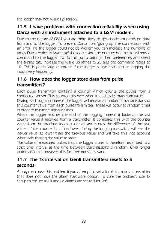
11.6 How does the logger store data from pulse transmitters?
Each pulse transmitter contains a counter which counts the pulses from a connected sensor. This counter rolls over when it reaches its maximum value. During each logging interval, the logger will receive a number of transmissions of this counter value from each pulse transmitter. These will occur at random times in order to minimise signal clashes. When the logger reaches the end of the logging interval, it looks at the last counter value it received from a transmitter. It compares this with the counter value from the previous logging interval and stores the difference of the two values. If the counter has rolled over during the logging interval, it will see the newer value as lower than the previous value and will take this into account when calculcating the value to store. The value of measured pulses that the logger stores is therefore never tied to a strict time interval as the time between transmissions is random. Over longer periods of time, however, this fact becomes irrelevant.
11.7 The Tx interval on GenII transmitters resets to 5 seconds
A bug can cause this problem if you attempt to set a local alarm on a transmitter that does not have the alarm hardware option. To cure the problem, use Tx setup to ensure all Hi and Lo alarms are set to 'Not Set'.
29
12. Contacting a logger via GSM
At the logger For the logger the modem kit required is the GSMSQ kit, which comprises a Wavecom Xtend modem, an antenna and a lead to connect the modem to the logger. A SIM is not included. Note that the modem is powered via this lead and gets its power from the MP12U (external power supply) connected to the logger. The Wavecom Xtend is preconfigured for the application. Following the user instructions provided with the kit will get you going quickly but you must have a valid SIM to hand. Using a landline modem at the PC end If the PC uses a landline modem to connect to the GSM network then the SIM for the GSMSQ must be equipped with an analogue data number. This is the dial up number that will be used in the Darca software running on the PC. An analogue data number is a requirement of the GSM network and allows the remote GSM unit (the GSMSQ) to identify itself as a data device only. Applying for the analogue data number can be difficult to obtain from your network provider. The analogue data number is linked to the voice number/barcode of the SIM you have acquired. Using a GSMPC at the PC end (recommended) If the PC is equipped with a dedicated GSM modem such as the one in the GSMPC kit from Eltek, the remote logger GSM and PC GSM are communicating directly. This avoids the need for an analogue data number altogether. Communications between the PC and logger are more reliable if a GSM PC is installed at the PC end. The GSMPC kit consists of a Wavecom Xtend modem, an antenna, a modem to PC serial lead and an AC to 12V DC power supply. A SIM is not included. Following the user instructions provided with the kit will quickly get you going. The SIM can be a low cost contract SIM as data is via the voice channel of the GSM network. .
30
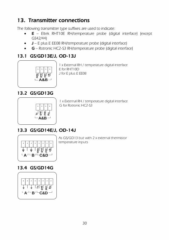
13. Transmitter connections
The following transmitter type suffixes are used to indicate: E – Eltek RHT10E RH/temperature probe (digital interface) (except
GS42/44) J – E plus E EE08 RH/temperature probe (digital interface)
G – Rotronic HC2-S3 RH/temperature probe (digital interface)
13.1 GS/GD13E/J, OD-13J
1 x External RH / temperature digital interfaceE for RHT10DJ for E plus E EE08
13.2 GS/GD13G
A&B
pw
r
Tx
Rx
gnd
1 x External RH / temperature digital interfaceG for Rotronic HC2-S3
13.3 GS/GD14E/J, OD-14J
As GS/GD13 but with 2 x external thermistor temperature inputs
13.4 GS/GD14G
A C&D
pw
r
Tx
Rx
gnd
B
31
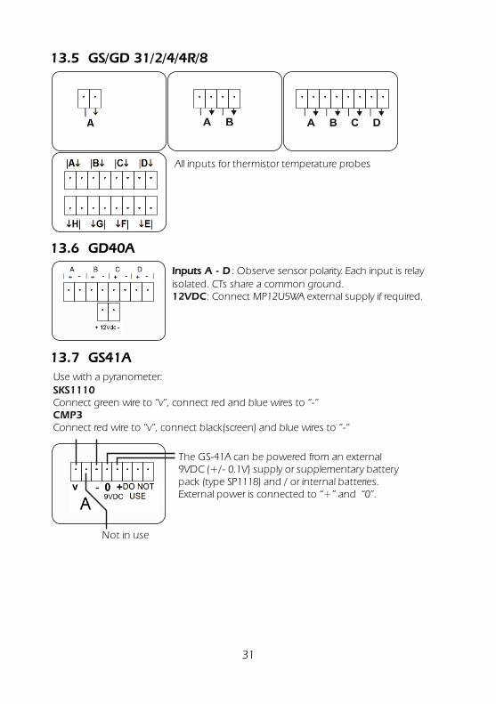
13.5 GS/GD 31/2/4/4R/8
All inputs for thermistor temperature probes
13.6 GD40A
Inputs A - D
12VDC
: Observe sensor polarity.
: Connect MP12U5WA external supply if required.
Each input is relay isolated. CTs share a common ground.
13.7 GS41A
Use with a pyranometer:
Connect green wire to “v”, connect red and blue wires to “-”SKS1110
CMP3Connect red wire to “v”, connect black(screen) and blue wires to “-”
The GS-41A can be powered from an external 9VDC (+/- 0.1V) supply or supplementary battery pack (type SP1118) and / or internal batteries. External power is connected to “+” and “0”.
Not in use
32
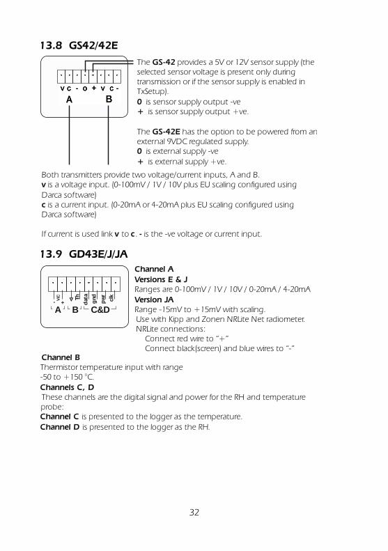
13.8 GS42/42E
Both transmitters provide two voltage/current inputs, A and B. is a voltage input. (0-100mV / 1V / 10V plus EU scaling configured using
Darca software) is a current input. (0-20mA or 4-20mA plus EU scaling configured using
Darca software)
If current is used link to .
v
c
v c - is the -ve voltage or current input.
The provides a 5V or 12V sensor supply (the selected sensor voltage is present only during transmission or if the sensor supply is enabled in TxSetup).
is sensor supply output -ve is sensor supply output +ve.
The has the option to be powered from an external 9VDC regulated supply.
is external supply -ve is external supply +ve.
GS-42
0+
GS-42E
0+
13.9 GD43E/J/JA
Channel B
Channels C, D
Channel CChannel D
Thermistor temperature input with range -50 to +150 °C.
These channels are the digital signal and power for the RH and temperature probe:
is presented to the logger as the temperature. is presented to the logger as the RH.
A C&D
pw
r
data
clk
gnd
B
V/C
- +
Th
Channel AVersions E & J
Version JARanges are 0-100mV / 1V / 10V / 0-20mA / 4-20mA
Range -15mV to +15mV with scaling. Use with Kipp and Zonen NRLite Net radiometer.NRLite connections:
Connect red wire to “+”Connect black(screen) and blue wires to “-”
33
13.10 GS44/GS44E/GS44H
The provide four inputs, A B C and D. Each is a voltage or current input (v c -). is voltage input, is current input. If current is used, link to . is the -ve
voltage or current input.
There is a on Connector 1 and a sensor supply output or FET switch on Connector 2. Connector 1: is sensor supply output -ve, is sensor supply output +ve Connector 2: is sensor supply output -ve or FET switch, is sensor supply output +ve or FET switch
There is an on Connector 1 and a sensor supply output or FET switch on Connector 2. Connector 1: is external 9VDC -ve, is external 9VDC +ve Connector 2: is sensor supply output -ve or FET switch, is sensor supply output +ve or FET switch
The provides four voltage inputs, A B C and D. There is also an external 9VDC supply input on Connector 1 and a sensor supply output or FET switch on Connector 2. Connector 1: is external 9VDC -ve, is external 9VDC +ve Connector 2: is sensor supply -ve or FET switch, is sensor supply +ve or FET switch
GS-44/44E
v c v c -
sensor supply output
0 + 0 +
external 9VDC supply input
0 +0 +
GS-44H bipolar single range
0 +0 +
GS-44
GS-44E
GS-44H[suffix letter]
Connector
13.11 GS44AVE
AVE indicates an averaged value is used at the point of transmission.Connector 1
is external 9VDC -ve (e.g MP9U), is external 9VDC +ve
Connector 2( is No connection, is No connection)
is a voltage input is a current input (with V to C for current range)
0+
0 +
vc- is the -ve voltage
34
13.12 GS/GD52
For 2 x 4 wire PT100
13.13 GS60
A B+-- +--+-- +--
2 x state inputs are provided: A and B.
An open input is transmitted as a “1"A closed input is transmitted as a “0"
Note: + is common. V open circuit is nominally V batt Input impedance is approximately 10Kohm.
13.14 GC62
Input A: ss o: : Signal : -ve
Signal : -ve oInput B:
2 x pulse input transmitter.
Range 6V to 9V DC (regulated).Power supply is MP9U from Eltek.
External power in
When external power is applied (and if greater than the internal battery voltage), the external power is used. If external power fails the internal batteries will power the transmitter.
13.15 GC62EX
Not used
Input A: ss o: : Signal : -ve
Signal : -ve oInput B:
2 x pulse input transmitter for compliance to IGEN (gas connection) requirements
GS41AV 1 x external air velocity (EplusE EE66/576) rolling average value
1 x calculated minimum
1 x calculated maximum
1 x instantaneous value (last value measured)
GS42 2 x external voltage or current 0-100mV
GS44 4 x external voltage or current 0-1V DC 0.25mV ±0.5mV
GS44AVE As GS44 but with averaging function
0-10V DC 2.50mV ±5mV
0-20mA DC ~5uA 20uA
4-20mA DC 0.05% 0.1%
GD43E 1 x external RH and temperature (RHT10E)
as GS13E
1 x voltage / current as GS42
1 x external thermistor temperature as GS31
GD43G 1 x external RH and temperature (Rotronic HC2-S3)
as GS13G
1 x voltage / current as GS42
1 x external thermistor temperature as GS31
GD43J 1 x external RH and temperature (EplusE EE68)
as GD13J
1 x voltage / current as GS42
1 x external thermistor temperature as GS31
GD43JScf 1 x external RH and temperature (EplusE EE68)
as GD13J
1 x voltage / current for pyranometer
0-30mV 0.1% ±30uV
1 x external thermistor temperature as GS31
GD47/GW47 1 x built-in RH and temperature as GD10
1 x built-in CO2 0-5000ppm 3% ±50ppm
1 x built-in 12VDC supply monitor
GS52/GD52 2 x 2 or 4 wire Pt100 temperature -100 to 200ºC 0.1ºC ±0.3ºC
GS52H 2 x 2 or 4 wire Pt100 temperature 0 to 300ºC 0.1ºC ±0.3ºC
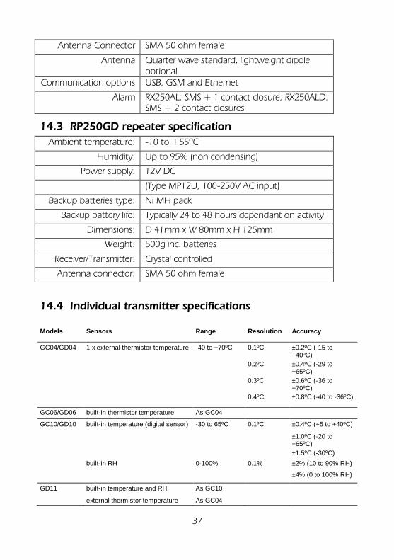
40
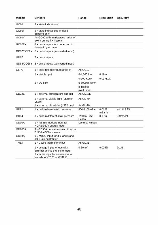
Models Sensors Range Resolution Accuracy
GC60 2 x state indications
GC60F 2 x state indications for flood sensors only
GC60Y As GC60 with mark/space ration of event during TX interval
GC62EX 2 x pulse inputs for connection to domestic gas meter
GC62/GC62a 2 x pulse inputs (/a inverted input)
GD67 7 x pulse inputs
GD68/GD68a 8 x pulse inputs (/a inverted input)
GL-70 1 x built-in temperature and RH As GC10
1 x visible light 0-4,000 Lux 0.1Lux
0-200 KLux 0.01KLux
1 x UV light 0-5000 mW/m²
0-10,000 µW/Lumen
GD72E 1 x external temperature and RH As GD13E
1 x external visible light (LS50 or LS70)
As GL-70
1 x external ultraviolet (LS70 only) As GL-70
GD81 1 x built-in barometric pressure 800-1100mBar 0.0122 mBar/bit
+/-1% FSS
GD84 1 x built-in differential air pressure -250 to +250 Pascal
0.1 Pa ±3Pascal
GD90A 1 x RS485 modbus input for NDRail350V energy meter
Up to 12 values
GD900A As GD90A but can connect to up to 6 NDRail350V meters
GD93A 1 x MBUS input for 3 x landis and gyr T230 heatmeter
TMET 1 x u type thermistor input As GD31
1 x voltage input for use with external device e.g. solarimeter
0-50mV 0.025% 0.1%
1 x serial input for connection to Vaisala WXT520 or WMT50
41
15. Thermocouple isolation and interference issues
To ensure accurate and reliable performance the following points should be understood and taken into consideration: Galvanic isolation is essential When using multiple non insulated thermocouple probes it is essential that full galvanic isolation exists between the probes. Failure to do so will create reading errors. Current loops When using thermocouple probes connected to a common transmitter which is powered from a source other than internal batteries, potential current loops can exist causing reading errors. If it is essential that the transmitter is powered externally, the AC power supply must be a type which has extremely low AC leakage current (such as medical grade types). It is preferred that only the Eltek MP12U or MP12U5W power supplies are used. In case of doubt, contact Eltek. Induced voltage interference When using thermocouples with long leads in the presence of electrical interference (e.g. welding equipment or heating control systems, especially oven furnace control systems) voltages can be induced into the thermocouple tip which will lead to reading errors. Ensure that thermocouples are not located close to electrical interference.
42
16. Configuring the logger using the buttons
The operating buttons allow the setup of many of the major functions of the logger and the setup of some of the functions of assigned transmitters. Functions that are not accessible from the operating buttons include the setting of EU units on a logger channel and full range selection on a transmitter. Connecting the logger and transmitters to a PC and using the Darca software application provides complete and comprehensive logger and transmitter setup functionality.
function selects the function. select selects the channel or sub function. set is used to change any of the settings.
To switch the datalogger on, press and hold function. To switch it off, leave in LOG or OUTPUT function for a few seconds. If the datalogger is left on in any other function, it will automatically switch off after 4 minutes.
43
17. Setting up transmitters from the RX250AL
(The preferred method is to setup the system using the Darca software as not all options are available from the logger setup).
17.1 Initial Setup
17.1.1 Connections
Power the RX250AL using only the MP12U power supply. Note the polarity of the 12VDC regulator power-in connector where –ve is input and +ve is output.
17.1.2 Transmitter ID
Each transmitter has a unique serial number displayed on the screen at power up) which is used as an identifying code by the RX250AL. It is shown on the RX250AL display during transmitter related functions, such as Channel Setup. Every transmitted value is accompanied by this number.
17.2 Connecting transmitters to the RX250AL
An LC-TX programming lead is supplied to connect each transmitter to the RX250AL ‘output’ connector for configuration purposes. The LC-TX has a male 6-pin mini-DIN at one end and a 3.5mm stereo jack plug on the other.
Alternatively Darca can be used to set-up transmitters. Each transmitter must be connected in turn to the RX250AL to configure the channels and set the transmission interval. This process simultaneously configures both the RX250AL and the transmitter. The RX250AL can be used to program each of the transmitters with the channel set-up, humidity calibration information, and the transmission interval. Settings are stored in the transmitter in non-volatile memory. There are three aspects to the set-up: 1. The transmission interval. 2. Selection of the channels to be transmitted. 3. The calibration of the sensors. Settings can only be changed if the RX250AL is not logging and has had its memory cleared. After connecting the battery, the transmitter will be in one of two states:
Unconfigured – Transmitters LEDs should be flashing every 8 seconds. Configured – A brief flash will occur at the point of transmission.
Now connect the LC-TX. Plug the 6-pin mini-DIN in to the RX250AL socket labelled “output” and the 3.5mm jack into the socket located on the PCB within the transmitter. This is only accessible if the bottom cover of the transmitter is
44
removed by unscrewing the two Pozi head screws. The battery pack can now be carefully withdrawn, but left connected.
17.3 Setting the logging and transmission Interval
The interval function (described in Section 3.5) is used to set the logging interval of the RX250AL. Another page in the “INT mode” enables the transmission intervals in the transmitters to be changed. After connecting a transmitter, pressing the select button enters this sub-function of “INT mode”, “INT TX” will display the interval that is currently set in the transmitter that is connected to the RX250AL
I N T T X - 1 2 3 4 t x - i n t 0 : 0 5 : 0 0
If the RX250AL fails to find a transmitter connected to the Squirrel, the display will show the following:
I N T c o n n e c t T X
If this is displayed even with a transmitter connected, then the connections should be checked, as should the state of the battery in the transmitter. The default value of the transmission interval is 5 minutes, which is the recommended value for 30 minute logging interval. Other logging and Tx intervals can be used; however, a 6:1 logging to Tx interval ratio is recommended. The transmission interval can be changed in exactly the same way as the log or scan interval is changed in the Squirrel. Once the required value is shown on the display, the function button must be pressed to transfer the new setting into the transmitter. The display is then updated to reflect the new value in the transmitter. Pressing the function button again will move the RX250AL into the next function, as usual. Alternatively, if there are a number of transmitters to configure, another may be connected at this point. The display is automatically updated to show the new transmitter’s serial number and transmit interval. It is worth mentioning that the transmission interval is in fact an ‘average’ transmission interval. The transmission will occur at a random point during each transmit interval. This minimises the chances of transmissions from two or more transmitters systematically crashing into each other. It also means that it can appear to an observer that the gap between two transmissions can be almost as much as twice the transmit interval. In this case, a transmitter would be transmitting at the very beginning of one interval and at the very end of the next.
45
17.4 TX Battery and Reliability
The TX battery and Reliability function can be found after the Channel Setup function. As with some of the other functions, its behaviour depends on whether a transmitter is connected to the RX250AL with the programming lead. If no transmitter is connected, the RX250AL will display a summary of each transmitter when the select button is pressed:
T X - 1 2 3 4 5 7 % 9 3 % r e l
Pressing the select button again will show a different transmitter (assuming more than one has been set-up for the RX250AL). The order in which the transmitters are shown in this function reflects the sequence in which they were configured on the RX250AL. If the RX250AL has not yet received a battery reading from any particular transmitter, then the display will show a series of dashes instead of the battery voltage:
T X - 1 2 3 4 0 - - - - 9 3 % r e l
As soon as the RX250AL receives information on the level of the battery, it will be displayed here. The reliability figure on the right-hand side of the display is there to give an idea of how well the transmitted data packets are being received by the RX250AL. Note that before logging starts the reliability value is unavailable, so it is replaced with a series of dashes:
T X - 1 2 3 4 0 5 7 % - - - % r e l
The reliability value is expressed as a percentage of how many transmissions were successful. It is calculated by comparing the number of packets successfully received by the RX250AL during the last logging interval with the number of packets expected, based on the transmission interval of the transmitter. This figure is then subject to a rolling average, so it is only after a few record intervals that the figure is representative of the reception reliability of the transmitter. A typical system, where the transmitters are well within the operating range, and where there aren’t a large number of transmitters on short intervals, should show reliability figures in the nineties. Should the RX250AL report a lower value for any transmitter, then this is an
46
indication that the transmitter should be moved to a different location to improve reception at the RX250AL. Sometimes a small move will improve the reception greatly.
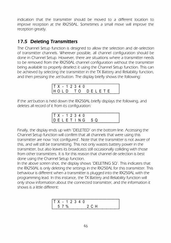
17.5 Deleting Transmitters
The Channel Setup function is designed to allow the selection and de-selection of transmitter channels. Wherever possible, all channel configuration should be done in Channel Setup. However, there are situations where a transmitter needs to be removed from the RX250AL channel configuration without the transmitter being available to properly deselect it using the Channel Setup function. This can be achieved by selecting the transmitter in the TX Battery and Reliability function, and then pressing the set button. The display briefly shows the following:
T X - 1 2 3 4 0 H O L D T O D E L E T E
If the set button is held down the RX250AL briefly displays the following, and deletes all record of it from its configuration:
T X - 1 2 3 4 0 D E L E T I N G S Q
Finally, the display ends up with ‘DELETED’ on the bottom line. Accessing the Channel Setup function will confirm that all channels that were using this transmitter are now ‘not configured’. Note that the transmitter is not aware of this, and will still be transmitting. This not only wastes battery power in the transmitter, but also leaves its broadcasts still occasionally colliding with those from other transmitters. It is for this reason that channel de-selection is best done using the Channel Setup function. In the above screen shot, the display shows ‘DELETING SQ’. This indicates that the RX250AL is only deleting the settings in the RX250AL for this transmitter. This behaviour is different when a transmitter is plugged into the RX250AL with the programming lead. In this instance, the TX Battery and Reliability function will only show information about the connected transmitter, and the information it shows is a little different:
T X - 1 2 3 4 0 5 7 % 2 C H
47
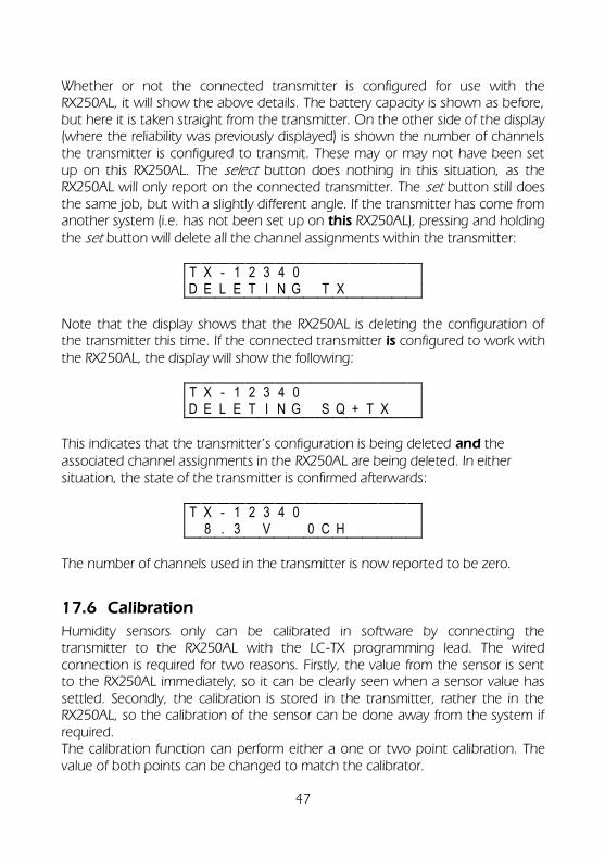
Whether or not the connected transmitter is configured for use with the RX250AL, it will show the above details. The battery capacity is shown as before, but here it is taken straight from the transmitter. On the other side of the display (where the reliability was previously displayed) is shown the number of channels the transmitter is configured to transmit. These may or may not have been set up on this RX250AL. The select button does nothing in this situation, as the RX250AL will only report on the connected transmitter. The set button still does the same job, but with a slightly different angle. If the transmitter has come from another system (i.e. has not been set up on this RX250AL), pressing and holding the set button will delete all the channel assignments within the transmitter:
T X - 1 2 3 4 0 D E L E T I N G T X
Note that the display shows that the RX250AL is deleting the configuration of the transmitter this time. If the connected transmitter is configured to work with the RX250AL, the display will show the following:
T X - 1 2 3 4 0 D E L E T I N G S Q + T X
This indicates that the transmitter’s configuration is being deleted and the associated channel assignments in the RX250AL are being deleted. In either situation, the state of the transmitter is confirmed afterwards:
T X - 1 2 3 4 0 8 . 3 V 0 C H
The number of channels used in the transmitter is now reported to be zero.
17.6 Calibration
Humidity sensors only can be calibrated in software by connecting the transmitter to the RX250AL with the LC-TX programming lead. The wired connection is required for two reasons. Firstly, the value from the sensor is sent to the RX250AL immediately, so it can be clearly seen when a sensor value has settled. Secondly, the calibration is stored in the transmitter, rather the in the RX250AL, so the calibration of the sensor can be done away from the system if required. The calibration function can perform either a one or two point calibration. The value of both points can be changed to match the calibrator.
48
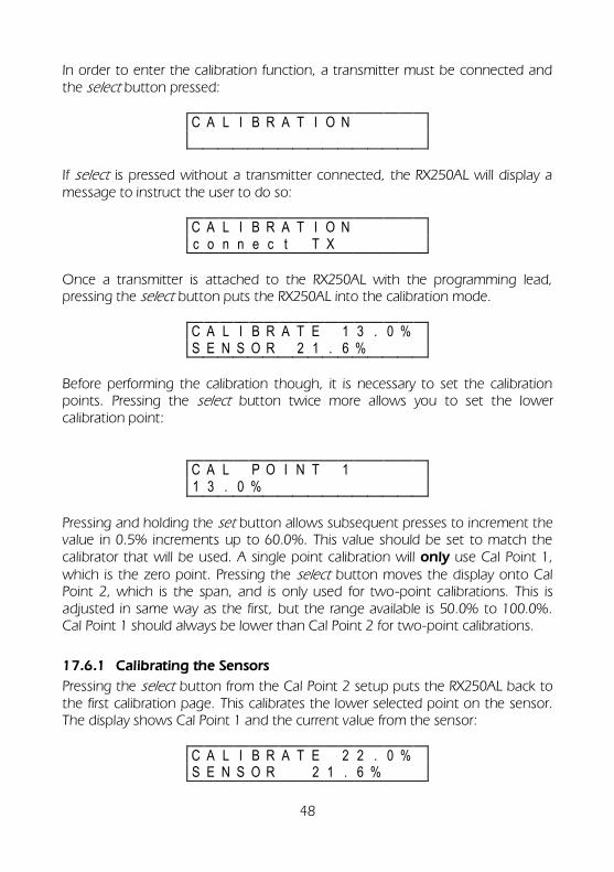
In order to enter the calibration function, a transmitter must be connected and the select button pressed:
C A L I B R A T I O N
If select is pressed without a transmitter connected, the RX250AL will display a message to instruct the user to do so:
C A L I B R A T I O N c o n n e c t T X
Once a transmitter is attached to the RX250AL with the programming lead, pressing the select button puts the RX250AL into the calibration mode.
C A L I B R A T E 1 3 . 0 % S E N S O R 2 1 . 6 %
Before performing the calibration though, it is necessary to set the calibration points. Pressing the select button twice more allows you to set the lower calibration point:
C A L P O I N T 1 1 3 . 0 %
Pressing and holding the set button allows subsequent presses to increment the value in 0.5% increments up to 60.0%. This value should be set to match the calibrator that will be used. A single point calibration will only use Cal Point 1, which is the zero point. Pressing the select button moves the display onto Cal Point 2, which is the span, and is only used for two-point calibrations. This is adjusted in same way as the first, but the range available is 50.0% to 100.0%. Cal Point 1 should always be lower than Cal Point 2 for two-point calibrations.
17.6.1 Calibrating the Sensors
Pressing the select button from the Cal Point 2 setup puts the RX250AL back to the first calibration page. This calibrates the lower selected point on the sensor. The display shows Cal Point 1 and the current value from the sensor:
C A L I B R A T E 2 2 . 0 % S E N S O R 2 1 . 6 %
49
The sensor should be placed in the calibration device. Once the reading has stabilised, the set button should be pressed and held to set the sensor to read the value of Cal Point 1 for the present input. If the calibration is too far out, the RX250AL displays ‘CAN’T SET’. This may be caused by setting the wrong value for the Cal Point, by putting the sensor in the wrong solution, or it could mean that the sensor element needs replacing. This can be done by the user, after which the calibration must performed again. A two-point calibration can be performed by repeating the above procedure for Cal Point 2. Pressing select moves the RX250AL onto the second calibration point.
50
18. The functions of the RX250AL datalogger
18.1 LOG
Used to start and stop logging. In addition, this function displays the number of readings already stored in the memory (used), and the number of readings that may be stored in the remaining memory (free). All the readings stored in memory may be erased in this function. In addition, this function will allow you to display how many separate runs have been recorded.
18.2 METER
Displays the value of the channels that have been selected, in the appropriate units.
18.3 TIME / date
Displays the real time and date on two lines. The time increments every second.
18.4 START time / date
This option allows you to set a future time and date at which logging will start.
18.5 INT log / sample (logging/sampling interval)
The interval function is used to set the time intervals at which readings are taken and stored in memory. The logging interval can be set between 1 second and 24 hours in 1-second increments. The second line is used to set the time intervals at which inputs are sampled for the purpose of checking whether an alarm condition has occurred.
18.6 OUTPUT
Used for output of recorded data to a computer. During downloading of data, the LCD displays the number of blocks to be downloaded and this is decremented after each successful transmission of a block. No baud rate setting is required as it is automatically selected.
18.7 MODE
There is only one available logging mode: ‘interval’.
18.8 CHANNEL SETUP
Used to select the channels from which you require data to be recorded.
18.9 STAT (status and other functions)
This function displays the following status information concerning the datalogger: (Firmware version 7.3 onwards)
51
a) Internal battery voltage / remaining battery backup b) External supply voltage c) Memory size (with the ability to change memory size in 1K increments) d) Setup (transmitter setup) - can be enabled / disabled e) Max chans – can be set f) Network option – can be enabled / disabled g) Check GSM – to check GSM modem functionality/ RSSI, signal strength h) Send SMS – to send a test SMS message i) Stat OK message – daily or weekly ( Not available for Firm ware versions
before 7.3) j) Start delay (needs to be on for Darca Heritage) k) Version of logger software l) Serial no
52
19. How to start logging using the operating buttons
19.1 Set time/date
The real time and date are displayed on two lines. The time is set in the format HH:MM:SS. and the date default format is DD/MM/YY. Press function until the display shows: -
T I M E 1 0 : 4 2 : 5 9 d a t e 2 5 / 1 2 / 9 4
Press set and the following prompt appears: -
T I M E 1 0 : 4 3 : 1 1 H O L D T O C H A N G E
Hold set button and cursor will appear: - (the clock will stop)
T I M E 1 0 : 4 3 : 1 7 d a t e 2 5 / 1 2 / 9 4
Press select to move cursor: -
T I M E 1 0 : 4 3 : 1 7 d a t e 2 5 / 1 3 / 9 4
Press set to change value: -
T I M E 1 0 : 4 6 : 1 7 d a t e 2 5 / 1 2 / 9 4
Press function when settings are correct: - (cursor will disappear and clock will restart with new settings).
T I M E 1 0 : 4 6 : 1 9 d a t e 2 5 / 1 2 / 9 4
If an invalid data is entered, the display changes the settings to the nearest valid time/date.
19.2 Select logging interval
The logging interval can be set between 1 second and 24 hours in 1-second
53
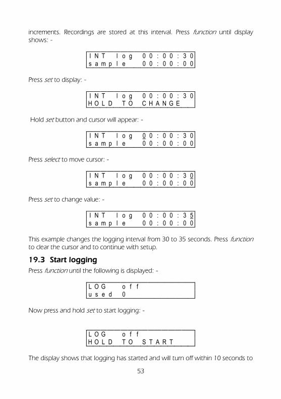
increments. Recordings are stored at this interval. Press function until display shows: -
I N T l o g 0 0 : 0 0 : 3 0 s a m p l e 0 0 : 0 0 : 0 0
Press set to display: -
I N T l o g 0 0 : 0 0 : 3 0 H O L D T O C H A N G E
Hold set button and cursor will appear: -
I N T l o g 0 0 : 0 0 : 3 0 s a m p l e 0 0 : 0 0 : 0 0
Press select to move cursor: -
I N T l o g 0 0 : 0 0 : 3 0 s a m p l e 0 0 : 0 0 : 0 0
Press set to change value: -
I N T l o g 0 0 : 0 0 : 3 5 s a m p l e 0 0 : 0 0 : 0 0
This example changes the logging interval from 30 to 35 seconds. Press function to clear the cursor and to continue with setup.
19.3 Start logging
Press function until the following is displayed: -
L O G o f f u s e d 0
Now press and hold set to start logging: -
L O G o f f H O L D T O S T A R T
The display shows that logging has started and will turn off within 10 seconds to
54
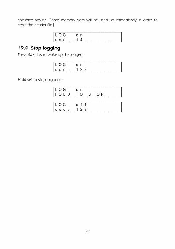
conserve power. (Some memory slots will be used up immediately in order to store the header file.)
L O G o n u s e d 1 4
19.4 Stop logging
Press function to wake up the logger: -
L O G o n u s e d 1 2 3
Hold set to stop logging: -
L O G o n H O L D T O S T O P
L O G o f f u s e d 1 2 3
55
20. More about the functions of the datalogger
20.1 The LOG function
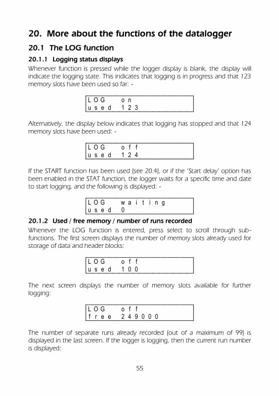
20.1.1 Logging status displays
Whenever function is pressed while the logger display is blank, the display will indicate the logging state. This indicates that logging is in progress and that 123 memory slots have been used so far: -
L O G o n u s e d 1 2 3
Alternatively, the display below indicates that logging has stopped and that 124 memory slots have been used: -
L O G o f f u s e d 1 2 4
If the START function has been used (see 20.4), or if the ‘Start delay’ option has been enabled in the STAT function, the logger waits for a specific time and date to start logging, and the following is displayed: -
L O G w a i t i n g u s e d 0
20.1.2 Used / free memory / number of runs recorded
Whenever the LOG function is entered, press select to scroll through sub-functions. The first screen displays the number of memory slots already used for storage of data and header blocks:
L O G o f f u s e d 1 0 0
The next screen displays the number of memory slots available for further logging:
L O G o f f f r e e 2 4 9 0 0 0
The number of separate runs already recorded (out of a maximum of 99) is displayed in the last screen. If the logger is logging, then the current run number is displayed:
56
L O G o f f r u n 3
20.1.3 Start/stop logging
If you have just unpacked your datalogger and have not previously used this model then please go to section l). Whenever you first enter the LOG function you can press and hold set to start and stop logging: -
L O G o f f u s e d 1 2 3 4 5
L O G o n u s e d 1 2 3 4 5
N.B. you can only start and stop logging when the display shows either of these screens.
20.1.4 How to clear the memory
The procedure for clearing the memory has been designed to reduce the risk of the user accidentally clearing the memory. It is not possible to clear the memory while either logging or waiting to log. It is only possible to clear the memory using the following sequence: Press function to wake up the datalogger and press select within 10 seconds to obtain either of the following displays: -
L O G o f f f r e e 1 2 3 4 5
L O G o f f r u n 3
Now you can clear the memory by pressing and holding set for 2 seconds: -
L O G o f f H O L D T O C L E A R
20.2 The METER function
This displays the value of the selected channel using the currently selected range for that channel. As soon as you enter the METER function, the display will show the value of the first channel selected and these values will be updated every second. The RX250AL Squirrel has two methods of displaying values in the Meter
57
function: 1. If the transmitter is connected directly to the RX250AL, the current value for
each channel will be displayed. 2. If the transmitter is not connected, then the display will show the last
received value for that channel. It is possible that in this situation there may not have been any received values from the transmitter. The RX250AL would then display the following:
M E T E R c h 1 - - - - ° C
This simply indicates that there have not yet been any readings from that channel received by the RX250AL. This will be replaced with a value as soon as the RX250AL receives one. If a transmitter is plugged in that hasn’t (yet) been set up in the Channel Set-up function of the RX250AL, the display will show the following:
M E T E R u n k n o w n T X
In order to meter this transmitter, it would be necessary to assign it to a channel in the Channel Setup function.
20.3 The TIME and date function
This displays the real time and date on two lines. The time clock is in a 24 hour format (HH:MM:SS). Please see section 19.1 for details of how to set the time and date. Although invalid times and dates are allowed to be set, when function is pressed, the entries are validated. The logger modifies the entries to the nearest valid setting and displays a warning that the initial entries were invalid. For example, the following would occur in UK date format i.e. DD/MM/YY: -
T I M E 1 0 : 4 3 : 1 7 d a t e 2 5 / 1 3 / 9 4
T I M E 1 0 : 4 3 : 1 7 I N V A L I D - C H E C K !
T I M E 1 0 : 4 3 : 1 7 d a t e 2 5 / 1 2 / 1 3
58
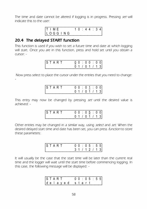
The time and date cannot be altered if logging is in progress. Pressing set will indicate this to the user:
T I M E 1 0 : 4 4 : 3 4 L O G G I N G
20.4 The delayed START function
This function is used if you wish to set a future time and date at which logging will start. Once you are in this function, press and hold set until you obtain a cursor: -
S T A R T 0 0 : 0 0 : 0 0 0 1 / 0 1 / 1 3
Now press select to place the cursor under the entries that you need to change: -
S T A R T 0 0 : 0 1 : 0 0 0 1 / 0 1 / 1 3
This entry may now be changed by pressing set until the desired value is achieved: -
S T A R T 0 0 : 0 5 : 0 0 0 1 / 0 1 / 1 3
Other entries may be changed in a similar way, using select and set. When the desired delayed start time and date has been set, you can press function to store these parameters:
S T A R T 0 0 : 0 5 : 5 5 3 1 / 1 2 / 1 3
It will usually be the case that the start time will be later than the current real time and the logger will wait until the start time before commencing logging. In this case, the following message will be displayed: -
S T A R T 0 0 : 0 5 : 5 5 d e l a y e d s t a r t
59
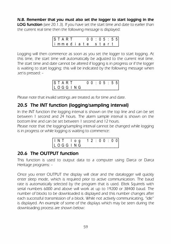
N.B. Remember that you must also set the logger to start logging in the LOG function (see 20.1.3). If you have set the start time and date to earlier than the current real time then the following message is displayed:
S T A R T 0 0 : 0 5 : 5 5 i m m e d i a t e s t a r t
Logging will then commence as soon as you set the logger to start logging. At this time, the start time will automatically be adjusted to the current real time. The start time and date cannot be altered if logging is in progress or if the logger is waiting to start logging; this will be indicated by the following message when set is pressed: -
S T A R T 0 0 : 0 5 : 5 5 L O G G I N G
Please note that invalid settings are treated as for time and date.
20.5 The INT function (logging/sampling interval)
In the INT function the logging interval is shown on the top line and can be set between 1 second and 24 hours. The alarm sample interval is shown on the bottom line and can be set between 1 second and 12 hours. Please note that the logging/sampling interval cannot be changed while logging is in progress or while logging is waiting to commence:
I N T l o g 1 2 : 0 0 : 0 0 L O G G I N G
20.6 The OUTPUT function
This function is used to output data to a computer using Darca or Darca Heritage programs: - Once you enter OUTPUT the display will clear and the datalogger will quickly enter sleep mode, which is required prior to active communication. The baud rate is automatically selected by the program that is used. Eltek Squirrels with serial numbers 6000 and above will work at up to 19200 or 38400 baud. The number of blocks to be downloaded is displayed and this number changes after each successful transmission of a block. While not actively communicating, “idle” is displayed. An example of some of the displays which may be seen during the downloading process are shown below:
60
O U T P U T 9 6 0 0 b a u d c o m m s b l o c k 6
O U T P U T 9 6 0 0 b a u d i d l e
O U T P U T 9 6 0 0 b a u d c o m m s b l o c k 5
The number of blocks transmitted will decrement until the display clears to indicate that all the data have been transferred. Please note that downloading of data can be achieved while logging is in progress.
20.7 The MODE function
The settings in the mode function are for information purposes only and cannot be changed.
20.8 The CHANNEL SETUP function
This is used to select the channels and set the range for each channel. This function also displays how many channels have been selected to record. The RX250AL must be connected to a transmitter with the LC-TX programming lead when setting up channels. Entering Channel Set-up for the first time will show this on the display:
C H A N N E L S E T U P 0 u s e d
The RX250AL channel is selected in the normal way using the select button:
C H 1 n o t c o n f i g u r e d
Pressing the set button steps through the available channels of the transmitter:
C H 1 T X - 1 2 3 4 A - 5 0 / 1 5 0 ° C
Here, the RX250AL is showing the current channel configuration for channel 1. In the middle of the top line of the display, the transmitter number is displayed. The ‘A’ on the right hand side of the display shows the selected channel within the transmitter. Note that the channels of the transmitters are assigned letters to prevent them being confused with the numbers of the RX250AL channels.
61
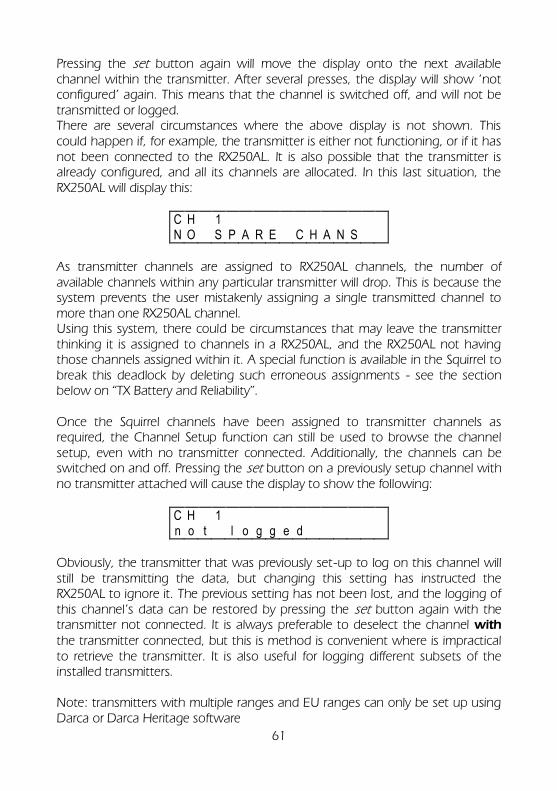
Pressing the set button again will move the display onto the next available channel within the transmitter. After several presses, the display will show ‘not configured’ again. This means that the channel is switched off, and will not be transmitted or logged. There are several circumstances where the above display is not shown. This could happen if, for example, the transmitter is either not functioning, or if it has not been connected to the RX250AL. It is also possible that the transmitter is already configured, and all its channels are allocated. In this last situation, the RX250AL will display this:
C H 1 N O S P A R E C H A N S
As transmitter channels are assigned to RX250AL channels, the number of available channels within any particular transmitter will drop. This is because the system prevents the user mistakenly assigning a single transmitted channel to more than one RX250AL channel. Using this system, there could be circumstances that may leave the transmitter thinking it is assigned to channels in a RX250AL, and the RX250AL not having those channels assigned within it. A special function is available in the Squirrel to break this deadlock by deleting such erroneous assignments - see the section below on “TX Battery and Reliability”. Once the Squirrel channels have been assigned to transmitter channels as required, the Channel Setup function can still be used to browse the channel setup, even with no transmitter connected. Additionally, the channels can be switched on and off. Pressing the set button on a previously setup channel with no transmitter attached will cause the display to show the following:
C H 1 n o t l o g g e d
Obviously, the transmitter that was previously set-up to log on this channel will still be transmitting the data, but changing this setting has instructed the RX250AL to ignore it. The previous setting has not been lost, and the logging of this channel’s data can be restored by pressing the set button again with the transmitter not connected. It is always preferable to deselect the channel with the transmitter connected, but this is method is convenient where is impractical to retrieve the transmitter. It is also useful for logging different subsets of the installed transmitters. Note: transmitters with multiple ranges and EU ranges can only be set up using Darca or Darca Heritage software
62
20.9 Alarms
High and low alarms are individually configurable on each channel. The alarm output is asserted and the relay contact is closed whenever any
channel is in an alarm state whilst logging.
The alarm is presented as a contact closure (50mA maximum) at the “alarm” connector and as a text message if a GSMSQ modem from Eltek is connected. Note: At the “alarm” connector, if an alarm is in progress and a second alarm is detected the contact closure will interrupt for approximately 100ms.
20.9.1 Low Alarm
For each selected channel, a lower alarm threshold can be set or unset. By default, no value is set.
L O W A L A R M c h 1 - - - - ° C
To select the channel, on which you require an alarm condition, press select until the required channel is displayed. Then press and hold set to enter the edit mode.
L O W A L A R M c h 1 H O L D T O C H A N G E
A lower alarm threshold will appear for editing. The value used will be the value that was last used by this channel before it was unset. If there has never been an alarm set on this channel or if the previous value is not valid for the current range, then the bottom of the current range will be substituted. Use the select button to move the cursor, and the set button to change the value.
L O W A L A R M c h 1 - 3 0 . 0 ° C
63
When editing is complete, press the function button to leave the edit mode. The setting will be validated and redisplayed. To re-edit, press and hold the set button again. To move onto the next channel, press select. The alarm appears on pin 10 of the ‘signal’ connector.
20.9.2 High Alarm
Operation of this function is identical to the Low Alarm function described above.
Meter
When metering, the display will show two asterisks when you are viewing a channel that is currently in an alarm condition:
M E T E R c h 3 * * 3 7 . 5 ° C
This is helpful in finding the channel that is causing the alarm. Note: Alarms can only be disabled after they have enabled using Darca software.
20.10 The STAT function
This function describes the following status information of the logger and is accessed by pressing select.
20.10.1 Battery life indication
S T A T b a t t e r y 8 . 4 V 2 4 h o u r s
This displays the period the logger can operate should the external supply fail The battery voltage range is 7.2 to 8.4VDC (no external power and up to 8.7VDC with external power applied.
20.10.2 External power supply
S T A T e x t s u p p l y 12 . 0 V
The logger must be used with the Eltek type MP12U AC110/240 power supply only. The internal batteries provide a backup for 24 hours should the external
64
supply fail.
20.10.3 Memory size selection
S T A T m e m s i z e 2 4 9 K
Memory size may be changed within this function. This is particularly useful if you know how much information you need over a particular time period and wish to avoid excessive data retrieval and downloading. If you wish to change the memory size, press and hold set. Subsequently pressing set will scroll through the available memory sizes from 1K to 30K in 1K increments and thereafter in 20K increments. Holding down set will allow you to scroll through the memory sizes faster.
This page prevents the current settings being tampered with (using the buttons) by controlling whether changes may be made to the RX250AL and transmitter configuration.
S T A T s e t u p D I S A B L E D
Pressing and holding set changes this to ‘ENABLED’. This must be enabled to carry out any changes to the RX250AL and transmitters’ configuration.
20.10.5 Limiting the Number of Channels
The RX250AL does not have a pre-set number of channels. This is because the system is open-ended and allows the user to connect any number of transmitters to the RX250AL. The maximum number of channels is 248. However, a maximum value of the number of channels to be used must be entered into the RX250AL. This is so that the Channel Setup function knows when to wrap around from the last channel to the first one. This is located in an additional page in the STAT function:
S T A T m a x - c h a n s 2 0 c h a n n e l s
65
Press and hold set to change the value to anywhere between 4 and 248 channels.
20.10.6 (RS232) Network option
The network option can be enabled or disabled depending on whether the logger is being connected to other loggers in ‘network’ mode. Multiple Squirrels (equipped with this option) can be connected in parallel. This in referred to as “network”. A special connecting cable is required. The option must be ON for RS232 Network functionality and OFF if not required. The Network setting in Darca must be configured to correspond with this setting in order to communicate with the Squirrel. Note: “Network Option” does not refer to Ethernet connectivity.
20.10.7 Check GSM [modem]
Without the GSM modem connected: Pressing set will display ‘no response’. With the GSM modem connected: (The modem model must be “Eltek GSMSQ 7.74.7 SMS RETRY”.) Logger Firmware before Ver 7.3: Press set to check GSM modem functionality. Typical response:
S T A T c h e c k G S M + C S M S : 0 , 1 , 1 , 1
If no SIM is inserted into the modem, ERROR will be displayed. Logger Firmware Ver 7.3 onwards: Press set to check GSM modem RSSI (signal strength). Typical response:
S T A T c h e c k G S M + C S Q : 2 0 , 0
Where 20 is the value of RSSI and 0 is the bit error rate. RSSI value Condition 2 to 9 Marginal 10 to 14 OK 15 to 19 Good 20 to 30 Excellent 99,99 No SIM / not known / not detectable / not on network
66
Note: The RSSI value will remain displayed until the set button is pressed again, which refreshes the value.
20.10.8 Send [test] SMS
The logger must contain at least one valid mobile number in its phone list before the test message can be sent. To add a mobile number into the logger’s phone list, the logger must be connected to a PC running Darca. See the software manual for further instructions. The logger must have channel 1 enabled. Press set to send a test SMS message. The display will read ‘message sent’. (This operation can be performed even if no GSM modem is connected; verify the test has completed successfully by sending the test SMS to a valid mobile number.)
20.10.9 OK [SMS] message
Logger Firmware before 7.3: Option not available Logger Firmware 7.3 onwards: Press set to switch between weekly or daily. The logger will always send an ‘OK’ SMS to every phone in the phone list at regular intervals if the logger is logging. Choose this interval as either weekly or daily.
20.10.10 Start delay
When enabled, this option ensures that logging occurs at rounded intervals of time with respect to the clock. For example, if the logging interval is set to 15 minutes, enabling the Start Delay will ensure that readings are taken on the hour, at 15 minutes past the hour, and so on. This option should always be enabled when using the logger with Darca Heritage.
20.10.11 Logger firmware version
This displays the model number, RX250AL and version of firmware .
20.10.12 Logger model type
This displays the serial number of the RX250AL receiver/logger.
67
21. Adding transmitters remotely
Prior to configuration: In Darca, open Settings > Preferences > Automation and check that the box On connection check that the SQI file is up to date is ticked. Darca stores information about a logger’s transmitter configuration in a Squirrel Setup (.sqi) File. These files are stored in the folder selected in Preferences > Folders > Squirrel Set up File Folder. Make a note of this folder. Ensure the SQI file is up to date: 1. Using Darca, connect to the remote logger via the GSM modem. If the stored
SQI file is not up to date, a dialogue box will appear titled The .SQI file does not match the Squirrel setting and Darca will ask for the current setup. Find the file in the location you made a note of earlier.
2. Ensure the remote logger is not logging and the memory has been cleared. 3. Close the connection and exit Darca. Add the transmitters: 1. Identify the folder on the PC which contains the .cfg file for the remote
logger. These files are stored in the folder selected in Preferences > Folders > Squirrels File Folder. The default folder is ‘Darca/data/Darca/Squirrels’
2. The default filename will contain the logger serial number. Delete the file for your logger.
3. Using Darca, Click on the Contact Wizard and choose GenII setup/Tx setup. Click on Next.
4. When the dialogue box Squirrel/Transmitter Setup appears, choose the second option: Modify the transmitter setup based on a Squirrel setup file then click Next.
5. Choose the .sqi file for the remote logger, click open. 6. Add the new transmitters to the setup file in the usual way (do not forget to
set the TX interval!) 7. Click Save Configuration, create a memorable file name and store the file.
Close the Squirrel channel to Transmitter channels assignments screen. 8. Exit Darca 9. Open Darca 10. Connect to the remote logger via the GSM modem. (click Contact Wizard >
Next > via Modem. Enter the remote number and press enter or click Next) 11. (When the dialogue box The .SQI file does not match the Squirrel setting
appears, select the second option to update the Squirrel configuration from a local file and select the recently saved file.)
68
22. GenII alarm description
22.1 Squirrel Alarms
The RX250AL uses a type of alarm called ‘Eltek-Timed’. This type of alarm includes high and low start values along with a delay which can be enabled. The delay is common to both the high and low level and must be a multiple of the sample interval. If the alarm delay is 0 then no alarm delay is used, and the alarm will trigger as soon as the alarm threshold (low start or high start) is exceeded. The logger checks for alarms at the sample interval, and the alarm is triggered when the alarm is exceeded for the delay interval. The logger must be logging for an alarm to be reported. Three consecutive logged no-datas will cause a no-data alarm providing a high alarm has been set.
22.2 Metered Alarms in Darca
There isn’t an alarm flag within an RX250AL that can interrogated by Darca, so Darca’s metering feature determines alarm conditions by polling the logger for the metered values and comparing these to the alarm levels and alarm delay. Due to this there may sometimes be discrepancies in the alarms reported by Darca and those reported by the logger. Meter bars indicate yellow when an alarm threshold is reached and red when in an alarm.
22.3 Alarm Example
The following example shows both the alarm output given by the logger and that given by Darca when metering, under the following conditions:
- The logger is logging - Darca is metering - A high alarm of 23.0 with 1 minute delay is set - A sample interval of 20 seconds is set - A meter refresh value of 5 seconds is set in Darca
69
Darca will poll the logger for meter readings at regular intervals (the meter refresh time) when the meter window is displayed and the PC is connected to the logger.
1 sample Int
Squirrel Alarm after 1 minute: 25.5 occurs here
25.5
25.0 23.0
Transmitter Transmissions at random intervals – High alarm level set at 23.0 with 1 minute alarm delay:
21.5
25.0
25.0 Logger: sampling (20s):
Darca Meter refresh (5s):
Darca Alarm after 1 minute: 25.0 occurs here
70
23. Pulse count and GenII telemetry
The pulse count transmitters GC62 and GD67/GD68 employ the same measuring and transmission techniques. Transmitter At the transmitter pulses are counted continuously to a maximum of 65,535. When 65,535 is reached the counter is reset to zero and starts counting again. At the time of transmission the value in the counter is transmitted. The transmission interval is normally the logging interval / 6. Logger The last valid value from each transmitter is held by the logger in a register. The logger subtracts the last valid value from the incoming valid value. This new value is stored with the data as the most recent logged value. If a no–data condition occurs Incidence of frequent no-datas (no transmitted data received by the logger) should always be investigated as a matter of urgency as no-datas could be an indication of radio coverage issues. The period that the logger can cope with consecutive no-datas and still record a valid value when a transmission is eventually received is 65,535 pulses. The actual period of time is therefore linked to how frequently pulses are expected from the measuring sensors. For instance, in the case of The PRO1D electricity meter, the device is rated at 45A max and provides 2000 pulses per KWh. A kettle rated at 2,500W/2.5kW will consume (assuming AC voltage is 240VAC) 10.41A. So if were left boiling for 12 hours it would consume 2.5kW/12 = 30kWh. This equates to 30 x 2000 pulse from the PRO1D = 60,000 pulses, indicating that under the conditions of this unlikely example, if a valid transmission were received after 12 continuous hours of no-datas the logger would self-correct and there would be no inaccurate values in the logger’s data.
71
24. Calibrating transmitter channels using Darca
Documentation detailing how to calibrate a transmitter from within Darca can be found in Darca’s online help. Launch Darca, click Help > Contents and choose Reference > Transmitter Setup > Calibrating Transmitter channels.
72
25. Product revisions
GS34 transmitters with a serial number greater than 13316 and GD34 transmitters with a serial number greater than 13773 will have a ‘state’ range option. When open circuit the channel will read 1 and for a short circuit it will read zero.
73
26. Safety and operating conditions
26.1 Operator safety
TO PROTECT AGAINST SHOCK HAZARDS TO OPERATORS, only Eltek power supplies should be used.
26.2 Operating conditions
The datalogger can be used at temperatures between -30 and +65°C and with relative humidity up to 95% (non-condensing). At ambient temperatures below -5°C the display becomes progressively slower to change, and may fade at temperatures below -5°C. However, this will not affect any other functions of the datalogger; readings will be retained in the memory and logging will continue. If a datalogger (or transmitter) is used in a low ambient temperature, internal condensation can occur if it is brought into a warmer environment. The unit should be placed in a sealed container (a plastic bag provides a cost-effective solution). The container should remain sealed until the unit has warmed up to room temperature.
26.3 Protection against memory loss
The memory, which stores the data and datalogger settings, is protected by a Lithium coin cell (3V Panasonic BR2032). This battery is only used if the voltage of the main batteries is below the operating threshold. If there are no main batteries connected, the Lithium coin cell will protect the stored data for approximately 2 years. The condition of the Lithium coin cell may be checked in the STAT battery function (see 20.10.1). If ‘Li’ is displayed in the top right hand corner of the display, then the Lithium coin cell must be replaced.
26.4 Changing batteries in the RX250AL
It is important that one of the following procedures is used to change the batteries, otherwise memory and logger settings may be lost: - Stop logging, remove the batteries and wait at least 2 minutes before fitting new batteries as a complete new set of the same type. Alternatively, connect an external power supply for uninterrupted logging, and then change the batteries. It is good practice to ensure that the logger is not left for long periods without the main batteries as this will drain the Lithium coin cell, which will need to be replaced.
26.5 Resetting the datalogger
The RX250AL Squirrel datalogger has a ‘watchdog’ facility that automatically resets the datalogger in the unlikely event of a system failure. If failure occurs, the watchdog will reset the datalogger and stop logging if logging is in progress.
74
Stored data can then be downloaded. Should the datalogger ever hang up completely, it must be reset manually by pressing the reset button. This black reset button is located to the left of and below the opened battery compartment and is accessible through the aperture where the catch of the battery lid engages; it should be depressed using a blunt insulated probe. If this fails, remove all power to it and leave it for 10 minutes before reconnecting, and then press the reset button.
26.6 Changing the fuse
There is a 1A plug-in fuse inside the logger designed to protect the logger if the incorrect external supply is connected. Fuses should only be replaced by a competent person. Any damage caused to the instrument while attempting to replace a fuse is not covered by the guarantee. You should return the logger to your supplier who will be able to replace it for you. If you are comfortable with replacing the fuse yourself, however, and feel you are competent enough, proceed as follows: The four case screws must be removed (one is hidden under a battery contact in the battery box). The top of the case can then be lifted off. The 1A fuse on the board which contains the external power connector is for the external power input.
75
27. System operation and maintenance
27.1 RX250AL LED Indicators
There are two LED indicators on the rear of the RX250AL. The green LED is marked ‘run/rx’ and shows the reception status. While the logger is in a state to receive data from the transmitters, the green LED will flash about once a second. Occasionally it will stay on for about a second. This indicates a new data packet has just been received. If the LED is constantly off, the RX250AL has switched off the receiver. This typically indicates that the RX250AL has lost external power for a prolonged period (see the section below on the RX250AL power supply). The red LED is marked ‘check system’. It indicates a system problem and can be ON due to a number of conditions. The user should investigate. These conditions are: 1. A transmitter’s battery pack has dropped below 10% of its specified voltage 2. The RX250AL has not received a data packet from one (or more) of the
transmitters during the last recording interval. The source of both of these problems can be determined with the ‘TX Battery and Reliability’ function. As soon as all the problems have been alleviated, the LED will switch off again. The second problem could be due to a transmitter being moved or damaged, or to a transmitter being out of range. If the battery voltage in a transmitter is low, the battery will need to be replaced. However, preventative action can still be taken before the data being logged will start to be affected. Once the battery voltage falls to 0% the transmission will stop to prevent the RX250AL storing inaccurate readings. The battery can be replaced without the need to reconfigure the transmitter, as its settings are stored in its non-volatile memory. (Note: leave batteries disconnected for 30 seconds before replacing). The red LED will be switched off once the RX250AL receives a data packet containing a valid battery reading. Both LEDs flashing simultaneously can indicate a radio fault, in which case Eltek should be contacted.
27.2 Transmitter LED Indicator (top panel)
A red LED on the transmitter flashes for the following reasons: A brief blink every 8 seconds indicates that it is operating normally, but is not configured to transmit anything. It is put into this state from a ‘cold start’ (i.e. from the factory). It will stay in this mode until it is set up with the RX250AL or using Darca software. A longer blink on each transmission when configured indicates normal
76
operation. A brief blink every second indicates a successful connection has been made to the PC and Darca. The LED will revert to the configured status after 3 seconds when the communications is disconnected. A double blink every 8 seconds indicates a fault. The transmitter will need attention. A concealed test switch, accessed using e.g. a paper clip, is located behind a small hole in the transmitter rear panel. This is a very useful feature when setting up the system and when conducting a radio survey. Holding the switch down for 5 seconds will cause the transmitter to sleep
(indicated by 5 short flashes).To wake the transmitter hold the switch down for 5 seconds (indicated by one long flash).
A brief press (greater than one second but less than two seconds) will cause a transmission every 5 seconds (albeit at a random point in time in the 5 second slot) for about 20 transmissions. It will revert to normal operation afterwards.
27.3 RX250AL Power Supply
The RX250AL is supplied with six Ni Mh rechargeable batteries installed in the battery compartment. These are charged from the 12V DC input jack. The batteries can keep the RX250AL powered for up to 24 hours (if fully charged) in the event of a power failure. The RX250AL will inhibit the receiver prior to total battery exhaustion. In this event, the RX250AL continues logging at the specified interval, but stores dummy values. While powered down, the ‘run/rx’ LED will stop flashing. When AC power returns, the logger automatically enables the receiver and starts to recharge the battery, which can take up to 6 hours to fully recharge. The battery page of the STAT function indicates the number of hours the receiver will keep running in the event of AC supply failure. If the RX250AL is not logging, the receiver circuitry will turn off within one minute after the external power is removed. WARNING: UNDER NO CIRCUMSTANCES SHOULD NON RECHARGEABLE BATTERIES BE INSTALLED IN THE RX250AL. DOING SO WILL CAUSE OVERHEATING AND WILL CAUSE THEM TO LEAK OR EXPLODE. FAILURE TO OBSERVE THIS WARNING WILL INVALIDATE THE WARRANTY.
REFER TO THE LABEL IN THE LOGGER BATTERY AREA!
The battery should last for many years. However annual testing is recommended, once the system is more than 3 years old, by unplugging the mains adapter while the RX250AL is logging and letting the unit run for a few
77
hours. If the receiver switches off sooner than indicated by the STAT function, then replacement rechargeable batteries should be obtained from Eltek.
27.4 Changing memory on the RX250AL
Save any data before installing the new memory chip or module!
Remove the battery cover and the two cells nearest the edge of the case. Unscrew the four retaining screws holding the two halves of the case
together. One screw is located behind the corner battery spring. Separate the two halves of the case carefully as the button panel (fixed to the
front panel) is connected by a short ribbon cable to the main PCB. The Memory integrated circuit or module is located in a socket to the right of
the display. It is the middle of the three large integrated circuits. Using a flat bladed screwdriver, prise the chip out of its socket by inserting
the screwdriver underneath the chip and levering it up carefully. Insert the new chip* or module, ensuring that it is the correct way round.
The notch on the chip is to the left, next to the display. Modules have the notch indicated in a white rectangle. The notch is next to the capacitor marked C1.
Check the position of the two jumpers to the left of the chip, just above the larger chip. For 64K memory the two jumpers should link the right hand two pins. For 260K memory the two jumpers should link the left hand two pins. For RAM modules, use the 64K option.
Temporarily replace the two cells, or plug in an external supply. The display should come on and will indicate the memory size.
Replace the top half of the case and the two side pieces, remove the two cells and insert the four screws.
Replace the two cells and fit battery cover. To check: Press Function to enable display Press Select button once. The bottom line of the display will indicate free
memory now available. *Early loggers prior to 2004 were supplied with 64K reading memory; this can be upgraded to 260K reading memory by installing chip only. Current standard memory is 260K reading memory. Increasing memory to 500K or 1,000,000 or 2,000,000 reading memory is by substituting chip with appropriate module.
78
27.5 Transmitter Battery Pack
When changing the transmitter batteries always replace them with a set of AA, LR6 alkaline high quality batteries. If in doubt Eltek can supply spare batteries. Observe polarity! The transmitter will start once the battery pack is connected; if this does not happen, remove the battery pack, wait 30 seconds and reconnect it.
27.6 Improving Reception
Radio waves travel best in open unobstructed spaces. Aerials work best high up in open spaces. Unfortunately, it is rarely possible to have both of these criteria met! However, these two statements should be kept in mind when installing the radio system. This will lead to the best performance of the system for a given situation. Note that metal objects and thick walls significantly attenuate radio signals. Reinforced concrete is a real signal killer as it can act like a metal screen. If a nearby source of interference contains frequency components in the band of the system, then the receiver will obviously be desensitised. This is especially true if the interference is stronger than the signal from a distant transmitter. Typical sources of interference are mobile phones, walkie-talkie type radios, computer equipment (especially older equipment) and anything with a radio transmitter in it, e.g. the components of a wireless security system.
27.7 Locating the Transmitters
For best range place the transmitters as high up as possible. Keep away from damp or metal clad walls, metal objects, cabling, pipes, etc. Also bear in mind that fewer obstacles in the path to the receiver will give the system greater range and reliability.
79
28. Technical data
28.1 Specification
Accuracy Voltage ±0.1% of reading ±0.1% of span (at 20°C) Temperature ±0.2% of reading ±0.1% of span
Environment Ambient temperature -30 to 65°C. Humidity up to 95% (non-condensing).
Power supplies Internal: six size AA NiMh rechargeable. External: 9-14V DC at 500mA.
Battery life 24 hours in the event of an external power failure.
Clock accuracy 1 second/day at 20°C.
Physical details
Dimensions: (l) 180 mm x (h) 120 mm x (s) 60 mm or (d) 85 mm. Weight (including batteries): 1 kg. Material: ABS - blue suede finish.
Interface RS232C at these baud rates: 300, 600, 1200, 2400, 4800, 9600, 19200. 38400
RS232 Output 6 pin female mini-DIN socket.
80
Solder view of male 6 pinmini DIN connector
1
3
5 6
4
2
29. Connecting to a PC via the output connector
The RX250AL provides two serial ports on the “Output” connector. The assignment of pins is common. Port specifications are as follows: Port 1: provides full communications with the logger. Maximum comms speed is 38.4Kbps. (Max comms speed with the Moxa serial to Ethernet convertor is 19.2Kbps) Port 2: provides full communications with the logger with comms speed at 9,600 Baud and is normally used for text messages and GSM communications. The pin assignments are;
The RX250AL can be connected to the PC via:
PC serial/USB port (direct connection) GSM modem (see Eltek documents TU1016 and TU1017), Ethernet (via Moxa Nport 5110, see TU1029)
A splitter lead type LC-DP is available which allows connection of the serial lead and a GSM modem simultaneously.
29.1 Direct connection details
For direct connection from a PC serial port to an RX250AL, the cable LC68 is used. Where no serial port is available on the PC, an RS232/USB convertor should be used. The preferred adaptor is the NewLink USB Serial Convertor (type NLUSB0039) which is available from Eltek. Note: Not all USB adaptors are compatible!
9 way female D connector
Description 6 way male mini DIN connector
5 Ground 3 3 Data from computer to Squirrel 6 2 Data from Squirrel to computer 2
4 & 6 Link A 7 & 8 Link B
mini DIN Description 1 Serial port # 2 - input 2 Serial port # 1 - output 3 Digital ground 4 +12V nominal from external power
connected to the receiver logger.
5 Serial # 2 - output 6 Serial # 1 - input
81
29.2 LC69 connection details
For connecting an RX250AL to a modem, the cable LC69 is required: 25 way male D
connector Description 6 way male mini DIN
connector 7 Ground 3 2 Data from Squirrel to modem 2 3 Data from modem to Squirrel 6
4, 5 & 20 Link A
29.3 Network cable connection details
As for LC68, but all the RX250ALs are connected in parallel: PC
9 way female D connector
Squirrel 1 6 way male mini DIN connector
Squirrel 2 6 way male mini DIN connector
Last Squirrel 6 way male
mini DIN connector
5 3 3 Repeat 3 3 6 6 For all 6 2 2 2 Loggers 2
4 & 6 7 & 8
29.4 Communication leads
Lead type required
Ethernet using Moxa D5110
GSMSQ for Text or remote access
RX250AL to PC Serial port
Notes
LC68 Port 1 LC68 supplied with logger or Moxa
LC68 * Port 1
GSM-mdm-com2 P 2 GSM-mdm-com2 supplied with GSMSQ
LC68 + GSMmdm- com2 + LC-DP
P 2 P 1
82
Declaration of Conformity
Manufacturer
Eltek Ltd Haslingfield Cambridge CB23 1LL UK
Description of Equipment
RX250AL Receiver/Logger
I confirm that this instrument conforms to the requirements of the EMC Directive 89/336/EEC (amended 92/31/EEC) and carries a CE mark indicating conformity.
Applied Standards
Harmonised European Standard EN50081 part 1 and EN 50082 part1 for emission and immunity. Radio products conform to ETSI EN300220 -1
……………………………………. L.G.H. Hatfield Managing Director Eltek Ltd. Date: …………………………