16

2 3
Table of Contents
Submersible Pumps (4PIC Pumps) Drawings and Dimensions ......................................................................................3 Performance Charts ............................................................................................. 4-5 Specification ...........................................................................................................6
Dry Mounted Pumps (3D pumps) Drawing and Dimensions........................................................................................7 Performance Curves............................................................................................. 8-9 Specification ..........................................................................................................10 Installation Guidelines............................................................................................11
Elevator Information Submersible Pump – (Determining Car Speed for a Pump Model) 4PIC............................................................................................................12
General – (Determining Flow Rate from Car Speed).............................................13 General – (Determining Pressure from Gross Loads) ...........................................14 General – (Effect of Flow Rate on Plunger Speed)................................................15
Submersible and Dry Mount Pumps
SubmersibleElevator
Pump
Dry MountElevator
Pump
Technical and General Information

2 3
Submersible Pump Dimensions (inches)
ModelPump Shaft Discharge
D2 I1 K2 Q D L T U F G1
20 3.15 2.28 11.14 2.28.74785–––––––.74702 1.38 .85
.2362––––––
.2350 3/4” NPT 2.54
40 4.45 2.28 12.40 2.64.74785–––––––.74702 1.38 .85
.2362––––––
.2350 1” NPT 2.95
80 4.45 2.28 13.90 2.83.74785–––––––.74702 1.38 .85
.2362––––––
.2350 1 1/2” NPT 3.03
187 5.59 4.25 18.46 3.981.25955––––––––1.25856 3.15 1.38
.3937––––––
.3923 2” NPT 3.94
217 6.30 4.25 20.24 4.171.25955––––––––1.25856 3.15 1.38
.3937––––––
.3923 2” NPT 3.74
236 6.30 4.25 21.46 4.171.25955––––––––1.25856 3.15 1.38
.3937––––––
.3923 2” NPT 3.94
276 7.48 4.02 27.13 5.751.25955––––––––1.25856 2.56 1.38
.3937––––––
.3923 3” NPT 4.84
276* 7.75 4.21 26.73 5.551.2598––––––––1.2589 2.56 1.38
.3937––––––
.3923 2 1/2” NPT 4.84
ModelFlange Weight (lbs.)
A1 B1 C C1 S1 Y1 Y3 Y4 Net Ship
206.1018–––––––6.1002 4.33 – 5.31 .35 .16 .39 – 11 13
406.1018–––––––6.1002 4.33 4.33 5.31 .35 .55 .39 .08 17 20
806.1018–––––––6.1002 4.33 4.33 5.31 .35 .55 .39 .08 23 26
187 7.094.3744–––––––4.3736 – 6.26 .31 – .47 .20 38 42
217 7.094.3744–––––––4.3736 – 6.26 .31 – .47 .20 51 55
236 7.094.3744––––––4.3736 – 6.26 .31 – .47 .20 59 63
276 11.508.6614–––––––8.6603 – 10.24 .69 – .71 .20 90 110
276* 9.024.3745–––––––4.3736 – 8.12 .44 – .59 .20 90 110
* A4PICX-276 Pump Dimensions
4 5
Pressure (PSIG)
Part Number Pump Model 200 250 300 350 400 450 500 550
GS672523 20USNP38GPM 8.6 8.5 8.4 8.3 8.2 8.2 8.1 8.0
HP 1.7 2.0 2.3 2.5 2.8 3.1 3.4 3.6
GS672522 20USNP46GPM 11.4 11.3 11.1 11.0 10.9 10.8 10.7 10.6
HP 2.1 2.4 2.8 3.2 3.5 3.9 4.3 4.6
GS672525 20USNP50GPM 13.6 13.4 13.3 13.2 13.0 12.9 12.7 12.6
HP 2.1 2.5 2.9 3.3 3.7 4.1 4.6 5.0
GS672524 20USNP56GPM 16.0 15.8 15.7 15.6 15.4 15.3 15.2 15.1
HP 2.6 3.1 3.6 4.2 4.7 5.2 5.7 6.2
GS535494 40USNP41GPM 18.5 18.2 18.0 17.7 17.5 17.3 17.0 16.8
HP 3.6 4.3 4.9 5.5 6.1 6.7 7.3 7.9
GS535495 40USNP49GPM 25.0 24.0 24.0 24.0 23.0 23.0 23.0 23.0
HP 4.4 5.3 6.1 6.9 7.7 8.5 9.3 10.1
GS535497 80USNP36GPM 33.0 32.0 32.0 32.0 31.0 31.0 31.0 31.0
HP 5.8 6.8 7.9 8.9 9.9 11.0 12.0 13.0
GS535498 80USNP42GPM 39.0 39.0 39.0 38.0 38.0 38.0 37.0 37.0
HP 6.7 8.0 9.2 10.5 11.7 13.0 14.3 15.5
GS535496 80USNP46GPM 47.0 46.0 46.0 46.0 45.0 45.0 45.0 44.0
HP 7.6 9.0 10.5 12.0 13.5 15.0 16.4 17.9
3432/082 A4PIC-187AJGPM 52.2 51.6 51.0 50.5 50.0 49.5 49.1 48.6
HP 9.2 10.9 12.5 14.2 15.9 17.6 19.3 21.0
3432/078 A4PIC-187YGPM 56.8 56.1 55.6 55.0 54.5 54.1 53.6 53.2
HP 9.7 11.5 13.4 15.2 17.0 18.8 20.6 22.4
3432/079 A4PIC-187PGPM 62.2 61.4 60.8 60.1 59.5 59.0 58.5 58.0
HP 10.5 12.5 14.5 16.5 18.5 20.5 22.5 24.5
3432/080 A4PIC-187MGPM 67.9 67.0 66.3 65.5 64.9 64.3 63.7 63.1
HP 11.2 13.4 15.6 17.8 20.0 22.2 24.4 26.6
3432/081 A4PIC-187GPM 78.6 77.8 77.0 76.3 75.6 75.0 74.4 73.9
HP 12.5 15.0 17.5 20.0 22.5 25.0 27.5 30.0
3442/260 A4PIC-217YGPM 88.5 87.5 86.7 85.9 85.1 84.4 83.8 83.1
HP 15.1 17.9 20.7 23.6 26.4 29.2 32 34.8
3442/259 A4PIC-217PGPM 98.5 97.5 96.7 95.9 95.1 94.4 93.8 93.1
HP 16.3 19.4 22.5 25.6 28.7 31.8 34.9 38.0
3442/257 A4PIC-217MGPM 106.9 105.8 104.7 103.8 102.9 102.1 101.3 100.5
HP 17.4 20.8 24.2 27.6 31.0 34.4 37.8 41.2
3442/258 A4PIC-217GPM 123.9 122.8 121.8 120.8 120.0 119.2 118.4 117.7
HP 19.4 23.3 27.2 31.0 34.9 38.8 42.7 46.6
3452/266 A4PIC-236GGPM 144.5 143.2 142.0 140.9 139.9 138.9 138.0 137.2
HP 23.1 27.7 32.2 36.8 41.3 45.9 50.4 54.9
3452/267 A4PIC-236GPM 162.8 161.6 160.5 159.5 158.5 157.6 156.8 156.0
HP 25.2 30.2 35.3 40.3 45.3 50.4 55.4 60.5
3452/268 A4PIC-236ASGPM 189.6 188.0 186.5 185.2 183.9 182.8 181.6 180.6
HP 28.7 34.6 40.6 46.5 52.4 58.3 64.3 70.2
3462/009
3462/012
A4PIC-276P
A4PICX-276P
GPM 204.9 203.1 201.5 200.1 198.7 197.4 196.2 195.1
HP 33.6 40.0 46.4 52.8 59.2 65.6 72.0 78.4
3462/011
3462/013
A4PIC-276G
A4PICX-276G
GPM 230.1 228 226.2 224.5 223 221.5 220.1 218.8
HP 36.8 44 51.2 58.4 65.6 72.8 80 87.2
*3462/010
*3462/014
A4PIC-276
A4PICX-276
GPM 258.3 256.4 254.7 253.1 251.6 250.2 248.8 247.6
HP 40.0 48.0 56.0 64.0 72.0 80.0 88.0 96.0
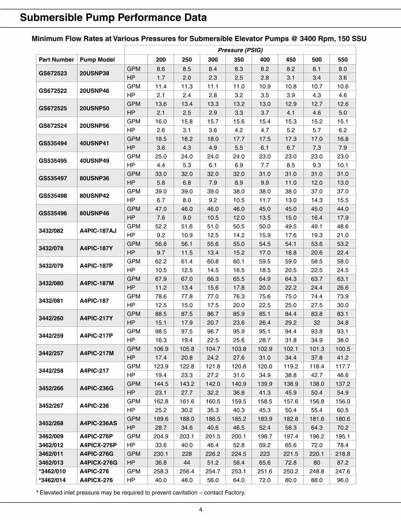
Minimum Flow Rates at Various Pressures for Submersible Elevator Pumps @ 3400 Rpm, 150 SSU
Submersible Pump Performance Data
* Elevated inlet pressure may be required to prevent cavitation – contact Factory.

4 5
Pressure (PSIG)
Part Number Pump Model 600 650 700 750 800 850 900 950 1000
GS672523 20USNP38GPM 7.9 7.8 7.8 7.7 7.7 7.6 7.6 7.5 7.5
HP 3.9 4.2 4.5 4.8 5.0 5.3 5.6 5.9 6.1
GS672522 20USNP46GPM 10.5 10.5 10.4 10.3 10.2 10.2 10.1 10.0 10.0
HP 5.0 5.4 5.7 6.1 6.5 6.8 7.2 7.6 7.9
GS672525 20USNP50GPM 12.5 12.3 12.2 12.1 12.0 11.8 11.7 11.6 11.5
HP 5.4 5.8 6.2 6.8 7.1 7.5 7.9 8.3 8.7
GS672524 20USNP56GPM 15.0 14.9 14.8 14.7 14.6 14.5 14.4 14.3 14.2
HP 6.7 7.2 7.7 8.2 8.7 9.3 9.8 10.3 10.8
GS535494 40USNP41GPM 16.7 16.5 16.3 16.1 16.0 15.8 15.7 15.5 15.4
HP 8.6 9.2 9.8 10.4 11.0 11.6 12.2 12.9 13.5
GS535495 40USNP49GPM 22.0 22.0 22.0 21.0 21.0 21.0 21.0 21.0 21.0
HP 10.9 11.8 12.6 13.4 14.2 15.0 15.8 16.6 17.4
GS535497 80USNP36GPM 31.0 30.0 30.0 30.0 30.0 29.0 29.0 29.0 29.0
HP 14.0 15.1 16.2 17.3 18.3 19.3 20.3 21.4 22.4
GS535498 80USNP42GPM 37.0 36.0 36.0 36.0 36.0 35.0 35.0 35.0 35.0
HP 16.8 18.1 19.3 20.6 21.9 23.2 24.4 25.7 26.9
GS535496 80USNP46GPM 44.0 44.0 43.0 43.0 43.0 43.0 43.0 42.0 42.0
HP 19.4 20.9 22.4 23.8 25.3 26.8 28.3 29.8 31.3
3432/082 A4PIC-187AJGPM 48.2 47.9 47.5 47.1 46.8 46.4 46.1 45.8 45.5
HP 22.6 24.3 26.0 27.7 29.4 31.0 32.7 34.4 36.1
3432/078 A4PIC-187YGPM 52.8 52.4 52.0 51.7 51.3 51.0 50.7 50.3 50.0
HP 24.3 26.1 27.9 29.7 31.5 33.3 35.1 37.0 38.8
3432/079 A4PIC-187PGPM 57.5 57.0 56.6 56.2 55.7 55.3 55.0 54.6 54.2
HP 26.5 28.5 30.5 32.5 34.5 36.5 38.5 40.5 42.5
3432/080 A4PIC-187MGPM 62.6 62.1 61.6 61.1 60.7 60.2 59.8 59.4 58.9
HP 28.8 31.0 33.1 35.3 37.5 39.7 41.9 44.1 46.3
3432/081 A4PIC-187GPM 73.3 72.8 72.3 71.8 71.4 70.9 70.5 70.1 69.7
HP 32.5 35.0 37.5 40.0 42.5 45.0 47.5 50.0 52.5
3442/260 A4PIC-217YGPM 82.5 82 81.4 80.9 80.4 79.9 79.4 78.9 78.4
HP 37.7 40.5 43.3 46.1 48.9 51.7 54.6 57.4 60.2
3442/259 A4PIC-217PGPM 92.5 92.0 91.4 90.9 90.4 89.9 89.4 88.9 88.4
HP 41.2 44.3 47.4 50.5 53.6 56.7 59.8 62.9 66.0
3442/257 A4PIC-217MGPM 99.8 99.1 98.5 97.8 97.2 96.6 96.0 95.5 94.9
HP 44.6 48.1 51.5 54.9 58.3 61.7 65.1 68.5 71.9
3442/258 A4PIC-217GPM 117.0 116.3 115.7 115.1 114.5 113.9 113.4 112.8 112.3
HP 50.5 54.4 58.3 62.1 66.0 69.9 73.8 77.7 81.6
3452/266 A4PIC-236GGPM 136.4 135.6 134.8 134.1 133.4 132.7 132.0 131.4 130.7
HP 59.5 64.0 68.6 73.1 77.6 82.2 86.7 91.3 95.8
3452/267 A4PIC-236GPM 155.3 154.5 153.8 153.2 152.5 151.9 151.3 150.7 150.1
HP 65.5 70.6 75.6 80.7 85.7 90.8 95.8 100.9 105.9
3452/268 A4PIC-236ASGPM 179.6 178.6 177.7 176.8 175.9 175.1 174.3 173.5 172.7
HP 76.1 82.1 88.0 93.9 99.8 105.8 111.7 117.6 123.6
3462/009
3462/012
A4PIC-276P
A4PICX-276P
GPM 194.0 192.9 191.9 190.9 190.0 189.1 188.2 187.3 186.5
HP 84.8 91.2 97.7 104.1 110.5 116.9 123.3 129.7 136.1
3462/011
3462/013
A4PIC-276G
A4PICX-276G
GPM 217.5 216.3 215.1 214 212.9 211.8 210.8 209.8 208.8
HP 94.4 101.7 108.9 116.1 123.3 130.5 137.7 144.9 152.1
*3462/010
*3462/014
A4PIC-276
A4PICX-276
GPM 246.4 245.2 244.1 243.0 242.0 241.0 240.0 239.1 238.1
HP 104.1 112.1 120.1 128.1 136.1 144.1 152.1 160.2 168.2
Minimum Flow Rates at Various Pressures for Submersible Elevator Pumps @ 3400 Rpm, 150 SSU
Submersible Pump Performance Data
* Elevated inlet pressure may be required to prevent cavitation – contact Factory.
6 7
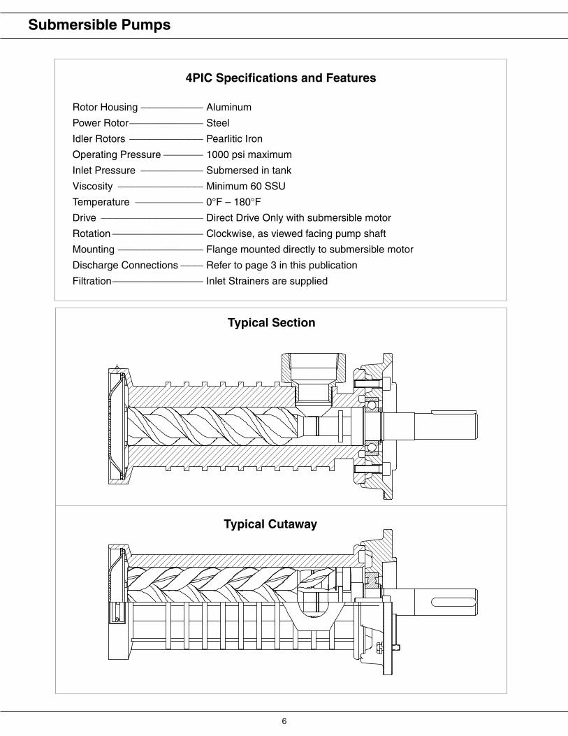
Rotor Housing ___________ Aluminum
Power Rotor_____________ Steel
Idler Rotors _____________ Pearlitic Iron
Operating Pressure _______ 1000 psi maximum
Inlet Pressure ___________ Submersed in tank
Viscosity _______________ Minimum 60 SSU
Temperature ____________ 0°F – 180°F
Drive __________________ Direct Drive Only with submersible motor
Rotation ________________ Clockwise, as viewed facing pump shaft
Mounting _______________ Flange mounted directly to submersible motor
Discharge Connections ____ Refer to page 3 in this publication
Filtration________________ Inlet Strainers are supplied
Typical Cutaway
Typical Section
Submersible Pumps
4PIC Specifications and Features
6 7
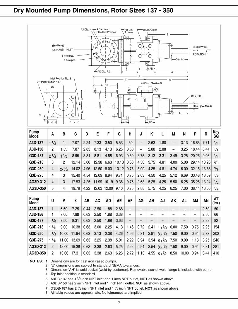
1. Dimensions are for cast iron cased pumps.2. “U” dimensions are subject to standard NEMA tolerances.3. Dimension “AH” is weld socket (weld by customer). Removable socket weld flange is included with pump.4. Top inlet position is standard.
5. A3DB-137 has 1 2 inch NPT inlet and 1 inch NPT outlet, NOT as shown above.6. A3DB-156 has 2 inch NPT inlet and 1 inch NPT outlet, NOT as shown above.
7. G3DB-187 has 2 2 inch NPT inlet and 1 2 inch NPT outlet, NOT as shown above.8. All table values are approximate. No tolerances are implied.
PumpModel A B C D E F G H J K L M N P R Key
SQ
A3D-137 1 2 1 7.07 2.24 7.33 3.50 5.53 .50 – 2.63 1.88 – 3.13 16.65 7.71 3A3D-156 2 1 2 7.87 2.85 8.13 4.13 6.25 0.50 – 2.88 2.88 – 3.25 18.44 8.44 3G3D-187 2 2 1 2 8.95 3.31 8.81 4.88 6.93 0.50 3.75 3.13 3.31 3.49 3.25 20.26 9.06 3G3D-218 3 2 12.14 5.00 12.38 6.63 10.13 0.63 4.50 3.75 4.81 4.00 5.00 29.14 13.26 dG3D-250 4 2-2 14.02 4.96 12.50 8.00 10.12 0.75 5.00 4.25 4.81 4.74 6.00 32.15 13.63 dG3D-275 4 3 15.40 4.54 12.09 8.94 9.71 0.75 2.63 4.50 4.25 5.12 6.69 33.48 13.59 2AG3D-312 4 3 17.53 4.25 11.99 10.19 9.36 0.75 2.63 5.25 4.25 5.50 6.25 35.26 13.24 2AG3D-350 5 4 19.79 4.22 12.03 12.00 9.40 0.75 2.88 5.75 4.25 6.25 7.00 38.44 13.66 2
PumpModel U V X AB AC AD AE AF AG AH AJ AK AL AM AN WT
(lbs.)
A3D-137 1 6.50 7.25 0.44 2.50 1.88 2.88 – – – – – – – 2.50 50A3D-156 1 7.00 7.88 0.63 2.50 1.88 3.38 – – – – – – – 2.50 66G3D-187 1 c 7.50 8.31 0.63 2.50 1.88 3.63 – – – – – – – 2.38 82
G3D-218 1 2 9.00 10.38 0.63 3.00 2.25 4.13 1.46 0.72 2.41 4 x : 6.00 7.50 0.75 2.25 154
G3D-250 1 2 10.00 11.94 0.63 3.13 2.38 4.26 1.96 0.81 2.91 8 x : 7.50 9.00 0.94 2.38 202
G3D-275 1 f 11.00 13.69 0.63 3.25 2.38 5.01 2.22 0.94 3.54 8 x : 7.50 9.00 1.13 3.25 246
AG3D-312 2 12.00 15.38 0.63 3.38 2.63 5.25 2.22 0.94 3.54 8 x : 7.50 9.00 0.94 3.31 281
AG3D-350 2 13.00 17.31 0.63 3.38 2.63 6.26 2.72 1.13 4.55 8 x f 8.50 10.00 0.94 3.44 410
Dry Mounted Pump Dimensions, Rotor Sizes 137 - 350
���������������
�������������
������������
�������
��� ��
�
�
�
��������
��������������
�����������������������������
�
��������
���������������������
�����������
�����������
�������
����������������������������������������
�
�
��
�
������
��
����
��������
�
����������������������
AH Dia.
� ��
������������
NOTES:

8 9
Model: 3D-137Viscosity: 100 SSU
Model: 3D-156Viscosity: 100 SSU
���� ���� ���� ���� ���� ���� ���� ���� �����
��
��
��
��
���
���
�
��
��
��
��
��
��
��
��
��
���
���
���
��������
�������������
�����
����������������
��������
��������
��������
��������
��������
��������
��������
��������
Model: 3D-187������������������
Model: 3D-218Viscosity: 100 SSU
Dry Mounted Hydraulic Elevator Performance Curves

8 9
Model: 3D-250Viscosity: 100 SSU
Model: 3D-275Viscosity: 100 SSU
Model: 3D-312Viscosity: 100 SSU
Model: 3D-350Viscosity: 100 SSU
Dry Mounted Hydraulic Elevator Performance Curves
10 11
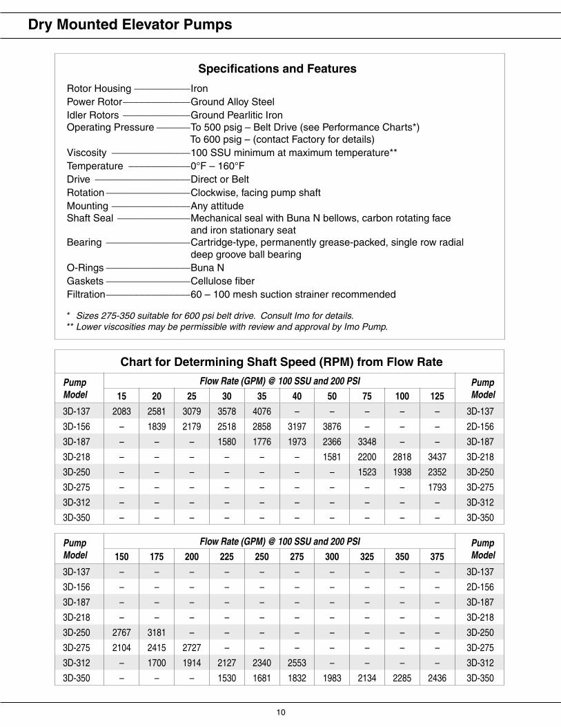
* Sizes 275-350 suitable for 600 psi belt drive. Consult Imo for details.** Lower viscosities may be permissible with review and approval by Imo Pump.
Specifications and Features
Rotor Housing __________IronPower Rotor____________Ground Alloy SteelIdler Rotors ____________Ground Pearlitic IronOperating Pressure ______To 500 psig – Belt Drive (see Performance Charts*) To 600 psig – (contact Factory for details)Viscosity ______________100 SSU minimum at maximum temperature**Temperature ___________0°F – 160°FDrive _________________Direct or BeltRotation _______________Clockwise, facing pump shaftMounting ______________Any attitudeShaft Seal _____________Mechanical seal with Buna N bellows, carbon rotating face and iron stationary seatBearing _______________Cartridge-type, permanently grease-packed, single row radial deep groove ball bearingO-Rings _______________Buna NGaskets _______________Cellulose fiberFiltration_______________60 – 100 mesh suction strainer recommended
Chart for Determining Shaft Speed (RPM) from Flow Rate
PumpModel
Flow Rate (GPM) @ 100 SSU and 200 PSI PumpModel15 20 25 30 35 40 50 75 100 125
3D-137 2083 2581 3079 3578 4076 – – – – – 3D-137
3D-156 – 1839 2179 2518 2858 3197 3876 – – – 2D-156
3D-187 – – – 1580 1776 1973 2366 3348 – – 3D-187
3D-218 – – – – – – 1581 2200 2818 3437 3D-218
3D-250 – – – – – – – 1523 1938 2352 3D-250
3D-275 – – – – – – – – – 1793 3D-275
3D-312 – – – – – – – – – – 3D-312
3D-350 – – – – – – – – – – 3D-350
PumpModel
Flow Rate (GPM) @ 100 SSU and 200 PSI PumpModel150 175 200 225 250 275 300 325 350 375
3D-137 – – – – – – – – – – 3D-137
3D-156 – – – – – – – – – – 2D-156
3D-187 – – – – – – – – – – 3D-187
3D-218 – – – – – – – – – – 3D-218
3D-250 2767 3181 – – – – – – – – 3D-250
3D-275 2104 2415 2727 – – – – – – – 3D-275
3D-312 – 1700 1914 2127 2340 2553 – – – – 3D-312
3D-350 – – – 1530 1681 1832 1983 2134 2285 2436 3D-350
Dry Mounted Elevator Pumps
10 11
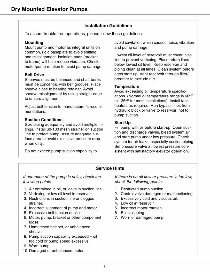
Installation Guidelines
avoid cavitation which causes noise, vibration and pump damage.
Lowest oil level of reservoir must cover inlet-line to prevent vortexing. Place return lines below lowest oil level. Keep reservoir and piping clean at all times. Clean system before each start-up. Vent reservoir through filter/breather to exclude dirt.
TemperatureAvoid exceeding oil temperature specific-ations. (Normal oil temperature range is 60oF to 135oF for most installations). Install tank heaters as required. Run bypass lines from hydraulic block or valve to reservoir, not to pump suction.
Start-UpFill pump with oil before start-up. Open suc-tion and discharge valves, bleed system air and start pump under low pressure. Check system for air leaks, especially suction piping. Set pressure valve at lowest pressure con-sistent with satisfactory elevator operation.
To assure trouble free operations, please follow these guidelines:
MountingMount pump and motor as integral units on common, rigid baseplate to avoid shifting and misalignment. Isolation pads (bracket to frame) will help reduce vibration. Check motor/pump rotation to avoid pump damage.
Belt DriveSheaves must be balanced and shaft bores must be concentric with belt grooves. Place sheave close to bearing retainer. Avoid sheave misalignment by using straight-edge to ensure alignment.
Adjust belt tension to manufacturer’s recom-mendations.
Suction ConditionsSize piping adequately and avoid multiple fit-tings. Install 60-100 mesh strainer on suction line to protect pump. Assure adequate sur-face area to avoid excessive pressure drop when dirty.
Do not exceed pump suction capability to
Service Hints
If operation of the pump is noisy, check the following points:
1. Air entrained in oil, or leaks in suction line. 2. Vortexing or low oil level in reservoir. 3. Restrictions in suction line or clogged
strainer. 4. Incorrect alignment of pump and motor. 5. Excessive belt tension or slip. 6. Motor, pump, bracket or other component
loose. 7. Unmatched belt set, or unbalanced
sheave. 8. Pump suction capability exceeded – oil
too cold or pump speed excessive. 9. Worn pump.10. Damaged or unbalanced motor.
If there is no oil flow or pressure is too low, check the following points:
1. Restricted pump suction.2. Control valve damaged or malfunctioning.3. Excessively cold and viscous oil.4. Low oil in reservoir.5. Incorrect motor rotation.6. Belts slipping.7. Worn or damaged pump.
Dry Mounted Elevator Pumps
12 13
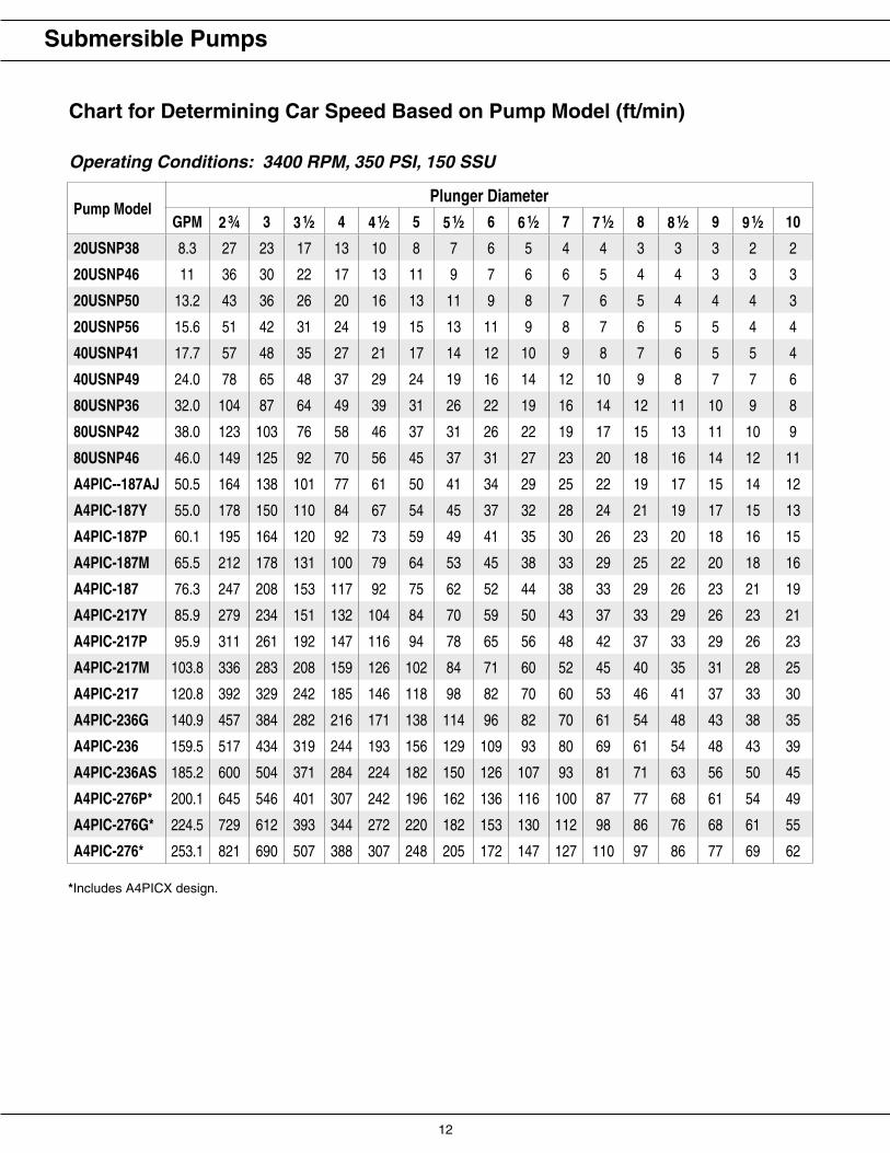
Chart for Determining Car Speed Based on Pump Model (ft/min)
Operating Conditions: 3400 RPM, 350 PSI, 150 SSU
Pump ModelPlunger Diameter
GPM 2 3⁄4 3 3 1⁄2 4 4 1⁄2 5 5 1⁄2 6 6 1⁄2 7 7 1⁄2 8 8 1⁄2 9 9 1⁄2 10
20USNP38 8.3 27 23 17 13 10 8 7 6 5 4 4 3 3 3 2 2
20USNP46 11 36 30 22 17 13 11 9 7 6 6 5 4 4 3 3 3
20USNP50 13.2 43 36 26 20 16 13 11 9 8 7 6 5 4 4 4 3
20USNP56 15.6 51 42 31 24 19 15 13 11 9 8 7 6 5 5 4 4
40USNP41 17.7 57 48 35 27 21 17 14 12 10 9 8 7 6 5 5 4
40USNP49 24.0 78 65 48 37 29 24 19 16 14 12 10 9 8 7 7 6
80USNP36 32.0 104 87 64 49 39 31 26 22 19 16 14 12 11 10 9 8
80USNP42 38.0 123 103 76 58 46 37 31 26 22 19 17 15 13 11 10 9
80USNP46 46.0 149 125 92 70 56 45 37 31 27 23 20 18 16 14 12 11
A4PIC--187AJ 50.5 164 138 101 77 61 50 41 34 29 25 22 19 17 15 14 12
A4PIC-187Y 55.0 178 150 110 84 67 54 45 37 32 28 24 21 19 17 15 13
A4PIC-187P 60.1 195 164 120 92 73 59 49 41 35 30 26 23 20 18 16 15
A4PIC-187M 65.5 212 178 131 100 79 64 53 45 38 33 29 25 22 20 18 16
A4PIC-187 76.3 247 208 153 117 92 75 62 52 44 38 33 29 26 23 21 19
A4PIC-217Y 85.9 279 234 151 132 104 84 70 59 50 43 37 33 29 26 23 21
A4PIC-217P 95.9 311 261 192 147 116 94 78 65 56 48 42 37 33 29 26 23
A4PIC-217M 103.8 336 283 208 159 126 102 84 71 60 52 45 40 35 31 28 25
A4PIC-217 120.8 392 329 242 185 146 118 98 82 70 60 53 46 41 37 33 30
A4PIC-236G 140.9 457 384 282 216 171 138 114 96 82 70 61 54 48 43 38 35
A4PIC-236 159.5 517 434 319 244 193 156 129 109 93 80 69 61 54 48 43 39
A4PIC-236AS 185.2 600 504 371 284 224 182 150 126 107 93 81 71 63 56 50 45
A4PIC-276P* 200.1 645 546 401 307 242 196 162 136 116 100 87 77 68 61 54 49
A4PIC-276G* 224.5 729 612 393 344 272 220 182 153 130 112 98 86 76 68 61 55
A4PIC-276* 253.1 821 690 507 388 307 248 205 172 147 127 110 97 86 77 69 62
Submersible Pumps
*Includes A4PICX design.
12 13
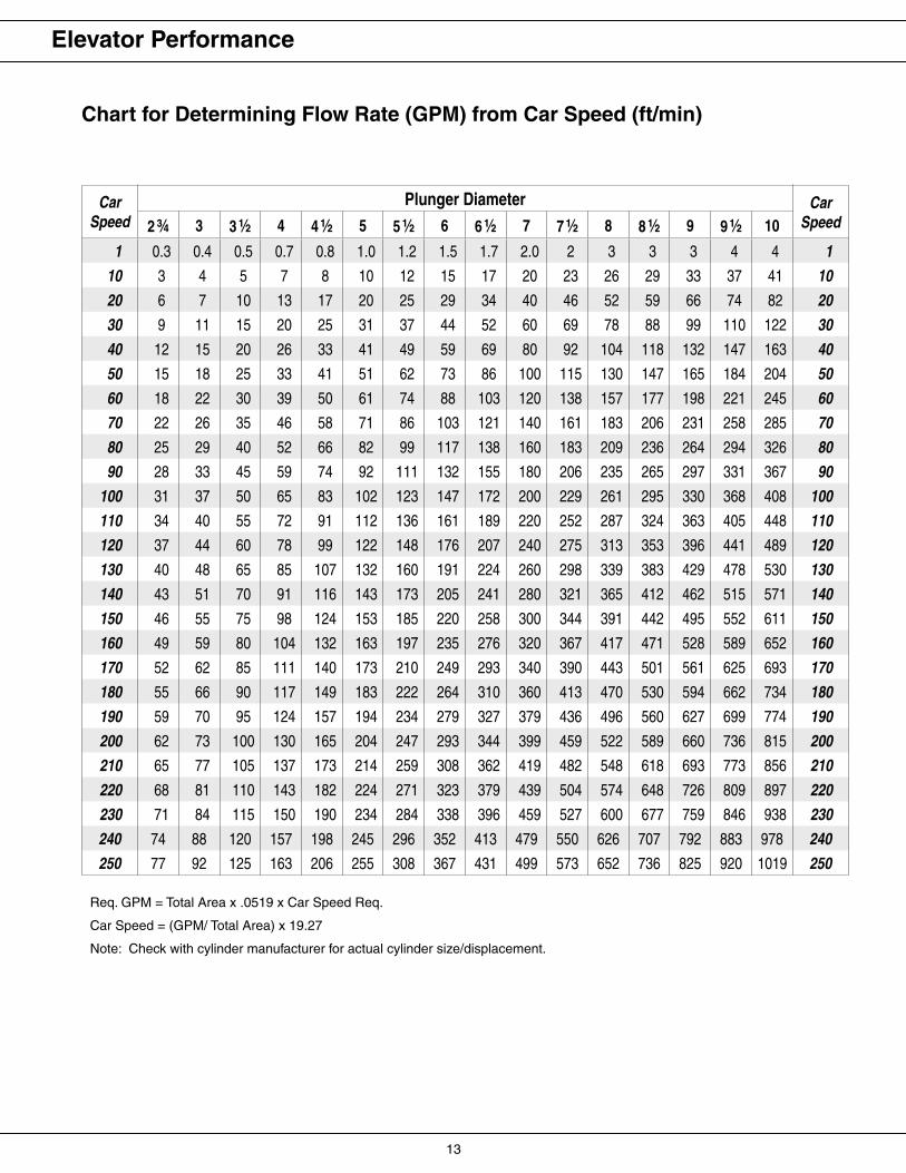
Chart for Determining Flow Rate (GPM) from Car Speed (ft/min)
Req. GPM = Total Area x .0519 x Car Speed Req.
Car Speed = (GPM/ Total Area) x 19.27
Note: Check with cylinder manufacturer for actual cylinder size/displacement.
Elevator Performance
CarSpeed
Plunger Diameter CarSpeed2 3⁄4 3 3 1⁄2 4 4 1⁄2 5 5 1⁄2 6 6 1⁄2 7 7 1⁄2 8 8 1⁄2 9 9 1⁄2 10
1 0.3 0.4 0.5 0.7 0.8 1.0 1.2 1.5 1.7 2.0 2 3 3 3 4 4 1
10 3 4 5 7 8 10 12 15 17 20 23 26 29 33 37 41 10
20 6 7 10 13 17 20 25 29 34 40 46 52 59 66 74 82 20
30 9 11 15 20 25 31 37 44 52 60 69 78 88 99 110 122 30
40 12 15 20 26 33 41 49 59 69 80 92 104 118 132 147 163 40
50 15 18 25 33 41 51 62 73 86 100 115 130 147 165 184 204 50
60 18 22 30 39 50 61 74 88 103 120 138 157 177 198 221 245 60
70 22 26 35 46 58 71 86 103 121 140 161 183 206 231 258 285 70
80 25 29 40 52 66 82 99 117 138 160 183 209 236 264 294 326 80
90 28 33 45 59 74 92 111 132 155 180 206 235 265 297 331 367 90
100 31 37 50 65 83 102 123 147 172 200 229 261 295 330 368 408 100
110 34 40 55 72 91 112 136 161 189 220 252 287 324 363 405 448 110
120 37 44 60 78 99 122 148 176 207 240 275 313 353 396 441 489 120
130 40 48 65 85 107 132 160 191 224 260 298 339 383 429 478 530 130
140 43 51 70 91 116 143 173 205 241 280 321 365 412 462 515 571 140
150 46 55 75 98 124 153 185 220 258 300 344 391 442 495 552 611 150
160 49 59 80 104 132 163 197 235 276 320 367 417 471 528 589 652 160
170 52 62 85 111 140 173 210 249 293 340 390 443 501 561 625 693 170
180 55 66 90 117 149 183 222 264 310 360 413 470 530 594 662 734 180
190 59 70 95 124 157 194 234 279 327 379 436 496 560 627 699 774 190
200 62 73 100 130 165 204 247 293 344 399 459 522 589 660 736 815 200
210 65 77 105 137 173 214 259 308 362 419 482 548 618 693 773 856 210
220 68 81 110 143 182 224 271 323 379 439 504 574 648 726 809 897 220
230 71 84 115 150 190 234 284 338 396 459 527 600 677 759 846 938 230
240 74 88 120 157 198 245 296 352 413 479 550 626 707 792 883 978 240
250 77 92 125 163 206 255 308 367 431 499 573 652 736 825 920 1019 250
14 15
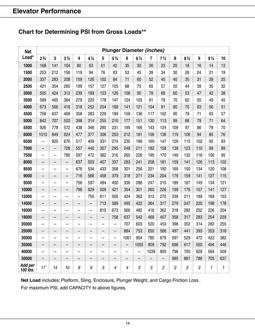
NetLoad*
Plunger Diameter (inches)
2 3⁄4 3 3 1⁄2 4 4 1⁄2 5 5 1⁄2 6 6 1⁄2 7 7 1⁄2 8 8 1⁄2 9 9 1⁄2 10
1000 168 141 104 80 63 51 42 35 30 26 23 20 18 16 14 13
1500 253 212 156 119 94 76 63 53 45 39 34 30 26 24 21 19
2000 337 283 208 159 126 102 84 71 60 52 45 40 35 31 28 25
2500 421 354 260 199 157 127 105 88 75 65 57 50 44 39 35 32
3000 505 424 312 239 189 153 126 106 90 78 68 60 53 47 42 38
3500 589 495 364 279 220 178 147 124 105 91 79 70 62 55 49 45
4000 673 566 416 318 252 204 168 141 121 104 91 80 70 63 56 51
4500 758 637 468 358 283 229 189 159 136 117 102 90 79 71 63 57
5000 842 707 520 398 314 255 210 177 151 130 113 99 88 79 71 64
5500 926 778 572 438 346 280 231 195 166 143 124 109 97 86 78 70
6000 1010 849 624 477 377 306 253 212 181 156 136 119 106 94 85 76
6500 – 920 676 517 409 331 274 230 196 169 147 129 115 102 92 83
7000 – – 728 557 440 357 295 248 211 182 158 139 123 110 99 89
7500 – – 780 597 472 382 316 265 226 195 170 149 132 118 106 95
8000 – – – 637 503 407 337 283 241 208 181 159 141 126 113 102
8500 – – – 676 534 433 358 301 256 221 192 169 150 134 120 108
9000 – – – 716 566 458 379 318 271 234 204 179 159 141 127 115
9500 – – – 756 597 484 400 336 286 247 215 189 167 149 134 121
10000 – – – 796 629 509 421 354 301 260 226 199 176 157 141 127
12000 – – – – 755 611 505 424 362 312 272 239 211 189 169 153
14000 – – – – – 713 589 495 422 364 317 279 247 220 198 178
16000 – – – – – 815 673 566 482 416 362 318 282 252 226 204
18000 – – – – – – 758 637 542 468 407 358 317 283 254 229
20000 – – – – – – – 707 603 520 453 398 352 314 282 255
25000 – – – – – – – 884 753 650 566 497 441 393 353 318
30000 – – – – – – – 1061 904 780 679 597 529 472 423 382
35000 – – – – – – – – 1055 909 792 696 617 550 494 446
40000 – – – – – – – – – 1039 905 796 705 629 564 509
50000 – – – – – – – – – – – 995 881 786 705 637
Add per 100 lbs. 17 14 10 8 6 5 4 4 3 3 2 2 2 2 1 1
Chart for Determining PSI from Gross Loads**
Net Load includes: Platform, Sling, Enclosure, Plunger Weight, and Cargo Friction Loss.
For maximum PSI, add CAPACITY to above figures.
Elevator Performance

14 15
Elevator Reference Information
Effect of Flow Rate on Plunger Speed���������������������
���
���
���
���
���
�
���������������������������������
�
���
�
���
�
���
����
���
�
���
�������������������������� ��� �������


