Page 1
January 08, 2018
Table of Contents
Chapter One -- Right-Of-Way Preparation
Preliminary Investigation…………………………………………………..… 1-1
Stormwater Management…………………………………………………….. 1-5
Clearing and Grubbing………………………………………………..…..….. 1-5
Removal of Structures and Obstructions……………………………….......... 1-6
Building and Foundation Removal
Inspection and Removal of Asbestos
Bridge Removal
Pipe and Sewer Removal
Pavement and Miscellaneous Removal
Chapter Two -- Soils Identification and Classification
Materials……………………………………………………….…..……….. 2-1
Origin and Geology of Soils
Soil Profiles
Soil Composition and Texture
Soil Classification
Field Identification and Classification of Soils
Rock and Shale Embankment………………………………….…..……….. 2-13
Principal Rock Types
Indiana Geology
Rock
Shale, Shale and Soft Rock Mixtures, or Soft Rock
Other Embankment and Fill Materials…………………………………..…… 2-15
Borrow
B Borrow
Structural Backfill
Rock Backfill
Aggregate Materials……………………………………………..………….. 2-15
Aggregate Bases
Subbase
Aggregate Pavement or Shoulders
Synthetic Materials………………………………………..………………… 2-15
Coal Combustion By-Products
Crushed Glass
Recycled Concrete Pavement
Recycled Foundry Sand
Chapter Three -- Excavation
Common Excavation……………………………………………………..…… 3-1
Page 2
January 08, 2018
Submitting Samples
Preparing the IT 530
Rock Excavation…………………………………………………..................... 3-3
Exploratory drilling
Rock Pre-Splitting
Explosives
Primary Blasting
Restrictions
Finished Grade
Unclassified Excavation……………………………………………………... 3-5
Waterway Excavation
Class Y Excavation
Class X Excavation
Wet Excavation
Dry Excavation
Foundation Excavation, Unclassified
Disposal of Excavated Material…………………………………………..…... 3-6
Suitable Material
Unsuitable Material
Excess Material
Borrow…………………………………………………………………..…….. 3-7
Contractor Responsibilities……………………………………………..…….. 3-8
Preparing a Borrow Pit………………………………………………….……. 3-8
Peat Excavation…………………………………………………………..…… 3-9
Treatment of Existing Fills
Treatment by Removal
Treatment by Displacement
Peat Disposal
Chapter Four -- Excavation Construction Requirements
General Preparation………………………………………………………..… 4-1
General Requirements………………………………………………….……. 4-3
Temporary Erosion Control………………………………………………..… 4-3
Lifts…………………………………………………………………….……. 4-4
Equipment………………………………..……………………………….…. 4-4
Hauling
Spreading
Compacting
Chapter Five -- Embankment Construction
Rock Embankment……………………………………………….…………… 5-1
Lift Requirements
Compaction Methods
Shale and Soft Rock Embankments………………………………………...... 5-2
Lift and Compaction Requirements
Page 3
January 08, 2018
Embankments on Hillsides and Slopes……………………………………..... 5-3
Embankment over Existing Roads………………………………………..….. 5-3
Treatment of Existing Roadbeds…………………………………………….. 5-4
Compaction Control……………………………………………………….… 5-5
Settlement Control…………………………………………………………... 5-6
Chapter Six -- Measurement and Earthwork Calculations
Contract Quantity Payment…………………………………………………. 6-1
Measured Quantity Payment………………………………………………… 6-2
Measurement and Earthwork Calculations……………………………….…. 6-2
Cross Sections…………………………………………………………….… 6-2
Volumes…………………………………………………………………….. 6-3
Chapter Seven -- Subgrade Construction
Construction Requirements………………………………………….............. 7-2
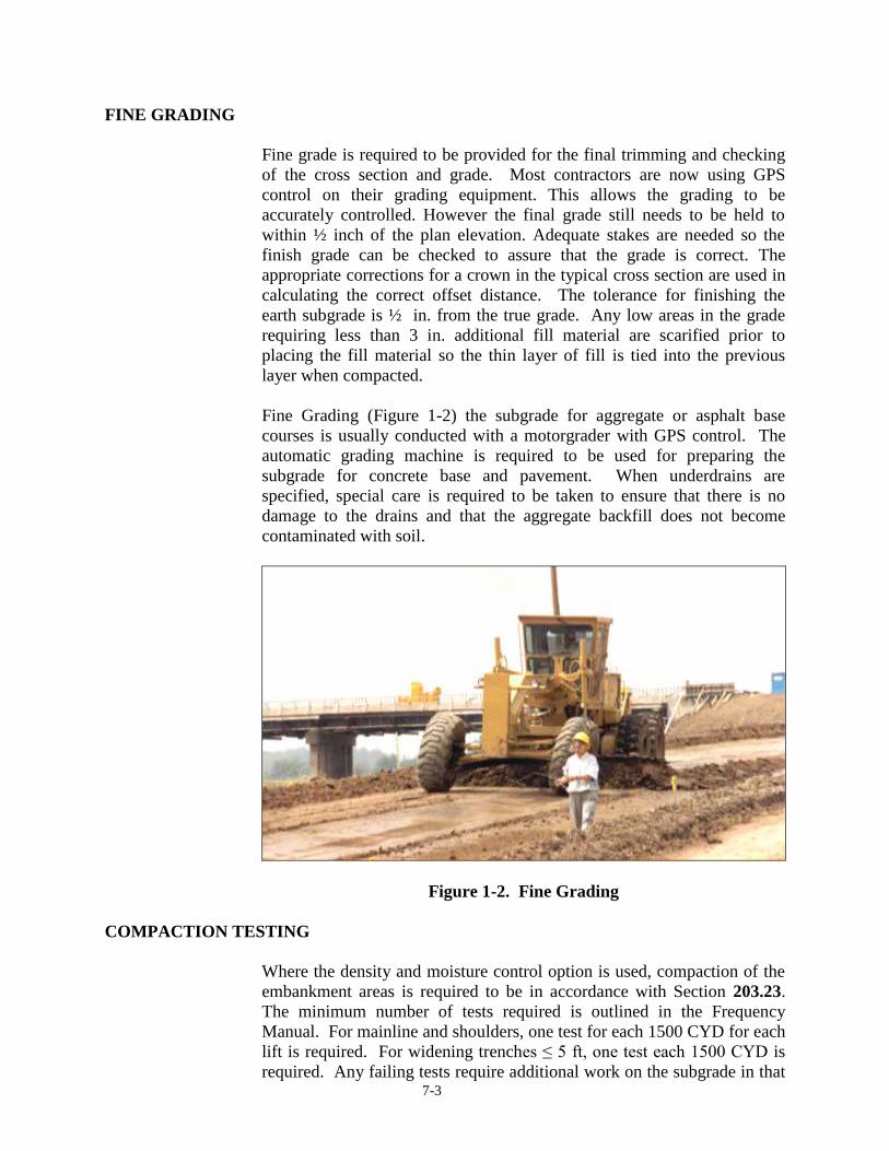
Fine Grading……………………………………………………………........ 7-2
Density Testing……………………………………………………………… 7-3
Proofrolling…………………………………………………………………. 7-4
Subgrade Treatments……………………………………………………….. 7-4
Chemical Modification of Soils…………………………………………….. 7-5
Moisture Control……………………………………………………………. 7-6
Drainage…………………………………………………………………….. 7-7
Measurement and Payment…………………………………………………. 7-7
Summary……………………………………………………………………. 7-7
Chapter Eight -- Finishing
Shoulders…………………………………………………………………… 8-1
Ditches……………………………………………………………………… 8-1
Slopes……………………………………………………………………….. 8-1
Earth Graded Roads………………………………………………………… 8-2
Final Trimming and Cleaning………………………………………………. 8-2
Measurement and Payment…………………………………………………. 8-3
Chapter Nine -- Special Fill and Backfill
B Borrow Fill and Backfill………………………………………………….. 9-1
Materials
Flowable Mortar Substitution
Construction Requirements
Mechanical Compaction
Embankment for Bridges
B Borrow Around Bents
Aggregate for End Bent Backfill
Unbalanced Backfill
Page 4
January 08, 2018
Spandrel Filling
Method of Measurement
Basis of Payment
Flowable Backfill………………………………………………………..…… 9-5
Proportioning
Flow
Average Penetration Resistance
Mixing Equipment
Placement
Limitation of Operations
Method of Measurement
Basis of Payment
Chapter Ten – Mechanically Stabilized Earth Retaining Walls
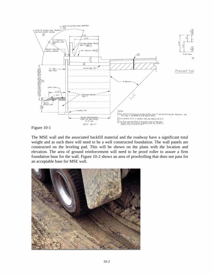
Design ………………………………………………………………………. 10-1
MSE Wall Shop Drawings
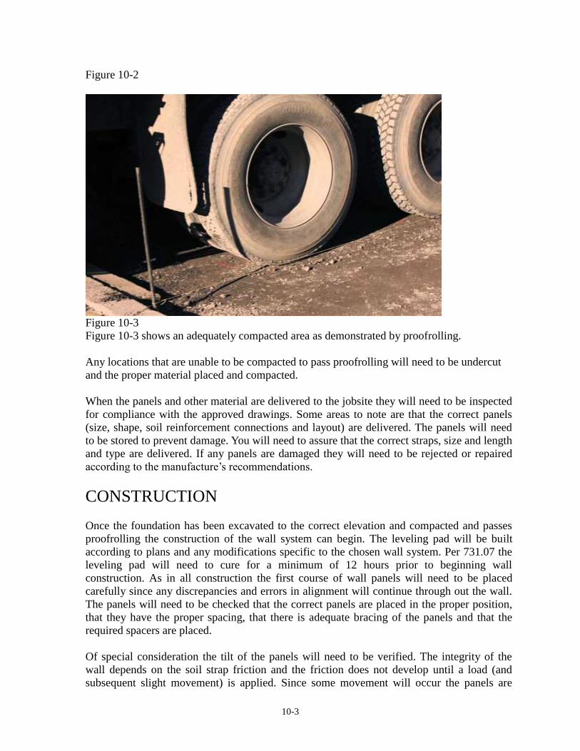
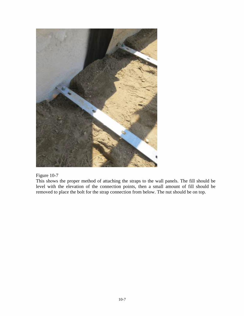
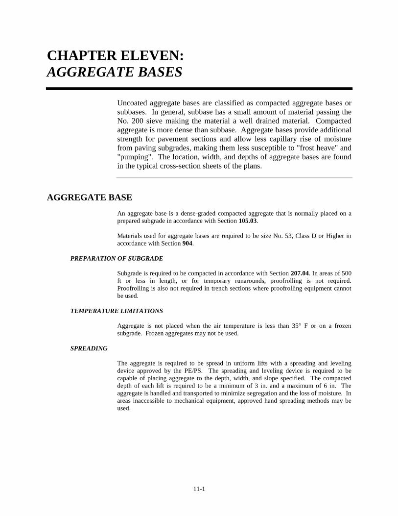
Construction
Chapter Eleven -- Aggregate Bases
Aggregate Base……………………………………………………………… 11-1
Preparation of Subgrade
Temperature Limitations
Spreading
Compacting
Checking and Correcting Base
Priming
Method of Measurement
Basis of Payment
Subbase……………………………………………………………………… 11-2
Preparation of subgrade
Temperature Limitations
Spreading
Compacting
Checking and Correcting Base and Surface
Method of Measurement
Basis of Payment
Aggregate Pavements or Shoulders……………………………………..…… 11-4
Preparation of Subgrade
Temperature Limitations
Spreading
Compacting
Checking and Correcting Base
Dust Palative
Method of Measurement
Basis of Payment
Page 5
January 08, 2018
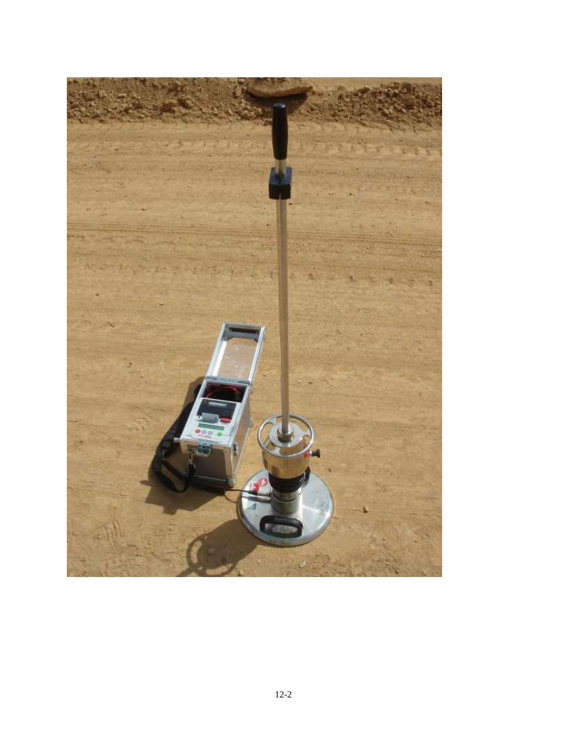
Chapter Twelve – Light Weight Deflectometer
Overview……………………………………………………….…………… 12-1
Using the Light Weight Deflectometer……………………………….……… 12-2
Chapter Thirteen – Dynamic Cone Penetrometer
Overview……………………………………………………………….……. 13-1
Components………………………………………………………………….. 13-2
Use of the DCP……………………………………………………………… 13-4
Chapter Fourteen -- Family of Curves and One-Point Proctor Procedures
Maximum Dry Density……………………………………………………… 14-1
Family of Curves………………………………………….………………… 14-1
One-Point Proctor…………………………………………………………… 14-2
Example Problem…………………………………………………………… 14-2
Page 6
1 Right-of-Way Preparation
Preliminary Investigation Storm Water Management
Clearing and Grubbing
Removal of Structures and Obstructions Building and Foundation Removal
Inspection and Removal of Asbestos
Bridge Removal
Pipe and Sewer Removal
Pavement and Miscellaneous Removal
Page 7
1-1
CHAPTER ONE:
RIGHT-OF-WAY PREPARATION
Whether the work requires widening of an existing pavement section or
the construction of a new roadway section through a new undisturbed right
of way, certain preliminary investigations are required. The PE/PS obtains
right of way grants for all parcels of property purchased for the new work.
These also include grants for temporary right of ways. From the
construction plans, all right of way is staked so that the limits of
ownership are clearly visible and areas of temporary ownership for
construction are known. All INDOT employees and the Contractor are
required to be aware of the limits so that no disputes arise over work
activities outside our property or destroying or disturbing private property.
Any work on the right of way has some involvement with public or private
utilities.
PRELIMINARY INVESTIGATION
During the completion of the plans, INDOT has already notified all public
utilities and all pipe line owners or other parties affected so that they may
plan to move and relocate their existing facilities. Delays caused to the
Contractor by public utility companies are reason for time extension and
may cause contracts to be extended into another construction season.
Existing survey section corners and other survey controlled points and
bench marks are required to be referenced for establishment when the
contract is completed. The County Surveyor is contacted to obtain the
proper location of all section survey references.
Another area of importance is the investigation of existing underground
drainage. Farm field tiles placed by farmers are required to be outletted or
continued across the project limits so the drainage is uninterrupted. Legal
county tiles and ditches are required to be maintained and preserved. The
PE/PS coordinates with the County Surveyor or County Engineer to assure
that all legal county drainage has been located.
If the Contractor is required to assist in the investigation of underground
drainage by excavation, this excavation is paid for as set out in Section
203.
STORM WATER MANAGEMENT
The specifications require the contractor to schedule and conduct its
operations to minimize erosion of soils and to prevent sediment from
reaching streams, irrigation systems, lakes, reservoirs, etc. The discussion
Page 8
1-2
of storm water management must be included in all pre-construction
conferences. The requirements to schedule seeding and sodding operations
as the construction progresses, instead of waiting until the final stages of
the project, should be stressed when discussing these operations with the
contractor. Indiana Administrative Code Title 327 IAC 15-5 (Rule 5),
defines the State’s regulations governing storm water management for
land disturbing activities effecting one or more acres. These regulations
are the responsibility of IDEM to enforce. Regulation compliance is the
responsibility of the contractor and INDOT.
The PE/S should have a thorough understanding of good storm water
management, and the best management practices (BMP) utilized by the
Department. The PE/S should also understand the processes by which the
Department obtains approval from IDEM to perform construction projects
under Rule 5 and the requirements placed on the contractor for storm
water management by the contract documents. The Department’s storm
water BMPs are defined within the Standard Specifications, the Standard
Drawings, the contract plans, and the Department's Storm Water
Management Field Guide. The PE/S should review this information to
understand the purpose and scope of erosion and sediment control
established for the contract. Also, the IDEM Storm Water Quality Manual
provides excellent reference information for review by the PE/S to ensure
the project is in compliance with Rule 5. It is strongly advised that the
PE/S retain a copy of Rule 5 for review and reference.
Purpose
The purpose of storm water management is to minimize or eliminate the
potential for soil erosion and off-site sedimentation. At its core, storm
water management has two basic processes. The first core process is
erosion control. Erosion control measures are designed to maintain the soil
on the ground, to keep the soil within the construction area, and to
minimize its movement. Erosion control measures are more cost effective
than trying to manage sediment after it has begun to move. Minimizing
water or wind produced movement of soils from stockpiles, new
embankments or ditch lines would fall within the erosion control category.
The second core process is sediment control. Sediment control measures
are designed to slow the movement of water to allow time for sediment
particles carried by the water to settle and drop out of suspension.
Sediment control measures are generally more expensive, require more
maintenance, and are a less effective storm water management tool. The
management of soil particles moving with storm water during a rain event
would fall within the sediment control category.
Storm Water Pollution Prevention Plan
The Department's Environmental Services Section (ES) works with the
designer and IDEM to obtain approval to publish the Notice of Intent
(NOI) prior to letting a contract that will disturb one or more acres of land.
INDOT’s designer develops an initial Storm Water Pollution Prevention
Page 9
1-3
Plan (SWPPP) to address anticipated land disturbing activities within the
construction limits during the contract. Prior to contract letting, the plan is
reviewed by ES, and occasionally by IDEM. Revisions are made as
necessary to provide a workable plan that ultimately becomes part of the
contract documents.
Contractor’s Storm Water Quality Control Plan
Plans are incorporated into the contract to address the anticipated needs
for storm water management during the different phases of the
construction contract. However, since INDOT’s designer, ES, and IDEM
cannot foresee the exact methods and sequence of operations the
contractor may use on a given project, the Specifications require the
contractor to develop and submit for acceptance a Storm Water Quality
Control Plan (SWQCP) to the PE/S describing the sequencing,
prosecution, and phasing of the work for each stage of the construction
contract. The SWQCP shall be prepared and stamped by a licensed
engineer that holds a current certification for a Certified Professional in
Erosion and Sediment Control (CPESC), CPESC-In Training, or an
approved equal. INDOT’s design developed SWPPP and the Contractor’s
developed SWQCP shall work in coordination with each other to complete
the requirements of Rule 5. The SWQCP, or any phase of the SWQCP,
shall be submitted 14 days prior to the start of any earth disturbing
activities for that particular phase. The SWQCP must address:
(a) Locations of all proposed soil stockpiles.
(b) Locations of all proposed equipment storage areas, fueling
locations, construction trailers, batch plants, and designated
concrete truck washouts. The SWQCP must also include a written
plan for the collection, storage, and disposal of concrete washout
waste water. The capacity of the washout containers must be
adequate to accommodate the size of the concrete pour. A
secondary container shall also be kept on site. The container or pit
shall be lined with a continuous sheet of plastic that is a minimum
10 mil thick. The material must be leak free and cannot be
overlapped. Soils that are contaminated by spills shall be excavated
and disposed of in accordance with 202.08. All costs for work shall
be the responsibility of the Contractor.
(c) Proposed construction sequence and phasing of the erosion
control measures.
(d) Locations of all construction entrances where vehicles and
equipment will enter and exit the site.
(e) Material handling and spill prevention plan, which includes a
listing of expected materials that may be present on the site during
construction and the written plan of how those materials will be
handled to minimize their potential for entering the storm water
runoff from the site.
Page 10
1-4
(f) Statements that the Storm Water Management features used
shall, at a minimum, be inspected on a weekly basis and within 24
hours of every ½ inch rain event.
(g) Monitoring and maintenance plan for erosion and sediment
control measures.
Additional contractor responsibilities within the SWQCP process include:
(a) Designating a trained employee as the Storm Water Quality
Manager (SWQM) to oversee and be in responsible charge of the
contractor’s storm water management operations.
(b) Ensuring that the signed and dated SWQCP is submitted 14
days prior to any earth disturbing activities.
(c) Following their accepted SWQCP.
(d) Completing inspections of all installed BMPs at the correct
frequency and documenting the inspections on the Storm Water,
Erosion and Sediment Control Inspection Report.
(e) Amending and resubmitting their SWQCP as necessary to
address changes during the construction of the project.
The Storm Water Quality Control Plan is a “living” document and is
required to be amended by the contractor as new situations occur or as the
plan of operation changes. Once the SWQCP is received from the
contractor, the PE/S will perform the following:
(a) Review the SWQCP within 14 days of receipt utilizing the
process outlined in ITM 803, Section 15 and the SWQCP checklist
within Appendix I.
(b) Contact their Area Engineer for clarification and utilize the ES
Permit Coordinator as an information reference for the SWQCP
review.
(c) Sign and date the SWQCP to document the review of the
methodology and approval of the content.
In addition to the work covered by the contract documents and the
SWQCP, the contractor may also need to operate offsite borrow and
disposal sites. Environmental permits for these sites are solely the
responsibility of the contractor and are not covered in any part by the
Department’s SWPPP, the plans, or the contract permits. A copy of the
Contractor’s offsite operations NOI for items such as offsite stockpiles,
borrow sites, waste sites, or storage areas shall be submitted to the PE/PS
prior to operations at those sites.
3.1.4 Installation, Inspection, and Maintenance
As defined within the Standard Specifications, the contractor is
responsible for the proper installation, inspection and maintenance of all
storm water management measures. In accordance with Rule 5, storm
water management inspections are required to occur at a minimum
frequency of once every 7 days, and by the end of the next business day
following each measurable storm event equal to or greater than 1/2 inch of
rainfall. Inspection findings, both good and bad, shall be documented and
recorded on the Storm Water, Erosion and Sediment Control Inspection
Report. The report can be accessed from the Department’s Environmental
Page 11
1-5
Services Storm Water website. The PE/S is responsible to make sure that
the contractor’s SWQM has submitted inspection reports correctly, in a
timely manner, and in accordance with Rule 5 requirements. Any
additional storm water management features suggested by the contractor’s
SWQM in the Storm Water, Erosion and Sediment Control Inspection
Report should be evaluated and either accepted or denied by the PE/S on
the inspection report. Evaluations of any proposed new storm water
management features should include discussions with the AE, and the ES
Permit coordinator. They can help determine and ensure that the contract
continues to meet the intent of the specifications, maintains economic
value, and maintains compliance with all requirements of Rule 5. As with
any plan, it is not uncommon for changes to be made in order for the plan
to work properly. Similarly, the storm water management measures in the
contract must be used to their best advantage to accomplish the job.
Therefore, some storm water management item quantities may overrun
and some may underrun. The PE/S must use their best judgment and work
with the contractor, AE, and the ES Permit Coordinator to adapt the best
plan to fit the actual conditions of each project while still being as efficient
as possible with the use of BMPs. All of the initiated changes should be
documented as amendments to the SWQCP. The references and
Department websites discussed within this section can be found in the
Department’s Storm Water Management Field Guide.
CLEARING AND GRUBBING
When the Contractor arrives at the job-site, one of the first orders of
business is to clear the right-of-way in preparation for construction. This
work consists of the removal and disposal of all vegetation and debris
within the limits of construction which is in the way of the construction
work. Any items within the right-of-way that are designated to remain in
place are not to be disturbed or damaged by the Contractor.
Trees that are encountered within the construction limits may be removed.
If the tree stump is cut off level with the ground and is a minimum of 3 ft
below the final subgrade, the stump may be left in place. If trees are
completely removed, the roots from the stump are required to be grubbed
from the ground around the old stump. Any holes created in the
embankment area are required to be backfilled satisfactorily up to the level
of the existing ground prior to starting the new embankment. Burning
perishable items may only be done if local laws, ordinances, and the
contract permit burning.
The measurement and payment of clearing of right of way is a somewhat
complicated process. Payment may be by the acre, by a lump sum, by
length, or by individual units. If tree removal is paid for by an individual
unit, the tree is measured at a height of 24 in. above the ground. Any tree
less than 4 in. in diameter is classified as brush and no payment is made.
Page 12
1-6
BORROW AND DISPOSAL SITES
The contractor must submit proposed borrow and disposal site locations to
the PE/S for approval. Form IC 203, Request for Approval of Borrow or
Disposal Site, is available on the Department’s website and must be
completed by the contractor for each proposed site and submitted to the
PE/S for approval. The form requires the contractor’s signature certifying
that they have complied with all environmental laws and regulations
required to perform the planned operations at the site. The PE/S will
review the form and sign it if properly completed. A site must be approved
before the contractor can begin operations at the site. Requirements for
different types of sites can be found in 203.08. The primary reason for the
need to review and approve borrow and disposal sites is to help prevent
contractors from inadvertently dumping in a wetlands area or disturbing an
archeologically sensitive site. As the owner of the project, INDOT is
responsible to take measures to prevent these occurrences. The
specifications are intended to give the PE/S the tools necessary to
reasonably ensure that the contractor has taken appropriate measures to
prevent borrow or disposal operations from becoming a violation of
environmental laws. The PE/S must use their best judgment to reasonably
determine when a given area may or may not require all environmental
work to be done. By contract, the Department’s approval of borrow or
disposal sites does not relieve the contractor of any obligations or
penalties under the law. The Department will hold the contractor
responsible, not the PE/S, if an approved site turns out to be in non-
compliance with any law or regulation. It is not the intent of the
Department’s procedures to place the PE/S in a position of responsibility
for the contractor’s compliance with the laws, only to provide a means for
the PE/S and the Department to be aware of the contractor’s planned sites
and to obtain the contractor’s certification that they are in compliance with
the laws. If the PE/S has questions about a given site, they should contact
the AE for further guidance.
REMOVAL OF STRUCTURES AND OBSTRUCTIONS
Most contracts require removal of structures and obstructions. This
includes the removal and disposal of buildings, fences, structures, old
pavement, abandoned pipe lines, and any other obstructions that are not
designated in the contract to remain in place.
BUILDING AND FOUNDATION REMOVAL
A Contractor is not allowed to begin removing a building without written
authority from INDOT. For buildings or houses that are required to be
removed, the Contractor removes the buildings and the foundations or
basement walls to an elevation 1 ft below original ground. All debris and
trash that is accumulated in a basement or foundation is removed. Any
floor drains encountered are plugged, and any basement floors are broken.
All public utilities into the building are to be shut off prior to beginning of
demolition. The Contractor is responsible for notifying the utility
Page 13
1-7
companies involved. Basements are backfilled with B Borrow in
accordance with Section 203.
Wells, cisterns, septic tanks, and other tanks are cleaned and backfilled in
an approved manner. Cisterns, septic tanks, and other tanks that cannot be
satisfactorily backfilled are removed. All abandoned wells are sealed and
backfilled in accordance with Indiana code.
INSPECTION AND REMOVAL OF ASBESTOS
The contract documents will contain information on if the building
contains asbestos. All State, Federal and Local regulations are required to
be followed in cleaning up the hazardous materials.
BRIDGE REMOVAL
Clearing of the right-of-way may include the removal of bridges, culverts,
and other drainage structures. Bridge foundations are removed to the
existing stream bed, and those portions outside the stream bed are
removed 1 ft below the original ground. The removal of a reinforced
concrete arch includes the removal of all of the pavement and backfill of
the arch.
Blasting should only be used in the demolition of bridges if allowed by
Local ordinances. When a portion of a bridge structure is removed to
widen an existing structure, care is taken not to damage the portion of the
existing structure to remain in place. If specified, broken up concrete from
bridge removal may be used as riprap on the contract.
PIPE AND SEWER REMOVAL
Materials not specified to be salvaged become the property of the
Contractor. Sanitary and storm sewers no longer in use are removed from
under the roadway and shoulders.
PAVEMENT AND MISCELLANEOUS REMOVAL
When the removal includes concrete pavement, sidewalks, curbs, and
other miscellaneous concrete items, this concrete may be broken into
pieces and used as riprap on the contract or disposed of off the right-of-
way. Pavement removal includes the concrete pavement and all HMA
overlay courses on existing public roads, streets, and alley pavements.
Parking lots and driveways are not considered pavement removal. When a
portion of pavement is removed, the limits of removal are marked and
sawed along these limits to assure a smooth line of removal. Any portion
that is damaged outside the removal lines is replaced at the Contractor’s
expense. Sawing of pavement to be removed is not paid for directly, but is
included in the cost of pavement removal.
Page 14
2-8
2 Materials
Materials
Soil Composition and Texture
Soil Classification
Field Identification and Classification of Soils
Rock and Shale Embankment Principal Rock Types
Indiana Geology
Rock
Shale, Shale and Soft Rock Mixtures, or Soft Rock
Other Embankment and Fill Materials Borrow
B Borrow
Structural Backfill
Rock Backfill
Aggregate Materials Aggregate Base
Subbase
Aggregate Pavements or Shoulders
Synthetic Materials Coal Combustion By-Products
Crushed Glass
Recycled Concrete Pavement
Recycled Foundry Sand
Page 15
2-1
CHAPTER TWO:
MATERIALS
All materials used in the construction of highway embankments, fills,
subgrades, and subbases originate from the Earth. Most of these materials
are natural in origin, i.e. they are the result of geologic processes that
occur naturally as opposed to synthetic materials which are the result of
industrial processes (i.e. slag, flyash). This chapter focuses on the natural
earth materials.
Earth materials consist of two types: soil and rock. AASHTO M 146
defines soil as, “sediments or other unconsolidated accumulations of solid
particles produced by the physical and chemical disintegration of rocks,
and which may or may not contain organic matter.” Soil may also be
defined as all unconsolidated materials overlying bedrock. The key word
in these definitions is "unconsolidated". Soil is essentially natural material
that is not indurated (hardened, cemented) into a cohesive mass. Soil
exists in a loose, unbound condition and therefore may be easily excavated
with construction equipment.
AASHTO M 146 defines rock as, “natural solid mineral matter occurring
in large masses or fragments.” Rock may be composed of hardened or
cemented soil. The process of converting soil into rock is called
lithification. Since lithification takes time and may be incomplete, the
distinction between rock and soil may be unclear. For example, soil
hardpans have been indurated by chemical action and may be quite hard,
but are not considered to be rock. Shale is another example. Shale is
considered to be rock by Geologists and soil by Engineers.
Soil and rock may be processed into aggregates by excavating, blasting,
dredging, crushing, washing, and screening. These aggregates are
considered natural aggregates since the chemical and mineralogical
composition of the individual fragments or grains has not been altered.
Natural aggregates are used extensively as materials for highway
construction and are discussed in this chapter as well.
The following references are required to be reviewed in detail:
INDOT Standard Specifications
1) Section 101
2) Sections 203.03, 203.08 and 203.20
Page 16
2-2
3) Section 211.02
4) Sections 301.02, 302.02 and 303.02
5) Section 903
6) Section 904
SOIL COMPOSITION AND TEXTURE
Soil is made up of the following components:
1) Boulders
2) Gravel
3) Sand
4) Silt
5) Clay
6) Colloids
7) Organic material
With the exception of organic material, the components listed denote grain
size and not origin or chemical/mineralogical composition. Organic
materials are largely decayed plant matter and may be found in any state
of decay.
Soil texture refers to the size and distribution of the components that
comprise the soil. This is commonly referred to as the gradation of the
soil.
SOIL CLASSIFICATION
Section 903 and AASHTO M 145 detail the classification system INDOT
uses for all soils. Section 903 is strictly a textural classification system.
AASHTO M 145 has a textural component as well as an engineering
property component. The liquid limit (AASHTO T 89) and plasticity
index (AASHTO T 90) parameters are included in the classification
system. When classification of a soil is required, a sample is submitted to
the Office of Geotechnical Engineering or the District Testing Laboratory
if the District is capable of conducting the tests.
Page 17
2-3
Organic and Marly Soils
When discussing organic and marly soils, peat, marl, and muck are
required to be understood. Peat is a highly organic substance composed of
decaying plant matter. Marl is calcareous (calcium carbonate, calcium or
lime) clay that commonly has shell fragments. Muck is an organic soil
with dark, decomposed organic material intermixed with high amounts of
silt.
Organic soils are classified in accordance with AASHTO T 267 and
Section 903.05. AASHTO T 267 is used to determine the amount of
organic matter in the soil and Section 903.05 classifies the soil based on
the percentage of organic matter.
Marly soils are classified in accordance with Section 903.06.
FIELD INDENTIFICATION AND CLASSIFICATION OF SOILS
Field classifications are generally conducted by the Office of Geotechnical
Engineering or Consultant Geotechnical Companies. Though procedures
for field classification are outlined herein, the Technician is required to
interpret soil-boring descriptions as opposed to actually describing and
classifying soils. Soil boring logs from the geotechnical investigation
accompany the contract proposal and plan sheets. These logs provide vital
information concerning the soil types and potential material problems.
Therefore, the Technician is required to read and interpret the soil
descriptions, understand how the soil descriptions are written, and interpet
what the terms mean.
Soil identification and classification in the field is based on visual
inspection and simple field tests. The identification contains the following
descriptions in this order:
1) Color
2) Moisture
3) Consistency or density
4) Textural classification
5) Modifying terms
Color
The color of the soil is described in a wet condition. Use of the Munsell
Soil Color Chart may be helpful.
Page 18
2-4
Moisture
The soil moisture condition is described as:
1) Wet
2) Very moist
3) Moist
4) Slightly moist
5) Dry
Consistency or Density
The relative consistency of silt-clay material is described as:
1) Very soft -- easily penetrated several inches by thumb.
Exudes between thumb and fingers when squeezed in hand.
2) Soft -- easily penetrated 1 in. by thumb. Molded by light
finger pressure
3) Medium stiff -- may be penetrated over 1/4 in. by thumb
with moderate effort. Molded by strong finger pressure
4) Stiff -- indented about 1/4 in. by thumb but penetrated only
with great effort
5) Very stiff -- readily indented by thumbnail
6) Hard -- indented with difficulty by thumbnail
The relative density of granular material is described as:
1) Very loose -- easily penetrated with 1/2 in. rebar pushed by
hand
2) Loose -- easily penetrated with 1/2 in. rebar pushed by
hand
3) Medium dense -- penetrated 1 ft with 1/2 in. rebar driven
with 5 lb hammer
4) Dense -- penetrated 1 ft with 1/2 in. rebar driven with 5 lb
hammer
Page 19
2-5
5) Very dense -- penetrated only a few inches with 1/2 in.
rebar driven with 5 lb hammer
Textural Classification
Textural classification is determined by estimating the amounts of gravel,
sand, silt, and clay in the soil and then classifying the material in
accordance with Section 903. Since laboratory testing for particle size is
not conducted, a few simple techniques for distinguishing fines are as
follows:
1) Fine sand when rubbed between the fingers feels gritty and
does not stain the fingers, whereas, silt and clay materials
feel smooth and leave a stain.
2) Silt does not stick to your teeth when a piece of the soil is
bit but clay tends to stick. Also, small amounts of sand
may be detected this way, as the sand has a gritty texture
against the teeth.
3) Silt, when rinsed lightly with water, tends to wash off
hands while clay sticks to hands
The following methods may be used in the field to estimate the soil
texture, which is defined as the relative size and distribution of the
individual soil particles or grains.
1) Visual Examination. By carefully looking at the soil, the
material may be divided into at least the gravel, sand, and
fines (silt and clay combined) components. Since the
naked eye only distinguishes particle sizes down to about
0.05 millimeters, silt and clay sized particles cannot be
separated without further magnification.
The examination is done by drying a sample, spreading the
material on a flat surface, segregating the material into
various components, and estimating the relative percentage
of each. The percentage refers to the dry weight of each
soil fraction, as compared to the dry weight of the original
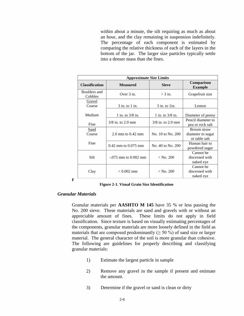
sample. Figure 2-1 provides the defined particle sizes for
each component and a common reference to aid in
identifying the various particle sizes.
2) Sedimentation/Dispersion. This test is done by shaking a
portion of the sample into a jar of water and allowing the
material to settle. The material settles in layers. The gravel
and coarse sand settle almost immediately, the fine sand
Page 20
2-6
within about a minute, the silt requiring as much as about
an hour, and the clay remaining in suspension indefinitely.
The percentage of each component is estimated by
comparing the relative thickness of each of the layers in the
bottom of the jar. The larger size particles typically settle
into a denser mass than the fines.
F
Figure 2-1. Visual Grain Size Identification
Granular Materials
Granular materials per AASHTO M 145 have 35 % or less passing the
No. 200 sieve. These materials are sand and gravels with or without an
appreciable amount of fines. These limits do not apply in field
classification. Since texture is based on visually estimating percentages of
the components, granular materials are more loosely defined in the field as
materials that are composed predominantly (≥ 50 %) of sand size or larger
material. The general character of the soil is more granular than cohesive.
The following are guidelines for properly describing and classifying
granular materials:
1) Estimate the largest particle in sample
2) Remove any gravel in the sample if present and estimate
the amount.
3) Determine if the gravel or sand is clean or dirty
Approximate Size Limits
Classification Measured Sieve Comparison
Example
Boulders and
Cobbles Over 3 in. > 3 in. Grapefruit size
Gravel
Coarse
Medium
Fine
3 in. to 1 in.
3 in. to 1in. Lemon
1 in. to 3/8 in.
1 in. to 3/8 in. Diameter of penny
3/8 in. to 2.0 mm 3/8 in. to 2.0 mm Pencil diameter to
pea or rock salt
Sand
Coarse
Fine
2.0 mm to 0.42 mm No. 10 to No. 200
Broom straw
diameter to sugar
or table salt
0.42 mm to 0.075 mm No .40 to No. 200 Human hair to
powdered sugar
Silt -.075 mm to 0.002 mm < No. 200
Cannot be
discerned with
naked eye
Clay < 0.002 mm < No. 200
Cannot be
discerned with
naked eye
Page 21
2-7
4) If the sample contains appreciable fines, determine if the
fines are silty or clayey as outlined in Silt-Clay Material
Determination of clean verses dirty may be made by two simple field tests
as follows:
1) Settlement Rate Test -- Place a small amount of the
material in a container filled with water. The water clears
in 30 seconds for clean sands and remains cloudy for dirty
sands.
2) Dust Formation Test -- Dry out the granular material if
moist. Sift the dry, granular material through your fingers
and let the material fall on a hard, clean surface. If large
amounts of silt and clay are present, the material that
strikes the hard surface is dust.
Silt-Clay Materials
Silt-clay soils are composed predominantly of grains that visually
cannot be distinguished in size. Besides the general techniques
described earlier, several field tests may be used to distinguish silty
from clayey soils as follows:
1) Plasticity Test -- The ability to be molded within a certain
range of moisture contents is termed plasticity. Plasticity is
dependent upon the percentage and type of clay
component, and therefore requires differentiation between
silt (non-plastic fines) and clay (plastic fines).
For the ribbon/thread test, a roll of soil moist enough to
have workability, approximately 1/2 in. to 3/4 in. in
diameter and about 3 in. to 5 in. in length, is pressed
between the thumb and index finger into a ribbon of about
1/8 in. thick. The longer the ribbon may be formed before
the soil breaks under the soil’s weight, the higher the
plasticity of the soil. Highly plastic clays may be ribboned
to 4 in. longer than the original material. Clay of low
plasticity may be ribboned only with some difficulty into
short lengths. Predominately silty soils do not ribbon or
have ribbons that are delicate, softer, and easily crumbled.
Non-plastic materials cannot be ribboned.
Page 22
2-8
Plasticity Length of Ribbon (in.)
Non Plastic 0
Slightly Plastic to Plastic
0 – ½
½ - 1
¼ - 1
0 - 1
Plastic to Highly Plastic 1 – 2
Highly Plastic > 2
2) Dry Strength / Breaking Test -- The dry strength/breaking
test is normally made on a dry pat of soil about 1/2 in. thick
and about 1 1/4 in. in diameter that has been allowed to air
dry completely. Attempts are made to break the pat
between the thumb and fingers. Very highly plastic clays
are resistant to breakage and highly plastic clays are broken
with great effort. Caution is exercised with highly plastic
clays to distinguish between shrinkage cracks, which are
common in such soils, and a fresh break. Clays of low
plasticity may be broken with ease, therefore, clayey soils
have medium to very high dry strength. Silty soils break
readily and have no strength (non-plastic) to medium
strength (slightly plastic). Non-plastic soils have very little
dry strength, crumbling on being picked up by the hands.
3) Shaking / Dilatency Test -- In the shaking / dilatency test, a
pat of soil about 3/4 in. in diameter is moistened to a putty-
like state and placed in the palm of the hand. The hand is
then shaken vigorously or jarred on a table or other firm
object. If the surface of the sample begins to glisten, this is
an indication that moisture within the sample has risen to
the surface. When this does not occur, the soil is probably
clayey. Where this occurs sluggishly or slowly, the soil is
predominately silty, perhaps with a small amount of clay.
For silts or very fine sands, the moisture rises to the surface
rapidly, and the test may be repeated over and over by
simply remolding and then reshaking the pat. This test is
not generally done by INDOT.
Page 23
2-9
Marl, and Peat
Marl and peat may be identified by visual inspection, color, smell, density,
and compressibility. Peat is a highly organic soil characterized by
undecayed to decaying plant matter, which gives the material a fibrous
texture. Marl tends to have animal remains, predominantly shells.
Organic soils are dull brown to black in color, spongy, and have a slight to
strong odor of decay.
Modifying Terms
When describing soils in the field, modifiers are used and included in the
description, when appropriate. These modifiers are either textural or
general.
Textural modifiers are used to indicate components that were not
considered in the textural classification of the material. These include
such materials as rock fragments, gravel particles, pieces of shale, etc. and
are indicated as follows:
1) Trace amounts -- component comprises 0-10 % of soil
2) Little -- component comprises 11-19 % of soil
3) Some -- component comprises 20-35 % of soil
4) And -- component comprises 36-50 % of soil
General modifiers may be very helpful and accompany the soil description
whenever possible. They are noted in parenthesis after the usual soil
classification.
Some examples of general modifiers are:
1) Fill material
2) Apparently natural ground
3) Peat
4) Marl
5) Till
6) Old lake bed (lacustrine)
Page 24
2-10
Examples and Interpretations of Field Descriptions
All soil descriptions follow the same format. The color is described first,
then the moisture, followed by consistency or density, and finally the
textural classification, which is in all capital letters. The following is an
example from an actual soil-boring log:
1) Topsoil (visual)
2) Brown, moist, very loose to medium dense, LOAM
3) Brown, moist, very loose, SANDY LOAM
4) Gray, moist, medium dense to loose, LOAM with little
organic matter (LOI = 8.5 %)
5) Gray, moist, very soft to medium stiff, SILTY CLAY
LOAM
6) Brown and gray, weathered SHALE with interbedded
layers of sandstone (visual), % recovery, and Rock Quality
Description.
Number 1 is the topsoil.
Number 2 is a granular material. Granular soils have the density
described, not the consistency. A range of densities may be used to
describe the soil.
Section 903.02 defines a loam as having as much as 50 % sand and gravel.
Therefore, since loam was considered granular, the sand-sized material
probably was around 50 %. Since the material obviously had large
amounts of fines (≈ 50 %), the material was classified as a loam as
opposed to a sandy loam. Obviously, the sand was dirty.
Number 3 is a granular material. Sandy loams have between 50-80 %
sand and gravel. This material was obviously granular to be classified as a
sandy loam. Since the density was described as very loose, the material
had considerably fewer fines than the sample above; however, there was
enough to classify the sand as dirty and consequently the material is a
sandy loam as opposed to sand.
Page 25
2-11
Number 4 is a granular material. Again, the material was composed
predominantly of sand. The sample had a textural modifier, concerning
the organic matter (LOI = 8.5 %). The LOI is the "loss on ignition" of
organic material (AASHTO T 267). The sample was tested in the
laboratory for organic content and had obvious organic material in the
material.
Number 5 is a silt-clay material. The consistency of the material was
described as opposed to the density. Again, a range of consistencies was
given as opposed to a single consistency. The material obviously had
considerably less sand than the previous samples and the fines were
predominantly silt, not clay.
Number 6 is the top of bedrock.
The granular soils were apparently not gravelly. If they were gravelly (≥
20 %), the textural modifiers “with some gravel” or “and gravel” would
have been used. No gravel was found in the soils at all since no textural
modifiers were used.
Based on visual classifications and laboratory testing, Geotechnical
Engineers refine the field boring logs.
Page 26
2-12
Classification % Sand &
Gravel % Silt % Clay
Sand 80 - 100 0 - 20 0 – 20
Sandy Loam
Loam
Silty Loam
50 – 80
30 – 50
0 - 50
0 – 50
30 – 50
50 - 80
0 – 20
0 – 20
0 - 20
Silt
Sandy Clay Loam
Clay Loam
Silty Clay Loam
0 – 20
50 – 80
20 – 50
0 - 30
80 – 100
0 – 30
20 – 50
50 - 80
0 – 20
20 – 30
20 – 30
20 - 30
Sandy Clay
Silty Clay
Clay
50 – 70
0 – 20
0 - 50
0 – 20
50 – 70
0 - 50
30 – 50
30 – 50
30 - 100
Fig. 2-1. Soil Classification
Page 27
2-13
ROCK AND SHALE EMBANKMENT
Rock and shale embankment is covered in Section 203.20. INDOT
considers three categories of rock and shale as follows:
1) Rock
2) Shale, Shale and Soft Rock Mixtures, or Soft Rock
3) Shale and Thinly Layered Limestone
In order to understand the differences in the materials, a greater
understanding of rocks, Indiana geology, and the INDOT specifications is
required.
PRINCIPAL ROCK TYPES
There are three general classes of rock: Igneous, Sedimentary, and
Metamorphic. All of the rocks on earth fit into one of these classes.
Igneous rocks are rocks that were formed from cooled molten rock
material called magma and are considered the original rock type. The rate
of cooling and chemical composition of the magma determined the type of
igneous rock. Examples of igneous rocks are granite and basalt.
Sedimentary rocks are rocks that were formed from the accumulation,
compaction, and cementation of fragmented earth materials, organic
remains, and or chemical precipitates. These materials are collectively
called sediments, hence the name. Sedimentary rocks are derived rock
types that require the weathering and erosion of existing rocks for their
formation. Examples of sedimentary rock are sandstone, limestone, and
shale.
Metamorphic rocks are rocks that were formed from existing rocks that
have been subjected to heat and/or pressure. This process metamorphoses
or changes the rock mineralogically, texturally, and structurally. An
existing metamorphic rock may be metamorphosed again by the geologic
conditions. Examples of metamorphic rocks are marble (metamorphosed
limestone), slate (metamorphosed shale), and gneiss (metamorphosed
granite).
ROCK
Rock, as defined in AASHTO M 146, does not distinguish between soft
rock and hard or durable rock. Section 203.03 defines what materials
would classify as rock. Generally, materials meeting 203.03 are to be
treated in accordance with section 203.20(a) rock embankment. This is
not always the case, however, since some shale requires blasting as
Page 28
2-14
opposed to ripping with a bulldozer and all shale is covered under Section
203.20(b) unless written permission is obtained to incorporate shale in
accordance with Section 203.20(a). Therefore, careful consideration of
the type of rock material in question is required before incorporating the
material in embankments. When in doubt as to which section applies to
the material, the Area Engineer, District Construction Director, District
Testing Engineer, or the Office of Geotechnical Engineering is consulted.
SHALE, SHALE AND SOFT ROCK MIXTURES, OR SOFT ROCK
Shale is a sedimentary rock composed of clay, silt, or mud that is finely
laminated. Shale appears in a variety of colors and may be highly variable
in hardness. Shale belongs to a class of sedimentary rocks termed
mudrocks.
The problem with mudrocks is that this material has an affinity for water.
Because of the high clay content in mudrocks, they readily absorb water;
however, these types of rocks are impermeable and do not allow the water
to leave. This absorption of water results in a significant volume change
in the material, causing the material to slake. Slaking is defined as the
crumbling and disintegration of clay-rich materials when exposed to
water. Clay-rich rocks, or argillaceous rocks, readily slake under alternate
cycles of wetting and drying. Therefore, all mudrocks are properly treated
in accordance with Section 203.20 (b).
Because of the propensity of shale or soft rock to slake, embankments
constructed with these materials may experience problems as follows:
1) Settlement
2) Heaving, either from frost or alternating cycles of wetting
and drying
3) Slope instability
4) Surface and subsurface erosion
Large pieces of unslaked material produce large voids when they
eventually slake. The large voids cause settlement and possible eventual
failure of the fill or embankment.
Heaving may also induce embankment failure. Shale and soft rock have a
tendency to heave when an increase in moisture occurs or during freeze-
thaw conditions. Heaving loosens the material, thereby decreasing the
compaction of the lifts so the material no longer has the proper density.
Again, settlement and failure of the fill may happen.
Page 29
2-15
SHALE AND THINLY LAYERED LIMESTONE
Shale and thinly layered limestone may be common in some geographical
areas in Indiana. When two rock types such as shale and limestone are
found mixed together, they are termed interbedded.
Interbedded shale and limestone is essentially shale as defined in Section
203.20(b) and rock as defined in Section 203.20(a) intermixed. Therefore,
the potential for slaking is present. Section 203.20 (c) describes the
construction requirements for these materials.
OTHER EMBANKMENT AND FILL MATERIALS
Embankment and fill materials may or may not be aggregates and
therefore are not required to originate from a Certified Aggregate Producer
(CAP). In the case of borrow, there is no testing requirement for
acceptance; however, the top 2 ft below the pavement is required to meet
the requirements of the Section 207.03.
BORROW
Borrow is defined in Section 203.08
B-BORROW
B-borrow is defined in Section 211.02.
STRUCTURE BACKFILL
Structure backfill is defined in Section 904.05.
AGGREGATE MATERIALS
Aggregate materials are required to originate from a Certified Aggregate
Producer in accordance with Section 917. Since these materials are
certified, no testing for gradation by INDOT is required.
AGGREGATE BASE
The requirements for this material are listed in Section 301.02.
SUBBASE
The requirements for these materials are listed in Section 302.02.
AGGREGATE PAVEMENTS OR SHOULDERS
The requirements for these materials are listed in Section 303.02.
SYNTHETIC MATERIALS
Page 30
2-16
Synthetic materials are by-products or waste materials that have been
reclaimed and/or processed to be used in highway construction. Generally
their usage is very limited and restricted.
COAL COMBUSTION BY-PRODUCTS.
Coal combustion by-products are recovered from coal-fired power plants
and include fly ash, bottom ash, and boiler slag. The requirements for
these materials are included in Recurring Special Provision 203-R-360.
Page 31
3 Excavation
Common Excavation Submitting Samples
Preparing the IT 530
Rock Excavation Exploration Drilling
Rock Pre-Splitting
Explosives
Primary Blasting
Restrictions
Finished Grade
Unclassified Excavation Waterway Excavation
Class Y Excavation
Class X Excavation
Wet Excavation
Dry Excavation
Foundation Excavation, Unclassified
Disposal of Excavated Material Suitable Material
Unsuitable Material
Excess Material
Borrow
Contractor Responsibilities
Page 32
Preparing a Borrow Pit
Peat Excavation Treatment of Existing Fills
Treatment by Removal
Treatment by Displacement
Peat Disposal
Page 33
3-1
CHAPTER THREE:
EXCAVATION
During the construction of a highway or bridge, existing materials may be
required to be removed. These materials occupy the space in which a new
highway or bridge is planned. Therefore, they are removed or
"excavated." The types of excavation are:
1) Common
2) Rock
3) Unclassified
Some materials excavated may be suitable for use in construction of
embankment. Some are not and are disposed of completely.
COMMON EXCAVATION
Common excavation is the most frequently encountered type of
excavation. The Specifications state that, "Common excavation shall
consist of all excavation not included as rock excavation or excavation
which is otherwise classified and paid for, including asphalt type
pavement and all rippable materials".
Common excavation is the excavation of soil materials from within the
contract limits; however, this excavation is not limited to soil materials
and may include existing HMA pavement. If the material is indicated on
the plans and is not a concrete pavement or another defined excavation,
then the material is considered common excavation.
Section 203 further defines embankment construction as the excavation,
hauling, and disposal or compaction of all material. Because compaction
of the material is included in common excavation, soil samples are
required to be obtained. These samples are submitted to the appropriate
testing laboratory for determining compaction requirements and moistures.
SUBMITTING SAMPLES
The manner of sampling and the number and the size of samples required
depends upon two conditions:
Page 34
3-2
1) The number of different soil types used on the contract.
The submitter investigates each cut and borrow pit to
determine the soil types. Only samples of the different
types encountered are submitted.
2) The method the Contractor expects to use in the removal
and placing of the soil. If each type is worked separately,
the soil is required to be sampled separately. However, if
the Contractor expects to blend soil types, the soils are
sampled accordingly. Blending may occur during
excavating or placing. Therefore, communication with the
Contractor is essential.
If relatively few samples are to be secured, a 5 in. auger is a satisfactory
tool for securing samples. Three foot extension sections of pipe may be
required to reach the desired depth. The grading Contractor is required to
supply a backhoe with an operator for securing a large number of samples
or samples at depths greater than 5 ft.
The grade Technician may be required to determine where the samples are
to be taken, obtain the samples, and submit the samples. Each soil sample
is required to be a minimum of 25 lb and each granular material a
minimum of 65 lb. A small portion of each sample is required to be
retained for later reference.
PREPARING THE IT 530
When the samples are submitted to the District laboratory, they are
accompanied by an IT 530 for each sample. The following special
information for each sample is reported on the IT 530:
1) Centerline station and offset
2) Centerline station and offset for adjacent borrow pits
3) Elevation
4) Field office telephone number
5) Copies of applicable special provision sheets
6) Referenced specifications
7) Intended use
8) Description of soil as to texture, color, visual classification,
moisture content, etc.
Page 35
3-3
The appropriate laboratory determines the maximum density, optimum
moisture content and should also report the sulfate content. These results
are sent to the PE/PS for use in determining in-place soil densities.
ROCK EXCAVATION
Rock excavation consists of the excavation of igneous, metamorphic, and
sedimentary rock and boulders or detached stones having a volume of 1/2
yd3 or greater. The material for this type of excavation is removed by
blasting, by power shovel with a bucket that has a minimum capacity of 1
yd3, or by other equivalent powered equipment. Unless otherwise
specified or directed, the following criteria is used in excavating the
material.
EXPLORATORY DRILLING
Exploratory drilling may be required to determine the existence of cavities
and possible sink holes in cut sections. These holes are 1 1/2 in. in
diameter, and drilled on centerline at 100 ft intervals to a point which is 7
ft below the proposed grade. If a cavity or sink hole is found then
additional holes are drilled along the edges of the pavement at 25 ft
intervals. These holes are also drilled to 7 ft below the proposed grade. If
the cavity has less than 5 ft of cover, then the cover is removed and the
cavity treated as set out in the plans or as directed.
ROCK PRE-SPLITTING
The rock is pre-split by the use of drilling and explosives. The work is
done in such a manner that minimum breakage occurs outside the neat
lines of the typical cross section. The holes for this operation are from 2
in. - 4 in. in diameter, spaced 3 ft apart, and drilled 2 ft below the
established grade of the cut or the predetermined bench elevation. The
maximum depth of a pre-split lift is 30 ft. If a cut section requires more
than one lift, the holes are drilled in such a manner that the specified offset
for each succeeding lift is obtained. A horizontal distance of 2 ft off the
back side of the paved side ditch line is required.
The pre-split face shall deviate no more than 6 in. from the front line and 1
ft from the back line of holes. The pre-splitting operation is kept well in
advance of the regular blasting operations. The line holes are to be fired
before the main excavation is blasted. There is no direct payment for pre-
splitting because the cost is included in the cost of excavation.
Page 36
3-4
EXPLOSIVES
The explosives to be used and the method of loading depends on the type
of material to be blasted. A single strand of detonating chord or a solid
column of dynamite may be used. The type used is required to be capable
of pre-splitting the material with a minimum breakage outside the
excavation area.
PRIMARY BLASTING
The holes for the primary blasting are drilled at least 6 ft away from the
pre-split face. If additional charges are required, the holes are placed at
half the distance of the full depth holes. These holes are drilled to a depth
2 ft above the pre-split face.
RESTRICTIONS
The Contractor is required to restrict the amount of explosives used near
structures, rock formations, or other property that may be damaged.
Adequate seismograph readings should be taken during blasting operations
to document the impact on nearby buildings. The contractor should also
document the existing condition nearby buildings prior to blasting
operations.
FINISHED GRADE
The final breakage of rock is required to conform to or closely
approximate the slope lines indicated on the plans. The final slopes are
required to be left reasonably smooth and uniform with all loose and
overhanging rock removed. Unless otherwise permitted, no rock is
allowed to project more than 1 ft beyond the established slopes. If a
natural seam intersects an established slope, permission may be granted to
follow the seam face for an approved distance. If the Contractor provides
a finished slope which is equal or superior to that which is obtained by
pre-splitting, machine methods to establish final slopes may be used. The
rock is excavated to the required elevation for the full width of the
roadway as indicated on the plans or as directed. The final surface of the
rock excavation is required to have proper drainage. If the rock is
excavated below the required elevation, the rock excavation is backfilled
to the subgrade elevation with crushed stone, spalls, subbase material, or
other granular material.
Page 37
3-5
UNCLASSIFIED EXCAVATION
Unclassified excavation consists of the excavation of and proper disposal
of any type of material that is encountered during the progress of the work.
WATERWAY EXCAVATION
Waterway excavation consists of excavation and the proper disposal of
material encountered in the clearing of the waterways, making channel
changes, or a combination of the two. The excavation does not include
Class Y excavation or the excavation made for a structure as set out in
Section 206. Waterways are excavated only according to the plans and the
requirements of the 401/404 permit. No excavation should be allowed that
is not shown on the 401/404 permits. Any discrepancies between the
permit and plans should be discussed with the AE.
CLASS Y EXCAVATION
While conducting normal waterway excavation, material may be
encountered such as rock or material which consists of hard ledge rock,
hard shale, conglomerate, concrete, masonry, or any similar material
which is not part of the existing structure as indicated on the plans. If the
material cannot be reasonably removed by any other method, the material
is removed by blasting. This excavated material is defined as Class Y
excavation. Section 203.07 defines material that may not be considered
Class Y excavation.
CLASS X EXCAVATION
One or more of the following materials encountered within the limits of
foundation excavation are defined as Class X excavation.
1) Solid rock, hard ledge rock, slate, hard shale, or
conglomerate. Because the material cannot be reasonably
removed by any other method, blasting or pneumatic or
equivalent tools are required for removal.
2) Loose stones or boulders which are greater than 1/2 yd3 in
volume.
3) Concrete, masonry, or similar materials which are parts of
an old buried structure that was not shown on the plans.
4) Timber grillages, old foundation piling, buried logs,
stumps, or similar material that extend beyond the limits of
excavation and are required to be cut off to be removed.
These materials are removed back to the cofferdam limits
and paid as Class X excavation.
Page 38
3-6
Hard pan is not considered as Class X excavation. The limits of Class X
excavation are the neat lines of the footer unless the excavation lies above
another type of excavation whose limits are different. In this case, Class
X excavation is paid to the limits of the underlying material.
WET EXCAVATION
Wet excavation is that portion of the foundation excavation, except Class
X, which is below a horizontal plane designated on the plans as the upper
limit of wet excavation and above the bottom of the footing. If the
elevation of the upper limit of wet excavation is not indicated on the plans,
an elevation of 1 ft above the elevation of low water level is used.
DRY EXCAVATION
Dry excavation is that portion of foundation excavation, except Class X,
which is above the upper limit of the wet excavation.
FOUNDATION EXCAVATION, UNCLASSIFIED
Foundation excavation, unclassified includes all the work for wet
excavation or dry excavation if no pay item is included for these items,
regardless of whether or not water is encountered. Class X is not included
in foundation excavation, unclassified.
If no upper limit of foundation excavation, unclassified is shown on the
plans, the upper limit is the original ground, except where waterway
excavation, common excavation, or other classified excavation overlaps
the area of foundation excavation.
DISPOSAL OF EXCAVATED MATERIAL
Excavated material may be classified as follows:
SUITABLE MATERIAL
If the material removed is suitable, then the material may be used for
construction of embankments, shoulders, special fills, or other places as
specified or directed depending on the nature of the fill.
UNSUITABLE MATERIAL
If the material is unsuitable for use in the embankment, the material is
removed from the right-of-way. No unsuitable material can be disposed
on private property without an approved Form IC 203.
Page 39
3-7
EXCESS MATERIAL
Any excess excavated material that cannot be constructively used within
the contract limits may be disposed of off the right-of-way, or used as
directed to widen embankments or flatten fill slopes.
Excavation obtained from within the right-of-way and planned to be used
in the embankment may be wasted and replaced with borrow if permission
is obtained. However, the borrow is not paid for.
BORROW
Borrow is a material obtained by the Contractor from locations outside of
the right-of-way to complete the planned grading section. Frequently this
material is obtained from properties adjacent to the right-of-way. Many of
the areas that are "borrowed" from become ponds or small lakes. Hence
the term "borrow pit".
Material such as river or lake deposit, cinders, or a soil mixture with a
high organic content are not allowed. Borrow material is required to be
free of substances that:
1) Form putrefying (rotting) deposits
2) Form deleterious (harmful) deposits
3) Produce toxic concentrations or combinations that may be
harmful to human, animal, plant, or aquatic life
The following borrow materials that are not suitable for the growth of
vegetation may be used:
1) Recycled materials such as coal combustion products,
recycled foundry sand, granulated slag, etc.
2) Dune sand
3) B-Borrow
4) Other granular material
When these materials are used they may not be placed within 1 ft of the
required finished grade of the shoulders and slopes. The final 1 ft is
required to be material suitable for the growth of vegetation. This material
is required to be free from clods, debris, and stones.
Page 40
3-8
CONTRACTOR RESPONSIBILITIES
When offsite borrow or the disposal of excavated material is necessary,
the Contractor is required to comply with the requirements spelled out in
Section 203.08, Borrow or Disposal. These requirements are outlined on
page 1-4. The Contractor will need to request approval of the borrow or
disposal site at least 14 days prior to when it will be used. The
requirements for the contractor request are in Section 203.08.
PREPARING A BORROW PIT
Section 203 places limits on the location, planned excavation, and control
of the drainage of the borrow pit. Upon approval of the site by all parties
involved the Contractor may proceed with clearing the borrow pit site.
Soil samples of the pit are taken and forwarded to the District Testing
Department. Before any borrow material is removed from the pit, a base
line is required to be established and the original cross-sections taken.
The base line is established through or near the proposed borrow pit with
the extremities of the line referenced outside of the excavated area.
Sections should be taken well outside of the expected excavation area so
the quantity can be determined if the amount of borrow is overrun. The
reference line will need to be reproduced after the borrow material is
removed. The quantity of borrow paid to the contractor will be the
difference from the original section and the final sections after the material
is removed.
Precautions are to be taken to ensure that the references are not disturbed.
In establishing a base line, consideration is given to the topography, the
line of the cross sections, and the possibility of extending sections, if
necessary. If the borrow pit includes a large area, an auxiliary line is run
parallel to the base line to properly align the cross sections. Unless written
permission is granted, there is no excavation below the elevation of the
adjacent properties in a borrow pit within 150 ft of the nearest right-of-
way line of an existing highway. A sketch is required to be made of the
borrow pit layout in the permanent field notes. A description of the
location of the borrow pit is placed on the sketch, such as, the number of
feet right or left of a roadway station. The name of the property owner is
also placed on the sketch.
PEAT EXCAVATION
Peat is partly decayed plant matter that has collected in swamps and
marshes over long periods of time and is generally the first stage in the
formation of coal. Dried peat varies from a light yellow-brown substance
to deeper layers of dark brown, compact material which looks like brown
coal. Peat is not suitable for foundations of roadways because the material
is unstable and subject to settlement when additional embankment is
Page 41
3-9
placed upon the deposit. Therefore, peat is required to be removed from
under the roadway.
Peat excavation is the removal and satisfactory disposal of peat, marl, or
any other unsuitable material and any overlaying material. Extremely soft
organic silt is found in lake bottoms and in static areas along river bottoms
(flood plains). Marl is a water-deposited sand, silt, or clay containing
calcium carbonate. Marl is sometimes found immediately below peat.
In rolling country where the ground rises sharply from the peat deposit,
soils have often been washed over the edge of the original peat deposit.
Some peat may therefore be trapped under what appears to be the soil
perimeter of the peat deposit. This also is considered to be peat
excavation.
Removal of peat deposits may be done in several ways. Methods of
treatment may be shown on the plans, as directed, or by other methods
outlined in the Specifications. Because treatments detailed on the plans,
or as directed, are not all uniform in application, only the methods outlined
in the Specifications are discussed.
The Specifications detail three methods for treatment:
1) Treatment of existing fills
2) Treatment by removal
3) Treatment by displacement
TREATMENT OF EXISTING FILLS
Treatment of existing fills is a method used to change a fill over an
existing peat deposit. The change may be in height and/or width.
Treatment of existing fills may be done by several means and is usually
predetermined and outlined in the contract plans.
TREATMENT BY REMOVAL
The method of treatment by removal consists of completely removing the
objectionable material by machine operations. This method is usually
used when the following conditions exist:
1) The peat deposit is small in size
2) The peat deposit is shallow in depth
3) The peat deposit limits are completely within the
construction limits or right-of-way
Page 42
3-10
The following takes place during the method of treatment by removal:
1) New original cross-sections are taken. The entire area may
have settled since the original survey.
2) The width of excavation is to be the full toe of slope to toe
of slope width of the proposed embankment.
3) Final cross-sections are taken after the excavation is
completed.
4) Backfilling of the peat excavation follows as soon as
possible to minimize the occurrence of slides.
5) If water is not present, the excavation may be backfilled
with borrow or common excavation.
6) If water is present, the backfill is required to be B Borrow
placed by end-dumping to an established grade of
approximately 2 ft above free water level.
TREATMENT BY DISPLACEMENT
Treatment by displacement is the most commonly used procedure for
excavation of peat. This procedure is frequently used under the following
conditions:
1) The peat deposit is large in size
2) The peat deposit is deeper than 10 ft
3) Water is present at all times
4) The free water level is high
The following steps are usually followed during this method of treatment,
if conditions permit:
1) Each end of the deposit is removed until the depth of the
peat excavation is greater than 10 ft. This may be subject
to change as directed. If conditions permit, the upper
portion of peat is excavated across the remainder of the
deposit. Excavation of this upper level begins at one end
and continues ahead of the displacement-backfill operation.
The free water level usually controls the depth of this
operation. Displacement-backfill operation is also known
as "surcharge".
Page 43
3-11
2) After the completion of the excavation, cased test holes are
placed. These test holes determine the extent of peat
displacement and are also used to determine final
measurement of the excavation.
The surcharge operation is the most difficult portion of the treatment to
control. The weight of the surcharge literally pushes or squeezes the peat
from the deposited area. A crane(s) with a drag line assists the surcharge
procedure by removing the peat from in front of the surcharge. Since a
properly constructed surcharge is very important, several guidelines are
followed during the construction of the surcharge:
1) The surcharge is constructed of B Borrow.
2) The top of the surcharge is constructed and maintained to a
width equal to the full shoulder width of the embankment.
3) The height of the surcharge is the same as the depth of peat
being excavated. The original ground is the reference
elevation for measuring the peat depths and the surcharge
heights.
4) The top of the surcharge is approximately level.
5) The length on the top of the surcharge is at least 2 times the
depth of the peat being treated.
6) The surcharge is maintained and pushed forward as
directed.
7) The crane operation is coordinated with the rate of placing
the surcharge.
PEAT DISPOSAL
Once the peat deposit is excavated, by either removal or displacement, the
excavated peat shall be disposed of in accordance with 203.08.
Page 44
4 Excavation Construction
Requirements
General Preparation
General Requirements
Erosion Control
Lifts
Equipment Hauling
Spreading
Compacting
Page 45
4-1
CHAPTER FOUR:
EXCAVATION CONSTRUCTION
REQUIREMENTS
GENERAL PREPARATION
Prior to beginning excavation, grading, or embankment operations in any
area, the following items are required to be completed:
1) Clearing and grubbing is conducted. This includes the
removal of all perishable material such as tree roots,
stumps, sod, weeds, agricultural debris, etc.
2) Check sections are taken and checked satisfactorily with
those on the plans. On contracts with construction
engineering, the Contractor is responsible for securing
check sections. The method of checking original cross
sections is outlined in the General Instructions to Field
Employees.
3) After the previous items have been completed, the
Contractor proceeds with scalping in areas where
excavations are to be made, or embankments are to be
placed. Another common term for scalping is stripping.
Scalping is the removal of the upper 4 in. of the soils.
Removal is necessary to ensure that decay able vegetation
is not incorporated into an embankment. Although 4 in. is
the maximum depth, top soils containing large quantities of
humus to a depth greater than 4 in. are removed until
suitable materials are exposed. The removed topsoil should
be stock piled on site, this material will be spread as the
upper layer on fill in order to get vegetation to grow. This
is necessary to get the notice of termination, NOT, to close
the Rule 5 permit. Scalping is completed to the limits the
area where excavations are to be made or embankments are
to be placed. The grading operations is inspected closely
for unsuitable material. Roots and other large perishable
objects are removed and stockpiled outside of the
construction limits for later disposal.
4) All pronounced depressions left in the original ground
surface by removal of objectionable material from within
embankment limits are filled with acceptable material and
compacted to the density required for the embankment.
Page 46
4-2
The upper 6 in. of the original ground is compacted with a
roller weighing no less than 10 t, or with other approved
compacting equipment.
5) The final step before embankment placement is
proofrolling. This work is done with a pneumatic tire roller
(Figure 2-1) with a minimum tire size of 7:50 by 15 in
accordance with Section 409. Other approved equipment,
such as a fully loaded tri-axle dump truck, may be
substituted for the pheumatic tire roller. One or two
complete coverages is required, as directed. This procedure
also reveals all spongy and yielding materials which are not
compacted. If soft areas are identified that will result in
soft areas under the embankment they should be removed.
The volume removed should be measured and paid in the
common excavation item as undercutting. Judgment should
be used in identifying these areas considering the height of
embankment to be placed at that location. Identified areas
within the proposed embankment are removed. The
locations of spongy and yielding material may be detected
visually.
After proofrolling has been completed and all soft or
unstable areas have been corrected, the area is ready for
placement of the new embankment.
Figure 4-1. Pneumatic Tire Roller
Page 47
4-3
GENERAL REQUIREMENTS
Excavated material that is suitable for embankment construction is placed
in the embankment before placing any borrow material. This means that
ditches are excavated first, since much of common excavation is derived
from ditch cuts. The construction of ditches first also provides drainage
for the embankment area. The roadway embankments are maintained
higher at the center to promote drainage of the roadway.
TEMPORARY EROSION CONTROL
Once the ditches have been completed, the Contractor begins placement of
temporary erosion control devices as soon as possible. Failure to do so
may cause pollution to drainage ditches, streams, and rivers adjacent to the
project and is a violation of 327 IAC. Some different types of temporary
erosion and sediment control devices may include:
1) Perimeter protection
2) Drainage barrier at swale
3) Slope protection – interceptor ditches and slope drains
4) Sediment control in side ditches – straw bale ditch check,
riprap ditch check, ditch sediment trap, or culvert pipe
protection
5) Sediment basin
6) Inlet protection – curb inlet protection and drop inlet
protection
These erosion control features are maintained until permanent erosion
control features are placed. The need for erosion control devices is
determined in the planning stages of the project, and erosion control
devices are outlined and detailed on the construction plans. A storm water
quality control plan shall be submitted in accordance with Section 205 for
those areas not included in the plans or as necessary for changes initiated
by the Contractor. Items to include consist of sequencing of operations,
stockpile sites, equipment storage sites, plant sites, borrow and disposal
areas, and haul roads as well as any revision to the features shown in the
plans. All appropriate erosion control items shall be in place prior to
disturbing the project site. A copy of the amended plan should be provided
to the PE/S. The Technician is responsible for ensuring that these devices
are being maintained. Inspection of control devices is especially
important during and after periods of rainfall which may cause damage to
Page 48
4-4
the devices. Sediment basins are required to be cleaned, dikes or dams
reconstructed, if damage has reduced the effectiveness of these devices.
LIFTS
During the construction of an embankment, each lift being placed has
certain factors which are required to be considered:
1) Lifts are required to extend transversely over the entire
embankment area between slope stakes. Doing this ensures
that the outside slopes of the embankment are compacted as
well as the middle of the embankment. The higher the fill,
the more critical this becomes.
2) The fill width is required to be checked as the fill
progresses. Failure to do so may cause fat or bellied
slopes.
Fat slopes are slopes which contain excess material or
exceed the planned slope. Bellied slopes are slopes that do
not contain enough material and these slopes are detected
by viewing the slopes longitudinally. Bellied slopes are
required to be corrected as the embankment is being built.
Sidecasting is avoided as a solution since this usually
develops a fill slough or slide at a future date.
EQUIPMENT
Equipment required for placing embankment consists of four categories;
1) Hauling equipment
2) Spreading equipment
3) Compacting equipment
4) Moisture control equipment
HAULING
The method of hauling embankment material is determined by the
Contractor and is based upon the following construction factors.
1) Type of material
2) Source of material
Page 49
4-5
3) Conditions or obstacles between the source and area of
placement
4) Availability of equipment
The equipment used for hauling includes:
1) Dump trucks
2) Earthmovers
3) Quarry trucks
Earthmovers (Figure 4-2) are frequently used for hauling embankment
material. There are various sizes and models of earthmovers.
Earthmovers are used in excavating, hauling, and placement of soil
materials that are adjacent to or on the contract. When common
excavation is required to be hauled across a bridge structure or when
borrow material is obtained from a remote source, or hauling takes place
over a road that is open to the public, dump trucks are used. Quarry trucks
are used only in rock excavation.
Figure 4-2. Earthmover
SPREADING
Because embankments are to be constructed in uniform layers, spreading
equipment is necessary. Placing uniform layers may be done with several
types of equipment or groups of equipment. The most common are the
motor grader and the bulldozer. If soil conditions are suitable,
Page 50
4-6
earthmovers may also be considered as spreading equipment. This is done
by the earthmover operator controlling the discharge of the materials in
such a manner to create a uniform layer. Because soil conditions may
change dramatically, the earthmover is not the only spreading device
necessary.
Another method of leveling layers uses a sheepsfoot compactor with a
blade (Figure 4-3). This equipment may be used instead of a motor
grader. This is especially true on small grading projects.
Figure 4-3. Sheepsfoot Compactor with Blade
A piece of equipment that may also be used during the spreading operation
is the disk (Figure 2-4). Although the disc does not level the soil, this
equipment is helpful in creating a uniform layer. The disc is used for:
1) Breaking up lumps, slabs, and clods
2) Aerating material to remove excess moisture
3) Incorporating water to increase moisture
Page 51
4-7
Figure 4-4. Disk
COMPACTING
Compacting equipment requirements vary from contract to contract. A list
of the types of compactors which are most commonly used include:
1) Three wheel roller
2) Smooth drum vibrator roller
3) Vibratory tamping roller (Figure 4-5)
4) Static tamping roller or sheepsfoot
5) Crawler-tread equipment or bulldozer
6) Mechanical tamps or vibrators
Page 52
4-8
Figure 4-5. Single Drum Vibratory Roller
The compactor to be used is determined by the Contractor and is
dependent upon several factors:
1) Size of embankment
2) Type of materials being compacted
3) Conditions of materials being compacted
4) Availability of equipment
5) Contractor's preference
For placement of granular embankment material, three wheel and smooth
drum vibrator rollers are preferred over tamping rollers. A dozer may be
used in areas not accessible to conventional rollers, in building surcharges
for peat excavation, or for rock embankments. Tamping vibratory rollers
are preferable for shale embankment.
Figure 4-6. Hand Vibratory Roller
For placement of a clay soil embankment material, large slabs, lumps, or
clods are required to be broken up before compacting. Breaking may be
done by disking, but often a sheepsfoot roller is required to break up clods
and low moisture lumps.
The following chart is helpful in determining which compactors may be
used for different materials.
Page 53
4-9
Compactor Type Material Lift Depth
3 Wheel all soils 8 in. maximum
Smooth Drum Vibratory all soils 8 in. maximum
Tamping-Foot soil or shale Length of tamping foot
Crawler-Tread rock see Specifications
Crawler-Tread aggregates* 6 in. maximum
Smooth Drum Vibratory aggregates* 6 in. maximum
Mechanical Tamp or Vibratory soils 6 in. maximum
Mechanical Tamp or Vibratory aggregates 4 in. maximum
*Where impractical to conduct density tests.
Whatever equipment is used for compacting, the goal is a uniform dense
embankment.
Page 54
5 Embankment Construction
Rock Embankment Lift Requirements
Compaction Methods
Shale and Soft Rock Embankments Lift and Compaction Requirements
Embankments on Hillsides and Slopes
Embankments over Existing Roads
Treatment of Existing Roadbeds
Compaction Control
Settlement Control
Page 55
1
5-1
CHAPTER FIVE:
EMBANKMENT CONSTRUCTION
The purpose of this chapter is to teach the Technician how to properly
inspect embankment construction. The knowledge acquired will enable
the Technician to implement the skills necessary to insure a good, solid,
and lasting embankment which is absolutely necessary for a durable and
safe highway. Different classifications of materials encountered, lift
requirements, compaction methods, benching, density tests, moisture
content, earthwork calculations, and Specifications relating to each
particular area of embankment of construction will be discussed.
ROCK EMBANKMENT
Rock excavation consists of removing rock which cannot be excavated
without blasting. This material includes all boulders or other detached
stones each having a volume of 1/2 yd3 or more.
In a rock fill, the lifts are thick and the voids between the rock chunks are
large. Although these voids are filled with fines at the top and sides of the
embankment, inside the embankment many large voids remain. If these
rock pieces remain intact, deformations are small within the embankment
because of the friction and interlocking between pieces.
LIFT REQUIREMENTS
The requirements for a rock embankment are:
1) No large stones are allowed to nest and are distributed over
the area to avoid pockets. Voids are filled with small
stones.
2) The final 2 ft of the embankment just below the subgrade
elevation is required to be composed of suitable material
placed in layers not exceeding 8 in. loose measurement and
compacted to the required density.
3) Shale or shale-like materials are not permitted in the upper
2 ft of embankment.
4) Where the depth of an embankment is greater than 5 ft and
consists entirely of rock, the rock is deposited in lifts not to
exceed the top size of the material being placed, but in no
case exceeding 4 ft.
Page 56
5-2
5) Where the depth of an embankment is 5 ft or less, or where
the material being placed does not consist entirely of rock,
the material is placed in lifts not to exceed the top size of
the rock being placed, but in no case exceeding 2 ft.
6) The rock for any particular lift is required to be deposited
on and pushed over the end of the lift being constructed. If
the voids of the last lift are not closed sufficiently, they are
required to be choked with small broken stones or other
suitable material and compacted as directed.
7) Where a rock fill is to be placed over a structure, the
structure is first covered with 2 to 4 ft of earth or other
approved material, and properly compacted before the rock
is placed.
8) Shale is not incorporated as rock embankment unless
written permission is obtained.
COMPACTION METHODS
When rock is used for embankment construction and has such a large top
size as to make the material impractical to conduct density tests, such
material may be compacted with crawler-tread equipment or with
approved vibratory equipment, or both. Each lift is compacted thoroughly
by successive passes back and forth with the tread areas overlapping
enough on each trip so that all portions are compacted uniformly.
SHALE AND SOFT ROCK EMBANKMENTS
If a rock fill were built of rocks which weathered rapidly in the fill, the
rock pieces would become soil, which could in turn fall down into the rock
voids. The cumulative result of this would be considerable settlement of
the embankment and subsequent slope failure. Shales are a good example
of this type of failure, since large pieces may degrade (slake) into soil
which squeeze down into the large voids. The net result is that large
settlements, and even slope instability, may occur.
LIFT AND COMPACTION REQUIREMENTS
The requirements for lift placement and compaction include:
1) Shale, shale and soft rock mixtures, or soft rock are placed
in 8 in. maximum loose lifts.
2) The compaction is required to be done with an approved
vibratory tamping-foot roller in conjunction with a static
tamping-foot roller. Each tamping foot on the static roller
Page 57
5-3
is required to project from the drum a minimum of 6 in.
Each tamping foot on the vibratory roller is required to
project from the drum a minimum of 4 in.
3) The moisture content is required to be controlled within -2
and +1 percentage points of optimum moisture content.
4) The compaction is measured with a Light Weight
Deflectometer. As an alternate to the LWD, Shale, shale
and soft rock mixtures, or soft rock may be compacted to at
least 95 % of maximum dry density.
5) Water is required to be applied to the shale in the cut to
accelerate the slaking action and again prior to disking and
compaction. Water is paid for on a volume basis.
6) The water is required to be uniformly incorporated
throughout the entire lift by a multiple gang disk with a
minimum disk wheel diameter of 24 in.
7) Unless otherwise approved in writing, each embankment
lift is required to receive a minimum of three passes with
the vibratory roller. A roller pass is defined as being one
complete coverage of a given area. The material is
required to be bladed before using the vibratory roller.
EMBANKMENTS ON HILLSIDES AND SLOPES
Before an embankment is placed on natural soil slopes or existing fill
slopes steeper than 4:1, benches a minimum of 10 ft wide, unless
otherwise specified, are cut into the slopes prior to the placement of
embankment fill. Before placing embankment on natural soil slopes of 4:1
or flatter, the existing ground surfaces are plowed or deeply scarified.
If benches are cut, the excavation is paid for at the contract unit price per
yd3 for the class or classes of excavation encountered. No direct payment
is made for plowing or scarifying.
EMBANKMENT OVER EXISTING ROADS
Whenever constructing an embankment over an existing roadway, certain precautions are
required to be taken.
Page 58
5-4
TREATMENT OF EXISTING ROADBEDS
1) If embankments for new pavement are to be placed over an area where
a rigid pavement is in place and the upper surface of the existing
pavement is 12 in. below the subgrade elevation of the proposed new
pavement, the existing pavement is required to be removed.
2) If embankment for new pavement is to be placed over an area where an
existing rigid pavement is in place and the upper surface of the existing
pavement is more than 12 in. but less than 3 ft below the subgrade
elevation of the proposed new pavement, the existing pavement is
required to be broken. The pavement is broken so that the area of any
individual piece does not exceed 1 yd2.
3) If embankment for new pavement is to be placed over an area where a
hot mix asphalt surface on a concrete base is in place, and such existing
surface is more than 12 in. but less than 3 ft below the subgrade
elevation of the proposed new pavement, the hot mix asphalt is
required to be removed and the concrete base is broken.
4) If embankment for new pavement is to be placed over an area where a
hot mix asphalt pavement is in place, the top of which is set at the
approximate elevation of 12 in. or less above or below the required
subgrade elevation of the proposed new pavement, the existing
pavement is broken and removed to the depth directed, but no less than
12 in.
5) If embankment for new pavement is to be placed over any existing
pavement, the top of which is greater than 3 ft below the required
subgrade elevation, the existing pavement is left in place.
6) If an embankment is to be widened, precautions are taken to ensure a
firm foundation. After all perishable material has been removed, the
existing shoulders are plowed down 2 ft out from the existing
pavement. This material is used for widening. Benches, a minimum of
4 ft wide, are cut into slopes of the old embankment unless otherwise
directed. No direct payment is made for plowing or benching, the cost
thereof to be included in the various pay items of the contract.
Page 59
5-5
COMPACTION CONTROL
The following compaction control requirements are included in the duties of the grade
Technician:
1) Unless otherwise specified, all embankments are compacted to the
target strength provided by the Geotech lab results or from a test strip.
2) The moisture content needs to be kept within a specified range at the
time of compaction. 203.23 provides the range of moisture contents for
various types of soil.
3) If the embankment material is too wet, the material is aerated to remove
excess moisture.
4) If the embankment material is too dry, the material is watered and
disked to increase the moisture content.
5) The embankment material is placed in uniform level layers, and
compacted with approved compacting equipment. Compacting
equipment is required to include at least a three-wheel roller or other
compacting equipment capable of providing a smooth and even surface.
6) Each lift is disked or treated by some other mechanical means which
ensure the breaking up of any existing lumps and clods.
7) The loose depth of each lift is required to be such that the required
compaction may be obtained, but in no case exceed 8 in.
8) Where a tamping roller is used, the loose depth of lift is required to not
exceed the length of the tamper feet. The surface area of the end of
each foot of the tamping roller is required to be no less than 5 in2.
9) When silts, silty loams, or loessial type soils are encountered and used
in embankment construction, the moisture content is controlled within -
3 percent of optimum and the optimum moisture content.
10) Field compaction tests are required to be conducted on each lift, and the
required compaction obtained on each lift before the next lift is placed.
Page 60
5-6
11) The moisture content for sandy soil or a sand and gravel soil, having at
least 80 % sand and gravel size particles, is required to be such that the
soils may be compacted to the specified density, which is normally
several percentage points below optimum or as directed.
SETTLEMENT CONTROL
Preliminary investigation sometimes finds that the existing soil below the embankment
settles over time when a heavy embankment is constructed. Therefore, settlement control
is necessary to measure this settlement and to ensure that the settlement has slowed to an
acceptable rate. The locations requiring settlement plates will be shown in the plans. This
work consists of providing, installing, maintaining, and reading various types of
geotechnical instrumentation at locations indicated on the plans or as directed as follows:
1) Prior to the beginning of embankment operations in any area, 1/2 in. by
3 ft by 3 ft settlement plates equipped with sections of 3/4 in. and 2 in.
galvanized threaded pipe and couplings for a cover are installed at
locations as indicated in the plans.
2) The 3/4 in. pipe sections for the settlement plates are required to be 4 ft.
Such pipe sections may be extended vertically from the center of the
plates up through the new embankment as the embankment increases in
height. The pipe sections are spot welded at the joints. A cover of pipe
of 2 in. is slipped over the pipe and not welded to the plate. The 3/4 in.
steel pipe and 2 in. cover extend 2 ft or more above the grade of the
new embankment at all times during grading operations and the
settlement period.
3) In addition to the settlement plates, lateral stakes are installed, if
indicated on the plans. The stakes are required to be 3/4 in. by 4 ft steel
rods and are driven to at least 12 in. into the ground.
4) B Borrow is used as embankment material around settlement plates and
pipe to protect this equipment during construction.
5) After the embankment has been constructed to subgrade elevation,
settlement stakes are installed at the locations as set out in the plans.
The stakes are required to be 3/4 in. by 4 ft steel rods.
6) During the construction of the embankment, elevation readings are
taken on all settlement plate extension pipes and settlement stakes at
the end of each 7-day period, or more frequently if the conditions
warrant.
7) After the embankment has been constructed to subgrade elevation,
readings are taken on the settlement stakes, in addition to the settlement
plate extension pipes. Lateral stakes are used to monitor horizontal
movement of the ground or new fill. If lateral movement is observed
during construction of the fill, the work is suspended and corrective
measures are taken as directed.
8) Unless otherwise directed, the new embankment, after being
constructed to subgrade elevation, is allowed to settle for a period of 3
months.
9) After the embankment is constructed to the subgrade elevation, a
reading is taken every seven days until the settlement rate is 1/4 in. or
less for four consecutive weeks. The monitoring period may be
Page 61
5-7
reduced as directed by the Office of Geotechnical Engineering. If the
results of any readings indicate that the new embankment has a
settlement greater than 1/4 in., the monitoring period is extended until
the settlement requirements are met.
10) In the event that serious settlement develops during the construction of
the embankment or within the required settlement period, the work is
required to be suspended and corrective measures taken as directed.
Page 62
6 Measurement and Earthwork
Calculations
Contract Quality Payment
Measured Quantity Payment
Measurement and Earthwork Calculations
Cross Sections
Volumes
Page 63
6-1
CHAPTER SIX:
MEASUREMENTS AND EARTHWORK
CALCULATIONS
An important part of the discussion of earthwork is the determination of
pay quantities. In this section the following items are discussed:
1) Contract quantity payment
2) Measured quantity to include cross sections, computations
of volumes, and terms.
CONTRACT QUANTITY PAYMENT
According to the Specifications, if the plan quantity of borrow, common
and unclassified excavation is less than 15,000 CYD the plan quantity will
be paid, unless either the Contractor or INDOT disagrees and can provide
documentation showing another quantity was placed. When paying plan
quantities for excavation, the following procedures are to be followed:
1) New original cross-sections are to be taken at 500 ft
intervals and plotted to check the accuracy of the original
sections.
2) Final cross-sections are to be taken at 500 ft intervals.
Cross-sections are required to be complete sections in cuts
and from the shoulder break to the right-of-way in fills.
These final sections indicate substantial conformance with
the planned cut slopes and ditches and are used to
determine if earthwork deductions are required.
3) Spot checks are made of the cross-section areas indicated in
the plans. The number of spot checks is required to
average one for each 2000 ft with the locations
concentrated in areas of the major excavation. Additional
area checks are made to determine whether the plan
quantity needs to be adjusted for areas varying more than
10 % from the area indicated on the plans. If the average
deviation of all the areas checked varies from the planned
areas at the corresponding locations by more than 2 %, a
more detailed check is required on those areas or balances
showing the highest deviation.
Page 64
6-2
4) The computation of the volume from the planned areas of
one balance is required to be checked. In general, this
balance is the largest balance in the contract. Any other
questionable balances are required to be checked for
volume computations.
5) Any other pertinent facts which would justify using plan
quantity or indicating the need for adjustments is required
to be considered.
MEASURED QUANTITY PAYMENT
Where measured quantities are specified or found necessary by the check
of plan quantities, the excavated quantities in each balance are computed
on Form IC 401. If "excess cut" or "waste" deductions, as described later,
are applicable to the roadway excavation, they are deducted from the
balance totals.
MEASUREMENT AND EARTHWORK CALCULATIONS
Payment for grade construction is usually based on a bid price per yd3 for
excavation measured in-place as computed from survey notes. The unit
price generally includes the following:
1) Hauling excavated material (cut) from within the limits of
the roadway or bringing in other material from outside
areas (borrow)
2) Building the embankments (fill) to specified form
3) Disposing of surplus material (waste)
4) Conducting such operations as forming earth shoulders,
trimming slopes, and preparing the subgrade for pavement
CROSS SECTIONS
The determination of earthwork quantities is based upon field cross-
sections taken in a specified manner before and after excavation. Cross-
sections are vertical profiles taken at right angles to the survey centerline.
Every section is an area formed by the subgrade, the sideslopes, and the
original ground surface.
Page 65
6-3
VOLUMES
Volumes are computed from cross-section measurements by the average
end area method.
Volume (english) (yd3) = [L x (A1 + A2)]
(2 x 27)
L is in feet
A1 and A2 are in square feet
Volume (metric) (m3) = [L x (A1 + A2)]
2
L is in meters
A1 and A2 are in square meters
These formulas are used to compute earthwork quantities because the
Specifications require this calculation. All the plans and bidding for the
project have been completed using this method.
The formula for average end areas is accurate only when the end areas are
equal. For other cases, the formula generally gives volumes slightly larger
than their true values. If applied to a pyramid, for example, the error
would be the maximum and would be equal to 50 % of the correct volume.
In practice, however, the total error over the long run is seldom more than
2 %.
Also, where not practical to measure material by the cross-section method
due to erratic location of isolated deposits, acceptable methods involving
three dimensional measurements may be used to measure material in the
original position. Equations for these measurements are:
Volume (yd3) = (Length x Width x Depth)
27
Volume (m3) = Length x Width x Depth
Earthwork may also be measured on a linear basis. For linear grading
items in a contract, the measurement for payment is based on the actual
length of roadway mileage constructed. This includes all classes of
excavation on both sides of the roadway.
Small quantities of excavation may also be measured on a weight basis in
accordance with Section 203.27.
Page 66
6-4
Generally speaking, payment for earth work is done either based on the
measured volume of excavated material with the expectation that the
material will be ‘wasted’ into the fill areas (additional fill material would
be paid as borrow), or will be based on the measured volume of the fill
areas, the embankment, with the contractor using the material from the
cuts as the source of material, any needed borrow would be included in the
cost of embankment.
Borrow is measured and paid for by the yd3. In most cases, borrow is
cross-sectioned in the original position of the borrow before excavation
begins and after excavation is completed. The volumes are computed by
the average end area method.
Excavation may also be measured on a lump sum basis. When this occurs,
no individual measurements are required.
There are many other special cases for different types of measurements
and classes of excavation which may be encountered on a construction
contract. The plans, Special Provisions, Specifications, General
Instructions To Field Employees, and the PE/PS are required to be
consulted when starting an operation on a contract.
Page 67
7 Subgrade Construction
Construction Requirements
Fine Grading
Density Testing
Proofrolling
Subgrade Treatments
Chemical Modification of Soils
Moisture Control
Drainage
Measurement and Payment
Summary
Page 68
7-1
CHAPTER SEVEN:
SUBGRADE CONSTRUCTION
Subgrade is that portion of the earth roadbed which after having been
constructed to reasonably close conformance with the lines, grades, and
cross-sections indicated on the plans, receives the base or surface material.
In a fill section, the subgrade is the top of the embankment or the fill. In a
cut section the subgrade is the bottom of the cut (Figure 1-1). The
subgrade supports the subbase and/or the pavement section. To ensure a
stable, long-lasting, and maintenance free roadway, the subgrade is
required to be constructed using certain proven procedures that provide
satisfactory results.
After the rough grading is completed, the fine grade stakes are set and the
final processing of the subgrade may begin. The rough grade is the top
grade of the embankment as built using the information provided on the
grade sheets. The grade is normally within 2 in. at this point. The finish
grading operation consists of trimming the excess material down to the
final grade. Filling any low spots with thin lifts of materials tends to slide
these lifts around if not properly worked into the underlying materials.
Figure 1-1. Typical Roadway Cross Sections
____________________________________________________________
Page 69
7-2
The subgrade is the base the pavement is built upon. As the upper surface,
special consideration is given prior to the pavement construction.
Subgrade treatment is constructed uniformly transversely across the width
of the pavement including shoulders or curbs, unless indicated otherwise
on the plans, by one of the following methods.
1) Chemical modification in accordance with Section 215
2) Aggregate No. 53 or No, 43 in accordance with Section 301
3) Geogrid in accordance with Section 214 placed under
aggregate No. 53 in accordance with Section 301
4) Soil compaction to density and moisture requirements
Longitudinally, the treatment may vary depending on the method of
construction
CONSTRUCTION REQUIREMENTS
Soils containing greater than 3 % by dry weight calcium, magnesium
carbonate, or organic material, or with a maximum dry density of less than
100 lb/ft3, or with liquid limit of greater than 50, or with a soluble sulfate
content greater than 1,000 ppm are not allowed within the specified
thickness of the subgrade. Area with planned chemical modification as
subgrade treatment have additional requirements. Density is determined in
accordance with AASHTO T 99 and loss of ignition is determined in
accordance with AASHTO T 267. Liquid limit is determined in
accordance with AASHTO T 89.
Coal within the specified thickness of the subgrade is excavated, if
directed, and disposed of in accordance with Section 202.05. Coal or coal
blossoms that are allowed to remain are mixed thoroughly with subgrade
soils and compacted in accordance with Section 207.04.
During subgrade preparation, adequate drainage is required to be provided
at all times to prevent water from standing on the subgrade.
The final goal is to have a subgrade that meets the cross section and finish
grade requirements as well as satisfying the density and proof rolling
Specification prior to placing the initial subbase material. Even though the
proof rolling is the last operation to be conducted, most of the potential
soft spots are required to be detected and treated before the final grading is
completed.
Page 70
7-3
FINE GRADING
Fine grade is required to be provided for the final trimming and checking
of the cross section and grade. Most contractors are now using GPS
control on their grading equipment. This allows the grading to be
accurately controlled. However the final grade still needs to be held to
within ½ inch of the plan elevation. Adequate stakes are needed so the
finish grade can be checked to assure that the grade is correct. The
appropriate corrections for a crown in the typical cross section are used in
calculating the correct offset distance. The tolerance for finishing the
earth subgrade is ½ in. from the true grade. Any low areas in the grade
requiring less than 3 in. additional fill material are scarified prior to
placing the fill material so the thin layer of fill is tied into the previous
layer when compacted.
Fine Grading (Figure 1-2) the subgrade for aggregate or asphalt base
courses is usually conducted with a motorgrader with GPS control. The
automatic grading machine is required to be used for preparing the
subgrade for concrete base and pavement. When underdrains are
specified, special care is required to be taken to ensure that there is no
damage to the drains and that the aggregate backfill does not become
contaminated with soil.
Figure 1-2. Fine Grading
COMPACTION TESTING
Where the density and moisture control option is used, compaction of the
embankment areas is required to be in accordance with Section 203.23.
The minimum number of tests required is outlined in the Frequency
Manual. For mainline and shoulders, one test for each 1500 CYD for each
lift is required. For widening trenches ≤ 5 ft, one test each 1500 CYD is
required. Any failing tests require additional work on the subgrade in that
Page 71
7-4
area to obtain the required density. Soil compaction at the optimum
moisture content requires the least amount of compactive effort to obtain
100 % maximum dry density. Therefore, drying excess moisture or
adding water to a dry subgrade may be necessary to obtain this required
density.
PROOFROLLING
Even though the subgrade has been previously accepted, the condition of
the subgrade at the time paving material is placed is required to be in
accordance with Section 105.03 and Section 207.04. Prior to placing the
base course on the subgrade, proofrolling in accordance with Section
203.26 is completed. Undue distortion of the subgrade is avoided. If
limits of the work make mechanical preparation of the subgrade
impractical, appropriate hand methods may be used. Two complete
coverages with the proofroller are required to verify the condition of the
subgrade. All roller marks, irregularities, or failures are required to be
corrected. Any depressions in the subgrade that hold water are required to
be eliminated.
Preparing the subgrade well ahead of the paving operation helps insure a
more uniform subgrade with fewer paving delays.
SUBGRADE TREATMENTS
The subgrade treatment type is required to be as specified on the contract
plans.
Type I 24 in. of soil compacted to density and moisture
requirements.
Type IA [blank]
Type IB 14 in chemical soil modification.
Type IC 12 in. of the subgrade excavated and replaced with
No. 53 aggregate.
Type II 6 in. of the subgrade excavated and replaced with
No. 53 aggregate.
Type IIA 8 in. chemical soil modification.
Type III 6 in. of soil compacted to the density and moisture
requirements.
Page 72
7-5
Type IV 12 in. of subgrade excavated and replaced with No.
53 aggregate on Type IB geogrid.
Type V 3 in. of the subgrade excavated and replaced with 3
in. coarse aggregate No. 53.
CHEMICAL MODIFICATION OF SOILS
Chemical modification of soils consists of uniformly mixing dry Portland
cement, fly ash, lime, or a combination of the materials with soil. This has
the effect of raising the optimum moisture content allowing the
compaction to take place when the soil is wetter. For the purpose of aiding
in compaction the lime or cement product is added at a rate of from 1% to
2%. When used for subgrade treatment the lime or cement product is
added at around 4.5%, depending the recommendations from the soil
report.
The Contractor is responsible for all tests required to determine the
optimum chemical modifier content for modification of the soils. The
modifier selection, laboratory testing, and mix design are conducted by an
approved geotechnical consultant in accordance with the Department's
Design Procedures for Soil Modification or Stabilization. The test results,
recommendations, and type A certifications are submitted to the PE/PS
and Office of Geotechnical Engineering for approval at least 5 days prior
to use. Based on the test results the quantity of chemical modifier may be
adjusted from that shown in the specifications for different soil types. The
source or type of chemical modifier may not be changed during the
progress of the work without approval, and any change in source requires
a new mix design.
Chemical soil modification is conducted when the soil has a minimum
temperature of 45 F, 4 in. below the surface, and with the air temperature
rising. The modifier is not allowed to be mixed with frozen soils.
The soil is scarified to a planned depth prior to placement of the chemical
modifier when type A-6 or A-7 soils are used or encountered. The
modifier is uniformly distributed by a cyclone, screw-type, or pressure
manifold distributor. Spreading of the modifier is limited to an amount
which may be placed into the soil within the same work day and during
acceptable wind conditions.
The chemical modifier, soil, and possibly water are thoroughly mixed by
rotary speed mixers until a homogenous layer of the required thickness has
been obtained. Compaction of the mixture begins as soon as possible, but
is required to be started within:
Page 73
7-6
1) For cement modified soils, mixing is required to be
completed within 1 h of cement placement, and compaction
completed within 3 h after mixing.
2) Fly ash modified soils are required to be compacted within
4 h
3) Lime modified soils are required to be compacted within
24 h
The compaction effort is required to be in accordance with
recommendations provided in the mix design. The moisture content of the
mixture is required to be between optimum moisture and optimum plus 2
%.
The compaction of the subgrade treatment is accepted based on the
Dynamic Cone Penetrometer, DCP. For a 14 inch lift the required DCP
blow count is 17 for the top 6 inches and 16 for the bottom 8 inches of the
lift. For an 8 inch lift the required blow count is 20. One passing DCP test
is required every 1,500 feet for a 2 lane pavement.
Construction traffic is not allowed on the treated soils until the treated
soils meet the DCP requirements.
When selected by the Contractor, subgrade construction may be done by
excavation and replacement with No. 53 aggregate in accordance with
Section 301.
When specified in the plans, subgrade construction may be constructed
with geogrid and No. 53 aggregate in accordance with Sections 214 and
301.
MOISTURE CONTROL
The moisture content is required to be controlled during the special
subgrade treatment operations. Fine grain or clay type soils are placed at a
moisture content within -2 and +1 percentage points of the optimum.
Silts, silty loams, or loessial type soils are required to be within -3 percent
of the optimum. Soils composed primarily of sand or sand and gravel may
normally be compacted to the specified blow count at a moisture content
several percentage points below optimum. Careful monitoring and control
of the moisture content of the soil during the special subgrade treatment
process is essential for attaining a uniformly dense and stable subgrade.
Page 74
7-7
DRAINAGE
Providing surface drainage for the undercut areas is usually not possible.
The size of the undercut areas is limited, and the undercutting schedule
regulated so that an area is not left open when rain is likely. Water
ponding in the undercut area would likely worsen the excess moisture
problems that the undercut was designed to alleviate. The final moisture
and density testing, and proofrolling are conducted on the top 8 in. of the
completed subgrade near the beginning of the paving operation.
MEASUREMENT AND PAYMENT
Subgrade treatment is measured in both cut and fill areas by the square
yard. The cost of subgrade treatments including testing, sampling,
aggregates, modifiers, geogrid materials, water, and any excavation
required is included in the cost of the pay item for subgrade treatment.
The under cutting of rock, where encountered, is measured in accordance
with Section 203.27(b). Where conditions exist below the specified
subgrade compaction depth that prevent achieving the specified
compaction, payment for correcting such conditions is based on the
directed method of treatment. The accepted quantity of chemically
modified soils is paid for by the square yard, complete in place.
SUMMARY
Proper subgrade construction and treatment is one more step toward the
completion of a good roadway. The specified moisture and stability
requirements are required when the subgrade is covered by any subsequent
courses. Through careful schedule planning and construction, the
Contractor may attain these results in the most economical way possible
while providing a good, stable, subgrade.
Page 75
8 Finishing
Shoulders
Ditches
Slopes
Earth Graded Roads
Final Trimming and Cleaning
Measurement and Payment
Page 76
8-1
CHAPTER EIGHT:
FINISHING
Finishing consists of the final shaping and dressing of shoulders, ditches,
and slopes by machine or by hand methods to the required smoothness,
elevation, and cross section as indicated on the plans, or as directed.
Finish work is usually undertaken after the paving has been completed. If
the initial grading was not checked for reasonable conformance to the
planned cross sections, the finishing operation may produce an excess or
deficiency of material.
SHOULDERS
The subgrade is constructed uniformly transversely across the width of the
pavement including 2 ft outside the edge of shoulders or curbs. The
shoulders are constructed with earth or other approved material which
contains no sod, weeds, sticks, roots, or other perishable matter. The
inside edges are built up above the surface of the adjoining pavement and
compacted with a roller weighing no less than 5t. Rolling and shaping
continues until the desired cross section and compaction is obtained.
Shoulder areas that are not accessible to the roller are compacted with
some other mechanical means that produce satisfactory results. Unless
otherwise allowed, the outside edge of shoulder is required to be parallel
to the pavement edges and be compacted the full width. The grade and
slope of the shoulders may vary through super-elevated curves but in no
case is water allowed to pond at the edge of the pavement or anywhere on
the shoulder surface.
DITCHES
Ditches are required to be constructed and finished to the grades and cross
section as indicated on the plans, or as directed. All ditches are
constructed so that they drain and are free from water pockets. Abrupt
changes in grade and alignment of side ditches may cause erosion and are
avoided.
SLOPES
All cut and fill slopes are constructed to the cross sections as indicated on
the plans, or as revised. Cut and fill slopes are finished to the degree
ordinarily obtained by a grader blade. Slopes are required to be uniform
without bulges and or dips. The length of transition for a slope change is
required to be long enough to avoid the appearance of an abrupt change.
Page 77
8-2
A slight roll back of the slope at the ends of a cut section is desirable for a
more pleasing appearance. When finishing rock cuts, the rock face is
carefully inspected for loose or overhanging rock that might fall on the
roadway. All loose or overhanging material is required to be removed.
EARTH GRADED ROADS
Earth graded roads are required to be finish graded to a reasonably
smooth, uniform grade to at least within +/- 0.1 ft of the required profile
and cross section as indicated on the plans. Shaping and compacting is
required to be conducted with approved equipment capable of providing a
well drained, finished roadway.
FINAL TRIMMING AND CLEANING
Final trimming and cleaning consists of trimming and cleaning the
otherwise completed highway between right-of-way lines for the entire
contract length. At the time of acceptance of the contract, the following
conditions are required for the entire length and right-of-way width of the
contract.
1) All debris and rubbish removed and properly disposed of
off of the right-of-way
2) All cut and fill slopes and any other areas that were
disturbed left reasonably smooth and uniform
3) Any loose and overhanging rock removed
4) Weeds, brush, and stumps cut close to the ground and
properly disposed of as directed
5) Waterways left unobstructed
6) Bridges cleaned of all rubbish, sand, stone, gravel, and dirt
including the floors, roadways, railings, bottom chords,
shoes, and seats
7) Culverts and other drainage structures left clean for their
entire length
Page 78
8-3
These provisions apply for all new construction contracts, including
construction of pregrading contracts and paving contracts on pregraded
contracts. For new construction of the second lane of a divided highway,
the final trimming and cleaning requirement applies only to those areas of
the right-of-way that were disturbed by the new construction. Unless
otherwise specified for any contract built under traffic, the final trimming
and cleaning provisions apply only to that portion of the right-of-way
disturbed by the construction operations.
MEASUREMENT AND PAYMENT
Finishing shoulders, ditches, slopes, earth graded roads, and final
trimming and cleaning is not measured for payment unless otherwise
provided. The cost of these items is included in the various pay items of
the contract.
Page 79
4
9 Special Fill and Backfill
B Borrow Fill and Backfill Materials
Flowable Backfill Substitution
Construction Requirements
Mechanical Compaction
Embankment for Bridges
B Borrow Around Bents
Aggregate for End Bent Backfill
Unbalanced Backfill
Spandrell Filling
Method of Measurement
Basis of Payment
Flowable Backfill Proportioning
Flow
Average Penetration Resistance
Mixing Equipment
Placement
Limitation of Operations
Method of Measurement
Basis of Payment
Page 80
9-1
CHAPTER NINE:
SPECIAL FILL AND BACKFILL
Special backfills play an important role in highway construction. Many
times weak subgrades require special backfill to correct problems. Special
backfill may also be necessary to facilitate good compaction around
structures, such as catch basins, manholes, pipes, or bridge end bents.
The Technician is required to have a good knowledge of how special
backfill is used for best highway performance. This chapter discusses
materials, compaction, placement, and measurement of special fill and
backfill.
B BORROW AND STRUCTURE BACKFILL
Placing B Borrow and structure backfill consists of backfilling excavated
or displaced peat deposits; filling up to designated elevations of spaces
excavated for structures and not occupied by permanent work;
constructing bridge approach embankment; and filling over structures and
over arches between spandrel walls, all with special materials.
MATERIALS
B Borrow used for special filling is required to be of acceptable quality, free from large
or frozen lumps, wood, or other extraneous matter. Sand, gravel, crushed stone, air
cooled blast furnace slag, granulated blast furnace slag, or other approved materials are
used for B Borrow. The material is required to contain no more than 10 % passing the
No. 200 sieve and be otherwise suitably graded. The use of an essentially one-size
material is not allowed, unless approved.
The Contractor has the option of either providing B borrow or structure backfill from a
CAPP source or supplying the material from another source. The Contractor has the
following options for supplying B borrow or structure backfill from a local site:
1) The establishment of a CAPP Producer Yard at the local site in
accordance with 917; or
2) Use a CAPP Certified Aggregate Technician or a Consultant on the
Department's list of approved Geotechnical Consultants for gradation
control testing.
The frequency of gradation control testing is required to be one test per
2000 t based on production samples into a stockpile or by over the
scales measurement, with a minimum of two tests per contract (one in
the beginning and one near the mid-point). The sampling and testing of
these materials is required to be in accordance with the applicable
requirements of Section 904 for fine and coarse aggregates. The
Contractor is required to indicate in writing the plan to measure the
material to the PE/PS and the District Testing Engineer.
Page 81
9-2
FLOWABLE BACKFILL SUBSTITUTION
When B borrow for structure backfill is specified, the Contractor may substitute flowable backfill in accordance with Section 213. However, flowable backfill is not allowed to be placed into or through standing water, unless approved in writing.
CONSTRUCTION REQUIREMENTS
If B borrow or structure backfill is obtained from borrow pits, the locations, depths, drainage, and final finish of the pits are required to comply with the provisions for these items in accordance with Section 203.
If B Borrow or structure backfill is within embankment limits and if the entire fill or
backfill is not required to be of B borrow and placed as such, then that portion above
free-water level is required to be placed in accordance with applicable provisions of
Section 203 and compacted to the required density.
If borrow is required outside the specified limits of B borrow, material in accordance
with the Specifications for B borrow may be furnished at the contract unit price for
borrow; however, the quantity of borrow measured for payment outside the limits of
structure backfill may not exceed the theoretical quantity of B borrow furnished.
Unless otherwise specified, all spaces excavated for and not occupied by bridge
abutments and piers, if within embankment limits, are required to be backfilled to the
original ground line with B borrow and placed in accordance with Section 211.04.
Where B borrow or structure backfill is required as backfill at culverts, retaining walls,
sewers, manholes, catch basins, and other miscellaneous structures, the material is
required to be compacted in accordance with Section 211.04.
MECHANICAL COMPACTION
Where B borrow or structure backfill is placed by mechanical compaction, the material,
unless otherwise specified, is required to be placed in accordance with the applicable
provisions of Section 203.23. If mechanical tamps or vibrators are used, the material is
required to be deposited in approximately 6 in. horizontal layers, loose measurement, and
each layer compacted to density requirements.
EMBANKMENT FOR BRIDGES
When special filling is required, the embankment for bridges are constructed using B
borrow within the specified limits shown on the plans. All embankment construction
details specifically set out in this Specification for embankment for bridges are required
to be in accordance with the applicable requirements of Section 203.
At the time B borrow is being placed for approach embankment, an earth, watertight,
well-compacted dam is required to be constructed in level lifts, the details of which are
shown on the plans. Except as hereinafter specified for material to be used in
Page 82
9-3
constructing the enclosing dam, and for growing vegetation, and unless otherwise
provided, the material for constructing bridge approach embankment is required to be B
borrow compacted by mechanical methods. If approach embankment or shoulders are
constructed of material not suitable for growing seed or sod, then such areas are required,
unless otherwise specified, to be covered with a layer of clay, loam, or other approved
material which is suitable. This layer is required to be approximately 1 ft thick after being
compacted into place.
B BORROW AROUND BENTS
When specified, B borrow is required to be placed around all bents falling within the
limits of the approach grade as shown on the plans. Before placing, the surface of the
ground on which the material is placed is scarified or plowed. The embankment slope is
required to be 2:1 on the sides and beneath the structure and 6: 1 from the end of the
bridge down to the average ground line, or may be required to complete the approaches
back to the existing grade. The enclosing dam and provisions for growing vegetation are
required to be in accordance with Section 211.05.
AGGREGATE FOR END BENT BACKFILL
When specified, coarse aggregate in accordance with Section 211.07 is
placed behind the end bents as indicated on the plans. The material is
required to be deposited in lifts not to exceed 12 in. loose measurement.
Each layer is mechanically compacted with two passes using a hand held
vibratory plate compactor having a plate width of 17 in. or larger that
delivers 3000 to 9000 lb per blow.
Prior to placing the aggregate, a geotextile in accordance with Section 918.03 is required
to be installed in accordance with Section 616.11.
UNBALANCED BACKFILL
Unbalanced backfill is not allowed until the concrete required to resist the
backfill is at least 10 days old or a flexural strength of 440 lb/in2 for third
point loading has been attained. The unbalanced height may not exceed 10
ft until the concrete is at least 15 days old or a flexural strength of 480
lb/in2 for third point loading has been attained.
SPANDRELL FILLING
Unless otherwise specified, spandrel fills for arch structures are required to be composed
of B borrow. The fill is carried up symmetrically in horizontal layers from haunch to
crown and simultaneously over all piers, abutments, and arch rings. Compaction is
required to be in accordance with Section 211.04.
METHOD OF MEASUREMENT
B borrow, structure backfill, and aggregate for end bent backfill is measured by the cubic
yard as computed from the neat line limits indicated on the plans, or as adjusted. If cubic
yards are set out as the pay unit for B borrow or structure backfill in the Schedule of Pay
Items and if neat line limits are not specified for measurement of volume for the material,
Page 83
9-4
measurement is made by the cubic yard at the loading point in truck beds which have
been measured, stenciled, and approved. The B borrow may be weighed and converted
to cubic yards by assuming the weight per cubic foot to be 90 % of the standard
maximum wet density determined in accordance with AASHTO T 99. The material may
be cross-sectioned in the original position and again after excavation is complete, and the
volume computed by the average end area method. If B borrow is used for backfill in
areas where unsuitable material is present or peat excavation has been conducted, the B
borrow is cross-sectioned and the volume is computed by the average end area method.
If the material is to be paid for by the ton, the material is weighed in accordance with
Section l09.0l (b).
If the material is obtained from a wet source such as below water or a washing plant and
weighing is the method of measurement, there is required to be a 12 h drainage period
prior to the weighing.
Geotextiles are required to be measured in accordance with Section 616.12.
BASIS OF PAYMENT
The accepted quantities of B borrow are paid for at the contract unit price per cubic yard
or per ton as specified, complete in place.
Structure backfill is paid for at the contract unit price per cubic yard, based on the neat
line limits indicated on the plans or as adjusted for authorized changes, provided the
material is obtained from outside the permanent right-of-way. If the schedule of pay
items does not contain a pay item for structure backfill and this material is required to
backfill pipes or culverts within the contract limits, a change order is generated to
establish a unit price.
B borrow material placed outside the neat lines is paid for as borrow when
such B borrow eliminates required borrow material. Otherwise, no
payment is made for backfill material placed outside the neat lines.
If material which is in accordance with the requirements for B borrow is obtained within
the excavation limits of the contract and is used as such, this material is paid for at
$5.00/yd3 for B borrow/structural backfill handling. No further payment is made.
Aggregate for end bent backfill is paid for at the contract unit price per cubic yard, based on the neat line limits indicated on the plans or as adjusted by authorized changes.
Geotextiles are paid for in accordance with Section 616.13.
Flowable mortar, which is substituted for B borrow or structure backfill, is paid for as B borrow or structure backfill, respectively.
If topsoil, loam, or other suitable material in accordance with Section
211.05 is used for expediting the growth of seed or sod, this material is
paid for at the contract unit price per cubic yard for borrow, or for
salvaged stockpiled selected materials as shown on the Schedule of Pay
Items, unless otherwise provided.
Page 84
9-5
FLOWABLE BACKFILL
Flowable backfill is used to fill trenches for pipe structures, culverts,
utility cuts and other work extending under pavement locations, to fill
cavities beneath slopewalls and other locations in accordance with Section
105.03.
If fly ash is used as a filler and not as a pozzolanic material, this material is required to be
in accordance with the applicable requirements of Section 904.
PROPORTIONING
The Contractor is required to submit a mix design and arrange for a trial batch
demonstration to ensure compliance in accordance with the requirements listed herein.
The mix design includes a list of all ingredients, the source of all materials, the gradation
of all aggregates, the names of all admixtures and dosage rates, and the batch weights.
Except for adjustments to compensate for routine moisture fluctuations, mix design
changes after the trial batch verification are required to be documented and justified prior
to implementation by the Contractor. A change in the source of materials or addition or
deletion of admixtures or cementitious materials requires a new mix design.
Only the materials listed in Section 213.02 may be used in the flowable backfill mix
designs. The proposed mix design materials and proportions are submitted to the District
Testing Engineer. Final proportioning is determined based on the approved mix design.
FLOW
The test (ASTM D 6103) for flow consists of filling a 3 in. diameter by 6 in. high open-
ended cylinder placed on a smooth level surface to the top with the flowable backfill. If
necessary, the cylinder is struck off so that the mixture is level. The cylinder is pulled
straight up within 5s. The spread of the material is then measured. The diameter of the
spread is required to be at least 8 in. Flow adjustments may be made by making minor
adjustments in the water or fly ash filler content in the mixture.
AVERAGE PENETRATION RESISTANCE
The Contractor is required to determine the penetration resistance of the flowable backfill
during the trial batch in accordance with ITM 213 at one, three, seven, and fourteen days.
MIXING EQUIPMENT
The mixing equipment is required to be in accordance with the applicable
requirements of Section 702 or Section 722, except that instead of the
calibration requirements of Section 722.11, the mixer operator is required
to make delivery in a properly calibrated continuous mixer.
Page 85
9-6
PLACEMENT
The mixture is discharged from the mixing equipment by a reasonable means into the
spaces to be filled. The flowable backfill is brought up uniformly to the fill line as
indicated on the plans or as directed. Placing of material over the flowable backfill may
commence as specified herein or as directed.
Voids beneath a reinforced concrete bridge approach pavement are filled as directed.
Holes are be drilled at locations as directed and in accordance with Section 612.04. The
flowable backfill is placed until the bridge approach pavement has uniform support by
means of completely filling all voids. During the filling operation, plugs may be
required. Plugs are installed to confine the backfill as directed. The bridge approach
pavement is required to not lift off the bridge seat.
LIMITATION OF OPERATIONS
Flowable backfill may not be placed on frozen ground and is required to be protected
from freezing until the material has set.
The flowable backfill is not subject to any load nor disturbed by construction activities
until the penetration resistance testing has been completed. Penetration resistance is
determined in accordance with ITM 213.
METHOD OF MEASUREMENT
Flowable backfill is measured by the cubic yard as computed from the neat line limits
shown on the plans, or as adjusted. If neat line limits are not shown on the plans, the
volume in cubic yards of flowable backfill furnished and placed is computed from the
nominal volume of each batch and a count of the batches. Unused and wasted flowable
backfill is estimated and deducted. Drilled holes are measured by the number of ho1es
drilled.
BASIS OF PAYMENT
The accepted quantities of flowable backfill are paid for at the contract unit price per
cubic yard furnished and placed.
Filling voids beneath a concrete bridge approach pavement is paid for at
the contract unit price per cubic yard for flowable backfill. Holes drilled
in the pavement are paid for at the contract unit price per each.
Page 86
10-7
10 MSE Walls
Design
Approval of the design
Verification of materials
Construction Leveling pad
Proof rolling
Setting panels
Compaction
Page 87
10-1
CHAPTER TEN:
DESIGN
MSE walls are constructed in accordance with SS 731. The wall system is chosen by the
contractor from the department’s list of approved systems. The contractor will require the
services of a PE to provide the final design for the wall. The structural integrity of the wall
depends on the designer accounting for many factors in his design including the height,
limits, weight of the backfill material and internal friction angle of the fill material. The final
design along with shop drawings for the fabrication of the wall panels will need to be
submitted according to the procedure below. The shop drawings will need to include
information on the back fill material.
MSE Wall Shop Drawings Shop Drawings are submitted by the fabricator in order to provide more specific details on
how the wall is to be constructed. The plans and design calculations for MSE retaining walls
are to be submitted by the contractor or fabricator directly to the Engineer of record (EOR)
for review and approval. MSE shop plans and design calculations must be stamped by a P.E.
Upon receipt, the EOR should forward an electronic copy of the shop drawings and design
calculations to the INDOT Office of Geotechnical Services at
[email protected] .
The INDOT Office of Geotechnical Services will review the design calculations and will
provide any necessary comments back to the EOR for inclusion in the response back to the
contractor or fabricator. The EOR will provide the final approval of the MSE shop drawings
and design calculations. The EOR will send a copy of approved shop plans to the submitter
and to the District Construction office for further distribution. Construction will not be
allowed to begin until these drawings have been approved. Below are 2 items that are
included in a typical set of Shop Drawings that should be reviewed and followed as closely
as possible. A “General Note” page is part of the shop drawings and contains important
information regarding wall design and construction. This page should be reviewed by the
inspection team prior to the start of construction.
Orientation of straps including orientation when obstructions such as piling or drainage
structures are encountered. See 731.04 for other items included in Shop Drawings.
Page 88
10-2
Figure 10-1
The MSE wall and the associated backfill material and the roadway have a significant total
weight and as such there will need to be a well constructed foundation. The wall panels are
constructed on the leveling pad. This will be shown on the plans with the location and
elevation. The area of ground reinforcement will need to be proof roller to assure a firm
foundation base for the wall. Figure 10-2 shows an area of proofrolling that does not pass for
an acceptable base for MSE wall.
Page 89
10-3
Figure 10-2
Figure 10-3
Figure 10-3 shows an adequately compacted area as demonstrated by proofrolling.
Any locations that are unable to be compacted to pass proofrolling will need to be undercut
and the proper material placed and compacted.
When the panels and other material are delivered to the jobsite they will need to be inspected
for compliance with the approved drawings. Some areas to note are that the correct panels
(size, shape, soil reinforcement connections and layout) are delivered. The panels will need
to be stored to prevent damage. You will need to assure that the correct straps, size and length
and type are delivered. If any panels are damaged they will need to be rejected or repaired
according to the manufacture’s recommendations.
CONSTRUCTION
Once the foundation has been excavated to the correct elevation and compacted and passes
proofrolling the construction of the wall system can begin. The leveling pad will be built
according to plans and any modifications specific to the chosen wall system. Per 731.07 the
leveling pad will need to cure for a minimum of 12 hours prior to beginning wall
construction. As in all construction the first course of wall panels will need to be placed
carefully since any discrepancies and errors in alignment will continue through out the wall.
The panels will need to be checked that the correct panels are placed in the proper position,
that they have the proper spacing, that there is adequate bracing of the panels and that the
required spacers are placed.
Of special consideration the tilt of the panels will need to be verified. The integrity of the
wall depends on the soil strap friction and the friction does not develop until a load (and
subsequent slight movement) is applied. Since some movement will occur the panels are
Page 90
10-4
tilted inward, cambered at the top to accommodate some deflection outward. The proper tilt
should be indicated on the shop drawings.
The joints between the panels are covered on the inside of the wall with a filter fabric. The
fabric is held in place over the seams as the backfill is placed using an approved adhesive.
The adhesive must be applied to the wall panels and not the fabric. Appling the adhesive to
the fabric will clog the pores in the fabric and defeat the purpose of using a porous fabric.
The fabric will need to be properly stored and protected from UV light prior to installation.
The proper placement of the structural backfill type 3 is essential for the longevity and
integrity of the wall. The fill needs to placed in lifts of less than 8 inches loose in the area of
reinforcement. This is reduced to 5 inches in the area within 3 feet of the wall panels. The
back fill material shall be compacted using a roller in accordance with 409.03(d)4 with a
minimum 1000 vibrations per second. Within 3 feet of the wall the roller is not to be used.
Compaction is done with a light weight mechanical means.
Figure 10-4
5 Passes of Plate Compactor within 3 Feet of Wall This is proper compaction within 3 feet of the wall. A minimum of 5 passes should be made to
assure adequate compaction.
Page 91
10-5
Figure 10-5
Lift Thickness:
8” Maximum Loose Lift
The back fill material is not to be pushed into the wall since this will cause the panels to
deflect outward before the reinforcement straps are capable of resisting the load of the
material. The fill material is to be pushed out to the wall in stages using a dozer or other
equipment along the length of the wall and not directly into the wall. Each lift of fill is not to
be placed until the previous lift has been fully compacted.
Page 92
10-6
Figure 10-6
Backfill Should NOT be Pushed Against the Wall WARNING: This will compromise the integrity of the wall.
Panels could be pushed out of alignment, straps could break, and the structure will not last the
minimum 75 year design life
Push Backfill Parallel with Wall – Keep a minimum of 3’ From Wall
Reinforcement placement.
The fill is to be brought up to the elevation of the reinforcement attachments before the straps
are to be connected to the attachment point. As can be seen in Figure 10-7 the fill is up to the
attachment elevation then a small amount is dug out from under the attachment point. The
connecting bolt is placed from the bottom with the strap centered at the point. If the
reinforcement straps are placed prior to the backfill material the compaction effort will pull
the straps out of the designed horizontal position or possibly damage the straps or the
connection points.
Page 93
10-7
Figure 10-7
This shows the proper method of attaching the straps to the wall panels. The fill should be
level with the elevation of the connection points, then a small amount of fill should be
removed to place the bolt for the strap connection from below. The nut should be on top.
Page 94
10-8
Figure 10-8
Construction equipment should not be operated on the reinforcement straps until the backfill
material is in place and compacted. This shows the correct method of delivering the straps to
the wall area. Also note the windrow of backfill material ready to be placed onto the
reinforcement. As you can see from the tracking the equipment is operated longitudinally to
the wall and not directly into it.
The reinforcement location in the fill needs to be carefully placed around any obstructions or
other objects whose function requires location in the fill. Straps should never be cut or
eliminated due to objects in the fill. If there is any questions of where to place the straps the
designer of the wall should be contacted.
Some things to watch for as the wall is built include:
Is the proper compaction being met within 3 feet of the wall and greater than 3 feet
from the wall based on DCP criteria?
Is the fill being brought up to or slightly above the soil reinforcement elevation before
the reinforcement are connected?
Is the reinforcement being properly connected?
Page 95
10-9
Is the soil reinforcement in the proper alignment?
Are the vertical and horizontal alignments checked periodically and adjusted as
needed?
Is the contractor removing the wooden wedges as per specification?
At the end of each day’s operation, is the contractor shaping the last level of backfill
to permit a positive drainage away from the wall such as temporary pipe etc.?
Has the contractor backfilled the front of the wall?
Is the correct coping being installed?
Page 96
11 Aggregate Bases
Aggregate Base Preparation of Subgrade
Temperature Limitations
Spreading
Compacting
Checking and Correcting Base
Priming
Method of Measurement
Basis of Payment
Subbase Preparation of Subgrade
Temperature Limitations
Spreading
Compacting
Checking and Correcting Subbase
Method of Measurement
Basis of Payment
Aggregate Pavements or Shoulders Preparation of Subgrade
Temperature Limitations
Spreading
Compacting
Checking and Correcting Base and Surface
Dust Palative
Method of Measurement
Basis of Payment
Page 97
11-1
CHAPTER ELEVEN:
AGGREGATE BASES
Uncoated aggregate bases are classified as compacted aggregate bases or
subbases. In general, subbase has a small amount of material passing the
No. 200 sieve making the material a well drained material. Compacted
aggregate is more dense than subbase. Aggregate bases provide additional
strength for pavement sections and allow less capillary rise of moisture
from paving subgrades, making them less susceptible to "frost heave" and
"pumping". The location, width, and depths of aggregate bases are found
in the typical cross-section sheets of the plans.
AGGREGATE BASE
An aggregate base is a dense-graded compacted aggregate that is normally placed on a
prepared subgrade in accordance with Section 105.03.
Materials used for aggregate bases are required to be size No. 53, Class D or Higher in
accordance with Section 904.
PREPARATION OF SUBGRADE
Subgrade is required to be compacted in accordance with Section 207.04. In areas of 500
ft or less in length, or for temporary runarounds, proofrolling is not required.
Proofrolling is also not required in trench sections where proofrolling equipment cannot
be used.
TEMPERATURE LIMITATIONS
Aggregate is not placed when the air temperature is less than 35° F or on a frozen
subgrade. Frozen aggregates may not be used.
SPREADING
The aggregate is required to be spread in uniform lifts with a spreading and leveling
device approved by the PE/PS. The spreading and leveling device is required to be
capable of placing aggregate to the depth, width, and slope specified. The compacted
depth of each lift is required to be a minimum of 3 in. and a maximum of 6 in. The
aggregate is handled and transported to minimize segregation and the loss of moisture. In
areas inaccessible to mechanical equipment, approved hand spreading methods may be
used.
Page 98
11-2
COMPACTING
Aggregates are required to be compacted according to the current specifications.
Compaction is tested using a Light Weight Deflectometer. The aggregate is required to
meet the compaction requirements at the time subsequent courses are placed. In areas
inaccessible to compaction equipment, such as private drives, mailbox approaches, and
temporary runarounds, the compaction requirements may be accepted by visual
inspection. All displacement or rutting of the aggregate is repaired prior to placing
subsequent material.
CHECKING AND CORRECTING BASE
The top of each aggregate course is checked transversely to the cross section and all
deviations in excess of 1/2 in. are corrected. If additional aggregate is required, the
course is remixed and re-compacted.
PRIMING
A prime coat, when required, is required to be in accordance with Section 405.
METHOD OF MEASUREMENT
Compacted aggregate base is measured by the ton in accordance with Section 109.01(b).
BASIS OF PAYMENT
The accepted quantities of compacted aggregate base are paid for at the contract unit
price per ton, complete in place. The cost of placing, compacting, water, and necessary
incidentals is included in the costs of the pay item. Payment is not made for material
placed outside of a one to one slope from the planned typical section. Replacement of
pavement damaged by the Contractor's operations is done at no additional payment. If the
aggregate is placed as a subgrade treatment it is not paid as aggregate but the cost in paid
as subgrade treatment.
SUBBASE
Subbase is a foundation course of selected materials, placed and compacted on a prepared
subgrade in accordance with Section 105.03.
Subbase for PCCP consists of 3 in. of coarse aggregate No. 8 as the aggregate drainage
layer placed over a 6 in. coarse aggregate No. 53 as the separation layer. Dense graded
subbase consists of a 6 in. of coarse aggregate No. 53.
Page 99
11-3
Coarse aggregate No. 8 used as an aggregate drainage layer is required to consist of 100
% crushed stone or air cooled blast furnace slag and meet the requirements of Section
904.
PREPARATION OF SUBGRADE
Subgrade is required to be prepared in accordance with Section 207.
TEMPERATURE LIMITATIONS
Aggregate may not be placed when the air temperature is less than 35° F or on a frozen
subgrade. Frozen aggregates may not be used.
SPREADING
The aggregate is required to be spread in uniform lifts with a spreading and leveling
device approved by the PE/PS. The spreading and leveling device is required to be
capable of placing aggregate to the depth, width, and slope specified. The compacted
depth of each lift is a minimum of 3 in. and a maximum of 6 in. The aggregate is handled
and transported to minimize segregation and the loss of moisture. In areas inaccessible to
mechanical equipment, approved hand spreading methods may be used.
COMPACTING
Subbases are required to be compacted as follows:
1) Aggregate Separation Layers and Dense Graded Subbase. Compaction
is required to be in accordance with Section 301.06.
2) Aggregate Drainage Layers. Compaction consists of two passes with a
vibratory roller before trimming, and one pass with the same roller in
static mode after trimming. A vibratory roller is required to be
equipped with a variable amplitude system, a speed control device, and
have a minimum vibration frequency of 1000 vibrations per min. A
roller in accordance with Section 409.03(d)4 may be used.
All displacement or rutting of the aggregate drainage layers is required to be repaired
prior to placing subsequent material.
In areas inaccessible to standard size compacting equipment, a specialty roller/compactor
in accordance with Section 409.03(d) 6 may be used.
Page 100
11-4
CHECKING AND CORRECTING SUBBASE
The top of each aggregate course is checked transversely, and all deviations in excess of
1/2 in. are corrected. If additional aggregate is required, the course is remixed and re-
compacted.
METHOD OF MEASUREMENT
Subbase for PCCP or dense graded subbase is measured by the cubic yard based on the
theoretical volume to the neat lines as indicated on the plans. The quantity indicated in
the Schedule of Pay Items is adjusted if the quantity is different by more than 2 % of the
measured quantity.
BASIS OF PAYMENT
The accepted quantities of subbase for PCCP or dense graded subbase are paid for at the
contract price per cubic yard, complete in place. The cost of compacting, water,
aggregates placed outside neat lines as indicated on the plans, and necessary incidentals is
included in the cost of the subbase.
AGGREGATE PAVEMENTS OR SHOULDERS
Aggregate pavements or shoulder require a dense-graded compacted aggregate which is
placed on a prepared subgrade in accordance with Section 105.03.
Materials for this use are required to be No. 53 or No. 73 in accordance with Section 904.
PREPARATION OF SUBGRADE
Subgrade is required to be compacted in accordance with Section 207.04. In areas of 500
ft or less in length, or for temporary runarounds, proofrolling is not required.
Proofrolling is also not required in trench sections where proofrolling equipment cannot
be used.
TEMPERATURE LIMITATIONS
Aggregate is not placed when the air temperature is less than 35° F or on a frozen
subgrade. Frozen aggregates may not be used.
SPREADING
The aggregate is required to be spread in uniform lifts with a spreading and leveling
device approved by the PE/PS. The spreading and leveling device is required to be
capable of placing aggregate to the depth, width, and slope specified. The compacted
depth of each lift is a minimum of 3 in. and a maximum of 6 in. The aggregate is handled
and transported to
Page 101
11-5
minimize segregation and the loss of moisture. In areas inaccessible to mechanical
equipment, approved hand spreading methods may be used.
COMPACTING
Aggregates are required to be compacted according to the current specifications.
Compaction is tested using a Light Weight Deflectometer. The aggregate is required to
meet the compaction requirements at the time subsequent courses are placed. In areas
inaccessible to compaction equipment, such as private drives, mailbox approaches, and
temporary runarounds, the compaction requirements may be accepted by visual
inspection. All displacement or rutting of the compacted aggregate is repaired prior to
placing subsequent material.
CHECKING AND CORRECTING BASE AND SURFACE
The top of each aggregate course is checked transversely and all deviations in excess of
1/2 in. are corrected. If additional aggregate is required, the course is remixed and re-
compacted.
DUST PALATIVE
A dust palative, if required, is required to be in accordance with Section 407.
METHOD OF MEASUREMENT
Compacted aggregate is measured by the ton in accordance with Section 109.01(b) for
the type specified.
BASIS OF PAYMENT
The accepted quantities of compacted aggregate are paid for at the contract unit price per
ton, for the type specified, complete in place. The cost of placing, compacting, water,
and necessary incidentals is included in the costs of the compacted aggregate. Payment is
not made for material placed outside of a one to one slope from the planned typical
section. Replacement or repair of pavement or shoulders damaged by the Contractor's
operations does not require additional payment.
Page 102
12 Light Weight Deflectometer
Overview
Using the Light Weight Deflectometer
Page 103
12-1
CHAPTER TWELVE:
LIGHT WEIGHT DEFLECTOMETER
OVERVIEW Acceptance of the compaction of aggregate bases is determined by testing with a Light
Weight Deflectometer, LWD. . The LWD is used to determine the surface deflection
resulting from an application of an impulse load. The resulting deflections are used to
determine the stiffness of granular materials placed in embankments and aggregate
subgrades.
The test procedure is described in ITM 508. The contractor is required to keep the
moisture content within the requirements of 203.23. The district testing lab determines
the compaction criteria from samples submitted to the lab. The lab results will include,
optimum moisture, maximum density, and gradation in accordance with AASHTO T 99
Method C, T11, and T 27 respectively. The minimum deflection required will be
specified or determined based on a test section for each material type. Test sections are
constructed in the presence of the Engineer and determine the roller type, pattern, and
number of passes required to obtain the minimum required deflection.
Prior to construction of the test area, the subgrade should be proof rolled in accordance
with 203.26. See the contract documents for detailed instructions on the test strip.
USING THE LIGHT WEIGHT DEFLECTOMETER
Instructions for using an LWD are found in ITM No. 508.
Page 105
12-3
The control box is not shown in this illustration.
In general the LWD test proceeds as follows:
1. The test area shall be leveled so that the entire undersurface of the load plate is in contact with the material
being tested.
2. Any loose and protruding material should be removed. If required, any unevenness should be filled with
fine sand.
3. The test should not be conducted if the temperature is below freezing.
4. The test area should be at least 1.5 times larger than the loading plate.
5. The loading plate should be seated in place by rotating it back and forth through about 45 degrees.
6. Hold the guide rod plumb.
7. Lift the weight to the release mechanism. Release the weight and catch it when it rebounds after striking the
loading plate. Repeat this step 3 times to seat the plate.
8. Turn on the control box and press start.
9. The test will require 3 drops as prompted by the control box. Record the data for each drop in mm. The test
is considered invalid if you fail to catch the rebounding weight or the plate moves laterally. If that happens,
move the plate at least 2 feet away and repeat the full test sequence.
10. If the results vary by more than 10% for 2 consecutive drops the area will need additional compaction or
additional drying. This will need to be done by the contractor and the location retested.
11. The results should be recorded on the test form. Also, copy the results to the data card in the control box.
12. Calculate the average deflection of the 3 drops.
13. The average deflection will be recorded in mm.
Page 106
13 DYNAMIC CONE
PENETROMETER
Overview
Components
Use of the DCP
Page 107
13-1
CHAPTER THIRTEEN:
DYNAMIC CONE PENETROMETER
OVERVIEW
The compaction of a cohesive soil is accepted based on strength of the soil
as measured by a Dynamic Cone Penetrometer, DCP. The test is
conducted in accordance with ASTM D 6951, using the 17.6 pound
hammer. Currently the instructions for use of the DCP are in ITM 509.
During the compaction of the fill and testing the moisture content is
required to be within the limits shown in 203.23.
The criteria for DCP acceptance is found in 203.23.
Page 108
13-2
COMPONENTS
The DCP consists of the following components:
The DCP showing the deposable tip. OMM recommends using the disposable tips to reduce damage to the DCP
with it is removed from the embankment after the test is taken. Additional tips are available from the district office
or OMM.
Page 109
13-3
Since the DCP test procedure counts the blows required for a given penetration, the easiest way to do this is by
monitoring the depth with a series of marks along the stem of the DCP.
Page 110
13-4
USE OF THE DCP
1. The DCP is held vertical by the handle.
2. The weight is lifted to the top of the DCP and cleanly dropped.
3. The number of blows required for a given penetration is the test result.
Page 111
13-5
Care should be taken not to bump the handle too hard and displace the disposable tip from the bottom of the stem.
A few things to remember when performing the DCP test:
Representative samples of the soil from the jobsite or borrow pit needs to be taken and submitted to the
district for sieve analysis and determination liquid limit, plastic limit, optimum moisture content and
maximum density. You will also get a target blow count.
If the DCP is bouncing and does not appear to be penetrating, the point may be bearing on a rock. If
necessary move to a nearby location and conduct another test.
For most tests the disposable cone points are recommended. The disposable cones cause less wear and tear
on the DCP when it is being removed from the ground.
Page 112
13-6
If necessary a 1-Point Proctor can be performed to determine the optimum moisture content if soil
conditions change.
Page 113
14 Family of Curves and
One-Point Proctor Procedures
Maximum Dry Density
Family of Curves
One-Point Proctor
Example Problem
Page 114
14-1
CHAPTER FOURTEEN:
THE ONE-POINT PROCTOR PROCEDURES
Highway embankments are composed of soil and/or aggregates placed in layers and
compacted to an acceptable level. The purpose of a highway embankment is to provide
adequate support of the overlying roadway and applied traffic loads. Section 203.23
discusses the methods of compaction control for embankment construction using most
types of soils and aggregates. Subgrade compaction with density and moisture control
requires compaction to 100 % of the maximum dry density. Embankment compaction is
accepted using the LWD and DCP rather than percentage of density. The family of
curves and the one-point proctor procedure can be used for the determination of the
optimum moisture content.
MAXIMUM DRY DENSITY
Maximum dry density refers to the soil or aggregate density as determined in accordance
with AASHTO T 99. AASHTO T 99 sets forth a method of determining the density of a
sample placed in layers in a certain size mold and compacted with a specified weight
dropped from a specified height. The process is repeated on the same sample at various
moisture contents. The resultant points are plotted on a chart of moisture content versus
density. The maximum dry density and optimum moisture are found at the peak of the
curve formed by joining the points.
FAMILY OF CURVES
Repeating the compaction process for several different types of cohesive soils yields
graphs (i.e. curves) of similar shape and geometry. These similar graphs plotted on one
sheet are called the Family of Curves (see AASHTO T 272). A copy of the INDOT
developed Family of Curves is kept on file in each District Testing Department. The
Family of Curves may be used to estimate the maximum dry density and optimum
moisture content of a cohesive soil sample in the field. AASHTO T 99 is used to
determine the values in a laboratory process.
Page 115
14-2
Each layer of soil is required to be tested for compaction using either the LWD or DCP
depending on the soil type, and moisture during embankment construction. In
preparation for testing the soil, samples are taken from the job-site cut areas or from
proposed "borrow areas". By carefully observing the soil layers or horizons in a cut, the
Technician may obtain samples of each soil type and submit those samples to District
Testing. The samples are processed in accordance with AASHTO T 99 and the
maximum dry density and optimum moisture content of each sample is reported to the
project in the form of a lab report.
The testing process works well if the embankment is constructed from just one soil type
in each lift of embankment. However, the normal process is not nearly as well defined.
Each embankment layer being placed may contain different portions of two or more types
of the soils as sampled. Which optimum moisture content that is most representative of
that specific lift of embankment may be difficult to determine.
ONE-POINT PROCTOR
If the soil is cohesive in nature, the INDOT Family of Curves may be used. After the
Technician has conducted a DCP test to determine the in place compaction of an
embankment layer, a representative sample of soil, approximately 7 pounds, is removed
from the area around the test site. The maximum dry density and optimum moisture of
the soil sample is determined using the one point proctor method, AASHTO T 272
Method A. The process involved is similar to that required in AASHTO T 99. The
moisture of the sample is determined in accordance with ITM 506. The resulting wet
density and actual field moisture content are plotted on the Family of Curves, the curve
number line is followed to the maximum density line, the intersection point is then
followed over to the turn line on the Maximum Wet Density vs Maximum Dry Density
chart, the point at the intersection is followed down to the turn line on the Opt. Moisture
Content vs Maximum Dry Density chart, then followed to the left to find the optimum
moisture content.
The following example illustrates the use of the INDOT Family of Curves to select a
maximum dry density and optimum moisture content for a density test.
EXAMPLE PROBLEM
A sample of the soil is obtained from the area immediately surrounding the DCP test site.
The sample size is required to exceed 7 pounds. A minimum of 2.2 pounds is required
for the moisture test in accordance with ITM 506 and approximately 4 to 5 pounds is
necessary to produce the molded soil sample for the one-point proctor. This sample need
not be protected from drying.
From the one-point proctor test, the following information was obtained.
A. Weight of prepared sample in the mold 9.93 lb
B. Weight of the one-point mold 5.40 lb
C. Net weight of Soil (A-B) 4.53 lb
D. C x 30 = Weight of one cubic foot 136.00 lb
E. ITM 506 moisture content 6.5 %
By plotting 136.0 lb/ft3 on the vertical axis of the chart and 6.5 % on the horizontal axis,
the point falls between the first and second curve (Figure 14-1). A line between the
Page 116
14-3
curves is followed up to the turn line , then over to the 2nd chart and down to the
maximum dry density of 131.0 pcf, then followed down to the turn line on the 3rd curve
and over to the optimum moisture content of 8.8 %. These values then become the target
dry density and moisture content for the soil mixture being tested.
As previously mentioned, Section 203.23 requires that the moisture content during
compaction be within the specified range.
The points plotted on the Family of Curves do not always plot directly onto one curve.
For example, if the one point proctor revealed a wet density of 131.0 lb/ft3 and the
moisture content results was 14.0 %, plotting this pair of points on the chart would locate
a point between Curve 9 and Curve 10. For this situation, the average of the curve data
may be obtained to select the maximum dry density and optimum moisture content.
The moisture content used to plot on the Family of Curves is required to be between the
optimum moisture and minus two percent of optimum moisture. If the plotted points fall
outside of these limits, water may be added to the sample or the sample may be dried to
allow the moisture to fall within the prescribed limits. The soil sample would then be
recompacted in the one-point mold and a new wet density calculated and moisture
obtained.
Figure 14-1. Typical Moisture Density Curves