How to Use This Manual This manual provides detailed instructions on installation and maintenance of parallel shaft Type DH, DV and right angle Type DB, DX gear drives. Use the table of contents below to locate required information. CAREFULLY FOLLOW THE INSTRUCTIONS IN THIS MANUAL FOR OPTIMUM PERFORMANCE AND TROUBLE FREE SERVICE OF YOUR FALK GEAR DRIVE. Table of Contents Installation Instructions .......................... 1-5 Shaft Connections ............................... 5 Tightening Torques............................... 6 Lubrication Recommendations ..................... 6-9 Preventive Maintenance ........................ 9-10 Stored and Inactive Gear Drives .................... 11 APPENDIX Appendix A: Adjustable Torque Arm Installation......... 12 Appendix B: Rod End Adj. Torque Arm Installation .... 13-14 Appendix C: Swing Base Installation ................. 15 Appendix D: Alignment Free Assembly & Installation. . . 16-19 Appendix E: Electric Fan Installation & Maintenance . . 20-21 Appendix F: Cooling Tubes Installation & Maintenance 22-24 Appendix G: Thrust Plate & Fastener Usage ............ 25 Appendix H: Directions For Inverting Drives DH2 & DB3 . . 26 Introduction Credit for long service and dependable operation of a gear drive is often given to the engineers who designed it, or the craftsmen who constructed it, or the sales engineer who recommended the type and size. Ultimate credit belongs to the mechanic on the job who worked to make the foundation rigid and level, who accurately aligned the shafts and carefully installed the accessories, and who made sure that the drive received regular lubrication. The details of this important job are the subject of this manual. NAMEPLATE — Operate Falk/Rexnord gear drives only at power, speed and ratio shown on the nameplate. Before changing any one of these, submit complete nameplate data and new application conditions to Factory for correct oil level, parts, and application approval. DISASSEMBLY AND ASSEMBLY — Disassembly & assembly instructions and parts guides are available from Factory or Rexnord Representatives. When requesting information, please give complete data from the nameplate on the gear drive; Model, M.O. Number, Date, RPM, and Ratio. WARNING: Consult applicable local and national safety codes for proper guarding of rotating members. Lock out power source and remove all external loads from drive before servicing drive or accessories. Warranty Rexnord Industries, LLC (the ”Company”) warrants that Drive One gear drives (I) conform to Company’s published specifications, and (II) are free from defects of material for three years from the date of shipment. Company does not warrant any non-Company branded products or components (manufacturer’s warranty applies) or any defects in , damage to, or failure of products caused by: (I) dynamic vibrations imposed by the drive system in which such products are installed unless the nature of such vibrations has been defined and accepted in writing by Company as a condition of operation; (II) failure to provide suitable installation environment; (III) use for purposes other than those for which designed, or other abuse or misuse; (IV) unauthorized attachments, modifications or disassembly, or (V) mishandling during shipping. Installation Instructions The following instructions apply to standard Falk Type DH, DB, DV & DX drives. If a drive is furnished with special features, refer to the supplementary instructions shipped with the drive. WELDING — Do not weld on the gear drive or accessories without prior approval from the Factory. Welding on the drive may cause distortion of the housing or damage to the bearings and gear teeth. Welding without prior approval could void the warranty. NOTE: Drives equipped with cooling fans may require removal of shroud when installing foundation fasteners. EFFECTS OF SOLAR ENERGY — If the gear drive operates in the sun at ambient temperatures over 38°C (100°F), then special measures should be taken to protect the drive from solar energy. This protection can consist of a canopy over the drive or reflective paint on the drive. If neither is possible, a heat exchanger or other cooling device may be required to prevent the sump temperature from exceeding the allowable maximum. MOUNTING POSITION — Standard mounting positions for types DH & DB are with the input and output shafts horizontal and for DV & DX with the output shafts vertical Allowable mounting angles for standard oil levels are; Bridge Slope DH & DB 0° Up & 4° Down ± 1.5° Consult Factory for other angles. If a gear drive is ordered for non-standard mounting positions, refer to the instructions provided with the drive for oil levels and bearing lubrication. If it is necessary to mount the gear drive in a different position from which it was ordered, refer to Factory for required changes to provide proper lubrication. FOUNDATION, GENERAL — To facilitate oil drainage, elevate the gear drive foundation above the surrounding floor level. If desired, replace the drive oil drain plug with a valve, but provide a guard to protect the valve from accidental opening or breakage. When an outboard bearing is used, mount drive and outboard bearing on a continuous foundation or bedplate, and dowel both in place. FOUNDATION, STEEL — When mounting gear drive on Rexnord Industries, LLC, 3001 W. Canal St., Milwaukee, WI 53208-4200 168-050 Telephone : 414-342-3131 Fax: 414-937-4359 (PN 2124650) November 2008 e-mail: [email protected] web: www.rexnord.com Supersedes 07-08 Falk™ Drive One ® Enclosed Gear Drives • Owners Manual Type D Series • Sizes M1130 thru M1210 (Page 1 of 26) Type DH Type DB Type DV Type DX
Transcript
How to Use This ManualThis manual provides detailed instructions on installation andmaintenance of parallel shaft Type DH, DV and right angle TypeDB, DX gear drives. Use the table of contents below to locaterequired information.
CAREFULLY FOLLOW THE INSTRUCTIONS IN THISMANUAL FOR OPTIMUM PERFORMANCE AND TROUBLEFREE SERVICE OF YOUR FALK GEAR DRIVE.
IntroductionCredit for long service and dependable operation of a geardrive is often given to the engineers who designed it, or thecraftsmen who constructed it, or the sales engineer whorecommended the type and size. Ultimate credit belongs to themechanic on the job who worked to make the foundation rigidand level, who accurately aligned the shafts and carefullyinstalled the accessories, and who made sure that the drivereceived regular lubrication. The details of this important jobare the subject of this manual.
NAMEPLATE — Operate Falk/Rexnord gear drives only at power,speed and ratio shown on the nameplate. Before changing any one ofthese, submit complete nameplate data and new application conditionsto Factory for correct oil level, parts, and application approval.
DISASSEMBLY AND ASSEMBLY — Disassembly & assemblyinstructions and parts guides are available from Factory orRexnord Representatives. When requesting information, pleasegive complete data from the nameplate on the gear drive;Model, M.O. Number, Date, RPM, and Ratio.
WARNING: Consult applicable local and national safety codesfor proper guarding of rotating members. Lock out powersource and remove all external loads from drive beforeservicing drive or accessories.
WarrantyRexnord Industries, LLC (the ”Company”) warrants that DriveOne gear drives (I) conform to Company’s publishedspecifications, and (II) are free from defects of material for threeyears from the date of shipment.
Company does not warrant any non-Company branded productsor components (manufacturer’s warranty applies) or any defects in, damage to, or failure of products caused by: (I) dynamicvibrations imposed by the drive system in which such products areinstalled unless the nature of such vibrations has been defined andaccepted in writing by Company as a condition of operation; (II)failure to provide suitable installation environment; (III) use forpurposes other than those for which designed, or other abuse ormisuse; (IV) unauthorized attachments, modifications or
disassembly, or (V) mishandling during shipping.
Installation InstructionsThe following instructions apply to standard Falk Type DH, DB,DV & DX drives. If a drive is furnished with special features,refer to the supplementary instructions shipped with the drive.
WELDING — Do not weld on the gear drive or accessories withoutprior approval from the Factory. Welding on the drive may causedistortion of the housing or damage to the bearings and gear teeth.Welding without prior approval could void the warranty.
NOTE: Drives equipped with cooling fans may require removalof shroud when installing foundation fasteners.
EFFECTS OF SOLAR ENERGY — If the gear drive operates inthe sun at ambient temperatures over 38°C (100°F), then specialmeasures should be taken to protect the drive from solar energy.This protection can consist of a canopy over the drive or reflectivepaint on the drive. If neither is possible, a heat exchanger or othercooling device may be required to prevent the sump temperaturefrom exceeding the allowable maximum.
MOUNTING POSITION — Standard mounting positions fortypes DH & DB are with the input and output shafts horizontaland for DV & DX with the output shafts vertical
Allowable mounting angles for standard oil levels are;Bridge Slope
DH & DB 0° Up & 4° Down ± 1.5°Consult Factory for other angles.
If a gear drive is ordered for non-standard mounting positions,refer to the instructions provided with the drive for oil levels andbearing lubrication. If it is necessary to mount the gear drive ina different position from which it was ordered, refer to Factoryfor required changes to provide proper lubrication.
FOUNDATION, GENERAL — To facilitate oil drainage,elevate the gear drivefoundation above thesurrounding floor level. Ifdesired, replace the drive oildrain plug with a valve, butprovide a guard to protect thevalve from accidental openingor breakage.
When an outboard bearing is used, mount drive and outboardbearing on a continuous foundation or bedplate, and dowelboth in place.
FOUNDATION, STEEL — When mounting gear drive on
Rexnord Industries, LLC, 3001 W. Canal St., Milwaukee, WI 53208-4200 168-050
Telephone : 414-342-3131 Fax: 414-937-4359 (PN 2124650) November 2008
Type D Series • Sizes M1130 thru M1210 (Page 1 of 26)
Type DH Type DB
Type DV Type DX
structural steel, it is recommended that an engineered designbe utilized for a pedestal, adapter base or bed to providesufficient rigidity, to prevent inducedloads from distorting the housing andcausing gear misalignment. In theabsence of an engineered design, it isrecommended that a base plate, withthickness equal to or greater than thethickness of the drive feet, be securelybolted to steel supports and extendunder the entire drive as illustrated.
FOUNDATION, CONCRETE — If aconcrete foundation is used, allow the concrete to set firmly beforebolting down the gear drive. For the best type of mounting, groutstructural steel mounting pads into the mounting base, asillustrated, rather thangrouting the drive directlyinto the concrete.
Motors and othercomponents mounted onmotor plates or motorbrackets may become misaligned during shipment. ALWAYScheck alignment after installation. Refer to Page 5 for couplingalignment instructions.
Gear Drive AlignmentFOOT MOUNTED DRIVES – Align drive with driven equipmentby placing broad, flat shims under all mounting pads. Jack screwholes are provided by mounting feet to facilitate alignment. SeeTable 13, Page 10 for fastener and wrench sizes. Start at the lowspeed shaft end and level across the length and then the width ofthe drive. Check with a feeler gauge to make certain that all padsare supported to prevent distortion of housing when drive is bolteddown. After drive is aligned with driven equipment and bolted down,align prime mover to drive input shaft. Refer to Page 5 for couplingalignment.
If equipment is received from the Factory mounted on a
bedplate, the components were accurately aligned at theFactory with the bedplate mounted on a large, flat assemblyplate. Shim under the bedplate foot pads until the gear drive islevel and all feet are in the same plane.
Check high speed shaft coupling alignment. If the coupling ismisaligned, the bedplate is shimmed incorrectly. Re-shimbedplate and recheck high speed coupling alignment. Ifnecessary, realign motor.
Shaft Mounted Drives – GeneralShaft mounted drives should never be mounted in a mannerthat restricts the natural movement of the drive. They should beallowed to move freely with the shaft on which it is mounted.Shaft mounted drives should always be used in conjunction witha torque reaction arm. Refer to appendixes A, B or C for torquereaction arm mounting instructions and angular limits. Thedrive may require repositioning on the driven shaft after initialinstallation to accommodate the location of the foundationanchor and be within limits specified in appendix A (fixedtorque arm) or appendix B (adjustable torque arm).
The tapered bore hollow shaft is designed for use with a TAtaper bushing for mounting the drive on a driven shaft with astraight outside diameter. The taper bushing assembly issupplied with a thrust plate kit and retention fastener asstandard (usage is optional, shaft cover must be removed toinstall thrust plate kit), refer to data sheet supplied with thetapered bushing assembly for driven shaft length, shaft keywaylength and driven shaft tapped hole dimensions if the thrustplate kit with retention fastener is to be used.
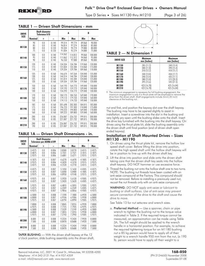
Prior to installing the drive, it is a good idea to check the drivenshaft for proper dimensions. Using Table 1 or 1A, find thedriven shaft size for the application. Verify that dimensions Aand B are within the allowable range. When dimensions areverified, proceed with the installation. The minimum andmaximum driven shaft engagements, dimension N in Figure 1,are shown in Table 2. The minimum engagement is necessaryfor full bushing engagement and the maximum (and specified)engagement is provided for use when the thrust plate kit is usedfor added retention capacity and an auxiliary removal aid(bushing nut normally used for both).
Rexnord Industries, LLC, 3001 W. Canal St., Milwaukee, WI 53208-4200168-050
(Page 2 of 26) Sizes M1130 thru M1210 • Type D Series
Shims
LevelingReferenceSurfaces
JACKINGSCREW HOLES
JACKINGSCREW HOLES
DRAINPLUG
LIFTING HOLES2 PER CORNER(16 TOTAL)
DIPSTICK/VENTHOLES
Continuous Plate
KEEP CLOSE
KEEP CLOSE
BUSHING NUT
DRIVEN SHAFT
BEARINGSUPPORT
THRUSTPLATEBORE
INPUTSHAFT
SHEAVE
NFIGURE 1
TAPER BUSHING — With the driven shaft keyway at the 12o’clock position, slide bushing assembly onto the driven shaft,
nut end first, and position the keyway slot over the shaft keyway.The bushing may have to be opened slightly to assist ininstallation. Insert a screwdriver into the slot in the bushing andvery lightly pry open until the bushing slides onto the shaft. Insertthe drive key furnished with the bushing into the shaft keyway. Ondrives using the thrust plate kit, slide the bushing assembly ontothe driven shaft until final position (end of driven shaft openended keyway).
Installation of Shaft Mounted Drives – SizesM1130 - M11901. On drives using the thrust plate kit, remove the hollow low
speed shaft cover. Before lifting the drive into position,rotate the high speed shaft until the hollow shaft keyway willbe in position to line-up with the driven shaft key.
2. Lift the drive into position and slide onto the driven shafttaking care that the driven shaft key seats into the hollowshaft keyway. DO NOT hammer or use excessive force.
3. Thread the bushing nut onto the hollow shaft one to two turns.NOTE: The bushing nut threads have been coated with ananti-seize compound at the Factory. This compound shouldnot be removed. Before re-installing a previously used nut,recoat the nut threads only with an anti-seize compound.
WARNING: DO NOT apply anti-seize or lubricant tobushing or shaft surfaces. Use of anti-seize may preventsecure connection of the drive to the shaft and cause thedrive to move.
See Table 13 for nut setscrew and wrench sizes.
a. Preferred Method — Use a spanner, chain or pipewrench to tighten the bushing nut to the torque valueindicated in Table 3. If the required torque cannot bemeasured, an approximation can be made using Table3A. The full weight should be applied to the wrenchhandle in a horizontal position. For example, to achievethe required tightening torque for an M1180 bushingnut a 85 kg person would have to apply all of theirweight to a wrench handle 950 mm from the nut, (a 190lb. person would have to apply all their weight to a
Rexnord Industries, LLC, 3001 W. Canal St., Milwaukee, WI 53208-4200 168-050
Telephone : 414-342-3131 Fax: 414-937-4359 (PN 2124650) November 2008
† The minimum engagement is necessary for full bushing engagement; themaximum engagement is only if a thrust plate will be employed to remove thedrive from the driven shaft. Shaft engagements include 5mm(.20 inch)clearance at the bushing nut.
wrench handle 3 feet from the nut). Apply Loctite 243 orequivalent to threads of the setscrew. Tighten thesetscrew to 10 Nm (90 lb-in). For drives subjected tovibratory conditions refer to Step c.
b. Optional TA Bushing Nut Tightening — When therequired tightening torque of the TA Bushing nut can not bemeasured at the low speed shaft, the torque-multiplyingcharacteristic of the drive can be utilized. Rotating the highspeed shaft of the drive while holding the TA Bushing nutstationary will allow a large torque to be reached. Fix theTA Bushing nut by securing a spanner, chain or pipewrench to the nut. Allow the wrench to contact a surfacethat will hold the force when tightening.
WARNING: Make sure the wrench will not slip andcause damage or injury.
Determine the proper rotation of the high speed shaft toachieve tightening of the stationary nut. If the drive isequipped with a backstop, verify that the backstop willallow the necessary rotation, or remove the backstop.Find the torque to apply to the high speed shaft bydividing the tightening torque indicated in Table 3 by thedrive’s ratio (Torque ÷ Ratio). Apply the calculatedtorque to the high speed shaft or coupling using aspanner, chain or pipe wrench. Be careful not todamage the usable length of the high speed shaft.Remove the fixed wrench from the TA Bushing nut andreassemble the backstop if necessary.
WARNING: Never use the prime mover to produce therequired torque. This could result in severe personalinjury or damage.
Apply Loctite 243 or equivalent to threads of setscrew.Tighten the setscrew to 10 Nm (90 lb-in) on the bushingnut. For drives subjected to vibratory conditions refer toStep c.
c. Drives Subjected to Vibratory Conditions — Extraprecautions should be taken for drives subjected tovibratory conditions. With the nut of the TA Bushingtightened to the specified torque, locate the setscrewhole in the nut of the bushing assembly. Using a 6 mm(15/64 inch) diameter drill, create a dimple in theoutside diameter of the bushing flange by drillingthrough the setscrew hole in the nut. Apply Loctite 243or equivalent to threads of setscrew and tighten intobushing nut.
d. Drives Using Thrust Plate Kit — Install thrust plate andthrust plate retaining ring in hollow shaft. Coat four tofive engaging threads of retention fastener with Loctite222 or equivalent (low strength) thread lockingcompound and thread into driven shaft end until snugtight. Reinstall shaft cover.
Removal of Shaft Mounted Drives – SizesM1130 - M1190WARNING: Lock out power source and remove all externalloads from drive before servicing drive or accessories.
1. Drain the lubricant from the drive.
2. Remove safety guards and belts (if so equipped). Removehollow shaft cover if thrust plate kit is used.
3. Removal of motor and motor mount (if so equipped).
4. Remove backstop (if so equipped).
WARNING: Drive must be supported during removal process.Use a sling and take up the slack before proceeding.
5. Remove the setscrew(s) on the bushing nut which is locatedat the output end of the hollow shaft. On drives using thethrust plate kit, remove the driven shaft retention fastener.
6. Use a spanner, pipe or chain wrench to loosen the bushingnut. Initially the nut will freely rotate counterclockwiseapproximately 180° as the nut moves from the lockedposition to the removal position. At this point anticipateresistance which indicates unseating of the bushing.Continue to rotate the nut until it is free from the hollowshaft. If unable to release the drive from the driven shaftwith the bushing nut, the thrust plate kit using a backingbolt (threaded into the driven shaft tapped hole) andremoval bolt (threaded into the thrust plate tapped hole)may be used to release the drive from the driven shaft, referto Appendix G for backing and removal bolt sizes (usersupplied). To use, remove thrust plate retaining ring andthrust plate, install backing bolt, and reinstall thrust platewith retaining ring. Remove bushing nut retaining ring.Install removal bolt in thrust plate and tighten againstbacking bolt to release drive from driven shaft (insertscrewdriver in thrust plate key slot to engage hollow shaftkeyway to prevent thrust plate rotation while tighteningremoval bolt).
7. Prepare drive for lifting by disconnecting the torque arm.
8. Slide the drive from the bushing. The bushing can be left inplace or removed as required. If bushing will not slide offthe shaft, insert a small prybar into the split of the bushingand pry the split open slightly to loosen the bushing andremove from the shaft.
Rexnord Industries, LLC, 3001 W. Canal St., Milwaukee, WI 53208-4200168-050
‡ If a torque wrench is not available, the torque can be approximated byapplying the given weight at the given distance from the nut.
Taper Bushing - Sizes M1200 & M1210Driven shafts are retained on M1200 & M1210 drives with athrust plate and three cap screw arrangement. With the drivenshaft keyway at the 12 o’clock position, slide bushing onto thedriven shaft, flange end first, and position the keyway slot overthe shaft keyway. The bushing may have to be opened slightlyto assist in installation. Insert a screwdriver into the slot in thebushing and very lightly pry open until the bushing slides ontothe shaft. Insert the drive key furnished with the bushing into theshaft keyway.
Installation of Shaft Mounted Drives - SizesM1200 M12101. Before lifting the drive into position, rotate the high speed
shaft until the hollow shaft keyway will be in position toline-up with the driven shaft key.
2. Lift the drive into position and slide onto the drive shafttaking care that the driven shaft key seats into the hollowshaft keyway. DO NOT hammer or use excessive force.
3. Align three holes in hollow shaft thrust plate with tappedholes in end of driven shaft. Insert fasteners through thrustplate and engage tapped holes in driven shaft one to twoturns by hand to ensure that fasteners are notcross-threaded.
4. Tighten fasteners to the torque vales (� 10%) listed below:M24 x 3 ..........640 Nm (470 lb-ft) for metric basedbushing bores.1.250-7UNC ...1400 Nm (1060 lb-ft) for inch basedbushing bores.
2. Remove three thrust plate fasteners, retaining ring andthrust plate from the hollow shaft.
3. Select the backing bolts from the table above and installthem into the three threaded holes in the end of the drivenshaft. The head of the backing bolts provides a workingsurface for the removal bolts.
4. Re-insert the thrust plate and retaining ring into the hollowshaft and select the removal bolts from the table above.
5. Thread three removal bolts into the thrust plate until theycontact the backing bolt heads.
6. Tighten the removal bolts equally in stages to the torqueindicated in the table above. After torquing the bolts, asinstructed, strike the bolts sharpy with a hammer andre-torque the bolts if separation of the drive from the drivenshaft did not occur. Repeat this procedure, re-torquing thebolts after each blow, until separation occurs.
7. Prepare drive for lifting by disconnecting the torque arm.
8. Slide the drive from the bushing. The bushing can be left inplace or removed as required. If bushing will not slide offthe shaft, insert a small prybar into the split of the bushingand pry the split open slightly to loosen the bushing andremove from the shaft.
Shaft ConnectionsWARNING: Provide suitable guards in accordance with localand national standards.
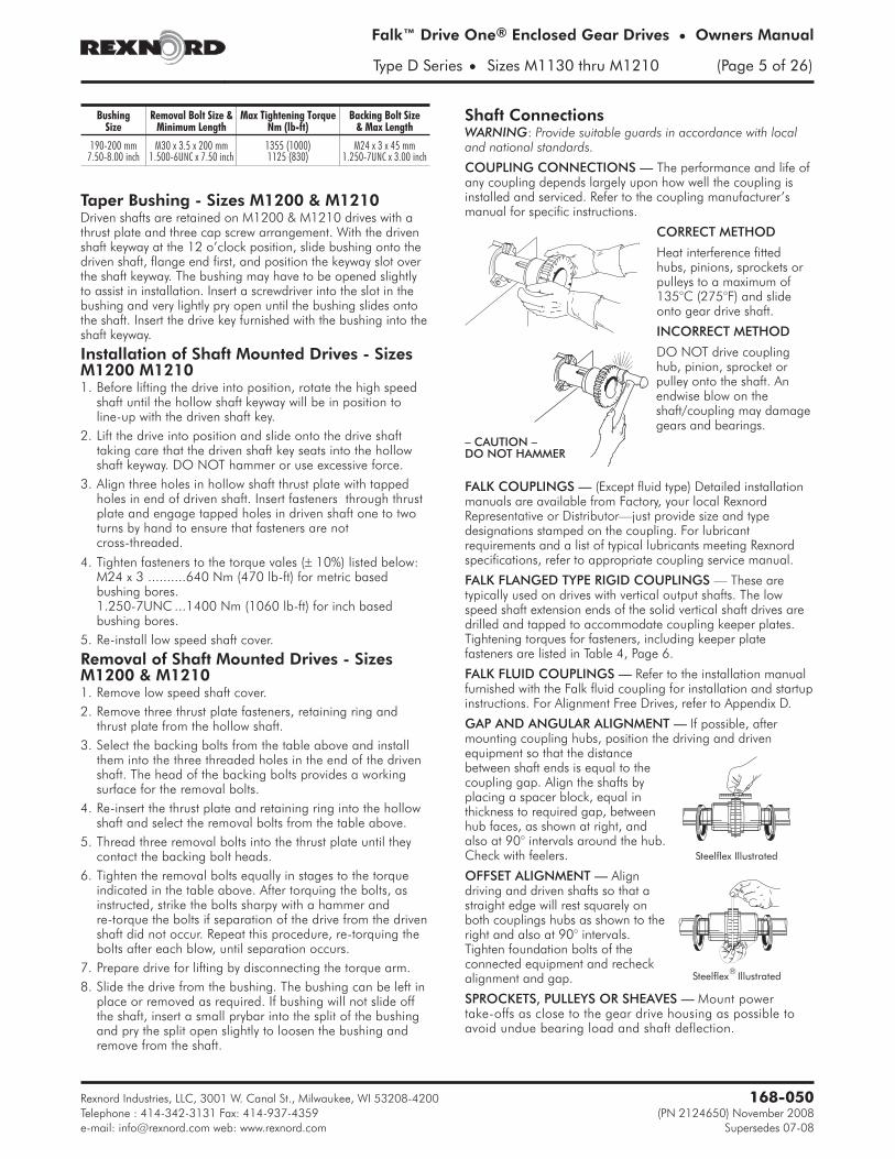
COUPLING CONNECTIONS — The performance and life ofany coupling depends largely upon how well the coupling isinstalled and serviced. Refer to the coupling manufacturer’smanual for specific instructions.
CORRECT METHOD
Heat interference fittedhubs, pinions, sprockets orpulleys to a maximum of135°C (275°F) and slideonto gear drive shaft.
INCORRECT METHOD
DO NOT drive couplinghub, pinion, sprocket orpulley onto the shaft. Anendwise blow on theshaft/coupling may damagegears and bearings.
FALK COUPLINGS — (Except fluid type) Detailed installationmanuals are available from Factory, your local RexnordRepresentative or Distributor—just provide size and typedesignations stamped on the coupling. For lubricantrequirements and a list of typical lubricants meeting Rexnordspecifications, refer to appropriate coupling service manual.
FALK FLANGED TYPE RIGID COUPLINGS — These aretypically used on drives with vertical output shafts. The lowspeed shaft extension ends of the solid vertical shaft drives aredrilled and tapped to accommodate coupling keeper plates.Tightening torques for fasteners, including keeper platefasteners are listed in Table 4, Page 6.
FALK FLUID COUPLINGS — Refer to the installation manualfurnished with the Falk fluid coupling for installation and startupinstructions. For Alignment Free Drives, refer to Appendix D.
GAP AND ANGULAR ALIGNMENT — If possible, aftermounting coupling hubs, position the driving and drivenequipment so that the distancebetween shaft ends is equal to thecoupling gap. Align the shafts byplacing a spacer block, equal inthickness to required gap, betweenhub faces, as shown at right, andalso at 90° intervals around the hub.Check with feelers.
OFFSET ALIGNMENT — Aligndriving and driven shafts so that astraight edge will rest squarely onboth couplings hubs as shown to theright and also at 90° intervals.Tighten foundation bolts of theconnected equipment and recheckalignment and gap.
SPROCKETS, PULLEYS OR SHEAVES — Mount powertake-offs as close to the gear drive housing as possible toavoid undue bearing load and shaft deflection.
Rexnord Industries, LLC, 3001 W. Canal St., Milwaukee, WI 53208-4200 168-050
Telephone : 414-342-3131 Fax: 414-937-4359 (PN 2124650) November 2008
Type D Series • Sizes M1130 thru M1210 (Page 5 of 26)
Steelflex Illustrated
Steelflex Illustrated
– CAUTION –DO NOT HAMMER
BushingSize
Removal Bolt Size &Minimum Length
Max Tightening TorqueNm (lb-ft)
Backing Bolt Size& Max Length
190-200 mm M30 x 3.5 x 200 mm 1355 (1000) M24 x 3 x 45 mm7.50-8.00 inch 1.500-6UNC x 7.50 inch 1125 (830) 1.250-7UNC x 3.00 inch
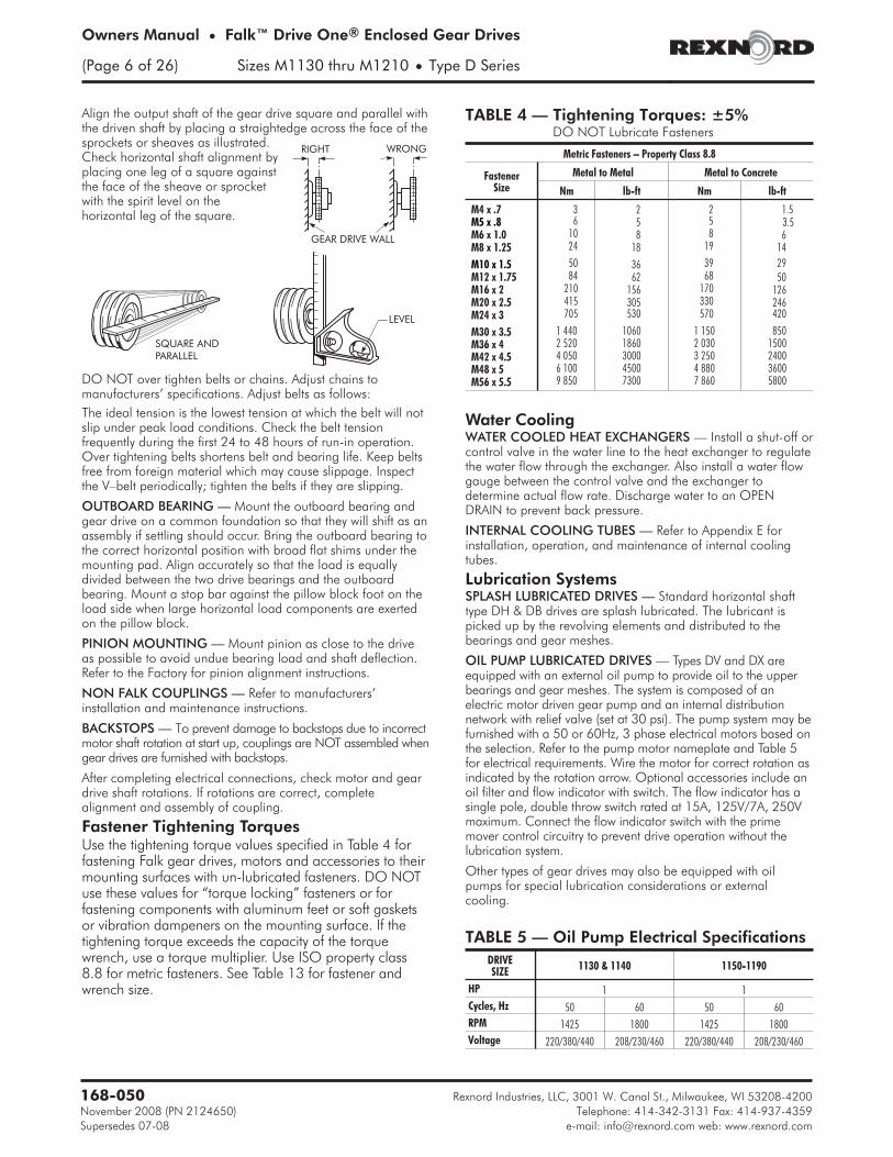
Align the output shaft of the gear drive square and parallel withthe driven shaft by placing a straightedge across the face of thesprockets or sheaves as illustrated.Check horizontal shaft alignment byplacing one leg of a square againstthe face of the sheave or sprocketwith the spirit level on thehorizontal leg of the square.
DO NOT over tighten belts or chains. Adjust chains tomanufacturers’ specifications. Adjust belts as follows:
The ideal tension is the lowest tension at which the belt will notslip under peak load conditions. Check the belt tensionfrequently during the first 24 to 48 hours of run-in operation.Over tightening belts shortens belt and bearing life. Keep beltsfree from foreign material which may cause slippage. Inspectthe V–belt periodically; tighten the belts if they are slipping.
OUTBOARD BEARING — Mount the outboard bearing andgear drive on a common foundation so that they will shift as anassembly if settling should occur. Bring the outboard bearing tothe correct horizontal position with broad flat shims under themounting pad. Align accurately so that the load is equallydivided between the two drive bearings and the outboardbearing. Mount a stop bar against the pillow block foot on theload side when large horizontal load components are exertedon the pillow block.
PINION MOUNTING — Mount pinion as close to the driveas possible to avoid undue bearing load and shaft deflection.Refer to the Factory for pinion alignment instructions.
NON FALK COUPLINGS — Refer to manufacturers’installation and maintenance instructions.
BACKSTOPS — To prevent damage to backstops due to incorrectmotor shaft rotation at start up, couplings are NOT assembled whengear drives are furnished with backstops.
After completing electrical connections, check motor and geardrive shaft rotations. If rotations are correct, completealignment and assembly of coupling.
Fastener Tightening TorquesUse the tightening torque values specified in Table 4 forfastening Falk gear drives, motors and accessories to theirmounting surfaces with un-lubricated fasteners. DO NOTuse these values for “torque locking” fasteners or forfastening components with aluminum feet or soft gasketsor vibration dampeners on the mounting surface. If thetightening torque exceeds the capacity of the torquewrench, use a torque multiplier. Use ISO property class8.8 for metric fasteners. See Table 13 for fastener andwrench size.
Water CoolingWATER COOLED HEAT EXCHANGERS — Install a shut-off orcontrol valve in the water line to the heat exchanger to regulatethe water flow through the exchanger. Also install a water flowgauge between the control valve and the exchanger todetermine actual flow rate. Discharge water to an OPENDRAIN to prevent back pressure.
INTERNAL COOLING TUBES — Refer to Appendix E forinstallation, operation, and maintenance of internal coolingtubes.
Lubrication SystemsSPLASH LUBRICATED DRIVES — Standard horizontal shafttype DH & DB drives are splash lubricated. The lubricant ispicked up by the revolving elements and distributed to thebearings and gear meshes.
OIL PUMP LUBRICATED DRIVES — Types DV and DX areequipped with an external oil pump to provide oil to the upperbearings and gear meshes. The system is composed of anelectric motor driven gear pump and an internal distributionnetwork with relief valve (set at 30 psi). The pump system may befurnished with a 50 or 60Hz, 3 phase electrical motors based onthe selection. Refer to the pump motor nameplate and Table 5for electrical requirements. Wire the motor for correct rotation asindicated by the rotation arrow. Optional accessories include anoil filter and flow indicator with switch. The flow indicator has asingle pole, double throw switch rated at 15A, 125V/7A, 250Vmaximum. Connect the flow indicator switch with the primemover control circuitry to prevent drive operation without thelubrication system.
Other types of gear drives may also be equipped with oilpumps for special lubrication considerations or externalcooling.
Rexnord Industries, LLC, 3001 W. Canal St., Milwaukee, WI 53208-4200168-050
(Page 6 of 26) Sizes M1130 thru M1210 • Type D Series
TABLE 5 — Oil Pump Electrical Specifications
DRIVESIZE
1130 & 1140 1150-1190
HP 1 1
Cycles, Hz 50 60 50 60
RPM 1425 1800 1425 1800
Voltage 220/380/440 208/230/460 220/380/440 208/230/460
TABLE 4 — Tightening Torques: ±5%DO NOT Lubricate Fasteners
Metric Fasteners – Property Class 8.8
FastenerSize
Metal to Metal Metal to Concrete
Nm lb-ft Nm lb-ft
M4 x .7 3 2 2 1.5M5 x .8 6 5 5 3.5M6 x 1.0 10 8 8 6M8 x 1.25 24 18 19 14
M10 x 1.5 50 36 39 29M12 x 1.75 84 62 68 50M16 x 2 210 156 170 126M20 x 2.5 415 305 330 246M24 x 3 705 530 570 420
M30 x 3.5 1 440 1060 1 150 850M36 x 4 2 520 1860 2 030 1500M42 x 4.5 4 050 3000 3 250 2400M48 x 5 6 100 4500 4 880 3600M56 x 5.5 9 850 7300 7 860 5800
RIGHT WRONG
GEAR DRIVE WALL
LEVEL
SQUARE ANDPARALLEL
Lubrication RecommendationsCarefully follow lubrication instructions on the gear drivenameplate, warning tags, and installation manuals furnishedwith the gear drive.
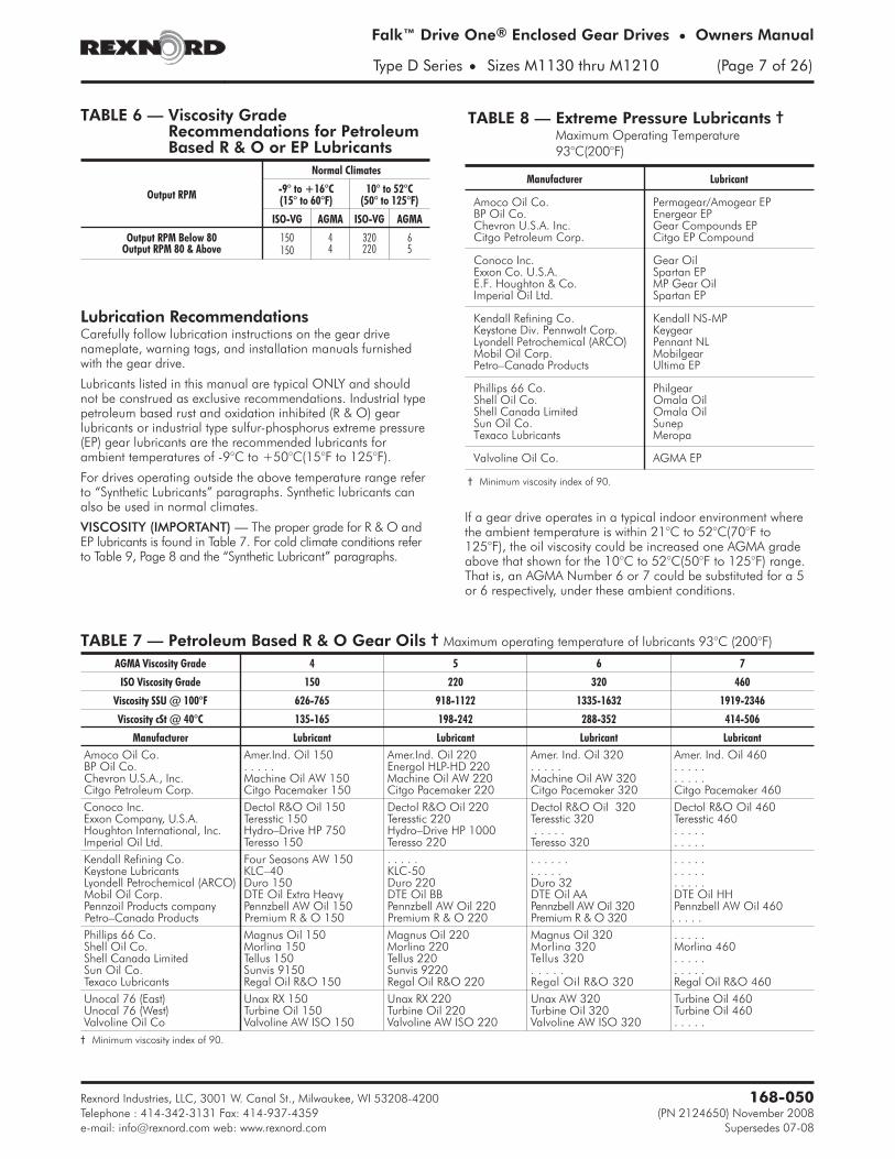
Lubricants listed in this manual are typical ONLY and shouldnot be construed as exclusive recommendations. Industrial typepetroleum based rust and oxidation inhibited (R & O) gearlubricants or industrial type sulfur-phosphorus extreme pressure(EP) gear lubricants are the recommended lubricants forambient temperatures of -9°C to +50°C(15°F to 125°F).
For drives operating outside the above temperature range referto “Synthetic Lubricants” paragraphs. Synthetic lubricants canalso be used in normal climates.
VISCOSITY (IMPORTANT) — The proper grade for R & O andEP lubricants is found in Table 7. For cold climate conditions referto Table 9, Page 8 and the “Synthetic Lubricant” paragraphs.
If a gear drive operates in a typical indoor environment wherethe ambient temperature is within 21°C to 52°C(70°F to125°F), the oil viscosity could be increased one AGMA gradeabove that shown for the 10°C to 52°C(50°F to 125°F) range.That is, an AGMA Number 6 or 7 could be substituted for a 5or 6 respectively, under these ambient conditions.
Rexnord Industries, LLC, 3001 W. Canal St., Milwaukee, WI 53208-4200 168-050
Telephone : 414-342-3131 Fax: 414-937-4359 (PN 2124650) November 2008
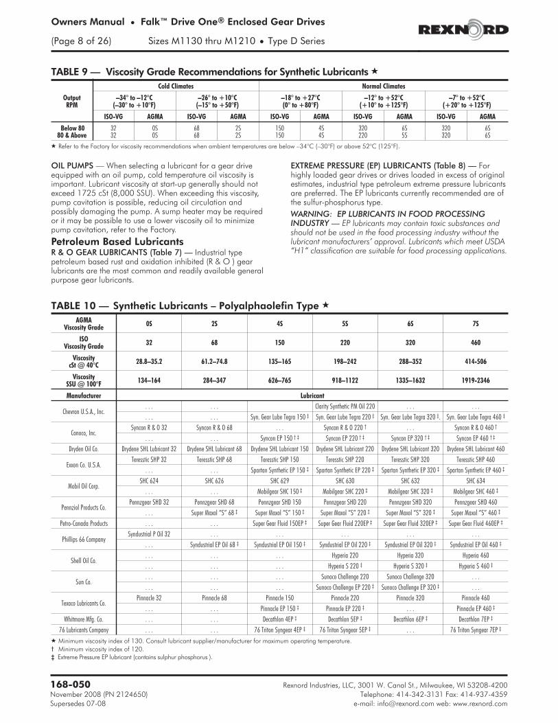
OIL PUMPS — When selecting a lubricant for a gear driveequipped with an oil pump, cold temperature oil viscosity isimportant. Lubricant viscosity at start-up generally should notexceed 1725 cSt (8,000 SSU). When exceeding this viscosity,pump cavitation is possible, reducing oil circulation andpossibly damaging the pump. A sump heater may be requiredor it may be possible to use a lower viscosity oil to minimizepump cavitation, refer to the Factory.
Petroleum Based LubricantsR & O GEAR LUBRICANTS (Table 7) — Industrial typepetroleum based rust and oxidation inhibited (R & O ) gearlubricants are the most common and readily available generalpurpose gear lubricants.
EXTREME PRESSURE (EP) LUBRICANTS (Table 8) — Forhighly loaded gear drives or drives loaded in excess of originalestimates, industrial type petroleum extreme pressure lubricantsare preferred. The EP lubricants currently recommended are ofthe sulfur-phosphorus type.
WARNING: EP LUBRICANTS IN FOOD PROCESSINGINDUSTRY — EP lubricants may contain toxic substances andshould not be used in the food processing industry without thelubricant manufacturers’ approval. Lubricants which meet USDA“H1” classification are suitable for food processing applications.
Rexnord Industries, LLC, 3001 W. Canal St., Milwaukee, WI 53208-4200168-050
� Refer to the Factory for viscosity recommendations when ambient temperatures are below –34°C (–30°F) or above 52°C (125°F).
CAUTION: LUBRICANTS & INTERNAL BACKSTOPS — Donot use lubricants with anti-wear additives or lubricantformulations including PTFE (Teflon), lead derivatives, graphiteor molybdenum disulfide in drives equipped with backstops.Some lubricants in Table 8 may contain several of theseadditives.
Synthetic LubricantsSynthetic lubricants of the polyalphaolefin type arerecommended for cold climate operation, high temperatureapplications, extended temperature range (all season)operation, and/or extended lubricant change intervals. Theproper viscosity grade of synthetic lubricant is given in Table 9.Refer to Table 10 for Synthetic lubricants.
WARNING: SYNTHETIC LUBRICANTS IN FOODPROCESSING INDUSTRY — Synthetic lubricants may containtoxic substances and should not be used in the foodprocessing industry without the lubricant manufacturers’approval. Lubricants which meet USDA “H1” classification aresuitable for food processing applications.
Bearing and Seal GreasesAll drives and some backstops have grease lubricated seals.Some vertical shaft and specially mounted drives have greaselubricated bearings. Drives are shipped with NLGI #2 grease inthe seal housing cavities unless otherwise specified. Refer toTable 11 for grease recommendations.
GREASE LUBRICATED BEARINGS — Vertical shaft driveswith drywells have grease lubricated lower low speedbearings. These bearings are lubricated at the Factorywith an NLGI#2 grease. Refer to the preventivemaintenance instructions for greasing instructions.
GREASE LUBRICATED SEALS — Drive One drives arefurnished with grease purged seals which minimize the entry ofcontaminants into the drive. Drives are shipped with NLGI #2grease in the seal housing cavities unless otherwise specified. Ifgrease could contaminate the product, as in the food and drug
industries, it should be removed. A grease that meets USDA“H1” classification is suitable for food processing applications.
Oil LevelsTYPES DH & DB — Fill the drive with oil to the level indicatedon the oil dipstick. Approximate oil capacities are given on thedrive nameplate.
The inspection cover is sealed with a non hardening chemicalgasket eliminator. When replacing the inspection cover, run abead of Loctite 515 Gasket Eliminator � (or equivalent) aroundthe perimeter of the inspection opening, making sure to circlethe fastener holes.� Product of Henkel Corp., Rocky Hill, CT.
DRIVES WITH OIL PUMPS — Types DV, DX, and occasionallyother types of gear drives will be equipped with oil pumps forcooling or special lubrication considerations. If a drive isequipped with an oil pump, fill the drive to the level marked onthe dipstick. Run the lubrication system for several minutes to fillthe system components. Verify that the pump is circulating oilproperly, then recheck oil level. If necessary, add oil tocompensate for filter and/or cooler.
Before starting the gear drive, rotate the input shaft to check forobstructions. Then start the drive and allow it to run withoutload for several minutes. Shut down and recheck oil level. Ifeverything is satisfactory, the drive is ready for operation.
Preventive MaintenanceAFTER FIRST WEEK — Check alignment of total system andrealign where necessary. Also tighten all external bolts andplugs where necessary. DO NOT readjust the internal gear orbearing settings in the drive, these were permanently set at theFactory. See Table 13 for fastener and wrench sizes.
AFTER FIRST MONTH — Proceed as follows:
1. Operate drive until old sump oil reaches normal operatingtemperature. Shut down drive and drain immediately.
2. Immediately flush drive with an oil of the same type andviscosity grade as the original charge (warmed toapproximately 38°C (100°F) in cold weather) by rapidlypouring or pumping a charge equal to 25 - 100% of theinitial fill volume or until clean oil flows through the drain.
3. Close the drain and refill the drive to the correct level withnew oil of the correct type and viscosity.
PERIODICALLY —
1. Check the oil level of the drive when it is stopped and atambient temperature. Add oil if needed. If the oil level isABOVE the high oil level mark on the dipstick, have the oilanalyzed for water content. Moisture in the oil may indicatethat a seal or the heat exchanger is leaking. If so, replacethe defective part immediately and change the oil. DONOT fill above the mark indicated as leakage or undueheating may result.
2. Check coupling alignment to make certain that foundationsettling has not caused excessive misalignment.
3. If drive is equipped with a fan, periodically clean accumulatedforeign matter from the fan, guard, and deflector.
4. If drive is equipped with a torque arm, check for freemovement.
Rexnord Industries, LLC, 3001 W. Canal St., Milwaukee, WI 53208-4200 168-050
Telephone : 414-342-3131 Fax: 414-937-4359 (PN 2124650) November 2008
Lubricant ChangesOIL ANALYSIS REPORT— Checking oil condition at regularintervals is recommended. In the absence of more specificlimits, the guidelines listed below may be used to indicate whento change oil:
1. Water content is greater than 500 ppm (0.05%).
2. Iron content exceeds 150 ppm.
3. Silicon (dust/dirt) exceeds 25 ppm.
4. Viscosity changes more than 15%.
PETROLEUM LUBRICANTS — For normal operating conditions,change gear oils every 6 months or 2500 operating hours,whichever occurs first. Change oil more frequently when gear drivesoperate in extremely humid, chemical or dust laden atmospheres. Inthese cases, R & O and EP lubricants should be changed every 3 to4 months or 1500 to 2000 hours. If the drive is operated in an areawhere the temperatures vary with seasons, change oil viscosity gradeto suit temperature. Lubricant suppliers can test oil periodically andrecommend economical change intervals.
SYNTHETIC LUBRICANTS — Synthetic lube change intervals canbe extended to 8000 - 10,000 hours depending upon operatingtemperatures and lubricant contamination. Change oil morefrequently when gear drives operate in extremely humid, chemicalor dust laden atmospheres. In these cases, synthetic lubricantsshould be changed every 4 to 6 months or 4000 to 6000 hours.Laboratory analysis is recommended for optimum lubricant lifeand gear drive performance. Change lube with change inambient temperature, if required. Refer to Table 9 for syntheticlubricant viscosity recommendations.
Grease Lubricated Seals — Depending on the frequency anddegree of contamination (at least every six months or whenchanging oil in the drive), purge contaminated grease fromseals by slowly pumping fresh grease, WITH A HAND GREASE
GUN, through the seal cavity until fresh grease flows out alongthe shaft. Wipe off purged grease. Refer to Table 11 for NLGI#2 greases. Some of these greases are of the IP type and maycontain toxic substances not allowed in the food processingindustry. A grease that meets the USDA “H1” classification issuitable for food processing applications.
CAUTION: Rapid greasing with a power grease gun can forcegrease inward past the seals causing seal leaks.
GREASE LUBRICATED BEARINGS (TYPES DV AND DX) —Most vertical low speed shaft drives have a grease lubricatedlower low speed bearing. Grease bearings during oil changesor at intervals of every 6 months or 2500 hours of operationwhichever is less.
VERTICAL SHAFT DRIVES — Remove the pressure relief plugbefore greasing. Pump grease into bearing cage until freshgrease appears at the plug. Replace the pressure relief plugwhen finished. See figure below.
Refer to Table 11 for NLGI #2 greases. Some of these greasesare of the EP type and may contain toxic substances notallowed in the food processing industry. A grease that meets theUSDA “H1” classification is suitable for food processingapplications.
Rexnord Industries, LLC, 3001 W. Canal St., Milwaukee, WI 53208-4200168-050
Stored & Inactive Gear DrivesEach gear drive is protected with a rust preventative that willprotect parts against rust for a period of 4 months in anoutdoor shelter or 12 months in a dry building after shipmentfrom the Factory.
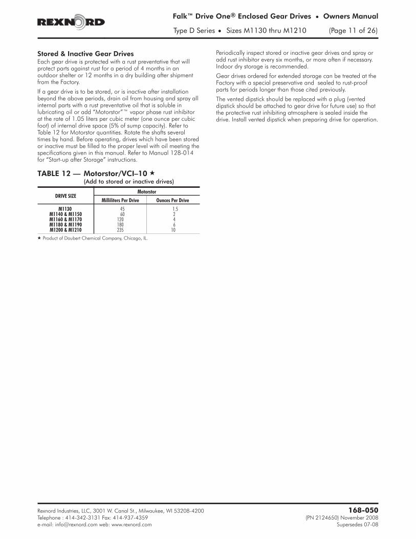
If a gear drive is to be stored, or is inactive after installationbeyond the above periods, drain oil from housing and spray allinternal parts with a rust preventative oil that is soluble inlubricating oil or add “Motorstor”™ vapor phase rust inhibitorat the rate of 1.05 liters per cubic meter (one ounce per cubicfoot) of internal drive space (5% of sump capacity). Refer toTable 12 for Motorstor quantities. Rotate the shafts severaltimes by hand. Before operating, drives which have been storedor inactive must be filled to the proper level with oil meeting thespecifications given in this manual. Refer to Manual 128-014for “Start-up after Storage” instructions.
Periodically inspect stored or inactive gear drives and spray oradd rust inhibitor every six months, or more often if necessary.Indoor dry storage is recommended.
Gear drives ordered for extended storage can be treated at theFactory with a special preservative and sealed to rust-proofparts for periods longer than those cited previously.
The vented dipstick should be replaced with a plug (venteddipstick should be attached to gear drive for future use) so thatthe protective rust inhibiting atmosphere is sealed inside thedrive. Install vented dipstick when preparing drive for operation.
Rexnord Industries, LLC, 3001 W. Canal St., Milwaukee, WI 53208-4200 168-050
Telephone : 414-342-3131 Fax: 414-937-4359 (PN 2124650) November 2008
� Product of Daubert Chemical Company, Chicago, IL.
Adjustable Torque Arm InstallationIntroductionThe Drive One adjustable tie rod style torque arm is availablefor all shaft mounted Drive One sizes, parallel shaft Type DHonly. It is used to support the drive when mounted in a standardhorizontal position, refer to the Factory for other positions. Thetorque arm is mounted directly to the drive with an anchorbracket. The torque arm requires mounting holes in the drivenequipment support structure to provide for clevis bracketattachment. The customer is responsible for determining thestructural integrity of their support member.
MountingIt is natural for the drive system to move during operation. Thismovement is due to run out from the driven equipment shaftand gear drive low speed shaft. Clearance in the torque armassembly will accommodate the motion of the drive. To allowfor the movement, the torque arm should be centered at itsattachment point on the drive system and also centered in theclevis bracket on the support member. Over-tightening orfailure to center the torque arm in the mounting will restrict thedrive’s motion and will result in premature failure of the drive ordriven equipment. The torque arm should be perpendicular tothe support structure ± 2° when looking at the end of the drive,see Figure 1.
Installation1. Position the drive on the driven equipment shaft such that
the torque arm is perpendicular and centered in the clevismounted to the supporting structure and at its attachmentpoint on the drive system. Ideally, the clevis bracket shouldbe added to the structure after the drive has been securedto the driven equipment.NOTE: Do not fasten the torque to the support structure atthis time.
2. Secure the drive to the driven equipment via the TA Bushingor rigid coupling connection.
3. Check that the torque arm remains perpendicular andcentered in the clevis if mounted. If the torque arm is notperpendicular and centered, reposition the drive on thedriven equipment shaft. If the clevis bracket is not mounted,position and mount at this time.
4. The exact position of the torque arm may vary within therange shown in Figure 2. For torque arm mountings otherthan shown, refer to the Factory. If it is necessary to shortenthe torque arm assembly, cut the excess from either tie rodend on Sizes M1130 through M1190 only.
5. The support to which the clevis bracket is mounted mustsustain the load from the torque reaction shown in Table 1.The maximum load reaction through the torque arm occurswhen the torque arm is located in the extreme off angleposition. Use Class 8.8 fasteners to anchor the clevisbracket. Refer to Table 2 for fastener size and tighteningtorque.
6. Bolt the torque arm to both the clevis bracket and the driveanchor bracket and tighten the bolts until seated againstthe brackets. DO NOT bend the bracket as clearancebetween the clevis brackets and tie rod is necessary.
Rexnord Industries, LLC, 3001 W. Canal St., Milwaukee, WI 53208-4200168-050
‡ Load includes moment due to motor and motor mount with torque arm atmaximum angle.
TABLE 2 — Tie Rod Clevis Bracket fastenerTightening Torque
DRIVESIZE
FastenerSize †
Tightening Torque - Nm (lb-ft)
Steel Foundation Concrete Foundation
M1130-M1140 M20 x 2.5 415 (305) 330 (246)M1150-M1160 M24 x 3.0 705 (530) 570 (420)M1170-M1210 M30 X 3.5 1440 (1060) 1150 (850)
† Class 8.8 fasteners required.
Rod End Adjustable Torque Arm InstallationIntroductionThe Drive One rod end type adjustable torque arm isavailable for all shaft mounted Drive One sizes, bothparallel shaft Type DH and right angle Type DB. It isused to support the drive when mounted in a standardhorizontal position; other positions may be available(consult Factory). The torque arm accessory is suitablefor use on swing bases, bedplates, or mounted directly tothe drive. Three styles of rod end torque arms areavailable: (1) Standard style for swingbase or bedplatemounting, (2) Clevis style for mounting directly to thedrive foot, (3) Turnbuckle style for greater length andadjustment. The torque arm requires mounting holes inthe driven equipment support structure to provide forattachment. The customer is responsible for determiningthe structural integrity of their support member.
MountingIt is natural for the drive system to move duringoperation. This movement is due to runout from thedriven equipment shaft, gear drive low speed shaft andthe connection of the two. Rod ends containing plainspherical bearings form a link to provide a resilientmounting support that accommodates the motion of thedrive. To allow for maximum movement, the torque armmust be perpendicular to the supports and rod endscentered in the mounting anchor bracket. Restricting thedrive’s motion in any way may result in premature failureof the drive or driven equipment.
Installaton1. Position the drive on the driven equipment shaft such
that the torque arm link is centered in the anchorbracket. Ideally, the anchor bracket mounting holesshould be added to the structure after the drive hasbeen secured to the driven equipment.
NOTE: Do not fasten the torque arm to the supportstructure at this time.
2. Secure the drive to the driven equipment via the TABushing, shrink disc or rigid coupling connection.
3. Mount the anchor bracket or clevis to the drive ordrive system if not already done. Locate the positionof the anchor bracket to be mounted to the supportstructure. Match drill the mounting holes for M20 Cl.8.8 or 0.75 inch Grade 5 fasteners or better. Lockwashers and flat washers are also required.
NOTE: Torque arm must be vertical (� 1°) in bothdirections after installation.
4. (IF REQUIRED) Assemble rod end components tocreate a link. A combination of male/female rodends, clevis/male rod end or turnbuckle/male rodends are required dependent on torque arm style. Allstyles require jam nuts to lock linkage. Refer toFigures 1 thru 3.
NOTE: Rod ends must be assembled such that the relativeposition of one rod end head to the other is parallel.Loosen locknut and adjust if necessary. See Figure 4.
5. For Standard and Turnbuckle style torque arm, installpin through one lug of anchor bracket mounted todrive. Position spacer, then rod end and finallysecond spacer on pin. Finish positioning pin withinanchor bracket. Install retaining ring to secure thepin. See Figure 1 or 3. For Clevis style torque arm,install crowned pin through clevis and drive foot.Secure pin with retaining ring. See Figure 2.
6. Install pin in anchor bracket mounted to supportingstructure with spacers in a similar manner. The drivemay need to be rotated about the low speed shaft toinstall second pin. If the drive has a backstop, it maybe necessary to disconnect the backstop to rotate thedrive. Refer to the backstop instructions for removal.
7. If the drive system is not horizontal, the rod endlinkage can be adjusted (within the limits indicated inthe catalog or certified print) to level the drive.
8. Verify the torque arm link is centered in the anchorbracket and is not restricting motion of the drive.
9. Some rod ends may be provided with grease fittingsfor lubricating. Grease rod end at every scheduledmaintenance or at least every six months. See Table11 for approved greases.
Rexnord Industries, LLC, 3001 W. Canal St., Milwaukee, WI 53208-4200 168-050
Telephone : 414-342-3131 Fax: 414-937-4359 (PN 2124650) November 2008
Appendix B • Falk™ Drive One® Enclosed Gear Drives
(Page 14 of 26) Sizes M1130 thru M1210 • Type D Series
TORQUEARM PIN
TORQUEARM PIN
ROD END(MALE)
ROD END(FEMALE)
JAM NUT
RETAININGRING
RETAININGRING
ANCHORBRACKET
ANCHORBRACKET
SPACER
SPACER
MOUNTING HARDWARE(SUPPLIED BY CUSTOMER)
MOUNTING HARDWARE(PROVIDED)
FIGURE 1
CROWNEDTORQUEARM PIN
CLEVIS
ROD END
ANCHORBRACKET
RETAININGRINGJAM NUT
TORQUEARM PIN
RETAININGRING
SPACER
MOUNTING HARDWARE(SUPPLIED BY CUSTOMER)
FIGURE 2
TURNBUCKLE
TORQUEARM PIN
TORQUEARM PIN
JAM NUT
JAM NUT
ANCHORBRACKET
ANCHORBRACKET
SPACER
RETAININGRING
RETAININGRING
SPACER
ROD END
ROD END
MOUNTING HARDWARE(SUPPLIED BY CUSTOMER)
MOUNTING HARDWARE(PROVIDED)
FIGURE 3
ROD ENDHEAD
ROD ENDHEAD
JAM NUT
INCORRECTLINK ASSEMBLY -ROD END HEADS
NOT PARALLEL
CORRECTLINK ASSEMBLY -ROD END HEADS
PARALLEL
FIGURE 4
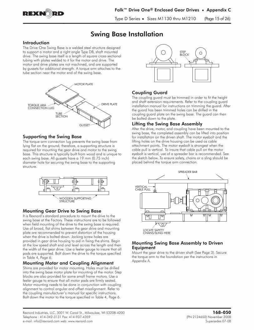
Swing Base InstallationIntroductionThe Drive One Swing Base is a welded steel structure designedto support a motor and a right angle Type DB, shaft mounteddrive. The swing base itself is a length of square cross-sectionaltubing with plates welded to it for the motor and drive. Themotor and drive plates are not machined, and are supportedby gussets for additional strength. A torque arm attaches to thetube section near the motor end of the swing base.
Supporting the Swing BaseThe torque arm connection lug prevents the swing base fromlying flat on the ground; therefore, a supporting structure isrequired for mounting the gear drive and motor to the swingbase. This structure is typically built from wood and is unique toeach swing base. All gussets have a 19 mm (0.75 inch)diameter hole for securing the swing base to the supportingstructure.
Mounting Gear Drive to Swing BaseIt is Rexnord’s standard procedure to mount the drive to theswing base at the Factory. These instructions are to be followedwhen field mounting of the drive to the swing base is required.Use of broad, flat shims between the gear drive and mountingplate are recommended to prevent distortion of the housingwhen the drive is bolted down. Jacking screw holes areprovided in gear drive housing to aid in fixing the shims. Beginat the low speed shaft end and level across the length and thenthe width of the gear drive. Use a feeler gauge to insure that allpads are supported. Bolt down the drive to the torque specifiedin Table 4, Page 6.
Mounting Motor and Coupling AlignmentShims are provided for motor mounting. Holes must be drilledinto the swing base motor plate for mounting of the motor. Stepblocks are also provided for some small frame motors. Use afeeler gauge to ensure that all motor pads are firmly seated.Motor mounting needs to be done in conjunction with couplingalignment to control angular and offset misalignment. Refer tothe coupling manufacturer’s manual for specific instructions.Bolt down the motor to the torque specified in Table 4, Page 6.
Coupling GuardThe coupling guard must be trimmed in order to fit the heightand shaft extension requirements. Refer to the coupling guardinstallation manual for instructions on trimming the guard. Afterthe guard has been trimmed holes can be drilled in thecoupling guard plate on the swing base. The guard can thenbe bolted down to the plate.
Lifting the Swing Base AssemblyAfter the drive, motor, and coupling have been mounted to theswing base, the completed assembly can be lifted into positionfor installation on the driven shaft. The motor eyebolt and thelifting holes on the drive housing can be used as cableattachment points. The motor eyebolt is strongest when thecable pull is vertical. To insure that cable pull on the motoreyebolt is vertical, use of a spreader bar is recommended. Seethe sketch below. To ensure safety, chains or a sling should beplaced behind the torque arm connection.
Mounting Swing Base Assembly to DrivenEquipmentMount the gear drive to the driven shaft (See Page 3). Securethe torque arm to the foundation per the instructions inAppendix A.
Rexnord Industries, LLC, 3001 W. Canal St., Milwaukee, WI 53208-4200 168-050
Telephone : 414-342-3131 Fax: 414-937-4359 (PN 2124650) November 2008
Falk™ Drive One® Enclosed Gear Drives • Appendix C
Type D Series • Sizes M1130 thru M1210 (Page 15 of 26)
DRIVE PLATE
MOTOR PLATE
TORQUE ARMCONNECTION LUG
TUBESECTION
GUSSET
WOODEN SUPPORTINGSTRUCTURE
STEPBLOCK
SPREADER BAR
VERTICALCABLE PULL
LOCATE SAFETYCHAINS/SLING HERE
Alignment Free Assembly and Installation - Welded DesignIntroductionThe Alignment Free Drive design consists of a shaft mounteddrive, bell housing, motor adapter plate, torque arm, motorand coupling. When assembled, the bell housing, motoradapter, and motor locate off registers, resulting in alignmentof the motor and gear drive shafts. Therefore, no additionalalignment is required for the high-speed coupling.
Assembly InstructionsThe bell housing is fastened to the drive’s high speed end usingcap screws through the four mounting holes on that face, (seeTable 1 for size and torque). The bell housing will locate on thebevel head of the drive. Read instructions provided with highspeed coupling prior to assembly.
Fluid CouplingLocation of the fluid coupling on the high speed shaft of thedrive is determined by the provided shaft spacer. Install the fluidcoupling on the high-speed shaft of the gear drive per fluidcoupling instructions. If a shaft fan is required, remove everyother of the twelve delay fill chamber fasteners. Install the fanadapter ring to the fluid coupling using the long socket headcap screws provided. Place a mounting post between the delayfill chamber flange and the adapter ring as shown in Figure 1.After all fasteners and mounting posts are installed, tighten capscrews to the torque specified in Table 2. Install the six fansegments to the outer bolt circle of the adapter ring, see Table2 for tightening torque.
Once the fluid coupling is installed, the motor adapter platecan be mounted to the bell housing, also being located by aregister. Measurements must be taken to accurately position themotor half of the coupling hub on the motor shaft. First,
measure the distance from the motor mounting face to the endof the motor shaft, (A). Then measure the distance from themotor adapter plate face to the hub on the fluid coupling, (B).Finally measure the distance from the hub flange to the hubend, (C). The desired gap can be found in Table 3, based oncoupling size.
Calculate the hub protrusion:
Protrusion = (A + Gap) – (B + C)
If the calculated protrusion is a negative value, the huboverhangs the shaft by that amount. (Figure 2)
Once the hub is correctly located on the motor shaft, the motorcan be mounted to the motor adapter plate. The hubs will bealigned and come together to the proper gap. To fill the fluidcoupling to the proper oil level, align the mark on theperimeter of the fluid coupling with the mark in the center ofthe inspection window on the bell housing on the side oppositethe TA Bushing nut or shaft extension. To locate the correctmark on the fluid coupling, begin by aligning the fill hole of thefluid coupling with the mark in the inspection window. For fillangles less than 90°, rotate the fill plug upward until the marks
Rexnord Industries, LLC, 3001 W. Canal St., Milwaukee, WI 53208-4200168-050
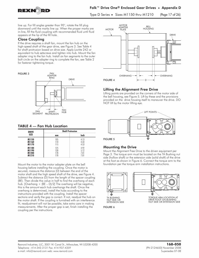
line up. For fill angles greater than 90°, rotate the fill plugdownward until the marks line up. When the proper marks arein-line, fill the fluid coupling with recommended fluid until fluidappears at the lip of the fill hole.
Close CouplingIf the drive requires a shaft fan, mount the fan hub on thehigh-speed shaft of the gear drive, see Figure 3. See Table 4for shaft protrusion based on drive size. Apply Loctite 242 orequivalent to hub setscrews and tighten into hub. Mount the fanadapter ring to the fan hub. Install six fan segments to the outerbolt circle on the adapter ring to complete the fan, see Table 2for fastener tightening torque.
Mount the motor to the motor adapter plate on the bellhousing before installing the coupling. Once the motor issecured, measure the distance (D) between the end of themotor shaft and the high speed shaft of the drive, see Figure 4.Subtract the distance (D) from the length of the spacer coupling(BE). Then divide this value in half to find the overhang of eachhub. [Overhang + (BE – D)/2] The overhang will be negative,this is the amount each hub overhangs the shaft. Once theoverhang is determined, install the hubs according to theinstructions provided with the coupling. Install the spacersections and verify the gap is correct. If not, readjust the hub onthe motor shaft. If the coupling is furnished with an interferencefit, readjustment will not be possible, take extra care in makingmeasurements. After the proper gap is set, finish installing thecoupling per the instructions.
Lifting the Alignment Free DriveLifting points are provided on the corners of the motor side ofthe bell housing, see Figure 5. Lift by these and the provisionsprovided on the drive housing itself to maneuver the drive. DONOT lift by the motor lifting eye.
Mounting the DriveMount the Alignment Free Drive to the driven equipment perPage 3. The torque arm must be located on the TA Bushing nutside (hollow shaft) or the extension side (solid shaft) of the driveat the foot as shown in Figure 6. Connect the torque arm to thefoundation per the torque arm installation instructions.
Rexnord Industries, LLC, 3001 W. Canal St., Milwaukee, WI 53208-4200 168-050
Telephone : 414-342-3131 Fax: 414-937-4359 (PN 2124650) November 2008
Alignment Free Assembly and Installation - Cast DesignIntroductionThe Alignment Free Drive design consists of a shaft mountedgear drive, bell housing, torque arm, motor and coupling.When assembled, the gear drive, bell housing and motorlocate off registers, resulting in alignment of the shafts.Therefore, no additional alignment is required for thehigh-speed coupling.
Assembly InstructionsThe Bell Housing is fastened to the gear drive’s high-speed endusing capscrews through the four mounting holes on that facewith a nut and lock washer, (see Table 1 for size and torque).Apply Loctite® #242 or equivalent to mounting fastenerthreads. The bell housing will locate on the bevel head of thegear drive. Read instructions provided with high speed coupling
prior to assembly.
High Speed Shaft FanHigh speed shaft fan is standard on all Drive One AlignmentFree Drives. Fan size and position is dependent on bell housingcasting and high speed coupling, not drive size. Assemble fanto fan hub, apply Loctite #242 or equivalent to fastenerthreads and tighten.
CAUTION: Do not over-tighten fasteners into plastic fan as fanmay crack.
Mount the fan hub on the gear drive high speed shaft such thatthe set screw hole in the hub is towards the end of the shaft.Locate the hub axially at the values listed in Table 2.
Dimensions listed are from the inside face of the bell housing tothe far side of the hub, see Figure 1. Apply Loctite #242 orequivalent to threads of the set screw and tighten over key tosecure hub in position. Fan hub must be installed prior toinstalling high speed coupling hub.
Assemble fan shroud mounting rails to bell housing. Assemblefan cowling with expanded metal guard to back of fanshroud/plates on same fasteners. Mount fan shroud assemblyto mounting rails. The cowling may require to be notched toallow clearance for the bell housing to drive mountingfasteners. Rotate fan to ensure clearance, reposition fan hub ifnecessary. Split fan guard may be removed or installed withoutdisrupting high speed coupling. See Figure 2.
Fluid Coupling:The fluid coupling can be installed/removed without removingthe motor, (see fluid coupling instructions for procedure).Mount the coupling hubs to the drive high speed shaft and themotor shaft. Hubs are to be mounted flush with the end of theshafts (coupling hubs may be furnished with an interference fit).Mount the motor to the bell housing, apply Loctite #242 orequivalent fastener threads and tighten to proper torque. Installfluid coupling per coupling instructions.
To fill the fluid coupling to the proper oil level, install the smalltop cover on the bell housing. Rotate the fluid coupling suchthat the fill hole is up and fill with the approximate quantity ofoil (see coupling instructions for oil type and quantity). Rotatethe coupling in either direction to align the mark on theperimeter of the fluid coupling with the mark in the center ofthe cover on the bell housing. A container should be placed tocatch any excess oil that may spill from the fill hole. If oil drainsfrom the fill hole, allow all excess to drain to achieve the properfill level. If no oil drains when marks are aligned, rotatecoupling back and add more oil. Repeat process until excessoil drains and proper fill level is achieved.
Rexnord Industries, LLC, 3001 W. Canal St., Milwaukee, WI 53208-4200168-050
Close Coupling D011723 130 5.12Close Coupling D011725 115 4.53
� Casting number located on inside sidewall of bell housing.
FIGURE 1
FIGURE 2
Close Coupling:Mount the coupling hubs to the drive high speed shaft andmotor shaft. Hubs are to be mounted flush with the end of theshafts unless otherwise noted (coupling hubs may be furnishedwith an interference fit). Mount the motor to the bell housing,apply Loctite #242 or equivalent to fastener threads andtighten to proper torque. Install high speed coupling percoupling instructions.
Guards and Covers:Install bell housing covers, (top and bottom). Install airdeflectors on the top, bottom and both sides of the gear drive.The bends of the deflectors are perforated to allow positioningof the deflectors. Air deflectors should be positionedapproximately 25mm [1 inch] from the nearest housing surfaceby bending deflector towards or away from the drive.
Torque Arm:The carriage, adjusting rod, brackets and support bar arefurnished pre-assembled from the Factory. Assemble the rodends with heads perpendicular to each other (90°) as shown inFigure 3. Rod end threads must be engaged a minimum of onetimes thread diameter. Attach female rod end to carriage withpin. Place a spacer on each side of the rod end. Secure pinwith locking plate. Carriage may be adjusted from center toeither far end of the housing to facilitate installation of pin.
Ensure that adjusting rod locking plate is NOT installed at thistime as it will prevent adjustment of the torque arm assembly.Assemble anchor bracket to male rod end with a spacer oneach side and secure with pin and retaining ring.
Lifting the Alignment Free DriveLifting points are provided on the corners of the motor end ofthe bell housing, see Figure 4. Lift by these and the provisionsprovided on the drive housing itself to maneuver the drive. DO
NOT lift by the motor lifting eye.
Mounting the Drive:Mount the Alignment Free Drive to the driven equipment perpages 2 and 3 of this manual. With Alignment Free driveassembly supported, rotate adjusting screw to move torque armto desired position and to line up with foundation. Torque Armmust be perpendicular in both directions (± 1°), adjust screw ifnot. Install locking plate to lock the adjusting screw, (plate canbe installed on either side). Remove support from drive andsecure anchor bracket to foundation. Use M24 Class 8.8 [1inch Grade 5] or better fasteners with lock and flat washers tomount anchor bracket. Slots are provided such that torque armcan be mounted perpendicular.
CAUTION: Do NOT adjust torque arm screw after support isremoved and torque arm is under any load.
Rexnord Industries, LLC, 3001 W. Canal St., Milwaukee, WI 53208-4200 168-050
Telephone : 414-342-3131 Fax: 414-937-4359 (PN 2124650) November 2008
Falk™ Drive One® Enclosed Gear Drives • Appendix D
Type D Series • Sizes M1140 thru M1210 (Page 19 of 26)
LIFT POINTS
A
A PIN LOCKINGPLATE
BRACKET
SUPPORT BAR
RETAININGRING
ANCHORBRACKET
SPACER
MOUNTINGHARDWARE(SUPPLIED BYCUSTOMER)
PIN
JAM NUTMALEROD END
LOCKINGPLATE
SECTION A-A
ADJUSTINGSCREW
BRACKET
CARRIAGE
THREADEDADJUSTING ROD
FEMALEROD ENDSPACER
CARRIAGEPIN
FIGURE 3
FIGURE 4
Electric Fan Installation & MaintenanceInstallationThe installation and troubleshooting of electric cooling fans areto be carried out by a qualified electrician according to theapplicable local, state, province and federal codes. Inspect forany damage that may have occurred during transit. Check allbolts, screws, set screws, etc. Retighten as required. Beforeinstalling, rotate the blade to be sure it does not rub. Adjust ifnecessary. Before installation, read the entire manual carefully.
This guide is pertinent only to electric fans furnished by theFactory and manufactured by Multifan Inc. (can be verifiedfrom nameplate on the electric fan). In the event the electric fanfurnished by the Factory is of a special nature (manufactured byan alternate fan manufacturer), please contact the Factory forappropriate electric fan installation and maintenanceinstructions.
General Safety InformationWarning: To reduce the risk of fire, electric shock, or personalinjury, observe the following:
1. Use this electric fan only in the manner intended by themanufacture. If you have any questions, contact Factory.
2. Before servicing or cleaning the fan, switch the power off atthe service panel and lock out to prevent the power frombeing switched on accidentally.
3. Follow all local electrical and safety codes, as well as theNational Electrical Code (NEC) and Occupational Safetyand Health Act (OSHA).
4. Fan motor must be securely and adequately grounded.
5. All working parts should be grounded.
6. When cleaning electrical equipment always use anapproved cleaning agent. See CLEANING in NOTESsection, Page 18.
7. For general ventilation and cooling use only. DO NOT useif hazardous or explosive materials and vapors are present.
Guidelines For InstallationBefore connecting the electric fan, check if the information onthe fan motor name plate is in accordance with the actual mainsupply voltage, phase and frequency.
Warning: To reduce the risk of fire, electric shock, or personalinjury, observe the following:
1. Switch off the main power supply and lock out beforeinstalling, servicing or making connections to the fan.
2. Installation work and electrical wiring must be done by aqualified person(s) in accordance with all applicable codesand standards, including fire-rated construction.
3. The fan should be securely mounted. Recheck the mountinghardware and tighten as necessary.
4. The fan motor must always be grounded. The installation ofa motor protection switch is recommended. See Figure 1for wiring diagrams.
5. Mount the motor guard if removed. The motor guard mustbe installed at all times during operation to prevent injuryto personnel by rotating fan blade.
6. Use liquid tight electrical fittings and conduit.
Rexnord Industries, LLC, 3001 W. Canal St., Milwaukee, WI 53208-4200168-050
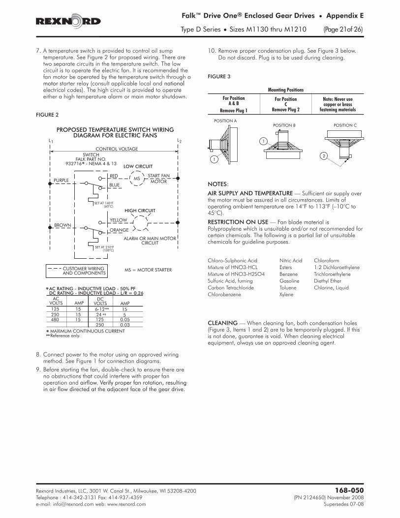
7. A temperature switch is provided to control oil sumptemperature. See Figure 2 for proposed wiring. There aretwo separate circuits in the temperature switch. The lowcircuit is to operate the electric fan. It is recommended thefan motor be operated by the temperature switch through amotor starter relay (consult applicable local and nationalelectrical codes). The high circuit is provided to operateeither a high temperature alarm or main motor shutdown.
8. Connect power to the motor using an approved wiringmethod. See Figure 1 for connection diagrams.
9. Before starting the fan, double-check to ensure there areno obstructions that could interfere with proper fanoperation and airflow. Verify proper fan rotation, resultingin air flow directed at the adjacent face of the gear drive.
10. Remove proper condensation plug. See Figure 3 below.Do not discard. Plug is to be used during cleaning.
NOTES:
AIR SUPPLY AND TEMPERATURE — Sufficient air supply overthe motor must be assured in all circumstances. Limits ofoperating ambient temperature are 14°F to 113°F (–10°C to45°C).
RESTRICTION ON USE — Fan blade material isPolypropylene which is unsuitable and/or not recommended forcertain chemicals. The following is a partial list of unsuitablechemicals for guideline purposes.
CLEANING — When cleaning fan, both condensation holes(Figure 3, Items 1 and 2) are to be temporarily plugged. If thisis not done, guarantee is void. When cleaning electricalequipment, always use an approved cleaning agent.
Rexnord Industries, LLC, 3001 W. Canal St., Milwaukee, WI 53208-4200 168-050
Telephone : 414-342-3131 Fax: 414-937-4359 (PN 2124650) November 2008
Cooling Tube DescriptionThe internal cooling tube accessory is a network of finnedcooling tubes, Factory installed in the base of a drive housing,for heat removal. The cooling tubes operate submerged in the oilof the drive sump. The revolving elements provide the necessaryoil flow around the cooling tubes for efficient heat transfer. No oilpumps are required. The external requirement for the coolingtube system is a clean water hookup supplying a flow rate of 2gallons (8 liters) per minute at a maximum temperature of 90°F(32°C). An inlet water temperature of 70°F (21°C) is required toobtain the system catalog thermal power rating with a sump oiltemperature of 200°F (93°C).
The number of cooling tubes required varies with drive size,type and number of reductions. Cooling tubes are connected inseries to maintain the optimum water flow velocity in the tubeswith the specified water flow rate of 2 to 5 gallons (8 to 19liters) per minute. Note: A typical Falk PC cooling assemblyrequires between 2 to 70 gallons (8 to 265 liters) of water perminute, depending upon PC size and cooling requirements.
All cooling tube system connections are made outside of thehousing to eliminate the possibility of water leakage into the drivesump. Seal rings are used at all connections for ease of disassemblyand reassembly. The standard cooling tubes are 90/10 coppernickel alloy with aluminum fins. Cooling tube connections arecadmium plated mild steel with “Buna-N” seal rings.
Water connections are .500"-14 NPT fittings located at the highspeed end. The water outlet is located on the high speed endof the drive. The water inlet connection is a straight fittinglocated on the lowest cooling tube in the drive.
The water outlet connection is a right angle fitting (faced up)located on the uppermost tube in the drive. The cooling tubesystem connections are selected and located so that the coolingsystem is always full of water during operation for maximumheat transfer. The water inlet and outlet connections may bemoved to the opposite end of the drive by removing the waterinlet, outlet and all “loop end” fitting assemblies and byreinstalling them on the same tubes at the opposite end of thedrive. Refer to the Maintenance Instructions on Page 22 andFigures 7 & 8 on Page 23 for disassembly and reassembly.
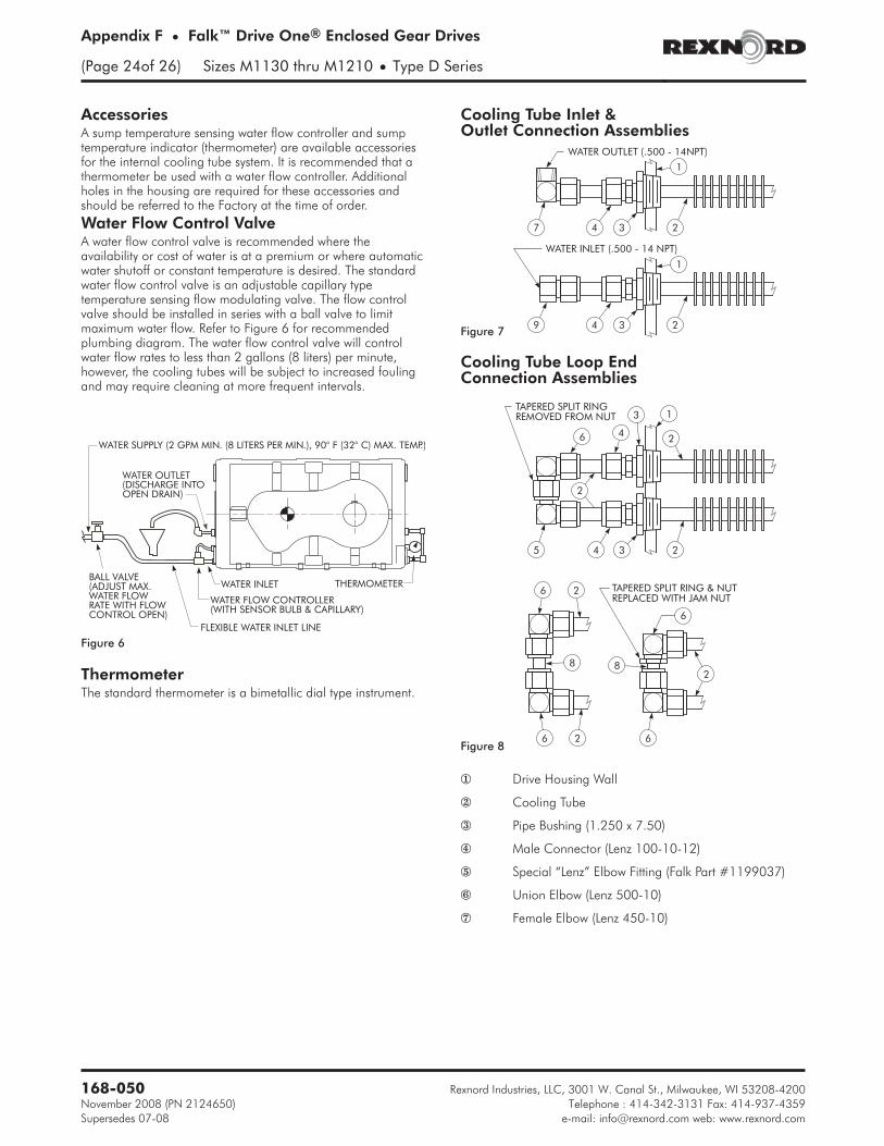
Installation & Operation1. Connect the .500"-14 NPT straight water inlet fitting to a
source of clean fresh water. Water must be regulated to aminimum of 2 gallons (8 liters) per minute and must notexceed 90°F (32°C).
2. Connect the .500"-14 NPT right angle water outlet fitting(faced up) to an open drain. Do not pressurize the coolingtube system. The turned up water outlet fitting ensures thatthe system is always full of water during operation.
3. Control water flow rate to between 2 and 5 gallons (8 and19 liters) per minute to minimize fouling at low flow rates ortube erosion at high flow rates. The water flow rate may bereduced to 1 gallon (4 liters) per minute if clean fresh(drinking quality) water is used and the sump oiltemperature can be maintained within the maximum limit of200°F (93°C).
4. For shutdowns at ambient temperatures less than 32°F(0°C), drain the cooling tube system by removing the “loopend” assemblies on the end of the drive opposite the waterinlet. Refer to Figure 8 on Page 23 for typical assembliesand record location of assemblies for reinstallationpurposes.
Rexnord Industries, LLC, 3001 W. Canal St., Milwaukee, WI 53208-4200168-050
Appendix F • Falk™ Drive One® Enclosed Gear Drives
(Page 22of 26) Sizes M1130 thru M1210 • Type D Series
Assembly of Seal Ring FittingsNote: For Disassembly of seal ring fittings, reverse the steps ofthe following assembly procedure.1. Figure 1 — Deburr tube end to prevent cutting the rubber
seal ring during assembly.
2. Figure 2 — Slide nut and tapered split ring on tube. Thelarge end of the tapered split ring must face the fitting body.
3. Figure 3 — Lubricate the rubber seal ring. Insert the tubeinto the fitting body past the rubber seal ring.
4. Figure 4 — Slide the tapered split ring against the fitting body.Lubricate O.D. of tapered split ring with #2 bearing grease.
5. Figure 5 — Assemble nut to fitting and tighten hand tight.Turn nut with a wrench one turn or until the tapered splitring is flush with the end of the nut.
Maintenance InstructionsThe cooling tube system is designed to be removed from thedrive housing without disturbing the drive or its foundation,provided sufficient room is available at either end of thehousing for tube withdrawal. All tube connections are outsidethe drive and are of the seal ring type for ease of maintenanceand reusability.
Light coatings of sludge or scale will cause a reduction in heattransfer capacity of the system. Therefore, periodic cleaning ofthe system may be required to restore the heat transfer capacity.
The cooling tube system may be cleaned by flushing withcommercially available cleaning compounds such as “Oakite”or “Dowell.” The commercially available cleaning compoundsare corrosive and must be used in accordance with theirmanufacturer’s recommendations. Cleaning may also beaccomplished by means of a rod or wire brush. Remove thetube end seal ring fittings (Figures 7 & 8 on Page 23) and passa .500" (12 mm) diameter rod or wire brush through the tubesto remove the scale. Tube I.D. is .527" (13.39 mm). Aftercleaning all tubes, reinstall the tube end seal ring fittings.
The outside of the cooling tubes (aluminum fins) may be cleanedby removing the tubes from the housing and cleaning with steamor a suitable solvent. To remove the tubes from the housing,remove all seal ring fittings from the tubes. Remove the 1.250-11NPT x .750-14 NPT pipe bushings from one end of the drive. Aspecial deep well, thin wall socket (1.812 hex by 7" deep) may berequired to remove and reinstall the pipe bushings.
CAUTION: Take care not to damage cooling tube ends duringdisassembly, cleaning and reassembly.
Withdraw the tubes from the housing through the 1.250-11NPT holes using a .375" (10 mm) diameter rod through thetube as a disassembly and reassembly aid. After cleaning,reinstall the tubes in the drive. Coat pipe bushing threads withthread sealant and reinstall the pipe bushings and tube fittingsin the reverse order of disassembly. Install the loop endassemblies in the same positions as before disassembly.
Refer to Column 1 for seal ring fitting assembly procedures.Seal ring fittings use standard No. 114 (.625 I.D. x .812 O.D. x.094 W) Buna-N seal rings if replacements are required.
Rexnord Industries, LLC, 3001 W. Canal St., Milwaukee, WI 53208-4200 168-050
Telephone : 414-342-3131 Fax: 414-937-4359 (PN 2124650) November 2008
Falk™ Drive One® Enclosed Gear Drives • Appendix F
Type D Series • Sizes M1130 thru M1210 (Page 23of 26)
TUBE
DEBURRED END
BODYTAPEREDSPLIT RING
NUT
RUBBER SEAL RING
TEFLON BACK-UP RING
BODYTAPERED SPLIT RING
TIGHTEN NUTUNTIL FLUSH
Figure 1
Figure 2
Figure 3
Figure 4
Figure 5
AccessoriesA sump temperature sensing water flow controller and sumptemperature indicator (thermometer) are available accessoriesfor the internal cooling tube system. It is recommended that athermometer be used with a water flow controller. Additionalholes in the housing are required for these accessories andshould be referred to the Factory at the time of order.
Water Flow Control ValveA water flow control valve is recommended where theavailability or cost of water is at a premium or where automaticwater shutoff or constant temperature is desired. The standardwater flow control valve is an adjustable capillary typetemperature sensing flow modulating valve. The flow controlvalve should be installed in series with a ball valve to limitmaximum water flow. Refer to Figure 6 for recommendedplumbing diagram. The water flow control valve will controlwater flow rates to less than 2 gallons (8 liters) per minute,however, the cooling tubes will be subject to increased foulingand may require cleaning at more frequent intervals.
ThermometerThe standard thermometer is a bimetallic dial type instrument.
Rexnord Industries, LLC, 3001 W. Canal St., Milwaukee, WI 53208-4200168-050
Appendix F • Falk™ Drive One® Enclosed Gear Drives
(Page 24of 26) Sizes M1130 thru M1210 • Type D Series
� Drive Housing Wall
� Cooling Tube
� Pipe Bushing (1.250 x 7.50)
� Male Connector (Lenz 100-10-12)
� Special “Lenz” Elbow Fitting (Falk Part #1199037)
Union Elbow (Lenz 500-10)
Female Elbow (Lenz 450-10)
WATER OUTLET(DISCHARGE INTOOPEN DRAIN)
BALL VALVE(ADJUST MAX.WATER FLOWRATE WITH FLOWCONTROL OPEN)
WATER INLET THERMOMETER
WATER FLOW CONTROLLER(WITH SENSOR BULB & CAPILLARY)
FLEXIBLE WATER INLET LINE
WATER SUPPLY (2 GPM MIN. (8 LITERS PER MIN.), 90° F (32° C) MAX. TEMP.)
Figure 6
WATER INLET (.500 - 14 NPT)
1
9 4 3 2
WATER OUTLET (.500 - 14NPT)
1
7 4 3 2
TAPERED SPLIT RINGREMOVED FROM NUT 1
2
5
6 4
3
2
34 2
Cooling Tube Inlet &Outlet Connection Assemblies
Cooling Tube Loop EndConnection Assemblies
6 2
6
TAPERED SPLIT RING & NUTREPLACED WITH JAM NUT
82
8
6 62
Figure 7
Figure 8
Thrust Plate & Fastener UsageThrust plate usage is optional. To use, remove hollow shaftcover from gear drive, Slide bushing with shaft key onto drivenshaft near final position (Shaft Length “N” - 5mm or 0.20 in.)and slide gear drive onto driven shaft. Tighten bushing nut tospecified torque. Verify location of drive on driven shaft to bewithin angular limits of the drive torque arm. Install thrust plateand thrust plate retaining ring. Coat four or five engagingthreads of the retention fastener with a low strength threadlocking compound and install snug tight. Install hollow shaftcover.
Rexnord Industries, LLC, 3001 W. Canal St., Milwaukee, WI 53208-4200 168-050
Telephone : 414-342-3131 Fax: 414-937-4359 (PN 2124650) November 2008
M1130 M20 x 2.5 x 75 .750-10UNC x 3.00 M20 x 2.5 x 40 .750-10 x 1.50 M24 x 3 x 70 M24 x 3 x 70 341 13.43 284 11.18M1140 M24 x 3 x 90 1.000-8UNC x 3.50 M24 x 3 x 45 1.00-8 x 2.00 M30 x 3.5 x 80 M30 x 3.5 x 80 386 15.20 319 12.55M1150 M24 x 3 x 90 1.000-8UNC x 3.50 M24 x 3 x 45 1.00-8 x 2.00 M30 x 3.5 x 80 M30 x 3.5 x 80 406 15.98 334 13.15
M1160 M24 x 3 x 90 1.000-8UNC x 3.50 M24 x 3 x 45 1.00-8 x 2.00 M30 x 3.5 x 80 M30 x 3.5 x 80 454 17.87 407 16.02M1170 M30 x 3.5 x 100 1.125-7UNC x 3.75 M30 x 3.5 x 60 1.125-7 x 2.25 M36 x 4 x 90 M36 x 4 x 90 436 17.17 392 15.44M1180 M30 x 3.5 x 100 1.125-7UNC x 3.75 M30 x 3.5 x 60 1.125-7 x 2.25 M36 x 4 x 90 M36 x 4 x 90 503 19.80 450 17.72M1190 M30 x 3.5 x 100 1.125-7UNC x 3.75 M30 x 3.5 x 60 1.125-7 x 2.25 M36 x 4 x 90 M36 x 4 x 90 549 21.61 502 19.76
� Retention fastener is factory supplied (Grade 8,8 metric & Grade 5 inch).† Backing and removal bolts are user supplied (Removal bolt Grade 8,8 minimum).
‡ Shaft length (N) and Keyway (L) are required when using thrust plate and supplied retention fastener.
5 mm, 20 INCHES
THREADED HOLE
RETENTION FASTENER
REMOVAL BOLT
BACKING BOLT WITH FLAT WASHER(S)
AUXILIARY RELEASE SYSTEM - USER PROVIDED WHEN REQUREDLOOSEN BUSHING NUT AND REMOVE NUT RETAINING RING BEFORE USINGADD FLAT WASHERS AT BACKING BOLT IF NEEDED
N
L
KEY
Directions for Inverting Drives DH2 & DB3
Rexnord Industries, LLC, 3001 W. Canal St., Milwaukee, WI 53208-4200168-050
Appendix H • Falk™ Drive One® Enclosed Gear Drives
(Page 26of 26) Sizes M1130 thru M1210 • Type D Series
5A - INSPECTION COVER3A - DIPSTICK IN HOLE OPPOSITE
OF LOW SPEED GEAR LOCATION
2A - HEX SOCKET PIPE PLUG1 - EACH END
1A - SQUARE HEAD MAGNETIC DRAIN PLUG1 - EACH END4A - HEX SOCKET PIPE PLUG
STANDARD MOUNT(INSPECTION COVER UP)
3B - DIPSTICK IN HOLE OPPOSITELOW SPEED GEAR LOCATION
2B - HEX SOCKET PIPE PLUG1 - EACH ENDSEALED WITH LOCTITE PIPE JOINTCOMPOUND #30557 (P/N D004945)
1B - SQUARE HEAD MAGNETIC DRAIN PLUG1 - EACH ENDSEALED WITH LOCTITE PIPE JOINTCOMPOUND #30557 (P/N D004945)
5B - INSPECTION COVERIF COVER WAS REMOVED APPLY A CONTINOUOUS BEAD OFLOCTITE 515 GASKET ELIMINATOR (P/N 99409561) OR EQUIVALENTTO HOUSING INSPECTION COVER BOLTING SURFACE. MAKESURE THAT THE BEAD IS LOCATED INSIDE THE BOLT PATTERNAND CIRCLES EACH BOLT HOLE. INSTALL INSPECTION COVERAND TIGHTEN FASTENERS TO 85 Nm (63lb-ft)
RELOCATE MAGNETIC DRAIN PLUGS (BOTH ENDS) FROM1A TO 1B AND SWITCH THE SOCKET HEAD PLUGSFROM 2A TO 2B
RELOCATE THE DIPSTICK FROM 3A TO 3B AND SWITCHTHE SOCKET HEAD PLUGS FROM 4A TO 4B.BE SURE TO LOCATE THE DIPSTICK ON THE OPPOSITESIDE FROM THE LOW SPEED GEAR TO AVOID INTERFERENCE